CN101426542A - Skin-mountable device in packaging comprising coated seal member - Google Patents
Skin-mountable device in packaging comprising coated seal memberDownload PDFInfo
- Publication number
- CN101426542A CN101426542ACNA2007800145600ACN200780014560ACN101426542ACN 101426542 ACN101426542 ACN 101426542ACN A2007800145600 ACNA2007800145600 ACN A2007800145600ACN 200780014560 ACN200780014560 ACN 200780014560ACN 101426542 ACN101426542 ACN 101426542A
- Authority
- CN
- China
- Prior art keywords
- skin
- package
- sealing member
- mounting surface
- assembly
- Prior art date
- Legal status (The legal status is an assumption and is not a legal conclusion. Google has not performed a legal analysis and makes no representation as to the accuracy of the status listed.)
- Withdrawn
Links
- 238000004806packaging method and processMethods0.000titledescription5
- 238000007789sealingMethods0.000claimsabstractdescription59
- 239000000853adhesiveSubstances0.000claimsabstractdescription23
- 230000001070adhesive effectEffects0.000claimsabstractdescription23
- 230000001954sterilising effectEffects0.000claimsabstractdescription16
- 239000000463materialSubstances0.000claimsabstractdescription12
- 210000003491skinAnatomy0.000claimsdescription22
- 210000002615epidermisAnatomy0.000claimsdescription19
- 238000003780insertionMethods0.000claimsdescription18
- 230000037431insertionEffects0.000claimsdescription18
- 239000011248coating agentSubstances0.000claimsdescription14
- 238000000576coating methodMethods0.000claimsdescription14
- 230000035515penetrationEffects0.000claimsdescription5
- 239000012790adhesive layerSubstances0.000claimsdescription2
- 230000035699permeabilityEffects0.000abstractdescription4
- 238000001802infusionMethods0.000description21
- 238000003860storageMethods0.000description18
- 239000003814drugSubstances0.000description16
- 229940079593drugDrugs0.000description15
- 239000012530fluidSubstances0.000description14
- 230000001681protective effectEffects0.000description11
- NOESYZHRGYRDHS-UHFFFAOYSA-NinsulinChemical compoundN1C(=O)C(NC(=O)C(CCC(N)=O)NC(=O)C(CCC(O)=O)NC(=O)C(C(C)C)NC(=O)C(NC(=O)CN)C(C)CC)CSSCC(C(NC(CO)C(=O)NC(CC(C)C)C(=O)NC(CC=2C=CC(O)=CC=2)C(=O)NC(CCC(N)=O)C(=O)NC(CC(C)C)C(=O)NC(CCC(O)=O)C(=O)NC(CC(N)=O)C(=O)NC(CC=2C=CC(O)=CC=2)C(=O)NC(CSSCC(NC(=O)C(C(C)C)NC(=O)C(CC(C)C)NC(=O)C(CC=2C=CC(O)=CC=2)NC(=O)C(CC(C)C)NC(=O)C(C)NC(=O)C(CCC(O)=O)NC(=O)C(C(C)C)NC(=O)C(CC(C)C)NC(=O)C(CC=2NC=NC=2)NC(=O)C(CO)NC(=O)CNC2=O)C(=O)NCC(=O)NC(CCC(O)=O)C(=O)NC(CCCNC(N)=N)C(=O)NCC(=O)NC(CC=3C=CC=CC=3)C(=O)NC(CC=3C=CC=CC=3)C(=O)NC(CC=3C=CC(O)=CC=3)C(=O)NC(C(C)O)C(=O)N3C(CCC3)C(=O)NC(CCCCN)C(=O)NC(C)C(O)=O)C(=O)NC(CC(N)=O)C(O)=O)=O)NC(=O)C(C(C)CC)NC(=O)C(CO)NC(=O)C(C(C)O)NC(=O)C1CSSCC2NC(=O)C(CC(C)C)NC(=O)C(NC(=O)C(CCC(N)=O)NC(=O)C(CC(N)=O)NC(=O)C(NC(=O)C(N)CC=1C=CC=CC=1)C(C)C)CC1=CN=CN1NOESYZHRGYRDHS-UHFFFAOYSA-N0.000description10
- 238000000034methodMethods0.000description10
- 230000007246mechanismEffects0.000description8
- 239000012528membraneSubstances0.000description7
- 238000004891communicationMethods0.000description6
- 238000010276constructionMethods0.000description6
- 230000002093peripheral effectEffects0.000description6
- 102000004877InsulinHuman genes0.000description5
- 108090001061InsulinProteins0.000description5
- 229940125396insulinDrugs0.000description5
- 239000010410layerSubstances0.000description5
- 229920002635polyurethanePolymers0.000description5
- 239000004814polyurethaneSubstances0.000description5
- 230000008569processEffects0.000description5
- 239000003522acrylic cementSubstances0.000description4
- 238000012377drug deliveryMethods0.000description4
- 238000002347injectionMethods0.000description4
- 239000007924injectionSubstances0.000description4
- 230000004913activationEffects0.000description3
- 239000008280bloodSubstances0.000description3
- 210000004369bloodAnatomy0.000description3
- 206010012601diabetes mellitusDiseases0.000description3
- 239000011888foilSubstances0.000description3
- 239000007788liquidSubstances0.000description3
- 238000007920subcutaneous administrationMethods0.000description3
- 239000000126substanceSubstances0.000description3
- WQZGKKKJIJFFOK-GASJEMHNSA-NGlucoseNatural productsOC[C@H]1OC(O)[C@H](O)[C@@H](O)[C@@H]1OWQZGKKKJIJFFOK-GASJEMHNSA-N0.000description2
- 230000009471actionEffects0.000description2
- 239000003795chemical substances by applicationSubstances0.000description2
- 230000008878couplingEffects0.000description2
- 238000010168coupling processMethods0.000description2
- 238000005859coupling reactionMethods0.000description2
- 230000000881depressing effectEffects0.000description2
- 239000008103glucoseSubstances0.000description2
- 230000010196hermaphroditismEffects0.000description2
- 238000005259measurementMethods0.000description2
- 239000000203mixtureSubstances0.000description2
- 230000000149penetrating effectEffects0.000description2
- 229920001296polysiloxanePolymers0.000description2
- 229920006264polyurethane filmPolymers0.000description2
- 108090000623proteins and genesProteins0.000description2
- 239000000243solutionSubstances0.000description2
- 230000001225therapeutic effectEffects0.000description2
- 210000001519tissueAnatomy0.000description2
- 238000003466weldingMethods0.000description2
- 241001631457CannulaSpecies0.000description1
- IAYPIBMASNFSPL-UHFFFAOYSA-NEthylene oxideChemical compoundC1CO1IAYPIBMASNFSPL-UHFFFAOYSA-N0.000description1
- 238000004497NIR spectroscopyMethods0.000description1
- 210000001015abdomenAnatomy0.000description1
- 239000013543active substanceSubstances0.000description1
- 230000000712assemblyEffects0.000description1
- 238000000429assemblyMethods0.000description1
- 230000004888barrier functionEffects0.000description1
- 230000015572biosynthetic processEffects0.000description1
- 206010061592cardiac fibrillationDiseases0.000description1
- 238000013461designMethods0.000description1
- 238000012938design processMethods0.000description1
- 229940126534drug productDrugs0.000description1
- 210000000624ear auricleAnatomy0.000description1
- 230000000694effectsEffects0.000description1
- 230000002708enhancing effectEffects0.000description1
- 210000003722extracellular fluidAnatomy0.000description1
- 230000002600fibrillogenic effectEffects0.000description1
- 230000009969flowable effectEffects0.000description1
- 238000005755formation reactionMethods0.000description1
- 238000009472formulationMethods0.000description1
- 239000000499gelSubstances0.000description1
- 230000003054hormonal effectEffects0.000description1
- 229940088597hormoneDrugs0.000description1
- 239000005556hormoneSubstances0.000description1
- 239000000416hydrocolloidSubstances0.000description1
- 239000012535impuritySubstances0.000description1
- 238000007373indentationMethods0.000description1
- 238000007689inspectionMethods0.000description1
- 238000009434installationMethods0.000description1
- 235000012054mealsNutrition0.000description1
- 235000016709nutritionNutrition0.000description1
- 230000003204osmotic effectEffects0.000description1
- 230000000737periodic effectEffects0.000description1
- 230000002085persistent effectEffects0.000description1
- 239000000825pharmaceutical preparationSubstances0.000description1
- 229920000728polyesterPolymers0.000description1
- 229920001451polypropylene glycolPolymers0.000description1
- 230000002028prematureEffects0.000description1
- 238000003825pressingMethods0.000description1
- 238000007639printingMethods0.000description1
- 102000004196processed proteins & peptidesHuman genes0.000description1
- 108090000765processed proteins & peptidesProteins0.000description1
- 102000004169proteins and genesHuman genes0.000description1
- 230000008439repair processEffects0.000description1
- 238000005096rolling processMethods0.000description1
- 239000003566sealing materialSubstances0.000description1
- 239000000758substrateSubstances0.000description1
- 239000000725suspensionSubstances0.000description1
- 239000010409thin filmSubstances0.000description1
- 239000012780transparent materialSubstances0.000description1
Images


Classifications
- A—HUMAN NECESSITIES
- A61—MEDICAL OR VETERINARY SCIENCE; HYGIENE
- A61M—DEVICES FOR INTRODUCING MEDIA INTO, OR ONTO, THE BODY; DEVICES FOR TRANSDUCING BODY MEDIA OR FOR TAKING MEDIA FROM THE BODY; DEVICES FOR PRODUCING OR ENDING SLEEP OR STUPOR
- A61M5/00—Devices for bringing media into the body in a subcutaneous, intra-vascular or intramuscular way; Accessories therefor, e.g. filling or cleaning devices, arm-rests
- A61M5/14—Infusion devices, e.g. infusing by gravity; Blood infusion; Accessories therefor
- A61M5/142—Pressure infusion, e.g. using pumps
- A61M5/14244—Pressure infusion, e.g. using pumps adapted to be carried by the patient, e.g. portable on the body
- A61M5/14248—Pressure infusion, e.g. using pumps adapted to be carried by the patient, e.g. portable on the body of the skin patch type
- A—HUMAN NECESSITIES
- A61—MEDICAL OR VETERINARY SCIENCE; HYGIENE
- A61M—DEVICES FOR INTRODUCING MEDIA INTO, OR ONTO, THE BODY; DEVICES FOR TRANSDUCING BODY MEDIA OR FOR TAKING MEDIA FROM THE BODY; DEVICES FOR PRODUCING OR ENDING SLEEP OR STUPOR
- A61M2209/00—Ancillary equipment
- A61M2209/06—Packaging for specific medical equipment
Landscapes
- Health & Medical Sciences (AREA)
- Dermatology (AREA)
- Vascular Medicine (AREA)
- Engineering & Computer Science (AREA)
- Anesthesiology (AREA)
- Biomedical Technology (AREA)
- Heart & Thoracic Surgery (AREA)
- Hematology (AREA)
- Life Sciences & Earth Sciences (AREA)
- Animal Behavior & Ethology (AREA)
- General Health & Medical Sciences (AREA)
- Public Health (AREA)
- Veterinary Medicine (AREA)
- Infusion, Injection, And Reservoir Apparatuses (AREA)
Abstract
Translated fromChinese
Description
Translated fromChinese技术领域technical field
本发明主要涉及可安装在表皮上的装置。尤其是,本发明涉及在包装件中被供应给使用者的这种装置,且在使用该装置前必须去除所述包装件。The present invention generally relates to devices that can be mounted on the epidermis. In particular, the invention relates to such devices that are supplied to the user in a package that must be removed before using the device.
背景技术Background technique
尽管在本发明的披露内容和讨论内容中大多数情况下是结合通过输送胰岛素来治疗糖尿病的情况做出说明的,然而,这仅是本发明的典型用途。Although most of the present disclosure and discussion has been described in connection with the delivery of insulin to treat diabetes, this is only a typical use of the present invention.
用于将药物输送给病人的便携药物输送装置是众所周知的且一般包括贮存装置,所述贮存装置适于包含液体药物且具有与经皮进出装置如软套管或中空输注针流体连通的出口,所述便携药物输送装置还包括用来将药物排出该贮存装置且借助于该套管或针将该药物排放通过经受对象的表皮的排出器件,后者通常以输注套件的形式存在。这种装置通常被称作输注泵。Portable drug delivery devices for delivering drugs to patients are well known and generally include a reservoir adapted to contain a liquid drug and having an outlet in fluid communication with a percutaneous access device such as a soft cannula or a hollow infusion needle , said portable drug delivery device further comprising an expulsion device for expelling the drug from the storage device and through the epidermis of the subject by means of the cannula or needle, the latter usually in the form of an infusion set. Such devices are commonly referred to as infusion pumps.
基本上,输注泵可被分成两类。第一类输注泵包括持久性输注泵,所述持久性输注泵是旨在使用3-4年的相对较为昂贵的泵,为此原因,这种泵的初始成本通常构成了进行这类治疗的障碍。尽管比传统的注射器和笔式注射器(syringes and pens)更为复杂,但该泵提供了持续注射胰岛素、精确的定量给药等优点以及可选地提供了例如可编程输送方式和与进餐相关联的由使用者致动的推注给药的这些优点。Basically, infusion pumps can be divided into two categories. The first class of infusion pumps includes persistent infusion pumps, which are relatively expensive pumps intended to last for 3-4 years, for which reason the initial cost of such pumps usually constitutes the barriers to treatment. Although more complex than conventional syringes and pens, the pump offers advantages such as continuous insulin injection, precise dosing, and optional features such as programmable delivery and meal-associated These advantages of user-actuated bolus dosing.
为了解决上述问题,已经进行了多种尝试来提供第二类药物输注装置,该第二类药物输注装置具有低成本且便于使用。这些装置中的一些装置旨在具有部分或完全的用后可弃性且可提供与输注泵相关联的多个优点,而不会伴随成本的增加和不便性,例如,可对泵进行预充注,从而因此使得不需要对药物贮存装置进行充注或再充注。在美国专利4,340,048和4,552,561(基于渗透泵)、美国专利5,858,001(基于活塞泵)、美国专利6,280,148(基于隔膜泵)、美国专利5,957,895(基于限流器泵(也被称作泄放孔泵))、美国专利5,527,288(基于气体发生泵)或美国专利(基于可膨胀凝胶)中已公知地披露了这类输注装置的实例,在过去的几十年里,已经提出了这些美国专利以便用于成本不昂贵的主要是用后可弃的药物输注装置中,所引用的文献在此作为参考被引用。In order to solve the above-mentioned problems, various attempts have been made to provide a second type of drug infusion device which is low cost and easy to use. Some of these devices are intended to be partially or fully disposable and may offer many of the advantages associated with infusion pumps without the attendant added cost and inconvenience, for example, the ability to pre-condition the pump. filling, thus eliminating the need to fill or refill the drug storage device. In US Patents 4,340,048 and 4,552,561 (based on osmotic pumps), US Patent 5,858,001 (based on piston pumps), US Patent 6,280,148 (based on diaphragm pumps), US Patent 5,957,895 (based on restrictor pumps (also known as bleed pumps)) Examples of such infusion devices are known to be disclosed in US Pat. No. 5,527,288 (based on gas generating pumps) or US Pat. In the case of inexpensive mainly disposable drug infusion sets, the cited documents are hereby incorporated by reference.
所述用后可弃的泵通常包括与表皮接触的安装表面,所述表面适于通过粘结器件被施加到经受对象的表皮上,且输注套管或针被布置成使得在使用时该输注套管或针从该安装表面伸出从而由此穿透使用者的表皮,由此当该器具处于使用中时,该针穿透表皮所处的位置被覆盖住。The disposable pump generally comprises a mounting surface in contact with the epidermis, which surface is adapted to be applied to the epidermis of a subject by means of an adhesive, and the infusion cannula or needle is arranged so that in use the An infusion cannula or needle protrudes from the mounting surface thereby penetrating the user's epidermis whereby the location where the needle penetrates the epidermis is covered when the device is in use.
该输注套管或针可被布置成从该安装表面永久地伸出,从而使得在施加输注泵的同时插入该套管或针。这种构型的实例可见于美国专利2,605,765和4,340,048以及EP 1 177 802中。尽管这种构型提供了简单且具有成本效率的解决方案,但实际上,使用者在实施用该针刺穿组织的行为时通常会遇到困难,这是因为并非医药领域专家的人们通常并不具备足够熟练的技术来正确地安放这种套管或针且他们通常会对可能出现的疼痛产生恐惧。The infusion cannula or needle may be arranged to permanently protrude from the mounting surface such that the cannula or needle is inserted while the infusion pump is being applied. Examples of such configurations can be found in US Patents 2,605,765 and 4,340,048 and EP 1 177 802. Although this configuration provides a simple and cost-effective solution, in practice, users often encounter difficulties in performing the act of piercing tissue with the needle, because people who are not experts in the medical field usually do not Not skilled enough to properly place the cannula or needle and they are often terrified of the possible pain.
为了解决上述问题,已经提出了这样的输注泵装置,其中该泵装置在针处于缩回状态的情况下,即在该针的尖锐远端被“隐藏”在泵装置内部的情况下,被提供给使用者,这使得使用者可在不可能观察到该针的情况下将该泵装置安放在表皮上。当该针首先被隐藏时,至少克服了一些恐惧,这使得在第二步骤中引入针变得不那么成为问题。美国专利5,858,001和5,814,020披露了这类输注装置,其中输注装置被布置在相对于基板部分被可枢转地布置的上部壳体部分中。按照这种方式,使用者可通过按压上部部分使其与基板部分相接合而引入该针。In order to solve the above-mentioned problems, infusion pump devices have been proposed, wherein the pump device is activated with the needle in the retracted state, that is, with the sharp distal end of the needle "hidden" inside the pump device. Provided to the user, this allows the user to place the pump device on the epidermis in situations where it is not possible to see the needle. At least some of the fear is overcome when the needle is first concealed, which makes introducing the needle in the second step less of a problem. US patents 5,858,001 and 5,814,020 disclose such infusion devices, wherein the infusion device is arranged in an upper housing part which is pivotally arranged relative to a base plate part. In this way, the user can introduce the needle by pressing the upper portion into engagement with the base portion.
为了进一步减轻与引入针相关联的恐惧和疼痛,已经在多种最近开发的泵装置上设置了可致动的针插入器件,所述可致动的针插入器件必须被使用者释放,其后例如弹簧器件将会迅速地将针推进通过表皮。To further alleviate the fear and pain associated with introducing a needle, a number of recently developed pump devices have been provided with an actuatable needle insertion device which must be released by the user and thereafter For example a spring device will rapidly advance the needle through the epidermis.
例如,美国专利5,957,895披露了一种液体药物输送装置,该液体药物输送装置包括弯曲的注射针,在使用状态下,所述注射针适于伸出而通过位于壳体的底表面中的针孔。活动的针载体被设置在该壳体中从而承载该注射针并且从而在该针载体移动时导致该针的注射端伸出而通过该针孔。For example, US Pat. No. 5,957,895 discloses a liquid drug delivery device comprising a curved injection needle adapted, in use, to protrude through a needle hole in the bottom surface of the housing. . A movable needle carrier is arranged in the housing to carry the injection needle and thereby cause the injection end of the needle to protrude through the needle aperture when the needle carrier is moved.
在美国专利5,957,895和5,931,814所披露的装置中,该针是通过释放被布置在该装置内的预拉伸弹簧器件而被自动插入的,而在WO02/15965已公知地披露的装置中,则是通过使用者主动移动被隐藏的针来插入针的。In the devices disclosed in US Pat. The needle is inserted by the user actively moving the concealed needle.
除披露了具有用于插入针的器件的可安装在表皮上的药物传输装置的不同实施例以外,美国专利6,960,192还披露了用于完全自动插入软套管的不同实施例,这包括在插入针从远端伸出的情况下插入套管且其后缩回该插入针。In addition to disclosing various embodiments of epidermally mountable drug delivery devices having means for inserting needles, U.S. Patent 6,960,192 also discloses various embodiments for fully automatic insertion of soft cannulas, which includes The cannula is inserted with extension from the distal end and the insertion needle is thereafter retracted.
由于上述输注装置都包括皮下用针或套管,因此这些装置必须在消毒状态下,即在消毒包装件中,被提供给使用者。在例如WO2004/098684、US4,402,407和US 2005/0226763中已公知地披露了在包装件已被封闭后适于允许消毒气体进入包装件内部的包装件。Since the above-mentioned infusion devices all comprise a hypodermic needle or cannula, these devices must be provided to the user in a sterile state, ie in a sterile package. Packages adapted to allow sterilizing gas to enter the interior of the package after the package has been closed are known for example in WO 2004/098684, US 4,402,407 and US 2005/0226763.
在对本发明的披露内容进行描述之前,下面对一种不同类型的可安装在表皮上的装置进行说明。尽管药物输注装置,无论该药物输注装置是用后可弃的或是持久性的,可提供使用的便捷性和得到改进的治疗控制,但长期以来都存在提供用于治疗例如糖尿病的药物输注系统的目的,所述药物输注系统将会依赖于闭路控制,即或多或少地是完全自动的,这种系统基于对表示治疗状态的值进行的测量,在对糖尿病进行的胰岛素治疗的实例中,该值例如为血糖水平。Before describing the disclosure of the present invention, a different type of skin-mountable device is described below. While drug infusion devices, whether disposable or permanent, offer ease of use and improved therapeutic control, there has long been a need to provide drugs for the treatment of, for example, diabetes The purpose of the infusion system, which will rely on closed-loop control, that is, more or less fully automatic, based on the measurement of values representing the state of treatment, in insulin for diabetes In the therapeutic example, the value is, for example, a blood glucose level.
用于测量给定物质浓度的给定监控器系统可基于侵入式或非侵入式测量原理。后者的一个实例是被布置在病人表皮表面上且利用近红外光谱学的非侵入式血糖监控器。该传感器还可被置于皮下而通过配线连接至外部设备,或者要被分析的物质(流体)可被输运至外部传感器元件,这两种布置都需要安放皮下部件,本发明涉及了这两种布置。然而,为简便起见,在下文中,这两类传感器元件都将采用术语“传感器”进行表示。A given monitor system for measuring the concentration of a given substance may be based on invasive or non-invasive measurement principles. An example of the latter is a non-invasive blood glucose monitor that is placed on the epidermal surface of a patient and utilizes near-infrared spectroscopy. The sensor can also be placed subcutaneously and connected to external equipment by wiring, or the substance (fluid) to be analyzed can be transported to an external sensor element, both of these arrangements require subcutaneous parts, and the present invention relates to this Two arrangements. However, for the sake of brevity, both types of sensor elements will be denoted by the term "sensor" hereinafter.
现在转而说明该传感器元件本身,已经开发出了相对较小且灵活的电化学传感器从而以皮下安放的方式来安放传感器电极而使其与病人的血液或其它细胞外流体直接接触(参见例如美国专利5,482,473),其中这种传感器可用来在一定时期期间获得周期性或连续的读数。特别地,在美国专利5,390,671、5,391,950、5,568,806和5,954,643中描述了用于这种传感器的插入装置,这些专利文献在此作为参考被引用。Turning now to the sensor element itself, relatively small and flexible electrochemical sensors have been developed to place the sensor electrodes subcutaneously in direct contact with the patient's blood or other extracellular fluid (see e.g. Patent 5,482,473), where such a sensor can be used to obtain periodic or continuous readings during a certain period of time. Insertion devices for such sensors are described, inter alia, in US Patent Nos. 5,390,671, 5,391,950, 5,568,806, and 5,954,643, which are incorporated herein by reference.
更特别地,美国专利5,954,643披露了一种插入套件,所述插入套件包括支承柔性薄膜传感器的近端的安装基底,所述传感器包括远端部段,所述远端部段具有位于其上的传感器电极,所述远端部段从该安装基底伸出以便进行经皮安放,其中所述传感器的远端部段由带狭槽的插入针可滑动地承载,所述带狭槽的插入针被装配通过该被组装的基底。将该插入套件置靠在病人的表皮上导致该插入针刺穿表皮从而将传感器电极载运至所需皮下位点,其后该插入针可从该插入套件中被可滑动地撤回。在美国专利5,568,806中已公知地披露了一种相似的布置。More particularly, U.S. Patent No. 5,954,643 discloses an insertion kit comprising a mounting base supporting a proximal end of a flexible thin film sensor comprising a distal section having a a sensor electrode, the distal end section protruding from the mounting base for percutaneous placement, wherein the distal end section of the sensor is slidably carried by a slotted insertion needle, the slotted insertion needle is assembled through the assembled substrate. Placing the insertion set against the patient's epidermis causes the insertion needle to pierce the epidermis to carry the sensor electrodes to the desired subcutaneous site, after which the insertion needle can be slidably withdrawn from the insertion set. A similar arrangement is known and disclosed in US Patent 5,568,806.
发明内容Contents of the invention
就上面提到的问题而言,本发明的目的在于提供一种可在密封的封闭装置中被提供给使用者的可安装在表皮上的装置,所述装置便于操控和使用且可以具有成本效率的方式生产该装置。In view of the above mentioned problems, it is an object of the present invention to provide a skin mountable device which can be provided to the user in a sealed enclosure which is easy to handle and use and which can be cost effective way to produce the device.
在本发明的披露内容中,对将会实现上述目的中的一个或多个目的或者将会实现从下面的披露内容中以及从对典型实施例的描述中易于理解的那些目的的这些实施例和方面进行描述。In the disclosure of the present invention, those embodiments that will achieve one or more of the above objects or those objects that will be easily understood from the following disclosure and from the description of typical embodiments and aspects are described.
因此,对应于第一方面,提供了一种组件,所述组件包括(a)可安装在表皮上的装置,所述可安装在表皮上的装置具有安装表面,所述安装表面包括用于将所述装置粘结到经受对象的表皮上的粘结器件,和(b)包装件,所述包装件包括腔体、开口和围绕所述开口的圆周部分,所述可安装在表皮上的装置被安装在所述腔体中,所述可安装在表皮上的装置可通过所述开口从所述包装件中移动出来,所述开口限定出大体上的平面,所述安装表面与该大体上的平面基本上对应地被布置。所述组件进一步包括(c)被可释放地附接到所述围绕部分上的密封构件,由此提供由所述腔体和所述密封构件限定出的用于所述可安装在表皮上的装置的封闭空间,所述密封构件具有被可释放地附接到所述粘结器件上的内表面,所述密封构件可被消毒气体穿透,其中所述内表面上部分地涂覆有允许从所述粘结器件上去除所述密封构件,同时仍允许所述消毒气体穿透所述密封构件并到达所述封闭空间,的材料。Accordingly, corresponding to the first aspect, there is provided an assembly comprising (a) skin-mountable means having a mounting surface comprising a said device is bonded to an adhesive means on a subject's skin, and (b) a package comprising a cavity, an opening, and a circumferential portion surrounding said opening, said skin-mountable device Mounted in the cavity, the skin-mountable device is removable from the package through the opening, the opening defining a substantially flat surface, the mounting surface and the substantially flat The planes are substantially correspondingly arranged. The assembly further includes (c) a sealing member releasably attached to the surrounding portion, thereby providing a seal defined by the cavity and the sealing member for the skin-mountable A closed space of a device, the sealing member has an inner surface releasably attached to the bonding means, the sealing member can be penetrated by a sterilizing gas, wherein the inner surface is partially coated with a A material that removes the sealing member from the bonding device while still allowing the sterilizing gas to penetrate the sealing member and reach the enclosed space.
通过这种方式,使得提供了这样一种密封构件,该密封构件在很大程度上具有这两种所需性质,即气体可穿透性,同时仍允许密封构件从所述粘结表面上被剥离。对应于该经过涂覆的区域,所述涂层可限制或完全阻止气体的穿透,然而,所述密封构件的剩余区域将允许气体穿透。所述包装件可通过附接器件被可释放地附接到所述可安装在表皮上的装置。In this way, a sealing member is provided that largely possesses both of the desired properties, namely gas permeability, while still allowing the sealing member to be removed from the bonding surface. peel off. Corresponding to this coated area, the coating may limit or completely prevent gas penetration, whereas the remaining area of the sealing member will allow gas penetration. The package may be releasably attachable to the skin-mountable device by attachment means.
所述安装表面可具有比所述包装件的所述下部开口的面积更小的面积,由此在所述安装表面的圆周的至少一部分与所述包装件的所述圆周部分之间限定出气体穿透区域。在典型的实施例中,所述涂层与被附接到所述安装表面上的所述密封构件的所述内表面的区域基本上对应地被布置。可按精细图案施加所述涂层,所述图案提供了允许所述消毒气体穿透所述密封构件,同时仍允许从所述安装表面上去除所述密封构件,的表面。The mounting surface may have an area smaller than that of the lower opening of the package, thereby confining a gas between at least a portion of the circumference of the mounting surface and the circumferential portion of the package. penetrating area. In typical embodiments, said coating is arranged substantially corresponding to an area of said inner surface of said sealing member attached to said mounting surface. The coating may be applied in a fine pattern that provides a surface that allows the sterilizing gas to penetrate the sealing member while still allowing removal of the sealing member from the mounting surface.
所述可安装在表皮上的装置可包括被安装到柔性板片构件上的壳体部分,所述柔性板片构件设有位于其下表面上的粘结层,所述板片构件相对于所述壳体部分的圆周的至少一部分沿横向进行延伸。所述板片构件可具有与所述包装件的所述下部开口的形状和尺寸基本上对应的形状和尺寸。在这种构型中,从所述壳体部分沿横向延伸出来的所述板片构件的至少一部分对于所述消毒气体而言可以是可透过的。The skin-mountable device may comprise a housing portion mounted to a flexible sheet member provided with an adhesive layer on a lower surface thereof, said sheet member relative to the At least a portion of the circumference of the housing portion extends transversely. The sheet member may have a shape and size substantially corresponding to a shape and size of the lower opening of the package. In this configuration, at least a portion of the sheet member extending laterally from the housing portion may be permeable to the sterilizing gas.
在上述组件的典型实施例中,所述可安装在表皮上的装置进一步包括经皮装置,所述经皮装置包括适于被插置通过经受对象的表皮的远端,所述远端可在初始位置与延长位置之间移动,在所述初始位置处,所述远端相对于所述安装表面被缩回,在所述延长位置处,所述远端相对于所述安装表面伸出。所述经皮装置可与尖锐的插入针相结合地被设置,所述尖锐的插入针可相对于所述经皮装置被缩回,且所述可安装在表皮上的装置可包括致动器件,在所述致动器件被致动时,所述致动器件用来使所述经皮装置的所述远端在所述初始位置与所述延长位置之间移动。In an exemplary embodiment of the above assembly, the epidermis-mountable device further comprises a transcutaneous device comprising a distal end adapted to be inserted through the epidermis of a subject, the distal end being positionable at The distal end moves between an initial position in which the distal end is retracted relative to the mounting surface and an extended position in which the distal end extends relative to the mounting surface. The transcutaneous device may be provided in combination with a sharpened insertion needle retractable relative to the transcutaneous device, and the epidermally mountable device may include an actuation means , the actuation means for moving the distal end of the transcutaneous device between the initial position and the extended position when the actuation means is actuated.
在第二方面中,提供了一种组件,所述组件包括可安装在表皮上的装置,所述可安装在表皮上的装置具有用于将所述可安装在表皮上的装置安装到经受对象的表皮上的安装表面,所述安装表面限定出大体上的平面,且所述组件包括包装件,所述包装件被可释放地附接到所述可安装在表皮上的装置上且具有下部开口,当从所述包装件上拆下所述可安装在表皮上的装置时,所述可安装在表皮上的装置可移动通过所述下部开口,所述开口限定出第二平面。所述可安装在表皮上的装置和所述包装件包括协同作用的附接器件,由此所述附接器件在力沿与所述大体上的平面相平行的第一方向被施加到所述包装件上时允许所述包装件沿所述第一方向相对于所述可安装在表皮上的装置移动达预定距离,同时防止所述包装件移动远离所述大体上的平面。实际上,所述包装件的内部应该被构造成允许所述包装件相对于被包含的装置进行滑动。In a second aspect there is provided an assembly comprising a skin-mountable device having means for mounting the skin-mountable device to a subject subject a mounting surface on a skin of a device, the mounting surface defining a substantially planar surface, and the assembly includes a package releasably attached to the skin-mountable device and having a lower An opening through which the skin-mountable device is movable when the skin-mountable device is removed from the package, the lower opening defining a second plane. The skin-mountable device and the packaging include cooperating attachment means whereby the attachment means are applied to the Being on the package allows the package to move a predetermined distance in the first direction relative to the skin-mountable device while preventing the package from moving away from the substantially plane. Indeed, the interior of the package should be configured to allow sliding of the package relative to the contained device.
该布置提供了多个优点。通过将附接器件设置在所述围绕的包装件与所述可安装在表皮上的装置之间,所述包装件可被用作操控工具以便将所述装置安放在表皮表面上,所述附接器件防止所述装置在操控过程中无意中落下。当所述装置已被附接到所述表皮表面上时,所述附接器件使得使用者“受到导引”从而使所述包装件滑落下来而不是仅沿与所述表皮表面大体上垂直的方向将该包装件拉离所述装置。通过这种被导引的操作,防止了使用者在试图从所述装置上去除所述包装件的过程中将所述装置简单地拉离所述表皮表面。沿所述第一方向进一步将力施加到所述包装件上可因而导致使所述附接器件脱离接合,这允许所述包装件自由地移动远离所述装置,而不必克服所述附接器件的握持作用。在另一种可选构型中,沿所述第一方向进一步将力施加到所述包装件上导致在所述包装件的倾斜内表面与所述可安装在表皮上的装置的上表面之间进行接合。通过这种方式,可仅通过滑动作用去除所述包装件。This arrangement provides several advantages. By arranging attachment means between the surrounding package and the skin-mountable device, the package can be used as a manipulation tool for placing the device on the surface of the skin, the accessory The connector prevents the device from being accidentally dropped during handling. When the device has been attached to the skin surface, the attachment means allow the user to be "guided" so that the package slides down rather than just in a direction generally perpendicular to the skin surface. direction to pull the package away from the device. By this guided operation, the user is prevented from simply pulling the device away from the skin surface in an attempt to remove the package from the device. Further application of force to the package in the first direction may thus result in disengagement of the attachment means, which allows the package to move freely away from the device without having to overcome the attachment means gripping effect. In another optional configuration, applying further force to the package in the first direction results in a gap between the sloped inner surface of the package and the upper surface of the skin-mountable device. join in between. In this way, the package can be removed by a sliding action only.
在一个典型实施例中,处于所述包装件中的所述开口与所述大体上的平面基本上对应地被布置,这使得可简单地封闭所述开口(参见下文)并且确保了将所述安装表面与所述包装件一起施加到所述表皮表面上。In a typical embodiment, said opening in said package is arranged substantially corresponding to said general plane, which makes it easy to close said opening (see below) and ensures that said A mounting surface is applied to the skin surface together with the package.
为了改进操控和使用的安全性,所述包装件可包括与所述附接器件相关联的握持器件,由此将力施加到所述握持器件上使所述协同作用的附接器件受力而彼此接合。通过这种方式,可防止在操控过程中在所述包装件与所述装置之间过早地脱离接合。To improve handling and safety of use, the package may include gripping means associated with the attachment means whereby force is applied to the gripping means to accept the cooperating attachment means. join forces with each other. In this way, premature disengagement between the package and the device during handling is prevented.
所述协同作用的附接器件可包括位于所述包装件上或者位于所述可安装在表皮上的装置上的一对相对的凸部,和被布置在所述包装件和所述可安装在表皮上的装置中的另一部件上的一对相对的协同作用的沟槽。通过这种方式,使得在这两个部件之间形成了用于移动的线性导引装置。The cooperating attachment means may comprise a pair of opposing protrusions on the package or on the skin-mountable device and arranged between the package and the skin-mountable device. A pair of opposing cooperating grooves on another part of the device on the skin. In this way, a linear guide for movement is formed between the two parts.
所述包装件可包括与所述附接器件相关联的附加的释放器件,由此将力施加到所述第二握持器件上使所述协同作用的附接器件受力而彼此脱离接合。通过这种方式,使得提供了从所述装置上去除所述包装件的第二可选的方式。The package may comprise additional release means associated with the attachment means whereby application of a force to the second gripping means forces the co-acting attachment means out of engagement with each other. In this way, a second alternative way of removing the packaging from the device is provided.
在多个典型实施例中,所述安装表面包括用于将所述可安装在表皮上的装置粘结到所述经受对象的表皮上的粘结器件,所述粘结器件被可释放地附接到其上的保护器件所覆盖,所述保护器件例如为板片或箔片构件。所述包装件包括围绕所述开口的部分,和被可释放地附接到所述围绕部分上的密封构件,由此提供了用于所述可安装在表皮上的装置的封闭空间。所述密封构件和所述保护器件可彼此附接,由此去除所述密封构件导致从所述粘结器件上去除了所述保护器件。另一种可选方式是,所述密封构件可具有被可释放地附接到所述粘结器件上的内表面,所述密封构件由此提供了所述保护器件。In exemplary embodiments, said mounting surface includes bonding means for bonding said skin-mountable device to the skin of said subject, said bonding means being releasably attached Covered by a protective device attached thereto, such as a plate or foil member. The package includes a portion surrounding the opening, and a sealing member releasably attached to the surrounding portion, thereby providing an enclosed space for the skin-mountable device. The sealing member and the protective means may be attached to each other, whereby removal of the sealing member results in removal of the protective means from the adhesive means. Alternatively, the sealing member may have an inner surface releasably attached to the adhesive means, the sealing member thereby providing the protective means.
在多个典型实施例中,所述密封构件可被消毒气体穿透,且所述密封构件的所述内表面上部分地涂覆有允许从所述粘结器件上剥离所述密封构件,同时仍允许所述消毒气体穿透所述密封构件,的材料。In exemplary embodiments, the sealing member is permeable to sterilizing gas, and the inner surface of the sealing member is partially coated with a coating that allows peeling of the sealing member from the adhesive device, while material that still allows the sterilizing gas to penetrate the sealing member.
所述可安装在表皮上的装置可进一步包括经皮装置,所述经皮装置包括适于被插置通过经受对象的表皮的远端,所述远端可在初始位置与延长位置之间移动,在所述初始位置处,所述远端相对于所述安装表面被缩回,在所述延长位置处,所述远端相对于所述安装表面伸出。所述经皮装置可与尖锐的插入针相结合地被设置,所述尖锐的插入针可相对于所述经皮装置被缩回。这种可安装在表皮上的装置可包括致动器件,在所述致动器件被致动时,所述致动器件用来使所述经皮装置的所述远端在所述初始位置与所述延长位置之间移动。The epidermis-mountable device may further comprise a transcutaneous device comprising a distal end adapted to be inserted through the epidermis of a subject, the distal end being movable between an initial position and an extended position , in the initial position, the distal end is retracted relative to the mounting surface, and in the extended position, the distal end protrudes relative to the mounting surface. The transcutaneous device may be provided in combination with a sharpened insertion needle that is retractable relative to the transcutaneous device. Such epidermally mountable devices may include actuation means for causing said distal end of said percutaneous device to be in said initial position and Move between the extended positions.
在进一步的方面中,提供了一种系统,所述系统包括如上所述的两个组件,其中所述包装件的所述上部部分具有大体上倾斜的外表面,所述大体上倾斜的表面被构造成允许两个组件以阴阳方式被布置在彼此顶上。In a further aspect, there is provided a system comprising the two assemblies as described above, wherein the upper portion of the package has a generally sloped outer surface, the generally sloped surface being Configured to allow the two components to be arranged on top of each other in a hermaphrodite fashion.
在进一步的方面中,提供了一种包括上述组件的系统,所述系统包括与第二装置相结合的根据前述权利要求中的任何权利要求所述的组件,其中所述第二装置和所述可安装在表皮上的装置包括协同作用的附接器件。在这种系统中,所述可安装在表皮上的装置可包括以经皮传感器装置的形式存在的经皮装置,且所述第二装置可包括适于借助于所述传感器装置传送和/或处理所获取的数据的处理器。另一种可选方式是,所述可安装在表皮上的装置包括以经皮进出装置的形式存在的经皮装置,且所述第二装置包括适于包含或者包含有流体药物的贮存装置、适于与所述贮存装置协同作用以便将流体药物排出该贮存装置且借助于所述经皮进出装置将该药物排放通过经受对象的表皮的排出组件、和用于控制所述排出组件的处理器。所述经皮装置可包括适于被插置通过经受对象的表皮的远端,所述远端可在初始位置与延长位置之间移动,在所述初始位置处,所述远端相对于所述安装表面被缩回,在所述延长位置处,所述远端相对于所述安装表面伸出。In a further aspect there is provided a system comprising the above assembly, said system comprising an assembly according to any of the preceding claims in combination with a second device, wherein said second device and said The skin-mountable device includes cooperating attachment means. In such a system, the epidermis-mountable device may comprise a transcutaneous device in the form of a transcutaneous sensor device, and the second device may comprise a device adapted to be delivered by means of the sensor device and/or A processor that processes the fetched data. Alternatively, the epidermally mountable device comprises a transdermal device in the form of a percutaneous access device, and the second device comprises a storage device adapted to contain or contain a fluid drug, an expelling assembly adapted to cooperate with said reservoir to expel fluid drug from said reservoir and through said transcutaneous access device through the epidermis of a subject, and a processor for controlling said expelling assembly . The transcutaneous device may include a distal end adapted to be inserted through the epidermis of a subject, the distal end being movable between an initial position and an extended position, in which the distal end is relative to the The mounting surface is retracted, and in the extended position, the distal end protrudes relative to the mounting surface.
在更进一步的方面中,提供了一种组件,所述组件包括可安装在表皮上的装置,所述可安装在表皮上的装置具有安装表面,所述安装表面包括用于将所述装置粘结到经受对象的表皮上的粘结器件并且限定出大体上的平面,且所述组件包括包装件,在初始位置处,所述包装件被可释放地附接到所述可安装在表皮上的装置上。所述包装件包括内部空间,所述内部空间至少部分地容纳所述可安装在表皮上的装置且具有开口,当从所述包装件上拆下所述装置时,所述装置可移动通过所述开口,且所述包装件包括围绕所述开口且限定出第二平面的圆周部分。在这种组件中,所述第二平面与所述大体上的平面基本上对应地被布置,所述装置和所述包装件包括协同作用的附接器件,且所述附接器件在力沿与所述大体上的平面相平行的第一方向被施加到所述包装件上时允许所述包装件沿所述第一方向相对于所述可安装在表皮上的装置移动达预定距离,同时防止所述包装件移动远离所述大体上的平面。In a still further aspect there is provided an assembly comprising a skin-mountable device having a mounting surface comprising a surface for adhering the device. An adhesive means bonded to a subject's skin and defining a substantially planar surface, and the assembly includes a package releasably attached to the skin-mountable surface in an initial position. on the device. The package includes an interior space at least partially housing the skin-mountable device and having an opening through which the device can move when the device is removed from the package. The opening, and the package includes a circumferential portion surrounding the opening and defining a second plane. In such an assembly, said second plane is arranged substantially corresponding to said general plane, said device and said package comprise cooperating attachment means, and said attachment means act in force along a first direction parallel to the generally plane being applied to the package permits movement of the package in the first direction relative to the skin-mountable device by a predetermined distance, while The package is prevented from moving away from the substantially plane.
在进一步的方面中,提供了一种组件,所述组件包括可安装在表皮上的装置,所述可安装在表皮上的装置具有用于将所述可安装在表皮上的装置安装到经受对象的表皮上的安装表面,所述安装表面限定出第一大体上的平面,且所述组件包括被可释放地附接到所述可安装在表皮上的装置上的泡罩包装件。所述泡罩包装件包括下部开口,当从所述包装件上拆下所述可安装在表皮上的装置时,所述可安装在表皮上的装置可移动通过所述下部开口,所述开口限定出第二表面。在这种组件中,所述可安装在表皮上的装置和所述包装件包括协同作用的附接器件,所述附接器件允许所述包装件沿相对于所述大体上的平面大体上垂直的第一方向相对于所述可安装在表皮上的装置旋转达预订角度,且沿所述第一方向进一步旋转所述包装件导致所述附接器件脱离结合,这允许所述包装件移动远离所述大体上的平面。In a further aspect there is provided an assembly comprising a skin-mountable device having means for mounting the skin-mountable device to a subject a mounting surface on the skin of the device, the mounting surface defining a first substantially plane, and the assembly comprising a blister pack releasably attached to the skin-mountable device. The blister pack includes a lower opening through which the skin-mountable device is movable when the skin-mountable device is removed from the pack, the opening A second surface is defined. In such an assembly, the skin-mountable device and the package include cooperating attachment means that allow the package to lie substantially perpendicularly relative to the generally plane. Rotation of the first direction relative to the skin-mountable device by a predetermined angle, and further rotation of the package in the first direction causes the attachment means to disengage, which allows the package to move away from The substantially flat surface.
在更进一步的方面中,提供了一种将可安装在表皮上的装置安装到经受对象的表皮上的方法,所述方法包括的步骤有(a)提供组件,所述组件包括(i)具有限定出大体上的平面的下部粘结安装表面的可安装在表皮上的装置、(ii)被可释放地附接到所述可安装在表皮上的装置上且包括下部开口的泡罩包装件,当从所述包装件上拆下所述可安装在表皮上的装置时,所述可安装在表皮上的装置可移动通过所述下部开口、和(iii)被布置在所述可安装在表皮上的装置与所述包装件之间的协同作用的附接器件,所述附接器件在力沿与所述大体上的平面相平行的第一方向被施加到所述包装件上时允许所述包装件沿所述第一方向相对于所述可安装在表皮上的装置移动达预定距离。所述方法进一步包括的步骤有(b)朝向所述表皮施加所述组件,由此将所述安装表面附接到所述表皮上、(c)沿所述第一方向将力施加到所述包装件上从而使得所述可安装在表皮上的装置沿与所述大体上的平面平行的所述第一方向移动达所述预定距离、并且(d)沿所述第一方向将进一步的力施加到所述包装件上,这导致所述附接器件脱离接合,由此使所述包装件可移动远离所述大体上的平面。In a still further aspect, there is provided a method of attaching a skin-mountable device to the skin of a subject, the method comprising the steps of (a) providing an assembly comprising (i) having A skin-mountable device defining a substantially planar lower adhesive mounting surface, (ii) a blister pack releasably attached to said skin-mountable device and comprising a lower opening , when the skin-mountable device is removed from the package, the skin-mountable device is movable through the lower opening, and (iii) is disposed on the Cooperating attachment means between the device on the skin and said package, said attachment means allowing when a force is applied to said package along a first direction parallel to said substantially plane The package is moved relative to the skin-mountable device by a predetermined distance in the first direction. The method further includes the steps of (b) applying the assembly toward the skin, thereby attaching the mounting surface to the skin, (c) applying a force in the first direction to the skin. on the package such that the skin-mountable device moves for the predetermined distance in the first direction parallel to the substantially plane, and (d) applies a further force in the first direction applied to the package, which causes the attachment means to disengage, thereby allowing the package to be moved away from the substantially plane.
正如本文所使用地,术语“药物”意味着包括能够以受控方式通过输送器件如中空针的任何包含药物的可流动的药品,例如液体、溶液、凝胶或细悬浮液。代表性药物包括药剂如肽、蛋白质和激素、以生物学方式获得的制剂或活性制剂、激素制剂和基于基因的制剂、营养性配制剂和以固体(被配制的)形式或液体形式存在的其它物质。在对典型实施例的描述中,将结合胰岛素的使用来作出说明。相应地,术语“皮下”输注意味着包括以经皮输送方式输送至经受对象的任何方法。进一步地,术语针(当不以其它方式被特别限定时)定义为适于穿透经受对象的表皮的穿刺构件。As used herein, the term "drug" is meant to include any drug-containing flowable drug product, such as a liquid, solution, gel or fine suspension, that is capable of passing in a controlled manner through a delivery device, such as a hollow needle. Representative drugs include agents such as peptides, proteins and hormones, biologically derived or active agents, hormonal and gene-based agents, nutritional formulations and other substance. In the description of exemplary embodiments, the use of insulin will be described. Accordingly, the term "subcutaneous" infusion is meant to include any method of percutaneous delivery to a subject. Further, the term needle (when not otherwise specifically defined) is defined as a piercing member adapted to penetrate the epidermis of a subject.
附图说明Description of drawings
下面将结合附图对本发明作进一步说明,其中:The present invention will be further described below in conjunction with accompanying drawing, wherein:
图1示出了包括被布置在包装件中的可安装在表皮上的装置的第一组件;Figure 1 shows a first assembly comprising a skin-mountable device arranged in a package;
图2A和图2B示出了具有经过部分涂覆的内表面的密封构件的实施例;2A and 2B illustrate an embodiment of a sealing member having a partially coated inner surface;
图2C示出了两个成层构造的柔性板片构件;Figure 2C shows two flexible sheet members in layered construction;
图3示出了包括被布置在包装件中的可安装在表皮上的装置的第二组件;Figure 3 shows a second assembly comprising a skin-mountable device arranged in a package;
图4示出了包装件的又一实施例;Figure 4 shows yet another embodiment of the package;
图5以X射线的透视表示方式示出了包括与图4所示包装件属于相同类型的包装件的组件,在所述包装件中布置有补片单元(patch unit);Figure 5 shows, in an X-ray perspective representation, an assembly comprising a package of the same type as that shown in Figure 4, in which a patch unit is arranged;
图6示出了图5中的细节的部分放大图;Figure 6 shows a partially enlarged view of a detail in Figure 5;
图7更详细地示出了图5所示的补片单元;Figure 7 shows the patch unit shown in Figure 5 in more detail;
图8示出了处于致动状态的图7所示的补片单元;Figure 8 shows the patch unit shown in Figure 7 in an actuated state;
图9示出了补片单元,其中泵单元与所述补片单元部分地附接;Figure 9 shows a patch unit with a pump unit partially attached to the patch unit;
图10示出了被完全附接到所述补片单元上的图9所示的泵单元;Figure 10 shows the pump unit shown in Figure 9 fully attached to the patch unit;
图11示意性地示出了经皮装置单元的分解视图;Figure 11 schematically shows an exploded view of a transcutaneous device unit;
图12A-图12D示出了用于插入套管的机构的不同致动状态;Figures 12A-12D illustrate different actuation states of the mechanism for inserting the cannula;
图13示出了泵单元的分解视图;Figure 13 shows an exploded view of the pump unit;
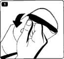
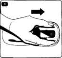
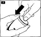
图14.1-14.5和图14.7-14.9示出了利用本发明的各个方面来施加可安装在表皮上的补片装置的过程;和Figures 14.1-14.5 and Figures 14.7-14.9 illustrate the process of applying an epidermis-mountable patch device utilizing aspects of the present invention; and
图15-图17示出了包装件的又一实施例。Figures 15-17 illustrate yet another embodiment of a package.
在各个幅图中,使用相似的附图标记表示相似的结构。In the various figures, like reference numerals are used to refer to like structures.
具体实施方式Detailed ways
当在下文中使用术语“上(upper)”和“下(lower)”、“右(right)”和“左(left)”、“水平(horizontal)”和“垂直(vertical)”或相似的相对表述方式时,这些术语仅指的是附图且并不一定指的是实际的使用状态。When the terms "upper" and "lower", "right" and "left", "horizontal" and "vertical" or similar relative When expressing means, these terms refer only to the drawings and do not necessarily refer to the actual state of use.
图1示出了包括被布置在包装件20中的可安装在表皮上的装置10的组件1。该装置包括被布置在柔性板片构件30上的相对刚性的本体部分14,所述柔性板片构件具有下部安装表面31,所述下部安装表面设有医用级粘结材料或组成物从而允许所述板片被粘结到经受对象的表皮表面上。该本体部分包括壳体部分12,所述壳体部分具有从其中延伸出来的两个滑动器腿部构件13(参见图7)。可具有单层结构或多层结构且可包括纺织或非纺织材料的板片构件具有比本体部分更大的覆盖区域,由此提供了从所述本体部分延伸出来的柔性周部部分32。该本体部分可通过任何适当方式例如通过焊接或粘结剂被附接到该板片构件上。FIG. 1 shows an
在所示实施例中,包装件以热成形泡罩包装件的形式存在,所述包装件形成了用于容纳该装置的腔体21。该包装件包括下部开口,当从所述包装件上去除所述可安装在表皮上的装置时,所述可安装在表皮上的装置可移动通过所述下部开口,所述开口限定出大体上的平面,且所述包装件包括围绕所述开口的圆周部分22。在所示实施例中,腔体对应于封闭装置的特定构型,即包括用于容纳所述本体部分的不对称的相对较深的中心腔体部分23和用于容纳所述板片构件的周部部分的相对较平的外州部分24,由此安装表面与所述大体上的平面基本上对应地被布置。该不对称腔体部分包括用于容纳该壳体的较深部分和用于容纳该腿部构件的不那么深的部分,上表面具有相对于包装件的长度取向而言倾斜的构型。In the embodiment shown, the package is in the form of a thermoformed blister pack forming a
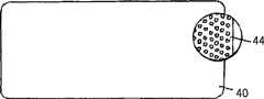
密封构件40被可释放地附接到包装件的圆周部分22上,由此提供用于该可安装在表皮上的装置的封闭空间。该密封构件可通过任何适当方式例如通过焊接或粘结剂被附接到该包装件上。在所示实施例中,密封构件具有被可释放地附接到所述粘结器件上的内表面41,由此所述密封构件还用作用于该粘结安装表面的保护性剥离衬里。密封构件可被消毒气体(例如环氧乙烷或干燥蒸汽)穿透,且具有部分地涂覆有使得易于从所述粘结器件(例如硅酮)上剥离该密封构件,同时仍允许消毒气体与未涂覆部分相对应地穿透密封构件并进入包装件内部,的材料。通过这种方式,提供了一种密封构件,所述密封构件在很大程度上具有这两种所需性质,即气体可穿透性,同时仍允许密封构件从所述粘结表面上被剥离。与经过涂覆的区域相对应地,涂层可限制或完全阻止气体穿透。在一个典型实施例中,密封构件由


该涂层可被施加形成不同构型。在第一实施例中,与用于板片构件的附接区域42相对应地施加该涂层,这样就留下了未涂覆区域43,所述未涂覆区域对应于介于该板片构件与包装件的该圆周部分之间的间隙(参见图2A)。在另一种可选实施例,按照精细图案(例如点状图案44)来施加涂层,该图案提供了允许消毒气体穿透密封构件,同时仍允许从安装表面上去除该密封构件,的表面(参见图2B)。可与用于板片构件的附接区域相对应地施加这种图案,或该图案可被施加到密封构件的整个内表面上,这允许将均匀涂覆的材料用于该密封构件。实际上,在后一种情况中,涂层不应妨碍密封构件材料被密封到包装件上的这种能力。如果并未完全阻止对应于该板片构件的该经过涂覆的区域的气体穿透性,且此外该板片构件和位于安装表面上的粘结剂在一定程度上允许气体穿透,则消毒工艺将不必依赖于通过介于板片构件与包装件之间的间隙而实现的气体进入。The coating can be applied to form different configurations. In the first embodiment, the coating is applied corresponding to the
图2C示出了一个实施例,其中柔性板片构件80具有两层构造,这包括被布置在主载体82(例如具有下部粘结表面的可透过的柔性聚氨酯材料)上的上部柔性薄膜81(例如具有下部粘结表面的可透过的聚氨酯膜)。为了将这些部件适当焊接在一起,该膜可包括一个或多个开口84,所述一个或多个开口允许本体13与该开口相对应地被直接焊接到所述载体上。除了下部释放衬里85以外,还设置了上部圆周释放衬里86以便在安装到表皮表面上的过程中支承该薄膜。2C shows an embodiment in which the
在图3中,示出了一个实施例50,其中使用了独立的密封构件60和剥离衬里70。该衬里和密封构件可被布置成使得自动剥离该密封构件会导致衬里被剥离下来,这与安装表面所处的位置无关。In Fig. 3, an embodiment 50 is shown wherein a separate sealing member 60 and release liner 70 are used. The liner and sealing member may be arranged such that automatic peeling of the sealing member results in the liner being peeled off regardless of where the mounting surface is located.
图4示出了包装件的一个实施例100,该包装件设有一组相对的附接器件101,所述附接器件允许包括协同作用的附接器件的可安装在表皮上的装置被安装在包装件的内部腔体中并被可释放地附接到其上。该包装件具有与图1所示包装件大体上相同的构型,包括不对称的相对较深的中心部分123、相对较平的外周部分124和圆周部分122。在包装件的每侧上,设置了较浅的凹陷部105,在该凹陷部上布置了以圆形内凸凸部101的形式存在的附接器件,两个凹陷部提供了第一握持器件。通过将包装件附接到封闭的可安装在表皮上的装置上,包装件可被用作用于将所包含的装置施加到表皮表面上的施加器。该包装件进一步包括位于上表面上的多个凹陷部,所述多个凹陷部形成了箭头形式的标记106。包装件的该区域还可用作释放器件从而使得压下该释放器件会导致具有该凸部的侧表面被提升而远离沟槽,由此释放了装置与包装件之间的附接。Figure 4 shows an
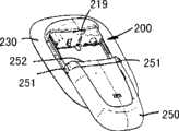
图5以X射线的透视表示方式示出了包括与图4所示包装件属于相同类型的包装件100的组件150,其中布置了以补片单元200的形式存在的可安装在表皮上的装置,所述包装件腔体被密封构件170封闭。密封构件可以是如图1所示的组合密封构件或如图3所示的独立密封构件。补片单元200具有与图1所示构型大体上相同的构型,然而,该补片单元设有以适于与包装件的凸部101协同作用的一组相对沟槽220的形式存在的附加附接器件。如图6所示,沟槽具有第一端221,在被提供给使用者的初始位置处,凸部101被布置在该第一端中,且所述沟槽具有第二端222。当沿壳体部分的方向推动包装件时,凸部将在沟槽中滑动直至其与第二端结合,在所述点处,所述凸部向外受力且因此与该沟槽脱离接合且包装件将从装置上被拆下。从例如图5中可以看出,朝向远离腿部构件213的方向的壳体部分的部分212被布置在极接近所述包装件的位置处,这防止了包装件沿相反方向滑动。实际上,在另一种可选构型中,附接器件可被构造成通过沿一个以上的方向移动包装件,例如前后移动包装件,而被释放。FIG. 5 shows in an X-ray perspective representation an
图7更详细地示出了补片单元200。该补片单元包括被布置在柔性板片构件230上的相对刚性的本体部分214,所述柔性板片构件具有下部安装表面231,所述下部安装表面设有允许该板片被粘结到经受对象的表皮表面上的粘结剂。该板片构件包括中心开口232,套管可被插置通过所述中心开口。该本体部分包括壳体部分212,套管插入机构被布置在所述壳体部分中,参见下文。该本体部分进一步包括从所述壳体延伸出来的两个滑动器腿部构件213,所述腿部增加了该补片的强度且当泵/贮存装置单元被附接到该补片单元上时进一步用作导引器件,参见下文。该壳体设有一组相对沟槽220,所述一组相对沟槽用作用于包装件且随后用于泵单元的附接器件。该壳体进一步包括适于被安装成与来自附接的泵单元250(参见图9)的相应的流体出口流体连通的流体入口215、用于对该附接的泵上的电触点进行致动的致动器216、和当泵单元第一次被附接时适于释放套管插入机构的释放构件217,所述套管被插置通过开口232。壳体部分212还包括适于与泵单元上相应的联接结构252相接合的掣子219。如图所示,当套管951被插入时,其受到泵单元的保护,然而,可去除该泵单元以便随后检查插入位点,如图8所示。Fig. 7 shows the
图9示出了补片单元200,其中泵单元250与所述补片单元部分地附接,且图10示出了被完全但以可释放的方式附接的泵单元。为了从补片单元上释放泵单元,使用者压下泵单元上的一组旋钮251,这使联接“桥”252略微升高而远离补片单元壳体上的掣子219。Figure 9 shows the
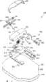
图11示意性地示出了经皮装置单元(此处为套管单元)的上部分解视图,所述经皮装置单元包括用于插入软套管的机构。更特别地,该单元包括底部部分910,底盘部分920被安装到所述底部部分上,由此形成内部,机构的不同部分被布置在该内部中。除了底部部分和底盘部分的功能性部分以外,该机构包括针保持器930、套管保持器940和中空套管组件,所述针保持器具有针座931,针932被安装到所述针座上,所述套管保持器包括适于与该针保持器接合的第一握持部分941和第二握持部分942,所述中空套管组件包括软的柔性套管,所述软的柔性套管具有远端部分951、中间部分952和近端部分953,该套管组件进一步包括适于与该底盘部分中的开口922接合的管形壳体构件955、其中安装有套管的近端端部的弹性体管形构件956以及可被针刺穿的弹性体隔膜,该管形构件和隔膜被布置在该壳体构件中从而由此提供用于该中空套管的流体入口孔口。该机构进一步包括由线圈形成的扭簧960,所述扭簧包括具有弯曲远端962的致动器臂961,该弹簧被布置在弹簧保持器970中,所述弹簧保持器包括掣子971,所述掣子允许弹簧在预拉伸状态下被安装。提供了释放构件975,所述释放构件包括当例如安装泵单元时适于与该泵单元接合的外端部分976和适于与该致动器臂接合并从该弹簧保持器上释放该致动器臂的内端部分977。该底部部分包括倾斜表面914,所述倾斜表面具有导引装置912,所述导引装置包括与单元的纵向轴线相对应地被布置的第一导引沟槽913和相对于该第一导引沟槽呈45度角度进行布置的第二导引沟槽914。Figure 11 schematically shows an upper exploded view of a transcutaneous device unit, here a cannula unit, comprising a mechanism for inserting a soft cannula. More particularly, the unit comprises a
在组装状态下,套管保持器在握持部分941、942被布置在针座931的每侧上的情况下被安装在针保持器上,这允许套管保持器沿针保持器的长度进行滑动,这两个保持器由此形成了插入器。在初始状态下,套管的远端部分被定位在针中且中间部分被定位于在该针保持器与该套管保持器之间形成的通道中,该套管借助于位于第一握持部分上的柔性构件被安装到套管保持器上。In the assembled state, the cannula holder is mounted on the needle holder with
在组装状态下,其上安装有套管保持器的针保持器被布置在该倾斜表面上且允许该针保持器上下滑动,且导引沟槽适于与被布置在套管保持器的下表面上的导引构件(未示出,参见例如图24)接合。为了控制针保持器的移动,针座包括导引部分933,所述导引部分具有两条相对沟槽,所述两条相对沟槽适于与被布置在底盘部分的内表面上相应的导引构件921相接合。如图所示,在该示意图中示出了没有切去部分的倾斜表面914,所述切去部分允许释放构件975和弹簧保持器970被安装(参见下文)。In the assembled state, the needle holder on which the cannula holder is installed is arranged on the inclined surface and allows the needle holder to slide up and down, and the guide groove is adapted to be arranged under the cannula holder. Guide members (not shown, see eg FIG. 24 ) on the surface engage. In order to control the movement of the needle holder, the needle hub includes a
底部部分910进一步包括两个相对的腿部部分918,每个所述腿部部分具有耳垂形件919,当底部部分被安装到柔性板片或箔片构件901上时,该耳垂形件提供了附接点,所述柔性板片或箔片构件包括粘结性下部安装表面904,所述粘结性下部安装表面允许经皮单元被安装在经受对象的表皮表面上。该板片构件包括中心开口903以及释放衬里902,针和套管被引导通过该中心开口。盖部分905用来封闭内部,由此形成大体上封闭的壳体。The
参见图12A-图12D,图中示出了处于部分组装状态的结合图11所述的机构,图中并未示出底盘部分和套管的近端部分。组装起来的实施例与上述实施例略微不同,然而,由于这种差别较小,因此将使用相同的附图标记。Referring to Figures 12A-12D, the mechanism described in connection with Figure 11 is shown in a partially assembled state, without showing the chassis portion and the proximal portion of the sleeve. The assembled embodiment differs slightly from the one described above, however, since this difference is minor, the same reference numerals will be used.
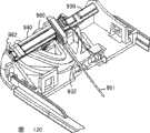
组装起来的实施例与图11所示实施例的主要不同之处在于:倾斜表面914已被多个壁构件取代、这些壁构件的上表面相结合地提供了使针保持器被布置在其上的倾斜“表面”,这允许弹簧960和释放构件975如图所示地在功能性方面正确地被布置。The main difference between the assembled embodiment and the embodiment shown in Figure 11 is that the
图12A示出了处于初始状态的组件,针保持器930处于第一(或初始)缩回位置且针相应的处于其缩回位置且尖锐远端被布置在壳体内。套管保持器与针保持器的缩回位置相对应地被定位在针保持器上的最右位置处。套管的远端部分被定位在针中,且该远端端部恰位于针的远端端部内,且中间部分被定位于在针保持器与套管保持器之间形成的通道中(参见图24),套管被柔性壁握持,所述柔性壁被成形为第一握持构件941的一部分。Figure 12A shows the assembly in an initial state, with the
当泵单元(未示出)被附接到套管单元上时,泵单元与释放构件975的外端部分976接合并推动所述外端部分,由此释放弹簧致动器臂961。致动器随后开始沿顺时针方向旋转(如图所示)并与针构件的后表面接合而将该针构件向前推至如图12B所示的该针构件的延长位置。在该移动过程中,针保持器通过与被布置在底盘部分的内表面上的导引构件921相接合而以线性方式被导引,而该套管相应地通过与第一导引沟槽913相结合而以线性方式被导引至其第一延长位置。因此,在该向前移动过程中,套管保持器并不相对于针保持器移动。When a pump unit (not shown) is attached to the cannula unit, the pump unit engages and pushes the
在该位置处,针保持器不能进一步向前移动,且当弹簧致动器臂继续沿顺时针方向旋转时,其与被布置在套管保持器的下表面上的导引构件(未示出,参见图24)相接合,由此开始使套管保持器向左移动,在针保持器上滑动。在该位置处,导引构件已经到达第一导引沟槽的下端(参见图11)且现在移动进入第二倾斜导引沟槽内,其中该导引构件沿导引沟槽向上移动,由此进一步向左移动。当套管保持器被附接到针保持器上时,针保持器也向上移动,然而,该针保持器由于与导引构件921相接合而以线性方式向后被导引。当套管保持器已经到达第二导引沟槽的上端时,其已经到达其第二延长位置,此时针保持器恰已到达其第二缩回位置(第一缩回位置与第二缩回位置可以是相同的),此时套管保持器恰已到达其第二延长位置。In this position, the needle holder cannot move further forward, and as the spring actuator arm continues to rotate clockwise, it cooperates with a guide member (not shown) arranged on the lower surface of the cannula holder. , see FIG. 24 ) engage, thereby beginning to move the cannula holder to the left, sliding over the needle holder. At this position, the guide member has reached the lower end of the first guide groove (see Figure 11) and is now moved into the second inclined guide groove, wherein the guide member moves upward along the guide groove, by This moves further to the left. When the cannula holder is attached to the needle holder, the needle holder also moves upwards, however, the needle holder is guided backwards in a linear fashion due to engagement with the
如上文所述,套管的远端部分初始被布置在针内、中间部分被布置于在套管与针保持器之间形成的通道中、且远端部分用作介于移动插入器与流体入口孔口之间的柔性连接件。当套管与该中间部分的近端端部相对应地被附接到套管保持器上时,套管保持器向左进行的移动将会将套管推动通过该通道、围绕使通道与针相连的弯曲部移动、且向下进入该针内。因此,当套管保持器从其第一延长位置移动至其第二延长位置时,套管被推出而通过该针,而与此同时,针保持器与针一起被缩回(参见图12C)。在套管和针以相同速度分别延长和缩回时(这对应于第二导引沟槽是直的且相对于第一导引沟槽呈45度的角度被布置的这种状态),则延长套管的远端部分将不会相对于壳体进行移动,而针则将被缩回。As described above, the distal portion of the cannula is initially disposed within the needle, the middle portion is disposed in the channel formed between the cannula and the needle holder, and the distal portion serves as a mediator between the moving inserter and the fluid. Flexible connection between inlet orifices. When the cannula is attached to the cannula holder corresponding to the proximal end of the intermediate portion, movement of the cannula holder to the left will push the cannula through the passage, around the passage and the needle. The connected bends move and descend into the needle. Thus, when the cannula holder is moved from its first extended position to its second extended position, the cannula is pushed out through the needle while at the same time the needle holder is retracted together with the needle (see Figure 12C) . When the cannula and needle are respectively extended and retracted at the same speed (this corresponds to the state in which the second guide groove is straight and arranged at an angle of 45 degrees relative to the first guide groove), then The distal portion of the extension sheath will not move relative to the housing and the needle will be retracted.
为了允许套管保持器的导引构件适当地进入第二导引沟槽,可能希望使两条导引沟槽与短的沟槽部分相连,这使得在针开始缩回之前套管将作少量延伸,这如图12D所示。相应地,通过改变第二导引沟槽的构型,有可能使套管从其最延长的位置处少量缩回。后一种情况可能是希望出现的,从而从在插入过程中形成的任何组织塞(tissue plug)中释放出远端套管开口。In order to allow the guide member of the cannula holder to properly enter the second guide groove, it may be desirable to connect the two guide grooves with a short groove portion so that the cannula will travel a small amount before the needle begins to retract. extended, as shown in Figure 12D. Accordingly, by changing the configuration of the second guide groove, it is possible to retract the sleeve by a small amount from its most extended position. The latter situation may be desirable to free the distal cannula opening from any tissue plug formed during insertion.
图13示出了与图9所示泵单元属于相同类型的泵单元300的分解视图。该泵单元包括上部壳体部分310和下部壳体部分320,这两个壳体部分在组装状态下提供了用于贮存装置单元的附加部件的防水封闭装置,所述附加部件为:泵组件330、致动器340、贮存装置350和电子控制器件360。在被提供给用户的初始状态下,保护性盖帽组件370被附接到该单元上。FIG. 13 shows an exploded view of a
下部壳体部分由透明材料制成,所述透明材料允许使用者从外部检查贮存装置(参见下文),且所述下部壳体部分包括开口321,排水口322被布置在所述开口中。具有窗开口326的板片构件325被附接到下部壳体部分的下表面上,这使得除了贮存装置上的窗以外的透明部分都被遮住。该板片构件可用来显示使用者信息,例如药物的类型和量。The lower housing part is made of a transparent material which allows a user to inspect the storage device from the outside (see below) and which comprises an
泵组件330以隔膜泵的形式存在,所述隔膜泵包括由活塞致动的泵隔膜,所述泵隔膜具有控流入口阀和出口阀。该泵具有大体上成层的构造,所述构造包括多个本体构件,在所述多个本体构件之间插置有柔性膜层,由此可形成泵室、入口阀和出口阀以及一个或多个安全阀。层与夹持件338被保持在一起。该泵进一步包括以被可滑动地定位在泵内(为说明目的起见,图中示出的是位于泵外部的情况)的中空连接针的形式存在的流体连接器335,这使得当该保护性盖帽组件370被致动时允许泵与贮存装置相连。为了获得对这种隔膜泵的更详细的描述,可参见本申请人的共同待审的申请PCT/EP 2006/060277,所述申请在此作为参考被引用。The
泵致动器以线圈致动器(coil actuator)的形式存在,泵组件通过夹持件被附接到所述线圈致动器上。为了获得对这种线圈致动器的更详细的描述,可参见本申请人的共同待审的申请WO 2005/094919,所述申请在此作为参考被引用。The pump actuator is in the form of a coil actuator to which the pump assembly is attached by means of a clamp. For a more detailed description of such a coil actuator, reference is made to the applicant's co-pending application WO 2005/094919, which is hereby incorporated by reference.
药物贮存装置以柔性的经过预充注的可叠缩袋350的形式存在,所述可叠缩袋包括针可穿透的隔膜351,所述隔膜允许流体连接器被推入贮存装置内而不会产生泄漏,由此提供与泵的流体连通。夹钳保持器352被附接到该贮存装置上,这允许该贮存装置被附接到壳体上,同时不会影响该贮存装置本身。在该贮存装置下面(正如从单元的下表面所看到地那样)布置了板片(未示出),所述板片包括对比增强图案,例如位于白背景上的黑线,从而使得易于通过目视而识别药物中的杂质,例如胰岛素中的纤丝化现象。The drug storage device is in the form of a flexible pre-filled
电子控制器件360包括具有用于控制泵组件的处理器361的印刷电路板或柔性印刷件362、蓄电池366、为使用者提供报警信号和连通界面的声换能器365、以及被安装在致动器上的触点,当首次使用该控制器件时,该触点允许使用者对控制器件进行致动(借助于致动器216)。该控制器件可包括接收器和/或传送器,从而允许贮存装置与遥控器无线连通。The
保护性盖帽组件370包括初始地被锁定到贮存装置单元上的附接构件371和被滑动地附接到所述附接构件上的启动“按钮”构件372。当从该贮存装置单元最初的包装件(未示出)上去除该贮存装置单元时,使用者朝向该贮存装置单元压下致动构件。该致动导致发生三种动作:位于致动构件上的第一凸部将对贮存装置单元上的触点进行致动,这导致电子器件被启动,且第二凸部将与泵组件接合并将流体连接器335从泵组件中推出且推入贮存装置内,由此在贮存装置与泵之间形成流体连通。第三,压下启动构件将使附接构件被“解锁”并允许该附接构件且由此允许该启动构件从贮存装置单元中被去除。其后,贮存装置单元可被连接至补片单元。
参见图14.1-14.5和图14.7-14.9,下面将对利用本发明的各个方面来施加可安装在表皮上的补片装置的过程进行描述。该描述被部分地草拟为用户手册的指令。(1)拉开位于施加器(即包装件)的背面上的保护纸。确保将施加器留在该补片上,因为您将会需要该施加器来准确地附接该补片(参见图14.1)。(2)去除补片上的两片包装纸-一次去除一片(该包装纸对应于图2中的剥离衬里70)(参见图14.2)。(3)竖立起该补片并在沿施加箭头方向进行的滚动运动中将该补片附接在下腹部上。一旦该补片被附接,则将该补片压靠在表皮上(参见图14.3)。(4)使施加器沿箭头方向滑动离开该补片(通过该运动使得凸部101将在沟槽220中滑动;当所述凸部到达沟槽的第二端222时,该凸部将被升高而离开该沟槽且施加器将从补片单元上被拆下。另一种可选方式是,可通过略微旋转或扭转该施加器来对该附接器件进行解锁)。该施加器可被丢弃(参见图14.4)。(5)通过让您的手指轻柔地穿过边缘且在滑动器之间穿过而使该补片在表皮上变得平滑(参见图14.5)。(6)从泵单元的包装件中去除泵单元。(7)下压该保护性盖帽以使泵单元处于备用状态(参见图14.6)。(8)按压并保持泵上的释放按钮。去除该保护性盖帽(参见图14.8)。(9)将泵单元滑动到补片上。当您感觉到喀哒一下且泵发出嘟嘟声时,泵已被正确连接。软套管自动进入表皮(参见图14.9)。Referring to Figures 14.1-14.5 and Figures 14.7-14.9, the process of applying an epidermis-mountable patch device utilizing various aspects of the present invention will now be described. The description was drafted in part as instructions for the user manual. (1) Pull off the protective paper located on the back of the applicator (ie, the package). Make sure to leave the applicator on the patch as you will need it to attach the patch accurately (see Figure 14.1). (2) Remove two wrappers on the patch - one at a time (the wrapper corresponds to release liner 70 in Figure 2) (see Figure 14.2). (3) The patch is erected and attached to the lower abdomen in a rolling motion in the direction of the application arrow. Once the patch is attached, the patch is pressed against the epidermis (see Figure 14.3). (4) Slide the applicator away from the patch in the direction of the arrow (by this movement the
正如上面结合图1所述地那样,柔性板片30、80可具有不同设计。下面将给出多个实例。As mentioned above in connection with FIG. 1, the
实例1:位于柔性的可透过的聚氨酯膜(Bioflex 25μ)上的2区域水状胶体粘结剂。Example 1 : 2-zone hydrocolloid adhesive on a flexible permeable polyurethane membrane (Bioflex 25μ).
实例2:位于柔性的可透过的聚氨酯膜(Bioflex 25μ)上的基于聚丙二醇的粘结剂。Example 2: Polypropylene glycol based adhesive on a flexible permeable polyurethane membrane (Bioflex 25μ).
实例3:来自BSN medical的Fixomull Stretch-位于结构化聚酯非织造制品上的丙烯酸粘结剂。Example 3: Fixomull Stretch from BSN medical - Acrylic adhesive on structured polyester nonwoven.
实例4:以下材料的双层构造(参见图2C):3M/9832-位于柔性的可透过的聚氨酯薄膜上的丙烯酸粘结剂,以及3M/9904-位于可透过的柔性聚氨酯非织造制品上的丙烯酸粘结剂。Example 4: Two-layer construction of the following materials (see Figure 2C): 3M/9832 - acrylic adhesive on a flexible permeable polyurethane film, and 3M/9904 - on a permeable flexible polyurethane nonwoven Acrylic adhesive on.
在从边缘上被剥离下来的实例中,有可能通过利用以粘结环形式存在的“修补成套件”以便进行二次固定从而延长该可安装在表皮上的装置的运行寿命,该粘结环例如为来自Smith & Nephew的Opsite-Flexifix,一种位于具有有利的支承背衬的柔性的可透过的聚氨酯薄膜上的丙烯酸粘结剂。In the case of peeling off from the edge, it is possible to prolong the operational life of the skin-mountable device by utilizing a "repair kit" in the form of an adhesive ring for secondary fixation An example is Opsite-Flexifix from Smith & Nephew, an acrylic adhesive on a flexible, permeable polyurethane film with an advantageous support backing.
参见图15-17,下面将对包装件400的又一实施例进行描述,该包装件具有与结合图1所述的包装件大体上相同的构型。更具体而言,该包装件包括不对称的相对较深的中心部分423、相对较平的外周部分424和圆周部分422,所述中心部分具有位于上表面的一端处的标记406。在该包装件的每侧上,设置了较浅的凹陷部405,在该凹陷部上布置了以圆形内凸凸部401的形式存在的附接器件,两个凹陷部提供了第一握持器件。与上述实施例相反地,该包装件具有另一种可选的上表面构型,其中构造出大体上倾斜的表面以便允许两个组件以如图17所示的阴阳方式被布置在彼此顶上。该构型允许两个包装件以紧凑且因此具有成本效率的方式被布置在彼此上。为了进一步确保包装件在例如操控和运输过程中被“锁定”而彼此接合,该上表面在一端处设有凸部407,该凸部适于与相对的包装件的标记相接合。Referring to Figures 15-17, yet another embodiment of a
在上面对优选实施例进行的描述中,已经在足以使本领域的技术人员易于理解本发明概念的程度上对为不同部件提供了所述功能性的不同结构和器件作出了说明。用于这些不同部件的详细构造和说明被认为是由本领域的技术人员按照本说明书中所述的工艺路线所实施的正常设计过程的目标。In the above description of the preferred embodiments, the different structures and devices providing the described functionality to the different components have been illustrated to an extent sufficient for those skilled in the art to easily understand the inventive concept. The detailed construction and specification for these various components is considered to be the object of a normal design process carried out by those skilled in the art along the lines described in this specification.
Claims (12)
Translated fromChineseApplications Claiming Priority (2)
| Application Number | Priority Date | Filing Date | Title |
|---|---|---|---|
| EP06113146 | 2006-04-26 | ||
| EP06113146.2 | 2006-04-26 |
Publications (1)
| Publication Number | Publication Date |
|---|---|
| CN101426542Atrue CN101426542A (en) | 2009-05-06 |
Family
ID=37057361
Family Applications (1)
| Application Number | Title | Priority Date | Filing Date |
|---|---|---|---|
| CNA2007800145600AWithdrawnCN101426542A (en) | 2006-04-26 | 2007-04-23 | Skin-mountable device in packaging comprising coated seal member |
Country Status (4)
| Country | Link |
|---|---|
| US (1) | US20090163874A1 (en) |
| EP (1) | EP2012852A1 (en) |
| CN (1) | CN101426542A (en) |
| WO (1) | WO2007122207A1 (en) |
Families Citing this family (62)
| Publication number | Priority date | Publication date | Assignee | Title |
|---|---|---|---|---|
| ATE392223T1 (en) | 2003-05-08 | 2008-05-15 | Novo Nordisk As | INTERNAL NEEDLE INTRODUCER |
| EP1475113A1 (en) | 2003-05-08 | 2004-11-10 | Novo Nordisk A/S | External needle inserter |
| JP4509100B2 (en)* | 2003-05-08 | 2010-07-21 | ノボ・ノルデイスク・エー/エス | Infusion device attachable to skin with removable needle insertion actuation |
| EP1502613A1 (en)* | 2003-08-01 | 2005-02-02 | Novo Nordisk A/S | Needle device with retraction means |
| KR20060099520A (en)* | 2003-10-21 | 2006-09-19 | 노보 노르디스크 에이/에스 | Medical Skin Mounting Device |
| MXPA06010784A (en) | 2004-03-26 | 2006-12-15 | Unomedical As | Injector device for infusion set. |
| CN100586495C (en)* | 2004-03-30 | 2010-02-03 | 诺和诺德公司 | Actuator system comprising lever mechanism |
| WO2005124918A2 (en) | 2004-06-14 | 2005-12-29 | Massachusetts Institute Of Technology | Electrochemical actuating methods, devices and structures |
| US7999435B2 (en)* | 2004-06-14 | 2011-08-16 | Massachusetts Institute Of Technology | Electrochemical actuator |
| US7872396B2 (en) | 2004-06-14 | 2011-01-18 | Massachusetts Institute Of Technology | Electrochemical actuator |
| US7994686B2 (en)* | 2004-06-14 | 2011-08-09 | Massachusetts Institute Of Technology | Electrochemical methods, devices, and structures |
| US8247946B2 (en) | 2004-06-14 | 2012-08-21 | Massachusetts Institute Of Technology | Electrochemical actuator |
| US8062250B2 (en) | 2004-08-10 | 2011-11-22 | Unomedical A/S | Cannula device |
| EP1804859A1 (en)* | 2004-09-22 | 2007-07-11 | Novo Nordisk A/S | Medical device with cannula inserter |
| WO2006032689A1 (en)* | 2004-09-22 | 2006-03-30 | Novo Nordisk A/S | Medical device with transcutaneous cannula device |
| EP1824536B1 (en)* | 2004-12-06 | 2009-08-26 | Novo Nordisk A/S | Ventilated skin mountable device |
| US8167841B2 (en) | 2005-01-24 | 2012-05-01 | Novo Nordisk A/S | Transcutaneous device assembly |
| CN101175516B (en)* | 2005-05-13 | 2011-02-16 | 诺和诺德公司 | Medical device suitable for detecting detachment of a percutaneous device |
| EP1762259B2 (en) | 2005-09-12 | 2025-01-01 | Unomedical A/S | Inserter for an infusion set with a first and second spring units |
| DK1962926T3 (en) | 2005-12-23 | 2009-09-28 | Unomedical As | injection device |
| WO2007098771A2 (en) | 2006-02-28 | 2007-09-07 | Unomedical A/S | Inserter for infusion part and infusion part provided with needle protector |
| EP1997233B1 (en)* | 2006-03-13 | 2014-03-05 | Novo Nordisk A/S | Secure pairing of electronic devices using dual means of communication |
| CN101401314B (en)* | 2006-03-13 | 2013-04-24 | 诺沃-诺迪斯克有限公司 | Medical system with dual purpose communication device comprising first and second units |
| EP2032188A1 (en) | 2006-06-06 | 2009-03-11 | Novo Nordisk A/S | Assembly comprising skin-mountable device and packaging therefore |
| CA2653631A1 (en) | 2006-06-07 | 2007-12-13 | Unomedical A/S | Inserter |
| CA2653764A1 (en) | 2006-06-09 | 2007-12-13 | Unomedical A/S | Mounting pad |
| JP2009545341A (en) | 2006-08-02 | 2009-12-24 | ウノメディカル アクティーゼルスカブ | Cannula and delivery device |
| EP1917990A1 (en) | 2006-10-31 | 2008-05-07 | Unomedical A/S | Infusion set |
| DK3632488T3 (en)* | 2006-12-22 | 2023-06-06 | Hoffmann La Roche | Device for continuous administration of a therapeutic fluid |
| JP2010520409A (en)* | 2007-03-06 | 2010-06-10 | ノボ・ノルデイスク・エー/エス | Pump assembly with actuator system |
| EP2155311B1 (en) | 2007-06-20 | 2013-01-02 | Unomedical A/S | A method and an apparatus for making a catheter |
| AU2008270327A1 (en) | 2007-07-03 | 2009-01-08 | Unomedical A/S | Inserter having bistable equilibrium states |
| DE602008005153D1 (en) | 2007-07-10 | 2011-04-07 | Unomedical As | INSERT WITH TWO SPRINGS |
| EP2178584A2 (en)* | 2007-07-26 | 2010-04-28 | Entra Pharmaceuticals Inc. | Skin-patch pump comprising a changing-volume electrochemical actuator |
| CN101888859B (en)* | 2007-10-31 | 2014-09-17 | 诺沃-诺迪斯克有限公司 | Non-porous material as sterilization barrier |
| ATE522240T1 (en) | 2008-02-13 | 2011-09-15 | Unomedical As | SEAL BETWEEN A CANNULAR PART AND A FLUID PATH |
| US9566384B2 (en) | 2008-02-20 | 2017-02-14 | Unomedical A/S | Insertion device with horizontally moving part |
| BRPI0919548A2 (en)* | 2008-09-29 | 2015-12-08 | Unomedical As | insert package |
| AU2009331635A1 (en) | 2008-12-22 | 2011-06-23 | Unomedical A/S | Medical device comprising adhesive pad |
| AU2010277755A1 (en) | 2009-07-30 | 2012-02-02 | Unomedical A/S | Inserter device with horizontal moving part |
| KR20120047896A (en) | 2009-08-07 | 2012-05-14 | 우노메디컬 에이/에스 | Delivery device with sensor and one or more cannulas |
| KR20130018783A (en) | 2010-03-30 | 2013-02-25 | 우노메디컬 에이/에스 | Medical device |
| WO2011140359A2 (en) | 2010-05-05 | 2011-11-10 | Springleaf Therapeutics, Inc. | Systems and methods for delivering a therapeutic agent |
| EP2433663A1 (en) | 2010-09-27 | 2012-03-28 | Unomedical A/S | Insertion system |
| EP2436412A1 (en) | 2010-10-04 | 2012-04-04 | Unomedical A/S | A sprinkler cannula |
| EP2436311A1 (en)* | 2010-10-04 | 2012-04-04 | PharmaSens AG | Diagnostic device |
| WO2012083174A2 (en) | 2010-12-17 | 2012-06-21 | Massachusetts Institute Of Technology | Electrochemical actuators |
| WO2013050277A1 (en) | 2011-10-05 | 2013-04-11 | Unomedical A/S | Inserter for simultaneous insertion of multiple transcutaneous parts |
| US20130090633A1 (en)* | 2011-10-07 | 2013-04-11 | University Of Southern California | Osmotic patch pump |
| EP2583715A1 (en) | 2011-10-19 | 2013-04-24 | Unomedical A/S | Infusion tube system and method for manufacture |
| US9440051B2 (en) | 2011-10-27 | 2016-09-13 | Unomedical A/S | Inserter for a multiplicity of subcutaneous parts |
| EP2650031A1 (en)* | 2012-04-11 | 2013-10-16 | PharmaSens AG | Manual pressure activated application mechanism |
| EP2650032A1 (en)* | 2012-04-11 | 2013-10-16 | PharmaSens AG | Subcutaneous needle insertion mechanism |
| WO2015122964A1 (en)* | 2014-02-11 | 2015-08-20 | Dexcom, Inc. | Packaging system for analyte sensors |
| PL3097933T3 (en) | 2015-05-26 | 2020-03-31 | F. Hoffmann-La Roche Ag | Cartridge and inserter for a medical system |
| EP3199121B1 (en) | 2016-01-29 | 2018-08-22 | Roche Diabetes Care GmbH | Functional medical package and medical device for inserting at least one subsystem into a host |
| KR101928297B1 (en)* | 2016-09-08 | 2018-12-12 | 이오플로우(주) | Medical fluid delivery device |
| CN119950880A (en) | 2017-05-05 | 2025-05-09 | 里珍纳龙药品有限公司 | Auto-injectors and related methods of use |
| CN113164678B (en)* | 2019-03-13 | 2023-02-17 | 泰尔茂株式会社 | drug delivery device |
| KR102549236B1 (en)* | 2019-11-25 | 2023-06-30 | 한국전자통신연구원 | Apparatus and method for measuring blood sugar |
| EP3967338A1 (en) | 2020-09-09 | 2022-03-16 | Ypsomed AG | Patch injection device with an improved release liner removal |
| USD1007676S1 (en) | 2021-11-16 | 2023-12-12 | Regeneron Pharmaceuticals, Inc. | Wearable autoinjector |
Family Cites Families (109)
| Publication number | Priority date | Publication date | Assignee | Title |
|---|---|---|---|---|
| US55711A (en)* | 1866-06-19 | Improvement in hydrants | ||
| US123740A (en)* | 1872-02-13 | Improvement in bracelets | ||
| US6241704B1 (en)* | 1901-11-22 | 2001-06-05 | Sims Deltec, Inc. | Drug pump systems and methods |
| US858001A (en)* | 1905-02-07 | 1907-06-25 | Mortimer A Howe | Separable double letter-sheet. |
| US2605765A (en)* | 1947-06-05 | 1952-08-05 | Kollsman Paul | Automatic syringe |
| US2980032A (en)* | 1959-02-27 | 1961-04-18 | Brown Engine Products Inc | Fuel pump |
| US4016879A (en)* | 1973-08-22 | 1977-04-12 | Dynasciences Corporation | Multi-mode cannulating apparatus |
| US4245634A (en)* | 1975-01-22 | 1981-01-20 | Hospital For Sick Children | Artificial beta cell |
| DE2513467C3 (en)* | 1975-03-26 | 1979-10-31 | Siemens Ag, 1000 Berlin Und 8000 Muenchen | Device for infusing liquids into the human or animal body |
| US4137020A (en)* | 1976-12-26 | 1979-01-30 | Nippondenso Co., Ltd. | Diaphragm type air pump |
| US4262824A (en)* | 1978-02-17 | 1981-04-21 | Baxter Travenol Laboratories, Inc. | Low-current E-frame electronic magnet with a permanent magnet armature for an I. V. valving controller |
| DE2929813A1 (en)* | 1979-07-23 | 1981-01-29 | Hoelzle & Chelius Kg | METHOD FOR DISMOUNTING FLOWABLE MEDIA AND DEVICE FOR IMPLEMENTING THE METHOD |
| US4402407A (en) | 1980-12-16 | 1983-09-06 | Maly George P | Sterilization chest |
| US4340048A (en)* | 1981-03-28 | 1982-07-20 | Alza Corporation | Self-driven hypodermic injector |
| US4399824A (en)* | 1981-10-05 | 1983-08-23 | Air-Shields, Inc. | Apparatus for detecting probe dislodgement |
| US4378015A (en)* | 1981-12-21 | 1983-03-29 | Wardlaw Stephen C | Automatic injecting syringe |
| US4529401A (en)* | 1982-01-11 | 1985-07-16 | Cardiac Pacemakers, Inc. | Ambulatory infusion pump having programmable parameters |
| US4753651A (en)* | 1982-08-30 | 1988-06-28 | Alza Corporation | Self-driven pump |
| US4519792A (en)* | 1982-12-06 | 1985-05-28 | Abbott Laboratories | Infusion pump system |
| US4552561A (en) | 1982-12-23 | 1985-11-12 | Alza Corporation | Body mounted pump housing and pump assembly employing the same |
| CA1221596A (en)* | 1984-03-09 | 1987-05-12 | David Evans | Surgical needle |
| US4657490A (en)* | 1985-03-27 | 1987-04-14 | Quest Medical, Inc. | Infusion pump with disposable cassette |
| US4755173A (en)* | 1986-02-25 | 1988-07-05 | Pacesetter Infusion, Ltd. | Soft cannula subcutaneous injection set |
| US5211201A (en)* | 1986-03-04 | 1993-05-18 | Deka Products Limited Partnership | Intravenous fluid delivery system with air elimination |
| US4734092A (en)* | 1987-02-18 | 1988-03-29 | Ivac Corporation | Ambulatory drug delivery device |
| US4994078A (en)* | 1988-02-17 | 1991-02-19 | Jarvik Robert K | Intraventricular artificial hearts and methods of their surgical implantation and use |
| US4894054A (en)* | 1988-06-20 | 1990-01-16 | Miskinyar Shir A | Preloaded automatic disposable syringe |
| US4928528A (en)* | 1988-07-25 | 1990-05-29 | Cordis Corporation | Arterial/venous simulator |
| US5008110A (en)* | 1988-11-10 | 1991-04-16 | The Procter & Gamble Company | Storage-stable transdermal patch |
| CA2033181C (en)* | 1989-06-14 | 2000-10-24 | Harald T. G. Van Lintel | Two valve micropump with improved outlet |
| US5122116A (en)* | 1990-04-24 | 1992-06-16 | Science Incorporated | Closed drug delivery system |
| US5527288A (en) | 1990-12-13 | 1996-06-18 | Elan Medical Technologies Limited | Intradermal drug delivery device and method for intradermal delivery of drugs |
| US5122201A (en)* | 1991-11-19 | 1992-06-16 | International Business Machines Corporation | Water-soluble solder flux |
| US5223433A (en)* | 1991-12-13 | 1993-06-29 | Diametrics Medical Inc. | Temperature stabilized fluid calibration system |
| DE4336336A1 (en)* | 1992-11-23 | 1994-05-26 | Lang Volker | Cassette infusion system |
| US5319950A (en)* | 1993-02-22 | 1994-06-14 | Kayser-Roth Corporation | Abrasion resistant reinforced fabric |
| US5336052A (en)* | 1993-04-28 | 1994-08-09 | Abel Pumpen Gmbh & Co. Kg | Viscous material pump |
| US5391950A (en) | 1993-06-24 | 1995-02-21 | Unisys Corporation | Circuit to eliminate signal chatter in the output of a fiber-optic receiver |
| US5485917A (en)* | 1993-12-06 | 1996-01-23 | Ethicon-Endo-Surgery | Quick release package for surgical instrument |
| US5390671A (en) | 1994-03-15 | 1995-02-21 | Minimed Inc. | Transcutaneous sensor insertion set |
| US5514095A (en)* | 1994-04-04 | 1996-05-07 | Haemonetics Corporation | Apparatus for heating, filtering and eliminating gas from biological fluids |
| US5482473A (en) | 1994-05-09 | 1996-01-09 | Minimed Inc. | Flex circuit connector |
| US5494415A (en)* | 1994-09-12 | 1996-02-27 | Morita; Yoshimitsu | Magnetically-driven pump |
| CA2159052C (en) | 1994-10-28 | 2007-03-06 | Rainer Alex | Injection device |
| US5568806A (en) | 1995-02-16 | 1996-10-29 | Minimed Inc. | Transcutaneous sensor insertion set |
| US5647853A (en)* | 1995-03-03 | 1997-07-15 | Minimed Inc. | Rapid response occlusion detector for a medication infusion pump |
| IE77523B1 (en) | 1995-09-11 | 1997-12-17 | Elan Med Tech | Medicament delivery device |
| US5776103A (en)* | 1995-10-11 | 1998-07-07 | Science Incorporated | Fluid delivery device with bolus injection site |
| ZA9610374B (en)* | 1995-12-11 | 1997-06-23 | Elan Med Tech | Cartridge-based drug delivery device |
| US5860952A (en)* | 1996-01-11 | 1999-01-19 | C. R. Bard, Inc. | Corporeal access tube assembly and method |
| US5720391A (en)* | 1996-03-29 | 1998-02-24 | St. Jude Medical, Inc. | Packaging and holder for heart valve prosthesis |
| US5776109A (en)* | 1996-08-23 | 1998-07-07 | Urrutia; Hector | Drip chamber for intravenous fluid delivery system |
| DE19802367C1 (en) | 1997-02-19 | 1999-09-23 | Hahn Schickard Ges | Microdosing device array and method for operating the same |
| US5928194A (en)* | 1997-04-07 | 1999-07-27 | Maget; Henri J. R. | Self-contained liquid microdispenser |
| US6530900B1 (en)* | 1997-05-06 | 2003-03-11 | Elan Pharma International Limited | Drug delivery device |
| US5913856A (en)* | 1997-05-19 | 1999-06-22 | Irvine Biomedical, Inc. | Catheter system having a porous shaft and fluid irrigation capabilities |
| US6558351B1 (en)* | 1999-06-03 | 2003-05-06 | Medtronic Minimed, Inc. | Closed loop system for controlling insulin infusion |
| US5954643A (en) | 1997-06-09 | 1999-09-21 | Minimid Inc. | Insertion set for a transcutaneous sensor |
| US6716192B1 (en)* | 1997-09-30 | 2004-04-06 | Charles F. Schroeder | Medical needle having a visibly marked tip |
| US6045534A (en)* | 1997-10-27 | 2000-04-04 | Sarcos, Inc. | Disposable fluid injection module |
| ATE302041T1 (en)* | 1997-12-11 | 2005-09-15 | Alza Corp | DEVICE FOR INCREASE THE TRANSDERMAL FLOW OF ACTIVE INGREDIENTS |
| US5957895A (en)* | 1998-02-20 | 1999-09-28 | Becton Dickinson And Company | Low-profile automatic injection device with self-emptying reservoir |
| US6554798B1 (en)* | 1998-08-18 | 2003-04-29 | Medtronic Minimed, Inc. | External infusion device with remote programming, bolus estimator and/or vibration alarm capabilities |
| US6358731B1 (en)* | 1999-10-20 | 2002-03-19 | Wei K. Hsu | Sterilizable cultivation system with separately attachable microfiltration membrane |
| CA2345439C (en)* | 1998-10-29 | 2005-08-09 | Minimed, Inc. | Compact pump drive system |
| WO2000029049A1 (en)* | 1998-11-13 | 2000-05-25 | Elan Pharma International Limited | Drug delivery systems and methods |
| DE19908438C2 (en)* | 1999-02-26 | 2003-05-15 | Cochlear Ltd | Device and method for supporting the positioning of an external transmitting part with respect to an implantable receiving part of a charging system of an implantable medical device |
| US6554791B1 (en)* | 1999-09-29 | 2003-04-29 | Smisson-Cartledge Biomedical, Llc | Rapid infusion system |
| US6577899B2 (en)* | 2000-01-21 | 2003-06-10 | Medtronic Minimed, Inc. | Microprocessor controlled ambulatory medical apparatus with hand held communication device |
| JP2001288309A (en)* | 2000-01-26 | 2001-10-16 | Tokuyama Corp | Flame retardant polyolefin composition |
| US6461329B1 (en)* | 2000-03-13 | 2002-10-08 | Medtronic Minimed, Inc. | Infusion site leak detection system and method of using the same |
| DE10029453C2 (en)* | 2000-06-21 | 2002-06-13 | Roche Diagnostics Gmbh | Pump for very low flow rates |
| US7530964B2 (en)* | 2000-06-30 | 2009-05-12 | Elan Pharma International Limited | Needle device and method thereof |
| US6589229B1 (en)* | 2000-07-31 | 2003-07-08 | Becton, Dickinson And Company | Wearable, self-contained drug infusion device |
| US6702779B2 (en) | 2000-08-18 | 2004-03-09 | Becton, Dickinson And Company | Constant rate fluid delivery device with selectable flow rate and titratable bolus button |
| CA2421133C (en)* | 2000-09-08 | 2012-06-26 | Insulet Corporation | Devices, systems and methods for patient infusion |
| US6669669B2 (en)* | 2001-10-12 | 2003-12-30 | Insulet Corporation | Laminated patient infusion device |
| CA2327012C (en)* | 2000-11-28 | 2006-09-26 | Duncan Wade | Diaphragm for a diaphragm pump |
| US7052483B2 (en)* | 2000-12-19 | 2006-05-30 | Animas Corporation | Transcutaneous inserter for low-profile infusion sets |
| DE10063242C2 (en)* | 2000-12-19 | 2003-02-20 | Siemens Ag | Communication terminal with antenna |
| EP1381408A4 (en)* | 2001-02-22 | 2007-06-13 | Insulet Corp | Modular infusion device and method |
| US6550493B2 (en)* | 2001-06-13 | 2003-04-22 | Baxter International Inc. | Vacuum demand valve |
| US20030088238A1 (en)* | 2001-09-26 | 2003-05-08 | Poulsen Jens Ulrik | Modular drug delivery system |
| US6830562B2 (en)* | 2001-09-27 | 2004-12-14 | Unomedical A/S | Injector device for placing a subcutaneous infusion set |
| US6613015B2 (en)* | 2001-10-04 | 2003-09-02 | Deltec, Inc. | Right angle safety needle |
| US8066678B2 (en)* | 2001-12-17 | 2011-11-29 | Bard Access Systems, Inc. | Safety needle with collapsible sheath |
| US6703252B2 (en)* | 2002-01-31 | 2004-03-09 | Hewlett-Packard Development Company, L.P. | Method of manufacturing an emitter |
| US6878136B2 (en)* | 2002-02-28 | 2005-04-12 | Medical Product Specialists | Huber needle with anti-rebound safety mechanism |
| US6692457B2 (en)* | 2002-03-01 | 2004-02-17 | Insulet Corporation | Flow condition sensor assembly for patient infusion device |
| FR2838721B1 (en)* | 2002-04-22 | 2004-12-03 | Becton Dickinson France | PACKAGE FOR USE IN CONVEYING OR STERILIZING OBJECTS |
| US6960192B1 (en) | 2002-04-23 | 2005-11-01 | Insulet Corporation | Transcutaneous fluid delivery system |
| ES2426255T3 (en)* | 2002-06-28 | 2013-10-22 | Boston Scientific Neuromodulation Corporation | Microstimulator that has a built-in power source and a two-way telemetry system |
| US20040116905A1 (en)* | 2002-09-09 | 2004-06-17 | Pedersen Per Elgard | Flow restrictor with safety feature |
| EP1403519A1 (en)* | 2002-09-27 | 2004-03-31 | Novo Nordisk A/S | Membrane pump with stretchable pump membrane |
| DE10255817A1 (en)* | 2002-11-29 | 2004-06-17 | Disetronic Licensing Ag | Catheter head with lockable sealing element |
| US7070580B2 (en)* | 2003-04-01 | 2006-07-04 | Unomedical A/S | Infusion device and an adhesive sheet material and a release liner |
| WO2004093648A2 (en)* | 2003-04-18 | 2004-11-04 | Insulet Corporation | User interface for infusion pump remote controller and method of using the same |
| ATE392223T1 (en)* | 2003-05-08 | 2008-05-15 | Novo Nordisk As | INTERNAL NEEDLE INTRODUCER |
| JP4509100B2 (en) | 2003-05-08 | 2010-07-21 | ノボ・ノルデイスク・エー/エス | Infusion device attachable to skin with removable needle insertion actuation |
| DE602004005597T2 (en)* | 2003-07-08 | 2008-02-14 | Novo Nordisk A/S | PORTABLE MEDICAMENT DISPENSER WITH AN ENCAPSULATED NEEDLE |
| US7097690B2 (en)* | 2003-10-10 | 2006-08-29 | Scimed Life Systems, Inc. | Apparatus and method for removing gasses from a liquid |
| KR20060099520A (en)* | 2003-10-21 | 2006-09-19 | 노보 노르디스크 에이/에스 | Medical Skin Mounting Device |
| US7699808B2 (en)* | 2003-11-10 | 2010-04-20 | Smiths Medical Asd, Inc. | Subcutaneous infusion device and method |
| US7309326B2 (en)* | 2003-11-18 | 2007-12-18 | Icu Medical, Inc. | Infusion set |
| JP2007530860A (en)* | 2004-03-30 | 2007-11-01 | ノボ・ノルデイスク・エー/エス | Actuator system having detection means |
| CN100586495C (en)* | 2004-03-30 | 2010-02-03 | 诺和诺德公司 | Actuator system comprising lever mechanism |
| US7289855B2 (en)* | 2004-06-09 | 2007-10-30 | Medtronic, Inc. | Implantable medical device package antenna |
| US7265676B2 (en)* | 2004-07-20 | 2007-09-04 | Medtronic, Inc. | Alert system and method for an implantable medical device |
| US7534226B2 (en)* | 2005-09-26 | 2009-05-19 | M2 Group Holdings, Inc. | Dispensing fluid from an infusion pump system |
- 2007
- 2007-04-23CNCNA2007800145600Apatent/CN101426542A/ennot_activeWithdrawn
- 2007-04-23EPEP07728380Apatent/EP2012852A1/ennot_activeWithdrawn
- 2007-04-23USUS12/298,253patent/US20090163874A1/ennot_activeAbandoned
- 2007-04-23WOPCT/EP2007/053923patent/WO2007122207A1/enactiveApplication Filing
Also Published As
| Publication number | Publication date |
|---|---|
| EP2012852A1 (en) | 2009-01-14 |
| US20090163874A1 (en) | 2009-06-25 |
| WO2007122207A1 (en) | 2007-11-01 |
Similar Documents
| Publication | Publication Date | Title |
|---|---|---|
| CN101426542A (en) | Skin-mountable device in packaging comprising coated seal member | |
| US9399094B2 (en) | Assembly comprising skin-mountable device and packaging therefore | |
| JP4509100B2 (en) | Infusion device attachable to skin with removable needle insertion actuation | |
| CN100579598C (en) | Breathable skin-mountable device | |
| US7014625B2 (en) | Needle insertion device | |
| US8029469B2 (en) | External inserter for transcutaneous device | |
| JP4658951B2 (en) | Medical device that can be worn on the skin | |
| US7955297B2 (en) | Retraction means for transcutaneous device | |
| KR102113017B1 (en) | Manual pressure activated application mechanism | |
| CN102946937B (en) | Infusion site interfaces and insertion devices for infusion site interfaces | |
| US8246578B2 (en) | Puncture device | |
| US20090131860A1 (en) | Medical Skin Mountable Device And System | |
| JP2008528086A (en) | Medical device with protected puncture device | |
| KR20070114721A (en) | Gateway system | |
| EP1554001B1 (en) | Needle insertion device | |
| DK2187994T3 (en) | DEVICE FOR EASY INFUSION OF THERAPEUTIC FLUIDS AND BODY ANALYSIS DETECTION |
Legal Events
| Date | Code | Title | Description |
|---|---|---|---|
| C06 | Publication | ||
| PB01 | Publication | ||
| C10 | Entry into substantive examination | ||
| SE01 | Entry into force of request for substantive examination | ||
| C04 | Withdrawal of patent application after publication (patent law 2001) | ||
| WW01 | Invention patent application withdrawn after publication | Open date:20090506 |