CN101426442A - Hip helical implant - Google Patents
Hip helical implantDownload PDFInfo
- Publication number
- CN101426442A CN101426442ACNA2007800143361ACN200780014336ACN101426442ACN 101426442 ACN101426442 ACN 101426442ACN A2007800143361 ACNA2007800143361 ACN A2007800143361ACN 200780014336 ACN200780014336 ACN 200780014336ACN 101426442 ACN101426442 ACN 101426442A
- Authority
- CN
- China
- Prior art keywords
- helical implant
- hip helical
- implant
- hip
- sliding sleeve
- Prior art date
- Legal status (The legal status is an assumption and is not a legal conclusion. Google has not performed a legal analysis and makes no representation as to the accuracy of the status listed.)
- Granted
Links
Images


Classifications
- A—HUMAN NECESSITIES
- A61—MEDICAL OR VETERINARY SCIENCE; HYGIENE
- A61B—DIAGNOSIS; SURGERY; IDENTIFICATION
- A61B17/00—Surgical instruments, devices or methods
- A61B17/56—Surgical instruments or methods for treatment of bones or joints; Devices specially adapted therefor
- A61B17/58—Surgical instruments or methods for treatment of bones or joints; Devices specially adapted therefor for osteosynthesis, e.g. bone plates, screws or setting implements
- A61B17/68—Internal fixation devices, including fasteners and spinal fixators, even if a part thereof projects from the skin
- A61B17/72—Intramedullary devices, e.g. pins or nails
- A—HUMAN NECESSITIES
- A61—MEDICAL OR VETERINARY SCIENCE; HYGIENE
- A61B—DIAGNOSIS; SURGERY; IDENTIFICATION
- A61B17/00—Surgical instruments, devices or methods
- A61B17/56—Surgical instruments or methods for treatment of bones or joints; Devices specially adapted therefor
- A61B17/58—Surgical instruments or methods for treatment of bones or joints; Devices specially adapted therefor for osteosynthesis, e.g. bone plates, screws or setting implements
- A61B17/68—Internal fixation devices, including fasteners and spinal fixators, even if a part thereof projects from the skin
- A61B17/74—Devices for the head or neck or trochanter of the femur
- A61B17/742—Devices for the head or neck or trochanter of the femur having one or more longitudinal elements oriented along or parallel to the axis of the neck
- A61B17/744—Devices for the head or neck or trochanter of the femur having one or more longitudinal elements oriented along or parallel to the axis of the neck the longitudinal elements coupled to an intramedullary nail
- A—HUMAN NECESSITIES
- A61—MEDICAL OR VETERINARY SCIENCE; HYGIENE
- A61B—DIAGNOSIS; SURGERY; IDENTIFICATION
- A61B17/00—Surgical instruments, devices or methods
- A61B17/56—Surgical instruments or methods for treatment of bones or joints; Devices specially adapted therefor
- A61B17/58—Surgical instruments or methods for treatment of bones or joints; Devices specially adapted therefor for osteosynthesis, e.g. bone plates, screws or setting implements
- A61B17/68—Internal fixation devices, including fasteners and spinal fixators, even if a part thereof projects from the skin
- A61B17/74—Devices for the head or neck or trochanter of the femur
- A—HUMAN NECESSITIES
- A61—MEDICAL OR VETERINARY SCIENCE; HYGIENE
- A61B—DIAGNOSIS; SURGERY; IDENTIFICATION
- A61B17/00—Surgical instruments, devices or methods
- A61B17/56—Surgical instruments or methods for treatment of bones or joints; Devices specially adapted therefor
- A61B17/58—Surgical instruments or methods for treatment of bones or joints; Devices specially adapted therefor for osteosynthesis, e.g. bone plates, screws or setting implements
- A61B17/68—Internal fixation devices, including fasteners and spinal fixators, even if a part thereof projects from the skin
- A61B17/84—Fasteners therefor or fasteners being internal fixation devices
- A61B17/86—Pins or screws or threaded wires; nuts therefor
- A61B17/8605—Heads, i.e. proximal ends projecting from bone
- A61B17/861—Heads, i.e. proximal ends projecting from bone specially shaped for gripping driver
- A61B17/862—Heads, i.e. proximal ends projecting from bone specially shaped for gripping driver at the periphery of the screw head
- A—HUMAN NECESSITIES
- A61—MEDICAL OR VETERINARY SCIENCE; HYGIENE
- A61B—DIAGNOSIS; SURGERY; IDENTIFICATION
- A61B17/00—Surgical instruments, devices or methods
- A61B17/56—Surgical instruments or methods for treatment of bones or joints; Devices specially adapted therefor
- A61B17/58—Surgical instruments or methods for treatment of bones or joints; Devices specially adapted therefor for osteosynthesis, e.g. bone plates, screws or setting implements
- A61B17/88—Osteosynthesis instruments; Methods or means for implanting or extracting internal or external fixation devices
- A61B17/8875—Screwdrivers, spanners or wrenches
- A61B17/8877—Screwdrivers, spanners or wrenches characterised by the cross-section of the driver bit
- A61B17/8883—Screwdrivers, spanners or wrenches characterised by the cross-section of the driver bit the driver bit acting on the periphery of the screw head
- A—HUMAN NECESSITIES
- A61—MEDICAL OR VETERINARY SCIENCE; HYGIENE
- A61B—DIAGNOSIS; SURGERY; IDENTIFICATION
- A61B17/00—Surgical instruments, devices or methods
- A61B17/56—Surgical instruments or methods for treatment of bones or joints; Devices specially adapted therefor
- A61B17/58—Surgical instruments or methods for treatment of bones or joints; Devices specially adapted therefor for osteosynthesis, e.g. bone plates, screws or setting implements
- A61B17/88—Osteosynthesis instruments; Methods or means for implanting or extracting internal or external fixation devices
- A61B17/8875—Screwdrivers, spanners or wrenches
- A61B17/8886—Screwdrivers, spanners or wrenches holding the screw head
- A61B17/8891—Screwdrivers, spanners or wrenches holding the screw head at its periphery
- A—HUMAN NECESSITIES
- A61—MEDICAL OR VETERINARY SCIENCE; HYGIENE
- A61B—DIAGNOSIS; SURGERY; IDENTIFICATION
- A61B17/00—Surgical instruments, devices or methods
- A61B17/56—Surgical instruments or methods for treatment of bones or joints; Devices specially adapted therefor
- A61B17/58—Surgical instruments or methods for treatment of bones or joints; Devices specially adapted therefor for osteosynthesis, e.g. bone plates, screws or setting implements
- A61B17/68—Internal fixation devices, including fasteners and spinal fixators, even if a part thereof projects from the skin
- A61B17/84—Fasteners therefor or fasteners being internal fixation devices
- A61B17/86—Pins or screws or threaded wires; nuts therefor
- A61B17/8685—Pins or screws or threaded wires; nuts therefor comprising multiple separate parts
- A—HUMAN NECESSITIES
- A61—MEDICAL OR VETERINARY SCIENCE; HYGIENE
- A61B—DIAGNOSIS; SURGERY; IDENTIFICATION
- A61B17/00—Surgical instruments, devices or methods
- A61B17/56—Surgical instruments or methods for treatment of bones or joints; Devices specially adapted therefor
- A61B17/58—Surgical instruments or methods for treatment of bones or joints; Devices specially adapted therefor for osteosynthesis, e.g. bone plates, screws or setting implements
- A61B17/68—Internal fixation devices, including fasteners and spinal fixators, even if a part thereof projects from the skin
- A61B17/84—Fasteners therefor or fasteners being internal fixation devices
- A61B17/86—Pins or screws or threaded wires; nuts therefor
- A61B2017/8655—Pins or screws or threaded wires; nuts therefor with special features for locking in the bone
Landscapes
- Health & Medical Sciences (AREA)
- Orthopedic Medicine & Surgery (AREA)
- Surgery (AREA)
- Life Sciences & Earth Sciences (AREA)
- Molecular Biology (AREA)
- Animal Behavior & Ethology (AREA)
- Engineering & Computer Science (AREA)
- Biomedical Technology (AREA)
- Heart & Thoracic Surgery (AREA)
- Medical Informatics (AREA)
- Veterinary Medicine (AREA)
- Nuclear Medicine, Radiotherapy & Molecular Imaging (AREA)
- General Health & Medical Sciences (AREA)
- Public Health (AREA)
- Neurology (AREA)
- Surgical Instruments (AREA)
- Prostheses (AREA)
- Medicinal Preparation (AREA)
- Agricultural Chemicals And Associated Chemicals (AREA)
- Medicines That Contain Protein Lipid Enzymes And Other Medicines (AREA)
Abstract
Description
Translated fromChinese技术领域technical field
[0001]本发明涉及一种用于治疗股骨骨折进行接骨的装置,尤其是股骨颈和股骨转子区域的骨折。[0001] The present invention relates to a device for osteosynthesis in the treatment of femoral fractures, especially fractures in the femoral neck and trochanteric region.
背景技术Background technique
[0002]已经发展了许多种用于治疗股骨转子间骨折的植入物,这些植入物基本上是基于髋关节钉或者髋关节螺钉从股骨的侧面穿过股骨颈,并进入股骨头,然后进行固定,或者将髓内钉定位于股骨轴之内,或者定位于股骨轴外侧的侧板上。Many implants have been developed for the treatment of intertrochanteric fractures. These implants are basically based on hip nails or hip screws passing through the femoral neck from the side of the femur, and entering the femoral head, and then Fixation is performed with the intramedullary nail positioned either inside the femoral shaft or on the lateral plate outside the femoral shaft.
[0003]在1969年,Zickel研发了一种髓内杆以及相交叉的髓内钉总成。美国专利No.333220公开了一种固定至股骨轴内部髓内钉的髋关节钉。这种装置尽管允许进行碎骨的充分固定和转动控制,但是不允许骨碎片沿着髋关节钉进行彼此之间的滑动。因此,骨之间的接触不足以支承病人的体重,这就增加了所植入的髋关节钉弯曲或者破裂的风险。这些原因与髋关节钉的形状一起决定了有过多的压力施加在股骨颈和股骨头的骨组织上,从而导致上述植入物切割股骨颈或者股骨头的骨松质,这种状况称为“切割”,会引起上述髋关节钉刺穿股骨颈或者股骨头的表面,或者至少不能正确地对准骨裂处。[0003] In 1969, Zickel developed an intramedullary rod and intersecting intramedullary nail assembly. US Patent No. 333220 discloses a hip nail fixed to an intramedullary nail inside the femoral shaft. This device, while allowing adequate fixation and rotational control of the bone fragments, does not allow the bone fragments to slide against each other along the hip screw. Consequently, the bone-to-bone contact is insufficient to support the patient's weight, which increases the risk of bending or rupturing the implanted hip screw. These reasons, together with the shape of the hip screw, determine that too much pressure is exerted on the bone tissue of the femoral neck and femoral head, causing the aforementioned implant to cut the cancellous bone of the femoral neck or femoral head. This condition is called "Cutting", would cause said hip nails to pierce the surface of the femoral neck or femoral head, or at least not align properly at the cleft.
[0004]为了解决这些困难之一,研发了可拆解的植入物。在这些种类的植入物中,允许髋关节钉或者螺钉穿过侧板或者髓内钉上的孔向后滑动,允许骨裂片彼此只阿进地移动,从而允许允许减少由于病人的移动(骨裂片上承受的重量)产生的骨裂。这就允许增加骨之间的接触,承受更大的压力,也就减少了髋关节植入物的破裂趋势。这些植入物的例子是Lawes的转子间骨裂固定装置,公开于美国专利No.5176681中。然而,这些植入物具有与骨组织较小的水平接触面。因此,当所述的治疗骨处于病人的体重之下时,所述植入物可能通过股骨头的骨松质进行切割,导致植入物破坏股骨表面,或者不能继续保持正确地对准骨裂处。这些种类型的植入物的另一个缺点在于缺乏转动控制,允许股骨头围绕髋关节螺钉进行转动。[0004] To address one of these difficulties, detachable implants have been developed. In these kinds of implants, the hip nail or screw is allowed to slide back through the hole in the side plate or intramedullary nail, allowing the bone fragments to move only progressively relative to each other, thereby allowing the reduction due to patient movement (bone fracture). The weight on the lobes) creates a fracture in the bone. This allows for increased bone-to-bone contact and greater stress, which reduces the tendency of the hip implant to fracture. An example of such an implant is the Lawes intertrochanteric fracture fixation device disclosed in US Patent No. 5,176,681. However, these implants have a relatively small horizontal interface with the bone tissue. Thus, when the treated bone is under the patient's weight, the implant may cut through the cancellous bone of the femoral head, causing the implant to damage the femoral surface, or continue to maintain proper alignment with the fracture place. Another disadvantage of these types of implants is the lack of rotational control, allowing the femoral head to rotate about the hip screw.
[0005]此后,研发了完全的螺旋叶片,诸如公开于美国专利No.4103683中的Neufelds的股骨转子间钉,以及公开于美国专利No.4978349中的Friggs的固定板,由单一螺旋叶片通过股骨颈插入股骨头内,使得在完全插入的情况下,所述叶片的远端穿过髓内钉的垂直槽进行垂直定位;而近端定位于水平位置,从而允许载荷在股骨头上分散,并作用于更大的平面上。施加在骨组织上的压力得到了减小,这样就减小了植入物在植入之后的切割趋势。尽管这样可以解决切割的问题,并且能够获得足够的转动稳定性,但是这种系统不允许植入物通过髓内钉的垂直槽向后滑动,因而也就不能允许提供骨裂压缩所需的必要的骨碎片移动。Thereafter, developed complete helical blades, such as the intertrochanteric nail of Neufelds disclosed in U.S. Patent No. 4,103,683, and the fixation plate of Friggs disclosed in U.S. Patent No. 4,978,349, passed through the femoral The neck is inserted into the femoral head so that in the case of full insertion, the distal end of the blade is positioned vertically through the vertical slot of the intramedullary nail; acting on a larger surface. The stress on the bone tissue is reduced, which reduces the tendency of the implant to cut after implantation. While this solves the cutting problem and achieves adequate rotational stability, this system does not allow the implant to slide backwards through the vertical slot of the nail, thus failing to provide the necessary fracture compression. bone fragments move.
[0006]为了获得必要的滑动(减少植入物破裂的风险,同时允许骨裂片的压缩),并且避免完全的螺旋植入物的切割问题,研发了部分螺旋植入物。这些植入物的例子是Frigg所发明的美国专利No.5300074中的两件式角形板,以及Bresinas的美国专利No.5908422中的螺旋植入物。在这些装置中,髋关节植入物由位于植入物前部的近端的螺旋叶片组成(增加了载荷作用的表面,从而避免了切割),随后是位于植入物后部且能够通过髓内钉或者侧板的孔向后滑动的远端轴。所述轴允许必要的滑动,但是不允许转动控制,可以导致一个骨裂片围绕着另一个进行转动。此外,部分螺旋植入物具有附加的缺点:螺旋植入物需要以导向的方式插入,这种导向的方式允许植入物以恒定的和预定的节奏转动,否则在插入时,植入物会引起股骨颈与股骨头组织的损失,其结果是骨裂的固定会变得不稳定,主要是在骨质疏松的骨头中。因此,必须使用外侧的导向器(支架)对部分螺旋植入物的插入进行引导。诸如此类的设计和使用非常复杂。[0006] In order to obtain the necessary sliding (reducing the risk of implant fracture while allowing compression of bone fragments) and avoid the cutting problems of fully helical implants, partial helical implants were developed. Examples of these implants are the two-piece angled plate of US Patent No. 5,300,074 to Frigg, and the helical implant of US Patent No. 5,908,422 to Bresinas. In these devices, the hip implant consists of a helical blade at the proximal end of the implant (increasing the load-bearing surface to avoid cutting), followed by a The distal shaft of the inner nail or the hole in the side plate slides back. The shafts allow the necessary sliding, but not rotational control, which can cause one bone fragment to rotate about the other. Furthermore, partially helical implants have an additional disadvantage: the helical implant needs to be inserted in a guided manner that allows the implant to rotate at a constant and predetermined rhythm, otherwise the implant would be damaged during insertion. Loss of tissue in the femoral neck and femoral head results in unstable fixation of fractures, mainly in osteoporotic bones. Therefore, an outer guide (stent) must be used to guide the insertion of the partial helical implant. Design and use of something like this is very complex.
[0007]相应地,存在研发一种接骨植入物以治疗股骨转子间骨折的需要,从而减少插入后穿过股骨头与股骨颈组织发生切割的趋势,并且允许滑动和保持转动控制;并且在不需要支架的情况下,能够容易地以导向的方式插入。[0007] Accordingly, there is a need for developing a bone implant to treat intertrochanteric fractures that reduces the tendency to cut through the femoral head and femoral neck tissue after insertion, and allows sliding and maintaining rotational control; and Can be easily inserted in a guided manner without the need for a stand.
发明内容Contents of the invention
[0008]本发明的一个目标是提供一种用于治疗近端股骨骨折的髓内接骨装置,在插入后,具有穿过疏松股骨组织发生切割的最小趋势;允许髋关节植入物向后滑动,从而允许骨碎片之间的接近;并且能够稳定地转动。[0008] It is an object of the present invention to provide an intramedullary osteosynthesis device for the treatment of proximal femoral fractures that, after insertion, has a minimal tendency to cut through loose femoral tissue; allowing the hip implant to slide backwards , thereby allowing the approach between bone fragments; and being able to rotate stably.
[0009]本发明的另一个目标是发展一种用于导向植入物插入的插入工具,并且具有简单的设计和便利的技术。[0009] Another object of the present invention is to develop an insertion tool for guiding implant insertion and having a simple design and a convenient technique.
[0010]本发明另外的目标在于提供一种髋关节植入物,允许在需要的情况下,经由单一的横向移动而方便的除去。[0010] It is a further object of the present invention to provide a hip implant that allows easy removal, if desired, via a single lateral movement.
[0011]为实现这些目标,本发明包括多个独立的部件:具有任选的远端锁紧螺钉的髓内钉,髋关节螺旋植入物,滑动套筒,横向止动螺钉和任选的共轴止动螺钉;以及插入工具和阶梯螺旋。最后两个部件应用于插入的过程中。[0011] To achieve these goals, the present invention comprises several separate components: an intramedullary nail with an optional distal locking screw, a hip helical implant, a sliding sleeve, a lateral stop screw and an optional coaxial set screw; and insertion tool and stepped screw. The last two components are used during insertion.
[0012]髋关节螺旋植入物是一种部分螺旋的植入物,由前(远端)螺旋部和后(近端)光滑轴组成。前螺旋部具有至少两个螺旋扭曲叶片,用于在插入股骨头后,阻止切割的发生。后光滑轴匹配于滑动套筒,并且允许植入物穿过该套筒向后滑动。为了获得植入物转动的稳定性,髋关节螺旋植入物的轴具有一平面,与滑动套筒的内平面相邻接,用于阻止髋关节螺旋植入物的轴在滑动套筒内部发生转动。[0012] The helical hip implant is a partially helical implant consisting of an anterior (distal) helical portion and a posterior (proximal) smooth shaft. The anterior helix has at least two helically twisted blades for preventing cutting from occurring after insertion into the femoral head. The posterior smooth shaft mates with the sliding sleeve and allows the implant to slide rearwardly through the sleeve. In order to obtain the stability of the implant rotation, the shaft of the hip helical implant has a plane adjacent to the inner plane of the sliding sleeve, which is used to prevent the shaft of the hip helical implant from happening inside the sliding sleeve. turn.
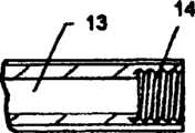
[0013]髓内钉可以具有导管,并具有临近其后端的至少一个斜槽孔。倾斜的孔在股骨颈的方向上倾斜,用于容纳滑动套筒,滑动套筒滑动穿过该倾斜的孔。此外,倾斜的孔可以具有至少两个缝,用于在插入的过程中容纳髋关节螺旋植入物叶片的边缘。在倾斜的孔之下,并与倾斜的孔相连通,髓内钉具有螺纹凹槽,用于容纳横向止动螺钉,通过螺纹机构提供了滑动套筒在髓内钉上的固定。[0013] The intramedullary nail may have a guide tube with at least one chute hole adjacent its rear end. An inclined hole is inclined in the direction of the femoral neck for receiving a sliding sleeve which slides through the inclined hole. Additionally, the angled hole may have at least two slits for accommodating the edges of the hip helical implant blades during insertion. Underneath and communicating with the inclined hole, the intramedullary nail has a threaded groove for receiving a transverse stop screw, providing fixation of the sliding sleeve on the intramedullary nail by means of a threaded mechanism.
[0014]为了获得一种允许在不损失骨组织的情况下,允许插入部分螺旋植入物的简单技术,发展了一种阶梯螺旋。此种阶梯螺旋由至少两个螺旋扭曲叶片(具有与髋关节螺旋植入物内的叶片相同的数目),上述叶片附着于其后端(远端)的底座。在插入的过程中,该阶梯螺旋牢固地固定至髋关节螺旋植入物,当两者组装在一起时,就构成了临时的完全螺旋总成。这样就允许在插入地过程中,髋关节螺旋植入物以恒定的进度和节奏进行转动,在髓内钉上缝的导向下,朝向股骨头移动,直到其到达最终位置,这样在插入的过程中,就减少了骨损失的发生。当插入完成后,仅有髋关节螺旋植入物留在股骨颈内部,由于具有一光滑轴,从而能够在滑动套筒内部向后滑动,从而允许骨裂的压缩。[0014] In order to obtain a simple technique that allows the insertion of partially helical implants without loss of bone tissue, a stepped helix was developed. This stepped helix consists of at least two helically twisted lobes (with the same number of lobes as in the hip helical implant) attached to the base of its posterior (distal) end. During insertion, the stepped helix is securely secured to the hip helical implant, and when the two are assembled together, they form a temporary full helix assembly. This allows the helical hip implant to rotate at a constant pace and rhythm during insertion, guided by the upper suture of the intramedullary nail, and move toward the femoral head until it reaches its final position. In this way, the incidence of bone loss is reduced. When insertion is complete, only the hip helical implant remains inside the femoral neck, with a smooth shaft that slides back inside the sliding sleeve, allowing compression of the fracture.
[0015]插入工具允许进行便利的进行插入。插入工具由以下部件组成:转具有转动手柄的导管轴;轴向插入件,能够插入轴的管子内;以及与轴向插入件的后端相结合的后盖。在插入前,阶梯螺旋从髋关节螺旋植入物的后面、牢固地结合于髋关节螺旋植入物,构成了螺旋总成。此后,插入工具结合至螺旋总成的后端。这样就允许具有阶梯螺旋的插入工具进行适当的结合,而髋关节螺旋植入物能够以适当的方式插入。[0015] The insertion tool allows easy insertion. The insertion tool consists of the following parts: a catheter shaft with a turning handle; an axial insert capable of being inserted into the tube of the shaft; and a rear cap combined with the rear end of the axial insert. Prior to insertion, the stepped helix is securely bonded to the hip helical implant from the rear of the hip helical implant to form the helical assembly. Thereafter, an insertion tool is coupled to the rear end of the screw assembly. This allows proper engagement of the insertion tool with the stepped helix while the hip helix implant can be inserted in a proper manner.
[0016]在插入的过程中,插入工具的后端受到阻滞,推动螺旋总成向前朝向股骨头穿过髓内钉(此前被引入髓管内)的倾斜孔。倾斜的孔处的缝引导螺旋总成的插入;与固定在髋关节螺旋植入物的阶梯螺旋一起,允许螺旋植入物以恒定的进度和节奏进行转动,如同在先前的插入过程中的那样,从而使骨损失降低至最少。[0016] During insertion, the rear end of the insertion tool is blocked, pushing the helical assembly forward toward the femoral head through the oblique hole of the intramedullary nail (previously introduced into the medullary canal). The slit at the angled hole guides the insertion of the helical assembly; together with the stepped helix secured to the hip helical implant, it allows the helical implant to rotate at a constant pace and rhythm as it did during previous insertions , thereby minimizing bone loss.
[0017]在插入完成后,阶梯螺旋和插入工具能够轻易地除去,仅留下髋关节螺旋植入物,而滑动套筒超过髋关节螺旋植入物的轴,并穿过髓内钉倾斜的孔,从而允许髋关节螺旋植入物穿过套筒向后滑动。由于上述平面地存在,就提供了转动的稳定性。此后,横向止动螺钉插入髓内钉的凹槽,将滑动套筒固定至髓内钉。[0017] After insertion is complete, the stepped helix and insertion tool can be easily removed, leaving only the hip helix implant, while the sliding sleeve passes over the axis of the hip helix implant and passes through the angled position of the intramedullary nail. hole, allowing the hip helical implant to slide back through the sleeve. Owing to the existence of the above-mentioned planar ground, rotational stability is provided. Thereafter, a lateral set screw is inserted into the groove of the nail, securing the sliding sleeve to the nail.
附图说明Description of drawings
[0018]所述的髓内接骨装置在以下的示例性附图中示出了更多的细节。通过参照以下附图,所述的髓内接骨装置可以得到更好地理解,其中同样的附图标记表示相同的部件。这些附图仅是示例性地描述了髓内接骨装置的结构、操作和使用方法,并且特定的特征既可以单独使用,也可以与其它的特征结合使用,同时本发明并不现定于所示出的实施例。[0018] The described intramedullary osteosynthesis device is shown in more detail in the following exemplary drawings. The described intramedullary osteosynthesis device can be better understood by referring to the following drawings, in which like reference numerals indicate like parts. These drawings only exemplarily describe the structure, operation and method of use of the intramedullary osteosynthesis device, and specific features can be used alone or in combination with other features, and the present invention is not limited to those shown out the example.
[0019]本发明参照以下示意性和示例性的附图阐述了更多的细节。[0019] The invention is set forth in further detail with reference to the following schematic and exemplary drawings.
[0020]附图1是在分解状态下本发明的在优选的方案中,一些部件的透视图。[0020] Accompanying drawing 1 is a perspective view of some components of the present invention in an exploded state in a preferred solution.
[0021]附图2是在分解状态下,描述于附图1中的在优选的方案中的部件的透视图。[0021] Accompanying drawing 2 is a perspective view, in an exploded state, of the components depicted in Fig. 1 in the preferred version.
[0022]附图3是髋关节螺旋植入物的透视图。[0022] Accompanying drawing 3 is a perspective view of a hip helical implant.
[0023]附图3A是描述于附图3中的髋关节螺旋植入物的前部的剖面图的局部俯视图。[0023] FIG. 3A is a partial top view of the cross-sectional view of the anterior portion of the helical hip implant depicted in FIG. 3. FIG.
[0024]附图3B是描述于附图3中的髋关节螺旋植入物的后部的剖面图的局部俯视图。[0024] FIG. 3B is a partial top view of the cross-sectional view of the posterior portion of the helical hip implant depicted in FIG. 3. FIG.
[0025]附图4A是髓内钉的透视图。[0025] Accompanying drawing 4A is a perspective view of an intramedullary nail.
[0026]附图4B是描述于附图4A中的所述髓内钉的俯视图。[0026] Accompanying drawing 4B is a top view of the intramedullary nail described in Fig. 4A.
[0027]附图4C是描述于附图4A中的所述髓内钉的斜开口的放大透视图。[0028]附图4D是描述于附图4A中的所述髓内钉沿附图4B中的4D-4-4D线的剖视图。[0027] Figure 4C is an enlarged perspective view of the oblique opening of the intramedullary nail described in Figure 4A. [0028] Accompanying
[0029]附图5是滑动套筒的透视图。[0029] Accompanying drawing 5 is a perspective view of the sliding sleeve.
[0030]附图6是横向设定螺钉的透视图。[0030] Figure 6 is a perspective view of a lateral set screw.
[0031]附图7是阶梯螺旋的透视图。[0031] Accompanying drawing 7 is a perspective view of a stepped spiral.
[0032]附图7是描述于附图7中的阶梯螺旋的底座的放大透视图。[0032] Figure 7 is an enlarged perspective view of the base of the stepped helix depicted in Figure 7.
[0033]附图8是插入工具的透视图,通过其引入轴向插入件。[0033] Figure 8 is a perspective view of an insertion tool through which an axial insert is introduced.
[0034]附图9是描述于附图8中的插入工具的盖的俯视图。[0034] FIG. 9 is a top view of the cover of the insertion tool depicted in FIG. 8. FIG.
[0035]附图9A是附图9中的插入工具的盖沿9A-9A线剖面图。[0035] Accompanying drawing 9A is a sectional view of the cover of the insertion tool in Fig. 9 along
[0036]附图9B是描述于附图8中的插入工具的盖的透视图。[0036] FIG. 9B is a perspective view of the cover of the insertion tool depicted in FIG. 8. FIG.
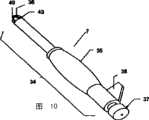
[0037]附图10是具有其全部部件的插入工具的透视图。[0037] Figure 10 is a perspective view of the insertion tool with all its components.
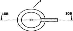
[0038]附图1OA是描述于附图10中的插入工具的仰视图。[0038] FIG. 10A is a bottom view of the insertion tool depicted in FIG. 10. FIG.
[0039]附图1OB是附图1OA中的插入工具沿IOB-IOB线的剖面图。[0039] Accompanying drawing 1OB is a sectional view of the insertion tool in the accompanying drawing 1OA along the line IOB-IOB.
[0040]附图11是具有阶梯螺旋的髋关节螺旋植入物总成的透视图。[0040] Figure 11 is a perspective view of a hip helical implant assembly with a stepped helix.
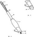
[0041]附图12是具有阶梯螺旋的所述髋关节螺旋植入物的透视图,并且插入工具不具有轴向插入件和盖。[0041] FIG. 12 is a perspective view of the hip helical implant with a stepped helix and the insertion tool without the axial insert and cap.
[0042]附图13是髋关节螺旋植入物的透视图,在引入轴向插入件后,组合了阶梯螺旋和插入工具。[0042] Figure 13 is a perspective view of a hip helical implant, after the introduction of the axial insert, combining the stepped helix and insertion tool.
[0043]附图14在其上具有盖的插入工具的后部的透视图。[0043] FIG. 14 is a perspective view of the rear of the insertion tool with a cap on it.
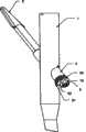
[0044]附图15是插入程序的侧视图,同时具有所述髓内钉的剖面图,显示了所述髋关节螺旋植入物通过所述髓内钉倾斜的开口。[0044] Figure 15 is a side view of the insertion procedure with a cross-sectional view of the intramedullary nail showing the hip helical implant through the angled opening of the intramedullary nail.
[0045]附图16是在插入程序的持续过程中的侧视图,同时具有所述髓内钉的剖面图,显示了所述阶梯螺旋通过所述髓内钉倾斜的开口。[0045] FIG. 16 is a side view during the continuation of the insertion procedure with a cross-sectional view of the intramedullary nail showing the stepped helix passing through the angled opening of the intramedullary nail.
[0046]附图17是除去了插入工具和阶梯螺旋的透视图。[0046] Figure 17 is a perspective view with the insertion tool and step helix removed.
[0047]附图18是在插入程序的持续的过程中,将插入工具的轴向插入件从髋关节螺旋植入物上除去的透视图。[0047] FIG. 18 is a perspective view of the axial insert of the insertion tool being removed from the hip helical implant during the continuation of the insertion procedure.
[0048]附图19是在插入程序的持续的过程中,在插入滑动套筒后的透视图。[0048] Figure 19 is a perspective view after insertion of the sliding sleeve during the continuation of the insertion procedure.
[0049]附图20在插入横向止动螺钉后,处于最终位置的透视图。[0049] Figure 20 is a perspective view of the final position after insertion of the transverse stop screw.
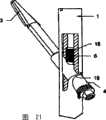
[0050]附图21是处于所述最终位置的带有局部剖面图的透视图,并且具有具有可供选择的共轴止动螺钉。[0050] Figure 21 is a perspective view with a partial cutaway view in the final position and with an optional coaxial set screw.
具体实施方式Detailed ways
[0051]附图1和2描述了髓内接骨装置优选实施例的独立部件,包括具有任选的远端锁紧螺钉2的髓内钉1,髋关节螺旋植入物3,滑动套筒4,横向止动螺钉5和任选的共轴的止动螺钉6;以及插入工具7和阶梯螺旋8。在插入程序的持续的过程中可以应用插入工具和阶梯螺旋8。Figures 1 and 2 depict the individual components of a preferred embodiment of an intramedullary osteosynthesis device, including an
[0052]附图3至3B描述了髋关节螺旋植入物3的优选方案,由前螺旋部分11和后光滑轴9组成,附属于前螺旋部分11的轴线的是截顶圆锥形状。可以预期的是具有额外的叶片。各叶片的后端具有孔12,用于容纳位于阶梯螺旋8的阶梯叶片28的前端的楔子30(附图7),这是为了允许在螺旋植入物3的叶片10与阶梯叶片28之间进行牢固的固定。在插入持续的过程中,螺旋植入物的轴9是中空的,从而能够容纳基尔希纳氏钢丝(Kirschner wire);管子13具有设置有内螺纹的后部14,用于容纳插入工具7的轴向插入件36。髋关节螺旋植入物3的轴9具有外平面15,邻接于位于滑动套筒4内的内平面23用于阻止转动,尽管可以允许髋关节螺旋植入物3在滑动套筒4的内部进行滑动。此外,在轴9的后端,轴9可以具有用于容纳位于阶梯螺旋的上的前部楔片31,从而改进阶梯螺旋8在髋关节螺旋植入物3上的固定。[0052] Accompanying
[0053]髓内钉1(附图4A至4D)具有中空的管子17。管子17具有用于容纳任选的共轴止动螺钉6的螺纹部分18。至少具有一个与管子17相连通的斜槽孔19,用于容纳滑动套筒4。倾斜的孔19具有至少两个缝20和42,用于容纳髋关节螺旋植入物3的叶片10的边缘,为其插入进行导向。在低于倾斜的孔19(远端更低)以及与其进行连通的位置,髓内钉1具有螺纹切口21,用于横向止动螺钉5(附图4C和4D)。倾斜的孔19具有缝20、42和螺纹切口21,倾斜的孔19是倾斜的,使得当髓内钉定位于股骨髓管的内部时,所述缝和切口的轴线朝向股骨颈的轴线(附图4D)。此外,髓内钉1具有远端的横向孔22,用于容纳任选的远端锁紧螺钉2。[0053] The intramedullary nail 1 (FIGS. 4A to 4D) has a
[0054]显示于附图5中的滑动套筒4设置有一管,该管具有用于邻接髋关节螺旋植入物3的轴9的外平面15的内平面23。在套筒4的后端,套筒4可以具有外部的棱25,用于与横向止动螺钉5进行啮合,从而将滑动套筒4固定至髓内钉1上。滑动套筒4以滑动的方式穿过髓内钉1倾斜的孔19,并由横向止动螺钉5固定至其上。[0054] The sliding sleeve 4 shown in FIG. 5 is provided with a tube having an
[0055]横向止动螺钉5描述于附图6中,还可以具有外螺纹26,用于与滑动套筒4的后部螺纹部分25相啮合。横向止动螺钉5在其后部的边缘还具有六边形的孔27,用于容纳六边形的螺丝起子。孔27采用其它的构型也是可以预期的。[0055] The
[0056]选择性的是,任选的共轴的止动螺钉6(显示于附图2)可以用于完成将将滑动套筒4固定至髓内钉1。共轴的止动螺钉6可以插入髓内钉螺纹管子18的内部,用于密封髓内钉1倾斜的孔19内部的滑动套筒4。[0056] Optionally, an optional coaxial set screw 6 (shown in FIG. 2 ) may be used to complete the fixation of the sliding sleeve 4 to the
[0057]附图7和7A描述了阶梯螺旋8的优选方案,阶梯螺旋8包括至少两个(与髋关节螺旋植入物3的叶片的数目相同)螺旋的扭曲阶梯叶片28,并且其后端固定于带有槽的底座29。阶梯叶片28通过楔子30与髋关节螺旋植入物3的叶片的后端相结合,楔子30位于阶梯叶片28的前缘,并且适配于髋关节螺旋植入物3的叶片10的后缘上的孔12。阶梯螺旋8的底座29在其最前面可以具有前部楔片31,并且适配于位于髋关节螺旋植入物3的轴9的后端的后部凹槽16。此外,底座29具有显示于附图7A中的横向缝32,可以容纳插入工具7。此外,底座29还可以具有导管33,从而允许插入工具7的轴向插入件36穿过导管33,以与髋关节螺旋植入物3的后部相结合。Accompanying drawing 7 and 7A has described the preferred scheme of
[0058]插入工具7描述于附图8至10B中,插入工具7包括具有转动手柄35的导管轴34,轴向插入件36和后盖37。转动手柄35的装配超过了轴34,从而允许手柄35围绕轴34的纵轴转动。导管轴34在其前端具有缝43,用于在阶梯螺旋8的底座29处与横向缝32相结合。轴34的后部具有凸出部分38,用于在插入完成之后移出插入工具7时阻止向后移动。此外,轴34可以是导管39(如附图8和10B所示),用于容纳轴向插入件36。显示于附图10和1OB中的轴向插入件36是一管子,具有比插入工具34的轴的直径更小的直径,使得能够以滑动方式穿过轴34的导管39。轴向插入件36还可以具有设有外螺纹的前端40,用于与内螺纹14相啮合,从而在插入程序持续的过程中在髋关节螺旋植入物3的轴9处进行彼此之间牢固的结合。此外,轴向插入件36可以具有设置外螺纹的后端41,用于与插入工具7的后盖37的内螺纹孔44相啮合(描述于附图9至9B中),从而改善了插入工具7与螺旋植入物3之间的牢固性。[0058] The
[0059]在插入之前,插入工具7与阶梯螺旋8、髋关节螺旋植入物3装配在一起。装配程序描述于附图11至14中。在第一步中,阶梯螺旋8牢固地装配至髋关节螺旋植入物3的后部,构成了临时性的完整螺旋,正如附图11中描述地那样。此后,插入工具7的轴34经由槽机构32、43结合至阶梯螺旋8的底座29,如附图12所示。插入工具7的轴向插入件通过插入工具7的轴34导管39引入,如附图13所示。轴向插入件36的前部螺纹端4040穿过阶梯螺旋8的底座29的导管33,并进入髋关节螺旋植入物3轴9内的内部螺纹孔14。此后,轴向插入件36在髋关节螺旋植入物3内旋转。装配程序的最终步骤描述于附图14中,在那里插入工具7盖37通过盖37的内螺纹孔44结合至轴向插入件36的后螺纹端41。这样就允许在插入程序的持续过程中,插入工具7与阶梯螺旋8、髋关节螺旋植入物3之间具有适当的接合。[0059] Before insertion, the
[0060]附图15-21描述髓内接骨装置的插入程序。在第一步中,髓内钉1引入股骨髓管的内部,这种方式与通常的技术是一样的。然后,髋关节螺旋植入物3通过髓内钉1的倾斜的孔19引入,使得髋关节螺旋植入物3的叶片10穿过髓内钉1的缝20和42,并且引导髋关节螺旋植入物3的插入,如附图15中描述的那样。此后,阶梯螺旋的阶梯叶片28经由髓内钉上的相同的缝穿过,并且相对于髋关节螺旋植入物3具有相同的方向,如附图16所示,直到髋关节螺旋植入物3到达股骨头内部的最终位置。这样就允许在插入的过程中,髋关节螺旋植入物3以恒定的进度和节奏进行转动,这是因为其首先朝向股骨头,直到到达最终位置时为止,由髓内钉1的缝20、42进行导向。在插入的过程中,有必要阻止插入工具的后端(近端),促使螺旋总成朝向股骨头穿过髓内钉1倾斜的孔19。在插入的过程中,插入工具7的转动手柄35使得能够握持插入工具7,而不需要随着插入工具7的轴34的转动,以及随后的在插入过程中髋关节螺旋植入物3的转动,而转动其手腕,如附图16所示。[0060] Figures 15-21 depict the insertion procedure for an intramedullary bone-synthesis device. In a first step, the
[0061]在插入完成后,阶梯螺旋8和插入工具7均除去。这一过程描述于附图17和18中。在第一步中,插入工具7的后盖37除去;此后,插入工具7的轴的凸出部分阻止向后的移动,引起插入工具7的轴34和阶梯螺旋8结合在一起,向后滑过插入工具的轴向插入件36,如附图17所示,仅将轴向插入件36固定在髋关节螺旋植入物3上。在最后的步骤中,描述于附图18中,轴向插入件36从髋关节螺旋植入物3上旋松,仅留下髋关节螺旋植入物3位于股骨颈的内部,而髋关节螺旋植入物3的轴9穿过髓内钉1的倾斜的孔19。[0061] After the insertion is complete, both the
[0062]此后,滑动套筒4推过髋关节螺旋植入物3的轴9,使得滑动套筒4的内平面邻接髋关节螺旋植入物3的平面15,并且朝向股骨颈穿过髓内钉1倾斜的孔19,如附图19中描述的那样。这样就允许髋关节螺旋植入物3穿过滑动套筒4向后滑动,同时保持转动稳定性。为了将滑动套筒4固定至髓内钉1,横向止动螺钉5在位于髓内钉1内的倾斜的螺纹凹槽21处引入,并与滑动套筒4的外螺纹端25相啮合,使其固定至髓内钉1,如附图20所示。将滑动套筒4固定至髓内钉1的另一个机构是共轴的止动螺钉6,该共轴的止动螺钉位于髓内钉1的带有棱的管子18的内部,并且向下设置朝向滑动套筒4,以便在倾斜的孔19的内部向上紧固滑动套筒4,如附图21中所示。[0062] Thereafter, the sliding sleeve 4 is pushed through the shaft 9 of the hip
[0063]尽管本发明及其优点已经进行了详细说明,但是应当理解,在不脱离如附加的权利要求所限定的精神和范围的情况下,还是存在各种的变化、置换和替代。此外,本发明的应用范围不现定于在说明书中所描述的工艺、设备、产品、物质成分、装置、方法和步骤的特定实施例。正如本领域的普通技术人员从本发明公开的内容可以轻易获知的那样,各种工艺、设备、产品、物质成分、装置、方法、步骤、现有的或者随后发展的那些,只要是相应于在此描述的实施例且具有基本上相同的功能或者能够获得基本上相同的结果,根据本发明均可以进行应用。[0063] Although the present invention and its advantages have been described in detail, it should be understood that various changes, substitutions and substitutions can be made therein without departing from the spirit and scope as defined by the appended claims. Furthermore, the scope of application of the present invention is not limited to the specific embodiments of the process, apparatus, product, composition of matter, means, methods and steps described in the specification. As those of ordinary skill in the art can easily understand from the disclosure of the present invention, various processes, equipment, products, material components, devices, methods, steps, existing or subsequently developed, as long as they correspond to the Embodiments described herein that perform substantially the same function or achieve substantially the same results can be used in accordance with the present invention.
Claims (15)
Applications Claiming Priority (3)
| Application Number | Priority Date | Filing Date | Title |
|---|---|---|---|
| US79362206P | 2006-04-21 | 2006-04-21 | |
| US60/793,622 | 2006-04-21 | ||
| PCT/US2007/009739WO2007124099A2 (en) | 2006-04-21 | 2007-04-20 | Hip helical implant |
Publications (2)
| Publication Number | Publication Date |
|---|---|
| CN101426442Atrue CN101426442A (en) | 2009-05-06 |
| CN101426442B CN101426442B (en) | 2013-05-29 |
Family
ID=38442097
Family Applications (1)
| Application Number | Title | Priority Date | Filing Date |
|---|---|---|---|
| CN2007800143361AExpired - Fee RelatedCN101426442B (en) | 2006-04-21 | 2007-04-20 | hip helical implant |
Country Status (15)
| Country | Link |
|---|---|
| US (1) | US8353910B2 (en) |
| EP (1) | EP2018127B1 (en) |
| JP (1) | JP5254210B2 (en) |
| KR (1) | KR101409468B1 (en) |
| CN (1) | CN101426442B (en) |
| AT (1) | ATE468077T1 (en) |
| AU (1) | AU2007240665A1 (en) |
| BR (1) | BRPI0710640A2 (en) |
| CA (1) | CA2649444C (en) |
| CO (1) | CO6140009A2 (en) |
| DE (1) | DE602007006657D1 (en) |
| ES (1) | ES2343283T3 (en) |
| PL (1) | PL2018127T3 (en) |
| WO (1) | WO2007124099A2 (en) |
| ZA (1) | ZA200808535B (en) |
Cited By (5)
| Publication number | Priority date | Publication date | Assignee | Title |
|---|---|---|---|---|
| CN103327918A (en)* | 2011-01-21 | 2013-09-25 | 新特斯有限责任公司 | Trochanteric femoral nail augmentable |
| CN104688312A (en)* | 2015-03-17 | 2015-06-10 | 苏州瑞华医院有限公司 | Locking plate type intramedullary nail for femoral intertrochanteric fracture treatment |
| CN109758271A (en)* | 2019-02-20 | 2019-05-17 | 江苏百易得医疗科技有限公司 | A kind of fusion device |
| CN111281512A (en)* | 2020-02-27 | 2020-06-16 | 天津市威曼生物材料有限公司 | Assembled proximal femur compression screw group |
| CN113229915A (en)* | 2021-04-21 | 2021-08-10 | 天津市金兴达实业有限公司 | Intramedullary pin |
Families Citing this family (23)
| Publication number | Priority date | Publication date | Assignee | Title |
|---|---|---|---|---|
| WO2008064059A2 (en)* | 2006-11-17 | 2008-05-29 | Synthes(U.S.A.) | Sliding hip helical implant |
| US9044282B2 (en) | 2008-06-24 | 2015-06-02 | Extremity Medical Llc | Intraosseous intramedullary fixation assembly and method of use |
| CN102413779B (en)* | 2009-05-05 | 2014-03-12 | 斯恩蒂斯有限公司 | nail locking system |
| WO2011044917A1 (en)* | 2009-10-13 | 2011-04-21 | Zimmer Gmbh | An orthopedic nail and an orthopedic nail system |
| US10588647B2 (en) | 2010-03-01 | 2020-03-17 | Stryker European Holdings I, Llc | Computer assisted surgery system |
| EP2586393B1 (en)* | 2011-10-28 | 2014-10-08 | Stryker Trauma GmbH | Locking hole arrangement |
| US10039606B2 (en) | 2012-09-27 | 2018-08-07 | Stryker European Holdings I, Llc | Rotational position determination |
| EP3060146B1 (en)* | 2013-10-22 | 2018-10-03 | General Surgical Company (India) Pvt. Limited | A device for bone support with improved rotational stability |
| US10045803B2 (en) | 2014-07-03 | 2018-08-14 | Mayo Foundation For Medical Education And Research | Sacroiliac joint fusion screw and method |
| US20160081725A1 (en)* | 2014-08-12 | 2016-03-24 | Vilex In Tennessee, Inc. | Intramedullary Nail |
| EP3273889B1 (en) | 2015-03-25 | 2020-12-02 | Pier Giovanni Menci | Intramedullary nail for the treatment of fractures of long bones |
| EP3150154B1 (en)* | 2015-09-29 | 2019-10-30 | Orthofix S.r.l. | Endosseous screw assembly and internal fixation system comprising said endosseous screw assembly |
| US9833321B2 (en) | 2016-04-25 | 2017-12-05 | Imds Llc | Joint fusion instrumentation and methods |
| US10413332B2 (en) | 2016-04-25 | 2019-09-17 | Imds Llc | Joint fusion implant and methods |
| US11045242B2 (en) | 2016-09-22 | 2021-06-29 | Globus Medical, Inc. | Systems and methods for intramedullary nail implantation |
| US10751096B2 (en) | 2016-09-22 | 2020-08-25 | Bala Sundararajan | Systems and methods for intramedullary nail implantation |
| US10299847B2 (en) | 2016-09-22 | 2019-05-28 | Globus Medical, Inc. | Systems and methods for intramedullary nail implantation |
| US11083503B2 (en) | 2016-09-22 | 2021-08-10 | Globus Medical, Inc. | Systems and methods for intramedullary nail implantation |
| EP3391841A1 (en) | 2017-04-20 | 2018-10-24 | Stöckli Group AG | Longitudinal bone implant |
| US11446072B2 (en) | 2017-10-10 | 2022-09-20 | DePuy Synthes Products, Inc. | Self-retaining nail to insertion handle interface |
| WO2020214726A1 (en)* | 2019-04-17 | 2020-10-22 | University Of Pittsburgh - Of The Commonwealth System Of Higher Education | Hip joint tether device |
| KR102576602B1 (en)* | 2020-07-09 | 2023-09-11 | 주식회사 제일메디칼코퍼레이션 | Rotation prevention member of leg screw for fixing bone |
| US12004785B2 (en) | 2022-04-21 | 2024-06-11 | DePuy Synthes Products, Inc. | Retrograde femoral intramedullary nail, and related systems and methods |
Citations (6)
| Publication number | Priority date | Publication date | Assignee | Title |
|---|---|---|---|---|
| US5300074A (en)* | 1990-12-17 | 1994-04-05 | Synthes (U.S.A.) | Two-part angle plate |
| US5810821A (en)* | 1997-03-28 | 1998-09-22 | Biomet Inc. | Bone fixation screw system |
| US6443954B1 (en)* | 2001-04-24 | 2002-09-03 | Dale G. Bramlet | Femoral nail intramedullary system |
| US20020133156A1 (en)* | 1999-06-10 | 2002-09-19 | Cole J. Dean | Femoral intramedullary rod system |
| US20050055024A1 (en)* | 2003-09-08 | 2005-03-10 | James Anthony H. | Orthopaedic implant and screw assembly |
| CN1694650A (en)* | 2002-10-29 | 2005-11-09 | 马斯医药技术股份公司 | Device for the treatment of fractures of the femur |
Family Cites Families (7)
| Publication number | Priority date | Publication date | Assignee | Title |
|---|---|---|---|---|
| GB9113578D0 (en)* | 1991-06-24 | 1991-08-14 | Howmedica | Intramedullary intertrochanteric fracture fixation appliance |
| US5741256A (en)* | 1997-01-13 | 1998-04-21 | Synthes (U.S.A.) | Helical osteosynthetic implant |
| DE29804268U1 (en)* | 1998-03-11 | 1998-05-14 | Synthes AG Chur, Chur, Graubünden | Spiral blade insertion instrument |
| TR200402686T4 (en)* | 2000-12-08 | 2004-11-22 | Synthes Ag Chur | Means for fixing the bones, in particular the spine parts, relative to each other |
| US7247171B2 (en)* | 2002-03-11 | 2007-07-24 | Sotereanos Nicholas G | Modular hip implants |
| US7632275B2 (en)* | 2004-07-01 | 2009-12-15 | Howmedica Osteonics Corp. | Orthopedic reamer |
| US7488328B2 (en)* | 2004-07-20 | 2009-02-10 | Yechiel Gotfried | Targeting apparatus for bone fixation device |
- 2007
- 2007-04-20WOPCT/US2007/009739patent/WO2007124099A2/enactiveApplication Filing
- 2007-04-20PLPL07755851Tpatent/PL2018127T3/enunknown
- 2007-04-20DEDE602007006657Tpatent/DE602007006657D1/enactiveActive
- 2007-04-20KRKR1020087024529Apatent/KR101409468B1/ennot_activeExpired - Fee Related
- 2007-04-20ZAZA200808535Apatent/ZA200808535B/enunknown
- 2007-04-20CNCN2007800143361Apatent/CN101426442B/ennot_activeExpired - Fee Related
- 2007-04-20ESES07755851Tpatent/ES2343283T3/enactiveActive
- 2007-04-20CACA2649444Apatent/CA2649444C/ennot_activeExpired - Fee Related
- 2007-04-20AUAU2007240665Apatent/AU2007240665A1/ennot_activeAbandoned
- 2007-04-20BRBRPI0710640-8Apatent/BRPI0710640A2/ennot_activeApplication Discontinuation
- 2007-04-20USUS12/294,567patent/US8353910B2/ennot_activeExpired - Fee Related
- 2007-04-20JPJP2009506617Apatent/JP5254210B2/ennot_activeExpired - Fee Related
- 2007-04-20ATAT07755851Tpatent/ATE468077T1/enactive
- 2007-04-20EPEP07755851Apatent/EP2018127B1/ennot_activeNot-in-force
- 2008
- 2008-10-20COCO08111500Apatent/CO6140009A2/enunknown
Patent Citations (6)
| Publication number | Priority date | Publication date | Assignee | Title |
|---|---|---|---|---|
| US5300074A (en)* | 1990-12-17 | 1994-04-05 | Synthes (U.S.A.) | Two-part angle plate |
| US5810821A (en)* | 1997-03-28 | 1998-09-22 | Biomet Inc. | Bone fixation screw system |
| US20020133156A1 (en)* | 1999-06-10 | 2002-09-19 | Cole J. Dean | Femoral intramedullary rod system |
| US6443954B1 (en)* | 2001-04-24 | 2002-09-03 | Dale G. Bramlet | Femoral nail intramedullary system |
| CN1694650A (en)* | 2002-10-29 | 2005-11-09 | 马斯医药技术股份公司 | Device for the treatment of fractures of the femur |
| US20050055024A1 (en)* | 2003-09-08 | 2005-03-10 | James Anthony H. | Orthopaedic implant and screw assembly |
Cited By (6)
| Publication number | Priority date | Publication date | Assignee | Title |
|---|---|---|---|---|
| CN103327918A (en)* | 2011-01-21 | 2013-09-25 | 新特斯有限责任公司 | Trochanteric femoral nail augmentable |
| CN104688312A (en)* | 2015-03-17 | 2015-06-10 | 苏州瑞华医院有限公司 | Locking plate type intramedullary nail for femoral intertrochanteric fracture treatment |
| CN109758271A (en)* | 2019-02-20 | 2019-05-17 | 江苏百易得医疗科技有限公司 | A kind of fusion device |
| CN109758271B (en)* | 2019-02-20 | 2024-05-14 | 江苏百易得医疗科技有限公司 | Fusion device |
| CN111281512A (en)* | 2020-02-27 | 2020-06-16 | 天津市威曼生物材料有限公司 | Assembled proximal femur compression screw group |
| CN113229915A (en)* | 2021-04-21 | 2021-08-10 | 天津市金兴达实业有限公司 | Intramedullary pin |
Also Published As
| Publication number | Publication date |
|---|---|
| CN101426442B (en) | 2013-05-29 |
| ES2343283T3 (en) | 2010-07-27 |
| CA2649444C (en) | 2014-08-05 |
| EP2018127A2 (en) | 2009-01-28 |
| WO2007124099A2 (en) | 2007-11-01 |
| DE602007006657D1 (en) | 2010-07-01 |
| CA2649444A1 (en) | 2007-11-01 |
| BRPI0710640A2 (en) | 2011-08-23 |
| US8353910B2 (en) | 2013-01-15 |
| KR101409468B1 (en) | 2014-06-18 |
| JP5254210B2 (en) | 2013-08-07 |
| CO6140009A2 (en) | 2010-03-19 |
| KR20090008210A (en) | 2009-01-21 |
| AU2007240665A1 (en) | 2007-11-01 |
| ATE468077T1 (en) | 2010-06-15 |
| EP2018127B1 (en) | 2010-05-19 |
| US20100063503A1 (en) | 2010-03-11 |
| ZA200808535B (en) | 2009-12-30 |
| WO2007124099A3 (en) | 2008-03-06 |
| JP2009534106A (en) | 2009-09-24 |
| PL2018127T3 (en) | 2010-10-29 |
Similar Documents
| Publication | Publication Date | Title |
|---|---|---|
| CN101426442B (en) | hip helical implant | |
| US12414805B2 (en) | Implantable compression screws | |
| JP7573351B2 (en) | Systems and methods for intramedullary nail implantation | |
| US10258380B2 (en) | Bone compression and fixation devices | |
| US6706046B2 (en) | Intramedullary fixation device for metaphyseal long bone fractures and methods of using the same | |
| US9192416B2 (en) | Intramedullary rod with spiraling flutes | |
| AU2008204818B2 (en) | Percutaneous intramedullary bone repair device | |
| EP1713410B1 (en) | Proximal humeral fracture fixation system comprising a plate including a post rotationally locked in a post hole, and a rigid cross support | |
| JP4823917B2 (en) | Humeral nail with insert for fixing screw | |
| US8211107B2 (en) | Modular, blade-rod, intramedullary fixation device | |
| US20150250503A1 (en) | Lagwire system and method for the fixation of bone fractures | |
| US20110034925A1 (en) | Lagwire system and method for the fixation of bone fractures | |
| US11020159B2 (en) | Differential compression bone screw | |
| AU2005316909A1 (en) | Bone plate with pre-assembled drill guide tips | |
| JP2013544129A (en) | Bone implant | |
| EP1833392A1 (en) | Trocar with obturator having longitudinally passing holes for guide wires | |
| JP2025003736A (en) | Intramedullary nail and method of using same | |
| WO2008064059A2 (en) | Sliding hip helical implant | |
| WO2008097795A1 (en) | Sliding hip helical implant | |
| KR101200899B1 (en) | Intramedullary rod with spiraling flutes |
Legal Events
| Date | Code | Title | Description |
|---|---|---|---|
| C06 | Publication | ||
| PB01 | Publication | ||
| C10 | Entry into substantive examination | ||
| SE01 | Entry into force of request for substantive examination | ||
| C14 | Grant of patent or utility model | ||
| GR01 | Patent grant | ||
| CF01 | Termination of patent right due to non-payment of annual fee | Granted publication date:20130529 Termination date:20160420 | |
| CF01 | Termination of patent right due to non-payment of annual fee |