CN101425672A - System and method for control of power distribution networks - Google Patents
System and method for control of power distribution networksDownload PDFInfo
- Publication number
- CN101425672A CN101425672ACNA2008101731210ACN200810173121ACN101425672ACN 101425672 ACN101425672 ACN 101425672ACN A2008101731210 ACNA2008101731210 ACN A2008101731210ACN 200810173121 ACN200810173121 ACN 200810173121ACN 101425672 ACN101425672 ACN 101425672A
- Authority
- CN
- China
- Prior art keywords
- controller
- network
- node
- power
- data
- Prior art date
- Legal status (The legal status is an assumption and is not a legal conclusion. Google has not performed a legal analysis and makes no representation as to the accuracy of the status listed.)
- Granted
Links
Images


Classifications
- H—ELECTRICITY
- H02—GENERATION; CONVERSION OR DISTRIBUTION OF ELECTRIC POWER
- H02H—EMERGENCY PROTECTIVE CIRCUIT ARRANGEMENTS
- H02H7/00—Emergency protective circuit arrangements specially adapted for specific types of electric machines or apparatus or for sectionalised protection of cable or line systems, and effecting automatic switching in the event of an undesired change from normal working conditions
- H02H7/26—Sectionalised protection of cable or line systems, e.g. for disconnecting a section on which a short-circuit, earth fault, or arc discharge has occured
- H02H7/261—Sectionalised protection of cable or line systems, e.g. for disconnecting a section on which a short-circuit, earth fault, or arc discharge has occured involving signal transmission between at least two stations
- G—PHYSICS
- G06—COMPUTING OR CALCULATING; COUNTING
- G06Q—INFORMATION AND COMMUNICATION TECHNOLOGY [ICT] SPECIALLY ADAPTED FOR ADMINISTRATIVE, COMMERCIAL, FINANCIAL, MANAGERIAL OR SUPERVISORY PURPOSES; SYSTEMS OR METHODS SPECIALLY ADAPTED FOR ADMINISTRATIVE, COMMERCIAL, FINANCIAL, MANAGERIAL OR SUPERVISORY PURPOSES, NOT OTHERWISE PROVIDED FOR
- G06Q10/00—Administration; Management
- G06Q10/06—Resources, workflows, human or project management; Enterprise or organisation planning; Enterprise or organisation modelling
- G—PHYSICS
- G06—COMPUTING OR CALCULATING; COUNTING
- G06Q—INFORMATION AND COMMUNICATION TECHNOLOGY [ICT] SPECIALLY ADAPTED FOR ADMINISTRATIVE, COMMERCIAL, FINANCIAL, MANAGERIAL OR SUPERVISORY PURPOSES; SYSTEMS OR METHODS SPECIALLY ADAPTED FOR ADMINISTRATIVE, COMMERCIAL, FINANCIAL, MANAGERIAL OR SUPERVISORY PURPOSES, NOT OTHERWISE PROVIDED FOR
- G06Q50/00—Information and communication technology [ICT] specially adapted for implementation of business processes of specific business sectors, e.g. utilities or tourism
- G06Q50/06—Energy or water supply
- H—ELECTRICITY
- H02—GENERATION; CONVERSION OR DISTRIBUTION OF ELECTRIC POWER
- H02H—EMERGENCY PROTECTIVE CIRCUIT ARRANGEMENTS
- H02H1/00—Details of emergency protective circuit arrangements
- H02H1/0092—Details of emergency protective circuit arrangements concerning the data processing means, e.g. expert systems, neural networks
- H—ELECTRICITY
- H02—GENERATION; CONVERSION OR DISTRIBUTION OF ELECTRIC POWER
- H02H—EMERGENCY PROTECTIVE CIRCUIT ARRANGEMENTS
- H02H3/00—Emergency protective circuit arrangements for automatic disconnection directly responsive to an undesired change from normal electric working condition with or without subsequent reconnection ; integrated protection
- H02H3/02—Details
- H02H3/06—Details with automatic reconnection
- H02H3/063—Details concerning the co-operation of many similar arrangements, e.g. in a network
- H—ELECTRICITY
- H02—GENERATION; CONVERSION OR DISTRIBUTION OF ELECTRIC POWER
- H02H—EMERGENCY PROTECTIVE CIRCUIT ARRANGEMENTS
- H02H7/00—Emergency protective circuit arrangements specially adapted for specific types of electric machines or apparatus or for sectionalised protection of cable or line systems, and effecting automatic switching in the event of an undesired change from normal working conditions
- H02H7/26—Sectionalised protection of cable or line systems, e.g. for disconnecting a section on which a short-circuit, earth fault, or arc discharge has occured
- H02H7/261—Sectionalised protection of cable or line systems, e.g. for disconnecting a section on which a short-circuit, earth fault, or arc discharge has occured involving signal transmission between at least two stations
- H02H7/262—Sectionalised protection of cable or line systems, e.g. for disconnecting a section on which a short-circuit, earth fault, or arc discharge has occured involving signal transmission between at least two stations involving transmissions of switching or blocking orders
- H—ELECTRICITY
- H02—GENERATION; CONVERSION OR DISTRIBUTION OF ELECTRIC POWER
- H02H—EMERGENCY PROTECTIVE CIRCUIT ARRANGEMENTS
- H02H7/00—Emergency protective circuit arrangements specially adapted for specific types of electric machines or apparatus or for sectionalised protection of cable or line systems, and effecting automatic switching in the event of an undesired change from normal working conditions
- H02H7/26—Sectionalised protection of cable or line systems, e.g. for disconnecting a section on which a short-circuit, earth fault, or arc discharge has occured
- H02H7/261—Sectionalised protection of cable or line systems, e.g. for disconnecting a section on which a short-circuit, earth fault, or arc discharge has occured involving signal transmission between at least two stations
- H02H7/263—Sectionalised protection of cable or line systems, e.g. for disconnecting a section on which a short-circuit, earth fault, or arc discharge has occured involving signal transmission between at least two stations involving transmissions of measured values
- H—ELECTRICITY
- H02—GENERATION; CONVERSION OR DISTRIBUTION OF ELECTRIC POWER
- H02H—EMERGENCY PROTECTIVE CIRCUIT ARRANGEMENTS
- H02H7/00—Emergency protective circuit arrangements specially adapted for specific types of electric machines or apparatus or for sectionalised protection of cable or line systems, and effecting automatic switching in the event of an undesired change from normal working conditions
- H02H7/26—Sectionalised protection of cable or line systems, e.g. for disconnecting a section on which a short-circuit, earth fault, or arc discharge has occured
- H02H7/28—Sectionalised protection of cable or line systems, e.g. for disconnecting a section on which a short-circuit, earth fault, or arc discharge has occured for meshed systems
- H—ELECTRICITY
- H02—GENERATION; CONVERSION OR DISTRIBUTION OF ELECTRIC POWER
- H02J—CIRCUIT ARRANGEMENTS OR SYSTEMS FOR SUPPLYING OR DISTRIBUTING ELECTRIC POWER; SYSTEMS FOR STORING ELECTRIC ENERGY
- H02J1/00—Circuit arrangements for DC mains or DC distribution networks
- H—ELECTRICITY
- H02—GENERATION; CONVERSION OR DISTRIBUTION OF ELECTRIC POWER
- H02J—CIRCUIT ARRANGEMENTS OR SYSTEMS FOR SUPPLYING OR DISTRIBUTING ELECTRIC POWER; SYSTEMS FOR STORING ELECTRIC ENERGY
- H02J13/00—Circuit arrangements for providing remote indication of network conditions, e.g. an instantaneous record of the open or closed condition of each circuitbreaker in the network; Circuit arrangements for providing remote control of switching means in a power distribution network, e.g. switching in and out of current consumers by using a pulse code signal carried by the network
- H02J13/00006—Circuit arrangements for providing remote indication of network conditions, e.g. an instantaneous record of the open or closed condition of each circuitbreaker in the network; Circuit arrangements for providing remote control of switching means in a power distribution network, e.g. switching in and out of current consumers by using a pulse code signal carried by the network characterised by information or instructions transport means between the monitoring, controlling or managing units and monitored, controlled or operated power network element or electrical equipment
- H02J13/00016—Circuit arrangements for providing remote indication of network conditions, e.g. an instantaneous record of the open or closed condition of each circuitbreaker in the network; Circuit arrangements for providing remote control of switching means in a power distribution network, e.g. switching in and out of current consumers by using a pulse code signal carried by the network characterised by information or instructions transport means between the monitoring, controlling or managing units and monitored, controlled or operated power network element or electrical equipment using a wired telecommunication network or a data transmission bus
- H—ELECTRICITY
- H02—GENERATION; CONVERSION OR DISTRIBUTION OF ELECTRIC POWER
- H02J—CIRCUIT ARRANGEMENTS OR SYSTEMS FOR SUPPLYING OR DISTRIBUTING ELECTRIC POWER; SYSTEMS FOR STORING ELECTRIC ENERGY
- H02J13/00—Circuit arrangements for providing remote indication of network conditions, e.g. an instantaneous record of the open or closed condition of each circuitbreaker in the network; Circuit arrangements for providing remote control of switching means in a power distribution network, e.g. switching in and out of current consumers by using a pulse code signal carried by the network
- H02J13/00032—Systems characterised by the controlled or operated power network elements or equipment, the power network elements or equipment not otherwise provided for
- H02J13/00034—Systems characterised by the controlled or operated power network elements or equipment, the power network elements or equipment not otherwise provided for the elements or equipment being or involving an electric power substation
- H—ELECTRICITY
- H02—GENERATION; CONVERSION OR DISTRIBUTION OF ELECTRIC POWER
- H02J—CIRCUIT ARRANGEMENTS OR SYSTEMS FOR SUPPLYING OR DISTRIBUTING ELECTRIC POWER; SYSTEMS FOR STORING ELECTRIC ENERGY
- H02J13/00—Circuit arrangements for providing remote indication of network conditions, e.g. an instantaneous record of the open or closed condition of each circuitbreaker in the network; Circuit arrangements for providing remote control of switching means in a power distribution network, e.g. switching in and out of current consumers by using a pulse code signal carried by the network
- H02J13/00032—Systems characterised by the controlled or operated power network elements or equipment, the power network elements or equipment not otherwise provided for
- H02J13/00036—Systems characterised by the controlled or operated power network elements or equipment, the power network elements or equipment not otherwise provided for the elements or equipment being or involving switches, relays or circuit breakers
- H02J13/0004—Systems characterised by the controlled or operated power network elements or equipment, the power network elements or equipment not otherwise provided for the elements or equipment being or involving switches, relays or circuit breakers involved in a protection system
- H—ELECTRICITY
- H02—GENERATION; CONVERSION OR DISTRIBUTION OF ELECTRIC POWER
- H02J—CIRCUIT ARRANGEMENTS OR SYSTEMS FOR SUPPLYING OR DISTRIBUTING ELECTRIC POWER; SYSTEMS FOR STORING ELECTRIC ENERGY
- H02J3/00—Circuit arrangements for AC mains or AC distribution networks
- H—ELECTRICITY
- H02—GENERATION; CONVERSION OR DISTRIBUTION OF ELECTRIC POWER
- H02J—CIRCUIT ARRANGEMENTS OR SYSTEMS FOR SUPPLYING OR DISTRIBUTING ELECTRIC POWER; SYSTEMS FOR STORING ELECTRIC ENERGY
- H02J3/00—Circuit arrangements for AC mains or AC distribution networks
- H02J3/007—Arrangements for selectively connecting the load or loads to one or several among a plurality of power lines or power sources
- H02J3/0073—Arrangements for selectively connecting the load or loads to one or several among a plurality of power lines or power sources for providing alternative feeding paths between load and source when the main path fails, e.g. transformers, busbars
- H—ELECTRICITY
- H02—GENERATION; CONVERSION OR DISTRIBUTION OF ELECTRIC POWER
- H02J—CIRCUIT ARRANGEMENTS OR SYSTEMS FOR SUPPLYING OR DISTRIBUTING ELECTRIC POWER; SYSTEMS FOR STORING ELECTRIC ENERGY
- H02J3/00—Circuit arrangements for AC mains or AC distribution networks
- H02J3/38—Arrangements for parallely feeding a single network by two or more generators, converters or transformers
- H02J3/381—Dispersed generators
- H—ELECTRICITY
- H02—GENERATION; CONVERSION OR DISTRIBUTION OF ELECTRIC POWER
- H02J—CIRCUIT ARRANGEMENTS OR SYSTEMS FOR SUPPLYING OR DISTRIBUTING ELECTRIC POWER; SYSTEMS FOR STORING ELECTRIC ENERGY
- H02J13/00—Circuit arrangements for providing remote indication of network conditions, e.g. an instantaneous record of the open or closed condition of each circuitbreaker in the network; Circuit arrangements for providing remote control of switching means in a power distribution network, e.g. switching in and out of current consumers by using a pulse code signal carried by the network
- H02J13/00006—Circuit arrangements for providing remote indication of network conditions, e.g. an instantaneous record of the open or closed condition of each circuitbreaker in the network; Circuit arrangements for providing remote control of switching means in a power distribution network, e.g. switching in and out of current consumers by using a pulse code signal carried by the network characterised by information or instructions transport means between the monitoring, controlling or managing units and monitored, controlled or operated power network element or electrical equipment
- H02J13/00016—Circuit arrangements for providing remote indication of network conditions, e.g. an instantaneous record of the open or closed condition of each circuitbreaker in the network; Circuit arrangements for providing remote control of switching means in a power distribution network, e.g. switching in and out of current consumers by using a pulse code signal carried by the network characterised by information or instructions transport means between the monitoring, controlling or managing units and monitored, controlled or operated power network element or electrical equipment using a wired telecommunication network or a data transmission bus
- H02J13/00017—Circuit arrangements for providing remote indication of network conditions, e.g. an instantaneous record of the open or closed condition of each circuitbreaker in the network; Circuit arrangements for providing remote control of switching means in a power distribution network, e.g. switching in and out of current consumers by using a pulse code signal carried by the network characterised by information or instructions transport means between the monitoring, controlling or managing units and monitored, controlled or operated power network element or electrical equipment using a wired telecommunication network or a data transmission bus using optical fiber
- Y—GENERAL TAGGING OF NEW TECHNOLOGICAL DEVELOPMENTS; GENERAL TAGGING OF CROSS-SECTIONAL TECHNOLOGIES SPANNING OVER SEVERAL SECTIONS OF THE IPC; TECHNICAL SUBJECTS COVERED BY FORMER USPC CROSS-REFERENCE ART COLLECTIONS [XRACs] AND DIGESTS
- Y02—TECHNOLOGIES OR APPLICATIONS FOR MITIGATION OR ADAPTATION AGAINST CLIMATE CHANGE
- Y02E—REDUCTION OF GREENHOUSE GAS [GHG] EMISSIONS, RELATED TO ENERGY GENERATION, TRANSMISSION OR DISTRIBUTION
- Y02E40/00—Technologies for an efficient electrical power generation, transmission or distribution
- Y02E40/70—Smart grids as climate change mitigation technology in the energy generation sector
- Y—GENERAL TAGGING OF NEW TECHNOLOGICAL DEVELOPMENTS; GENERAL TAGGING OF CROSS-SECTIONAL TECHNOLOGIES SPANNING OVER SEVERAL SECTIONS OF THE IPC; TECHNICAL SUBJECTS COVERED BY FORMER USPC CROSS-REFERENCE ART COLLECTIONS [XRACs] AND DIGESTS
- Y02—TECHNOLOGIES OR APPLICATIONS FOR MITIGATION OR ADAPTATION AGAINST CLIMATE CHANGE
- Y02E—REDUCTION OF GREENHOUSE GAS [GHG] EMISSIONS, RELATED TO ENERGY GENERATION, TRANSMISSION OR DISTRIBUTION
- Y02E60/00—Enabling technologies; Technologies with a potential or indirect contribution to GHG emissions mitigation
- Y—GENERAL TAGGING OF NEW TECHNOLOGICAL DEVELOPMENTS; GENERAL TAGGING OF CROSS-SECTIONAL TECHNOLOGIES SPANNING OVER SEVERAL SECTIONS OF THE IPC; TECHNICAL SUBJECTS COVERED BY FORMER USPC CROSS-REFERENCE ART COLLECTIONS [XRACs] AND DIGESTS
- Y04—INFORMATION OR COMMUNICATION TECHNOLOGIES HAVING AN IMPACT ON OTHER TECHNOLOGY AREAS
- Y04S—SYSTEMS INTEGRATING TECHNOLOGIES RELATED TO POWER NETWORK OPERATION, COMMUNICATION OR INFORMATION TECHNOLOGIES FOR IMPROVING THE ELECTRICAL POWER GENERATION, TRANSMISSION, DISTRIBUTION, MANAGEMENT OR USAGE, i.e. SMART GRIDS
- Y04S10/00—Systems supporting electrical power generation, transmission or distribution
- Y04S10/12—Monitoring or controlling equipment for energy generation units, e.g. distributed energy generation [DER] or load-side generation
- Y—GENERAL TAGGING OF NEW TECHNOLOGICAL DEVELOPMENTS; GENERAL TAGGING OF CROSS-SECTIONAL TECHNOLOGIES SPANNING OVER SEVERAL SECTIONS OF THE IPC; TECHNICAL SUBJECTS COVERED BY FORMER USPC CROSS-REFERENCE ART COLLECTIONS [XRACs] AND DIGESTS
- Y04—INFORMATION OR COMMUNICATION TECHNOLOGIES HAVING AN IMPACT ON OTHER TECHNOLOGY AREAS
- Y04S—SYSTEMS INTEGRATING TECHNOLOGIES RELATED TO POWER NETWORK OPERATION, COMMUNICATION OR INFORMATION TECHNOLOGIES FOR IMPROVING THE ELECTRICAL POWER GENERATION, TRANSMISSION, DISTRIBUTION, MANAGEMENT OR USAGE, i.e. SMART GRIDS
- Y04S40/00—Systems for electrical power generation, transmission, distribution or end-user application management characterised by the use of communication or information technologies, or communication or information technology specific aspects supporting them
- Y04S40/12—Systems for electrical power generation, transmission, distribution or end-user application management characterised by the use of communication or information technologies, or communication or information technology specific aspects supporting them characterised by data transport means between the monitoring, controlling or managing units and monitored, controlled or operated electrical equipment
- Y04S40/124—Systems for electrical power generation, transmission, distribution or end-user application management characterised by the use of communication or information technologies, or communication or information technology specific aspects supporting them characterised by data transport means between the monitoring, controlling or managing units and monitored, controlled or operated electrical equipment using wired telecommunication networks or data transmission busses
Landscapes
- Engineering & Computer Science (AREA)
- Power Engineering (AREA)
- Business, Economics & Management (AREA)
- Economics (AREA)
- Human Resources & Organizations (AREA)
- Strategic Management (AREA)
- Health & Medical Sciences (AREA)
- Theoretical Computer Science (AREA)
- Entrepreneurship & Innovation (AREA)
- General Physics & Mathematics (AREA)
- Physics & Mathematics (AREA)
- Marketing (AREA)
- General Business, Economics & Management (AREA)
- Tourism & Hospitality (AREA)
- Water Supply & Treatment (AREA)
- Educational Administration (AREA)
- General Health & Medical Sciences (AREA)
- Public Health (AREA)
- Artificial Intelligence (AREA)
- Evolutionary Computation (AREA)
- Development Economics (AREA)
- Primary Health Care (AREA)
- Quality & Reliability (AREA)
- Game Theory and Decision Science (AREA)
- Operations Research (AREA)
- Computer Networks & Wireless Communication (AREA)
- Remote Monitoring And Control Of Power-Distribution Networks (AREA)
- Supply And Distribution Of Alternating Current (AREA)
Abstract
Description
Translated fromChinese技术领域technical field
这里所公开的主题涉及采用来自一个或者多个变电站的多条馈电线控制配电网络的系统和应用。The subject matter disclosed herein relates to systems and applications for controlling an electrical distribution network with multiple feeders from one or more substations.
背景技术Background technique
配电网络(即,电网)总的来说由通过开关和其他场设备连接在一起的多段组成,并且整体从一个或多个电源馈电。当这些网络采用有源设备时,其中这些有源设备可以感测形成在网络中的电力电路的状态并且区分各个不同的段(例如,受控开关,自动重合闸,等等),那么在网络的给定段内部的电力故障情形下可以在全部相或者单相上隔离故障段,之后给剩余的段恢复供电。An electrical distribution network (ie, grid) generally consists of segments connected together by switches and other field equipment, and is fed as a whole from one or more power sources. When these networks employ active devices that can sense the state of the power circuits formed in the network and differentiate between the various segments (e.g., controlled switches, reclosers, etc.), then the network In the event of a power failure within a given segment, the faulty segment can be isolated on all phases or on a single phase, and power can then be restored to the remaining segments.
在正确的位置上实现这种功能的典型系统受到简单的电力网络拓扑的限制,典型地采用最大两条馈电线,和/或单个变电站,另外限制了电网中可识别并且可隔离的互连,分裂(split)以及段的数量。Typical systems implementing this function in the right place are limited by simple power network topologies, typically with a maximum of two feeders, and/or a single substation, additionally limited by identifiable and segregated interconnections in the grid, The number of splits and segments.
用于诸如类似网格的电网之类的多个复合电网的许多控制系统要求控制所有变电站操作的集中配电管理系统或者中央控制器。可替换地,控制系统可以采用用于复合电网的分布式逻辑控制器。然而,这种分布式逻辑控制系统总的来说要求采用相同类型的控制设备,这些控制设备通常来自相同的电源,分布在整个配电网上。此外,在网络中加入控制设备和/或场设备可要求现有控制设备进行结构变换。Many control systems for multiple composite grids, such as grid-like grids, require a centralized distribution management system or central controller that controls all substation operations. Alternatively, the control system may employ a distributed logic controller for the composite grid. However, such distributed logic control systems generally require the use of the same type of control equipment, usually from the same power source, distributed throughout the distribution network. Furthermore, adding control devices and/or field devices to the network may require structural changes to existing control devices.
此外,这种系统不能少于三相恢复,除非对于整个配电网采用单个中央控制器。Furthermore, such systems cannot be restored with less than three phases unless a single central controller is employed for the entire distribution network.
因此典型的方案或者集中化,或者在分布式实现方式的情形下,由于拓扑局限性而局限于所解决的电网布局的类型和范围。因此,这些方案的能力受到限制,并且通常要求更熟练的工程师,用于构建用于非典型电网布局的控制设备。Typical solutions are therefore either centralized or, in the case of distributed implementations, limited by topology constraints to the type and scope of grid layouts addressed. Therefore, the capabilities of these solutions are limited and generally require more skilled engineers for constructing control equipment for atypical grid layouts.
因此,在本领域中仍然需要这种网络控制系统和方法,其构造成模块化的,分布式的,可扩展的以及简单的,在仍然能够与任何单相或多相电网布局一起工作的同时不需要改变节点。Therefore, there remains a need in the art for such networked control systems and methods that are constructed to be modular, distributed, scalable and simple, while still being able to work with any single-phase or multi-phase grid layout No need to change nodes.
发明内容Contents of the invention
根据一个方面,本发明提供一种用于控制多馈电线配电网络的系统。该网络包括第一网络部分和第二网络部分(sector),其中第一网络部分包括连接到第一电源的第一多个设备,第二网络部分包括连接到第二电源的第二多个设备。该系统包括第一控制器和第二控制器。该第一控制器配置成控制第一网络部分的操作并且与第二控制器交换数据,第二控制器配置成控制第二网络部分的操作并且与第一控制器交换数据。According to one aspect, the present invention provides a system for controlling a multi-feeder distribution network. The network includes a first network segment and a second network segment, wherein the first network segment includes a first plurality of devices connected to a first power source and the second network segment includes a second plurality of devices connected to a second power source . The system includes a first controller and a second controller. The first controller is configured to control operation of the first network part and exchange data with a second controller configured to control operation of the second network part and exchange data with the first controller.
根据另一方面,本发明提供一种用于控制包括多个控制器的多馈电线配电网络的方法。该方法包括i)接收第一控制器中的故障状态,该第一控制器构造成控制该网络的第一部分中的连接到第一电源的第一多个开关,该故障状态表示第一部分的故障段中的故障;ii)通过打开第一部分中围绕该故障段的该第一多个开关中的一个或多个而隔离第一部分中的故障;以及iii)与第二控制器进行通信,以请求向第一部分中的一个或多个被隔离段恢复供电。According to another aspect, the invention provides a method for controlling a multi-feeder distribution network comprising a plurality of controllers. The method includes i) receiving a fault condition in a first controller configured to control a first plurality of switches connected to a first power source in a first portion of the network, the fault state indicating a failure of the first portion ii) isolate the fault in the first section by opening one or more of the first plurality of switches surrounding the faulty section in the first section; and iii) communicate with the second controller to request Restore power to one or more isolated segments in the first section.
根据另一方面,本发明提供一种用于控制多馈电线配电网络的方法。该网络至少包括构造成控制第一网络部分的第一变电站控制器,其中该第一网络部分包括在配电网络中的第一多个设备。该方法包括i)产生表示第一多个设备中的每个设备的特性的第一组数据;ii)产生用于该第一网络部分的第一多维数据阵列,该第一数据阵列包括第一多个阵列元素,第一多个阵列元素中的每个元素表示第一多个设备中的一个设备的特性;以及iii)采用第一数据阵列控制该第一多个设备的操作。According to another aspect, the invention provides a method for controlling a multi-feeder distribution network. The network includes at least a first substation controller configured to control a first network portion, wherein the first network portion includes a first plurality of devices in the distribution network. The method includes i) generating a first set of data representing characteristics of each device in a first plurality of devices; ii) generating a first multidimensional data array for the first network portion, the first data array comprising the first a plurality of array elements, each element of the first plurality of array elements representing a characteristic of a device of the first plurality of devices; and iii) controlling operation of the first plurality of devices using the first data array.
根据另一方面,本发明提供一种控制多馈电线配电网络的计算机程序产品,该多馈电线配电网络具有包括连接到电源上的多个设备的至少一个网络部分。该程序包括存储介质,该存储介质可由处理器读取,存储用于由处理器执行的指令。该指令执行一种方法,该方法包括i)产生表示多个设备中的每个设备的特性的数据;ii)为该至少一个网络部分产生多维数据阵列,该数据阵列包括多个阵列元素,该多个阵列元素的每个阵列元素表示该多个设备中的一个设备的特性;以及iii)采用该多维数据阵列来控制该多个设备的操作。According to another aspect, the invention provides a computer program product for controlling a multi-feeder distribution network having at least one network portion comprising a plurality of devices connected to a power source. The program includes a storage medium readable by a processor and storing instructions for execution by the processor. The instructions perform a method comprising i) generating data representing characteristics of each of a plurality of devices; ii) generating a multidimensional data array for the at least one network portion, the data array comprising a plurality of array elements, the Each array element of the plurality of array elements represents a characteristic of one of the plurality of devices; and iii) employing the multidimensional data array to control operation of the plurality of devices.
应该清楚,本发明提供了用于控制配电网络的分布式以及模块化系统和方法,其能在一个或多个网络变电站的控制器之间提供对等通信,用于在一相或多相中恢复从多个电源向故障段恢复供电。所述系统和方法使得网络可以扩展而不需要重新构造网络上使用的设备。在任何情形下,本发明各个方面的另外的目的,特点和优点将结合附图从下面的详细描述中变得更加明显,其中在几幅附图中类似的附图标记表示对应的部件。It should be clear that the present invention provides distributed and modular systems and methods for controlling electrical distribution networks that provide peer-to-peer communication between controllers at one or more network substations for Restoration of power from multiple power sources to a failed segment. The systems and methods allow networks to be expanded without requiring reconfiguration of the devices used on the network. In any case, further objects, features and advantages of the various aspects of the present invention will become more apparent from the following detailed description when taken in conjunction with the accompanying drawings, wherein like reference numerals indicate corresponding parts throughout the several views.
上述以及其他特点将通过下面的详细说明以及所附的权利要求进行举例说明。The above and other features are exemplified by the following detailed description and appended claims.
附图说明Description of drawings
下面的附图说明并不旨在并且不应解释为任何方式的限制。The following description of the figures is not intended and should not be construed as limiting in any way.
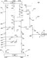
图1是配电网络的图示。Figure 1 is an illustration of a power distribution network.
图2是包括隔离故障段的图1的配电网络的图示。FIG. 2 is an illustration of the power distribution network of FIG. 1 including isolated fault segments.
图3是示出故障段的附近段的单相恢复的图2的配电网络的图示。Fig. 3 is a diagram of the power distribution network of Fig. 2 showing single-phase restoration of a segment in the vicinity of a faulted segment.
图4是示出在配电网络中隔离故障段以及给网络中的一个或多个隔离段恢复供电的方法的实施例的流程图。Figure 4 is a flowchart illustrating an embodiment of a method of isolating a faulted segment in an electrical distribution network and restoring power to one or more isolated segments in the network.
图5是示出图4的方法的另一个实施例的流程图。FIG. 5 is a flowchart illustrating another embodiment of the method of FIG. 4 .
图6是示出图4的方法的另一个实施例的流程图。FIG. 6 is a flowchart illustrating another embodiment of the method of FIG. 4 .
具体实施方式Detailed ways
这里描述了用于描述和控制配电网络的系统和方法的各个实施例。这些系统和方法执行各种功能,包括采用能在其间进行数据交换的分布式逻辑控制器以及多个馈电线电网拓扑来识别配电网络内的一个或多个故障段以及尽可能多地给非故障段恢复供电。这里描述的方法和系统也可根据需要来实现单相,两相或者三相隔离以及恢复。Various embodiments of systems and methods for describing and controlling electrical distribution networks are described herein. These systems and methods perform a variety of functions, including identifying one or more fault segments within a power distribution network using distributed logic controllers capable of exchanging data among them and multiple feeder grid topologies and The power supply of the faulty segment is restored. The methods and systems described herein can also be used to implement single-phase, two-phase or three-phase isolation and restoration as desired.
这里还提供的是自动化的,分布式的,以及模块化的控制应用程序(control application),以及用于在故障事件之后给配电网的段恢复供电的方法。该控制应用程序的各个实施例,诸如计算机程序,描述成其可被提供作为现有网络控制应用程序中的模块。该控制应用程序的实施例还可位于配电网络控制以及管理系统和服务器中的模块中。当配备有该控制应用程序以及与场设备相互作用的任何合适的通信协议以及接口时,该控制应用程序可提供全配电自动化(DA),而不需要专用的主控制器,并且允许扩展配电网络控制,而控制器结构或软件不需要广泛的以及可能的人力密集改变。Also provided herein are automated, distributed, and modular control applications and methods for restoring power to segments of a distribution grid after a fault event. Various embodiments of the control application, such as computer programs, are described such that they can be provided as modules in existing network control applications. Embodiments of the control application may also reside in modules in the distribution network control and management system and server. When equipped with the control application and any suitable communication protocols and interfaces to interact with field devices, the control application can provide full distribution automation (DA) without the need for a dedicated master controller and allows expansion of distribution electrical network control without requiring extensive and possibly labor-intensive changes to the controller architecture or software.
在检测到故障之后,该系统和控制应用程序动作,以隔离故障段并且确定优选路由路径,以给非故障段恢复供电。此外,该系统和方法允许通过在多个控制器和/或变电站之间进行对等通信而从一个或多个可替换电源向非故障段恢复供电,该一个或多个可替换电源诸如相关变电站内的其他电源或者与可替换变电站相关的电源中的其他电源。该控制应用程序可监控配电网络并且能够发布自动重新配置命令给网络内的可控开关,这样在为尽可能多的部分维持供电服务的同时改变了网络拓扑(即,在任何给定时刻跨越布局之内所有部分的所有连接路径),并且隔离了故障。After a fault is detected, the system and control application act to isolate the faulty segment and determine a preferred routing path to restore power to the non-faulty segment. Additionally, the system and method allow restoration of power to a non-faulted segment from one or more alternate sources, such as associated substations, through peer-to-peer communications between multiple controllers and/or substations Other power sources within or associated with alternative substations. The control application can monitor the distribution network and can issue automatic reconfiguration commands to controllable switches within the network such that network topology is changed while maintaining power service to as many segments as possible (i.e., across all connection paths of all parts within the layout) and faults are isolated.
首先参考图1,示例性配电网络整体以100示出。配电网络100包括多个变电站10,20以及30,其每个与一条或多条馈电线相关,所述馈电线示出为11,12,13,21,22和31。每个变电站10,20和30还包括一个或多个断路器,即变电站断路器(或者简称“断路器”)301,311,316,327,328和340,每个断路器连接到馈电线11,12,13,21,22和31中的一条馈电线上。变电站断路器还被描述为“根部(root)”。如本文中所使用的,术语“馈电线(feeder)”指的是输电线或者给网络100的一个或多个部分供电的其他导体。在图1所示的本示例性实施例中,变电站10与馈电线11,12和13相关,每条馈电线分别连接到断路器301,316以及328。变电站20与馈电线21和22相关,每条馈电线分别连接到断路器311和327。变电站30与馈电线31相关,该馈电线31连接到断路器340。尽管仅有三个变电站在该例子中示出,但是网络100可包括任何数量的变电站,每个变电站可包括任何数量的馈电线。Referring first to FIG. 1 , an exemplary power distribution network is shown generally at 100 . The
网络100包括多个节点301-340,每个节点影响网络100的拓扑并且连接一条或多条馈电线的各部分。术语“节点”涉及网络100上任何可寻址(addressable)点。节点301-340可包括诸如电路分割(circuitsplit),传感器或其他测量点的任何类型的场设备,以及诸如断路器或者自动重合闸(recloser)的可控开关。可控开关可以是常闭型的或者常开型的。节点301-340的特征为有源或者无源的。“有源节点”涉及可进行控制以影响拓扑改变的任何节点。有源节点包括自动重合闸,断路器以及可控开关(包括远程可控开关)。有源节点能三相或者单相控制。“无源节点”涉及包括网络分割或者任何不可控项的节点,并且不引起拓扑改变。由于在网络部分内存在重新路由的可能性,因此由于考虑负载容量而需要无源节点。节点还可以限定不同的支路,其中网络中形成的电路分成了多个附加电路。支路可作为单相或多相支路出现。其中出现分割,朝向相关变电站断路器设置的节点可描述成“支路根部”。The
网络100限定了相关“布局”,其涉及网络连接的分布,包括静态和地理分布。网络100还可分成一个或多个“段”或者“干线”,其涉及位于重要的有源或无源网络节点之间的部分馈电线。依据该布线,段能够从跨越多个变电站的多条馈电线接受电力。每个段可具有相关构造的“负载容量”,其表示可由该段处理的最大负载。
再次参考图1,在本示例性实施例中,节点301-340包括无源网络节点,常闭合开关,常打开开关以及传感器。对节点数量并不存在预先配置的限制。节点302,303,307,309,317,319,321,325,326,329,333,334和338为常闭合开关,其可打开以隔离故障段。节点305,312,313,323,335和337为常打开开关,其动作以防止交叉电力传输并限定了网络100的各部分。节点304,306,308,310,315,318,320,322,324,330,332,336以及339为无源网络节点,节点314和331为传感器。网络100的布局,以及本实施例中示出的特定结构类型和数量的节点仅仅是示例性的。本文中所述的系统和方法可应用到具有任何期望拓扑、以及任何数量、类型和结构的节点的任何配电网络。Referring again to FIG. 1 , in this exemplary embodiment, nodes 301-340 include passive network nodes, normally closed switches, normally open switches, and sensors. There is no pre-configured limit on the number of nodes.
网络100还包括多个部分,每个部分可由单条馈电线馈电。术语“部分(sector)”涉及与有限数量的有源节点相关的分布式子网络,所述有源节点诸如断路器,开关和自动重合闸。部分也可称作“电力区”。每个部分可与单条馈电线或者与多条馈电线相关。在一个实施例中,每个部分包括在连接到单条馈电线上的变电站中的单个断路器以及所有常打开开关之间的所有段。部分的“边缘”指的是变电站中的断路器以及常打开开关。在图1所示的本例子中,网络100包括六个部分211,212,213,221,222以及230,每个部分与单条馈电线相关并且由变电站断路器以及至少一个常打开开关来约束。诸如常打开开关之类的限定部分的边缘并连接相邻部分的节点可称作“边缘节点”。The
在图1所示的本例子中,所有段是三相的,即,不存在单相电路。然而,本文中所述的控制应用程序和方法能够单相处理,因此可应用到诸如单相网络之类的非三相网络。In the present example shown in Figure 1, all segments are three-phase, ie there are no single-phase circuits. However, the control applications and methods described herein are capable of single-phase processing and thus are applicable to non-three-phase networks such as single-phase networks.
网络100中的各节点、变电站或者其他部件的位置描述成彼此相关,并且可描述成与和其他节点,断路器,馈电线或变电站相关的网络路径上的它们的位置相关。例如,第一节点描述成在第二节点“以前”或“之前”,在第二节点的“前面”或者在第二节点的“上游”表示当从断路器向该部分的边缘分析电路路径时第一节点位于第二节点之前,即,位于断路器或变电站和第二节点之间。同样,第一节点描述成“下一个节点”,在第二节点“后面”或“之后”,或者在第二节点的“下游”表示当从断路器向该部分的边缘分析电路路径时第一节点在第二节点之后,即,位于第二节点和部分边缘节点之间。The locations of nodes, substations or other components in
每个变电站10,20和30包括控制各个网络节点的相应控制器101,102和103。如图1所示,控制器101包括在变电站10中,控制器102包括在变电站20中,控制器103包括在变电站30中。在一个实施例中,每个控制器101,102和103是分布式自动(DA)控制器。在本实施例中,每个变电站包括一个控制器。然而,如果期望的话,变电站可包括一个以上的控制器。根据需要,每个控制器101,102和103也可用作监测监控及数据采集(SCADA)远程终端设备(RTU)。每个控制器101,102和103以与位于由相应变电站加电的电力段上的有源节点和传感器的客户机-服务器(主-从)关系进行通信。每个控制器101,102和103还配置成与其他控制器进行通信和交换数据。在一个实施例中,控制器和节点之间的通信通过无线网络来实现,该无线网络例如包括与每个控制器和场设备(即,节点)相关的固定IP无线设备。Each
每个控制器101,102和103控制由相应断路器和一个或多个分别打开的开关限定的至少一个部分。在图1所示的例子中,网络100分成部分211,212,213,221,222以及230。部分211具有由断路器301和常打开开关305和312界定的边缘,部分212具有由断路器316和常打开开关312,323和337界定的边缘,部分213具有由断路器328和常打开开关335界定的边缘。部分211,212和213由控制器101进行控制。部分221具有由边缘311和常打开开关305和313界定的边缘,部分222具有由断路器327和常打开开关313和323限定的边缘。部分221和222由控制器102进行控制。部分230具有由断路器340和常打开开关335和337界定的边缘,并由控制器103进行控制。在一个实施例中,每个部分中的所有节点仅发送数据给该部分的相应控制器并仅从该部分的相应控制器接收命令。Each
在一个实施例中,如果给定的变电站不包括控制器,那么其他变电站中的控制器可配置成对接由所述给定的变电站通常覆盖的部分,因而建成“逻辑”控制器。这种配置可以导致产生控制应用程序的完全独立的情形。尽管从控制应用程序的观点来看,物理控制器可呈现为不同的逻辑控制器,但是与相同的变电站相关的多个部分可由相同的物理控制器进行控制。In one embodiment, if a given substation does not include a controller, then controllers in other substations may be configured to interface with the portion normally covered by the given substation, thus creating a "logical" controller. This configuration can result in a completely separate situation for the control application. Although from the point of view of the control application, a physical controller may appear as a different logical controller, multiple parts related to the same substation may be controlled by the same physical controller.
常打开开关可发送数据给常打开开关的任一侧上的控制器并且从这些控制器接收命令(在相同的变电站中的多条馈电线的情形下,这些可包括“逻辑”控制器)。如果这由于常打开开关中的通信协议的限制而是不可以的,那么一个指定的控制器可通过将这标记在控制应用程序结构中而专门负责那个有源节点。The normally open switch may send data to and receive commands from controllers on either side of the normally open switch (in the case of multiple feeders in the same substation these may include "logic" controllers). If this is not possible due to communication protocol limitations in the normally open switch, then a given controller can be dedicated to that active node by marking this in the control application structure.
下文中进一步描述控制器以及相关的控制应用程序和方法。作为例子,控制器的特征将结合控制器101进行描述。然而,这些特征也可应用于控制器102和103,以及应用到适用于任何其他变电站和/或网络的任何其他控制器。The controller and related control applications and methods are further described below. Features of the controller will be described in connection with
控制器101从部分211,212和213中的节点接收数据,并且给这些节点发送数据和/或命令。此外,控制器101配置成与例如控制器102和103的其他控制器交换数据。如果在部分211中出现故障,例如,控制器101可与其他控制器102和103进行通信,以确定控制器102和/或103是否具备给部分211的隔离段供电的能力,并且根据需要,发送适当的请求给控制器102和/或103,以闭合开关并且给隔离段恢复供电。
提供控制应用程序,其可位于一个或多个控制器中并且可由一个或多个控制器执行,以启动通过识别网络中的故障,隔离该故障,并且从一个或多个控制器恢复给隔离段供电来控制网络100的拓扑的过程。Provides a control application, which may reside in and be executed by one or more controllers, to initiate a fault by identifying a fault in the network, isolating the fault, and recovering from the one or more controllers to the isolated segment The process of supplying power to control the topology of the
在一个实施例中,每个部分被控制应用程序认为是控制器实例。此外,在具有多条馈电线并且因而具有多个部分的那些变电站中,控制应用程序可将那个变电站中的控制器表示为多个“逻辑”控制器实例。然后,根据需要在控制器实例中交换数据。如本文中所使用的,“控制器实例(controller instance)”包括由控制应用程序识别的物理或者逻辑控制器。多个控制器(或者控制器实例)可以对等的方式彼此进行通信,并且可通过控制应用程序交换关于它们自己的网络部分的状态的数据。In one embodiment, each part is considered a controller instance by the controlling application. Furthermore, in those substations with multiple feeders and thus sections, the control application may represent the controllers in that substation as multiple "logical" controller instances. Then, exchange data among controller instances as needed. As used herein, a "controller instance" includes a physical or logical controller identified by a control application. Multiple controllers (or controller instances) can communicate with each other in a peer-to-peer fashion and can exchange data about the status of their own network parts through the control application.
在图1所示的例子中,控制应用程序将控制器101,102和103表示为控制器实例。控制器101可表示为控制器实例111,112以及113,其分别控制部分211,212和213。控制器102可表示为控制器实例121和122,其分别控制部分221和222。控制器103可表示为控制器实例131,其控制部分31。In the example shown in FIG. 1, the control application represents
在给定段中出现故障的情形下,控制该故障部分的控制器实例可称作“触发控制器”,其中该故障部分即包括该故障段的部分。触发控制器将隔离该故障,然后通过查询电力可用性以及剩余控制器实例的电路容量限制来查找从相同变电站或者其他变电站恢复供电的可能性,其中所述剩余控制器实例被描述成“对等控制器”。这种请求或者查询可根据预配置的优先权列表来执行。如果需要的话,这种优先权列表可在运行时间上被远距离地改变。对等控制器在从触发控制器接收请求后变成控制应用程序处理的有源部分,并可成为逻辑设备。In the event of a failure in a given segment, the controller instance that controls the failed portion, ie, the portion that includes the failed segment, may be referred to as a "triggering controller". The triggering controller would isolate the fault and then look for the possibility of restoring power from the same substation or other substations by querying the power availability and circuit capacity constraints of the remaining controller instances described as "peer-controlled device". Such requests or queries may be performed according to a pre-configured priority list. This priority list can be changed remotely at runtime, if desired. Peer controllers become an active part of controlling application processing after receiving requests from trigger controllers and can become logical devices.
在本文中所述的系统和方法中不存在单个主控制器。每个控制器实例在电力故障出现在由那个控制器控制的部分中时负责给隔离段恢复供电所需的持续时间。就给上级报告来说,触发控制器可通过等待来自对等控制器的回复,以及根据来自对等控制器的回复指示处理的超时,成功或失败给控制中心和/或用户而保持“主控”属性。在同时故障的情形下,可以是多个控制器动作成“触发控制器”,即,试图恢复供电。There is no single master controller in the systems and methods described herein. Each controller instance is responsible for restoring power to an isolated segment for the duration required when a power failure occurs in the portion controlled by that controller. As far as reporting to a superior is concerned, the triggering controller can remain "master" by waiting for a reply from the peer controller, and indicating the timeout, success or failure of the process based on the reply from the peer controller to the control center and/or the user. "Attributes. In the event of a simultaneous failure, it may be that multiple controllers act to "trigger the controller", ie attempt to restore power.
该控制应用程序可存在于一个或多个控制器中,并且可被执行以完成本文中描述的一个或多个方法。The control application can reside in one or more controllers and can be executed to perform one or more methods described herein.
在一个实施例中,该控制应用程序执行用于通过产生描述该网络的数据来描述网络布局的方法。按照该方法,该控制应用程序将网络结构描述成各个段以及节点。这种结构数据可由该控制应用程序(或者其中的结构工具)转换成动态大小的多维阵列,该多维阵列存储该结构信息。在一个实施例中,该控制应用程序通过存储对应于网络中每个节点的阵列元素而描述该网络布局。对于网络中的每个部分这可顺序执行。因此,每个节点在该阵列中被描述为配置阵列数据,并且每个节点的各个特性或特性可被描述在相关的阵列元素中。In one embodiment, the control application executes a method for describing a network layout by generating data describing the network. According to this method, the control application describes the network structure into individual segments and nodes. This structured data can be converted by the control application (or a structured tool therein) into a dynamically sized multi-dimensional array that stores the structured information. In one embodiment, the control application describes the network layout by storing an array element corresponding to each node in the network. This can be done sequentially for each part in the network. Thus, each node is described in the array as configuration array data, and individual properties or characteristics of each node can be described in the associated array element.
该控制应用程序还可记录来自场设备(例如,有源节点)的实时数据,并且构建阵列组作为位置标志符(placeholder)。这种数据可称作“运行时间阵列数据”。通过参考配置阵列数据来分析运行时间阵列数据,该控制应用程序可确定适当的路由方法,用于给该电网的段(单相或三相)供电。当到达电网极限时,即,该控制应用程序已经对于与相应部分相关的所有节点描述了该结构和运行时间数据,该控制应用程序将通知在其他控制器中运行的相邻应用程序,这样将整个电网以可扩展形式描述在阵列中。The control application can also record real-time data from field devices (eg, active nodes) and build array groups as placeholders. Such data may be referred to as "run-time array data". By analyzing run-time array data with reference to configuration array data, the control application can determine the appropriate routing method for powering segments (single-phase or three-phase) of the grid. When the grid limit is reached, i.e., the control application has described the structure and runtime data for all nodes related to the corresponding section, the control application will notify neighboring applications running in other controllers, so that The entire grid is described in an array in a scalable form.
描述该网络的方法的一个实施例进一步在示例性表1的内容中进行描述,其由该方法产生以描述图1所示的网络100的布局。表1和下面的描述示出为每个节点命名的规则的例子以及代表可进入的每个节点的特性和结构的例子。用于命名各个节点并且显示各个特性和结构的规则,以及所描述的数据值仅仅是示例性的。任何合适的规则可用于收集数据。此外,为每个节点收集的数据类型也是示例性的,并且所述数据类型并不打算进行限制。One embodiment of a method of describing the network is further described in the context of exemplary Table 1, which results from the method to describe the layout of
描述方法包括描述与相应馈电线相关的每个网络部分,以及以在断路器开始和在该部分的边缘节点结束的顺序单独描述每个节点,直到所有的常打开开关达到那条馈电线为止。每个节点的结构可如表1所示那样来描述和编译。示例性的名字和数据值描述如下。The description method consists in describing each network section in relation to the corresponding feeder, and describing each node individually in order starting at a circuit breaker and ending at an edge node of that section, until all normally open switches reach that feeder. The structure of each node can be described and compiled as shown in Table 1. Exemplary names and data values are described below.
表1Table 1
如表1所示,列“DAC#(S)”表示用于参考节点的指定控制器数目。在一些实施例中,每个变电站存在一个物理控制器,但是在存在一个以上的情形下,存在两个不同的数目。对于不具有任何物理控制器的变电站,该控制应用程序在现有的控制器之一中产生不同编号的逻辑(“类似馈电线”)实例。As shown in Table 1, the column "DAC#(S)" indicates the designated controller number for the reference node. In some embodiments, there is one physical controller per substation, but where there is more than one, there are two different numbers. For substations that do not have any physical controllers, the control application creates a different numbered logical ("feeder-like") instance in one of the existing controllers.
列“馈电线#(F)”表示给定控制器中的指定馈电线数目,并且涉及给参考节点供电的馈电线。每条馈电线可对应于相关的控制器实例。The column "Feeder #(F)" represents the specified feeder number in a given controller and refers to the feeder feeding the reference node. Each feeder may correspond to an associated controller instance.
列“节点#(N)”用于进入参考节点的名字。在该例子中,每个单独的节点被指定名称“nx”,诸如n1,n2等等。为方便起见,“n0”通常是变电站中的断路器,尽管可以采用其他期望的命名规则。The column "Node#(N)" is used to enter the name of the reference node. In this example, each individual node is assigned a name "nx", such as n1, n2, and so on. For convenience, "n0" is typically a circuit breaker in a substation, although other desired naming conventions may be used.
列“节点类型(T)”表示节点类型。示例性指示符可包括:The column "node type (T)" indicates the node type. Exemplary indicators may include:
B3=断路器,仅仅三相控制,B3 = circuit breaker, three-phase control only,
B31=断路器,具有单相控制能力的三相B31 = circuit breaker, three-phase with single-phase control capability
S3=远程可控开关,仅仅三相控制S3 = remote controllable switch, only three-phase control
S31=远程可控开关,具有单相控制能力的三相S31 = Remotely controllable switch, three phase with single phase control capability
S1=远程可控开关,单相S1 = remote controllable switch, single phase
R3=远程可控自动重合闸,仅仅三相控制R3 = remote controllable automatic reclosing, only three-phase control
R31=远程可控自动重合闸,具有单相控制能力的三相R31 = Remote controllable automatic reclosing, three-phase with single-phase control capability
R1=远程可控自动重合闸,单相R1 = remote controllable automatic reclosing, single phase
P=无源节点P = passive node
M=传感器M = sensor
X=不可控远程开关X = Uncontrollable remote switch
如果该部分由于其各个段中的同源负载容量而不要求描述无源节点,或者不要求描述传感器或者不可控元件,那么这种节点不需要进入。此时,负载容量将是P,X,M节点之间所有段之中的最低的一些。在一个实施例中,位于网络部分的“末端”(但不终止于边缘)的无源节点不需要进行标记,和为控制应用程序考虑负责,这是因为没有额外的电力通过这些无源末端节点进行路由。“末端”节点指的是在其之后不具有大量节点的节点。If the section does not require the description of passive nodes due to homogeneous load capacity in its various segments, or does not require the description of sensors or uncontrollable elements, then such nodes need not be entered. At this point, the load capacity will be the lowest among all segments between P, X, M nodes. In one embodiment, passive nodes located at the "end" (but not terminating at the edge) of a network section need not be tagged and accounted for for control application considerations, since no additional power is passed through these passive end nodes for routing. A "terminal" node refers to a node that does not have a large number of nodes after it.
列“包含三相保护吗?(3P)”表示该参考节点是否包含保护元件,这些保护元件将在恢复单相或多相之前要求设定改变。该控制器实例可采用这种标记来请求单相保护设定改变,并从该参考节点接收回确认。The column "Does Three-Phase Protection Contain? (3P)" indicates whether this reference node contains protection elements that would require a setting change before restoring single or multiple phases. The controller instance can use this flag to request a single phase protection setting change and receive an acknowledgment back from the reference node.
列“(L)之后的该段的最大负载容量”表示可由该参考节点和紧跟在参考节点之后并且在下一个节点之前的段(即,该段紧跟着该参考节点并且在参考节点的远离断路器的一侧上)所支持的最大电流。进入到该列中的这些值可在执行负载容量计算时使用。The column "maximum load capacity of the segment after (L)" indicates the segment that can be loaded by the reference node and the segment immediately after the reference node and before the next node (i.e., the segment immediately following the reference node and The maximum current supported on one side of the circuit breaker. These values entered into this column are used when performing load capacity calculations.
列“它能测量电压吗?(V)”表示该有源节点在运行时间上是否可提供电压测量。可采用下面的值:The column "Can it measure voltage? (V)" indicates whether the active node can provide voltage measurement at runtime. The following values can be used:
0=否0 = no
1=是,分别针对三相中的每相1=Yes, separately for each of the three phases
3=是,所有三相共用一个值3 = Yes, one value for all three phases
A,B,C=仅用于所指示的相A, B, C = for indicated phases only
列“它能测量负载吗?(M)”表示该有源节点在运行时间上是否能提供负载(电流)测量。可采用下面的值:The column "Can it measure load? (M)" indicates whether the active node is capable of providing load (current) measurement at runtime. The following values can be used:
0=否0 = no
1=是,分别对于三相中的每相1 = Yes, separately for each of the three phases
3=是,所有三相共用一个值3 = Yes, one value for all three phases
A,B,C=仅用于所指示的相A, B, C = for indicated phases only
列“它能不跳闸而提供故障指示吗?(A)”表示即使开关位置保持闭合,该有源节点是否可在运行时间提供故障指示。可使用下面的值:The column "Can it provide fault indication without tripping? (A)" indicates whether the active node can provide fault indication during runtime even if the switch position remains closed. The following values can be used:
0=否0 = no
1=是,分别对于三相中的每相1 = Yes, separately for each of the three phases
3=是,所有的三相共用一个值3 = yes, all three phases share one value
A,B,C=仅用于所指示的相A, B, C = for indicated phases only
例如可由自动重合闸的“报警”情形得到不跳闸的故障指示。A non-trip fault indication can be obtained, for example, from an "alarm" condition of an auto-recloser.
列“用户优先级(Y)”表示指定给紧跟在相关节点之后的每个段的优先值。例如,“NULL(零)”表示该优先级没有,数字表示优先级,值“1”表示最低优先级。可在运行时间上采用这种信息以确定其中可用电力并不足以恢复对紧跟着该故障段的所有隔离段的供电时的最佳隔离。至少在边缘段中提供不同的优先级可使用户在该控制应用程序决定过程上进行用户控制。The column "User Priority (Y)" represents the priority value assigned to each segment immediately following the relevant node. For example, "NULL (zero)" indicates that there is no priority, a number indicates a priority, and a value of "1" indicates the lowest priority. This information can be employed at runtime to determine optimal isolation where available power is insufficient to restore power to all isolated segments following the faulted segment. Providing different priorities in at least the edge segments allows user control over the control application decision process.
列“下一个节点#或者DAC #/优先级#(E)”表示在从断路器向该部分的边缘分析该电路路径时紧跟着参考节点的下一个或多个节点。该值可包括节点编号,多个节点编号,“末端“(电路的末端,即在该当前节点之后不存在明显的东西),以及控制器编号(即,DAC#)以及恢复的相关优先级。例如,值1可表示最高优先级。The column "next node # or DAC #/priority # (E)" indicates the node or nodes immediately following the reference node when analyzing the circuit path from the circuit breaker to the edge of the section. The value may include a node number, a number of node numbers, an "end" (the end of the circuit, ie there is nothing obvious after this current node), and a controller number (ie, DAC#) and associated priority for recovery. For example, a value of 1 may represent the highest priority.
采用上面的方案,任何类型的网络布局可以非常简单的术语精确描述。同样,每个部分的布局可描述成所有控制器实例中相同的节点。属于一个控制器的部分的改变将不要求重新构建其他控制器中的结构。Using the scheme above, any type of network layout can be precisely described in very simple terms. Likewise, the layout of each section can be described as the same node in all controller instances. Changes to parts belonging to one controller will not require rebuilding structures in other controllers.
在一个实施例中,该控制应用程序可采用配置阵列数据,诸如上面在表1中所提供的,以构建描述每个网络部件特性的数据阵列。这种阵列可以不限制联络线,段,馈电线或者变电站的数量。网络结构的描述将通过与每个控制器实例相关的网络部分拓扑的简单描述来实现。每个控制器实例不需要知道与对等控制器相关的部分的结构,这是因为预期的消息交换采用了相同的命名规则。In one embodiment, the control application may take configuration array data, such as provided above in Table 1, to construct a data array describing the characteristics of each network element. This array can be unlimited in the number of tie lines, sections, feeders or substations. The description of the network structure will be achieved by a simple description of the topology of the network parts associated with each controller instance. Each controller instance does not need to know the structure of the part related to the peer controller, because the expected message exchange adopts the same naming convention.
在一个实施例中,该控制应用程序以不同的阵列描述了网络,以及其各个部分。这些部分包括邻接段,表示最好电力路由能力的段路径,不能接受额外电力传送的段,以及新的或者修改的网络拓扑。In one embodiment, the control application describes the network, and its various parts, in distinct arrays. These sections include adjacent segments, segment paths representing best power routing capabilities, segments that cannot accept additional power delivery, and new or modified network topologies.
在结合表1所提供的并且对应图1的例子中,控制器101被指定控制器编号“DAC 1”,控制器102被指定控制器编号“DAC 2”,控制器103被指定控制器编号“DAC 3”。提供表2以演示根据本例子的给定给网络100中的每个节点的示例性名称。如上所述,每个断路器被给出名称“n0”,并可由其相关的DAC和馈电线编号来标识。In the example provided in connection with Table 1 and corresponding to Figure 1,
表2Table 2
例如上面结合表1所述的,该控制应用程序可采用配置阵列数据,构造具有配置成表示每个节点的各种特性的参数的附加阵列元素。这些特性可包括但不局限于有源节点的名称,前面的节点,后面的节点,节点是否是支路节点,节点类型,隔离优先级,节点是否具有三相保护,最大负载容量,运行时间电压,实时负载,故障之前的负载值,运行时间开关位置,故障之前的最后位置,以及自动重合闸闭锁指示。For example, as described above in connection with Table 1, the control application may take configuration array data to construct additional array elements with parameters configured to represent various properties of each node. These characteristics can include but are not limited to the name of the active node, node ahead, node behind, whether the node is a branch node, node type, isolation priority, whether the node has three-phase protection, maximum load capacity, run-time voltage , real-time load, load value before fault, running time switch position, last position before fault, and automatic reclosing lockout indication.
下面的例子示出了控制应用程序为一个或多个节点构建的阵列元素的例子。这个例子还描述了各种数据元素的示例性命名规则。在该例子中,该控制应用程序包括以A(s,f,n)的形式构建数据阵列的结构工具,其中s=变电站#,f=馈电线#,n=节点编号。节点编号“n”或者“nx”可用于描述网络中的任一节点,包括诸如开关之类的有源节点以及诸如传感器之类的无源节点。“0”(零)可用于标识参考变电站中的断路器。The example below shows an example of an array element that a control application builds for one or more nodes. This example also describes exemplary naming conventions for various data elements. In this example, the control application includes a structure tool for constructing data arrays in the form A(s, f, n), where s = substation #, f = feeder #, n = node number. The node number "n" or "nx" can be used to describe any node in the network, including active nodes such as switches as well as passive nodes such as sensors. A "0" (zero) may be used to identify a circuit breaker in the reference substation.
每个阵列元素A(s,f,n)可具有各种参数,这些参数由下面的数据元素表示,并在示例性阵列命名规则中呈现为:Each array element A(s, f, n) may have various parameters represented by the following data elements and presented in the exemplary array nomenclature as:
{name,d,e,r,t,y,3p,l,va,vb,vc,ia,ib,ic,ja,jb,jc,qa,qb,qc,ka,kb,kc,za,zb,zc,ba,bb,bc}{name, d, e, r, t, y, 3p, l, va, vb, vc, ia, ib, ic, ja, jb, jc, qa, qb, qc, ka, kb, kc, za, zb , zc, ba, bb, bc}
每个数据元素描述如下。Each data element is described below.
“name”指的是参考节点的名称,编号或者描述,其可从用户输入得到,诸如进入到表1中的那些。"name" refers to the name, number or description of the reference node, which may be obtained from user input, such as those entered in Table 1.
“D”指的是一个或多个前面的开关或其他节点,其每个可表示在如“A(s,f,n)”的阵列命名规则中。对于在网络中不具有前面节点的断路器,这种特性将为NULL。这个值可由控制应用程序来计算。"D" refers to one or more preceding switches or other nodes, each of which may be represented in an array nomenclature such as "A(s,f,n)". For circuit breakers that have no preceding nodes in the network, this property will be NULL. This value can be calculated by the controlling application.
“E”指的是紧跟着参考节点的一个或多个开关或其他节点,其可表示在如“A(s,f,n)”的阵列命名规则中。这个值可由控制应用程序以直接寻址阵列识别的形式计算出。值“end”表示当前节点在该部分的末尾。指定给边缘节点的“DAC x/p”是指示具有优先级p的另一个DAC x的指针。例如,图1的节点n(1,1,n4)代表部分211边缘处的节点305,其由馈电线11馈电。根据这个例子,节点305因此具有E(1,1,DAC2/1)的“E”值,其中“DAC2/1”表示控制器DAC 2具有的优先级为1。如果期望的话,这个值可由该控制应用程序来重新计算成某种更恰当的机器可读取类型。"E" refers to one or more switches or other nodes immediately following the reference node, which may be represented in an array naming convention such as "A(s,f,n)". This value can be calculated by the controlling application in a form recognized by the direct addressing array. A value of "end" indicates that the current node is at the end of the section. "DAC x/p" assigned to an edge node is a pointer indicating another DAC x with priority p. For example, node n(1,1,n4) of FIG. 1 represents
“R”表示参考节点是否与支路接界。对于除了直接与支路接界的那些节点之外的所有节点,这个值将是NULL(或0)。支路内部的无源节点还可被指定值R=NULL(或0)。该控制应用程序可计算这个值用于快速识别各部分中的分裂,以及与分裂段(支路)接界的所有有源节点。在这个实施例中,当从断路器开始时,该控制应用程序将发现作为支路根部的第一节点。如果该支路根部节点不是有源节点(即,该节点类型是诸如S31或R31之类的S或R型之外的类型),那么该控制应用程序将确定断路器和该无源支路根部节点之间的部分中的最近的有源节点(即,上游)。在该例子中,指定这个节点的值为“Nbr”。然后该控制应用程序确定向常打开开关(即,下游)构成分裂边界的所有有源节点。下游边界节点可被指定诸如“Nb1”,“Nb2”等的值。对于Nbr节点,“R”可具有表示下游边界节点Nb1,Nb2等的ALL的值,其形式为:"R" indicates whether the reference node is bordered by a branch. This value will be NULL (or 0) for all nodes except those directly bordering a branch. Passive nodes inside branches may also be assigned the value R=NULL (or 0). The control application can calculate this value for quick identification of splits in each section, and all active nodes bordering the split segments (branches). In this embodiment, when starting from the circuit breaker, the control application will find the first node that is the root of the branch. If the branch root node is not an active node (i.e., the node type is other than type S or R such as S31 or R31), then the control application will determine the breaker and the passive branch root node The nearest active node (ie, upstream) in the section between nodes. In this example, specify the value of this node as "Nbr". The control application then determines all active nodes that form a split boundary to the normally open switch (ie, downstream). Downstream boundary nodes may be assigned values such as "Nb1", "Nb2", etc. For Nbr nodes, "R" can have a value representing ALL of downstream boundary nodes Nb1, Nb2, etc., in the form:
R(s,f,Nbr)={(s,f,Nb1),(s,f,Nb2),etc.}R(s, f, Nbr) = {(s, f, Nb1), (s, f, Nb2), etc.}
这些值是下游有源节点的“地址”,即,该支路的下游边界的“地址”。在这种命名规则中,支路根部有源节点通常具有至少两组。对于每个下游边界节点(Nb1,Nb2,等),“R”将具有负值,直接指向支路根部有源节点。例如:These values are the "address" of the downstream active node, ie the "address" of the downstream boundary of the branch. In this naming rule, branch root active nodes usually have at least two groups. For each downstream boundary node (Nb1, Nb2, etc.), "R" will have a negative value, pointing directly to the branch root active node. For example:
R(s,f,Nb1)={-(s,f,Nbr)}R(s, f, Nb1) = {-(s, f, Nbr)}
R(s,f,Nb2)={-(s,f,Nbr)}R(s, f, Nb2) = {-(s, f, Nbr)}
下游支路边界有源节点通常仅具有一组(仅可以存在一个支路根部)。There is usually only one set of downstream branch boundary active nodes (only one branch root can exist).
“T”指的是节点类型,其可从用户输入得到。"T" refers to the node type, which can be obtained from user input.
“Y”指的是隔离优先级,其可从用户输入得到。"Y" refers to the isolation priority, which can be obtained from user input.
“3P”表示当前节点是否包含三相保护,该三相保护要求设置值对于单相或两相处理而改变。这个值可从用户输入得到。"3P" indicates whether the current node includes three-phase protection, which requires setting values to be changed for single-phase or two-phase processing. This value can be obtained from user input.
“L”指的是最大负载容量,其可从用户输入得到。"L" refers to the maximum load capacity, which can be obtained from user input.
“Va”,“Vb”,“Vc”指的是运行时间上采集的每相(即,相a,b和c)的参考节点中的实时电压。该控制应用程序可采用这些字段来确定这些值是否对于三相(对于V=1),具有一个公共值的三相(V=3),一相或多相的单个值(V=A,AB等等),或者不可用(V=0)是否不同。"Va", "Vb", "Vc" refer to the real-time voltages in the reference nodes of each phase (ie, phase a, b and c) collected over runtime. The control application can use these fields to determine whether the values are for three phases (for V=1), three phases with a common value (V=3), single values for one phase or multiple phases (V=A, AB etc.), or not available (V=0) is different.
“Ia”,“Ib”,“Ic”指的是运行时间上采集的每相实时负载(即,被测电流)。该控制应用程序可采用这些字段来确定这些值对于三相(对于M=1),具有一个公共值的三相(M=3),一相或多相的单个值(M=A,AB等等),或者不可用(M=0)是否不同。"Ia", "Ib", and "Ic" refer to the real-time load (ie, the measured current) of each phase collected at runtime. The control application can use these fields to determine the values for three phases (for M=1), three phases with a common value (M=3), individual values for one or more phases (M=A, AB, etc. etc.), or not available (M=0) is different.
“Ja”,“Jb”,“Jc”指的是故障之前每相的实时负载测量。在运行时间上,该控制应用程序将存储该字段中最后的负载值(I),其刚好在故障之前被记录。"Ja", "Jb", "Jc" refer to the real-time load measurement of each phase before the fault. At runtime, the control application will store the last load value (I) in this field, which was recorded just before the failure.
“Qa”,“Qb”,“Qc”指的是每相的参考节点的运行时间位置。这些标记可被指定表示“打开”或“闭合”的值,例如:打开=0,闭合=1。该控制应用程序可采用这些字段来根据T值(S1,S3,S31,R1,R3,R31)确定这些值对于所有相中的每相或者公共值是否不同。"Qa", "Qb", "Qc" refer to the runtime position of the reference node for each phase. These flags can be assigned values representing "open" or "closed", eg: open=0, closed=1. The control application can use these fields to determine from the T values (S1, S3, S31, R1, R3, R31) whether these values are different for each of all phases or a common value.
“Ka”,“Kb”,“Kc”指的是故障之前的参考节点的每相的最后位置(Q)。在运行时间上,该控制应用程序将存储正好在故障之前该字段中的最后位置值。"Ka", "Kb", "Kc" refer to the last position (Q) of each phase of the reference node before the fault. At runtime, the control application will store the last position value in this field just before the fault.
“Za”,“Zb”,“Zc”指的是每相的实时故障指示(例如,真=1,假=0)。该控制应用程序可在运行时间上填入(populate)对应的值。该控制应用程序可采用这些字段来确定这些对应的值对于三相(A=1),具有一个公共值得三相(A=3),单个值(A=A,AB等等),或者不可用(A=0)是否不同。"Za", "Zb", "Zc" refer to real-time fault indications for each phase (eg, true=1, false=0). The control application can populate the corresponding values at runtime. The control application can use these fields to determine the corresponding values for three phases (A=1), three phases with a common value (A=3), individual values (A=A, AB, etc.), or not available (A=0) is different.
“Ba”,“Bb”,“Bc”指的是每相自动重合闸的实时闭锁指示(例如,真=1,假=0)。该控制应用程序可在运行时间上采用对应的值填入这个标记。该控制应用程序可采用这个标记来根据T值(R1,R3,R31)确定该闭锁指示值是否是不同的三相值或者是基于共同的三相值。"Ba", "Bb", "Bc" refer to the real-time blocking indication of auto-recloser for each phase (eg, true=1, false=0). The control application can fill this tag with the corresponding value at runtime. The control application can use this flag to determine from the T value (R1, R3, R31) whether the lockout indication values are different three-phase values or are based on a common three-phase value.
在一个实施例中,常打开开关(例如,边缘节点)在相邻的控制器实例中采用相同的名称,这样当通过名称进行引用时,任一个控制器实例均将通常访问常打开开关。这种共同的命名规则使得每个控制器容易并且精确地识别控制器之间对等请求中引用的常打开开关。In one embodiment, an always-on switch (eg, an edge node) takes the same name in adjacent controller instances, such that when referenced by name, either controller instance will normally access the always-open switch. This common naming convention allows each controller to easily and precisely identify always-open switches referenced in peer-to-peer requests between controllers.
图4示出用于响应故障的网络拓扑的自动重新配置的方法400,其包括一个或多个阶段405-455,并且其可通过执行与在相应部分经历故障的网络控制器相关的控制应用程序而实现。该方法通过与其他控制器进行通信以重新路由各段(以及用户)给其他电力馈电线而给尽可能多的段维持最大电力服务的同时隔离一个或多个故障段。该控制应用程序为配电网自动确定新的合适的拓扑。故障可以是三相的或者单相的,并且该方法能根据节点的结构和性能来恢复三相段中的电力,以及各相中的电力。FIG. 4 illustrates a method 400 for automatic reconfiguration of a network topology in response to a failure, comprising one or more stages 405-455, and which may be implemented by executing a control application associated with a network controller experiencing a failure in a corresponding portion And realize. This method isolates one or more faulty segments while maintaining maximum electrical service to as many segments as possible by communicating with other controllers to reroute segments (and customers) to other power feeders. The control application automatically determines a new suitable topology for the distribution network. Faults can be three-phase or single-phase, and the method can restore power in three-phase segments, as well as power in individual phases, depending on the structure and performance of the nodes.
在一个实施例中,该控制应用程序的实例在每个控制器中运行并且一直监测所有的值,这些值包括每个节点中的负载以及部分中的每个节点的开关位置,以及存储至少该负载的紧接(immediate)在前的时间历史以及每个节点的开关位置。为每个网络部分可提供一个控制器实例。In one embodiment, an instance of the control application runs in each controller and constantly monitors all values including load in each node and switch position for each node in a section, and stores at least the The immediate previous time history of the load and the switch position of each node. One controller instance can be provided for each network part.
在阶段405,该控制应用程序发现故障。这可通过从有源节点接收故障指示或者触发状态而实现。触发状态可包括一个或多个节点中的电压损失,变电站的跳闸以及自动重合闸的闭锁,以及部分中的自动重合闸的跳闸和闭锁。在一个例子中,结合图2进行描述,与控制器实例112(下文中称作“控制器112”)相关的控制应用程序实例检测节点317,319以及321之间的段中的故障,如图2所示。该故障指示的形式可以是从自动重合闸开关317发送的故障指示,通过开关317,319以及321的电压降检测,和/或开关317的跳闸和闭锁打开的检测。At
在一个实施例中,如果该控制应用程序检测到节点(单相或多相)中的电压损失,那么它也将注意相邻节点的相同相,相邻节点的所有相,或者该部分中的所有相。中等节点而不是更高节点中的单个电压损失可被警报成设备故障,并且将不触发隔离(还称作“分段”)或恢复程序,如方法400中所描述的那样。在另外的实施例中,如果故障引起断路器在自动重合闸打开之前跳闸(如果断路器与一个或多个自动重合闸串联连接),则该控制应用程序将识别出这种指示错误地暗示该故障在自动重合闸“之前”。该控制应用程序将通过监测指示故障但是还没有跳闸的自动重合闸点而进行补偿。如果这些点不可用,或者这种监测失败,该控制应用程序将故障指示器放置在常打开开关(边缘节点)所在的地方,这样当常打开开关闭合以恢复给隔离段进行供电时,该控制应用程序将发现故障上的闭合,然后重新评价该情形。在另一个实施例中,如果其中一条主变电站馈电线由于馈送到该变电站中的断路器的高压损失而损失时,该控制应用程序将通过监测部分的有源节点中的多个电压损失,或者在常打开开关(如果常打开开关包括电压传感器)检测到这种情形,并且触发隔离以及恢复方法400。In one embodiment, if the control application detects a voltage loss in a node (single-phase or multi-phase), it will also take note of the same phase of the adjacent node, all phases of the adjacent node, or the All phases. A single loss of voltage in a middle node but not a higher node may be alarmed as a device failure and will not trigger an isolation (also referred to as “segmentation”) or recovery procedure, as described in method 400 . In a further embodiment, if a fault causes the circuit breaker to trip before the auto-recloser opens (if the circuit breaker is connected in series with one or more auto-reclosers), the control application will recognize that such an indication falsely implies the The fault was "before" the auto-recloser. The control application will compensate by monitoring reclose points that indicate a fault but have not yet tripped. If these points are not available, or if this monitoring fails, the control application places a fault indicator where the normally open switch (edge node) is located so that when the normally open switch closes to restore power to the isolated segment, the control application The application will find a closure on the fault and then re-evaluate the situation. In another embodiment, if one of the main substation feeders is lost due to a loss of high voltage feeding a circuit breaker in that substation, the control application will monitor the voltage losses in the active nodes of the portion, or This situation is detected at the normally open switch (if the normally open switch includes a voltage sensor) and triggers the isolation and recovery method 400 .
在阶段410中,在发现故障时,该控制应用程序(或者位于所影响的变电站控制器中的控制应用程序实例)将冻结(freeze)并且使得该中间预故障时间历史值对于所有的节点保持原样。该控制器实例,即,触发控制器,将读取报告故障的所有节点并且确定故障之前最后的有源节点,即,在断路器和该故障之间的与该故障最接近的有源节点。例如,最后的有源节点称作“节点n0”,并且可在命名规则中被表示为A(s0,f0,n0)或者n(s0,f0,n0)。在本实例中,控制器112中止记录部分212中节点的运行时间值,保持每个节点的历史值,并且确定节点317是“节点n0”。In
在阶段415中,触发控制器可确定该故障是单相还是多相的。如果在具有单相容量并且位于该断路器和节点n0之间的至少一个节点的全部三相中报告故障,那么认为该故障是三相的。如果由断路器和节点n0之间具有单相容量的所有节点仅报告单相或两相故障,那么确定该故障为单相或两相的。如果该故障每侧上的有源节点不具有单相容量(即,所有相都被共同控制),那么单相或两相故障也作为三相故障处理。In
然后触发控制器通过启动隔离以及恢复程序来继续处理该故障,以便给尽可能多的段(以及相关用户)恢复供电。在一个实施例中,该控制应用程序一次仅处理一个部分中的一个故障。然而,多个控制器或者控制器实例可以非常快的顺序单独处理多个故障,因此向终端用户呈现为“同时的”。The trigger controller then continues to process the fault by initiating isolation and restoration procedures to restore power to as many segments (and associated customers) as possible. In one embodiment, the control application only handles one failure in one section at a time. However, multiple controllers or controller instances can individually handle multiple faults in very rapid sequence, thus appearing "simultaneously" to the end user.
在阶段420中,触发控制器启动隔离程序以隔离该故障。该触发控制器111可发布广播消息给所有的其他控制器,即,对等控制器,从而通知它们该事件。这种广播可以采用给所有对等控制器的任何消息格式,而不必采用特定的形式。该广播并不局限于互联网协议网络中所知道的广播形式。In
该触发控制器通过打开故障段周围合适的节点而隔离该故障段。特别是,该触发控制器打开了该故障段之前最后的有源节点,以及紧接在该故障段之后的所有有源节点。在一个实施例中,如果节点n0是支路根部,那么紧接在该故障段之后的所有有源节点打开。在本例子中,控制器112打开节点317,319和321,以隔离故障段,如图2所示。The trigger controller isolates the faulty segment by opening appropriate nodes around the faulty segment. In particular, the trigger controller turns on the last active node before the fault segment, and all active nodes immediately following the fault segment. In one embodiment, if node n0 is the branch root, then all active nodes immediately following the faulted segment are turned on. In this example,
然后触发控制器启动恢复程序,其可以在两个阶段中实现。第一阶段恢复响应负责给故障段“之前”(即,断路器和故障段之间)的段恢复供电,其中故障段“之前”的段不包括故障相段。第二阶段恢复负责给故障段“之后”的段恢复供电,其中故障段“之后”的段不包括该故障段。The controller is then triggered to initiate a recovery procedure, which can be implemented in two stages. The first phase restoration response is responsible for restoring power to segments "before" the faulted segment (ie, between the circuit breaker and the faulted segment), where segments "before" the faulted segment do not include the faulted phase segment. The second stage of restoration is responsible for restoring power to segments "after" the failed segment, where the segment "after" the failed segment does not include the failed segment.
在阶段425中,触发控制器通过闭合断路器和节点n0之间的有源节点的所有相并且通过闭合该断路器而给故障段之前的所有段恢复供电。在该实施例中,控制器112仅仅闭合断路器316,这是因为在断路器316和节点317之间不存在有源节点。In
然后触发控制器继续启动恢复程序以使得其中故障段结束的一个或多个节点和该部分边缘之间尽可能多的隔离段恢复供电。在阶段430,触发控制器识别对等控制器,该对等控制器包括能连接成给隔离段恢复供电的电路。在本例子中,控制器112识别对等控制器111,122,以及131。The controller is then triggered to continue the restoration procedure to restore power to as many isolated segments as possible between the node or nodes where the failed segment ended and the edge of the portion. At
在阶段435中,为了恢复给这些段供电,触发控制器发布请求给管理边缘节点的对等控制器,所述边缘节点可闭合以给隔离段供电。如果发现了多个对等控制器,如果最高优先级的对等控制器不够(由于对等部分中的电力限制,或者在将要恢复的这些段的能力之内)那么可分配提供给隔离段的电力。触发控制器可发送电力可用性信息的请求给所发现的全部对等控制器。该触发控制器从每个对等控制器接收回应,并且从最高优先级对等控制器到最低优先级对等控制器逐渐启动,确定每个控制器是否能提供隔离段所请求的足够电力。In
在阶段440中,每个对等控制器然后可根据每个对等控制器可提供的最大负载,并根据对等控制器和隔离段之间的流动路径中这些段的电力能力肯定或者否定地响应。例如,如果对等控制器可提供电力给隔离段而不超过其最大负载,那么它将肯定地响应。同样,如果给超过最大负载的那些段恢复供电,那么对等控制器将否定地响应。In
在一个实施例中,如果存在多个选择(多个边缘节点由一个对等或由多个对等来闭合),那么该触发控制器一次发送一个请求消息。选择的顺序可由在配置时间进入到该结构中的优先级来确定。在另一个实施例中,即使是连接到两侧上相同控制器的边缘节点,该触发控制器仅需要参考边缘节点名称(编号),这是因为该消息包含了原始馈电线名称(编号)。这方面使得与一个控制器相关的部分和馈电线可以重新配置,而不要求对等控制器中的重新配置。In one embodiment, if there are multiple options (multiple edge nodes closed by one peer or by multiple peers), the trigger controller sends one request message at a time. The order of selection may be determined by the priority entered into the structure at configuration time. In another embodiment, even if it is an edge node connected to the same controller on both sides, the triggering controller only needs to refer to the edge node name (number) because the message contains the original feeder name (number). This aspect enables reconfiguration of sections and feeders associated with one controller without requiring reconfiguration in the peer controller.
如果对等控制器肯定地响应,那么对等控制器可提供足够的电力。然后该控制应用程序可确定从每个对等控制器到该隔离段的电力流中的每个段是否可处理由该对等控制器提供的电力。If the peer controller responds affirmatively, then the peer controller may provide sufficient power. The control application can then determine whether each segment in the power flow from each peer controller to the isolated segment can handle the power provided by the peer controller.
在阶段445,如果对等控制器肯定地响应,并且对等控制器和隔离段之间的所有段和节点可以处理所要求的负载,该控制应用程序继续闭合恰当的节点,以给受影响的段提供电力。At
再次参考图2,在本例子中,控制器112发布提供负载到321,323,和327之间的段的电力可用性的请求给对等控制器122和131。优选的是,以根据所期望的优先级设置的顺序来发布这些请求给每个对等控制器。该控制应用程序确定控制器122可提供足够的电力以及控制器122和隔离段之间的流动路径中的段可以处理由控制器122提供的电力。因此,响应控制器112的请求,控制器122闭合开关323,并提供电力给节点323和故障段之间的段。在一个实施例中,在对等控制器未直接闭合该联络线(tie)的情形下(在配置时间确定),实际闭合指令可通过触发控制器在SCADA中路由;该控制应用程序功能未改变,仅仅是在SCADA中路由。Referring again to FIG. 2 , in this example,
可替换地,该控制应用程序可首先确定隔离段能处理来自对等控制器的电力,然后发布电力可用性以及闭合边缘节点的同时要求。例如,从触发控制器112到对等控制器122的请求可以是“我是DAC=1,馈电线=2-你可以闭合联络线=n19以及在各相(A,B,C)上提供负载=y吗?如果是-操作(I am DAC=1,Feeder=2-can you close tie=n19 andsupply a load=y on phases(A,B,C)?If YES-do it)”的形式。对应优先级为2(高于控制器DAC 3的优先级,控制器DAC 3的优先级为1)的DAC 2的对等控制器122由控制器112发送第一请求。控制器122然后通过接受该请求并且闭合对应的边缘节点,以及用“ACK”响应触发控制器来或者否定地(例如,“否,不能操作/NACK”的形式)或者肯定地响应。如果对等控制器122不能接受,那么它可以“NACK,y2”的形式响应,其中y2是对等控制器可提供的最大负载。可替换地,控制器112可发送上面的请求给对等控制器122,并且对等控制器122确定其自身的电力容量以及响应之前的隔离段的容量。Alternatively, the control application may first determine that the isolated segment can handle power from the peer controller, and then issue power availability and simultaneous requirements to close edge nodes. For example, a request from
在阶段450中,如果在故障段中存在支路,那么该控制应用程序对于剩余的隔离段重复该程序。结果将一个接一个地闭合联络线,或者使得某些联络线保持打开。在本例子中,该控制应用程序执行与上述执行的相同的程序,以恢复312和319之间的段的供电。此时,仅存在一个可用的对等控制器,即,控制器111。如上所述,该控制应用程序确定控制器111是否能提供足够的电力,并且确定控制器111和节点319之间的电力流中的所有段是否能处理所提供的电力。在该例子中,该控制应用程序进行肯定确定,并且控制器111闭合开关(边缘节点)312,以提供电力给剩余的段。In
参考图5,在电力容量不能从任何一个对等控制器提供时,或者如果该电力流路径中的一个或多个段不能处理所要求的电力容量,该控制应用程序将以方法500继续,以减小将要恢复的段的数量,或者如果可提供多个对等控制器(实际的或者逻辑的),该控制应用程序可将提供给多个控制器之间的隔离段的电力进行分割。Referring to FIG. 5, when power capacity is not available from any of the peer controllers, or if one or more segments in the power flow path cannot handle the requested power capacity, the control application will continue with method 500 to Reduce the number of segments to be restored, or if multiple peer controllers (physical or logical) are available, the control application can split the power supplied to isolated segments between the multiple controllers.
在一个实施例中,当对等控制器不能从触发控制器接受请求时,它将以例如“NACK,y2”的形式否定地回应,其中y2是对等控制器可提供的最大负载。如果不能恢复所有可能的段,那么该控制应用程序将通过考虑较少的段而“减小”将要恢复的区域,其可基于从对等控制器接收的“y2”值。In one embodiment, when a peer controller cannot accept a request from a trigger controller, it will respond negatively, for example in the form of "NACK, y2", where y2 is the maximum load the peer controller can provide. If not all possible segments can be recovered, then the controlling application will "reduce" the area to be recovered by considering fewer segments, which may be based on the "y2" value received from the peer controller.
在阶段505中,该控制应用程序通知是否可提供一个以上的对等控制器。如果在故障段中存在支路,那么将存在可用的多个对等控制器。如果在故障段中不存在支路,那么将仅有一个可用的对等控制器。In stage 505, the controlling application notifies whether more than one peer controller is available. If there is a branch in the fault segment, there will be multiple peer controllers available. If no legs exist in the failed segment, there will only be one peer controller available.
在阶段510中,如果仅有一个控制器可用,那么该控制应用程序将减小将要恢复的段的数量。如果仅有一个控制器可用,那么该控制应用程序将确定在故障段中是否存在连接多个末端段的支路。In stage 510, if only one controller is available, the controlling application will reduce the number of segments to be restored. If only one controller is available, the control application will determine if there is a branch connecting multiple end sections in the faulted section.
如果是这样,在步骤515中,该控制应用程序然后考虑位于隔离段(以优先级的顺序)之间的任何现有末端节点,并且确定任何节点是否具有超过对等控制器的电力容量和/或对等控制器和故障段之间的电路(即,“恢复电路)的最大负载容量的要求负载容量。如果是这样,选择最高优先级的边缘节点,并且该触发控制器请求该节点打开。该控制应用程序然后可确定该对等控制器是否可以提供电力。如果是这样,触发控制器然后发送闭合该边缘节点的请求。如果对等控制器不能提供电力,那么控制应用程序对于另外的末端节点重复该过程。If so, in step 515, the controlling application then considers any existing end nodes located between the isolated segments (in order of priority) and determines whether any nodes have more power capacity than peer controllers and/or Or the required load capacity of the maximum load capacity of the circuit between the peer controller and the failed segment (ie, the "restoration circuit"). If so, the highest priority edge node is selected, and the trigger controller requests that node to be turned on. The control application can then determine if the peer controller can provide power. If so, the trigger controller then sends a request to close the edge node. If the peer controller cannot provide power, then the control application provides power to the other end The node repeats the process.
在阶段520中,如果没有发现支路,或者如果末端节点的闭合不能使恢复电力适于为其提供电力,那么该控制应用程序连续查询立即作为该故障段边界的节点之后的有源节点,并且确定该对等控制器可提供足够的电力给相关段。该控制应用程序以这种方式继续直到发现该有源节点能处理对等控制器的电力容量,并且不超出对等控制器的电力容量。然后打开这个节点,触发控制器请求对等控制器闭合其边缘节点。如果发现没有有源节点在该边缘节点之前,那么该边缘节点保持打开。In stage 520, if no branch is found, or if closure of the end node does not render restoration power suitable for powering it, the control application continues to query active nodes immediately following the node that borders the fault segment, and It is determined that the peer controller can provide sufficient power to the relevant segment. The control application continues in this manner until the active node is found to be able to handle the peer controller's power capacity without exceeding the peer controller's power capacity. This node is then opened, triggering the controller to request the peer controller to close its edge node. If no active node is found to precede the edge node, then the edge node remains open.
这样,该控制应用程序“增加”了隔离区(即,减小了恢复的段数量)。因此,除了直接故障的段之外,该部分边缘的其他段也由于电力处理能力不够而不能被恢复。In this way, the controlling application "increases" the quarantine (ie, reduces the number of segments restored). Therefore, in addition to the directly failed segment, other segments at the edge of the part cannot be restored due to insufficient power handling capability.
在阶段525中,如果多个边缘节点以及对等控制器由于故障段之内的支路可用,那么该控制应用程序打开故障段之后作为该支路边界的有源节点,形成由边界节点和边缘节点限定的多个区域。在阶段530中,该控制应用程序可如上继续,可能的结果是由于电力限制可具有多个隔离区。In stage 525, if multiple edge nodes and peer controllers are available due to a branch within the fault segment, then the control application opens the fault segment as an active node at the border of the branch, forming Multiple regions bounded by nodes. In stage 530, the control application may continue as above, with the possible result that there may be multiple isolated regions due to power constraints.
参考图6,可采用非三相(单相或两相)恢复来处理故障,从而不中断未发现故障的用户。在一个实施例中,如果不能单相或两相恢复,那么可执行方法400中的三相恢复。图6示出了可替换方法600,其中该控制应用程序构造成以三相或者以非三相恢复电力。下面的方法将结合例子进行描述,其中图2的故障是单相故障,即,节点317,319和321之间的段的相A故障。图3示出了方法600执行之后的网络100的新网络拓扑。Referring to Figure 6, non-three-phase (single-phase or two-phase) restoration can be employed to handle faults so as not to interrupt customers who do not see faults. In one embodiment, if single-phase or two-phase restoration is not possible, then three-phase restoration in method 400 may be performed. FIG. 6 shows an alternative method 600 in which the control application is configured to restore power in three phases or in non-three phases. The following method will be described with an example where the fault of FIG. 2 is a single-phase fault, ie a phase A fault of the segment between
在阶段605中,控制应用程序确定该故障是单相或者两相的之后,触发控制器执行阶段420,425以及430中那样的隔离和初始恢复程序。例如,控制器112接收诸如部分212中的317之类的有源节点的故障指示,并且通过打开节点317,319以及321而隔离故障段,如图2所示。控制器112还继续象阶段430中那样识别对等控制器。In
在阶段610中,控制器识别能执行单相操作的那些节点。这些节点应具有不同的反馈,测量以及控制,每相采用一组。如果包括在该恢复中的节点不具有非三相能力,那么该控制应用程序继续像方法400中的那样。在本例子中,该控制应用程序识别节点317,323和337,就像具有单相能力那样。In
在一个实施例中,在阶段615中,发送任何恢复指令给有源节点或对等控制器之前,该触发控制器发布改变适当三相保护的保护设置给位于该变电站中的所有可用有源节点以及该可用(以及配置)设备(例如,断路器,母线等等)。每个有源节点和变电站设备在设置改变时发布确认消息。在本例子中,控制器122发布请求以改变节点317,323,和337的保护设置值,并接收所要求的回执。In one embodiment, in
在一个实施例中,要求三相保护设置改变的所有控制器将等待选择的时间段,以接收从作为所述请求的一部分的所有设备的全部确认消息。只有当所有的确认已经在选择的时间段之前接收,该非三相恢复才继续到下一阶段。在一个实施例中,来自保护设备的确认消息为简单的数字输入形式(例如,0=否,1=是)。In one embodiment, all controllers requesting a three-phase protection setting change will wait for a selected period of time to receive all acknowledgment messages from all devices that were part of the request. The non-three-phase recovery proceeds to the next phase only if all acknowledgments have been received before the selected time period. In one embodiment, the confirmation message from the protection device is in the form of a simple numeric entry (eg, 0=no, 1=yes).
如果从保护设备并未接收回全部的确认,那么该控制应用程序(运行在触发控制器中)可以通知控制中心或者告诉操作者是否将执行三相恢复,或者自动继续到三相恢复。If a full acknowledgment is not received back from the protection device, the control application (running in the trigger controller) can notify the control center or tell the operator whether a three-phase restoration is to be performed, or automatically proceed to a three-phase restoration.
在阶段620中,触发控制器可发送请求给每个对等控制器,以确认每个对等控制器是否可处理电力需求并且闭合一个或多个单独相中相关的边缘节点。这个请求可在与阶段615相同的时间进行。这些请求的形式例如可以如下:对于所有相,“我是DAC=2,馈电线=1-你能闭合联络线=x并且在各相(A,B,C)上提供负载=y吗?如果是-操作(I am DAC=2,Feeder=1-can you close tie=x and supply a load=y onphases(A,B,C)?If YES-do it)”,或者在单相“A”被请求的情况下,“我是DAC=2,馈电线=1-你能闭合联络线=x并且在相(A,,)上提供负载=y吗?如果是-操作(I am DAC=2,Feeder=1-can you closetie=x and supply a load=y on phases(A,,)?If YES-do it)”。In
在阶段630中,一旦所有的确认已经从保护设备接收回(all=1),那么该控制器将发布恰当的单个相打开和闭合顺序给对应的有源节点。对于每个故障相,该控制应用程序将根据阶段435-455继续。In
在阶段630中,触发控制器将恢复为包括在该恢复方法中的其他节点到它们的初始设置。In
再次参考图3,在本例子中,控制器112执行用于给节点321,323和327之间的隔离段恢复供电的方法。识别边缘节点323,并且323的相A闭合以恢复给隔离段的相A供电。节点317的相A打开,相B和相C返回到它们故障之前的初始位置。节点312和319之间的段基于三相方法被恢复。Referring again to FIG. 3 , in this example,
在一个实施例中,单相恢复包括连续从保护系统反馈。在单相恢复过程中,如果任何一个保护设备发送指示初始三相保护设置对于所有的三相再次有效的消息,或者如果该控制应用程序仍然为非三相模式,那么该控制应用程序将增加警报和闭锁。In one embodiment, single phase restoration includes continuous feedback from the protection system. During single-phase restoration, the control application will increase the alarm if any one of the protection devices sends a message indicating that the initial three-phase protection settings are again valid for all three-phases, or if the control application remains in non-three-phase mode and latch.
在一个实施例中,对于非三相故障,以及其中节点能切换单相的情形,该方法的期望结果不能简单地减小隔离段的数量。由于一些段与其他段相比具有较小的功耗,那么可以在对大多数用户维持电力,例如如果相对小的段为较大数量的用户馈电的同时隔离大量的段。在其他实施例中,对于即使在非三相故障的情形下应用三相隔离以及恢复的段可被指定高优先级。In one embodiment, for non-three-phase faults, and for situations where a node can switch a single phase, the desired outcome of this approach cannot simply be to reduce the number of isolated segments. Since some segments have less power consumption than others, it is possible to isolate a large number of segments while maintaining power to most users, for example if a relatively small segment feeds a larger number of users. In other embodiments, high priority may be assigned to segments that apply three-phase isolation and restoration even in the event of a non-three-phase fault.
在一个实施例中,对于本文中描述的任何方法,如果没有对等控制器接受(例如,以“否,不能操作/NACK”的形式响应),或者如果触发控制器的请求对于一个接一个的全部对等控制器超时,那么该触发控制器最后将放弃恢复程序,向控制中心进行适当的警报和指示。该自动恢复将不再继续。In one embodiment, for any of the methods described herein, if no peer controller accepts (e.g., responds in the form of "No, cannot operate/NACK"), or if the triggering controller's request for one after another If all peer controllers time out, then the trigger controller will finally give up the recovery procedure and make appropriate alarms and instructions to the control center. This automatic recovery will not continue.
在一个实施例中,该控制应用程序需要了解其中三相用户负载存在的段。这种三相用户例如可具有要求三相电力的大的三相马达或者变压器。该控制应用程序对这些段将不指定单相自动恢复,以避免产生能导致三相设备上损坏或者损毁的异常三相情形的可能性。例如,这可以通过在这些段和断路器以及联络线之间配置三相(例如,R3)类型的有源节点来实现,从而自动限制了所有相之外的任何操作。In one embodiment, the control application needs to know the segment in which the three-phase customer loads exist. Such three-phase consumers may for example have large three-phase motors or transformers requiring three-phase power. The control application will not specify single-phase auto-recovery for these segments to avoid the possibility of abnormal three-phase conditions that could result in damage or destruction on three-phase equipment. This can be achieved, for example, by configuring active nodes of the three-phase (eg, R3) type between these segments and circuit breakers and tie lines, automatically restricting any operation but all phases.
在一个实施例中,在不同部分出现多个故障(或者为单相,或者为多相)的情形下,在初始恢复对话出现之后,可在其他部分处理其他故障,而不是在已经成为自动恢复部分的部分中进行处理。例如,可要求操作者“DA复位”以返回到初始状态。In one embodiment, in the event of multiple failures in different parts (either single-phase or multi-phase), after the initial recovery dialogue occurs, other failures can be handled in other parts, rather than after it has become an auto-recovery Sections are processed in sections. For example, the operator may be asked to "DA reset" to return to the original state.
在一个实施例中,在其中多个故障出现在相同或不同变电站完全不同的部分上的情形下,每个对应的控制器(包括逻辑控制器)可触发并试图单独恢复。在另一个实施例中,每个控制器以及相关的段可被指定优先级,用于首先恢复最高优先级的用户。在其中特定部分比其他部分具有更高优先级的情形下,该控制应用程序可包括配置参数,该配置参数在另一个控制器处于有效对话的同时由具有较低优先级的控制器禁止恢复。“对话(session)”指的是由控制应用程序响应电力故障而启动的自动操作序列,其在所有要求的拓扑改变已经实现或者当对话放弃时结束。为了避免“竞争”(race)情形,可在合适的位置包括恰当的结构定时器,这样所有的控制器都得到从触发控制器接收消息的机会。In one embodiment, in situations where multiple faults occur on disparate parts of the same or different substations, each corresponding controller (including the logic controller) may trigger and attempt recovery individually. In another embodiment, each controller and associated segments may be assigned a priority for restoring the highest priority users first. In situations where certain parts have higher priority than other parts, the control application may include configuration parameters that prohibit recovery by a controller with a lower priority while another controller is in an active session. "Session" refers to an automated sequence of operations initiated by the control application in response to a power failure, which ends when all required topology changes have been achieved or when the session is aborted. In order to avoid a "race" situation, appropriate fabric timers can be included at appropriate locations so that all controllers get a chance to receive messages from the triggering controller.
网络100可与一个或多个远程控制中心进行通信。在这种实施例中,每个控制器可通知远程控制中心在任何时刻执行什么。例如,每个控制器实例可采用合适数量的模拟编码值(“伪点”)以通知远程控制中心正在执行什么。该控制应用程序的每个状态或阶段可具有在这些模拟伪点中实时更新的唯一相关值。此外,每个控制器实例可从控制中心接受指令,诸如“复位”或者“禁止”。在一个实施例中,每个控制器实例可为重要状态形成事件,其可中继给用户和/或控制中心。这种事件包括,例如:
复位reset
触发(进行中)-触发原因可以例如为AI编码值trigger (in progress) - the trigger reason can eg be an AI coded value
隔离开始Quarantine begins
恢复阶段1开始
恢复阶段2开始Recovery phase 2 begins
放弃-理由可以借助AI编码值Giving up - justification can encode value with the help of AI
成功(恢复阶段1或阶段2)Success (
等待操作者确认Wait for operator confirmation
在一个实施例中,在回应来自触发控制器的请求之前,每个对等控制器可为所包含的段检查相对于历史数据的电力要求。如果那个段存在了瞬时电力容量并且发现该电力容量高于特定的最大历史间隔,那么对等控制器可闭合对应的边缘节点,但将通知控制中心的操作者待解决的过载例如以小时“hh”存在(基于历史趋势)。可替换地,该控制应用程序可首先要求操作者许可并且然后闭合边缘节点;在这种情形下,该触发控制器的回应的形式可以是“T-NACK”,指示要求了操作者反馈。例如,该控制器可保持每个段负载的历史,像对于最后的24小时,每小时MAX,这样如果例如在2:00AM恢复为OK,那么控制应用程序可继续恢复但指示给操作者该天下面的时段将根据历史进行加载发布,或者可首先要求允许继续恢复。In one embodiment, each peer controller may check the power requirements for the involved segment against historical data before responding to the request from the trigger controller. If there is an instantaneous power capacity for that segment and it is found to be higher than a certain maximum historical interval, the peer controller may close the corresponding edge node, but will notify the operator at the control center of the pending overload, e.g. in hours "hh ” exists (based on historical trends). Alternatively, the control application may first ask for operator permission and then close the edge node; in this case, the trigger controller's response may be in the form of a "T-NACK", indicating that operator feedback is required. For example, the controller can keep a history of loads per segment, like MAX per hour for the last 24 hours, so that if recovery is OK at 2:00AM, for example, the control application can continue to recover but indicate to the operator that the day is The time period below will be loaded based on history, or may first ask permission to proceed with recovery.
下面的例子(例子1,2和3)示出了上述方法,并提供在控制器之间以及在控制器和有源节点之间交换的指令和数据的示例性使用。The following examples (Examples 1, 2, and 3) illustrate the above-described methods and provide exemplary uses of commands and data exchanged between controllers and between controllers and active nodes.
例子1:初始处理Example 1: Initial Processing
A.该控制应用程序发现故障,冻结,并对于所有阵列A(s0,f0,n)保持中间(故障之前的时间)历史值完整。例如通过:i)通知节点电压损失(即,Vx值改变);ii)变电站断路器跳闸并且变电站自动重合闸闭锁(见A(s,f,0)的Qx和Bx),和/或iii)跳闸和闭锁部分中的自动重合闸(见A(s,f,n)的Qx和Bx)来确定触发情形。代表故障部分的控制器和馈电线称作(s=s0,f=f0)。A. The control application finds a fault, freezes, and keeps the intermediate (time before fault) history intact for all arrays A(s0,f0,n). For example by: i) notifying the node of voltage loss (i.e., Vx value change); ii) tripping of the substation circuit breaker and blocking of the substation recloser (see Qx and Bx of A(s,f,0)), and/or iii) The automatic reclosure in the tripping and blocking section (see Qx and Bx of A(s,f,n)) to determine the triggering situation. The controller and feeder representing the faulty part are referred to as (s=s0, f=f0).
B.触发控制器读取报告故障(n)的所有节点并且发现“n”的最大值=n0。这种检查基于Vx,Qx,Zx以及Bx-取决于触发类型(例如,如果触发基于电压损失则不寻找Bx)。节点n0由描述故障区之前的最后节点的标识(“ID”)的一组n(s0,f0,n0)表示。B. The trigger controller reads all nodes reporting failures (n) and finds the maximum value of "n" = n0. This check is based on Vx, Qx, Zx and Bx - depending on trigger type (eg if trigger is based on voltage loss then don't look for Bx). Node n0 is represented by a set n(s0, f0, n0) describing the identification ("ID") of the last node before the fault zone.
C.该控制应用程序确定该故障是否被考虑成三相。如果i)所有的三相指示(例如,V,Z,Q,B)已经在能进行单相控制的至少一个节点中被接收(T=R31,T=S31的类型值,或者断路器和n0之间的V=1或者A=1的电压/负载值),或者ii)T(s0,f0,n0)=S3或者R3或者所有的T(s0,f0,n0)=S3,R3(即故障段两侧全部是共同的三相控制),那么该故障是三相的。如果仅有单相或两相故障由断路器和n0之间能单相控制的全部节点(T=S1,S31,R1,R31)报告,那么该故障是单相或两相的。C. The control application determines whether the fault is considered three-phase. If i) all three-phase indications (e.g., V, Z, Q, B) have been received in at least one node capable of single-phase control (type values of T=R31, T=S31, or circuit breaker and n0 between V=1 or A=1 voltage/load value), or ii) T(s0,f0,n0)=S3 or R3 or all T(s0,f0,n0)=S3,R3 (i.e. fault Both sides of the segment are common three-phase control), then the fault is three-phase. If only single-phase or two-phase faults are reported by all single-phase-capable nodes (T=S1, S31, R1, R31) between the breaker and n0, then the fault is single-phase or two-phase.
例子2:隔离和恢复过程,三相Example 2: Isolation and recovery process, three-phase
A.指示“OPEN ALL-PHASES(打开所有相)”给n(s0,f0,n0),接收ACK(确认)反馈。A. Indicate "OPEN ALL-PHASES (open all phases)" to n (s0, f0, n0), and receive ACK (confirmation) feedback.
B.如果n(s0,f0,n0)不是支路根部(R(s0,f0,n0)=0),那么:打开E(s0,f0,n0)的所有相。在发现E时掩蔽类型T=P,M,X的节点(即,仅查找较高的有源节点)。接收ACK反馈。B. If n(s0, f0, n0) is not a branch root (R(s0, f0, n0) = 0), then: turn on all phases of E(s0, f0, n0). Mask nodes of type T=P,M,X when E is found (ie only look for higher active nodes). Receive ACK feedback.
C.如果n(s0,f0,n0)是支路根部(R(s0,f0,n0)<>0),查找所有下游支路边界的R,那么打开all(s0,f0,R(n0))的所有相,接收来自all的ACK反馈。C. If n(s0, f0, n0) is the branch root (R(s0, f0, n0)<>0), find the R of all downstream branch boundaries, then open all(s0, f0, R(n0) ) for all phases, receive ACK feedback from all.
D.如果ACK反馈未被接收并超时,放弃该程序,并进行合适的警报。如果所有步骤已经实现并且所有合适的确认已经接收,那么现在完成了故障段的隔离(即,该故障段周围的有源节点已经打开)并且控制应用程序继续恢复故障段和边缘节点之间的一个或多个隔离段。D. If the ACK feedback is not received and times out, abort the procedure and issue an appropriate alarm. If all steps have been accomplished and all appropriate acknowledgments have been received, isolation of the faulty segment is now complete (i.e., active nodes around the faulty segment are turned on) and the control application proceeds to restore a faulty segment between the faulty segment and the edge node or multiple isolation segments.
E.CLOSE ALL-PHASE(闭合所有相)n(s0,f0,1到n0-1)。当发现(n0-1)时掩蔽节点类型T=P,M,X。接收来自all的ACK反馈。如果ACK反馈未被接收并且超时,那么放弃该程序并且进行适当的警报。E.CLOSE ALL-PHASE (close all phases) n (s0, f0, 1 to n0-1). Mask node type T=P,M,X when (n0-1) is found. Receive ACK feedback from all. If the ACK feedback is not received and times out, the procedure is aborted and an appropriate alert is made.
F.如果all为OK,闭合断路器(s0,f0,0)。接收ACK反馈。指示“恢复阶段1”成功控制中心/操作者,并继续下一个恢复阶段。如果断路器的ACK反馈未被接收并且超时,放弃恢复并且进行适当的警报。F. If all is OK, close the breaker (s0, f0, 0). Receive ACK feedback. Instruct the "
G.确定故障是否在支路之内。如果故障位于支路之内,即(R(s0,f0,n0)<>0),那么发现该支路根部以及支路边界有源节点(在“R”内部查找),对所有的这些发布OPEN ALL-PHASES(打开所有相);接收来自all的ACK反馈。形成标记:FAULT_IN_BRANCH=TRUE。如果故障不在支路内(R(s0,f0,n0)=0),那么形成标记:FAULT_IN_BRANCH=FALSE。G. Determine if the fault is within the branch circuit. If the fault is within a branch, i.e. (R(s0,f0,n0)<>0), then find the root of the branch and active nodes at the border of the branch (look inside "R"), for all of these issues OPEN ALL-PHASES (open all phases); receive ACK feedback from all. Form flag: FAULT_IN_BRANCH = TRUE. If the fault is not within a branch (R(s0, f0, n0) = 0), then a flag is formed: FAULT_IN_BRANCH = FALSE.
H.找到对等控制器(DAC)。在阵列中进行查找,找到故障段之后所有的对等DAC(查询E(s0,f0,all n)=“DACx/p”)并且以表3中所示的形式将这些值设置在阵列中:H. Locate the Peer Controller (DAC). A lookup is performed in the array to find all peer DACs after the failed segment (query E(s0, f0, all n) = "DACx/p") and set these values in the array in the form shown in Table 3:
表3table 3
ndac 1名称(s0,f0,ndac1) 2 2 Nb1 PD1
ndac 2名称(s0,f0,ndac2) 1 1 0 PD2ndac 2 name(s0, f0, ndac2) 1 1 0 0 PD2
ndac 3名称(s0,f0,ndac3) 3 1 Nb3 PD3ndac 3 name(s0, f0, ndac3) 3 1 Nb3 PD3
等等...etc...
如果在该部分中没有发现对等DAC,那么放弃并且发出由于没有电源而未完成恢复的指示。如果仅发现一个对等DAC,那表示仅存在一个闭合并恢复电力的边缘节点。如果发现了多个对等DAC,那表示在将要恢复的段中存在多个支路。If no peer DAC is found in this section, then abort and an indication is given that recovery was not completed due to no power. If only one peer DAC is found, that means there is only one edge node that closed and restored power. If multiple peer DACs are found, then there are multiple legs in the segment to be restored.
I.触发DAC发送电力可用消息的请求给所发现的所有对等DAC,其形式为“我是DAC=s0,馈电线=f0-在联络线=名称(s0,f0,ndac)你能给出多少电力?(I am DAC=s0,Feeder=f0-How much power canyou give on tie=Name(s0,f0,ndac)?)”回复可存储在表3所示的阵列中的最后一列中,如值PDx。如果对于DACx,请求超时,那么PDx=0。I. A request that triggers the DAC to send a Power Available message to all peer DACs found is of the form "I am DAC = s0, feeder = f0-at tie = name(s0, f0, ndac) can you give How much power? (I am DAC=s0, Feeder=f0-How much power can you give on tie=Name(s0, f0, ndac)?)" reply can be stored in the last column in the array shown in Table 3, as Value PDx. If the request times out for DACx, then PDx=0.
J.用最高优先级的对等DAC启动,该控制应用程序将首先检测该DAC是否能供电:PDx>J(s0,f0,active E(s0,f0,n0)。J. Start with the highest priority peer DAC, the control application will first check if this DAC can supply power: PDx>J(s0, f0, active E(s0, f0, n0).
K.如果该对等DAC可供电,接下来检测作为对等DAC和节点E(s0,f0,n0)之间的电力流的一部分的段是否能处理所要求的电力。对此,发现“min L(s0,f0,u)”,其中u=从“ndac”反向分析到“activeE(s0,f0,n0)”(即,从与每个对等控制器相关的边缘节点到故障段之后的有源节点)的一组值。通过反向分析,仅考虑直接成为来自对等部分的电力转换部分的那些段。这在从该对等部分传递电力的过程中成为“最薄弱的链接”节点。K. If the peer DAC can supply power, it is next checked whether the segments that are part of the power flow between the peer DAC and node E(s0,f0,n0) can handle the requested power. For this, find "min L(s0, f0, u)", where u = reverse analysis from "ndac" to "activeE(s0, f0, n0)" (i.e., from the A set of values from the edge node to the active node after the failure segment). By reverse analysis, only those segments that directly become part of the power conversion from the peering part are considered. This becomes the "weakest link" node in passing power from that peer.
K1.检测“J(s0,f0,active E(s0,f0,n0)”是否小于“min L(s0,f0,u)”。如果是,那么表示即使最薄弱的链接也可处理整个电力要求。采用y=J(s0,f0,active E(s0,f0,n0))并且发送接近的联络线请求给该DAC#。K1. Check if "J(s0, f0, active E(s0, f0, n0)" is less than "min L(s0, f0, u)". If yes, then it means that even the weakest link can handle the entire power requirement .take y=J(s0, f0, active E(s0, f0, n0)) and send a close tie line request to this DAC#.
K2.如果FAULT_IN_BRANCH=FALSE-那么完成恢复,同时一个闭合的边缘节点提供全部要求的电力。仅未恢复直接故障的那些段。K2. If FAULT_IN_BRANCH = FALSE - then recovery is complete with a closed edge node providing all required power. Only those segments that directly failed were not recovered.
K3.如果FAULT_IN_BRANCH=TRUE-那么对于故障支路(如果有的话)之后的全部剩余最高优先级DAC重复该处理步骤(I)-(K2)。结果一个接一个地闭合联络线,或者使一些联络线保持打开。如果所有的边缘节点已经闭合,那么该程序完成。K3. If FAULT_IN_BRANCH = TRUE - then this process step (I) - (K2) is repeated for all remaining highest priority DACs after the faulted branch (if any). The result is closing tie lines one by one, or leaving some tie lines open. If all edge nodes have been closed, then the procedure is complete.
K4.如果对等DAC不能提供所需要的电力,或者如果“最薄弱的链接”节点不能处理所要求的电力,那么继续到步骤(L)。K4. If the peer DAC cannot provide the required power, or if the "weakest link" node cannot handle the required power, then proceed to step (L).
L.如果电力容量不能从对等DAC得到,即,“PDx<J(s0,f0,activeE(s0,f0,n0)”,或者电力要求大于电力流中最薄弱的链接所能处理的,即“J(s0,f0,active E(s0,f0,n0)”>“min L(s0,f0,u)”,那么该控制应用程序将继续减小要恢复段的数量。L. If the power capacity is not available from the peer DAC, i.e., "PDx < J(s0, f0, activeE(s0, f0, n0)", or the power requirement is greater than what the weakest link in the power flow can handle, i.e. "J(s0, f0, active E(s0, f0, n0)" > "min L(s0, f0, u)", then the control application will continue to reduce the number of segments to restore.
M.如果仅存在一个边缘节点,即,在上述的示例性阵列(表3)中仅存在一个入口,那么剩余的唯一动作是减小要恢复的段的数量。该控制应用程序将查看所要求电力的平衡,即,J(s0,f0,activeE(s0,f0,n0))-min(PDx,L(s0,f0,u)),并且将查询其中这些段中的J较高的边缘段。因此,通过打开其中满足该条件的有源节点,所要求的将要恢复的电力将处于所恢复的段以及对等部分的负载容量的可能极限之内。M. If there is only one edge node, ie there is only one entry in the above exemplary array (Table 3), then the only remaining action is to reduce the number of segments to restore. The control application will look at the balance of required power, ie, J(s0, f0, activeE(s0, f0, n0))-min(PDx, L(s0, f0, u)), and will query the segments J in the higher edge segment. Thus, by turning on the active nodes where this condition is met, the required power to be restored will be within the possible limits of the restored segment's and peer's load capacity.
M1.如果支路存在于边缘节点和故障段之间的段中,找到所有的有源末端节点,即,其中“Active E(s0,f0,n0)”=“末端(end)”的节点n(例如,n_end1,n_end2等等)。这些末端节点包括其后不具备重要部件的有源节点。图2所示的末端节点的实施例是节点333。建立数据组,该数据组包含从末端节点冻结的负载值J以及相关的用户优先级。对由用户优先级设置的这个数据进行排序。在递增的优先级顺序中,查询冻结值J负载容量的有源节点高于电力平衡。如果未找到满足这个要求的单个有源节点,那么减小有源节点数量,再次建立数据组并且重新检查。如果找到有源节点满足这个条件,那个节点将发出OPEN ALL-PHASES(打开所有相),并且等待ACK反馈。采用y=J(s0,f0,active E(s0,f0,n0))-J(s0,f0,n_end)并且发送接近的联络线请求给这个DAC#。该对等DAC然后可闭合边缘节点。如果该对等DACACK该请求并且闭合边缘节点,那么现在采用提供全部要求电力的一个闭合边缘节点来完成三相恢复。除直接故障的段之外,该部分边缘的其他段不能恢复,这是因为电力处理能力不够。)M1. If the branch exists in the segment between the edge node and the faulty segment, find all active end nodes, i.e., node n where "Active E(s0, f0, n0)" = "end (end)" (eg, n_end1, n_end2, etc.). These end nodes include active nodes that do not have significant components behind them. An example of an end node shown in FIG. 2 is
如果反馈未被接收到并且超时,记录报警然后采用线路中接下来的“n_end”,其能匹配该标准并且重复OPEN ALL-PHASES(打开所有相),等待ACK。If feedback is not received and times out, log an alarm and then take the next "n_end" in the line that matches the criteria and repeat OPEN ALL-PHASES, waiting for ACK.
M2.如果没有支路可用,那么通过查询故障部分边界的有源节点之后的下一个有源节点而“增加”隔离故障区。检测下一个有源节点的J值,以确定该模式中的J是否低于电力可用性。如果不是,连续查询该有源节点之后的有源节点。如果达到了DAC极限,那表示发现没有有源节点来补偿该电力限制。采用y=J(s0,f0,activeE(s0,f0,n0))-J(s0,f0,n_pok)并且发送闭合联络线请求给该DAC#。然后该对等DAC可接近边缘节点。如果该对等DAC ACK该请求并且闭合该联络线,然后三相上的第二恢复阶段现在采用提供全部要求的电力的一个闭合联络线来完成。除了直接故障的段之外,邻近该故障段的其他段不能进行恢复,这是因为电力处理能力不够。M2. If no branch is available, then "increase" the isolated fault zone by querying the next active node after the active node at the boundary of the faulted part. The J value of the next active node is detected to determine if J is lower than power availability in this mode. If not, continuously query the active nodes following this active node. If the DAC limit is reached, then no active node was found to compensate for the power limitation. Take y = J(s0, f0, activeE(s0, f0, n0)) - J(s0, f0, n_pok) and send a close tie line request to this DAC#. The peer-to-peer DAC can then approach the edge node. If the peer DAC ACKs the request and closes the tie, then the second recovery phase on three phases is now complete with a closed tie providing all of the required power. Except for the directly failed segment, other segments adjacent to the failed segment cannot recover because of insufficient power handling capacity.
如果发现了满足电力恢复条件的有源节点(例如,“n_pok”),然后发布OPEN ALL-PHASES(打开所有相)给该有源节点,并等待ACK反馈。如果反馈未被接收并且超时,那么记录警报,然后到下一个有源节点并且重复OPEN ALL-PHASES(打开所有相),等待ACK。If an active node (for example, "n_pok") that meets the power recovery conditions is found, then issue OPEN ALL-PHASES (open all phases) to the active node and wait for ACK feedback. If feedback is not received and times out, then log alert, then go to next active node and repeat OPEN ALL-PHASES, waiting for ACK.
N.如果多个边缘节点和对等DAC可用,那表示其内部存在支路。然后该控制应用程序将打开紧接在故障段之后朝向边缘节点(这些的ID从上述阵列中得知)的支路边界的有源节点。这将采用能从一条联络线接收电力的每个区域将多个区域中将要恢复的区域分开。该控制应用程序现在的操作模式与上面的“FAULT_IN_BRANCH=TRUE”类似,并继续步骤(K4)-(M2)所述的过程。N. If multiple edge nodes and peer DACs are available, that means there are branches within them. The control application will then turn on the active nodes towards the branch borders of the edge nodes (the IDs of which are known from the above array) immediately after the fault segment. This will separate the areas to be restored among the multiple areas with each area capable of receiving power from a tie line. The control application now operates in a mode similar to "FAULT_IN_BRANCH=TRUE" above, and continues the process described in steps (K4)-(M2).
因此,作为上述方法的结果,根据每个对等DAC的电力容量以及隔离段的负载容量,除了直接故障的段之外,其他隔离段可或者不可恢复。在一个实施例中,该控制应用程序在分别试图闭合边缘节点之后将详细发布更新给控制中心和/或用户。Thus, depending on the power capacity of each peer DAC and the load capacity of the isolated segment, other than the directly failed segment may or may not be recoverable as a result of the method described above. In one embodiment, the control application updates the control center and/or users with detailed releases after respectively attempting to close the edge nodes.
例子3:隔离以及恢复过程,三相Example 3: Isolation and restoration process, three-phase
初始处理可如例子1那样执行。如果该控制应用程序确定故障小于三相,即,一相或两相故障,该控制应用程序继续如下。Initial processing can be performed as in Example 1. If the control application determines that the fault is less than three phases, ie, one or two phases fault, the control application continues as follows.
1、触发DAC中的控制应用程序识别该故障相为标有“F_PH(a,b,c)”的数据组,“a,b和c”分别表示三相中的每相,其中对于故障相a,b,c=1。这种识别可通过查询与断路器和n0之间的节点相关的Z和Q数据而实现。1. Trigger the control application program in the DAC to identify the faulty phase as a data group marked with "F_PH(a, b, c)", "a, b, and c" represent each of the three phases respectively, wherein for the faulty phase a, b, c=1. This identification can be accomplished by querying the Z and Q data associated with the node between the circuit breaker and n0.
2、该控制应用程序建立从主阵列得到的两个新阵列,但是应用两个掩蔽:2. The control application creates two new arrays derived from the main array, but applies two masks:
F_A(s,f,n)=A(s,f,n)AND{F_PH}AND{active node types being T=S31,S1,R31,R1}。F_A(s, f, n) = A(s, f, n) AND {F_PH} AND {active node types being T = S31, S1, R31, R1}.
F_A(s,f,n)阵列是表示有源节点故障相的阵列,其考虑隔离和恢复,使用三相故障中那样的方法(可用于三相故障的所有输入,指令和消息将可用于故障相以及能单独操作的有源节点)。The F_A(s, f, n) array is the array representing the active node fault phase, which considers isolation and recovery, using the same method as in three-phase fault (all inputs available for three-phase fault, commands and messages will be available for fault phases and active nodes that can operate individually).
i.P_A(s,f,n)=A(s,f,n)AND NOT{F_PH}AND{active node typesbeing T=S31,S1,R31,R1}。i. P_A(s, f, n) = A(s, f, n) AND NOT {F_PH} AND {active node types being T = S31, S1, R31, R1}.
P_A(s,f,n)阵列将包含所有“正常”电路,即,有源节点的全部正常相。成为该阵列一部分的所有有源节点可在时间到来时还原到正常操作拓扑。The P_A(s,f,n) array will contain all "normal" circuits, ie all normal phases of the active nodes. All active nodes that are part of the array can be reverted to normal operating topology when the time comes.
3、触发DAC可从F_A(s,f,n)的all n(s0,f0,any)部分的请求PROTECTION_PERMISSION,其中3P=是。当由触发DAC对单相保护许可问询时,该对等DAC将从它们自己的3P=是的设备请求PROTECTION PERMISSION(保护许可),其中这些设备成为与所通信的边缘节点编号相关段的部分。这些回复可组合到如ACK或者NACK的一个全局“对等DAC回复”中。3. The trigger DAC can request PROTECTION_PERMISSION from all n(s0, f0, any) part of F_A(s, f, n), where 3P=yes. When queried by the triggering DAC for a single-phase protection permission, the peer DACs will request PROTECTION PERMISSION from their own 3P=Yes devices that are part of the segment associated with the edge node number being communicated . These replies can be combined into one global "peer DAC reply" like ACK or NACK.
如果并非所有的许可返回ACK,或者如果一个或多个许可请求超时(包括对等DAC),该触发DAC发出“并非所有的保护准备好”的警报,并且采用如实施例2所示的三相隔离继续步骤A-D。If not all grants return ACKs, or if one or more grant requests time out (including the peer DAC), the trigger DAC issues a "not all protections are ready" alarm and employs a three-phase scheme as shown in Example 2 Isolation continues with steps A-D.
如果所有的许可返回到ACK(包括对等DAC)-那么触发DAC将采用F_A(s,f,n)并对每个故障相执行隔离。类似例子2的步骤A-D对于每个故障相执行该过程。If all grants return ACK (including peer DAC) - then trigger DAC will take F_A(s, f, n) and perform isolation for each faulty phase. This process is performed similarly to steps A-D of Example 2 for each faulty phase.
4、类似于例子2,采用F_A(s,f,n)并继续给故障前面的段的各相恢复供电。触发DAC将发送CLOSE ALL-PHASE(闭合所有相)给所有的有源节点(s0,f0,1到n0-1)。接收来自all的ACK反馈。如果ACK反馈未被接收并且超时,那么放弃DA并且发出适当的警报。如果all为OK-那么闭合断路器(s0,f0,0)。接收ACK反馈。指示“恢复阶段1”成功,并继续到步骤5。如果断路器的ACK反馈未被接收并且超时,那么放弃该恢复并发出适当的警报。4. Similar to example 2, adopt F_A(s, f, n) and continue to restore power to each phase of the segment before the fault. Triggering the DAC will send CLOSE ALL-PHASE (close all phases) to all active nodes (s0, f0, 1 to n0-1). Receive ACK feedback from all. If the ACK feedback is not received and times out, the DA is discarded and an appropriate alarm is raised. If all is OK - then close the breaker (s0, f0, 0). Receive ACK feedback. Indicates that "
5、采用F_A(s,f,n)数据阵列。如例子2的步骤G-O所述的那样给故障段之后的各段相恢复供电。5. Adopt F_A(s, f, n) data array. Restore power to phases following the faulted segment as described in steps G-O of Example 2.
6、将P_A(s,f,n)数据阵列表示的各相恢复到它们正常的运行拓扑。6. Restore the phases represented by the P_A(s, f, n) data array to their normal operating topology.
上述和/或本文中所要求保护的方法和系统属于具有任何数量的存储器或存储单元的计算机系统,并且任何数量的应用和程序可出现在任何数量的存储单元或者容积上,其可与上述和/或本文中所要求保护的方法和系统结合使用。因此,同样可应用到具有服务器计算机和用户计算机配置在网络环境或者分布式计算环境中并具有远端或者本地存储的环境中。上述和/或本文中所要求保护的方法和系统还可应用于孤立计算设备中,其具有变成语言功能,解释和执行能力,用于结合远端或者本地服务器来产生,接收并发送信息。The methods and systems described above and/or claimed herein pertain to computer systems having any number of memories or storage units, and any number of applications and programs can be present on any number of storage units or volumes, which can be combined with the above and and/or in combination with the methods and systems claimed herein. Therefore, it can also be applied to an environment in which a server computer and a user computer are configured in a network environment or a distributed computing environment and have remote or local storage. The methods and systems described above and/or claimed herein can also be applied to stand-alone computing devices with language-into-language functions, interpretation and execution capabilities for generating, receiving and sending information in conjunction with remote or local servers.
上述和/或本文中所要求的方法和系统与大量的其他通用目的或专用目的计算系统环境或结构一起运行。适于与上述和/或本文中所要求保护的方法和系统一起使用的公知计算系统,环境和/或结构包括,但不局限于个人计算机,服务器计算机,基于微处理器的系统,网络PC,小型计算机,大型计算机,包括上述系统或设备中的任何一种的分布式计算环境。The methods and systems described above and/or claimed herein operate with a myriad of other general purpose or special purpose computing system environments or architectures. Known computing systems, environments and/or structures suitable for use with the methods and systems described above and/or claimed herein include, but are not limited to, personal computers, server computers, microprocessor-based systems, network PCs, Minicomputers, mainframe computers, distributed computing environments including any of the above systems or devices.
上述和/或本文中所要求保护的方法可描述成计算机可执行的诸如程序模块之类的计算机可执行指令的通用内容。程序模块典型地包括实现特定目标或者实现特定抽象数据类型的路径,程序,目标,部件,数据结构等等。因此,上述和/或本文中所要求保护的方法和系统还可在诸如不同电厂或不同电网之间的那些分布式环境中实施,其中这些环境的目标由通过通信网络或者其他数据传输介质链接的远程处理设备来实现。在典型的分布式计算环境中,程序模块和路径或数据可位于包括存储设备的本地和远程计算机存储介质中。这些来源和服务可包括信息交换,超高速缓存,以及用于文件的磁盘存储。这点上,各种设备可具有采用上述和/或本文中所要求保护的方法和系统的应用,目标或来源。The methods described above and/or claimed herein may be described as the general content of computer-executable instructions, such as program modules, that are computer-executable. Program modules typically include paths, programs, objects, components, data structures, etc., that implement particular objects or implement particular abstract data types. Accordingly, the methods and systems described above and/or claimed herein may also be implemented in distributed environments such as those between different power plants or different grids, where the objects of these environments are linked by communication networks or other data transmission media. Remote processing equipment to achieve. In a typical distributed computing environment, program modules and paths or data may be located in both local and remote computer storage media including storage devices. These sources and services may include information exchange, caching, and disk storage for files. In this regard, various devices may have applications, objects or sources employing the methods and systems described above and/or claimed herein.
执行上述方法的计算机程序可存储在诸如CD-ROM之类的便携式存储介质中。该程序可复制到控制器或计算机中的硬盘或者类似的中间存储介质中。当这些程序运行时,它们将从它们的分布介质或者它们的中间存储介质加载到计算机或处理器的执行存储器中,因此将计算机配置成根据上述的方法和系统进行动作。A computer program for carrying out the above method can be stored in a portable storage medium such as a CD-ROM. The program can be copied to a hard disk or similar intermediate storage medium in the controller or computer. When these programs are run, they will be loaded from their distribution medium or their intermediate storage medium into the execution memory of the computer or processor, thus configuring the computer to act according to the methods and systems described above.
因此,本文中描述的各种技术可结合硬件或软件,或者在合适的地方采用二者的结合来实现。因此,上述和/或本文中所要求保护的方法和系统,或其特定方面或部分可采取以有形介质实施的程序代码或指令形式,诸如,软盘,CD-ROM,硬盘驱动器,或者任何其他的机器可读取存储介质,其中,当由诸如计算机之类的机器加载并执行该程序代码时,该机器变成实施上述和/或本文中所要求的方法的装置。在可编程计算机上进行程序代码执行的情形下,该计算设备总体包括处理器,由该处理器读取可包括易失性以及非易失性存储器和/或存储元件的存储介质,至少一个输入设备,以及至少一个输出设备。可采用上述和/或本文中所要求保护的方法和系统的技术的一个或多个程序,例如,通过数据处理的使用,可以高级程序上的或目标定位的编程语言来实现,以与计算机系统进行通信。然而,如果期望的话,该程序可以组件或机器语言来实现。任何情况下,该语言可以是编译或者翻译语言,并且可与硬件实现来结合。Accordingly, various techniques described herein may be implemented in combination with hardware or software, or a combination of both where appropriate. Accordingly, the methods and systems described above and/or claimed herein, or specific aspects or portions thereof, may take the form of program code or instructions embodied on a tangible medium, such as a floppy disk, CD-ROM, hard drive, or any other The machine-readable storage medium, wherein when the program code is loaded and executed by a machine such as a computer, the machine becomes an apparatus for implementing the methods described above and/or claimed herein. In the case of program code execution on a programmable computer, the computing device generally includes a processor from which a storage medium, which may include volatile and non-volatile memory and/or storage elements, is read, at least one input device, and at least one output device. One or more programs that may employ the techniques of the methods and systems described above and/or claimed herein, for example, through the use of data processing, may be implemented in a high-level procedural or object-oriented programming language to interface with a computer system to communicate. However, the program can be implemented in components or machine language, if desired. In any case, the language may be a compiled or translated language, and may be combined with hardware implementations.
上述和/或本文中所要求保护的方法和系统还可通过以程序代码的形式通过实施的通信来实现,其中当该程序代码被机器接收,加载并执行时,该程序代码在某些传输介质上发送,诸如电线或电缆之上,通过光纤,或者通过任何其他形式的传输,该机器诸如EPROM,门阵列,可编程逻辑设备(PLD),用户计算机,具有上述示例性实施例描述的信号处理能力的接收机已经成为实施上述和/或本文中要求保护的方法的装置。当在通用处理器上实现时,该程序代码与该处理器结合以提供操作成启动上述和/或本文中所要求保护的方法和系统的功能的独特装置。此外,与上述和/或本文中所要求保护的方法和系统结合使用的任何存储技术总是可以是硬件和软件的结合。The methods and systems described above and/or claimed herein can also be implemented by communicating through implementation in the form of program code, wherein when the program code is received by the machine, loaded and executed, the program code is transmitted on some transmission medium transmitted over, such as over wire or cable, by optical fiber, or by any other form of transmission, the machine, such as an EPROM, gate array, programmable logic device (PLD), user computer, having the signal processing described in the above exemplary embodiments A capable receiver has been a means for implementing the methods described above and/or claimed herein. When implemented on a general-purpose processor, the program code combines with the processor to provide a unique means operative to initiate the functions of the methods and systems described above and/or claimed herein. Furthermore, any storage technology used in conjunction with the methods and systems described above and/or claimed herein can always be a combination of hardware and software.
从上面公开的实施例可得到大量的优点以及技术贡献,其中一些将在下面进行讨论。例如,可根据不同电站的可用电力可用性来动态提供恢复,并且不需要根据预先配置的规则。Numerous advantages and technical contributions derive from the embodiments disclosed above, some of which are discussed below. For example, restoration can be provided dynamically based on the available power availability of different power plants and does not need to be based on pre-configured rules.
上述系统和方法不要求所有的场设备为同一类型或电源。不同类型的场设备可全部混合,只要它们能提供一组通用的数据。提供来可扩展性而不需要重新配置网络上配置的设备-仅需要重新配置连接扩展馈电线的变电站中的控制器。The systems and methods described above do not require that all field devices be of the same type or power source. Different types of field devices can all be mixed as long as they provide a common set of data. Provides scalability without the need to reconfigure devices deployed on the network - only the controllers in the substations connected to the extended feeder need to be reconfigured.
如果由电力事业操作者(在单相用户的情形下)这样配置和接收的话,该系统可恢复少于三相。The system can restore less than three phases if so configured and accepted by the utility operator (in the case of single phase customers).
由于所提供的方法仅采用了多维阵列计算,那么在互联节点,段,馈电线或变电站的数量上不存在限制。因此,可通过简单地描述与控制器相关的网络拓扑来实现配置。每个控制器不需要知道对等控制器的配置,这是因为想要进行的消息交换采用了相对参考。Since the presented method employs only multidimensional array calculations, there is no limitation on the number of interconnected nodes, segments, feeders or substations. Therefore, configuration can be achieved by simply describing the network topology in relation to the controller. Each controller does not need to know the configuration of the peer controller, since the intended message exchange uses relative references.
本文中所述的方法是模块化的,可使用在现有的具有各种控制器的变电站中。因此电力企业可更容易地安装该系统并且维护该系统,成本比以前的系统要低。此外,诸如电力企业之类的用户可配置该系统而不需要广泛地重新配置现有电力网络系统,并且可利用该方法和系统而不需要使集中系统控制器离线。The method described in this paper is modular and can be used in existing substations with various controllers. The utility can therefore more easily install the system and maintain the system at a lower cost than previous systems. Furthermore, users such as utilities can configure the system without extensive reconfiguration of existing power network systems, and can utilize the method and system without taking the centralized system controller offline.
该控制应用程序是模块化的,这样大的分布式网络可通过实施并排(side by side)相邻的模块来自动化。不存在集中决定因子,所有配置的控制器可致力于正确的决定。该控制应用程序可采用同样的代码存在于多个变电站控制器中,并且配置成用于任何配电网络布线。The control application is modular such that large distributed networks can be automated by implementing adjacent modules side by side. There is no central determinant and all configured controllers can contribute to the correct decision. The control application can exist in multiple substation controllers using the same code and can be configured for any distribution network wiring.
尽管已经参考示例性实施例在上面描述了上述和/或本文中所要求保护的方法和系统,但是本领域技术人员知道,可进行各种改变以及用等效物替代其元件,而不会脱离上述和/或本文中所要求保护的方法和系统的范围。此外,对上述教导可形成许多变形,以适应特定的变电站而不脱离其范围。因此,上述和/或本文中所要求保护的方法和系统旨在不限制实施本发明所公开的实施例,而且本发明包括落在所附权利要求范围之内的全部实施例。另外,术语第一,第二等的使用并不表示任何重要序列,而是术语第一,第二等用于将一个元件和另一个区分开。Although the methods and systems described above and/or claimed herein have been described above with reference to exemplary embodiments, it will be understood by those skilled in the art that various changes may be made and equivalents may be substituted for elements thereof without departing from scope of the methods and systems described above and/or claimed herein. Furthermore, many variations can be made to the above teachings to suit a particular substation without departing from its scope. Accordingly, the methods and systems described above and/or claimed herein are not intended to be limiting for practicing the disclosed embodiments of the invention, and the invention includes all embodiments falling within the scope of the appended claims. In addition, the use of the terms first, second etc. does not denote any important sequence, but rather the terms first, second etc. are used to distinguish one element from another.
部件列表:Parts list:
配电网络 100
变电站 10,20,30
馈电线 11,12,13,21,22,31
断路器 301,311,316,327,328,340
节点 301-340Node 301-340
常闭合开关 302,303,307,309,317,319,321,325,326,329,333,334,338Normally closed
常打开开关 305,312,313,323,335,337Normally
无源网络节 304,306,308,310,315,318,320,322,324,330,332,336,339
传感器 314,331
部分 211,212,213,221,222,230,231
控制器 101,102,103
开关 312,323,335,337
控制器实例 111,112,113,121,122,131
阶段 405-455Phase 405-455
阶段 615,620,625,630。
Claims (10)
Translated fromChineseApplications Claiming Priority (3)
| Application Number | Priority Date | Filing Date | Title |
|---|---|---|---|
| US11/978740 | 2007-10-30 | ||
| US11/978,740 | 2007-10-30 | ||
| US11/978,740US9917436B2 (en) | 2007-10-30 | 2007-10-30 | System and method for control of power distribution |
Publications (2)
| Publication Number | Publication Date |
|---|---|
| CN101425672Atrue CN101425672A (en) | 2009-05-06 |
| CN101425672B CN101425672B (en) | 2014-04-30 |
Family
ID=40260501
Family Applications (1)
| Application Number | Title | Priority Date | Filing Date |
|---|---|---|---|
| CN200810173121.0AActiveCN101425672B (en) | 2007-10-30 | 2008-10-30 | System and method for control of power distribution networks |
Country Status (4)
| Country | Link |
|---|---|
| US (1) | US9917436B2 (en) |
| EP (1) | EP2056424B1 (en) |
| JP (1) | JP5324884B2 (en) |
| CN (1) | CN101425672B (en) |
Cited By (10)
| Publication number | Priority date | Publication date | Assignee | Title |
|---|---|---|---|---|
| CN102812663A (en)* | 2010-01-19 | 2012-12-05 | 施恩禧电气有限公司 | Method and apparatus for control of a merchandise distribution system |
| WO2013037227A1 (en)* | 2011-09-13 | 2013-03-21 | International Business Machines Corporation | Fault isolation and service restoration in an electric grid |
| CN103080697A (en)* | 2010-09-08 | 2013-05-01 | 西门子公司 | Apparatus, method, and computer software for detection of topology changes in electrical networks |
| CN103384082A (en)* | 2012-05-04 | 2013-11-06 | 苏州工业园区新宏博通讯科技有限公司 | Long-distance automatic reclosure monitoring system and method for operating same |
| CN103460552A (en)* | 2011-04-15 | 2013-12-18 | 西门子公司 | Method for determining topology on low-voltage electrical distribution system |
| CN105138413A (en)* | 2015-08-19 | 2015-12-09 | 中国电力科学研究院 | Distribution network online data anomaly detection method |
| CN105162085A (en)* | 2015-10-14 | 2015-12-16 | 国家电网公司 | Low voltage network protective device |
| WO2016015348A1 (en)* | 2014-08-01 | 2016-02-04 | 西门子公司 | Power distribution terminal capable of determining fault type and determination method thereof |
| US9672576B2 (en) | 2011-09-13 | 2017-06-06 | International Business Machines Corporation | System and method for enabling effective work force management of a smart grid |
| CN107960832A (en)* | 2016-10-19 | 2018-04-27 | 佛山市顺德区美的电热电器制造有限公司 | Cooking equipment and its control method and control device |
Families Citing this family (51)
| Publication number | Priority date | Publication date | Assignee | Title |
|---|---|---|---|---|
| US9917436B2 (en) | 2007-10-30 | 2018-03-13 | General Electric Company | System and method for control of power distribution |
| BRPI0819935B1 (en)* | 2007-12-12 | 2019-01-08 | Abb Research Ltd | method of restoring power in a power distribution network |
| EP2101393A1 (en)* | 2008-03-10 | 2009-09-16 | ABB Research Ltd | Distribution controller and a method for indentifying an orphan network and transmitting a standardized description of the orphan network to another distribution controller |
| US8121740B2 (en)* | 2008-12-18 | 2012-02-21 | Abb Research Ltd. | Feeder automation for an electric power distribution system |
| WO2010148185A2 (en)* | 2009-06-19 | 2010-12-23 | Intelligent Power & Energy Research Corporation | Automated control of a power network using metadata and automated creation of predictive process models |
| US10503839B2 (en)* | 2010-06-11 | 2019-12-10 | Abb Schweiz Ag | Detecting state estimation network model data errors |
| CN102280875A (en)* | 2010-06-13 | 2011-12-14 | 阿海珐T&D英国有限公司 | Islanding of power grids |
| US8730837B2 (en)* | 2010-06-21 | 2014-05-20 | General Electric Company | System and method for control of power distribution networks |
| KR101020877B1 (en)* | 2010-07-30 | 2011-03-11 | 한국전력공사 | How Topology Is Handled in Feeding Systems |
| US8631275B2 (en) | 2010-12-28 | 2014-01-14 | Vestas Wind Systems A/S | Controller arrangement of an electrical power transfer system of a wind turbine |
| US8624437B2 (en) | 2010-12-28 | 2014-01-07 | Vestas Wind Systems A/S | Power conversion system and method |
| WO2012119648A1 (en)* | 2011-03-09 | 2012-09-13 | Siemens Aktiengesellschaft | Power automation installation and method for operating a power automation installation |
| BR112013026307B1 (en)* | 2011-04-15 | 2021-09-21 | Abb Schweiz Ag | DYNAMIC EVALUATION SYSTEM FOR MONITORING HIGH VOLTAGE ELECTRICAL COMPONENTS AND METHOD FOR EVALUATION OF AT LEAST ONE HIGH VOLTAGE ELECTRICAL COMPONENT |
| US8860580B1 (en)* | 2011-04-27 | 2014-10-14 | Thomas K. Wong | System for protecting against theft of metal wire and other objects |
| CN102355054A (en)* | 2011-08-26 | 2012-02-15 | 任建福 | Local self-healing protection method of distribution network automation |
| US8725305B2 (en)* | 2011-08-29 | 2014-05-13 | General Electric Company | Power distribution network fault management |
| US20130066444A1 (en)* | 2011-09-12 | 2013-03-14 | Bogdan Cristian Popescu | Systems and methods for use in responding to faults in a utility system |
| US9362746B2 (en)* | 2011-10-07 | 2016-06-07 | Cisco Technology, Inc. | Communication network topology management based on an associated electric grid topology |
| CA2858189C (en) | 2011-12-05 | 2020-09-29 | Hatch Ltd. | System, method and controller for managing and controlling a micro-grid |
| US8981895B2 (en) | 2012-01-09 | 2015-03-17 | General Electric Company | Method and system for intrusion detection in networked control systems |
| US9502898B2 (en)* | 2012-02-01 | 2016-11-22 | General Electric Company | Systems and methods for managing a power distribution system |
| CN103593708B (en)* | 2013-11-28 | 2017-01-04 | 国家电网公司 | A kind of method for multi-failure power restoration of power distribution network |
| EP2933891B1 (en)* | 2014-04-17 | 2022-08-17 | Hitachi Energy Switzerland AG | Load restoration in a high or medium voltage substation |
| US9705305B2 (en)* | 2014-04-29 | 2017-07-11 | Schweitzer Engineering Laboratories, Inc. | Resilient communication for an electric power delivery system |
| WO2016115067A1 (en)* | 2015-01-12 | 2016-07-21 | Dominion Resources, Inc. | Systems and methods for power factor control and optimization |
| CN104701831A (en)* | 2015-03-30 | 2015-06-10 | 国家电网公司 | Power distribution network self-healing control method |
| US20180212462A1 (en)* | 2015-07-29 | 2018-07-26 | Kyocera Corporation | Management server and management method |
| CN106385013B (en)* | 2016-09-30 | 2018-07-20 | 国网江苏省电力公司扬州供电公司 | Fault positioning and isolating system adaptive to operation mode of power distribution network and working method thereof |
| US10298343B2 (en) | 2017-03-03 | 2019-05-21 | Schweitzer Engineering Laboratories, Inc. | Systems and methods for time-synchronized communication |
| CN106908694B (en)* | 2017-03-09 | 2019-06-11 | 东北电力大学 | A distribution line fault indicator based on IEC61850 and its detection method |
| US10644493B2 (en)* | 2017-05-01 | 2020-05-05 | Schweitzer Engineering Laboratories, Inc. | Power system disturbance detection using power and frequency |
| US10826324B2 (en) | 2017-05-18 | 2020-11-03 | Schweitzer Engineering Laboratories, Inc. | Mitigation of gratuitous conditions on electric power delivery systems |
| EP3484004A1 (en)* | 2017-11-08 | 2019-05-15 | Electricity North West Property Limited | Control system for and method of fault location, isolation and supply restoration |
| CN107959591B (en)* | 2017-12-13 | 2020-10-16 | 国网山东省电力公司枣庄供电公司 | Setting method and device for adjusting and setting county and county |
| WO2019143386A1 (en)* | 2018-01-17 | 2019-07-25 | Siemens Aktiengesellschaft | Autonomous restoration of power systems after natural disasters |
| US10541555B2 (en) | 2018-01-23 | 2020-01-21 | Consolidated Edison Company Of New York, Inc. | System and method of remote bridging a utility meter |
| US11611210B2 (en)* | 2019-02-12 | 2023-03-21 | S&C Electric Company | Tie switch restoration |
| WO2021037357A1 (en)* | 2019-08-28 | 2021-03-04 | Abb Schweiz Ag | Restoration of fault insulated feeder |
| US20210102986A1 (en) | 2019-10-07 | 2021-04-08 | G & W Electric Company | Single phase fault isolation and restoration for loss of voltage fault in power distribution network |
| US11251606B2 (en) | 2019-10-07 | 2022-02-15 | G & W Electric Company | Single phase fault isolation and restoration for power distribution network |
| US11588327B2 (en)* | 2020-03-10 | 2023-02-21 | Ce+T Power Luxembourg Sa | Safe and resilient energy distribution for a highly efficient microgrid |
| US11588347B2 (en)* | 2020-07-20 | 2023-02-21 | G & W Electric Company | Single phase fault isolation and restoration with load estimation |
| US11626753B2 (en) | 2020-07-20 | 2023-04-11 | G & W Electric Company | Single phase fault isolation and restoration with loop avoidance |
| US11646603B2 (en) | 2020-07-20 | 2023-05-09 | G & W Electric Company | Single phase fault isolation and restoration with loop avoidance for multiple tie-in devices |
| CN111934305B (en)* | 2020-08-20 | 2022-04-08 | 福州大学 | Flexible arc suppression method for single-phase grounding fault in distribution network based on voltage decoupling control |
| CN112182816B (en)* | 2020-09-22 | 2023-02-28 | 国网福建省电力有限公司龙岩供电公司 | Method for preventing misoperation in online mode in accident voltage loss region of 35 kV-110 kV power grid |
| US11646573B2 (en)* | 2020-10-01 | 2023-05-09 | S&C Electric Company | Closed loop restoration |
| CA3169131A1 (en)* | 2021-07-27 | 2023-01-27 | Qualitrol Company Llc | Systems and methods for ai continued learning in electrical power grid fault analysis |
| US12141007B2 (en) | 2022-07-11 | 2024-11-12 | Pure Storage, Inc. | Monitoring a power connection topology of a data center |
| WO2025183746A1 (en)* | 2024-02-26 | 2025-09-04 | G & W Electric Company | Peer-to-peer modular automation scheme |
| CN119340937B (en)* | 2024-10-14 | 2025-09-12 | 扬州新概念电气有限公司 | A self-healing control method for short-circuit fault in power distribution system |
Citations (3)
| Publication number | Priority date | Publication date | Assignee | Title |
|---|---|---|---|---|
| US3909677A (en)* | 1974-03-13 | 1975-09-30 | Esco Mfg Co | Electrical distribution networks incorporating means for sectionalizing faulted load sections |
| US5973899A (en)* | 1998-09-10 | 1999-10-26 | Pacificorp | Automated power feeder restoration system and method |
| US20050251296A1 (en)* | 2002-10-25 | 2005-11-10 | Tracy Nelson William C | Method and apparatus for control of an electric power distribution system in response to circuit abnormalities |
Family Cites Families (61)
| Publication number | Priority date | Publication date | Assignee | Title |
|---|---|---|---|---|
| US5732193A (en)* | 1909-01-26 | 1998-03-24 | Aberson; Michael | Method and apparatus for behavioristic-format coding of quantitative resource data/distributed automation protocol |
| US4302750A (en)* | 1979-08-03 | 1981-11-24 | Compuguard Corporation | Distribution automation system |
| US4322842A (en)* | 1979-10-23 | 1982-03-30 | Altran Electronics | Broadcast system for distribution automation and remote metering |
| JP2865682B2 (en)* | 1988-12-23 | 1999-03-08 | 株式会社日立製作所 | Information processing system and information processing method |
| JP3213304B2 (en)* | 1989-03-14 | 2001-10-02 | 株式会社戸上電機製作所 | Distribution line accident diagnosis method and device |
| US5237511A (en)* | 1990-10-29 | 1993-08-17 | Westronic, Inc. | Distribution automation smart remote terminal unit |
| US5438509A (en)* | 1991-02-07 | 1995-08-01 | Heffron; Donald J. | Transaction processing in a distributed data processing system |
| FR2677190B1 (en)* | 1991-06-03 | 1993-09-03 | Merlin Gerin | TELETRANSMISSION DEVICE WITH IN LINE CARRIERS FOR CONTROLLED CONTROL OF AN ELECTRICAL NETWORK, PARTICULARLY AT MEDIUM VOLTAGE. |
| JPH05219664A (en) | 1992-01-31 | 1993-08-27 | Hitachi Ltd | Distribution system monitoring and control system |
| JPH06189454A (en) | 1992-09-04 | 1994-07-08 | Toshiba Corp | Method for interchanging and allocating load |
| US5381413A (en)* | 1992-12-28 | 1995-01-10 | Starlight Networks | Data throttling system for a communications network |
| IT1261999B (en) | 1993-09-29 | 1996-06-12 | Enel Spa | ELECTRICITY DISTRIBUTION MANAGEMENT SYSTEM WITH REMOTE CONTROL AND TELEMeasure CAPACITY. |
| US5513061A (en)* | 1993-12-09 | 1996-04-30 | Long Island Lighting Company | Apparatus and method for distributing electrical power |
| JPH08228432A (en) | 1995-02-22 | 1996-09-03 | Hokuriku Electric Power Co Inc:The | Distribution system operation device |
| US5734586A (en)* | 1995-05-05 | 1998-03-31 | Cornell Research Foundation, Inc. | System for achieving optimal steady state in power distribution networks |
| JP3484270B2 (en) | 1995-07-28 | 2004-01-06 | 株式会社ダイヘン | Distribution line protection method |
| ATE184405T1 (en) | 1996-01-17 | 1999-09-15 | Siemens Ag | AUTOMATION DEVICE |
| US5734255A (en)* | 1996-03-13 | 1998-03-31 | Alaska Power Systems Inc. | Control system and circuits for distributed electrical power generating stations |
| US5784237A (en)* | 1996-11-29 | 1998-07-21 | S&C Electric Company | Control method and apparatus for power distribution network |
| US6018449A (en)* | 1996-12-04 | 2000-01-25 | Energyline Systems, L.P. | Method for automated reconfiguration of a distribution system using distributed control logic and communications |
| US5896302A (en)* | 1997-01-23 | 1999-04-20 | Commonwealth Edison Company | System and method for providing integrated reclosing of circuit breakers in a power substation |
| US5958010A (en) | 1997-03-20 | 1999-09-28 | Firstsense Software, Inc. | Systems and methods for monitoring distributed applications including an interface running in an operating system kernel |
| DE69811380T2 (en)* | 1997-10-13 | 2003-12-04 | Viserge Ltd., Dublin | DISTRIBUTION AUTOMATION TERMINAL UNIT |
| US6347027B1 (en)* | 1997-11-26 | 2002-02-12 | Energyline Systems, Inc. | Method and apparatus for automated reconfiguration of an electric power distribution system with enhanced protection |
| US6259972B1 (en)* | 1998-01-16 | 2001-07-10 | Enghouse Systems Usa, Inc. | Method for processing and disseminating utility outage information |
| JP3352411B2 (en) | 1998-03-05 | 2002-12-03 | 株式会社東芝 | Control system, power system protection control system, and storage medium storing program |
| US6005759A (en)* | 1998-03-16 | 1999-12-21 | Abb Power T&D Company Inc. | Method and system for monitoring and controlling an electrical distribution network |
| FR2784471B1 (en)* | 1998-10-08 | 2002-07-19 | Schneider Automation | DISTRIBUTED AUTOMATION SYSTEM |
| US6112246A (en) | 1998-10-22 | 2000-08-29 | Horbal; Mark T. | System and method for accessing information from a remote device and providing the information to a client workstation |
| JP3829020B2 (en)* | 1998-10-22 | 2006-10-04 | 株式会社東芝 | Power system protection control system, control method for power system protection control system, and storage medium storing program module |
| JP2000333362A (en)* | 1999-05-19 | 2000-11-30 | Mitsubishi Electric Corp | Power distribution control device |
| US6535797B1 (en)* | 2000-02-01 | 2003-03-18 | Spectrum Engineering Corporation | Electrical distribution system and method of monitoring and/or controlling same |
| US6504693B1 (en)* | 2000-02-25 | 2003-01-07 | Eaton Corporation | Network protector relay providing a close function |
| EP1298506A1 (en)* | 2001-09-27 | 2003-04-02 | Siemens Aktiengesellschaft | Dynamic access to automation resources |
| JP2003299263A (en)* | 2002-03-29 | 2003-10-17 | Mitsubishi Electric Corp | Monitoring and control system |
| US7729810B2 (en)* | 2002-04-01 | 2010-06-01 | Programable Control Services, Inc. | Electrical power distribution control systems and processes |
| US20040158417A1 (en)* | 2002-11-06 | 2004-08-12 | Bonet Antonio Trias | System and method for monitoring and managing electrical power transmission and distribution networks |
| EP1443624A1 (en)* | 2003-01-31 | 2004-08-04 | Viserge Limited | Fault control and restoration in a multi-feed power network |
| ES2671059T3 (en)* | 2003-07-17 | 2018-06-04 | e-distribuzione S.p.A. | Procedure and system for remote meter updates to measure the consumption of electricity, water or gas |
| JP4017161B2 (en) | 2004-01-22 | 2007-12-05 | 日本アイ・ビー・エム株式会社 | Section identification system, distribution system monitoring system, method and program thereof |
| KR100675739B1 (en) | 2004-12-13 | 2007-01-30 | 명지대학교 산학협력단 | Method for separating and recovering fault section of ungrounded distribution system using feeder agent and system |
| KR100709980B1 (en) | 2005-10-21 | 2007-04-20 | 명지대학교 산학협력단 | Method and apparatus for detecting a fault section using comparison of phase difference and magnitude difference bewteen zero phase currents in ungrounded distribution power systems |
| DE102006004633A1 (en)* | 2006-01-31 | 2007-08-16 | Phoenix Contact Gmbh & Co. Kg | Distributed automation system |
| EP1982396B1 (en)* | 2006-02-06 | 2014-03-19 | S & C Electric Company | Coordinated fault protection system |
| US7852207B2 (en)* | 2006-02-14 | 2010-12-14 | Current Technologies, Llc | Method for establishing power line communication link |
| US7937167B1 (en)* | 2006-08-12 | 2011-05-03 | Hewlett-Packard Development Company L. P. | Methodology to program sensors into collaborative sensing groups |
| KR20080038754A (en)* | 2006-10-31 | 2008-05-07 | 한국전력공사 | Distribution Automation System |
| US20080103631A1 (en)* | 2006-11-01 | 2008-05-01 | General Electric Company | Method and system for collecting data from intelligent electronic devices in an electrical power substation |
| KR100883777B1 (en)* | 2007-01-26 | 2009-02-18 | 명지대학교 산학협력단 | How to generate fault indication of terminal equipment in distribution automation system |
| US7751166B2 (en)* | 2007-03-16 | 2010-07-06 | Abb Technology Ag | Advanced feeder architecture with automated power restoration |
| AP2009005022A0 (en)* | 2007-03-23 | 2009-10-31 | Bpl Global Ltd | System and method for adaptive islanding for stored/distributed energy devices |
| EP1983812B1 (en)* | 2007-04-16 | 2013-11-20 | Abb Research Ltd. | An intelligent electronic device for substation or distribution automation systems |
| US8279870B2 (en)* | 2007-08-01 | 2012-10-02 | Silver Spring Networks, Inc. | Method and system of routing in a utility smart-grid network |
| US9917436B2 (en) | 2007-10-30 | 2018-03-13 | General Electric Company | System and method for control of power distribution |
| DE102007054662A1 (en)* | 2007-11-14 | 2009-05-28 | Abb Ag | field device |
| US8000913B2 (en)* | 2008-01-21 | 2011-08-16 | Current Communications Services, Llc | System and method for providing power distribution system information |
| EP2101393A1 (en)* | 2008-03-10 | 2009-09-16 | ABB Research Ltd | Distribution controller and a method for indentifying an orphan network and transmitting a standardized description of the orphan network to another distribution controller |
| US7936685B2 (en)* | 2009-01-15 | 2011-05-03 | Vss Monitoring, Inc. | Intelligent fast switch-over network tap system and methods |
| US8730837B2 (en)* | 2010-06-21 | 2014-05-20 | General Electric Company | System and method for control of power distribution networks |
| US8725305B2 (en)* | 2011-08-29 | 2014-05-13 | General Electric Company | Power distribution network fault management |
| US20130066444A1 (en)* | 2011-09-12 | 2013-03-14 | Bogdan Cristian Popescu | Systems and methods for use in responding to faults in a utility system |
- 2007
- 2007-10-30USUS11/978,740patent/US9917436B2/enactiveActive
- 2008
- 2008-10-22EPEP08167306.3Apatent/EP2056424B1/enactiveActive
- 2008-10-27JPJP2008275128Apatent/JP5324884B2/ennot_activeExpired - Fee Related
- 2008-10-30CNCN200810173121.0Apatent/CN101425672B/enactiveActive
Patent Citations (3)
| Publication number | Priority date | Publication date | Assignee | Title |
|---|---|---|---|---|
| US3909677A (en)* | 1974-03-13 | 1975-09-30 | Esco Mfg Co | Electrical distribution networks incorporating means for sectionalizing faulted load sections |
| US5973899A (en)* | 1998-09-10 | 1999-10-26 | Pacificorp | Automated power feeder restoration system and method |
| US20050251296A1 (en)* | 2002-10-25 | 2005-11-10 | Tracy Nelson William C | Method and apparatus for control of an electric power distribution system in response to circuit abnormalities |
Cited By (22)
| Publication number | Priority date | Publication date | Assignee | Title |
|---|---|---|---|---|
| CN102812663B (en)* | 2010-01-19 | 2017-02-08 | 施恩禧电气有限公司 | Method and apparatus for control of a commodity distribution system |
| CN102812663A (en)* | 2010-01-19 | 2012-12-05 | 施恩禧电气有限公司 | Method and apparatus for control of a merchandise distribution system |
| CN103080697A (en)* | 2010-09-08 | 2013-05-01 | 西门子公司 | Apparatus, method, and computer software for detection of topology changes in electrical networks |
| CN103460552B (en)* | 2011-04-15 | 2016-08-10 | 西门子公司 | Method for determining the topology of a low-voltage network |
| US9720019B2 (en) | 2011-04-15 | 2017-08-01 | Siemens Aktiengesellschaft | Low-voltage distribution system and method for operating the same |
| CN103460552A (en)* | 2011-04-15 | 2013-12-18 | 西门子公司 | Method for determining topology on low-voltage electrical distribution system |
| CN103797464A (en)* | 2011-09-13 | 2014-05-14 | 国际商业机器公司 | Fault isolation and service restoration in an electric grid |
| US9672576B2 (en) | 2011-09-13 | 2017-06-06 | International Business Machines Corporation | System and method for enabling effective work force management of a smart grid |
| US10007243B2 (en) | 2011-09-13 | 2018-06-26 | International Business Machines Corporation | Fault isolation and service restoration in an electric grid |
| US9785129B2 (en) | 2011-09-13 | 2017-10-10 | International Business Machines Corporation | Fault isolation and service restoration in an electric grid |
| US8872667B2 (en) | 2011-09-13 | 2014-10-28 | International Business Machines Corporation | Fault isolation and service restoration in an electric grid |
| CN103797464B (en)* | 2011-09-13 | 2017-08-04 | 国际商业机器公司 | Fault Isolation and service recovery in power network |
| WO2013037227A1 (en)* | 2011-09-13 | 2013-03-21 | International Business Machines Corporation | Fault isolation and service restoration in an electric grid |
| CN103384082A (en)* | 2012-05-04 | 2013-11-06 | 苏州工业园区新宏博通讯科技有限公司 | Long-distance automatic reclosure monitoring system and method for operating same |
| CN106256066A (en)* | 2014-08-01 | 2016-12-21 | 西门子公司 | There is distribution terminal and the determination methods thereof of fault type arbitration functions |
| WO2016015348A1 (en)* | 2014-08-01 | 2016-02-04 | 西门子公司 | Power distribution terminal capable of determining fault type and determination method thereof |
| CN106256066B (en)* | 2014-08-01 | 2019-06-11 | 西门子电力自动化有限公司 | Distribution terminal and its judgment method with fault type arbitration functions |
| US10355523B2 (en) | 2014-08-01 | 2019-07-16 | Siemens Aktiengesellschaft | Power distribution terminal capable of determining fault type and determination method thereof |
| CN105138413A (en)* | 2015-08-19 | 2015-12-09 | 中国电力科学研究院 | Distribution network online data anomaly detection method |
| CN105138413B (en)* | 2015-08-19 | 2019-03-08 | 中国电力科学研究院 | An online data anomaly detection method for distribution network |
| CN105162085A (en)* | 2015-10-14 | 2015-12-16 | 国家电网公司 | Low voltage network protective device |
| CN107960832A (en)* | 2016-10-19 | 2018-04-27 | 佛山市顺德区美的电热电器制造有限公司 | Cooking equipment and its control method and control device |
Also Published As
| Publication number | Publication date |
|---|---|
| EP2056424A2 (en) | 2009-05-06 |
| EP2056424B1 (en) | 2023-10-04 |
| JP5324884B2 (en) | 2013-10-23 |
| US20090112375A1 (en) | 2009-04-30 |
| US9917436B2 (en) | 2018-03-13 |
| CN101425672B (en) | 2014-04-30 |
| EP2056424A3 (en) | 2018-01-03 |
| JP2009112191A (en) | 2009-05-21 |
Similar Documents
| Publication | Publication Date | Title |
|---|---|---|
| CN101425672B (en) | System and method for control of power distribution networks | |
| CN102299560B (en) | Realize substation automation load transfer function | |
| JP5749982B2 (en) | System for controlling the distribution network | |
| ES2387242T3 (en) | Substation automation with redundant protection | |
| US7751166B2 (en) | Advanced feeder architecture with automated power restoration | |
| CN100440665C (en) | Method and apparatus for controlling power system in response to circuit abnormality | |
| CN1921527B (en) | Monitoring of Industrial Communication Networks | |
| AU2020222903B2 (en) | Tie switch restoration | |
| CN106463951B (en) | Load restoration in high or medium voltage substations | |
| CN102460883B (en) | Protection lockout in substation automation | |
| CN102292894A (en) | Feeder automation for an electric power distribution system | |
| JP2014138553A (en) | Methods and systems for restoring power based on forecasted loads | |
| US11228521B2 (en) | Systems and method for detecting failover capability of a network device | |
| CN104655985B (en) | Electric network failure diagnosis method based on and/or tree model | |
| CN101385213A (en) | Establishment of switchyard areas for HV or MV switchyards | |
| US11050234B2 (en) | Integration of primary protection relays for electric power delivery systems | |
| Elbaset et al. | IEC 61850 Communication Protocol with the Protection and Control Numerical Relays for Optimum Substation Automation System. | |
| Wester et al. | Developments in fast load shedding | |
| Zimmer et al. | Fault tolerant network routing through software overlays for intelligent power grids | |
| Hjorth et al. | University implements distribution automation to enhance system reliability and optimize operations | |
| Kasarpatil et al. | Digital Substation and Case Study of Tata Power | |
| Anderson et al. | Case Study: IEC 61850 Application for a Transmission Substation in Ghana | |
| Krishnan et al. | First experiences with design and engineering of iec 61850 based substation automation systems in india | |
| Lotfy et al. | Effect of protection system failure on power network reliability evaluation | |
| JPH07222364A (en) | Load selection breaker |
Legal Events
| Date | Code | Title | Description |
|---|---|---|---|
| C06 | Publication | ||
| PB01 | Publication | ||
| C10 | Entry into substantive examination | ||
| SE01 | Entry into force of request for substantive examination | ||
| C14 | Grant of patent or utility model | ||
| GR01 | Patent grant | ||
| TR01 | Transfer of patent right | ||
| TR01 | Transfer of patent right | Effective date of registration:20240111 Address after:Swiss Baden Patentee after:GENERAL ELECTRIC CO. LTD. Address before:New York, United States Patentee before:General Electric Co. |