CN101422384B - Ultrasonic endoscope - Google Patents
Ultrasonic endoscopeDownload PDFInfo
- Publication number
- CN101422384B CN101422384BCN2008101793081ACN200810179308ACN101422384BCN 101422384 BCN101422384 BCN 101422384BCN 2008101793081 ACN2008101793081 ACN 2008101793081ACN 200810179308 ACN200810179308 ACN 200810179308ACN 101422384 BCN101422384 BCN 101422384B
- Authority
- CN
- China
- Prior art keywords
- magnet
- balloon
- lumen
- bile duct
- duodenum
- Prior art date
- Legal status (The legal status is an assumption and is not a legal conclusion. Google has not performed a legal analysis and makes no representation as to the accuracy of the status listed.)
- Expired - Fee Related
Links
Images


Classifications
- A—HUMAN NECESSITIES
- A61—MEDICAL OR VETERINARY SCIENCE; HYGIENE
- A61B—DIAGNOSIS; SURGERY; IDENTIFICATION
- A61B1/00—Instruments for performing medical examinations of the interior of cavities or tubes of the body by visual or photographical inspection, e.g. endoscopes; Illuminating arrangements therefor
- A61B1/012—Instruments for performing medical examinations of the interior of cavities or tubes of the body by visual or photographical inspection, e.g. endoscopes; Illuminating arrangements therefor characterised by internal passages or accessories therefor
- A61B1/018—Instruments for performing medical examinations of the interior of cavities or tubes of the body by visual or photographical inspection, e.g. endoscopes; Illuminating arrangements therefor characterised by internal passages or accessories therefor for receiving instruments
- A—HUMAN NECESSITIES
- A61—MEDICAL OR VETERINARY SCIENCE; HYGIENE
- A61B—DIAGNOSIS; SURGERY; IDENTIFICATION
- A61B1/00—Instruments for performing medical examinations of the interior of cavities or tubes of the body by visual or photographical inspection, e.g. endoscopes; Illuminating arrangements therefor
- A61B1/00064—Constructional details of the endoscope body
- A61B1/00071—Insertion part of the endoscope body
- A61B1/0008—Insertion part of the endoscope body characterised by distal tip features
- A61B1/00082—Balloons
- A—HUMAN NECESSITIES
- A61—MEDICAL OR VETERINARY SCIENCE; HYGIENE
- A61B—DIAGNOSIS; SURGERY; IDENTIFICATION
- A61B1/00—Instruments for performing medical examinations of the interior of cavities or tubes of the body by visual or photographical inspection, e.g. endoscopes; Illuminating arrangements therefor
- A61B1/00163—Optical arrangements
- A61B1/00174—Optical arrangements characterised by the viewing angles
- A61B1/00179—Optical arrangements characterised by the viewing angles for off-axis viewing
- A—HUMAN NECESSITIES
- A61—MEDICAL OR VETERINARY SCIENCE; HYGIENE
- A61B—DIAGNOSIS; SURGERY; IDENTIFICATION
- A61B1/00—Instruments for performing medical examinations of the interior of cavities or tubes of the body by visual or photographical inspection, e.g. endoscopes; Illuminating arrangements therefor
- A61B1/31—Instruments for performing medical examinations of the interior of cavities or tubes of the body by visual or photographical inspection, e.g. endoscopes; Illuminating arrangements therefor for the rectum, e.g. proctoscopes, sigmoidoscopes, colonoscopes
- A—HUMAN NECESSITIES
- A61—MEDICAL OR VETERINARY SCIENCE; HYGIENE
- A61B—DIAGNOSIS; SURGERY; IDENTIFICATION
- A61B17/00—Surgical instruments, devices or methods
- A61B17/068—Surgical staplers, e.g. containing multiple staples or clamps
- A—HUMAN NECESSITIES
- A61—MEDICAL OR VETERINARY SCIENCE; HYGIENE
- A61B—DIAGNOSIS; SURGERY; IDENTIFICATION
- A61B17/00—Surgical instruments, devices or methods
- A61B17/11—Surgical instruments, devices or methods for performing anastomosis; Buttons for anastomosis
- A61B17/1114—Surgical instruments, devices or methods for performing anastomosis; Buttons for anastomosis of the digestive tract, e.g. bowels or oesophagus
- A—HUMAN NECESSITIES
- A61—MEDICAL OR VETERINARY SCIENCE; HYGIENE
- A61B—DIAGNOSIS; SURGERY; IDENTIFICATION
- A61B8/00—Diagnosis using ultrasonic, sonic or infrasonic waves
- A61B8/12—Diagnosis using ultrasonic, sonic or infrasonic waves in body cavities or body tracts, e.g. by using catheters
- A—HUMAN NECESSITIES
- A61—MEDICAL OR VETERINARY SCIENCE; HYGIENE
- A61B—DIAGNOSIS; SURGERY; IDENTIFICATION
- A61B8/00—Diagnosis using ultrasonic, sonic or infrasonic waves
- A61B8/44—Constructional features of the ultrasonic, sonic or infrasonic diagnostic device
- A61B8/4416—Constructional features of the ultrasonic, sonic or infrasonic diagnostic device related to combined acquisition of different diagnostic modalities, e.g. combination of ultrasound and X-ray acquisitions
- A—HUMAN NECESSITIES
- A61—MEDICAL OR VETERINARY SCIENCE; HYGIENE
- A61B—DIAGNOSIS; SURGERY; IDENTIFICATION
- A61B17/00—Surgical instruments, devices or methods
- A61B17/00491—Surgical glue applicators
- A—HUMAN NECESSITIES
- A61—MEDICAL OR VETERINARY SCIENCE; HYGIENE
- A61B—DIAGNOSIS; SURGERY; IDENTIFICATION
- A61B17/00—Surgical instruments, devices or methods
- A61B17/22—Implements for squeezing-off ulcers or the like on inner organs of the body; Implements for scraping-out cavities of body organs, e.g. bones; for invasive removal or destruction of calculus using mechanical vibrations; for removing obstructions in blood vessels, not otherwise provided for
- A61B17/221—Gripping devices in the form of loops or baskets for gripping calculi or similar types of obstructions
- A—HUMAN NECESSITIES
- A61—MEDICAL OR VETERINARY SCIENCE; HYGIENE
- A61B—DIAGNOSIS; SURGERY; IDENTIFICATION
- A61B17/00—Surgical instruments, devices or methods
- A61B17/34—Trocars; Puncturing needles
- A61B17/3478—Endoscopic needles, e.g. for infusion
- A—HUMAN NECESSITIES
- A61—MEDICAL OR VETERINARY SCIENCE; HYGIENE
- A61B—DIAGNOSIS; SURGERY; IDENTIFICATION
- A61B17/00—Surgical instruments, devices or methods
- A61B17/00234—Surgical instruments, devices or methods for minimally invasive surgery
- A61B2017/00238—Type of minimally invasive operation
- A61B2017/00278—Transorgan operations, e.g. transgastric
- A—HUMAN NECESSITIES
- A61—MEDICAL OR VETERINARY SCIENCE; HYGIENE
- A61B—DIAGNOSIS; SURGERY; IDENTIFICATION
- A61B17/00—Surgical instruments, devices or methods
- A61B2017/00743—Type of operation; Specification of treatment sites
- A61B2017/00818—Treatment of the gastro-intestinal system
- A—HUMAN NECESSITIES
- A61—MEDICAL OR VETERINARY SCIENCE; HYGIENE
- A61B—DIAGNOSIS; SURGERY; IDENTIFICATION
- A61B17/00—Surgical instruments, devices or methods
- A61B2017/00831—Material properties
- A61B2017/00876—Material properties magnetic
- A—HUMAN NECESSITIES
- A61—MEDICAL OR VETERINARY SCIENCE; HYGIENE
- A61B—DIAGNOSIS; SURGERY; IDENTIFICATION
- A61B17/00—Surgical instruments, devices or methods
- A61B17/04—Surgical instruments, devices or methods for suturing wounds; Holders or packages for needles or suture materials
- A61B17/0401—Suture anchors, buttons or pledgets, i.e. means for attaching sutures to bone, cartilage or soft tissue; Instruments for applying or removing suture anchors
- A61B2017/0417—T-fasteners
- A—HUMAN NECESSITIES
- A61—MEDICAL OR VETERINARY SCIENCE; HYGIENE
- A61B—DIAGNOSIS; SURGERY; IDENTIFICATION
- A61B17/00—Surgical instruments, devices or methods
- A61B17/04—Surgical instruments, devices or methods for suturing wounds; Holders or packages for needles or suture materials
- A61B17/06—Needles ; Sutures; Needle-suture combinations; Holders or packages for needles or suture materials
- A61B2017/06052—Needle-suture combinations in which a suture is extending inside a hollow tubular needle, e.g. over the entire length of the needle
- A—HUMAN NECESSITIES
- A61—MEDICAL OR VETERINARY SCIENCE; HYGIENE
- A61B—DIAGNOSIS; SURGERY; IDENTIFICATION
- A61B17/00—Surgical instruments, devices or methods
- A61B17/064—Surgical staples, i.e. penetrating the tissue
- A61B2017/0649—Coils or spirals
- A—HUMAN NECESSITIES
- A61—MEDICAL OR VETERINARY SCIENCE; HYGIENE
- A61B—DIAGNOSIS; SURGERY; IDENTIFICATION
- A61B17/00—Surgical instruments, devices or methods
- A61B17/11—Surgical instruments, devices or methods for performing anastomosis; Buttons for anastomosis
- A61B2017/1103—Approximator
- A—HUMAN NECESSITIES
- A61—MEDICAL OR VETERINARY SCIENCE; HYGIENE
- A61B—DIAGNOSIS; SURGERY; IDENTIFICATION
- A61B17/00—Surgical instruments, devices or methods
- A61B17/11—Surgical instruments, devices or methods for performing anastomosis; Buttons for anastomosis
- A61B17/1114—Surgical instruments, devices or methods for performing anastomosis; Buttons for anastomosis of the digestive tract, e.g. bowels or oesophagus
- A61B2017/1117—Surgical instruments, devices or methods for performing anastomosis; Buttons for anastomosis of the digestive tract, e.g. bowels or oesophagus adapted for discharge after necrotisation, e.g. by evacuation, expulsion or excretion
- A—HUMAN NECESSITIES
- A61—MEDICAL OR VETERINARY SCIENCE; HYGIENE
- A61B—DIAGNOSIS; SURGERY; IDENTIFICATION
- A61B17/00—Surgical instruments, devices or methods
- A61B17/11—Surgical instruments, devices or methods for performing anastomosis; Buttons for anastomosis
- A61B2017/1139—Side-to-side connections, e.g. shunt or X-connections
- A—HUMAN NECESSITIES
- A61—MEDICAL OR VETERINARY SCIENCE; HYGIENE
- A61B—DIAGNOSIS; SURGERY; IDENTIFICATION
- A61B17/00—Surgical instruments, devices or methods
- A61B17/34—Trocars; Puncturing needles
- A61B17/3417—Details of tips or shafts, e.g. grooves, expandable, bendable; Multiple coaxial sliding cannulas, e.g. for dilating
- A61B17/3421—Cannulas
- A61B17/3423—Access ports, e.g. toroid shape introducers for instruments or hands
- A61B2017/3425—Access ports, e.g. toroid shape introducers for instruments or hands for internal organs, e.g. heart ports
- A—HUMAN NECESSITIES
- A61—MEDICAL OR VETERINARY SCIENCE; HYGIENE
- A61B—DIAGNOSIS; SURGERY; IDENTIFICATION
- A61B8/00—Diagnosis using ultrasonic, sonic or infrasonic waves
- A61B8/44—Constructional features of the ultrasonic, sonic or infrasonic diagnostic device
- A61B8/4444—Constructional features of the ultrasonic, sonic or infrasonic diagnostic device related to the probe
- A61B8/445—Details of catheter construction
Landscapes
- Health & Medical Sciences (AREA)
- Life Sciences & Earth Sciences (AREA)
- Surgery (AREA)
- General Health & Medical Sciences (AREA)
- Nuclear Medicine, Radiotherapy & Molecular Imaging (AREA)
- Public Health (AREA)
- Molecular Biology (AREA)
- Animal Behavior & Ethology (AREA)
- Veterinary Medicine (AREA)
- Engineering & Computer Science (AREA)
- Biomedical Technology (AREA)
- Heart & Thoracic Surgery (AREA)
- Medical Informatics (AREA)
- Pathology (AREA)
- Radiology & Medical Imaging (AREA)
- Physics & Mathematics (AREA)
- Biophysics (AREA)
- Optics & Photonics (AREA)
- Physiology (AREA)
- Surgical Instruments (AREA)
- Ultra Sonic Daignosis Equipment (AREA)
- Endoscopes (AREA)
- Media Introduction/Drainage Providing Device (AREA)
- Infusion, Injection, And Reservoir Apparatuses (AREA)
Abstract
Translated fromChineseDescription
Translated fromChinese本申请是申请日为2007年8月24日、申请号为200710140474.6、发明名称为“瘘孔形成方法、内窥镜、导管、磁体留置器具和磁体组件”的申请的分案申请。 This application is a divisional application with the filing date of August 24, 2007, the application number of 200710140474.6, and the title of the invention "Fistula formation method, endoscope, catheter, magnet indwelling device and magnet assembly". the
技术领域technical field
本发明涉及在第1管腔和第2管腔之间形成瘘孔的瘘孔形成方法、超声波内窥镜、用于配设在瘘孔中的带球囊的导管、用于留置隔着生物体组织的壁面与其它磁体磁力吸引的磁体的磁体留置器具、以及隔着生物体组织的壁面与其它磁体磁力吸引的磁体组件。 The present invention relates to a fistula forming method for forming a fistula between a first lumen and a second lumen, an ultrasonic endoscope, a catheter with a balloon for disposing in a fistula, and a method for indwelling A magnet indwelling device for a magnet that is magnetically attracted to the wall of body tissue and other magnets, and a magnet assembly that is magnetically attracted to other magnets through the wall of biological tissue. the
背景技术Background technique
在USP5690656中公开有“用于使腹部的内脏粘连的方法和装置”。 USP5690656 discloses "Method and Apparatus for Adhering Abdominal Viscera". the
Yamanouchi等人(Journal of Nippon Medical School2002;69(5))公开有一种通过1对磁体使例如口侧肠管与肛门侧肠管相吻合的肠管-肠管系磁体压迫吻合技术。以夹着肠管壁面的方式留置1对磁体并使它们相吸附时,被夹在磁体之间的2层肠管壁渐渐陷入缺血坏死的状态。此时,接合了的肠管壁相互粘连而形成孔。 Yamanouchi et al. (Journal of Nippon Medical School 2002; 69(5)) disclose a technique of magnet compression anastomosis of the intestine-intestine system that makes, for example, the oral intestine and the anus intestine fit together by a pair of magnets. When a pair of magnets were placed in such a way as to sandwich the intestinal wall and they were attracted to each other, the two layers of intestinal wall sandwiched between the magnets gradually fell into a state of ischemic necrosis. At this time, the joined intestinal tube walls adhere to each other to form holes. the
发明内容Contents of the invention
本发明的一个技术方案是提供一种在第1管腔和第2管腔 之间形成瘘孔的瘘孔形成方法,该瘘孔形成方法包括以下步骤: A technical solution of the present invention is to provide aA method for forming a fistula between the fistulas, the method for forming a fistula comprises the following steps:
用穿刺针自上述第1管腔内通过上述第1管腔的壁面、上述第2管腔的壁面向上述第2管腔内进行穿刺; Use a puncture needle to puncture into the second lumen through the wall surface of the first lumen and the wall surface of the second lumen from the first lumen;
将上述穿刺针配置在中心轴线的位置,用线圈针在上述穿刺针的周围自上述第1管腔向第2管腔进行穿刺,使第1管腔和第2管腔相连接; Arrange the above-mentioned puncture needle at the position of the central axis, and use a coil needle to puncture from the above-mentioned first lumen to the second lumen around the above-mentioned puncture needle, so that the first lumen and the second lumen are connected;
在使上述第1管腔和第2管腔相连通的状态下维持上述线圈针; Maintain the above-mentioned coil needle in a state where the above-mentioned first lumen and the second lumen are connected;
在上述线圈针的内侧形成瘘孔。 A fistula hole is formed inside the coil needle. the
本发明的另一技术方案是提供一种超声波内窥镜,该超声波内窥镜包括:具有前端部和基端部的细长的插入部,设在上述插入部的基端部上的操作部。上述插入部在上述前端部具有前端硬质部,该前端硬质部在与上述插入部的轴线方向正交的方向上的一条直线上具有超声波振子、钳子口开口部和物镜。 Another technical solution of the present invention is to provide an ultrasonic endoscope, which includes: an elongated insertion portion having a front end portion and a base end portion; an operation portion provided on the base end portion of the insertion portion; . The insertion portion has a distal rigid portion at the distal end, and the distal rigid portion has an ultrasonic vibrator, a forceps opening, and an objective lens on a straight line in a direction perpendicular to the axial direction of the insertion portion. the
在以下说明书中将阐明本发明的另外的目的和优点,其中,部分在说明书中是明显的,或者可以通过本发明的实施获悉。可以借助于下文中具体指出的手段和结合来实现和获得本发明的目的和优点。 Additional objects and advantages of the invention will be set forth in the description which follows, and in part will be obvious from the description, or may be learned by practice of the invention. The objects and advantages of the invention may be realized and obtained by means of the instrumentalities and combinations particularly pointed out hereinafter. the
附图说明Description of drawings
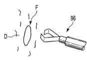
图1是表示可使用本发明第1~第11实施方式的内窥镜系统的各种器官(管路)的概略图。 FIG. 1 is a schematic diagram showing various organs (pipelines) to which endoscope systems according to the first to eleventh embodiments of the present invention can be used. the
图2是表示本发明第1实施方式的内窥镜系统的概略图。 Fig. 2 is a schematic diagram showing an endoscope system according to a first embodiment of the present invention. the
图3是表示第1实施方式的内窥镜系统的超声波内窥镜的插入部的前端部的概略立体图。 3 is a schematic perspective view showing the distal end portion of the insertion portion of the ultrasonic endoscope of the endoscope system according to the first embodiment. the
图4是表示第1实施方式的内窥镜系统中的套管(Overtube)的前端部的概略局部剖视图。 4 is a schematic partial cross-sectional view showing a distal end portion of an overtube in the endoscope system according to the first embodiment. the
图5是表示自第1实施方式的内窥镜系统中的套管的内管分离出线圈的状态的概略立体图。 5 is a schematic perspective view showing a state in which a coil is separated from the inner tube of the cannula in the endoscope system according to the first embodiment. the
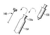
图6是表示第1实施方式的内窥镜系统中的T型杆留置器具的概略图。 6 is a schematic diagram showing a T-bar indwelling device in the endoscope system according to the first embodiment. the
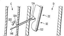
图7是表示第1实施方式的内窥镜系统中的T型杆留置器具的针构造及电手术刀构造的线状构件及芯部的概略立体图。 7 is a schematic perspective view showing the needle structure of the T-bar indwelling device and the linear member and the core of the electric scalpel structure in the endoscope system according to the first embodiment. the
图8是表示第1实施方式的内窥镜系统中的T型杆留置器具的电手术刀构造的线状构件、杆及芯部的概略立体图。 8 is a schematic perspective view showing a linear member, a rod, and a core of the electric scalpel structure of the T-bar indwelling device in the endoscope system according to the first embodiment. the
图9是表示将电手术刀构造组装在第1实施方式的内窥镜系统中的T型杆留置器具的针构造中的状态的概略剖视图。 9 is a schematic cross-sectional view showing a state where the electric scalpel structure is incorporated into the needle structure of the T-bar indwelling device in the endoscope system according to the first embodiment. the
图10是表示在使用第1实施方式的内窥镜系统,并用T型杆留置器具的针构造的针管从十二指肠(第1管腔)向总胆管(第2管腔)形成了穿孔之后,向总胆管内部排出了杆的状态的概略图。 Fig. 10 shows that the endoscopic system of the first embodiment is used, and the needle tube of the needle structure of the T-bar indwelling device is used to form a perforation from the duodenum (first lumen) to the common bile duct (second lumen) Thereafter, a schematic diagram of a state in which the rod is discharged into the common bile duct. the
图11是表示使用第1实施方式的内窥镜系统并以配置在总胆管中的T型杆留置器具的杆推压总胆管的内壁,而使总胆管靠近十二指肠的状态的概略图。 11 is a schematic diagram showing a state in which the common bile duct is brought close to the duodenum by pressing the inner wall of the common bile duct with the rod of the T-shaped bar indwelling device arranged in the common bile duct using the endoscope system according to the first embodiment; . the
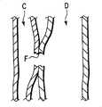
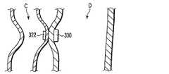
图12是表示在使用第1实施方式的内窥镜系统使总胆管靠近十二指肠之后,使套管的线圈贯穿于十二指肠及总胆管的状态的概略图。 12 is a schematic diagram showing a state in which the coil of the cannula is inserted through the duodenum and the common bile duct after the common bile duct is brought close to the duodenum using the endoscope system according to the first embodiment. the
图13是表示在使用第1实施方式的内窥镜系统使套管的线圈贯穿于十二指肠及总胆管之后,使线圈自套管的内管脱离的状态的概略图。 13 is a schematic diagram showing a state in which the coil of the cannula is detached from the inner tube of the cannula after the coil of the cannula is penetrated through the duodenum and the common bile duct using the endoscope system according to the first embodiment. the
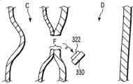
图14是表示使用第1实施方式的内窥镜系统向T型杆留置器具的杆通电而在线圈的内侧形成了瘘孔的状态的概略图。 FIG. 14 is a schematic diagram showing a state in which a fistula is formed inside the coil by energizing the rod of the T-shaped rod indwelling device using the endoscope system according to the first embodiment. the
图15是表示在使用第1实施方式的内窥镜系统形成了瘘孔之后,自瘘孔向总胆管内导入取石篮型钳子而用取石篮部保持 结石的状态的概略图。 Fig. 15 shows that after the fistula is formed using the endoscope system of the first embodiment, the stone basket type forceps are introduced from the fistula into the common bile duct and held by the stone basket.A schematic diagram of the state of the stone. the
图16是表示在使用第1实施方式的内窥镜系统形成了瘘孔之后,要用夹具将已不需要的瘘孔关闭的状态的概略图。 Fig. 16 is a schematic view showing a state where an unnecessary fistula is to be closed with a clip after the fistula is formed using the endoscope system according to the first embodiment. the
图17是表示在使用第1实施方式的内窥镜系统形成了瘘孔之后,用夹具将不需要的瘘孔关闭了的状态的概略图。 17 is a schematic view showing a state in which unnecessary fistulas are closed with clips after the fistulas are formed using the endoscope system according to the first embodiment. the
图18是表示使用第1实施方式的内窥镜系统使胃和小肠的空肠之间吻合了的状态的概略图。 18 is a schematic diagram showing a state in which the stomach and the jejunum of the small intestine are anastomosed using the endoscope system according to the first embodiment. the
图19是表示本发明第2实施方式的内窥镜系统的概略图。 Fig. 19 is a schematic diagram showing an endoscope system according to a second embodiment of the present invention. the
图20是表示第2实施方式的内窥镜系统中的内窥镜的插入部的前端部的概略图。 FIG. 20 is a schematic view showing the distal end portion of the insertion portion of the endoscope in the endoscope system according to the second embodiment. the
图21是表示将球囊配置在第2实施方式的内窥镜系统中的内窥镜的插入部的前端部,并使该球囊膨胀了的状态的概略剖视图。 21 is a schematic cross-sectional view showing a state in which a balloon is arranged at the distal end portion of the insertion portion of the endoscope in the endoscope system according to the second embodiment and the balloon is inflated. the
图22是表示第2实施方式的内窥镜系统中的超声波观察用穿刺针的概略图。 22 is a schematic diagram showing a puncture needle for ultrasonic observation in the endoscope system according to the second embodiment. the
图23是表示可相对于第2实施方式的内窥镜系统中的超声波观察用穿刺针的操作部的基端部装卸管心针和注射器的情况的概略图。 23 is a schematic diagram showing how a stylet and a syringe can be attached to and detached from the base end portion of the operation portion of the puncture needle for ultrasonic observation in the endoscope system according to the second embodiment. the
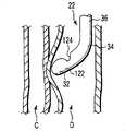
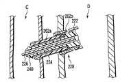
图24是表示在使用第2实施方式的内窥镜系统使超声波振子抵接在十二指肠的内壁上、并确认总胆管的位置之后,将超声波观察用穿刺针的针管配置在十二指肠与总胆管之间的状态的概略图。 Fig. 24 is a diagram showing that the needle tube of the puncture needle for ultrasonic observation is arranged in the duodenum after the ultrasonic vibrator is brought into contact with the inner wall of the duodenum and the position of the common bile duct is confirmed using the endoscope system according to the second embodiment. Schematic diagram of the state between the intestine and the common bile duct. the
图25是表示在使用第2实施方式的内窥镜系统将超声波观察用穿刺针的针管配置在十二指肠与总胆管之间之后,自针管的前端排出粘接剂的状态的概略图。 25 is a schematic diagram showing a state in which adhesive is discharged from the tip of the needle tube after the needle tube of the puncture needle for ultrasonic observation is placed between the duodenum and the common bile duct using the endoscope system according to the second embodiment. the
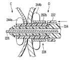
图26是表示在使用第2实施方式的内窥镜系统自超声波观察用穿刺针的针管的前端排出粘接剂之后,使内窥镜的插入部 的弯曲部弯曲,通过向总胆管一侧推压十二指肠使其移动、并与总胆管粘接的状态的概略图。 26 is a diagram showing that the insertion portion of the endoscope is moved after the adhesive is discharged from the tip of the needle tube of the puncture needle for ultrasonic observation using the endoscope system according to the second embodiment.A schematic diagram of the state where the bending part of is bent, moved by pushing the duodenum to the side of the common bile duct, and adhered to the common bile duct. the
图27是表示在使用第2实施方式的内窥镜系统使十二指肠与总胆管粘接之后,在其粘接着的部分形成了瘘孔的状态的概略图。 27 is a schematic view showing a state where a fistula is formed in the bonded portion after the duodenum and the common bile duct are bonded using the endoscope system according to the second embodiment. the
图28是表示在使用第2实施方式的内窥镜系统自超声波观察用穿刺针的针管的前端排出粘接剂之后,利用配设在内窥镜插入部的前端部的球囊的膨胀向总胆管一侧推压十二指肠而使其移动、并与总胆管粘接的状态的概略图。 Fig. 28 is a diagram showing that after the adhesive is discharged from the distal end of the needle tube of the puncture needle for ultrasonic observation using the endoscope system according to the second embodiment, the expansion of the balloon disposed at the distal end of the endoscope insertion part A schematic diagram of the state where one side of the bile duct pushes against the duodenum to move it and adheres to the common bile duct. the
图29是表示自本发明第3实施方式的内窥镜系统中的超声波内窥镜的插入部的前端部产生超声波处理用的超声波而使十二指肠与总胆管粘连的状态概略图。 29 is a schematic view showing a state in which the duodenum is adhered to the common bile duct by generating ultrasonic waves for ultrasonic treatment from the distal end of the insertion portion of the ultrasonic endoscope in the endoscope system according to the third embodiment of the present invention. the
图30是表示使超声波处理用能量处理器具自第3实施方式的内窥镜系统中的内窥镜的钳子通道的前端开口部突出,而用该能量处理器具使十二指肠与总胆管粘连的状态的概略图。 Fig. 30 shows that the energy treatment instrument for ultrasonic treatment is protruded from the front end opening of the forceps channel of the endoscope in the endoscope system according to the third embodiment, and the duodenum and the common bile duct are adhered by the energy treatment instrument An overview of the status of the . the
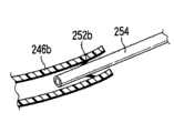
图31是表示本发明第4实施方式的内窥镜系统中的球囊留置器具及安装在该球囊留置器具前端部的带球囊的导管的概略纵剖视图。 31 is a schematic longitudinal sectional view showing a balloon indwelling device and a catheter with a balloon attached to the distal end of the balloon indwelling device in an endoscope system according to a fourth embodiment of the present invention. the
图32是表示自本发明第4实施方式的内窥镜系统中的球囊留置器具的前端部解除了带球囊的导管的卡合的状态的概略纵剖视图。 32 is a schematic longitudinal sectional view showing a state in which the engagement of the catheter with the balloon is released from the distal end portion of the balloon indwelling device in the endoscope system according to the fourth embodiment of the present invention. the
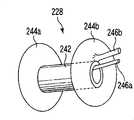
图33A及图33B是表示从图31中的箭头33方向观察将带球囊的导管安装在第4实施方式的内窥镜系统中的球囊留置器具中的状态的概略图。 33A and 33B are schematic diagrams showing a state in which the balloon-attached catheter is attached to the balloon indwelling device in the endoscope system according to the fourth embodiment, viewed from the direction of arrow 33 in FIG. 31 . the
图34是表示通过第4实施方式的内窥镜系统,使用于维持瘘孔的带球囊的导管中的球囊收缩的状态的概略纵剖视图。 34 is a schematic longitudinal sectional view showing a state in which a balloon in a catheter with a balloon for maintaining a fistula is deflated by the endoscope system according to the fourth embodiment. the
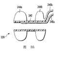
图35是表示通过第4实施方式的内窥镜系统,使用于维持 瘘孔的带球囊的导管中的球囊膨胀的状态的概略纵剖视图。 Fig. 35 shows the endoscope system of the fourth embodiment used to maintainA schematic longitudinal sectional view of a balloon-inflated catheter in a fistula. the
图36是表示在使用第4实施方式的内窥镜系统、并用球囊留置器具的针构件自十二指肠向总胆管形成了穿孔后,将带球囊的导管的前端侧的球囊配置在总胆管内部的状态的概略图。 Fig. 36 shows the arrangement of the balloon on the front end side of the catheter with the balloon after perforation is formed from the duodenum to the common bile duct with the needle member of the balloon indwelling device using the endoscope system according to the fourth embodiment; Schematic diagram of the condition inside the common bile duct. the
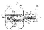
图37是表示在使用第4实施方式的内窥镜系统将带球囊的导管的前端侧的球囊配置在总胆管内部之后,使其前端侧的球囊膨胀了的状态的概略图。 37 is a schematic diagram showing a state in which the balloon on the distal side of the catheter with a balloon is inflated after the balloon on the distal side is placed inside the common bile duct using the endoscope system according to the fourth embodiment. the
图38是表示在使用第4实施方式的内窥镜系统使带球囊的导管的前端侧的球囊在总胆管内部膨胀之后,向手头侧拉近球囊留置器具,将基端侧的球囊配置在十二指肠内部并使其膨胀,从而使这两个球囊夹持着十二指肠与总胆管的壁面的状态的概略图。 38 shows that after the balloon on the distal side of the catheter with balloon is inflated inside the common bile duct using the endoscopic system of the fourth embodiment, the balloon indwelling device is pulled toward the hand side, and the balloon on the proximal side is moved. A schematic diagram of a state in which the balloons are placed inside the duodenum and inflated so that the walls of the duodenum and the common bile duct are sandwiched between the two balloons. the
图39是表示在用第4实施方式的内窥镜系统中的带球囊的导管的两球囊夹持十二指肠与总胆管的壁面之后,为了自球囊留置器具卸下带球囊的导管而从内套的前端拔下针构件的状态的概略图。 39 shows how to remove the balloon from the balloon indwelling device after clamping the walls of the duodenum and the common bile duct with the two balloons of the catheter with a balloon in the endoscope system according to the fourth embodiment. A schematic diagram of a state in which the needle member is pulled out from the front end of the inner sheath. the
图40是表示用第4实施方式的内窥镜系统中的带球囊的导管的两球囊夹持十二指肠与总胆管的壁面并将两球囊留置,直到两壁面粘连而使瘘孔成为稳定状态的状态的概略图。 Fig. 40 shows that the two balloons of the catheter with a balloon in the endoscopic system according to the fourth embodiment clamp the walls of the duodenum and the common bile duct and indwell the two balloons until the two walls are adhered to form a fistula. A schematic diagram of a state where a hole becomes a steady state. the
图41是表示在用第4实施方式的内窥镜系统中的带球囊的导管形成了瘘孔之后,除去了带球囊的导管的状态的概略图。 41 is a schematic view showing a state in which the balloon-attached catheter is removed after a fistula is formed by the balloon-attached catheter in the endoscopic system according to the fourth embodiment. the
图42A表示将向第4实施方式的内窥镜系统中的带球囊的导管的球囊中供给流体或从球囊中排出流体的管路留在十二指肠内的状态、是使图34及图35所示的带球囊的导管变形的概略纵剖视图。 42A shows a state in which a tube for supplying fluid to or discharging fluid from the balloon of the catheter with a balloon in the endoscope system according to the fourth embodiment is left in the duodenum. 34 and a schematic longitudinal sectional view of the deformation of the catheter with a balloon shown in FIG. 35 . the
图42B表示将向第4实施方式的内窥镜系统中的带球囊的导管的球囊中供给流体或从球囊中排出流体的管路留在十二指 肠内的状态、是使图34及图35所示的带球囊的导管变形的概略立体图。 Fig. 42B shows that the tube for supplying fluid to or discharging fluid from the balloon of the catheter with a balloon in the endoscopic system of the fourth embodiment is left in the twelve fingers.The state of the intestine is a schematic perspective view of deforming the catheter with a balloon shown in FIGS. 34 and 35 . the
图43是表示在第4实施方式的内窥镜系统中的、图42A及图42B所示的带球囊的导管的管路的基端部设有止回阀的状态的概略纵剖视图。 43 is a schematic longitudinal sectional view showing a state in which a check valve is provided at the base end portion of the tube of the catheter with a balloon shown in FIGS. 42A and 42B in the endoscope system according to the fourth embodiment. the
图44是表示向第4实施方式的内窥镜系统中的、图43所示的带球囊的导管的管路的基端部插入了细管的状态的概略局部纵剖视图。 44 is a schematic partial longitudinal sectional view showing a state in which a capillary tube is inserted into the proximal end portion of the conduit of the catheter with a balloon shown in FIG. 43 in the endoscope system according to the fourth embodiment. the
图45A是表示用图44所示的细管使第4实施方式的内窥镜系统中的、带球囊的导管的球囊膨胀之后,为了使球囊收缩而在管路的一部分设置了切口的状态的概略纵剖视图。 Fig. 45A shows that after the balloon of the catheter with a balloon in the endoscopic system according to the fourth embodiment is inflated with the thin tube shown in Fig. 44 , an incision is made in a part of the tubing in order to deflate the balloon; A schematic longitudinal sectional view of the state. the
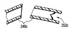
图45B是表示用图44所示的细管使第4实施方式的内窥镜系统中的、带球囊的导管的球囊膨胀之后,为了使球囊收缩而切断了管路的状态的概略纵剖视图。 45B is a schematic view showing a state in which the tube is cut to deflate the balloon after the balloon of the catheter with a balloon in the endoscope system according to the fourth embodiment is inflated using the thin tube shown in FIG. 44 Longitudinal view. the
图46是表示本发明第5实施方式的内窥镜系统中的球囊留置器具及安装在该球囊留置器具前端部的带球囊的导管的概略纵剖视图。 46 is a schematic longitudinal sectional view showing a balloon indwelling device and a catheter with a balloon attached to the distal end of the balloon indwelling device in an endoscope system according to a fifth embodiment of the present invention. the
图47A是表示第5实施方式的内窥镜系统中的带球囊的导管、特别是表示使前端侧的球囊与基端侧的球囊分隔开了的状态的概略纵剖视图。 47A is a schematic longitudinal sectional view showing a catheter with a balloon in the endoscope system according to the fifth embodiment, particularly showing a state in which the balloon on the distal side is separated from the balloon on the proximal side. the
图47B是表示第5实施方式的内窥镜系统中的带球囊的导管、特别是表示借助齿机构使前端侧的球囊与基端侧的球囊相接近的状态的概略纵剖视图。 47B is a schematic longitudinal sectional view showing a catheter with a balloon in the endoscope system according to the fifth embodiment, in particular, showing a state in which the balloon on the distal side is brought close to the balloon on the proximal side by the tooth mechanism. the
图48是表示在使用第5实施方式的内窥镜系统、并用球囊留置器具的针构件自十二指肠向总胆管形成了穿孔后,将带球囊的导管的前端侧的球囊配置在总胆管内部的状态的概略图。 Fig. 48 shows the arrangement of the balloon on the front end side of the catheter with the balloon after perforation is formed from the duodenum to the common bile duct with the needle member of the balloon indwelling device using the endoscope system according to the fifth embodiment; Schematic diagram of the condition inside the common bile duct. the
图49是表示在使用第5实施方式的内窥镜系统将带球囊的 导管的前端侧的球囊配置在总胆管内部之后,使该前端侧的球囊膨胀了的状态的概略图。 Fig. 49 shows that the endoscopic system with the balloon is used in the fifth embodiment.A schematic diagram of a state in which the balloon on the distal end side of the catheter is inflated after it is placed inside the common bile duct. the
图50是表示在使用第5实施方式的内窥镜系统使带球囊的导管的前端侧的球囊在总胆管内部膨胀之后,向手头侧拉近球囊留置器具,将基端侧的球囊配置在十二指肠内部并使其膨胀了的状态的概略图。 50 shows that after the balloon on the distal side of the catheter with balloon is inflated inside the common bile duct using the endoscopic system of the fifth embodiment, the balloon indwelling device is pulled toward the hand side, and the balloon on the proximal side is moved. A schematic diagram of a state in which the sac is placed inside the duodenum and inflated. the
图51是表示在使用第5实施方式的内窥镜系统使带球囊的导管的两球囊膨胀了之后,使基端侧的球囊移动而靠近前端侧的球囊,从而用两球囊夹持着十二指肠与总胆管的壁面的状态的概略图。 51 is a diagram showing that after the two balloons of the catheter with balloon are inflated using the endoscope system according to the fifth embodiment, the balloon on the proximal side is moved to approach the balloon on the distal side, so that the two balloons A schematic diagram of the state of the wall sandwiching the duodenum and the common bile duct. the
图52是表示第6实施方式的内窥镜系统中的带球囊的导管的概略纵剖视图。 Fig. 52 is a schematic longitudinal sectional view showing a catheter with a balloon in the endoscope system according to the sixth embodiment. the
图53是用表示第6实施方式的内窥镜系统中的带球囊的导管的前端侧的球囊及基端侧的球囊夹持十二指肠与总胆管的壁面,并在用配设在它们之间的小型球囊扩大瘘孔孔径状态下维持着瘘孔的状态的概略纵剖视图。 Fig. 53 shows the endoscopic system of the sixth embodiment with the balloon on the distal side and the balloon on the proximal side of the catheter with a balloon clamping the walls of the duodenum and the common bile duct, and using the A schematic longitudinal sectional view of a state in which the fistula is maintained while the small balloon installed between them enlarges the diameter of the fistula. the
图54A是表示在本发明第7实施方式的内窥镜系统中的超声波观察用穿刺针的前端部的针管中配置有磁体的状态的概略纵剖视图。 54A is a schematic longitudinal sectional view showing a state in which a magnet is arranged in the needle tube at the distal end of the puncture needle for ultrasonic observation in the endoscope system according to the seventh embodiment of the present invention. the
图54B是表示第7实施方式的内窥镜系统中的超声波观察用穿刺针的前端部的概略立体图。 54B is a schematic perspective view showing the distal end portion of the puncture needle for ultrasonic observation in the endoscope system according to the seventh embodiment. the
图55是表示自第7实施方式的内窥镜系统中的超声波观察用穿刺针的前端部的针管的侧孔排出磁体的状态概略纵剖视图。 55 is a schematic longitudinal sectional view showing a state in which a magnet is ejected from the side hole of the needle tube at the distal end of the puncture needle for ultrasonic observation in the endoscope system according to the seventh embodiment. the
图56是表示在使用第7实施方式的内窥镜系统、并用超声波观察用穿刺针的针管自十二指肠向总胆管形成了穿孔后,将磁体自针管的侧孔排出到总胆管内部的状态的概略图。Fig. 56 is a diagram showing that the magnet is discharged from the side hole of the needle tube into the common bile duct after the needle tube of the puncture needle for ultrasonic observation is used to perforate the common bile duct from the duodenum using the endoscope system according to the seventh embodiment. An overview of the state.
图57是表示在使用第7实施方式的内窥镜系统将磁体(第1磁体)配置在总胆管内部之后,用内窥镜将尺寸大于配置在总胆管内部的磁体尺寸的磁体(第2磁体)配置在十二指肠内的状态的概略图。 57 shows that after the magnet (first magnet) is placed inside the common bile duct using the endoscope system of the seventh embodiment, the magnet (second magnet) whose size is larger than that of the magnet placed inside the common bile duct is placed with an endoscope. ) is a schematic diagram of a state where it is arranged in the duodenum. the
图58是表示使用第7实施方式的内窥镜系统,使配置在总胆管内部的第1磁体与配置在十二指肠内部的第2磁体的吸引力互相作用,从而使他们隔着总胆管及十二指肠的壁面磁力吸引到一起的状态的概略图。 Fig. 58 shows that the endoscope system according to the seventh embodiment is used, and the attractive force of the first magnet arranged inside the common bile duct and the second magnet arranged inside the duodenum interact with each other so that they separate the common bile duct A schematic diagram of the state where the walls of the duodenum and the duodenum are magnetically attracted together. the
图59是表示使用第7实施方式的内窥镜系统,使被隔着总胆管及十二指肠的壁面磁力吸引到一起的第1及第2磁体压迫的部分的组织因缺血而坏死,从而形成了瘘孔的状态的概略图。 Fig. 59 shows that the tissue of the portion compressed by the first and second magnets magnetically attracted together across the common bile duct and the wall surface of the duodenum is necrotic due to ischemia using the endoscope system according to the seventh embodiment, Thus, a schematic diagram of the state of the fistula hole is formed. the
图60是表示本发明第8实施方式的内窥镜系统的概略图。 Fig. 60 is a schematic diagram showing an endoscope system according to an eighth embodiment of the present invention. the
图61是表示第8实施方式的内窥镜系统的磁体组件留置器具的概略局部剖视图。 Fig. 61 is a schematic partial cross-sectional view showing a magnet unit indwelling device of an endoscope system according to an eighth embodiment. the
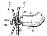
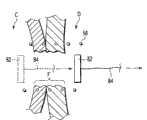
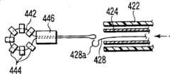
图62A是表示使用第8实施方式的内窥镜系统中的磁体组件留置器具留置的磁体组件、特别是表示磁体组件被配置在磁体组件留置器具中时的状态的概略图。 62A is a schematic diagram showing a magnet unit indwelled using the magnet unit indwelling tool in the endoscope system according to the eighth embodiment, particularly showing a state when the magnet unit is placed in the magnet unit indwelling tool. the
图62B是表示使用第8实施方式的内窥镜系统中的磁体组件留置器具留置的磁体组件、特别是表示磁体组件被配置在预定的管腔内时的状态的概略图。 62B is a schematic diagram showing a magnet unit indwelled using the magnet unit indwelling tool in the endoscope system according to the eighth embodiment, particularly showing a state when the magnet unit is arranged in a predetermined lumen. the
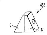
图63A及图63B是表示第8实施方式的内窥镜系统中的磁体组件所使用的磁体的概略立体图。 63A and 63B are schematic perspective views showing magnets used in the magnet unit in the endoscope system according to the eighth embodiment. the
图64A是表示第8实施方式的内窥镜系统中的磁体组件所使用的磁体的概略图。 64A is a schematic diagram showing magnets used in the magnet unit in the endoscope system according to the eighth embodiment. the
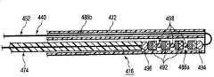
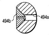
图64B是表示通过使第8实施方式的内窥镜系统中的磁体组件所使用的各磁体的端面具有鼓出,可在由线状构件维持着磁体间相互连结的状态下使磁体相互向适当的方向弯曲的状态 的概略图。 64B shows that by making the end faces of the magnets used in the magnet assembly of the endoscope system according to the eighth embodiment bulge, the magnets can be properly aligned with each other while maintaining the connection between the magnets by the linear member. The state of bending in the direction ofA schematic diagram of . the
图65是表示本发明第8实施方式的内窥镜系统中的磁体组件所使用的磁体的内周侧弦或圆弧(圆周)短于外周侧弦或圆弧(圆周),使得磁体在相互磁力吸引到一起时成为圆环状的状态的概略图。 65 shows that the inner chord or arc (circle) of the magnet used in the magnet assembly in the endoscope system according to the eighth embodiment of the present invention is shorter than the outer chord or arc (circle), so that the magnets are mutually A schematic diagram of the state of a ring shape when they are magnetically attracted together. the
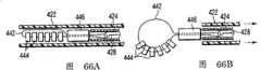
图66A是表示将第8实施方式的内窥镜系统中的磁体配置在磁体组件留置器具的壳的内侧的状态的概略局部剖视图。 66A is a schematic partial sectional view showing a state in which the magnet in the endoscope system according to the eighth embodiment is arranged inside the case of the magnet assembly indwelling device. the
图66B是表示使第8实施方式的内窥镜系统中的磁体组件的线状构件的前端及止挡件自磁体组件留置器具的壳的前端向外伸出的状态的概略局部剖视图。 66B is a schematic partial cross-sectional view showing a state in which the front end of the linear member and the stopper of the magnet unit protrude from the front end of the housing of the magnet unit indwelling device in the endoscope system according to the eighth embodiment. the
图66C是表示由第8实施方式的内窥镜系统中的磁体组件留置器具使磁体组件的止挡件向前方相对移动,而使线状构件的前端侧的环收缩了的状态的概略局部剖视图。 66C is a schematic partial cross-sectional view showing a state in which the ring on the front end side of the linear member is contracted by relatively moving the stopper of the magnet unit forward by the magnet unit indwelling device in the endoscope system according to the eighth embodiment; . the
图66D是表示第8实施方式的内窥镜系统中的磁体组件自磁体组件留置器具分离出来的状态的概略局部剖视图。 66D is a schematic partial cross-sectional view showing a state where the magnet unit is separated from the magnet unit indwelling tool in the endoscope system according to the eighth embodiment. the
图67是表示使用第8实施方式的内窥镜系统将磁体组件留置器具的壳的前端自十二指肠配置在总胆管内部的状态的概略图。 67 is a schematic diagram showing a state in which the distal end of the housing of the magnet assembly indwelling device is placed inside the common bile duct from the duodenum using the endoscope system according to the eighth embodiment. the
图68是表示使用第8实施方式的内窥镜系统中的磁体组件留置器具将磁体组件(第1磁体)配置在总胆管内部的状态的概略图。 68 is a schematic diagram showing a state in which a magnet unit (first magnet) is arranged inside a common bile duct using the magnet unit indwelling tool in the endoscope system according to the eighth embodiment. the
图69是表示使用第8实施方式的内窥镜系统,使配置在总胆管内部的第1磁体与配置在十二指肠内部的第2磁体的吸引力互相作用,从而使它们隔着总胆管及十二指肠的壁面磁力吸引到一起的状态的概略图。 Fig. 69 shows that the endoscope system according to the eighth embodiment is used, and the attractive force of the first magnet arranged inside the common bile duct and the second magnet arranged inside the duodenum interact with each other so that they are separated from each other through the common bile duct A schematic diagram of the state where the walls of the duodenum and the duodenum are magnetically attracted together. the
图70是表示使用第8实施方式的内窥镜系统配置在总胆管内部的第1磁体呈圆环状、配置在十二指肠内部的第2磁体呈圆 环状时,在它们的同心轴线的位置形成穿孔,从而形成瘘孔的状态的概略图。 70 shows that the first magnet arranged inside the common bile duct is in the shape of a ring and the second magnet arranged inside the duodenum is in the shape of a circle using the endoscope system of the eighth embodiment.In the case of rings, a perforation is formed at the position of their concentric axes to form a schematic diagram of the state of the fistula. the
图71是表示使用第8实施方式的内窥镜系统配置在总胆管内部的磁体组件的一个例子的概略图。 Fig. 71 is a schematic diagram showing an example of a magnet assembly disposed inside a common bile duct using the endoscope system according to the eighth embodiment. the
图72A是表示使用第8实施方式的内窥镜系统配置在总胆管内部的磁体组件的一个例子的概略图。 Fig. 72A is a schematic diagram showing an example of a magnet assembly disposed inside the common bile duct using the endoscope system of the eighth embodiment. the
图72B是表示将使用第8实施方式的内窥镜系统配置在总胆管内部的图72A所示的磁体组件的磁体磁力吸引到一起而成为大致圆环状的状态的概略图。 72B is a schematic diagram showing a state in which the magnets of the magnet assembly shown in FIG. 72A arranged inside the common bile duct are magnetically attracted together to form a substantially annular shape using the endoscope system according to the eighth embodiment. the
图72C是表示将使用第8实施方式的内窥镜系统配置在总胆管内部的图72A所示的磁体组件的磁体磁力吸引到一起而成为大致圆环状的状态的概略图。 72C is a schematic diagram showing a state in which the magnets of the magnet assembly shown in FIG. 72A arranged inside the common bile duct are magnetically attracted together to form a substantially annular shape using the endoscope system according to the eighth embodiment. the
图73A是表示第8实施方式的内窥镜系统中的磁体组件所使用的磁体的概略图。 73A is a schematic diagram showing magnets used in the magnet unit in the endoscope system according to the eighth embodiment. the
图73B是表示第8实施方式的内窥镜系统中的磁体组件所使用的非磁性体的概略图。 73B is a schematic diagram showing a non-magnetic body used in a magnet unit in the endoscope system according to the eighth embodiment. the
图73C是表示将第8实施方式的内窥镜系统中的磁体组件所使用的图73A所示的磁体排列成C字状、将图73B所示的非磁性体配置在磁体之间的状态的概略图。 73C is a diagram showing a state in which the magnets shown in FIG. 73A used in the magnet assembly of the endoscope system according to the eighth embodiment are arranged in a C-shape and the non-magnetic body shown in FIG. 73B is arranged between the magnets. sketch map. the
图73D是表示第8实施方式的内窥镜系统中的磁体组件所使用的图73C所示的磁体组件的磁力状态的概略图。 FIG. 73D is a schematic diagram showing a magnetic force state of the magnet unit shown in FIG. 73C used in the magnet unit in the endoscope system according to the eighth embodiment. the
图74A是表示将第8实施方式的内窥镜系统中的磁体组件所使用的2个磁体连接在一起的状态的概略图。 74A is a schematic diagram showing a state where two magnets used in the magnet unit in the endoscope system according to the eighth embodiment are connected together. the
图74B是表示第8实施方式的内窥镜系统中的磁体组件所使用的图74A所示的磁体组件的磁力状态的概略图。 Fig. 74B is a schematic diagram showing a magnetic state of the magnet unit shown in Fig. 74A used in the magnet unit in the endoscope system according to the eighth embodiment. the
图75是表示要将第8实施方式的内窥镜系统中的磁体组件留置器具的壳的前端自十二指肠的乳头状突起配置在总胆管内 部,将磁体组件配置在总胆管内部的状态的概略图。 Fig. 75 shows that the front end of the shell of the magnet assembly indwelling device in the endoscope system according to the eighth embodiment is to be placed in the common bile duct from the papillae of the duodenumPart, a schematic diagram of the state where the magnet assembly is arranged inside the common bile duct. the
图76是表示使第8实施方式的内窥镜系统中的磁体组件通过经皮经肝胆管导液装置所使用的管,而将该磁体组件配置在总胆管内部的状态的概略图。 76 is a schematic diagram showing a state in which the magnet assembly in the endoscopic system according to the eighth embodiment is arranged inside the common bile duct by passing the magnet assembly through the tube used in the percutaneous transhepatic bile duct catheterization device. the
图77A是表示第9实施方式的内窥镜系统中的磁体组件留置器具的概略局部剖视图。 77A is a schematic partial cross-sectional view showing a magnet unit indwelling tool in the endoscope system according to the ninth embodiment. the
图77B是表示从图77A中的箭头77B方向观察第9实施方式的内窥镜系统的磁体组件留置器具的壳的概略图。 77B is a schematic view showing the case of the magnet unit indwelling tool of the endoscope system according to the ninth embodiment viewed from the direction of
图78是表示在第9实施方式的内窥镜系统中的磁体组件留置器具中配置有磁体组件的状态的概略剖视图。 78 is a schematic cross-sectional view showing a state in which a magnet assembly is arranged in a magnet assembly indwelling device in an endoscope system according to a ninth embodiment. the
图79是表示第9实施方式的内窥镜系统中的磁体组件所使用的磁体的概略纵剖视图。 79 is a schematic longitudinal sectional view showing a magnet used in a magnet unit in the endoscope system according to the ninth embodiment. the
图80A是表示第9实施方式的内窥镜系统中的磁体组件所使用的前端止挡件的概略纵剖视图。 80A is a schematic longitudinal sectional view showing a distal end stopper used in the magnet unit in the endoscope system according to the ninth embodiment. the
图80B是表示第9实施方式的内窥镜系统中的磁体组件所使用的前端止挡件与被施加较大力时卡合在前端止挡件上的楔状构件卡合着的状态的概略纵剖视图。 80B is a schematic longitudinal sectional view showing a state in which the end stopper used in the magnet unit in the endoscope system according to the ninth embodiment engages with the wedge-shaped member that engages with the end stopper when a large force is applied thereto; . the
图81A是表示第9实施方式的内窥镜系统中的磁体组件所使用的基端止挡件的概略纵剖视图。 81A is a schematic longitudinal sectional view showing a proximal end stopper used in the magnet unit in the endoscope system according to the ninth embodiment. the
图81B是表示第9实施方式的内窥镜系统中的磁体组件所使用的基端止挡件与被施加较大力时卡合在基端止挡件上的楔状构件卡合着的状态的概略纵剖视图。 81B is a schematic view showing a state where the proximal stopper used in the magnet unit in the endoscope system according to the ninth embodiment engages with the wedge-shaped member that engages with the proximal stopper when a large force is applied thereto; Longitudinal view. the
图82是表示第9实施方式的内窥镜系统中的磁体组件所使用的隔离件的概略纵剖视图。 Fig. 82 is a schematic longitudinal sectional view showing a spacer used in the magnet unit in the endoscope system according to the ninth embodiment. the
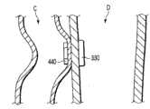
图83A是表示在第9实施方式的内窥镜系统中的磁体组件留置器具中配设有磁体组件的状态下,将壳的前端配置在总胆管内部的状态的概略剖视图。83A is a schematic cross-sectional view showing a state in which the distal end of the case is placed inside the common bile duct in a state where the magnet unit is placed in the magnet unit indwelling tool in the endoscope system according to the ninth embodiment.
图83B是表示在第9实施方式的内窥镜系统中,在使磁体组件的前端止挡件相对于磁体组件留置器具中配设有磁体组件的壳的前端突出而将其配置在总胆管内部之后,向手头侧拉第2腔管内的线状构件的状态的概略剖视图。 FIG. 83B shows that in the endoscope system according to the ninth embodiment, the front end stopper of the magnet unit protrudes from the front end of the housing on which the magnet unit is arranged in the magnet unit indwelling device and is arranged inside the common bile duct Thereafter, a schematic cross-sectional view of a state where the linear member in the second lumen is pulled toward the immediate side. the
图83C是表示在第9实施方式的内窥镜系统中,缩短配置在磁体组件留置器具中的磁体组件的基端止挡件与前端止挡件之间的距离,而使隔离件要进入磁体的通孔的锥状缘部的状态的概略图。 83C shows that in the endoscope system according to the ninth embodiment, the distance between the base end stopper and the front end stopper of the magnet assembly arranged in the magnet assembly indwelling device is shortened so that the spacer is about to enter the magnet. A schematic diagram of the state of the tapered edge of the through-hole. the
图83D是表示在第9实施方式的内窥镜系统中,通过使隔离件进入到配置在磁体组件留置器具中的磁体组件的磁体的通孔中,使相邻的磁体相互磁力吸附的状态的概略图。 83D is a diagram showing a state in which adjacent magnets are magnetically attracted to each other by inserting a spacer into the through hole of the magnet of the magnet assembly disposed in the magnet assembly indwelling device in the endoscope system according to the ninth embodiment; sketch map. the
图83E是表示在第9实施方式的内窥镜系统中,使配置在磁体组件留置器具中的磁体组件的相邻的磁体相互磁力吸附,而使它们成为与具有S极及N极的较大的磁体相当的状态的概略图。 83E shows that in the endoscope system according to the ninth embodiment, the adjacent magnets of the magnet assembly arranged in the magnet assembly indwelling device are magnetically attracted to each other, so that they become larger than each other with S poles and N poles. Schematic diagram of the equivalent state of the magnet. the
图83F是表示在第9实施方式的内窥镜系统中,向壳的前端侧推入推动器,而使配置在磁体组件留置器具中的磁体组件自壳的前端向外侧伸出的状态的概略图。 83F is a schematic view showing a state in which the pusher is pushed toward the front end side of the housing to make the magnet assembly arranged in the magnet assembly indwelling device protrude outward from the front end of the housing in the endoscope system according to the ninth embodiment; picture. the
图83G是表示在第9实施方式的内窥镜系统中,使推动器及壳自配置在磁体组件留置器具中的磁体组件分离,而将磁体组件配置在总胆管内部的状态的概略图。 83G is a schematic diagram showing a state in which the pusher and the case are separated from the magnet unit arranged in the magnet unit indwelling tool and the magnet unit is placed inside the common bile duct in the endoscope system according to the ninth embodiment. the
图84是表示本发明第10实施方式的内窥镜系统中的磁体组件留置器具的概略局部剖视图。 Fig. 84 is a schematic partial cross-sectional view showing the magnet unit indwelling tool in the endoscope system according to the tenth embodiment of the present invention. the
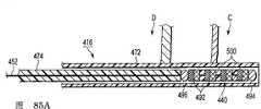
图85A是表示在第10实施方式的内窥镜系统中,在磁体组件留置器具中配设有磁体组件的状态下,将磁体组件留置器具的壳的前端配置在总胆管内部的状态的概略剖视图。 85A is a schematic cross-sectional view showing a state in which the front end of the housing of the magnet assembly indwelling device is placed inside the common bile duct in the state where the magnet assembly is disposed in the magnet assembly indwelling device in the endoscope system according to the tenth embodiment; . the
图85B是表示在第10实施方式的内窥镜系统中,在磁体组 件留置器具中配设磁体组件的状态下用推动器推压基端止挡件时使磁体自壳的前端突出,并且使配置在磁体之间的具有生物适应性的隔离件脱落至总胆管内部的状态的概略剖视图。 Fig. 85B shows that in the endoscope system according to the tenth embodiment, in the magnet groupWhen the base end stopper is pushed with a pusher in the state where the magnet assembly is arranged in the component indwelling device, the magnet protrudes from the front end of the shell, and the biocompatible spacer arranged between the magnets falls off to the inside of the common bile duct A schematic cross-sectional view of the state. the
图85C是表示在第10实施方式的内窥镜系统中,在磁体组件留置器具中配设有磁体组件的状态下进一步用推动器推压基端止挡件时使磁体自壳的前端突出,并且使配置在磁体之间的具有生物适应性的隔离件脱落至总胆管内部的状态的概略剖视图。 85C shows that in the endoscope system according to the tenth embodiment, the magnet protrudes from the front end of the housing when the base end stopper is further pushed by the pusher in the state where the magnet assembly is arranged in the magnet assembly indwelling device, And it is a schematic cross-sectional view of a state in which the biocompatible spacer arranged between the magnets falls off to the inside of the common bile duct. the
图85D是表示在第10实施方式的内窥镜系统中,在磁体组件留置器具中配设有磁体组件的状态下进一步用推动器推压基端止挡件,而相对于磁体组件留置器具的壳的前端突出至基端止挡件的状态的概略剖视图。 Fig. 85D shows that in the endoscope system according to the tenth embodiment, the base end stopper is further pushed by the pusher in the state where the magnet assembly indwelling instrument is arranged, and the position of the magnet assembly indwelling instrument is relative to that of the magnet assembly indwelling instrument. A schematic sectional view of a state where the front end of the case protrudes to the base end stopper. the
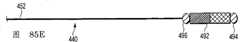
图85E是表示在第10实施方式的内窥镜系统中,使磁体组件相对于磁体组件留置器具的壳的前端突出至磁体组件的基端止挡件之后,将磁体组件配置在总胆管内部的状态的概略图。 FIG. 85E is a diagram showing that, in the endoscope system according to the tenth embodiment, the magnet assembly is arranged inside the common bile duct after the front end of the magnet assembly is protruded from the housing of the magnet assembly indwelling device to the base end stopper of the magnet assembly. An overview of the state. the
图86是表示本发明第11实施方式的内窥镜系统中的磁体组件留置器具的概略局部剖视图。 Fig. 86 is a schematic partial cross-sectional view showing the magnet unit indwelling device in the endoscope system according to the eleventh embodiment of the present invention. the
图87A是表示在第11实施方式的内窥镜系统中,在磁体组件留置器具中配设有磁体组件的状态下将壳的前端配置在总胆管内部的状态的概略剖视图。 87A is a schematic cross-sectional view showing a state in which the distal end of the case is placed inside the common bile duct in the state where the magnet unit is placed in the magnet unit indwelling tool in the endoscope system according to the eleventh embodiment. the
图87B是表示在第11实施方式的内窥镜系统中,在磁体组件留置器具中配设有磁体组件的状态下进一步用推动器推压基端止挡件,而使磁体组件相对于磁体组件留置器具的壳的前端突出至基端止挡件,并且回收隔离件的状态的概略剖视图。 87B shows that in the endoscope system according to the eleventh embodiment, in the state where the magnet assembly is placed in the magnet assembly indwelling device, the base end stopper is further pushed by the pusher, so that the magnet assembly is positioned relative to the magnet assembly. A schematic sectional view of a state where the front end of the shell of the indwelling device protrudes to the base end stopper and the spacer is retracted. the
具体实施方式Detailed ways
包含在说明书中并构成说明书的一部分、且示出本发明的 实施例、附图与说明书一起用于解释本发明的原理。 contained in and constitute a part of the specification and which illustrate the present inventionEmbodiment, drawing and description are used to explain the principle of the present invention together. the
下面,参照附图说明用于实施本发明的最佳方式。 Hereinafter, the best mode for carrying out the present invention will be described with reference to the drawings. the
使用图1~图18说明第1实施方式。 The first embodiment will be described using FIGS. 1 to 18 . the
在图1中概略地示出了胃S、十二指肠D、小肠的空肠(以后主要简称为空肠)J、胆囊G、总胆管C等。而且,有时要在十二指肠(第1管腔)D和总胆管(第2管腔)C之间、胃(第1管腔)S和空肠(第2管腔)J之间等进行使各种器官(管腔)相互吻合而形成瘘孔的瘘孔形成手术。在此,主要说明为了使例如总胆管C内的胆汁流入到十二指肠D内,而在十二指肠D和总胆管C之间形成瘘孔的情况。 FIG. 1 schematically shows a stomach S, a duodenum D, a jejunum of the small intestine (hereinafter mainly simply referred to as jejunum) J, a gallbladder G, a common bile duct C, and the like. In addition, it is sometimes performed between the duodenum (1st lumen) D and the common bile duct (2nd lumen) C, between the stomach (1st lumen) S and the jejunum (2nd lumen) J, etc. Fistula formation surgery is performed by anastomosis of various organs (cavity) to form a fistula. Here, for example, a case where a fistula is formed between the duodenum D and the common bile duct C to allow bile in the common bile duct C to flow into the duodenum D will be mainly described. the
图2所示的内窥镜系统10具有超声波内窥镜12、套管14和T型杆留置器具16。T型杆留置器具16与超声波内窥镜12一同用于内窥镜。 The
超声波内窥镜12具有细长的插入部22、设在该插入部22基端部的操作部24和自操作部24延伸出的通用软线26。插入部22具有前端硬性部32、弯曲部34和挠管部36。通过转动操作部24的弯曲操作旋钮24a,可使弯曲部34向期望的方向弯曲。挠管部36可随着生物体管腔的形状弯曲。从插入部22到操作部24贯穿有钳子通道38(参照图3)。该钳子通道38的基端部设在操作部24上。在钳子通道38的基端侧的开口部(钳子口)配设有钳子拴38b。 The
如图3所示,在前端硬性部32的前端面配设有超声波观察用的电子凸起型超声波振子42、钳子通道38的前端开口部38a和光学观察用物镜44。虽未图示,但在前端硬性部32的前端面还配设有射出光学观察用光的照明透镜。 As shown in FIG. 3 , on the distal end surface of the distal
因此,超声波内窥镜12具有对被摄体进行超声波观察的超声波观察功能、和进行光学观察的光学观察功能。虽然可对被 摄体进行超声波观察的距离还取决于给与超声波振子42的频率,但该距离为距超声波振子42与生物体组织相接触的接触面例如20mm~70mm左右。 Therefore, the
超声波振子42、钳子通道38的前端开口部38a和物镜44在与插入部22的轴线方向正交的方向上配设在一条直线(一列)上。特别是,钳子通道38的前端开口部38a配设在前端硬性部32(插入部22)的大致中心轴线上,且超声波振子42和物镜44配设在相对于钳子通道38的前端开口部38a对称的位置。即,前端开口部38a配设在物镜44和超声波振子42之间的中央部。 The
如图4所示,套管14形成为双层构造。套管14具有外管52、内管54和线圈(线圈针)56。线圈56优选具有绝缘性,进一步讲,优选由生物体吸收性材料形成。另外,线圈56也可以由形状记忆材料形成。线圈56配设在内管54的前端部。在内管54的前端部的内周面形成有螺旋状沟54a。因此,该线圈56凭借助摩擦以可相对于内管54前端部的内周面的螺旋状沟54a装卸地与该螺旋状沟54a卡合(螺纹结合)。 As shown in FIG. 4, the
如图5所示,为了防止线圈56卡合在内管54的螺旋状沟54a中时在内管54上形成穿孔,该线圈56的基端被倒圆。另一方面,自内管54的前端突出的线圈56的前端形成为针状。 As shown in FIG. 5 , in order to prevent the
如图4所示,外管52可相对于内管54移动,在内窥镜12的插入部22插入到体腔内时可包覆内管54前端的线圈56。 As shown in FIG. 4 , the
如图6所示,T型杆留置器具16具有外套(主体)62、管状的针构造64和电手术刀构造66。针构造64可在外套62的内腔中移动。并且,电手术刀构造66可在针构造64的内腔中移动。由于需要贯穿内窥镜12的钳子通道38,因此外套62的外径稍小于钳子通道38的口径,外套62、针构造64及电手术刀构造66形成为长度大于钳子通道38的长度。As shown in FIG. 6 , the T-
如图6及图7所示,针构造64具有针管72、软性管(内套)74和针致动件76。针管72固定在软性管74的前端,针致动件76固定在软性管74的基端。 As shown in FIGS. 6 and 7 , the
如图6及图8所示,电手术刀构造66具有杆状的棒(比线状构件84大的构件(鼓出构件))82、线状构件84、芯部86和芯致动件88。棒82固定在线状构件84的前端,芯部86的前端固定在线状构件84的基端。特别是,线状构件84的前端固定在棒82的中央。因此,当拉线状构件84时,棒82与线状构件84的关系成为大致T字形。另外,棒82的长度形成为小于上述线圈56的内径。这些芯部86、线状构件84及棒82具有导电性。并且,作为电极连接器的芯致动件88固定在芯部86的基端部。因此,可使高频电流流入芯致动件88、芯部86、线状构件84及棒82中。 As shown in FIGS. 6 and 8 , the
而且,如图9所示,在使用T型杆留置器具16之前,棒82及线状构件84以被夹持在针管72内部的状态固定着。芯部86被用作棒82的推动器。因此,当使芯致动件88向前移动时,芯部86移动而将棒82从针管72的前端推出。 Furthermore, as shown in FIG. 9 , before the T-
另外,通过操作针致动件76,可使针构造64的针管72的前端在从外套62的前端突出的状态和被从外套62的前端拉入的状态之间移动。另外,若是在将棒82从针管72的前端推出之前,则电手术刀构造66与针构造64一同移动。 In addition, by operating the
接着,对本实施方式的内窥镜系统10的作用进行说明。 Next, the operation of the
如图2所示,对超声波内窥镜12的插入部22覆盖双层构造的套管14。而且,套管14是预先将内管54拉入到外管52中。此时,预先将卡合在内管54前端部上的线圈56的整体拉入到比外管52的前端更靠近基端侧的位置。在该状态下,将内窥镜12的插入部22及套管14的前端经过口腔导入至十二指肠D中。 As shown in FIG. 2 , the
使超声波内窥镜12的超声波振子42顶到十二指肠D的内 壁。而且,用使超声波内窥镜12的超声波振子42振动而得到的超声波图像来确认总胆管C的位置。 Push the
预先将T型杆留置器具16的针管72拉入到比外套62的前端更靠近基端侧的位置。然后,使T型杆留置器具16的外套62自超声波内窥镜12的钳子通道38的钳子栓38b通过钳子通道38的前端开口部38a,而从内窥镜12的插入部22的前端突出。操作T型杆留置器具16的针致动件76,使针管72从外套62的前端突出。 The
然后,用针管72穿透十二指肠D的壁部,进一步穿透总胆管C的壁面。即,针管72的前端处于总胆管C的内部。在该状态下,使芯致动件88向前方侧移动。于是,如图10所示,利用芯部86将棒82从针管72的前端推出而使其落到总胆管C的内部。即,将棒82配设在总胆管C的内部。在该状态下,使针致动件76移动而将针管72的前端向外套62中拉入。因此,将针管72从总胆管C及十二指肠D的壁面拔出。 Then, the
在该状态下,将芯致动件88相对于外套62拉向手头侧。于是,固定在芯部86前端的线状构件84被拉向手头侧。因此,固定在线状构件84前端的棒82被拉向手头侧。于是,如图11所示,用棒82向十二指肠D一侧按压总胆管C的内壁,而使总胆管C的外壁紧贴在十二指肠D的外壁上。 In this state, the
在此,使套管14的外管52相对于内管54向基端侧移动。于是,线圈56从外管52露出。使内管54以覆盖着内窥镜12的插入部22的外周面的状态向规定的方向(第1方向)旋转。于是,如图12所示,从线圈56的针状前端开始穿透十二指肠D的壁面及总胆管C的壁面。若线圈56的前端到达了总胆管C的内部,则使内管54向与上述第1方向相反的第2方向旋转。于是,线圈56与内管54前端部内周面的螺旋状沟54a之间的卡合被解除。因 此,如图13所示,以使十二指肠D与总胆管C的外壁相互紧贴的状态留置线圈56。 Here, the
而且,将高频电源(未图示)电安装到T型杆留置器具16的芯致动件(连接器)88上。从高频电源向芯致动件88、线状构件84及棒82通入高频电流。因此,如图14所示,首先在与棒82接触着的总胆管C的壁面形成孔,接着在与总胆管C的壁面紧贴着的十二指肠D的壁面形成孔。即,在总胆管C和十二指肠D之间形成瘘孔F。 Furthermore, a high-frequency power supply (not shown) is electrically attached to the core actuator (connector) 88 of the T-
若线圈56是以生物体吸收性材料形成的,则会随着时间的推移而逐渐被生物体吸收,并最终消失。例如在线圈56消失时,由于总胆管C与十二指肠D粘连而形成瘘孔F。换言之,十二指肠D与总胆管C相吻合。因此,可以防止总胆管C的壁面与十二指肠D的壁面相分离而使胆汁漏至腹腔内,总胆管C内的胆汁会通过漏孔F流向十二指肠D一侧。 If the
另外,若线圈56具有绝缘性,则即使在施加高频电流时棒82与线圈56的接触也是安全的。另外,在用形状记忆材料形成线圈56时,利用形状记忆材料的特性,可在使该线圈56暴露于体温一段时间后使其形状向线圈56的卷绕状态变密的方向变化。此时,利用形状记忆材料的特性使总胆管C与十二指肠D贴得更紧,因此降低了胆汁漏至腹腔内的危险,可促进形成瘘孔F。 In addition, if the
接着,如图15所示,说明使用侧视型内窥镜90及取石篮型钳子92,利用自胆道(胆囊、胆囊管、肝内胆管、肝门部胆管、总胆管的总称)B向十二指肠D开设的瘘孔(旁路)F从十二指肠D一侧取出胆道B内的结石Co的技术。 Next, as shown in FIG. 15 , the use of a side-viewing
在该情况下,使取石篮型钳子92贯穿于内窥镜90的钳子通道(未图示)。然后,从瘘孔F向胆道B内插入取石篮型钳子92 的取石篮部94。用取石篮部94保持着结石Co而从瘘孔F中将其取出。而且,将该结石Co放出到十二指肠D中。或者,在用取石篮部94保持着该结石Co的状态下通过内窥镜12而将其回收。 In this case, the stone
如图16及图17所示,在这样除去了结石Co后不需要瘘孔F的情况下,可使用内窥镜,用夹具96从十二指肠D一侧封闭瘘孔F。若封闭瘘孔F时,则可以防止因肠液流入胆道B中而产生的胆管炎等病发症。而且,夹具96在经过一段时间后会自然地脱落到十二指肠D内。 As shown in FIGS. 16 and 17 , when the fistula F is unnecessary after removing the calculus Co in this way, the fistula F can be closed from the duodenum D side with a
如以上说明的那样,采用本实施方式可达到以下效果。 As described above, according to this embodiment, the following effects can be achieved. the
在将套管14的线圈56旋入生物体组织时,在将线圈56安装在内管54的螺旋状沟54a中的状态下,使内管54绕其轴线旋转,从而可以简单地进行操作。另外,在拆卸被旋入到生物体组织中的线圈56和内管54时,只需使内管54向反方向旋转即可简单地进行操作。因此,能以简单的操作使十二指肠D与总胆管C的壁面相互一体化。 When screwing the
超声波观察用超声波振子42、钳子通道38的前端开口部38a和光学观察用物镜44配设在一条直线上,且超声波振子42和物镜44配设在相对于钳子通道38的前端开口部38a大致对称的位置。因此,可以使超声波观察图像和光学观察图像的视点一致。因此,可以在对超声波观察图像和光学观察图像进行视觉对比时容易地确认T型杆留置器具16的棒82和线状构件84。 The
另外,由于将前端开口部38a配置在内窥镜12的插入部22的前端硬性部32的中心轴线的位置,因此可以用T型杆留置器具16的针管72在套管14的线圈56的中心附近进行穿孔。并且,在用T型杆留置器具16的棒82形成瘘孔时,可以容易地穿过线圈56的中心轴线(线圈56的内部)。 In addition, since the
可以使用内窥镜,用自十二指肠D一侧使十二指肠D的壁面 和总胆管C的壁面相靠近且连通的瘘孔F将两者连接起来。因此,因某种原因在总胆管C中产生了堵塞(狭窄)等时,可以简单地形成瘘孔F而向十二指肠D中排出总胆管C内的胆汁。 An endoscope can be used to make the wall of the duodenum D from the side of the duodenum DThe fistula F, which is close to and communicates with the wall of the common bile duct C, connects the two. Therefore, when blockage (stenosis) or the like occurs in the common bile duct C for some reason, the fistula F can be easily formed and the bile in the common bile duct C can be discharged into the duodenum D. the
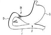
另外,在本实施方式中,对使十二指肠D与总胆管C相吻合的情况进行了说明,但也适合这种情况:如图18所示,在十二指肠D中存在狭窄部St并因该狭窄部St使食物难以通过时,通过与第1实施方式中说明的作用相同的作用,使胃S与空肠J相吻合。于是,由于可以使食物从胃S直接流入小肠的空肠J中,因此可以提高患者的QOL(生活品质)。 In addition, in this embodiment, the case where the duodenum D is anastomosed with the common bile duct C has been described, but it is also suitable for the case where there is a stricture in the duodenum D as shown in FIG. 18 When food is difficult to pass through St due to the narrow portion St , the stomach S and the jejunum J are brought together by the same operation as that described in the first embodiment. Then, since the food can be directly flowed from the stomach S into the jejunum J of the small intestine, the QOL (quality of life) of the patient can be improved.
下面,在第2~第11实施方式中对使十二指肠D与总胆管C之间相吻合的情况进行说明,但也可以用于使胃S与空肠J吻合。 Next, in the second to eleventh embodiments, the case of anastomosis between the duodenum D and the common bile duct C will be described, but it can also be used for anastomosis of the stomach S and jejunum J. the
接着,使用图19~图28说明第2实施方式。本实施方式为第1实施方式的变型例,对与第1实施方式中说明的构件相同的构件标注相同的附图标记,省略其详细说明。 Next, a second embodiment will be described using FIGS. 19 to 28 . This embodiment is a modified example of the first embodiment, and the same members as those described in the first embodiment are denoted by the same reference numerals, and detailed description thereof will be omitted. the
如图19所示,内窥镜系统10具有电子凸起型超声波内窥镜12和超声波观察用穿刺针116。在此虽未详细说明,但为了辅助向体腔内导入内窥镜12的插入部22,也适合使用套管(未图示)。 As shown in FIG. 19 , the
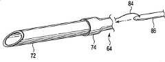
如图20所示,与第1实施方式相同,内窥镜12具有插入部22和操作部24。本实施方式所使用的内窥镜12的插入部22的前端硬性部32,在前端具有超声波振子122,在该超声波振子122的基端侧具有倾斜面124,在该倾斜面124上配设有前端开口部38a、物镜44及照明透镜(未图示)。因此,将该内窥镜12设为光学观察光学系、即物镜44及照明透镜自插入部22的轴线方向相分离的侧视型。 As shown in FIG. 20 , the
另外,如图20及图21所示,在内窥镜12的插入部22的前端 硬性部32上,在超声波振子122和倾斜面124之间形成有球囊安装沟126。图21所示,例如在与设有前端开口部38a、物镜44和照明透镜的倾斜面124一侧相反的一侧形成有具有开口的球囊管路132。通过向球囊管路132中注入水(液体),使固定在球囊安装沟126上的球囊134膨胀。通过向球囊管路132施加吸引力,可以将使球囊134膨胀过的水抽出,而使球囊134收缩。 In addition, as shown in FIGS. 20 and 21 , the distal end of the
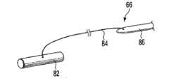
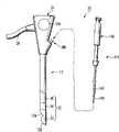
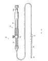
如图22所示,超声波观察用穿刺针116具有壳142、操作部144和例如不锈钢钢材制的针管146。壳142可插入到内窥镜12的钳子通道38中。操作部144配置在该壳142的基端部。针管146的前端利用操作部144相对于壳142的前端自由移动地贯穿至该壳142的前端。管心针148可自由插拔地配置在针管146的内部。 As shown in FIG. 22 , the
操作部144具有操作部主体152、用树脂构件形成的滑动件154、和制动器156;操作部主体152设在壳142的基端部;滑动件154相对于该操作部主体152自由滑动地设置在该操作部152上;制动器156设在操作部主体152上,用于限制滑动件154的可动范围。 The
滑动件154与针管146连结。因此,当使滑动件154相对于操作部主体152移动时,针管146相对于壳142移动。在该滑动件154的基端部配置有吸引接头154a。如图23所示,可相对于该吸引接头154a装卸注射器158和管心针148。在图22中,管心针148配设在滑动件154的基端部的吸引接头154a中。因此,通过使滑动件154相对于操作部主体152移动,可使针管146及管心针148一同移动。 The
由于该穿刺针116的针管146用于进行超声波观察,因此将穿刺针116插入到超声波内窥镜12的钳子通道38中。于是,在显示着目的部位的超声波观察图像上描画出了针管146的超声 波图像。之后,医生把持着滑动件154,使该滑动件154快速地向制动器156移动。于是,管心针148及针管146的前端可靠地在目的部位上进行穿刺。 Since the
接着,对本实施方式的内窥镜系统10的作用进行说明。 Next, the operation of the
如第1实施方式中说明的那样,将超声波内窥镜12的插入部22的前端部引导至十二指肠D。而且,通过超声波图像确认总胆管C的位置。 The distal end portion of the
如图24所示,使穿刺针116的壳142的前端从钳子通道38的前端开口部38a突出,而使其穿透总胆管C附近的十二指肠D的壁部。而且,如图22及图23所示,从穿刺针116的操作部144的滑动件154的基端部的吸引接头154a中卸下管心针148。代替管心针148,将加入了粘接剂的注射器158安装在滑动件154的基端部的吸引接头154a中。接着,一边用超声波图像进行观察,一边如图25所示那样从针管146的前端排出粘接剂Ah。另外,粘接剂Ah例如可使用氰基丙烯酸酯系的粘接剂、散布后述第1液散布后第2液的粘接剂、纤维蛋白糊(2液混合型)等的医疗用粘接剂。上述第1液散布后第2液是在明胶中散布了间苯二酚的情况等而制成的。另外,粘接剂Ah适宜具有速干性。 As shown in FIG. 24 , the tip of the
然后,如图26所示,从钳子通道38中拔出穿刺针116,使超声波内窥镜12的插入部22的弯曲部34弯曲。然后,推压十二指肠D的内壁而使其向总胆管C一侧移动。因此,十二指肠D与总胆管C的外壁相互粘接。通过超声波观察确认十二指肠D与总胆管C的粘接。将使弯曲部34弯曲的状态保持例如数分钟等的一段时间,而使粘接剂硬化。 Then, as shown in FIG. 26 , the
在使粘接剂硬化之后,通过光学观察、或者触感、超声波观察,一边从十二指肠D的内壁侧对粘接了的部分进行确认、一边使用未图示的穿孔用钳子等对该粘接部分的缘部的内侧进 行穿孔。于是,如图27所示,总胆管C与十二指肠D被连通起来。此时,留下被粘接剂粘接着的部分的缘部而对其内侧进行穿孔,因此,可保持十二指肠D的外壁与总胆管C的外壁紧贴着的状态。而且,经过例如数日等之后,被粘接剂粘接着的部分的缘部粘连,从而在十二指肠D与总胆管C之间形成了瘘孔F。 After the adhesive is hardened, the adhered portion is confirmed from the inner wall side of the duodenum D by optical observation, tactile sensation, or ultrasonic observation. the inner side of the edge of the connecting partLine perforation. Then, as shown in FIG. 27, the common bile duct C and the duodenum D are connected. At this time, the inner side of the portion adhered by the adhesive is left to be perforated, so that the outer wall of the duodenum D and the outer wall of the common bile duct C are in close contact with each other. Then, after a few days, for example, the edge of the portion adhered by the adhesive adheres to form a fistula F between the duodenum D and the common bile duct C. the
另外,如图28所示,在推压十二指肠D的内壁而使其向总胆管C一侧移动时,也适合使用球囊134。在这种情况下,通过球囊管路132向球囊134内注入水等液体而使球囊134膨胀,用球囊134推压十二指肠D的壁面。因此,十二指肠D的壁面向总胆管C一侧移动,使总胆管C与十二指肠D的外壁相互粘接。 In addition, as shown in FIG. 28 , it is also suitable to use the
像以上说明的那样,采用本实施方式可以说能达到以下效果。 As described above, according to this embodiment, it can be said that the following effects can be achieved. the
向2个管腔之间排出粘接剂,并在通过该粘接剂的硬化作用使2个管腔紧贴之后用穿刺针对2个管腔进行穿刺,从而可以形成瘘孔。这样,由于在总胆管C粘接在十二指肠D上之前未在总胆管C上开设穿刺孔,因此与在十二指肠D与总胆管C相分离的状态下对两者进行穿刺的情况相比,胆汁从总胆管C中漏至腹腔内的危险较小。 Adhesive is discharged between the two lumens, and after the two lumens are adhered to each other by hardening of the adhesive, the two lumens can be punctured with a puncturer to form a fistula. In this way, since the puncture hole is not made on the common bile duct C before the common bile duct C is bonded to the duodenum D, it is different from the puncture of the duodenum D and the common bile duct C in a state where they are separated. The risk of bile leaking from the common bile duct C into the peritoneal cavity is less than that of the other. the
接着,使用图29及图30说明第3实施方式。本实施方式为第2实施方式的变型例,对与第2实施方式中说明的构件相同的构件标注相同的附图标记,省略其详细说明。 Next, a third embodiment will be described using FIGS. 29 and 30 . This embodiment is a modified example of the second embodiment, and the same members as those described in the second embodiment are denoted by the same reference numerals, and detailed description thereof will be omitted. the
本实施方式的内窥镜系统10具有超声波内窥镜12。在超声波内窥镜12中设有与第2实施方式中说明的超声波观察用超声波振子122不同的超声波振子,该超声波振子用于通过超声波的作用产生进行处理的超声波处理用的强力的超声波振动。在内窥镜12的操作部24中,除了进行超声波观察时使超声波振子122振动的按钮(开关)之外,还设有对产生强力的超声波振 动的超声波振子进行驱动的超声波处理用按钮(未图示)。 An
如第2实施方式说明的那样,对操作部24的弯曲操作旋钮24a进行操作,以使内窥镜12的插入部22的弯曲部34弯曲,并用插入部22的前端硬性部32推压十二指肠D的内壁,以使十二指肠D向总胆管C一侧移动。然后,在十二指肠D的外壁与总胆管C的外壁紧贴着的状态下,产生了与超声波观察用超声波振子122不同的超声波处理用的强力的超声波振动。在将该强力的超声波振动从十二指肠D的内壁传递至总胆管C时,通过超声波处理对两者的组织进行加热、使其变性,从而使组织相互粘连。 As described in the second embodiment, the bending
然后,通过由内窥镜12进行的光学观察,一边从十二指肠D的内壁侧对粘连了的部分进行确认、一边使用未图示的穿孔用钳子等对该粘连了的部分的缘部的内侧进行穿孔。于是,总胆管C与十二指肠D相连通。此时,由于留下粘连了的部分的缘部地对其内侧进行穿孔,因此保持了十二指肠D的外壁与总胆管C的外壁紧贴着的状态,从而形成了瘘孔。 Then, by optical observation with the
另外,如第2实施方式说明的那样,为了在用粘接剂Ah将十二指肠D的外壁和总胆管C的外壁粘接起来之后促进两者间的粘连,也适合从超声波内窥镜12发出可进行超声波处理的强力的超声波振动。即,在进行了第2实施方式说明的如图26所示的作用之后,继续进行如图29所示的作用。此时,通过超声波处理,不仅使被粘接剂Ah粘接着的部分粘连,而且使其周围也粘连,从而可以不需要花费时间而形成更大的瘘孔。 In addition, as described in the second embodiment, in order to promote the adhesion between the outer wall of the duodenum D and the outer wall of the common bile duct C after bonding them together with the adhesive Ah, it is also suitable to use an ultrasonic endoscope. 12 emits powerful ultrasonic vibrations for ultrasonic treatment. That is, after the operation shown in FIG. 26 described in the second embodiment is performed, the operation shown in FIG. 29 is continued. At this time, by ultrasonic treatment, not only the portion adhered by the adhesiveAh but also the surrounding area is adhered, so that a larger fistula can be formed without taking time.
另外,在本实施方式中,可自超声波内窥镜12本身发出超声波处理用的强力的超声波振动,但如图30所示,也适合通过钳子通道38而用能量处理器具162使十二指肠D与总胆管C粘连。在这种情况下,反复进行在圆形等形状上进行数个点粘连 的作业。因此,可以增加粘连面积。通过对在该状态下粘连的部分的缘部的内侧进行穿孔,可以形成更大的瘘孔。 In addition, in this embodiment, the
另外,如第2实施方式说明的那样,为了在用粘接剂Ah将十二指肠D的外壁和总胆管C的外壁粘接起来之后促进两者间的粘连,也适合由通过超声波内窥镜12的钳子通道38的能量处理器具162发出强力的超声波振动。即,在进行了第2实施方式说明的如图26所示的作用之后,进行如图30所示的作用。此时,通过超声波处理,不仅使被粘接剂Ah粘接着的部分粘连,而且使其周围也粘连,从而可以不需要花费时间而形成更大的瘘孔。 In addition, as described in the second embodiment, in order to promote the adhesion between the outer wall of the duodenum D and the outer wall of the common bile duct C after bonding them together with the adhesiveAh The
接着,使用图31~图45B说明第4实施方式。本实施方式为第2实施方式的变型例,对与第2实施方式中说明的构件相同的构件标注相同的附图标记,省略其详细说明。 Next, a fourth embodiment will be described using FIGS. 31 to 45B. This embodiment is a modified example of the second embodiment, and the same members as those described in the second embodiment are denoted by the same reference numerals, and detailed description thereof will be omitted. the
内窥镜系统10具有超声波内窥镜12和图31所示的球囊留置器具216。如第2实施方式说明的那样,为了辅助插入内窥镜12的插入部22,也适合采用套管。 The
如图31所示,球囊留置器具216具有外套(推动器)222、内套224、具有导电性的针构件226、带球囊的导管228和操作部230。操作部230具有与外套222相连结的外套操作部232、与内套224相连结的内套操作部234和与针构件226相连结的非导电性的针构件操作部236。在外套操作部232与内套操作部234之间、及内套操作部234与针构件操作部236之间配设有用于防止彼此之间的操作的制动螺栓238a、238b。另外,为了向针构件226中通入高频电流,在针构件操作部236中配设有可装卸高频电源的连接器236a。 As shown in FIG. 31 , the balloon
在内套224的前端部的外周面的、外套222的前端侧的位置,可装卸地配设有带球囊的导管228。如图31及图32所示,在内套224的前端形成有向径向外方突出的凸缘部240。凸缘部 240具有多个爪部240a和形成在爪部240a之间的狭缝240b。如图32、图33A及图33B所示,这些爪部240a向径向内方(内套224的中心轴线方向)施力。因此,可以防止在内套224的前端配设有针构件226时带球囊的导管228从内套224的前端侧脱出。另一方面,当从内套224的前端拔出针构件226时,爪部240a向径向内方闭合,因此,在使外套222相对于内套224向前方移动时,带球囊的导管228从内套224的前端脱落。 A
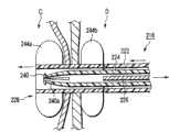
如图34及图35所示,带球囊的导管228具有筒状构件242和1对球囊244a、244b。前端侧的球囊244a及基端侧的球囊244b分别与各自的管路246a、246b相连接,并各自进行膨胀和收缩。在这些管路246a、246b的基端可相对于它们装卸地分别连接有阀248a、248b。注射器250可相对于管路246a、246b的基端装卸。 As shown in FIGS. 34 and 35 , the balloon-attached
接着,对本实施方式的内窥镜系统10的作用进行说明。 Next, the operation of the
如第2实施方式说明的那样,将超声波内窥镜12的插入部22的前端插入至十二指肠D中。然后,通过超声波图像来确认总胆管C的位置。 The distal end of the
使球囊留置器具216的针构件操作部236相对于内套操作部234向基端侧移动,以减小针构件226的前端从内套224的前端突出的量。 The needle
使球囊留置器具216通过钳子通道38而从内窥镜12的插入部22的前端突出。然后,使针构件操作部236相对于内套操作部234向前方侧移动,以使针构件226从球囊留置器具216的内套224的前端突出。然后,从连接器236a向该针构件226中通入高频电流。于是,在十二指肠D及总胆管C的壁面上形成了穿孔。然后,如图36所示,沿着该穿孔将内套224及带球囊的导管228导入至总胆管C中。如图37所示,此时,特别是在将注射器250 安装在管路246a的基端部之后,打开阀248a而向前端侧的球囊244a中通入气体(空气)或液体(水或生理盐水),使该球囊244a膨胀。然后,关闭阀248a并卸下注射器250。 The balloon
然后,将球囊留置器具216整体向手头侧拉入。因此,总胆管C被拉入至十二指肠D一侧。然后,如图38所示,在将基端侧的球囊244b配设在十二指肠D内部的状态下,使基端侧的球囊244b膨胀。此时,在将注射器250安装在管路246b的基端部之后,打开阀248b,向前端侧的球囊244b中通入气体或液体,使该球囊244b膨胀。然后,关闭阀248b并卸下注射器250。 Then, the entire balloon
因此,总胆管C及十二指肠D的壁部被夹持在各自膨胀了的前端侧的球囊244a与基端侧的球囊244b之间。 Therefore, the walls of the common bile duct C and the duodenum D are sandwiched between the inflated
而且,如图39所示,从内套224中拔出针构件226。于是,爪部240a向径向内方收缩进。因此,从与筒状构件242的前端相面对的位置除去爪部240a。然后,相对于外套222拔出内套224及针构件226。于是,如图40所示,成为这样的状态:带球囊的导管228贯穿十二指肠D的壁面与总胆管C的壁面,且由球囊244a、244b这2个球囊夹持着这些十二指肠D的壁面与总胆管C的壁面。因此,胆汁自总胆管C通过筒状构件242向十二指肠D内排出。 Also, as shown in FIG. 39 , the
将这种状态保持数日,使由球囊244a、244b这2个球囊夹持着的总胆管C及十二指肠D的壁部粘连。在粘连状态稳定而形成了瘘孔的状态下,先使前端侧的球囊244a收缩。此时,在将注射器250安装在管路246a中之后打开阀248a,而将气体或液体从前端侧的球囊244a中放出,使该球囊244a收缩。 This state is maintained for several days, and the walls of the common bile duct C and the duodenum D sandwiched by the two
然后,向十二指肠D一侧拉筒状构件242。于是,如图41所示,从十二指肠D一侧取出筒状构件242,剩下了瘘孔F。而且,使基端侧的球囊244b也与前端侧的球囊244a同样地收缩, 使用内窥镜12回收带球囊的导管228。 Then, the
如以上说明的那样,采用本实施方式可以说能达到以下效果。 As described above, according to this embodiment, it can be said that the following effects can be achieved. the
可以由带球囊的导管228的前端侧的球囊244a和基端侧的球囊244b夹持十二指肠D及总胆管C的壁面。因此,可以由筒状构件242可靠地形成瘘孔。 The wall surfaces of the duodenum D and the common bile duct C can be clamped by the
另外,在本实施方式中,说明了如上述那样地可装卸地设置阀248a、248b的情况,但也适合替代阀248a、248b而采用以下这样的构造。 In addition, in this embodiment, the case where the
如图42A及42B所示,带球囊的导管228的第1管路246a通过筒状构件242的内腔而从基端侧延伸出。如图43所示,在与前端侧及基端侧的球囊244a、244b连通的管路246a、246b的基端部分别配设有止回阀252a、252b。管路246a、246b形成为在十二指肠D与总胆管C之间形成瘘孔时其基端部始终配置在十二指肠D内部这样的长度。 As shown in FIGS. 42A and 42B , the
如图44所示,在通过止回阀252b向球囊244b中注入气体(空气)或液体(生理盐水)等时,将细管254配设在管路246b中进行注入。在球囊244b膨胀之后,可通过止回阀252b防止跑出空气或生理盐水,因此可维持膨胀状态。 As shown in FIG. 44 , when injecting gas (air) or liquid (physiological saline) into the
通过粘连形成了瘘孔之后,在为了保留该瘘孔而使球囊244b收缩的情况下,如图45A所示,在管路246b的比止回阀252b更接近球囊244b的位置开孔(设置切口),或者如图45B所示,切掉包括止回阀252b在内的管路246b。于是,气体或生理盐水从球囊244a、244b中漏出,而使球囊收缩。此时,在比第2管路246b更靠前的第1管路246a中开孔,或者切掉第1管路246a。然后,使前端侧的球囊244a收缩,而将带球囊的导管228从十二指肠D一侧拉出。之后,也相同地使基端侧的球囊244b 收缩,使用内窥镜12回收这些球囊。 After the fistula is formed by adhesion, when the
这样,可在将与具有止回阀252a、252b的管路246a、246b连接的带球囊的导管228的管路246a、246b的端部配设在体内的状态下,使球囊244a、244b膨胀和收缩。 In this way, the
接着,使用图46~图51说明第5实施方式。本实施方式为第4实施方式的变型例,对与第4实施方式中说明的构件相同的构件标注相同的附图标记,省略其详细说明。 Next, a fifth embodiment will be described using FIGS. 46 to 51 . This embodiment is a modified example of the fourth embodiment, and the same members as those described in the fourth embodiment are denoted by the same reference numerals, and detailed description thereof will be omitted. the
如图46所示,与第4实施方式相同,球囊留置器具216具有外套222、内套224、针构件226、带球囊的导管228和操作部230。内套224的前端部形成为:前端侧壁厚较薄,而其基端侧通过台阶而壁厚较厚。带球囊的导管228可装卸地配设在内套224的前端侧的壁厚较薄的部分的外周面,且配设在外套222的前端侧的位置。 As shown in FIG. 46 , a balloon
如图47A及47B所示,带球囊的导管228具有第1筒状构件262a、第2筒状构件262b、和第1及第2球囊244a、244b。在第1筒状构件262a的前端部的外周面配设有第1球囊244a。在第1筒状构件262a的基端部的外周面形成有第1齿部264a。 As shown in FIGS. 47A and 47B , the
在第2筒状构件262b的前端部的外周面配设有第2球囊244b。在第2筒状构件262b的前端部的内周面形成有可与第1齿部264a卡合的第2齿部264b。外套222配设在该第2筒状构件262b的基端侧。该外套222可相对于内套224进行相对移动。因此,可朝前端侧按压第2筒状构件262b的基端。因此,通过使外套222相对于内套224移动,可使第1球囊244a与第2球囊244b之间的距离伸缩。而且,由于第1齿部264a与第2齿部264b以齿卡合,因此可将两者固定在轴向的任意位置。 The
接着,对本实施方式的内窥镜系统10的作用进行说明。 Next, the operation of the
将超声波内窥镜12的插入部22的前端插入至十二指肠D 中。而且,通过超声波图像确认总胆管C的位置。 Insert the front end of the
使球囊留置器具216的针构件操作部236相对于内套操作部234向基端侧移动,以减小针构件226的前端从内套224的前端突出的量。 The needle
使球囊留置器具216通过钳子通道38而从内窥镜12的插入部22的前端突出。然后,使针构件226从球囊留置器具216的前端突出,并向该针构件226中通入高频电流。于是,在十二指肠D及总胆管C的壁面上形成了穿孔。而且,如图48所示,沿着该穿孔将内套224及带球囊的导管228导入至总胆管C中。如图49所示,此时,特别是向管路246a中通入气体或液体,使前端侧的球囊244a膨胀。 The balloon
然后,将球囊留置器具216整体拉向手头侧。因此,总胆管C被拉向十二指肠D一侧。而且,如图50所示,在将基端侧的球囊244b配设在十二指肠D内部的状态下,使基端侧的球囊244b膨胀。因此,总胆管C及十二指肠D的壁部配设在前端侧的第1球囊244a与基端侧的第2球囊244b之间。 Then, the entire balloon
然后,使外套222相对于内套224向前方移动。于是,一边以齿卡合,一边使第2筒状构件262b的第2球囊244b逐渐靠近第1筒状构件262a的第1球囊244a。因此,如图51所示,通过使膨胀的第1及第2球囊244a、244b相互靠近,夹持前端侧的第1球囊244a与基端侧的第2球囊244b之间的总胆管C及十二指肠D的壁部。 Then, the
之后,从内套224中拔出针构件226。于是,爪部240a向径向内方收缩。因此,从与第1筒状构件262a的前端相面对的位置a除去爪部240。然后,相对于外套222拔出内套224。于是,形成这样的状态:带球囊的导管228贯穿十二指肠D的壁面与总胆管C的壁面,且由球囊244a、244b这2个球囊夹持着这些十 二指肠D的壁面与总胆管C的壁面。因此,胆汁自总胆管C通过第1筒状构件262a向十二指肠D内排出。 Thereafter, the
将这种状态保持数日,使由球囊244a、244b这2个球囊夹持着的总胆管C及十二指肠D的壁部粘连。在粘连状态稳定而形成了瘘孔的状态下,先使前端侧的球囊244a收缩。然后,向十二指肠D一侧拉第1及第2筒状构件262a、262b。于是,从十二指肠D一侧取出第1及第2筒状构件262a、262b,剩下瘘孔。然后,也使基端侧的球囊244b收缩,使用内窥镜12回收带球囊的导管228。 This state is maintained for several days, and the walls of the common bile duct C and the duodenum D sandwiched by the two
之后的作用与第4实施方式说明的作用相同。因此,省略对作用的说明。 Subsequent operations are the same as those described in the fourth embodiment. Therefore, the description of the action is omitted. the
如以上说明的那样,采用本实施方式可以说能达到以下效果。 As described above, according to this embodiment, it can be said that the following effects can be achieved. the
可以增大前端侧的球囊244a与基端侧的球囊244b之间的距离。即,可以容易地获得将十二指肠D及总胆管的壁面配置在各自膨胀的前端侧的球囊244a与基端侧的球囊244b之间的状态。之后,通过使基端侧的球囊244b靠近前端侧的球囊244a,可以可靠地夹持十二指肠D及总胆管的壁面。因此,可以使十二指肠D与总胆管C之间可靠地紧贴,而更可靠地形成瘘孔。 The distance between the
接着,使用图52及图53说明第6实施方式。本实施方式为第4实施方式的变型例,对与第4实施方式中说明的构件相同的构件标注相同的附图标记,省略其详细说明。 Next, a sixth embodiment will be described using FIGS. 52 and 53 . This embodiment is a modified example of the fourth embodiment, and the same members as those described in the fourth embodiment are denoted by the same reference numerals, and detailed description thereof will be omitted. the
如图52所示,在前端侧的第1球囊244a与基端侧的第2球囊244b之间配设有第3球囊244c。如图53所示,该第3球囊244c的最大外径小于第1及第2球囊244a、244b的最大外径。 As shown in FIG. 52 , the
在此,如上述那样,第1及第2球囊244a、244b被用于夹持总胆管C的壁面与十二指肠D的壁面。因此,第1及第2球囊 244a、244b之间的第3球囊244c被用于扩大瘘孔。于是,通过使第3球囊244c膨胀,可以增大瘘孔的孔径。 Here, the first and
接着,使用图54A~图59说明第7实施方式。本实施方式为第2实施方式的变型例,对与第2实施方式中说明的构件相同的构件标注相同的附图标记,省略其详细说明。 Next, a seventh embodiment will be described using FIGS. 54A to 59 . This embodiment is a modified example of the second embodiment, and the same members as those described in the second embodiment are denoted by the same reference numerals, and detailed description thereof will be omitted. the
内窥镜系统10具有电子凸起型超声波内窥镜12和超声波观察用穿刺针116(参照图22)。如图54A及图55所示,在该穿刺针116的针管146中,沿其长度方向轴线方向形成有侧孔312。如图54A及图54B所示,在针管146中从该侧孔312可装卸地配设有附带线状构件324的磁体(第1磁体)322。该磁体322在前端部的外周面形成有支点部326。该支点部326与侧孔312的前端抵接,能以该侧孔312的前端为支点转动。另一方面,在磁体322的基端部、即与侧孔312的基端相面对的一侧形成有斜面部328。通过使可插拔的管心针148的前端与该斜面部328相抵接,可一边容易地使磁体322以支点部326为支点转动、一边向外方排出磁体322。即,斜面部328为在要使磁体322以支点部326为支点从侧孔312脱落时施力的部分。 The
另外,由内窥镜12运送到体腔内的后述第2磁体330形成为具有可覆盖第1磁体322的多个面中最大的面的面积。 In addition, the
接着,对本实施方式的内窥镜系统10的作用进行说明。 Next, the operation of the
将超声波内窥镜12的插入部22的前端插入至十二指肠D中。然后,通过超声波图像确认总胆管C的位置。 The distal end of the
用拔出了管心针148状态下的超声波观察用穿刺针116的针管146贯穿十二指肠D及总胆管C。然后,将管心针148插入针管146中,用管心针148的前端按压磁体322的斜面部328。于是,如图56所示,借助磁体322的支点部326使磁体322转动,将其排出到针管146的外部。此时,与磁体322连结的线状构件 324维持着贯穿十二指肠D及总胆管C的状态,同时线状构件324的基端被留在十二指肠D一侧。而且,从十二指肠D及总胆管C中拔出针管146,并从内窥镜12的钳子通道38中拔出超声波观察用穿刺针116。 The
然后,如图57所示,重新从钳子通道38中向十二指肠D的内部导入在前端把持着第2磁体330的处理器具(把持钳子)332。然后,通过由内窥镜12进行的光学观察,识别出与第1磁体322连结的线状构件324的存在。 Then, as shown in FIG. 57 , the treatment instrument (holding forceps) 332 holding the
将第2磁体330配置在十二指肠D内,从而凭借由磁体产生的吸引力使第1磁体322与第2磁体330互相吸引。因此,如图58所示,通过第1及第2磁体322、330的作用,使总胆管C与十二指肠D的外壁相互紧贴。此时,通过操作与第1磁体322连结的线状构件324,可以调整磁体322、330的位置。而且,通过磁体322、330相互的吸引力压迫被第1磁体322和第2磁体330夹持着的部分,从而使该部分缺血。使这种缺血持续较长的时间,从而使该部分的组织坏死。此时,第2磁体330的面积大于第1磁体322的面积而仅压迫第1磁体322与总胆管C的内壁紧贴着的部分,因此,该部分的组织坏死。 The
而且,在该已坏死的部分形成瘘孔F。此时,由于第2磁体330的面积大于第1磁体322的面积,因此第1磁体322可通过瘘孔F,而第2磁体330不能通过瘘孔F。因此,如图59所示,第1及第2磁体322、330在受到了磁体相互吸引力的状态(紧贴状态)下脱落至十二指肠D一侧。然后,总胆管C与十二指肠D粘连而维持瘘孔F。 Furthermore, a fistula F is formed in this necrotic portion. At this time, since the area of the
另外,由于线状构件324连结在第1磁体322上,因此,脱落了的第1及第2磁体322、330处于在十二指肠D的内部被牵拉的状态。因此,向十二指肠D一侧拉贯穿于内窥镜12的钳子通 道38的线状构件324,而从总胆管C与十二指肠D的壁面拔出线状构件324。然后,在该状态下用内窥镜12回收磁体322、330,或使磁体322、330落至十二指肠D内而将其排出。 In addition, since the
如以上说明的那样,采用本实施方式可以说能达到以下效果。 As described above, according to this embodiment, it can be said that the following effects can be achieved. the
由于第1磁体322小于第2磁体330,因此可以将因缺血而坏死的部分限制在第1磁体322与总胆管C紧贴着的区域。因此,可以防止第2磁体330脱落至总胆管C一侧。 Since the
接着,用图60~图76说明第8实施方式。本实施方式为第7实施方式的变型例,对与第7实施方式中说明的构件相同的构件标注相同的附图标记,省略其详细说明。 Next, an eighth embodiment will be described with reference to FIGS. 60 to 76 . This embodiment is a modified example of the seventh embodiment, and the same members as those described in the seventh embodiment are denoted by the same reference numerals, and detailed description thereof will be omitted. the
如图60所示,内窥镜系统10具有电子凸起型超声波内窥镜12和磁体组件留置器具416。 As shown in FIG. 60 , the
如图61所示,磁体组件留置器具416具有外套422、推动器(内套)424、操作部426和前端具有钩428a的线428。外套422、推动器424和线428具有在穿过内窥镜12的钳子通道38时随着内窥镜12的插入部22的弯曲状况而弯曲的挠性。推动器424由例如金属材料制的线圈等形成。 As shown in FIG. 61 , the magnet assembly
操作部426具有操作部主体432、和可相对于该操作部主体432滑动的滑动件(钩操作部)434。管状的推动器424固定在操作部主体432的前端。外套422配设在推动器424的外周。线428贯穿于推动器424的内部,线428的基端固定在滑动件434上。 The operation part 426 has an operation part main body 432 and a slider (hook operation part) 434 slidable with respect to the operation part main body 432 . The
在线428前端的钩428a上配设有图62A及图62B所示的磁体组件440。如图62A及图62B所示,磁体组件440具有环状的线状构件442、借助该线状构件442并列设置的多个磁体444、和防止磁体444从线状构件442中脱出的止挡件446。如图62B 所示,相邻的磁体444相互沿着线状构件442移动并磁力吸引到一起,从而使磁体组件440成为大致圆环状。 The
止挡件446沿线状构件442移动,而使线状构件442的环状部分的大小变化。该止挡件446借助摩擦力与线状构件442卡合。另外,止挡件446由例如硅胶材料等形成。 The
如图63A及图63B所示,磁体444可使用圆盘状或矩形盘状等各种形状。另外,在图63B所示的磁体444的中央形成有四方空间(除了圆形之外的空间),该四方空间供线状构件442贯穿。另一方面,与图63B所示的磁体444组装在一起的线状构件442的横截面形成为例如矩形(形成为除了圆形之外的形状)。因此,可防止各磁体444绕线状构件442的轴线旋转。另外,如图64A所示,通过使各磁体444的前端面侧及基端面侧带有鼓出,可以如图64B所示那样地在维持着磁体444相互连结的状态下使磁体444相互向适当的方向弯曲。 As shown in FIG. 63A and FIG. 63B , various shapes such as a disk shape or a rectangular disk shape can be used for the
另外,如图65所示,各磁体444适合形成为内周侧弦或圆弧(圆周)短于外周侧弦或圆弧(圆周),使得在互相相邻的多个磁体444相互磁力吸引时到一起成为圆环状。在这种情况下,当使止挡件446向线状构件442的前端侧移动而使磁体444相互沿线状构件442磁力吸引到一起时,逐渐成为圆环状。因此,磁体组件440聚拢成大致圆环状。而且,通过适当设定内周侧弦与外周侧弦之比,可以规定成为圆环状的磁体群的直径。 In addition, as shown in FIG. 65 , each
接着,对本实施方式的磁体组件留置器具416的作用进行说明。在此,对采用图62A及图62B所示的磁体组件440的情况进行说明。 Next, the action of the magnet assembly indwelling
首先,如图66A所示,预先以从磁体组件留置器具416的外套422的前端拉入的状态配设磁体组件440。此时,多个磁体444借助线状构件442被并列设置成直线状。First, as shown in FIG. 66A , the
如图66B所示,在这种状态下,在相对于推动器424拉入磁体组件留置器具416的外套422时,使得磁体组件440的线状构件442的前端及止挡件446推出到外部。在该状态下,相对于图61所示的操作体主体432操作滑动件434,而将线428拉向手头侧。于是,由钩428a向手头侧拉入线状构件442。因此,如图66C所示,止挡件446向前方进行相对移动,使线状构件442前端侧的环收缩。在该状态下,操作图61所示的滑动件434,而使线428向前端侧移动。于是,钩428a从推动器424的前端突出。因此,如图66D所示,钩428a与线状构件442的卡合脱开,磁体组件440离开磁体组件留置器具416。 As shown in FIG. 66B , in this state, when the
接着,对本实施方式的内窥镜系统10的作用进行说明。 Next, the operation of the
将超声波内窥镜12的插入部22的前端插入至十二指肠D中。然后,通过超声波图像确认总胆管C的位置。 The distal end of the
在内窥镜12的钳子通道38中使用上述第2实施方式中说明的穿刺针116(参照图22),自十二指肠D向总胆管C开设孔H1、H2。 Holes H 1 , H2 are opened from the duodenum D to the common bile duct C in the
如图67所示,使磁体组件留置器具416的外套422的前端通过用穿刺针(未图示)开设的孔H1、H2而将该前端导入总胆管C的内部。然后,如上述那样,使磁体组件440离开磁体组件留置器具416。即,如图68所示,磁体组件440放出至总胆管C内。然后,从钳子通道38中拔出磁体组件留置器具416。 As shown in FIG. 67 , the front end of the
之后,使第2磁体通过钳子通道38导入到十二指肠D的内部(参照图57),该第2磁体的外径大于由磁体组件440的圆环状磁体群形成的外径。于是,如图69所示,磁体组件440隔着总胆管C的壁面及十二指肠D的壁面与第2磁体330紧贴。因此,十二指肠D与总胆管C紧贴。 Afterwards, the second magnet is introduced into the duodenum D through the forceps channel 38 (see FIG. 57 ), and the outer diameter of the second magnet is larger than that formed by the ring-shaped magnet group of the
如以上说明的那样,采用本实施方式可以说能达到以下效 果。 As described above, the present embodiment can be said to achieve the following effects: fruit. the
组装磁体组件440的多个磁体444而做成环状等,从而可以增大缺血的面积。而且,即使未通过磁体444的作用压迫环状部分的内侧,但由于可抑制血液的流动,因此环状部分的内侧也可以产生缺血。因此,可以使坏死的部分为环状,从而形成更大的孔。 By assembling the plurality of
另外,如图70所示,将使磁体444为圆环状的磁体组件440用作第1磁体,并使用圆环状的第2磁体330。而且,暂时用穿孔针116(参照图22)对圆环状的第2磁体330与磁体组件(第1磁体)440的成为圆环状的磁体444这两者内侧进行穿孔等。于是,形成了瘘孔,从而不必等到因组织坏死而成为打通,就可以立即排出胆汁。 Moreover, as shown in FIG. 70, the
在本实施方式中,对使用环状的线状构件442的情况进行了说明,但如图71所示,也适合使用直线状的线状构件452而将磁体444并列设置成直线状。在该情况下,在线状构件452的基端形成有用于勾挂于钩428a上的环452a。另外,在线状构件452的前端配设有防止磁体444从线状构件452的前端脱落的、例如球状等的前端止挡件452b。并且,在前端止挡件452b与环452a之间配设有基端止挡件452c,该基端止挡件452c用于防止磁体444从基端侧脱落、并且与前端止挡件452b协作规定磁体444的可动范围。另外,基端止挡件452c也适合使用可沿线状构件452移动的构件(参照图72A)。 In this embodiment, the case of using the ring-shaped
另外,图72A及图72B所示的磁体组件440所使用的磁体444的构造与图65所示的构造相同。因此,当使止挡件446自图72A所示的状态向线状构件452的前端侧移动时,如图72B所示,相邻的磁体444磁力吸引而成为圆环状。 In addition, the structure of the
并且,如图72C所示,最靠近止挡件446的磁体444的穿过 线状构件452的孔部分弯曲。因此,可防止止挡件446进入到(参照图72B)磁体444之间。即,使穿过最靠近止挡件446一侧的磁体444的线状构件452从磁体444的外周侧面伸出,从而防止了止挡件446被配设在磁体444之间。于是,在多个磁体444互相磁力吸引时,成为更加接近圆环状的形状。 And, as shown in FIG. 72C, the passage of the
另外,当如图73C所示那样并列设置图73A所示的磁体456及图73B所示的非磁性体(隔离件)458时,如图73D所示,可以获得相当于较大的C字状磁体的磁力。即,可以汇集较小的磁体456而产生较大的磁力。与图66A~图66D所示的情况相同地使用该磁体组件440。因此,即使各磁体456磁力和尺寸较小,也可以获得可适当设定尺寸的、也可设定磁力大小的磁体组件440。 In addition, when the
如图74B所示那样在使图74A所示的棒状磁体462磁力吸附时,图74B所示的磁体462与具有2块图74A所示的磁体462量的磁力的1块磁体大致相当。因此,在将小型的磁体462维持在规定的朝向和位置关系而使它们相互连结时,可以得到与可借助细小管腔或狭窄部来留置大型磁体的效果相同的效果。 As shown in FIG. 74B , when the
另外,在本实施方式中,对自一方管腔(第1管腔)向另一方管腔(第2管腔)各自的壁面进行穿孔而将磁体组件440放出到总胆管C的内部的情况进行了说明,但对此还有几种其它的方法。 In addition, in this embodiment, the case where the
如图75所示,例如,操作内窥镜12,将磁体组件留置器具416的前端自十二指肠D的乳头状突起P导入至总胆管C的内部。然后,操作磁体组件留置器具416而将磁体组件440排出到总胆管C的内部。之后,同样地将第2磁体330导入到十二指肠D内。因此,磁体组件440的磁体444与十二指肠D内的第2磁体330磁力吸引。As shown in FIG. 75 , for example, the
对于将磁体组件440放出到总胆管C的内部的操作还有其它的做法。 There are other approaches to deploying the
在图76中示出了经皮经肝胆管导液装置(PCTD)。这是一种自体外通过腹部的体壁W而从配设在总胆管C中的管466排出胆汁的方法。 A percutaneous transhepatic biliary catheter device (PCTD) is shown in FIG. 76 . This is a method of expelling bile from the tube 466 arranged in the common bile duct C through the body wall W of the abdomen from outside the body. the
向该管466中插入磁体组件留置器具416,并向胆管C内放出磁体组件440。然后,经过口腔将内窥镜12的插入部22导入至十二指肠D,而使第2磁体330与磁体组件440的磁体444磁力吸引。 The magnet assembly indwelling
接着,使用图77A~图83G说明第9实施方式。本实施方式为第8实施方式的变型例,对与第8实施方式中说明的构件相同的构件标注相同的附图标记,省略其详细说明。 Next, a ninth embodiment will be described using FIGS. 77A to 83G . This embodiment is a modified example of the eighth embodiment, and the same members as those described in the eighth embodiment are denoted by the same reference numerals, and detailed description thereof will be omitted. the
如图77A所示,磁体组件留置器具416具有壳472、推动器474和操作部476。操作部476具有操作部主体482和可沿操作部主体482滑动的滑动件484。 As shown in FIG. 77A , the magnet assembly
如图77A及图77B所示,壳472具有2个内径不同的腔管(双腔管)486a、486b。在内径较大的第1腔管486a中,以使推动器474与操作部476的滑动件484连结的状态配设有该推动器474。在内径小于第1腔管486a内径的第2腔管486b中贯穿有线状构件452。而且,在第2腔管486b的基端部形成有用于使线状构件452的基端部侧向磁体组件留置器具416的外侧延伸出的侧孔488。 As shown in FIGS. 77A and 77B , the
如图78所示,在磁体组件留置器具416中配设有磁体组件440。在磁体组件留置器具416的第1腔管486a中,以贯穿于线状构件452的状态配设有磁体492、前端止挡件494、后端止挡件496及隔离件498。并且,推动器474的前端抵接于后端止挡件496。另外,线状构件452穿过壳472的前端将第1腔管486a 与第2腔管486b连接起来。前端止挡件494以被向比壳472前端更靠近基端一侧的位置拉入的状态临时固定在壳472(第1腔管486a)中。因此,如后述那样,可简单地解除前端止挡件494相对于壳472的临时固定。 As shown in FIG. 78 , a
如图79所示,在磁体492中形成有通孔492a、该通孔492a供线状构件452沿将S极和N极相连接的方向贯穿。而且,磁体492的通孔492a的一端(图79中的左端部)的缘部形成为锥状。即,各磁体492的通孔492a的一端形成为沉孔状。 As shown in FIG. 79 , a through
如图80A所示,在配设于多个磁体492前端侧的前端止挡件494中形成有可供线状构件452贯穿的通孔494a。在该通孔494a的一端(图81A中的左端部)配设有图80B所示的楔状构件494b,该楔状构件494b若被施加较大的力就会嵌入该通孔494a的一端。为此,前端止挡件494及楔状构件494b由可使楔状构件494b嵌入前端止挡件494中的材料形成。另外,为了防止前端止挡件494从壳472前端侧进入到第2腔管486b的内部,前端止挡件494形成为可通过第1腔管486a、而不能通过第2腔管486b的尺寸。 As shown in FIG. 80A , a through-
如图81A所示,在配设在多个磁体492基端侧的基端止挡件496中形成有可供线状构件452贯穿的通孔496a。在该通孔496a的一端(图80A中的右端部)配设有图81B所示的楔状构件496b,该楔状构件496b若被施加较大的力就会嵌入该通孔496a的一端。为此,基端止挡件496及楔状构件496b由可使楔状构件496b嵌入到基端止挡件496中的材料形成。另外,基端止挡件496固定着已贯穿于通孔496a中的线状构件452。 As shown in FIG. 81A , a through
如图78所示,图82所示的隔离件498配设在相邻的磁体492之间。在该隔离件498中形成有可供线状构件452贯穿的通孔498a。隔离件498由柔软的硅树脂材料形成。各隔离件498在被 强力挤入磁体492之间时进入到图79所示的磁体492的锥状(沉孔状)的缘部中。 As shown in FIG. 78 ,
接着,对本实施方式的内窥镜系统10的作用进行说明。 Next, the operation of the
如图83A所示,将磁体组件留置器具416的壳472的前端配设在总胆管C的内部。然后,向壳472的前端侧推入推动器474。于是,解除前端止挡件494与壳472之间的临时固定,使前端止挡件494从壳472的前端突出。 As shown in FIG. 83A , the front end of the
如图83B所示,向手头侧以较强力拉第2腔管486b一侧的线状构件452。于是,前端止挡件494成为不能从壳472的前端侧进入第2腔管486b中而临时固定在壳472前端的状态。因此,如图83C所示,基端止挡件496与前端止挡件494之间的距离被缩短。即,隔离件498进入到磁体492的通孔492a的锥状的缘部中,并且如图83D所示那样,相邻的磁体492相互磁力吸附。此时,如上述那样,相当于具有S极及N极的较大的磁体(参照图83E)。并且,当拉线状构件452而施加压力时,前端止挡件494及后端止挡件496的楔状构件494b、496b分别嵌入到前端止挡件494及后端止挡件496中。因此,前端止挡件494与后端止挡件496之间的线状构件452的距离被固定。 As shown in FIG. 83B, the
如图83F所示,向壳472的前端侧推入推动器474,使一体化了的磁体492自壳472的前端向外侧伸出。 As shown in FIG. 83F , the
如图83G所示,向手头侧拔出推动器474和壳472。因此,固定在线状构件452上的磁体被留置在总胆管C的内部。另外,在线状构件452的长度过长时,可通过切断该线状构件452等来调整其长度。 As shown in FIG. 83G, the
在该状态下,与第7实施方式相同,使生物体组织坏死,而在总胆管C与十二指肠D之间形成瘘孔。而且,在形成瘘孔之后,磁体492与线状构件452一同落到十二指肠D内。In this state, as in the seventh embodiment, the living tissue is necrotic, and a fistula is formed between the common bile duct C and the duodenum D. FIG. Also, the
如以上说明的那样,采用本实施方式可以说能达到以下效果。 As described above, according to this embodiment, it can be said that the following effects can be achieved. the
在使磁体组件留置器具416贯穿于内窥镜12的钳子通道38时,可借助隔离件498防止磁体492相互的磁力吸附,因此可以容易地沿着体腔的形状贯穿其间。 When the magnet assembly indwelling
另外,通过将磁力较小的磁体492相互连结在一起,可以将其作为面积较大、且磁力较大的磁体来使用。 In addition, by connecting the
因此,在将各磁体492插入内窥镜12的钳子通道38中时,各磁体492隔着隔离件498相分离,因此易于插入,在排出到总胆管C的内部的时刻,可以作为磁力及尺寸较大的磁体排出。 Therefore, when each
接着,用图84~图85E说明第10实施方式。本实施方式为第9实施方式的变型例,对与第9实施方式中说明的构件相同的构件标注相同的附图标记,省略其详细说明。 Next, a tenth embodiment will be described with reference to FIGS. 84 to 85E. This embodiment is a modified example of the ninth embodiment, and the same members as those described in the ninth embodiment are denoted by the same reference numerals, and detailed description thereof will be omitted. the
与第9实施方式说明的壳472不同,图84所示的磁体组件留置器具416由1个腔管(单腔管)形成。 Unlike the
如图85A及图85C所示,磁体组件440在磁体492之间配设有易于自线状构件452脱落的、由生物适合性材料形成的隔离件500。因此,随着磁体492从壳472的前端突出,隔离件500脱落,相邻的磁体492相互磁力吸附。 As shown in FIGS. 85A and 85C , the
另外,在本实施方式中,与第9实施方式不同,前端止挡件494与线状构件452互相相对固定,但基端止挡件496可相对于线状构件452移动。 In addition, in this embodiment, unlike the ninth embodiment, the
接着,对本实施方式的内窥镜系统10的作用进行说明。 Next, the operation of the
如图85A所示,将磁体组件留置器具416的壳472的前端穿过十二指肠D而配设在总胆管C中。 As shown in FIG. 85A , the front end of the
如图85B所示,使推动器474向壳472的前端侧移动。前端止挡件494及磁体492从壳472的前端突出。于是,隔离件500 从磁体492之间脱落。因此,如图85C所示,相邻的磁体492相互磁力吸附。 As shown in FIG. 85B , the
而且,在隔离件500脱落的同时,相邻的磁体492相互依次磁力吸附。然后,使推动器474向前移动,而将基端止挡件496的楔状构件与线状构件452相卡合、固定。因此,如图85D所示,多个磁体492被磁力吸附而相当于1个磁力较大的磁体。 Moreover, when the
而且,如图85E所示,在将磁体492配置在总胆管C内的状态下,拔出壳472及推动器474。脱落下来的隔离件500由生物体吸收性材料形成,由于其不久就会被体内吸收,因此不会残留在胆管C内。 Then, as shown in FIG. 85E , with the
如以上说明的那样,采用本实施方式可以说能达到以下效果。 As described above, according to this embodiment, it can be said that the following effects can be achieved. the
由于磁体组件留置器具416使用了单腔管的壳472,因此与双腔管的情况相比,可以使磁体组件留置器具416的壳472的直径变得更细。 Since the magnet assembly
另外,在本实施方式中,对使十二指肠D与总胆管C相吻合的情况进行了说明,但也可以使胃S与空肠J相吻合。在这种情况下,由于可以直接将隔离件500排出到空肠J中,因此隔离件500不需要由生物体吸收性材料形成。 In addition, in this embodiment, the case where the duodenum D and the common bile duct C are anastomosed has been described, but the stomach S and the jejunum J may be anastomosed. In this case, since the
接着,用图86~图87B说明第11实施方式。本实施方式为第10实施方式的变型例,对与第10实施方式中说明的构件相同的构件标注相同的附图标记,省略其详细说明。 Next, an eleventh embodiment will be described with reference to FIGS. 86 to 87B. This embodiment is a modified example of the tenth embodiment, and the same members as those described in the tenth embodiment are denoted by the same reference numerals, and detailed description thereof will be omitted. the
如图86所示,在磁体组件留置器具416的壳472中配设有第1及第2线状构件454a、454b。 As shown in FIG. 86 , first and second
如图87A及图87B所示,在磁体492、前端止挡件494、后端止挡件496和推动器474中贯穿有第1线状构件454a。在第2线状构件454b的前端部每隔规定间隔就固定有多个隔离件 500。因此,可以在手头侧把持第2线状构件454b的基端,而可容易地回收脱落了的隔离件500。 As shown in FIGS. 87A and 87B , the first
根据以上说明,可获得以下的技术方案。 According to the above description, the following technical solutions can be obtained. the
1.一种瘘孔形成方法,该瘘孔形成方法用于在第1管腔和第2管腔之间形成瘘孔,其包括以下步骤: 1. A method for forming a fistula, which is used to form a fistula between the first lumen and the second lumen, comprising the following steps:
用穿刺针自上述第1管腔内通过上述第1管腔的壁面、上述第2管腔的壁面穿刺至上述第2管腔内; Use a puncture needle to puncture from the first lumen through the wall of the first lumen and the wall of the second lumen into the second lumen;
将上述穿刺针配置在中心轴线的位置,用线圈针在上述穿刺针的周围自上述第1管腔向第2管腔进行穿刺,使第1管腔和第2管腔相连接; Arrange the above-mentioned puncture needle at the position of the central axis, and use a coil needle to puncture from the above-mentioned first lumen to the second lumen around the above-mentioned puncture needle, so that the first lumen and the second lumen are connected;
在使上述第1管腔和第2管腔相连通着的状态下维持上述线圈针; Maintain the above-mentioned coil needle in a state where the above-mentioned first lumen and the second lumen are connected;
在上述线圈针的内侧形成瘘孔。 A fistula hole is formed inside the coil needle. the
2.根据技术方案1所述的瘘孔形成方法,该瘘孔形成方法还包括以下步骤: 2. According to the fistula formation method described in technical scheme 1, the fistula formation method also includes the following steps:
在将上述线圈针的基端卡合在套管的前端的状态下,将上述套管配置在内窥镜的插入部的外周,将上述线圈针导入到上述第1管腔内。 With the proximal end of the coil needle engaged with the distal end of the cannula, the cannula is arranged on the outer periphery of the insertion portion of the endoscope, and the coil needle is introduced into the first lumen. the
3.根据技术方案2所述的瘘孔形成方法,该瘘孔形成方法还包括以下步骤: 3. According to the fistula formation method described in technical scheme 2, the fistula formation method also includes the following steps:
在解除上述套管与上述线圈针之间的卡合时,使上述套管绕其轴线旋转。 When the engagement between the sleeve and the coil needle is released, the sleeve is rotated around its axis. the
4.一种超声波内窥镜,该超声波内窥镜包括细长的插入部、和操作部,上述插入部具有前端部和基端部,上述操作部设在上述插入部的基端部; 4. An ultrasonic endoscope comprising an elongated insertion portion and an operation portion, the insertion portion having a front end portion and a base end portion, and the operation portion being located at the base end portion of the insertion portion;
上述插入部在上述前端部的前端面具有前端硬质部,该前端硬质部在一条直线上具有超声波振子、钳子通道开口部和物 镜。 The above-mentioned insertion part has a front-end hard part on the front-end surface of the above-mentioned front-end part, and the front-end hard part has an ultrasonic vibrator, a forceps channel opening and anmirror. the
5.根据技术方案4所述的超声波内窥镜,上述钳子通道开口部配设在上述前端硬质部的中心轴线上,上述超声波振子及上述物镜的中心轴线处于相对于上述前端硬质部的中心轴线大致对称的位置。 5. The ultrasonic endoscope according to
6.一种瘘孔形成方法,该瘘孔形成方法用于在第1管腔和第2管腔之间形成瘘孔,其包括以下步骤: 6. A method for forming a fistula, which is used to form a fistula between the first lumen and the second lumen, comprising the following steps:
用穿刺针自上述第1管腔内穿刺至第1管腔外; Use a puncture needle to puncture from the above-mentioned first lumen to the outside of the first lumen;
将粘接剂自上述穿刺针排出到第1管腔与第2管腔之间; Discharge the adhesive from the above-mentioned puncture needle between the first lumen and the second lumen;
使上述第1管腔和第2管腔相对地向对方一侧接近,并用粘接剂使彼此的外壁面相互粘接; Make the above-mentioned first lumen and second lumen relatively approach each other, and use an adhesive to bond the outer walls of each other to each other;
在使上述外壁面相互粘接起来的部分的缘部的内侧形成瘘孔。 A fistula hole is formed inside the edge of the portion where the outer wall surfaces are bonded to each other. the
7.根据技术方案6所述的瘘孔形成方法,该瘘孔形成方法还包括以下步骤: 7. According to the fistula formation method described in technical solution 6, the fistula formation method also includes the following steps:
在自上述第1管腔内向上述第2管腔排出上述粘接剂之前,使用内窥镜的超声波观察功能识别出上述第2管腔的位置。 Before the adhesive is discharged from the first lumen to the second lumen, the position of the second lumen is recognized using an ultrasonic observation function of an endoscope. the
8.根据技术方案6所述的瘘孔形成方法,该瘘孔形成方法还包括以下步骤: 8. According to the fistula formation method described in technical solution 6, the fistula formation method also includes the following steps:
使用内窥镜将上述穿刺针导入到上述第1管腔内。 The puncture needle is introduced into the first lumen using an endoscope. the
9.根据技术方案8所述的瘘孔形成方法,该瘘孔形成方法还包括以下步骤: 9. According to the fistula formation method described in technical solution 8, the fistula formation method also includes the following steps:
向配设在上述内窥镜的插入部的前端部的球囊中加入液体,而使上述球囊膨胀,使上述第1管腔向上述第2管腔一侧移动,使上述第1管腔与上述第2管腔相粘接。 Adding liquid to a balloon disposed at the distal end of the insertion portion of the endoscope to inflate the balloon, move the first lumen to the second lumen side, and move the first lumen to the side of the second lumen. Adhesive to the above-mentioned second lumen. the
10.根据技术方案8所述的瘘孔形成方法,该瘘孔形成方法还包括以下步骤:10. According to the fistula formation method described in technical solution 8, the fistula formation method also includes the following steps:
产生与上述内窥镜所产生的超声波观察用超声波振动不同的、更强力的超声波振动,通过超声波振动使用上述粘接剂粘接着的部分更强力地相互紧贴。 Different from the ultrasonic vibration for ultrasonic observation generated by the above-mentioned endoscope, stronger ultrasonic vibration is generated, and the parts bonded by the above-mentioned adhesive are more strongly adhered to each other by the ultrasonic vibration. the
11.根据技术方案8所述的瘘孔形成方法,该瘘孔形成方法还包括以下步骤: 11. According to the fistula formation method described in technical solution 8, the fistula formation method also includes the following steps:
使用内窥镜配设能量处理器具,该能量处理器具可产生与上述内窥镜所产生超声波观察用超声波振动不同的、更强力的超声波振动,通过超声波振动使用上述粘接剂粘接着的部分更强力地相互紧贴。 Use an endoscope equipped with an energy processing device that can generate stronger ultrasonic vibrations different from the ultrasonic vibrations for ultrasonic observation generated by the above-mentioned endoscope, and use the above-mentioned adhesive to bond the parts through the ultrasonic vibrations cling to each other more strongly. the
12.一种瘘孔形成方法,该瘘孔形成方法用于在第1管腔和第2管腔之间形成瘘孔,其包括以下步骤: 12. A method for forming a fistula, which is used to form a fistula between the first lumen and the second lumen, comprising the following steps:
用穿刺针自上述第1管腔内穿刺至第2管腔内; Use a puncture needle to puncture from the above-mentioned first lumen to the second lumen;
使设在筒状构件的外周面的前端部上的第1球囊通过用上述穿刺针穿刺了的穿孔部,而配设在第2管腔内; Make the first balloon provided on the front end portion of the outer peripheral surface of the cylindrical member pass through the perforation portion punctured with the above-mentioned puncture needle, and be arranged in the second lumen;
使上述第1球囊膨胀; Inflate the first balloon above;
在使上述第1球囊膨胀的状态下,向上述第1管腔一侧推压上述第2管腔的内壁,使上述第2管腔靠近上述第1管腔一侧,并且将设在上述筒状构件的外周面的上述第1球囊的基端侧的第2球囊配设在上述第1管腔内; In the state where the first balloon is inflated, the inner wall of the second lumen is pushed toward the first lumen side, the second lumen is brought close to the first lumen side, and the The second balloon on the base end side of the first balloon on the outer peripheral surface of the cylindrical member is arranged in the first lumen;
使上述第2球囊膨胀,用上述第1及第2球囊夹持上述第1及第2管腔的壁面; Inflate the above-mentioned second balloon, and use the above-mentioned first and second balloons to clamp the walls of the above-mentioned first and second lumens;
在用上述筒状构件的外周面维持着穿孔部的状态下,用上述第1及第2球囊夹持上述第1及第2管腔的壁面,使上述第1及第2管腔的壁面互相粘连; In the state where the perforation portion is maintained by the outer peripheral surface of the cylindrical member, the wall surfaces of the first and second lumens are sandwiched by the first and second balloons so that the wall surfaces of the first and second lumens stick to each other;
使上述第1及第2球囊收缩,并且从上述穿孔部拔出上述筒状构件,从而形成瘘孔。 The first and second balloons are deflated, and the tubular member is pulled out from the perforated portion to form a fistula. the
13.根据技术方案12所述的瘘孔形成方法,该瘘孔形成方 法还包括以下步骤: 13. According to the fistula formation method described in
使用内窥镜,用内窥镜的钳子通道将上述穿刺针导入到上述第1管腔内。 Using an endoscope, the puncture needle is introduced into the first lumen through the forceps channel of the endoscope. the
14.根据技术方案12所述的瘘孔形成方法,该瘘孔形成方法还包括以下步骤: 14. According to the fistula formation method described in
在用上述穿刺针自上述第1管腔内向上述第2管腔进行穿刺之前,使用内窥镜的超声波观察功能识别出上述第2管腔的位置。 Before puncturing the second lumen from the first lumen with the puncture needle, the position of the second lumen is recognized using an ultrasonic observation function of an endoscope. the
15.根据技术方案12所述的瘘孔形成方法,该瘘孔形成方法还包括以下步骤: 15. According to the fistula formation method described in
在使上述第1及第2球囊膨胀时,利用止回阀防止第1及第2球囊收缩,该止回阀设在可使流体相对于上述第1及第2球囊出入的、与上述第1及第2球囊管路连结的流体流路中的残留在上述第1管腔内的部分。 When the above-mentioned first and second balloons are inflated, the first and second balloons are prevented from contracting by using a check valve. A portion of the fluid flow path connecting the first and second balloon tubes remains in the first lumen. the
16.根据技术方案15所述的瘘孔形成方法,该瘘孔形成方法还包括以下步骤: 16. According to the fistula formation method described in technical solution 15, the fistula formation method also includes the following steps:
在使上述第1及第2球囊收缩时,在上述流体管路的上述止回阀与上述球囊之间的至少一部分设置切口。 When the first and second balloons are deflated, at least a part of the fluid line between the check valve and the balloon is provided with a cutout. the
17.一种带球囊的导管,该带球囊的导管用于配设在瘘孔中,其包括: 17. A catheter with a balloon for deployment in a fistula comprising:
筒状构件,其具有前端部和基端部; a cylindrical member having a front end and a base end;
第1球囊,其配设在上述筒状构件的前端部的外周面; a first balloon arranged on the outer peripheral surface of the front end of the cylindrical member;
第2球囊,其配设在上述筒状构件的外周面的上述第1球囊的基端侧; a second balloon disposed on the base end side of the first balloon on the outer peripheral surface of the cylindrical member;
第1流体管路,其与上述第1球囊相连结、用于相对于上述第1球囊放出、注入流体; The first fluid pipeline, which is connected to the first balloon, is used to discharge and inject fluid relative to the first balloon;
第2流体管路,其与上述第2球囊相连结、用于相对于上述 第2球囊放出、注入流体。 The second fluid line, which is connected to the second balloon, is used for relative to the above-mentionedThe second balloon is deflated and filled with fluid. the
18.根据技术方案17所述的带球囊的导管,其中, 18. The catheter with a balloon according to technical solution 17, wherein,
上述第2球囊可在将上述第1球囊固定在上述筒状构件上的状态下朝上述第1球囊移动。 The second balloon is movable toward the first balloon in a state where the first balloon is fixed to the cylindrical member. the
19.根据技术方案18所述的带球囊的导管,其中, 19. The catheter with a balloon according to technical solution 18, wherein,
上述筒状构件包括:第1筒状构件,其配设有上述第1球囊;第2筒状构件,其设在上述第1筒状构件的外侧、并配设有上述第2球囊; The cylindrical member includes: a first cylindrical member provided with the first balloon; a second cylindrical member provided outside the first cylindrical member and provided with the second balloon;
在上述第1筒状构件的外周面及上述第2筒状构件的内周面设有可互相卡合的卡合部。 Engaging portions capable of engaging with each other are provided on the outer peripheral surface of the first cylindrical member and the inner peripheral surface of the second cylindrical member. the
20.根据技术方案17所述的带球囊的导管,其中, 20. The catheter with a balloon according to technical solution 17, wherein,
在上述第1及第2球囊之间具有第3球囊,该第3球囊向上述筒状构件径向外方的膨胀量小于上述第1及第2球囊向上述筒状构件径向外方的膨胀量。 A third balloon is provided between the first and second balloons, and the expansion amount of the third balloon radially outward of the cylindrical member is smaller than that of the first and second balloons in the radial direction of the cylindrical member. The amount of expansion on the outside. the
21.根据技术方案17所述的带球囊的导管,其中, 21. The catheter with a balloon according to technical solution 17, wherein,
上述第1及第2流体管路在各自靠近上述第1及第2球囊的一侧配设有容许上述第1及第2球囊膨胀、防止第1及第2球囊收缩的止回阀。 The first and second fluid pipelines are respectively equipped with check valves on the sides close to the first and second balloons to allow the expansion of the first and second balloons and prevent the first and second balloons from contracting. . the
22.一种瘘孔形成方法,该瘘孔形成方法用于在第1管腔和第2管腔之间形成瘘孔,其包括以下步骤: 22. A method for forming a fistula, which is used to form a fistula between the first lumen and the second lumen, comprising the following steps:
将第1磁体自第1管腔配置在第2管腔内; disposing the first magnet in the second lumen from the first lumen;
将大于上述第1磁体的第2磁体配置在上述第1管腔内,使上述第1及第2磁体夹持上述第1及第2管腔的壁面并相互作用引力; disposing a second magnet larger than the first magnet in the first lumen, so that the first and second magnets clamp the walls of the first and second lumens and interact with each other;
利用第1及第2磁体的引力夹持上述第1及第2管腔,从而使其坏死而形成瘘孔; Utilize the first and second magnets to clamp the above-mentioned first and second lumens, so as to make them necrotic and form fistula holes;
使上述第1磁体通过上述瘘孔而排出到第1管腔内,使第1 及第2磁体脱落在第1管腔内。 The above-mentioned first magnet is discharged into the first lumen through the above-mentioned fistula hole, so that the firstAnd the second magnet falls off in the first lumen. the
23.根据技术方案22所述的瘘孔形成方法,该瘘孔形成方法还包括以下步骤: 23. According to the fistula formation method described in
使用内窥镜将上述第1磁体自上述第1管腔配设在第2管腔内。 The first magnet is placed in the second lumen from the first lumen using an endoscope. the
24.根据技术方案22所述的瘘孔形成方法,该瘘孔形成方法还包括以下步骤: 24. According to the fistula formation method described in
在自上述第1管腔内向上述第2管腔配设上述第1磁体之前,利用内窥镜的超声波观察功能识别出上述第2管腔的位置。 Before disposing the first magnet from the first lumen to the second lumen, the position of the second lumen is recognized using an ultrasonic observation function of the endoscope. the
25.根据技术方案22所述的瘘孔形成方法,该瘘孔形成方法还包括以下步骤: 25. According to the fistula formation method described in
利用内窥镜将上述第1磁体自上述第1管腔导入到第2管腔内。 The first magnet is introduced from the first lumen into the second lumen by using an endoscope. the
26.根据技术方案22所述的瘘孔形成方法,该瘘孔形成方法还包括以下步骤: 26. According to the fistula formation method described in
在自第1管腔向第2管腔内配设第1磁体时,使用带有线状构件的第1磁体,用穿刺针自上述第1管腔内向第2管腔内进行穿刺,而将上述第1磁体配设在上述第2管腔内。 When arranging the first magnet from the first lumen to the second lumen, use the first magnet with a linear member to puncture from the first lumen to the second lumen with a puncture needle, and place the above-mentioned The first magnet is disposed in the second lumen. the
27.根据技术方案26所述的瘘孔形成方法,该瘘孔形成方法还包括以下步骤: 27. According to the fistula formation method described in
在使上述第2管腔向上述第1管腔侧移动时,拉拽与上述第1磁体连结着的线状构件。 When moving the second lumen toward the first lumen, the linear member connected to the first magnet is pulled. the
28.一种磁体留置器具,该磁体留置器具用于留置隔着生物体组织的壁面与其它磁体磁力吸引的磁体,其包括: 28. A magnet indwelling device, the magnet indwelling device is used to indwell a magnet that is magnetically attracted to other magnets across the wall of biological tissue, comprising:
穿刺针,其在前端部具有针管; A puncture needle, which has a needle tube at the front end;
侧孔,其设在上述针管上; side hole, which is located on the above-mentioned needle tube;
磁体,其可相对于上述侧孔出入;a magnet that is accessible relative to the side hole;
管心针,其可相对于上述针管的基端部装卸、并通过其向针管中的插入而从上述侧孔中排出上述磁体。 and a stylet detachable from the base end of the needle tube, and the magnet is ejected from the side hole by being inserted into the needle tube. the
29.根据技术方案28所述的磁体留置器具,其中, 29. The magnet indwelling device according to technical solution 28, wherein,
在上述磁体上固定有线状构件。 A linear member is fixed to the magnet. the
30.一种磁体组件,该磁体组件用于隔着生物体组织的壁面与其它磁体磁力吸引,其包括: 30. A magnet assembly, which is used for magnetic attraction with other magnets across the wall of biological tissue, comprising:
直线状的线状构件; linear linear components;
多个磁体,它们可供上述线状构件贯穿地并列设置; A plurality of magnets, which can be arranged side by side in such a way that the above-mentioned linear member can penetrate;
止挡件,其设在上述线状构件上、并可防止上述磁体自上述线状构件脱落。 The stopper is provided on the above-mentioned linear member, and can prevent the above-mentioned magnet from falling off from the above-mentioned linear member. the
31.根据技术方案30所述的磁体组件,其中, 31. The magnet assembly according to technical solution 30, wherein,
上述线状构件具有用于使上述磁体可沿轴线方向移动、并限制其绕上述线状构件的轴线转动的止转形状。 The linear member has a detent shape for allowing the magnet to move in the axial direction and restricting its rotation around the axis of the linear member. the
32.根据技术方案30所述的磁体组件,其中, 32. The magnet assembly according to technical solution 30, wherein,
上述多个磁体形成为内周侧弦短于外周侧弦。 The plurality of magnets are formed such that the inner peripheral side chord is shorter than the outer peripheral side chord. the
33.根据技术方案30所述的磁体组件,其中, 33. The magnet assembly according to technical solution 30, wherein,
在上述多个磁体之间配设有用于防止相邻的磁体相互磁力吸附的隔离件。 A spacer for preventing adjacent magnets from being magnetically attracted to each other is disposed between the plurality of magnets. the
34.根据技术方案33所述的磁体组件,其中, 34. The magnet assembly according to technical solution 33, wherein,
上述隔离件可埋设在上述磁体中。 The above-mentioned spacer may be embedded in the above-mentioned magnet. the
35.根据技术方案33所述的磁体组件,其中, 35. The magnet assembly according to technical solution 33, wherein,
上述隔离件可从上述磁体之间卸下。 The spacer is detachable from between the magnets. the
36.根据技术方案33所述的磁体组件,其中, 36. The magnet assembly according to technical solution 33, wherein,
上述隔离件用生物体适合性材料形成。 The aforementioned spacer is formed of a biocompatible material. the
37.一种磁体组件,该磁体组件用于隔着生物体组织的壁面与其它磁体磁力吸引,其包括: 37. A magnet assembly, which is used for magnetic attraction with other magnets across the wall of biological tissue, comprising:
环状的线状构件;ring-shaped linear member;
多个磁体,它们可供上述线状构件贯穿地并列设置; A plurality of magnets, which can be arranged side by side in such a way that the above-mentioned linear member can penetrate;
止挡件,其在使上述线状构件叠合着的状态下滑动、并可使配设有上述磁体的一侧的线状构件的环形状扩大和缩小。 The stopper slides in a state in which the above-mentioned linear members are superimposed, and expands and contracts the ring shape of the linear member on the side where the above-mentioned magnet is disposed. the
38.根据技术方案37所述的磁体组件,其中, 38. The magnet assembly according to technical solution 37, wherein,
上述线状构件具有用于使上述磁体可沿轴线方向移动、并限制其绕上述线状构件的轴线转动的止转形状。 The linear member has a detent shape for allowing the magnet to move in the axial direction and restricting its rotation around the axis of the linear member. the
39.根据技术方案37所述的磁体组件,其中, 39. The magnet assembly according to technical solution 37, wherein,
上述多个磁体形成为内周侧弦短于其外周侧弦。 The above-mentioned plurality of magnets are formed such that their inner peripheral side chords are shorter than their outer peripheral side chords. the
本领域的技术人员容易想到别的优点和变形。因此,本发明在更宽的方面上不限于这里示出和说明的具体细节以及代表性的实施例。因而,可在不偏离本申请权利要求书及其等同限定的总的发明构思的精神或范围的情况下进行各种变形。Additional advantages and modifications will readily occur to those skilled in the art. Therefore, the invention in its broader aspects is not limited to the specific details and representative embodiments shown and described herein. Accordingly, various modifications may be made without departing from the spirit or scope of the general inventive concept defined in the claims of the present application and their equivalents.
Claims (1)
Translated fromChineseApplications Claiming Priority (2)
| Application Number | Priority Date | Filing Date | Title |
|---|---|---|---|
| US11/511,197 | 2006-08-28 | ||
| US11/511,197US20080051626A1 (en) | 2006-08-28 | 2006-08-28 | Fistulectomy method between first duct and second duct, ultrasonic endoscope, catheter with balloon, magnet retaining device, and magnet set |
Related Parent Applications (1)
| Application Number | Title | Priority Date | Filing Date |
|---|---|---|---|
| CN2007101404746ADivisionCN101133969B (en) | 2006-08-28 | 2007-08-24 | Puncture needle for ultrasonic observation |
Publications (2)
| Publication Number | Publication Date |
|---|---|
| CN101422384A CN101422384A (en) | 2009-05-06 |
| CN101422384Btrue CN101422384B (en) | 2012-06-06 |
Family
ID=38686789
Family Applications (3)
| Application Number | Title | Priority Date | Filing Date |
|---|---|---|---|
| CNU2007201744067UExpired - Fee RelatedCN201094638Y (en) | 2006-08-28 | 2007-08-24 | Ultrasound wave endoscope, catheter with sacculus, magnet indwelling apparatus and magnet component |
| CN2007101404746AExpired - Fee RelatedCN101133969B (en) | 2006-08-28 | 2007-08-24 | Puncture needle for ultrasonic observation |
| CN2008101793081AExpired - Fee RelatedCN101422384B (en) | 2006-08-28 | 2007-08-24 | Ultrasonic endoscope |
Family Applications Before (2)
| Application Number | Title | Priority Date | Filing Date |
|---|---|---|---|
| CNU2007201744067UExpired - Fee RelatedCN201094638Y (en) | 2006-08-28 | 2007-08-24 | Ultrasound wave endoscope, catheter with sacculus, magnet indwelling apparatus and magnet component |
| CN2007101404746AExpired - Fee RelatedCN101133969B (en) | 2006-08-28 | 2007-08-24 | Puncture needle for ultrasonic observation |
Country Status (4)
| Country | Link |
|---|---|
| US (2) | US20080051626A1 (en) |
| EP (2) | EP2260752B1 (en) |
| JP (2) | JP2008049157A (en) |
| CN (3) | CN201094638Y (en) |
Families Citing this family (127)
| Publication number | Priority date | Publication date | Assignee | Title |
|---|---|---|---|---|
| US12303105B2 (en) | 2004-04-12 | 2025-05-20 | Boston Scientific Scimed, Inc. | Luminal structure anchoring devices and methods |
| US8425539B2 (en) | 2004-04-12 | 2013-04-23 | Xlumena, Inc. | Luminal structure anchoring devices and methods |
| US8777967B2 (en) | 2005-06-09 | 2014-07-15 | Xlumena, Inc. | Methods and devices for anchoring to tissue |
| US8784336B2 (en) | 2005-08-24 | 2014-07-22 | C. R. Bard, Inc. | Stylet apparatuses and methods of manufacture |
| US8388546B2 (en) | 2006-10-23 | 2013-03-05 | Bard Access Systems, Inc. | Method of locating the tip of a central venous catheter |
| US7794407B2 (en) | 2006-10-23 | 2010-09-14 | Bard Access Systems, Inc. | Method of locating the tip of a central venous catheter |
| JP5179507B2 (en)* | 2006-11-10 | 2013-04-10 | クック メディカル テクノロジーズ エルエルシー | Ring magnet for surgical procedure |
| US20080208214A1 (en)* | 2007-02-26 | 2008-08-28 | Olympus Medical Systems Corp. | Applicator and tissue fastening method through natural orifice |
| ATE514386T1 (en)* | 2007-02-28 | 2011-07-15 | Wilson Cook Medical Inc | INTESTINAL BYPASS USING MAGNETS |
| WO2009048954A1 (en) | 2007-10-09 | 2009-04-16 | Wilson-Cook Medical, Inc. | Magnetic anastomosis device having improved delivery |
| ES2465915T3 (en) | 2007-11-26 | 2014-06-09 | C.R. Bard, Inc. | Integrated system for intravascular catheter placement |
| US8781555B2 (en) | 2007-11-26 | 2014-07-15 | C. R. Bard, Inc. | System for placement of a catheter including a signal-generating stylet |
| US10751509B2 (en) | 2007-11-26 | 2020-08-25 | C. R. Bard, Inc. | Iconic representations for guidance of an indwelling medical device |
| US10524691B2 (en) | 2007-11-26 | 2020-01-07 | C. R. Bard, Inc. | Needle assembly including an aligned magnetic element |
| US9521961B2 (en) | 2007-11-26 | 2016-12-20 | C. R. Bard, Inc. | Systems and methods for guiding a medical instrument |
| US8849382B2 (en) | 2007-11-26 | 2014-09-30 | C. R. Bard, Inc. | Apparatus and display methods relating to intravascular placement of a catheter |
| US9649048B2 (en) | 2007-11-26 | 2017-05-16 | C. R. Bard, Inc. | Systems and methods for breaching a sterile field for intravascular placement of a catheter |
| US10449330B2 (en) | 2007-11-26 | 2019-10-22 | C. R. Bard, Inc. | Magnetic element-equipped needle assemblies |
| US9636031B2 (en) | 2007-11-26 | 2017-05-02 | C.R. Bard, Inc. | Stylets for use with apparatus for intravascular placement of a catheter |
| US8478382B2 (en) | 2008-02-11 | 2013-07-02 | C. R. Bard, Inc. | Systems and methods for positioning a catheter |
| CN103961049B (en)* | 2008-03-31 | 2017-04-12 | 智能医疗系统有限公司 | Assemblies for use with an endoscope |
| US8454632B2 (en) | 2008-05-12 | 2013-06-04 | Xlumena, Inc. | Tissue anchor for securing tissue layers |
| US20090281379A1 (en)* | 2008-05-12 | 2009-11-12 | Xlumena, Inc. | System and method for transluminal access |
| US20100010520A1 (en)* | 2008-07-11 | 2010-01-14 | Olympus Medical Systems Corp. | Tissue fastener |
| US9901714B2 (en) | 2008-08-22 | 2018-02-27 | C. R. Bard, Inc. | Catheter assembly including ECG sensor and magnetic assemblies |
| US8437833B2 (en) | 2008-10-07 | 2013-05-07 | Bard Access Systems, Inc. | Percutaneous magnetic gastrostomy |
| US9364259B2 (en) | 2009-04-21 | 2016-06-14 | Xlumena, Inc. | System and method for delivering expanding trocar through a sheath |
| JP5535313B2 (en) | 2009-05-29 | 2014-07-02 | エックスルミナ, インコーポレイテッド | Device and method for deploying a stent across adjacent tissue layers |
| US9532724B2 (en) | 2009-06-12 | 2017-01-03 | Bard Access Systems, Inc. | Apparatus and method for catheter navigation using endovascular energy mapping |
| JP5795576B2 (en) | 2009-06-12 | 2015-10-14 | バード・アクセス・システムズ,インコーポレーテッド | Method of operating a computer-based medical device that uses an electrocardiogram (ECG) signal to position an intravascular device in or near the heart |
| WO2010151382A1 (en)* | 2009-06-26 | 2010-12-29 | Wilson-Cook Medical Inc. | Linear clamps for anastomosis |
| EP3973892B1 (en) | 2009-07-15 | 2024-10-23 | GT Metabolic Solutions, Inc. | Incisionless gastric bypass devices |
| AU2015215834B2 (en)* | 2009-07-15 | 2017-02-16 | Ballast Medical Inc. | Incisionless gastric bypass method and devices |
| EP2464407A4 (en) | 2009-08-10 | 2014-04-02 | Bard Access Systems Inc | Devices and methods for endovascular electrography |
| WO2011033421A1 (en) | 2009-09-15 | 2011-03-24 | Koninklijke Philips Electronics N.V. | Medical ultrasound device with force detection |
| WO2011044421A1 (en) | 2009-10-08 | 2011-04-14 | C. R. Bard, Inc. | Spacers for use with an ultrasound probe |
| US20110087252A1 (en) | 2009-10-08 | 2011-04-14 | Wilson-Cook Medical Inc. | Biliary decompression and anastomosis stent |
| US8545525B2 (en) | 2009-11-03 | 2013-10-01 | Cook Medical Technologies Llc | Planar clamps for anastomosis |
| WO2011055700A1 (en)* | 2009-11-09 | 2011-05-12 | オリンパスメディカルシステムズ株式会社 | Implant placement device, connection support tool, treatment tool for endoscope, and implant placement method |
| US8870898B2 (en) | 2010-01-05 | 2014-10-28 | GI Windows, Inc. | Self-assembling magnetic anastomosis device having an exoskeleton |
| BR112012016666A2 (en) | 2010-01-05 | 2018-06-05 | Beacon Endoscopic Corp | methods and apparatus for magnetically induced compression anastomosis between adjacent organs. |
| WO2011097312A1 (en) | 2010-02-02 | 2011-08-11 | C.R. Bard, Inc. | Apparatus and method for catheter navigation and tip location |
| JP5563852B2 (en)* | 2010-03-12 | 2014-07-30 | 富士フイルム株式会社 | Overtube with balloon and endoscope system |
| US8603121B2 (en) | 2010-04-14 | 2013-12-10 | Cook Medical Technologies Llc | Systems and methods for creating anastomoses |
| EP4122385A1 (en) | 2010-05-28 | 2023-01-25 | C. R. Bard, Inc. | Insertion guidance system for needles and medical components |
| EP2912999B1 (en) | 2010-05-28 | 2022-06-29 | C. R. Bard, Inc. | Apparatus for use with needle insertion guidance system |
| EP2582306B1 (en)* | 2010-06-15 | 2023-03-29 | Avenu Medical, Inc. | Systems and methods for creating arteriovenous (av) fistulas |
| WO2012007052A1 (en)* | 2010-07-16 | 2012-01-19 | Ethicon Endo-Surgery, Inc. | A device for an endoluminal cholecysto - enterostomy |
| CN103228219B (en) | 2010-08-09 | 2016-04-27 | C·R·巴德股份有限公司 | Support and Covering Structures for Ultrasound Probe Heads |
| BR112013002431B1 (en) | 2010-08-20 | 2021-06-29 | C.R. Bard, Inc | SYSTEM FOR RECONFIRMING THE POSITION OF A CATHETER INSIDE A PATIENT |
| CN103200878B (en)* | 2010-09-07 | 2015-09-09 | 波士顿科学医学有限公司 | Endoscopic ultrasound fine needle aspiration device |
| US8801693B2 (en) | 2010-10-29 | 2014-08-12 | C. R. Bard, Inc. | Bioimpedance-assisted placement of a medical device |
| EP4032486A1 (en) | 2010-11-16 | 2022-07-27 | TVA Medical, Inc. | Devices for forming a fistula |
| WO2012165303A1 (en)* | 2011-05-27 | 2012-12-06 | オリンパスメディカルシステムズ株式会社 | Puncture needle for ultrasound |
| WO2013004264A1 (en)* | 2011-07-01 | 2013-01-10 | Ethicon Endo-Surgery, Inc. | A method and device for creating an alternative bile flow path |
| RU2609203C2 (en) | 2011-07-06 | 2017-01-30 | Си.Ар. Бард, Инк. | Determination and calibration of needle length for needle guidance system |
| USD724745S1 (en) | 2011-08-09 | 2015-03-17 | C. R. Bard, Inc. | Cap for an ultrasound probe |
| USD699359S1 (en) | 2011-08-09 | 2014-02-11 | C. R. Bard, Inc. | Ultrasound probe head |
| US9211107B2 (en) | 2011-11-07 | 2015-12-15 | C. R. Bard, Inc. | Ruggedized ultrasound hydrogel insert |
| WO2013073664A1 (en)* | 2011-11-18 | 2013-05-23 | テルモ株式会社 | Catheter assembly |
| JP6360042B2 (en) | 2012-05-17 | 2018-07-18 | ボストン サイエンティフィック サイムド,インコーポレイテッドBoston Scientific Scimed,Inc. | Method and device for access across adjacent tissue layers |
| WO2013176993A1 (en)* | 2012-05-19 | 2013-11-28 | G. I. Windows, Inc. | Self-assembling magnetic anastomosis device having an exoskeleton |
| EP2861153A4 (en) | 2012-06-15 | 2016-10-19 | Bard Inc C R | Apparatus and methods for detection of a removable cap on an ultrasound probe |
| WO2014017205A1 (en)* | 2012-07-26 | 2014-01-30 | オリンパスメディカルシステムズ株式会社 | Procedural instrument insertion assistance instrument |
| EP2879753B1 (en)* | 2012-08-01 | 2025-04-16 | Avenu Medical, Inc. | Systems for percutaneous intravascular access for arteriovenous fistula |
| US9486276B2 (en) | 2012-10-11 | 2016-11-08 | Tva Medical, Inc. | Devices and methods for fistula formation |
| CN104519810B (en)* | 2012-12-12 | 2017-02-22 | 奥林巴斯株式会社 | Puncture tool and ultrasonic endoscope |
| ES2980140T3 (en) | 2013-02-21 | 2024-09-30 | Boston Scient Scimed Inc | Devices for forming an anastomosis |
| CN105228683B (en) | 2013-03-14 | 2022-06-10 | Tva医疗公司 | Fistula-forming device and method for forming fistula |
| US9364238B2 (en) | 2013-04-16 | 2016-06-14 | Ethicon Endo-Surgery, Inc. | Method and apparatus for joining hollow organ sections in anastomosis |
| US11033272B2 (en) | 2013-04-16 | 2021-06-15 | Ethicon Endo-Surgery, Inc. | Methods for partial diversion of the intestinal tract |
| JP2014226472A (en)* | 2013-05-27 | 2014-12-08 | オリンパス株式会社 | Therapeutic ultrasonic adapter and ultrasonic therapy device |
| CN103349540A (en)* | 2013-07-13 | 2013-10-16 | 刘来平 | Safe choledochoscope |
| WO2015095378A1 (en)* | 2013-12-17 | 2015-06-25 | Board Of Regents Of The University Of Nebraska | Platform device and method of use to assist in anastomosis formation |
| WO2015120256A2 (en) | 2014-02-06 | 2015-08-13 | C.R. Bard, Inc. | Systems and methods for guidance and placement of an intravascular device |
| US10695534B2 (en) | 2014-03-14 | 2020-06-30 | Tva Medical, Inc. | Fistula formation devices and methods therefor |
| EP3488795A1 (en)* | 2014-07-23 | 2019-05-29 | GI Windows Inc. | Magnetic anastomosis devices and methods of delivery |
| WO2016033374A1 (en) | 2014-08-27 | 2016-03-03 | Tva Medical, Inc. | Cryolipopysis devices and methods therefor |
| US10376400B2 (en)* | 2014-10-10 | 2019-08-13 | Rex Medical, L.P. | Gastric bypass system and method |
| US10973584B2 (en) | 2015-01-19 | 2021-04-13 | Bard Access Systems, Inc. | Device and method for vascular access |
| US10603040B1 (en) | 2015-02-09 | 2020-03-31 | Tva Medical, Inc. | Methods for treating hypertension and reducing blood pressure with formation of fistula |
| US10517600B2 (en) | 2015-03-12 | 2019-12-31 | G.I. Windows, Inc. | Magnetic anastomosis devices with varying magnetic force at a distance |
| JP2018515221A (en) | 2015-05-08 | 2018-06-14 | ジーアイ ウィンドウズ, インコーポレイテッド | System, device, and method for forming an anastomosis |
| WO2016210325A1 (en) | 2015-06-26 | 2016-12-29 | C.R. Bard, Inc. | Connector interface for ecg-based catheter positioning system |
| US10016123B2 (en) | 2015-07-14 | 2018-07-10 | Olympus Corporation | Method of inserting treatment tool |
| WO2017124062A1 (en) | 2016-01-15 | 2017-07-20 | Tva Medical, Inc. | Devices and methods for forming a fistula |
| US10874422B2 (en) | 2016-01-15 | 2020-12-29 | Tva Medical, Inc. | Systems and methods for increasing blood flow |
| CN114042224B (en) | 2016-01-15 | 2024-09-17 | Tva医疗公司 | Device and method for advancing a wire |
| JP7219090B2 (en) | 2016-01-15 | 2023-02-07 | ティーブイエー メディカル, インコーポレイテッド | Systems and methods for gluing vessels |
| US11000207B2 (en) | 2016-01-29 | 2021-05-11 | C. R. Bard, Inc. | Multiple coil system for tracking a medical device |
| WO2017183151A1 (en)* | 2016-04-21 | 2017-10-26 | オリンパス株式会社 | Endoscopic treatment tool |
| US10561423B2 (en) | 2016-07-25 | 2020-02-18 | Virender K. Sharma | Cardiac shunt device and delivery system |
| US12364480B2 (en)* | 2016-07-25 | 2025-07-22 | Virender K. Sharma | Magnetic anastomosis device with opposing coil directionality |
| US10154844B2 (en) | 2016-07-25 | 2018-12-18 | Virender K. Sharma | Magnetic anastomosis device and delivery system |
| US11304698B2 (en) | 2016-07-25 | 2022-04-19 | Virender K. Sharma | Cardiac shunt device and delivery system |
| JP6720016B2 (en)* | 2016-08-12 | 2020-07-08 | 清明 本間 | Sheath device for endoscope system |
| CN109982652B (en) | 2016-09-25 | 2022-08-05 | Tva医疗公司 | Vascular stent device and method |
| CN106388917A (en)* | 2016-10-31 | 2017-02-15 | 三六三医院 | Magnetic separator under laparoscope |
| US10569058B2 (en)* | 2017-05-12 | 2020-02-25 | Ep Dynamics, Inc. | Introducer sheaths |
| WO2018220850A1 (en)* | 2017-06-02 | 2018-12-06 | オリンパス株式会社 | Endoscope puncture needle |
| JP7068349B2 (en) | 2017-06-20 | 2022-05-16 | ボストン サイエンティフィック サイムド,インコーポレイテッド | Systems and methods for creating permanent drainage fistulas |
| WO2019051039A1 (en) | 2017-09-06 | 2019-03-14 | Mayo Foundation For Medical Education And Research | Endoscopic ultrasound electroporation |
| CN107736918B (en)* | 2017-10-16 | 2020-04-10 | 西安交通大学医学院第一附属医院 | Magnetic anchoring system with electromagnetic control built-in grasper clutch for laparoscopic surgery |
| CN107822678A (en)* | 2017-12-06 | 2018-03-23 | 胡凌杰 | One kind is without gas laparoscopy suspender |
| AU2019207791B2 (en)* | 2018-01-11 | 2020-11-05 | Boston Scientific Scimed, Inc. | Systems, methods and devices for connecting non-adherent structures |
| CN108309384B (en)* | 2018-02-10 | 2019-08-06 | 四川大学华西医院 | A magnet for endoscopic therapy |
| ES2971887T3 (en) | 2018-06-02 | 2024-06-10 | Gi Windows Inc | Devices for forming anastomoses |
| IT201800007267A1 (en)* | 2018-07-17 | 2020-01-17 | Tissue retractor for the retraction of incisions | |
| WO2020028848A1 (en)* | 2018-08-03 | 2020-02-06 | Avenu Medical, Inc. | Fixation of vessels for percutaneous fistula creation |
| WO2020081597A1 (en)* | 2018-10-15 | 2020-04-23 | Aharon Alon S | Magnetic puncture access and delivery systems and methods |
| US10992079B2 (en) | 2018-10-16 | 2021-04-27 | Bard Access Systems, Inc. | Safety-equipped connection systems and methods thereof for establishing electrical connections |
| CN110558922B (en)* | 2019-09-02 | 2021-11-23 | 西安交通大学医学院第一附属医院 | Neuroendoscopy with suction device and use method thereof |
| WO2021142100A1 (en)* | 2020-01-07 | 2021-07-15 | Sharma Virender K | Methods and devices for endoscopic resection |
| US12256933B2 (en)* | 2020-02-20 | 2025-03-25 | Boston Scientific Scimed, Inc. | Devices, systems, and methods for forming an opening between body lumens |
| US11576676B2 (en) | 2020-09-18 | 2023-02-14 | Gt Metabolic Solutions, Inc. | Anastomosis formation with magnetic devices having temporary retention member |
| EP4255333A4 (en)* | 2020-12-02 | 2024-10-30 | Bionaut Labs Ltd. | DEVICE FOR DRIVING AN OBJECT IN ONE LUMEN VIA A DRIVER IN ANOTHER LUMEN |
| WO2022132351A1 (en) | 2020-12-18 | 2022-06-23 | Gt Metabolic Solutions, Inc. | Devices and methods for assisting magnetic compression anastomosis |
| WO2022225923A1 (en) | 2021-04-20 | 2022-10-27 | G.I. Windows, Inc. | Systems, devices, and methods for endoscope or laparoscopic magnetic navigation |
| EP4326168A4 (en)* | 2021-04-20 | 2025-06-18 | G.I. Windows, Inc. | Mechanism for creating an enterotomy between one or more compression leads |
| US11583280B2 (en) | 2021-04-30 | 2023-02-21 | Gt Metabolic Solutions, Inc. | Anastomosis formation with magnetic devices having bioresorbable retention member |
| USD1081998S1 (en) | 2022-03-17 | 2025-07-01 | Gt Metabolic Solutions, Inc. | Anastomosis formation device |
| US12201300B2 (en) | 2022-08-05 | 2025-01-21 | G.I. Windows, Inc. | Magnetic compression anastomosis device with multipiece vertebra |
| JP2025529235A (en) | 2022-09-01 | 2025-09-04 | ジーアイ ウィンドウズ, インコーポレイテッド | Pressure Profile Magnetic Compression Anastomosis Device |
| JP2025529236A (en) | 2022-09-02 | 2025-09-04 | ジーアイ ウィンドウズ, インコーポレイテッド | Systems, devices and methods for endoscopic or laparoscopic magnetic navigation |
| KR20250123163A (en)* | 2022-12-13 | 2025-08-14 | 보스톤 싸이엔티픽 싸이메드 인코포레이티드 | Devices, systems and methods for implanting medical devices |
| TWI869046B (en)* | 2023-11-14 | 2025-01-01 | 高宏碩 | Endoscopic injection device |
| CN117815523B (en)* | 2024-03-06 | 2024-06-11 | 北京大学第一医院(北京大学第一临床医学院) | A balloon suction device for digestive tract fistula |
Citations (1)
| Publication number | Priority date | Publication date | Assignee | Title |
|---|---|---|---|---|
| CN1718165A (en)* | 2004-07-06 | 2006-01-11 | 富士能株式会社 | Ultrasonic endoscope |
Family Cites Families (59)
| Publication number | Priority date | Publication date | Assignee | Title |
|---|---|---|---|---|
| US3771356A (en)* | 1972-03-14 | 1973-11-13 | Saskatchewan Power Corp | Vibration measuring assemblies for energized and non-energized power line vibration measurements |
| US4384289A (en)* | 1981-01-23 | 1983-05-17 | General Electric Company | Transponder unit for measuring temperature and current on live transmission lines |
| US4808917A (en)* | 1983-04-13 | 1989-02-28 | Niagara Mohawk Power Corporation | Transmission line sensor apparatus operable with near zero current line conditions |
| US4827272A (en)* | 1984-06-04 | 1989-05-02 | Davis Murray W | Overhead power line clamp and antenna |
| US4886980A (en)* | 1985-11-05 | 1989-12-12 | Niagara Mohawk Power Corporation | Transmission line sensor apparatus operable with near zero current line conditions |
| JPH0727788Y2 (en)* | 1986-05-23 | 1995-06-21 | 住友電気工業株式会社 | Monitoring equipment for overhead power transmission and distribution equipment |
| US4786862A (en)* | 1986-06-09 | 1988-11-22 | Niagara Mohawk Power Corporation | Watchdog circuit for transmission line sensor module |
| US5006846A (en)* | 1987-11-12 | 1991-04-09 | Granville J Michael | Power transmission line monitoring system |
| JPH0738011B2 (en)* | 1988-05-16 | 1995-04-26 | 株式会社日立製作所 | Abnormality diagnosis system for high-voltage power equipment |
| US5214595A (en)* | 1988-05-16 | 1993-05-25 | Hitachi, Ltd. | Abnormality diagnosing system and method for a high voltage power apparatus |
| US4891576A (en)* | 1988-08-22 | 1990-01-02 | The United States Of America As Represented By The Secretary Of The Interior | Ground-based transmission line conductor motion sensor |
| GB2241120B (en)* | 1990-02-14 | 1994-01-19 | Stc Plc | Deploying cables in pipelines |
| JPH0553651A (en) | 1991-08-26 | 1993-03-05 | Sharp Corp | Position detection device for positioning control system |
| JP2511899Y2 (en)* | 1991-12-24 | 1996-09-25 | 住友ベークライト株式会社 | Balloon catheter for mounting medical equipment |
| JP3003762B2 (en) | 1994-07-11 | 2000-01-31 | 株式会社クボタ | Metal seat butterfly valve |
| US5565783A (en)* | 1994-09-29 | 1996-10-15 | Pacific Gas And Electric Company | Fault sensor device with radio transceiver |
| US5595562A (en)* | 1994-11-10 | 1997-01-21 | Research Corporation Technologies, Inc. | Magnetic enteral gastrostomy |
| JP3146908B2 (en)* | 1995-02-13 | 2001-03-19 | 富士写真光機株式会社 | Body cavity inspection device |
| US5690656A (en)* | 1995-06-27 | 1997-11-25 | Cook Incorporated | Method and apparatus for creating abdominal visceral anastomoses |
| JP3106930B2 (en)* | 1995-09-25 | 2000-11-06 | 富士写真光機株式会社 | Ultrasound endoscope |
| DE69633411T2 (en) | 1995-10-13 | 2005-10-20 | Transvascular, Inc., Menlo Park | METHOD AND DEVICE FOR PREVENTING ARTERIAL ATTRACTIONS AND / OR FOR CARRYING OUT OTHER TRANSVASCULAR INTERVENTIONS |
| US6296608B1 (en)* | 1996-07-08 | 2001-10-02 | Boston Scientific Corporation | Diagnosing and performing interventional procedures on tissue in vivo |
| JP3407617B2 (en)* | 1997-09-24 | 2003-05-19 | 富士写真光機株式会社 | Ultrasound inspection device inserted endoscopically |
| US7066924B1 (en)* | 1997-11-12 | 2006-06-27 | Stereotaxis, Inc. | Method of and apparatus for navigating medical devices in body lumens by a guide wire with a magnetic tip |
| JPH11290263A (en)* | 1998-04-13 | 1999-10-26 | Hironori Yamamoto | Endoscope mounting balloon used for mounting digestive tract endoscopy, sliding tube with balloon, and use thereof |
| US6677743B1 (en)* | 1999-03-05 | 2004-01-13 | Foster-Miller, Inc. | High voltage powerline sensor with a plurality of voltage sensing devices |
| US6461304B1 (en)* | 1999-03-30 | 2002-10-08 | Fuji Photo Optical Co., Ltd. | Ultrasound inspection apparatus detachably connected to endoscope |
| US6633169B1 (en)* | 1999-04-08 | 2003-10-14 | Doble Engineering Company | Monitoring leakage currents from high-voltage devices |
| JP3901421B2 (en)* | 1999-08-19 | 2007-04-04 | 有限会社 パックス オプティカ ジャパン | Organ anastomosis device |
| US6401723B1 (en)* | 2000-02-16 | 2002-06-11 | Stereotaxis, Inc. | Magnetic medical devices with changeable magnetic moments and method of navigating magnetic medical devices with changeable magnetic moments |
| JP3647025B2 (en)* | 2000-08-02 | 2005-05-11 | 哲志 永井 | Gastrointestinal anastomosis balloon catheter |
| US7705747B2 (en)* | 2005-08-18 | 2010-04-27 | Terahop Networks, Inc. | Sensor networks for monitoring pipelines and power lines |
| JP3890900B2 (en)* | 2001-02-21 | 2007-03-07 | フジノン株式会社 | Ultrasound endoscope |
| US6535764B2 (en)* | 2001-05-01 | 2003-03-18 | Intrapace, Inc. | Gastric treatment and diagnosis device and method |
| JP4255288B2 (en) | 2001-05-18 | 2009-04-15 | ユーシーエル、バイオメディカ、パブリック、リミテッド、カンパニー | Flexible device for puncturing and joining tissue |
| US20050177180A1 (en)* | 2001-11-28 | 2005-08-11 | Aptus Endosystems, Inc. | Devices, systems, and methods for supporting tissue and/or structures within a hollow body organ |
| JP2003190298A (en)* | 2001-12-27 | 2003-07-08 | Nippon Zeon Co Ltd | Check valve and enema catheter |
| JP3930757B2 (en)* | 2002-04-10 | 2007-06-13 | 有限会社 パックス オプティカ ジャパン | Organ anastomosis device |
| US8105342B2 (en)* | 2002-05-08 | 2012-01-31 | Apollo Endosurgery, Inc. | Apparatus for ligating/suturing living tissues and system for resecting/suturing living tissues |
| JP4147315B2 (en)* | 2002-09-13 | 2008-09-10 | Hoya株式会社 | Magnetic anchor remote guidance system |
| US20040064030A1 (en)* | 2002-10-01 | 2004-04-01 | Peter Forsell | Detection of implanted injection port |
| JP3894092B2 (en)* | 2002-10-18 | 2007-03-14 | フジノン株式会社 | Ultrasound endoscope |
| JP4320214B2 (en)* | 2003-06-03 | 2009-08-26 | Hoya株式会社 | Endoscopic grasping device and magnetic anchor remote guidance system |
| CA2530596C (en)* | 2003-06-24 | 2013-05-21 | Cidra Corporation | System and method for operating a flow process |
| JP2005118133A (en)* | 2003-10-14 | 2005-05-12 | Olympus Corp | Ultrasonic endoscope, observation probe, and endoscopic observation apparatus |
| JP2007513717A (en) | 2003-12-12 | 2007-05-31 | ユーエスジーアイ メディカル インコーポレイテッド | Devices and methods for forming and fixing gastrointestinal tissue folds |
| US7164263B2 (en)* | 2004-01-16 | 2007-01-16 | Fieldmetrics, Inc. | Current sensor |
| JP2006025934A (en)* | 2004-07-13 | 2006-02-02 | Jms Co Ltd | Biological suture tool |
| US7402134B2 (en)* | 2004-07-15 | 2008-07-22 | Micardia Corporation | Magnetic devices and methods for reshaping heart anatomy |
| US7188997B2 (en)* | 2005-01-21 | 2007-03-13 | Eaton Corporation | Apparatus and method for detecting hot spots in an electric power conductor |
| JP4681920B2 (en)* | 2005-03-30 | 2011-05-11 | オリンパスメディカルシステムズ株式会社 | Indwelling device placed in body cavity |
| US8702753B2 (en)* | 2005-09-28 | 2014-04-22 | Olympus Medical Systems Corp. | Method for suturing perforation and suture instrument |
| US8581723B2 (en)* | 2006-05-19 | 2013-11-12 | Schweitzer Engineering Laboratories Inc | Fault detection using phase comparison |
| US7620517B2 (en)* | 2007-02-05 | 2009-11-17 | Abb Research Ltd. | Real-time power-line sag monitoring using time-synchronized power system measurements |
| IL201360A (en)* | 2009-10-11 | 2014-08-31 | Moshe Henig | Loads management and outages detection for smart grid |
| CN102317040A (en)* | 2010-02-10 | 2012-01-11 | 电力研究所有限公司 | Line inspection robot and system |
| US20120299603A1 (en)* | 2011-05-25 | 2012-11-29 | Electric Power Research Institute, Inc. | On-line monitoring system of insulation losses for underground power cables |
| US9261414B2 (en)* | 2011-07-21 | 2016-02-16 | Electric Power Research Institute, Inc. | Overhead conductor sensor |
| US20130054162A1 (en)* | 2011-08-31 | 2013-02-28 | Tollgrade Communications, Inc. | Methods and apparatus for determining conditions of power lines |
- 2006
- 2006-08-28USUS11/511,197patent/US20080051626A1/ennot_activeAbandoned
- 2007
- 2007-08-14JPJP2007211472Apatent/JP2008049157A/enactivePending
- 2007-08-22EPEP10010239.1Apatent/EP2260752B1/ennot_activeCeased
- 2007-08-22EPEP07016469.4Apatent/EP1894514B1/ennot_activeNot-in-force
- 2007-08-24CNCNU2007201744067Upatent/CN201094638Y/ennot_activeExpired - Fee Related
- 2007-08-24CNCN2007101404746Apatent/CN101133969B/ennot_activeExpired - Fee Related
- 2007-08-24CNCN2008101793081Apatent/CN101422384B/ennot_activeExpired - Fee Related
- 2009
- 2009-12-24USUS12/647,030patent/US8876699B2/enactiveActive
- 2012
- 2012-06-15JPJP2012136170Apatent/JP5425266B2/ennot_activeExpired - Fee Related
Patent Citations (1)
| Publication number | Priority date | Publication date | Assignee | Title |
|---|---|---|---|---|
| CN1718165A (en)* | 2004-07-06 | 2006-01-11 | 富士能株式会社 | Ultrasonic endoscope |
Also Published As
| Publication number | Publication date |
|---|---|
| EP2260752B1 (en) | 2018-03-21 |
| CN101133969A (en) | 2008-03-05 |
| EP2260752A3 (en) | 2013-05-15 |
| EP1894514B1 (en) | 2015-08-05 |
| EP1894514A2 (en) | 2008-03-05 |
| CN101133969B (en) | 2010-11-10 |
| EP1894514A3 (en) | 2008-04-23 |
| JP2012210429A (en) | 2012-11-01 |
| JP5425266B2 (en) | 2014-02-26 |
| US20100099947A1 (en) | 2010-04-22 |
| CN101422384A (en) | 2009-05-06 |
| US8876699B2 (en) | 2014-11-04 |
| EP2260752A2 (en) | 2010-12-15 |
| US20080051626A1 (en) | 2008-02-28 |
| CN201094638Y (en) | 2008-08-06 |
| JP2008049157A (en) | 2008-03-06 |
Similar Documents
| Publication | Publication Date | Title |
|---|---|---|
| CN101422384B (en) | Ultrasonic endoscope | |
| US8460314B2 (en) | Application of procedure through natural orifice | |
| JP6968853B2 (en) | Stents for forming anastomosis and medical devices containing the stents | |
| JP5111112B2 (en) | Device for performing needle-guided therapy | |
| CN100506170C (en) | Devices for penetrating and engaging tissue | |
| CN103096964B (en) | Bending conduit | |
| JP2019107452A (en) | Tissue fastening tool | |
| JP3232938U (en) | Tow device and tow ring for tow device | |
| JP7420863B2 (en) | Systems, methods and devices for connecting non-adhesive structures | |
| JP5224298B2 (en) | Lumen wall puncture overtube | |
| EP3182904B1 (en) | Anastomosis suturing device | |
| JP2008161570A (en) | Ultrasound endoscope system | |
| JP4445736B2 (en) | Insertion aid for treatment of full-thickness colorectal resection and its medical instrument system | |
| JP2008161683A (en) | Endoscopic treatment tool and high-frequency treatment tool | |
| JP4847037B2 (en) | Magnetic forceps | |
| CN109381231B (en) | Suture needle release and recovery device for digestive endoscopic surgery | |
| JPH1156861A (en) | Endoscopic ligator |
Legal Events
| Date | Code | Title | Description |
|---|---|---|---|
| C06 | Publication | ||
| PB01 | Publication | ||
| C10 | Entry into substantive examination | ||
| SE01 | Entry into force of request for substantive examination | ||
| C14 | Grant of patent or utility model | ||
| GR01 | Patent grant | ||
| C41 | Transfer of patent application or patent right or utility model | ||
| TR01 | Transfer of patent right | Effective date of registration:20151126 Address after:Tokyo, Japan Patentee after:OLYMPUS Corp. Address before:Tokyo, Japan Patentee before:Olympus Medical Systems Corp. | |
| CF01 | Termination of patent right due to non-payment of annual fee | Granted publication date:20120606 | |
| CF01 | Termination of patent right due to non-payment of annual fee |