CN101420915B - Guide assembly for guiding cuts of the femur and tibia during knee arthroplasty - Google Patents
Guide assembly for guiding cuts of the femur and tibia during knee arthroplastyDownload PDFInfo
- Publication number
- CN101420915B CN101420915BCN2007800126703ACN200780012670ACN101420915BCN 101420915 BCN101420915 BCN 101420915BCN 2007800126703 ACN2007800126703 ACN 2007800126703ACN 200780012670 ACN200780012670 ACN 200780012670ACN 101420915 BCN101420915 BCN 101420915B
- Authority
- CN
- China
- Prior art keywords
- femur
- tibia
- assembly
- installed part
- knee
- Prior art date
- Legal status (The legal status is an assumption and is not a legal conclusion. Google has not performed a legal analysis and makes no representation as to the accuracy of the status listed.)
- Expired - Fee Related
Links
- 210000000689upper legAnatomy0.000titleclaimsabstractdescription112
- 210000002303tibiaAnatomy0.000titleclaimsabstractdescription111
- 210000003127kneeAnatomy0.000titleclaimsabstractdescription77
- 238000011882arthroplastyMethods0.000titleclaimsdescription15
- 210000000629knee jointAnatomy0.000claimsabstractdescription49
- 238000002360preparation methodMethods0.000claimsabstractdescription7
- 238000009434installationMethods0.000claimsabstractdescription5
- 230000007246mechanismEffects0.000claimsdescription73
- 210000004872soft tissueAnatomy0.000claimsdescription11
- 210000003041ligamentAnatomy0.000claimsdescription7
- 238000005452bendingMethods0.000claimsdescription6
- 238000012360testing methodMethods0.000claimsdescription4
- 241000239290AraneaeSpecies0.000claims5
- 230000004807localizationEffects0.000claims1
- 230000035479physiological effects, processes and functionsEffects0.000claims1
- 238000012797qualificationMethods0.000claims1
- 230000001105regulatory effectEffects0.000claims1
- 238000002271resectionMethods0.000abstractdescription23
- 238000000926separation methodMethods0.000abstract1
- 241001227561ValgusSpecies0.000description10
- 238000000034methodMethods0.000description9
- 210000000988bone and boneAnatomy0.000description8
- 230000008901benefitEffects0.000description6
- 238000003780insertionMethods0.000description4
- 230000037431insertionEffects0.000description4
- 238000013150knee replacementMethods0.000description4
- 210000004417patellaAnatomy0.000description4
- 210000003484anatomyAnatomy0.000description3
- 238000013459approachMethods0.000description3
- 239000000463materialSubstances0.000description3
- 238000005259measurementMethods0.000description3
- 238000012986modificationMethods0.000description3
- 230000004048modificationEffects0.000description3
- 230000003068static effectEffects0.000description3
- 238000001356surgical procedureMethods0.000description3
- 239000004606Fillers/ExtendersSubstances0.000description2
- 241000469816VarusSpecies0.000description2
- 230000001054cortical effectEffects0.000description2
- 230000000881depressing effectEffects0.000description2
- 210000002414legAnatomy0.000description2
- 230000013011matingEffects0.000description2
- 238000004321preservationMethods0.000description2
- 208000002847Surgical WoundDiseases0.000description1
- RTAQQCXQSZGOHL-UHFFFAOYSA-NTitaniumChemical compound[Ti]RTAQQCXQSZGOHL-UHFFFAOYSA-N0.000description1
- 238000002679ablationMethods0.000description1
- 210000001264anterior cruciate ligamentAnatomy0.000description1
- 230000009286beneficial effectEffects0.000description1
- 210000000845cartilageAnatomy0.000description1
- 230000008878couplingEffects0.000description1
- 238000010168coupling processMethods0.000description1
- 238000005859coupling reactionMethods0.000description1
- 230000000994depressogenic effectEffects0.000description1
- 229910052751metalInorganic materials0.000description1
- 239000002184metalSubstances0.000description1
- 239000004033plasticSubstances0.000description1
- 238000007781pre-processingMethods0.000description1
- 238000009417prefabricationMethods0.000description1
- 238000003825pressingMethods0.000description1
- 229910001220stainless steelInorganic materials0.000description1
- 239000010935stainless steelSubstances0.000description1
- 210000003813thumbAnatomy0.000description1
- 210000001519tissueAnatomy0.000description1
- 239000010936titaniumSubstances0.000description1
- 229910052719titaniumInorganic materials0.000description1
Images


Classifications
- A—HUMAN NECESSITIES
- A61—MEDICAL OR VETERINARY SCIENCE; HYGIENE
- A61B—DIAGNOSIS; SURGERY; IDENTIFICATION
- A61B17/00—Surgical instruments, devices or methods
- A61B17/32—Surgical cutting instruments
- A—HUMAN NECESSITIES
- A61—MEDICAL OR VETERINARY SCIENCE; HYGIENE
- A61B—DIAGNOSIS; SURGERY; IDENTIFICATION
- A61B17/00—Surgical instruments, devices or methods
- A61B17/14—Surgical saws
- A61B17/15—Guides therefor
- A61B17/154—Guides therefor for preparing bone for knee prosthesis
- A61B17/155—Cutting femur
- A—HUMAN NECESSITIES
- A61—MEDICAL OR VETERINARY SCIENCE; HYGIENE
- A61B—DIAGNOSIS; SURGERY; IDENTIFICATION
- A61B17/00—Surgical instruments, devices or methods
- A61B17/02—Surgical instruments, devices or methods for holding wounds open, e.g. retractors; Tractors
- A61B17/025—Joint distractors
- A—HUMAN NECESSITIES
- A61—MEDICAL OR VETERINARY SCIENCE; HYGIENE
- A61B—DIAGNOSIS; SURGERY; IDENTIFICATION
- A61B17/00—Surgical instruments, devices or methods
- A61B17/14—Surgical saws
- A61B17/15—Guides therefor
- A61B17/154—Guides therefor for preparing bone for knee prosthesis
- A61B17/157—Cutting tibia
- A—HUMAN NECESSITIES
- A61—MEDICAL OR VETERINARY SCIENCE; HYGIENE
- A61B—DIAGNOSIS; SURGERY; IDENTIFICATION
- A61B17/00—Surgical instruments, devices or methods
- A61B17/56—Surgical instruments or methods for treatment of bones or joints; Devices specially adapted therefor
- A61B17/58—Surgical instruments or methods for treatment of bones or joints; Devices specially adapted therefor for osteosynthesis, e.g. bone plates, screws or setting implements
- A61B17/68—Internal fixation devices, including fasteners and spinal fixators, even if a part thereof projects from the skin
- A61B17/72—Intramedullary devices, e.g. pins or nails
- A61B17/7233—Intramedullary devices, e.g. pins or nails with special means of locking the nail to the bone
- A61B17/7258—Intramedullary devices, e.g. pins or nails with special means of locking the nail to the bone with laterally expanding parts, e.g. for gripping the bone
- A61B17/7266—Intramedullary devices, e.g. pins or nails with special means of locking the nail to the bone with laterally expanding parts, e.g. for gripping the bone with fingers moving radially outwardly
- A—HUMAN NECESSITIES
- A61—MEDICAL OR VETERINARY SCIENCE; HYGIENE
- A61B—DIAGNOSIS; SURGERY; IDENTIFICATION
- A61B17/00—Surgical instruments, devices or methods
- A61B17/56—Surgical instruments or methods for treatment of bones or joints; Devices specially adapted therefor
- A61B17/58—Surgical instruments or methods for treatment of bones or joints; Devices specially adapted therefor for osteosynthesis, e.g. bone plates, screws or setting implements
- A61B17/68—Internal fixation devices, including fasteners and spinal fixators, even if a part thereof projects from the skin
- A61B17/72—Intramedullary devices, e.g. pins or nails
- A61B17/7283—Intramedullary devices, e.g. pins or nails with special cross-section of the nail
- A—HUMAN NECESSITIES
- A61—MEDICAL OR VETERINARY SCIENCE; HYGIENE
- A61B—DIAGNOSIS; SURGERY; IDENTIFICATION
- A61B17/00—Surgical instruments, devices or methods
- A61B17/56—Surgical instruments or methods for treatment of bones or joints; Devices specially adapted therefor
- A61B17/58—Surgical instruments or methods for treatment of bones or joints; Devices specially adapted therefor for osteosynthesis, e.g. bone plates, screws or setting implements
- A61B17/88—Osteosynthesis instruments; Methods or means for implanting or extracting internal or external fixation devices
- A61B17/8875—Screwdrivers, spanners or wrenches
- A—HUMAN NECESSITIES
- A61—MEDICAL OR VETERINARY SCIENCE; HYGIENE
- A61B—DIAGNOSIS; SURGERY; IDENTIFICATION
- A61B17/00—Surgical instruments, devices or methods
- A61B2017/00743—Type of operation; Specification of treatment sites
- A61B2017/00792—Plastic surgery
- A—HUMAN NECESSITIES
- A61—MEDICAL OR VETERINARY SCIENCE; HYGIENE
- A61B—DIAGNOSIS; SURGERY; IDENTIFICATION
- A61B17/00—Surgical instruments, devices or methods
- A61B17/02—Surgical instruments, devices or methods for holding wounds open, e.g. retractors; Tractors
- A61B17/025—Joint distractors
- A61B2017/0268—Joint distractors for the knee
- A—HUMAN NECESSITIES
- A61—MEDICAL OR VETERINARY SCIENCE; HYGIENE
- A61B—DIAGNOSIS; SURGERY; IDENTIFICATION
- A61B17/00—Surgical instruments, devices or methods
- A61B17/32—Surgical cutting instruments
- A61B2017/320052—Guides for cutting instruments
Landscapes
- Health & Medical Sciences (AREA)
- Surgery (AREA)
- Life Sciences & Earth Sciences (AREA)
- Orthopedic Medicine & Surgery (AREA)
- General Health & Medical Sciences (AREA)
- Molecular Biology (AREA)
- Nuclear Medicine, Radiotherapy & Molecular Imaging (AREA)
- Veterinary Medicine (AREA)
- Public Health (AREA)
- Engineering & Computer Science (AREA)
- Biomedical Technology (AREA)
- Heart & Thoracic Surgery (AREA)
- Medical Informatics (AREA)
- Animal Behavior & Ethology (AREA)
- Oral & Maxillofacial Surgery (AREA)
- Physical Education & Sports Medicine (AREA)
- Transplantation (AREA)
- Dentistry (AREA)
- Neurology (AREA)
- Surgical Instruments (AREA)
- Prostheses (AREA)
Abstract
Description
Translated fromChinese技术领域technical field
本发明涉及用于在关节成形期间引导膝关节的预加工以安装移植物的器具的使用,并且,特别地,涉及用于定位引导器具并且为胫骨和股骨的切削提供参考的环绕膝关节的韧带及其他解剖特征的使用。The present invention relates to the use of instruments for guiding the prefabrication of the knee joint to install grafts during arthroplasty, and, in particular, to the ligaments surrounding the knee joint for positioning the guiding instrument and providing reference for cutting of the tibia and femur and other anatomical features.
背景技术Background technique
在膝关节成形期间,典型地,外科医生必须接近膝关节,以便执行现存骨头和软骨的切除,从而使胫骨和股骨成形,以使其适合移植物的配合面。一些关节成形方法试图通过最小化环绕膝关节和膝盖骨的软组织结构中的切口的尺寸来最小化接近膝关节所造成的侵入。保留软组织结构也保留了由这些组织提供的一些支承。然而,由于必须相对于胫骨和股骨坚固地支承切除引导件,所以有时保留环绕膝关节的软组织是困难的。During knee arthroplasty, the surgeon typically must access the knee joint in order to perform resection of existing bone and cartilage to shape the tibia and femur to fit the mating surfaces of the graft. Some arthroplasty methods attempt to minimize the invasiveness of access to the knee joint by minimizing the size of the incision in the soft tissue structures surrounding the knee joint and patella. Preserving the soft tissue structures also preserves some of the support provided by these tissues. However, preserving the soft tissue surrounding the knee joint is sometimes difficult due to the necessity to firmly support the resection guide relative to the tibia and femur.
保留环绕膝关节的韧带及其他软组织结构能够为定位膝关节移植物的胫骨构件和股骨构件提供参考点,具体地,当所述结构处于张紧或其他负载状态时尤其如此。例如,韧带拉伸可用于引导切除引导件的放置。相反地,软组织结构的保留要求平衡由软组织施加的力,以促进膝关节的正常运动和正常的膝盖骨轨迹。因此,在重建膝关节的正常功能时,韧带力能够发挥重要的作用。因此,通常,膝关节成形方法的侵入性的减小,加上在膝关节部件的定位和安装方面的改进,能够使患者获更佳的总体手术结果。Preservation of the ligaments and other soft tissue structures surrounding the knee can provide reference points for positioning the tibial and femoral components of a knee graft, particularly when the structures are in tension or otherwise loaded. For example, ligament stretching can be used to guide placement of the resection guide. Conversely, preservation of soft tissue structures requires balancing the forces exerted by the soft tissues to facilitate normal knee motion and normal patella trajectory. Therefore, ligament strength can play an important role in restoring the normal function of the knee joint. Thus, in general, less invasive procedures for knee arthroplasty, coupled with improvements in the positioning and fitting of knee components, can lead to better overall surgical outcomes for patients.
因此,在膝关节成形期间,利用工具来引导膝关节内的股骨、胫骨及其他结构的切除是有利的,其利用对于胫骨和股骨的侵入性最低的接近而很好地发挥作用。如果工具有助于膝关节移植物部件与保留的韧带和软组织结构之间的力的平衡,以改善膝关节移植物的功能,那么这将更为有利。此外,利用工具来引导切除将是有利的,所述工具使用了膝关节的韧带结构来引导工具的放置以及由此产生的膝关节部件的放置。Therefore, during knee arthroplasty, it would be advantageous to utilize tools to guide the resection of the femur, tibia, and other structures within the knee joint, which function well with minimally invasive access to the tibia and femur. It would be even more beneficial if the tool facilitated the balance of forces between the knee graft components and the preserved ligamentous and soft tissue structures to improve the function of the knee graft. Furthermore, it would be advantageous to use tools to guide the resection that use the ligamentous structure of the knee to guide the placement of the tool, and thus the placement of the knee components.
发明内容Contents of the invention
本发明通过提供用于引导膝关节的股骨和胫骨的切除以为安装股骨和胫骨膝关节部件作准备的组件,从而满足上述要求并且获得其他优点。例如,组件可以包括胫骨IM杆和股骨IM杆,所述胫骨IM杆和股骨IM杆通过扭矩螺栓连接,在处于弯曲角度范围内的切削定位期间,所述扭矩螺栓允许受控地调节胫骨和股骨的牵张。此外,通过附接至胫骨IM杆和股骨IM杆的相对狭窄的、薄断面的部件,组件可以相对小地、非侵入性地接近膝关节的方式被使用。此外,组件包括若干快速拆卸部件,以允许在手术设置过程中快速地装配以及拆卸。这些方面中的每一方面连同组件精确引导对于胫骨和股骨的初始参考切削的能力,促进了患者手术效果的改善。The present invention fulfills the above needs and achieves other advantages by providing an assembly for guiding the resection of the femur and tibia of the knee in preparation for installation of the femoral and tibial knee components. For example, an assembly may include a tibial IM rod and a femoral IM rod connected by a torque bolt that allows controlled adjustment of the tibia and femur during cutting positioning over a range of flexion angles. stretching. Furthermore, with the relatively narrow, low-profile components attached to the tibial and femoral IM rods, the assembly can be used with relatively small, non-invasive access to the knee joint. Additionally, the assembly includes several quick release parts to allow for quick assembly and disassembly during surgical setup. Each of these aspects, along with the ability of the assembly to precisely guide the initial reference cuts for the tibia and femur, contribute to improved patient surgical outcomes.
本发明的一种实施方式的组件包括股骨IM杆和胫骨IM杆、弯曲切削引导件、伸展切削引导件和选择性锁定部件的选择。各IM杆包括轴部分,所述轴部分被设置成在股骨或者胫骨的IM管内延伸。股骨IM杆在其轴端部还包括股骨安装件,当轴处于股骨IM管内时,其被设置成自股骨向外延伸。同样地,胫骨IM杆在其轴端部还包括胫骨安装件,当轴处于胫骨IM管内时,其被设置成自胫骨向外延伸。各安装件被设置成附接至选择性锁定部件中的一个或多个。弯曲和伸展切削引导件限定一个或多个狭槽,其中所述狭槽被设置成引导切削及其他器具的使用,以便为在膝关节屈伸时切削股骨和/或胫骨作准备。每个切削引导件被设置成附接至选择性锁定部件中的一个或多个,以便被股骨IM杆和胫骨IM杆所支撑。选择性锁定部件被设置成附接至股骨IM杆和胫骨IM杆,以使得至少一个部分具有相对较小剖面,其从膝关节隔间向前或向前、中方向延伸,以附接至弯曲和伸展切削引导件,并且支承及限制其运动。An assembly of one embodiment of the present invention includes a selection of femoral and tibial IM rods, curved cutting guides, extended cutting guides, and selective locking components. Each IM rod includes a shaft portion configured to extend within the IM canal of the femur or tibia. The femoral IM rod also includes a femoral mount at the end of its shaft configured to extend outwardly from the femur when the shaft is within the femoral IM canal. Likewise, the tibial IM rod also includes a tibial mount at the end of its shaft configured to extend outwardly from the tibia when the shaft is within the tibial IM canal. Each mount is configured to attach to one or more of the selective locking components. The flexion and extension cutting guide defines one or more slots configured to guide the use of cutting and other implements in preparation for cutting the femur and/or tibia during knee flexion and extension. Each cutting guide is configured to attach to one or more of the selective locking components so as to be supported by the femoral IM rod and the tibial IM rod. The selective locking member is configured to attach to the femoral IM rod and the tibial IM rod such that at least one portion has a relatively low profile extending anteriorly or anteriorly or medially from the knee compartment for attachment to the flexure. and extend the cutting guide, and support and limit its movement.
一方面,股骨安装件具有圆柱形状,其沿前后方向在股骨髁之间延伸,并且包括中心开口和沿其外表面延伸的多个刻度标记。中心开口也可以包括前防旋转部分(例如,六边形部分)和较大直径圆柱部分。胫骨安装件可以在一个端部包括或支承具有螺纹轴的弯曲螺栓(flexion bolt),所述弯曲螺栓被设置成延伸进入胫骨IM轴内的开口,胫骨安装件可以在另一个端部包括衬套,并且,在两个端部之间具有外六边形凸缘。衬套被设置成延伸进入圆柱形部分,并且还包含内六边形孔。六边形凸缘被设置成允许由外扭矩扳手或者内扭矩扳手(driver)夹紧,以促使股骨安装件远离胫骨安装件(通过螺纹轴的转动),并且将胫骨和股骨分开至所需要的扭矩读数值。这允许外科医生按其所限定的那样向韧带结构施加适量的拉伸,并且被施加的量可以被记录下来以用于随后在所述方法中进行对比。In one aspect, the femoral mount has a cylindrical shape that extends between the femoral condyles in an anterior-posterior direction and includes a central opening and a plurality of graduated markings extending along an outer surface thereof. The central opening may also include a front anti-rotation portion (eg, a hexagonal portion) and a larger diameter cylindrical portion. The tibial mount may include or support a flexion bolt with a threaded shaft at one end configured to extend into an opening in the shaft of the tibial IM, and the tibial mount may include a bushing at the other end , and has an outer hexagonal flange between the two ends. The bushing is arranged to extend into the cylindrical portion and also contains the internal hexagonal bore. The hex flange is configured to allow clamping by an external or internal torque wrench (driver) to urge the femoral mount away from the tibial mount (by rotation of the threaded shaft) and separate the tibia and femur to the desired Torque reading value. This allows the surgeon to apply just the right amount of stretch to the ligamentous structure as it defines, and the amount applied can be recorded for later comparison in the procedure.
包括在选择性锁定部件的示例性实施例中的是第一锁定机构,其具有臂、柱塞组件和防旋转延伸部分,在此情况下所述防旋转延伸部分被限定为六边形。臂具有延伸自头部的细长形部分。同样,六边形防旋转延伸部分延伸自头部。头部和六边形延伸部分限定开口,所述开口被设置成容纳柱塞组件的轴。柱塞组件在轴的一端包括揿钮,并且在轴的另一端具有类似于防旋转延伸部分的防旋转特征,在这种情况下,所述防旋转特征被限定为六边形未端,所述未端延伸出六边形延伸部分。此外,轴包括销,所述销延伸进入螺旋形狭槽,所述狭槽限定在头部内。弹簧在头部和揿钮之间延伸。压下揿钮使轴向前运动,同时,销和螺旋状狭槽使轴旋转,并且使得六边形未端的平面与六边形延伸部分对准。这使得六边形未端和六边形延伸部分变得同心,并且被插入股骨安装件中心开口的前六边形部分。另外,六边形未端被设置成从开口的六边形部分延伸出并进入圆柱形部分,并且,在释放揿钮时旋转(由于螺旋状狭槽和销)进入偏心位置,因此将锁定机构锁定在股骨安装件内。当附接时,臂的头部向外端延伸出膝关节隔间,并且细长形部分通过手术切口向前延伸(相对于胫骨来说)。Included in an exemplary embodiment of the selective locking member is a first locking mechanism having an arm, a plunger assembly and an anti-rotation extension, which in this case is defined as a hexagon. The arm has an elongated portion extending from the head. Likewise, a hexagonal anti-rotation extension extends from the head. The head and hexagonal extension define an opening configured to receive the shaft of the plunger assembly. The plunger assembly includes a snap button at one end of the shaft and has an anti-rotation feature similar to an anti-rotation extension at the other end of the shaft, in this case defined as a hexagonal end, so A hexagonal extension extends from the end. Additionally, the shaft includes a pin extending into a helical slot defined in the head. A spring extends between the head and the snap button. Depressing the snap button moves the shaft forward, while the pin and helical slot rotate the shaft and align the flats at the end of the hexagon with the hexagon extension. This makes the hex tip and hex extension concentric and is inserted into the anterior hex portion of the central opening of the femoral mount. Additionally, the hexagonal end is configured to extend out of the open hexagonal portion and into the cylindrical portion, and, upon release of the snap button, rotates (due to the helical slot and pin) into an off-center position, thus turning the locking mechanism Locks into femoral mount. When attached, the head of the arm extends laterally out of the knee compartment and the elongated portion extends anteriorly (relative to the tibia) through the surgical incision.
本发明的组件的弯曲引导件的支承构件包括滑动器构件和棘齿条。滑动器构件被设置成附接至第一锁定机构的臂的细长形部分,并且沿着它滑动,例如,通过使得限定在其内的开口与细长形部分的剖面相匹配。棘齿条被设置成朝向由胫骨坪限定的平面延伸。优选地,当装配时,股骨安装件、第一锁定机构和弯曲引导件的支承构件大致形成U形,其在中间-横向方向相对狭窄,以允许和狭窄的切口一起使用。The support member of the curved guide of the assembly of the present invention comprises a slider member and a ratchet bar. The slider member is arranged to be attached to the elongated portion of the arm of the first locking mechanism and to slide therealong, eg by matching an opening defined therein to the profile of the elongated portion. A ratchet bar is configured to extend toward a plane defined by the tibial plateau. Preferably, when assembled, the support members of the femoral mount, first locking mechanism and curved guide generally form a U-shape that is relatively narrow in the medial-lateral direction to allow use with narrow incisions.
包括在选择性锁定部件内的还有快速释放机构,所述快速释放机构被设置成沿着弯曲引导件的支承构件的棘齿条滑动并且锁定在其上。例如,快速释放机构可以限定一个开口和一个锁销,所述开口被设置成沿着棘齿条延伸和滑动,所述锁销被弹簧加载以延伸进入棘爪的一部分,从而阻止滑动。锁销被弹簧偏置,但是可以利用手动的拉力(例如)克服所述偏置,以允许快速释放机构的进一步滑动或复位。快速释放机构也可以包括弹簧偏置锁定杆,连同快速释放机构的接合部件,所述弹簧偏置锁定杆可以延伸进入开口并且锁定至弯曲切削引导件。在利用K缆(k-wire)或者其他的紧固件将弯曲切削引导件固定至胫骨或者股骨的适当位置之后,锁定杆的再次压下容易地释放弯曲切削引导件。这样允许在膝关节弯曲时,切除引导件朝向近端胫骨移动,并且远离张紧组件。Also included in the selective locking part is a quick release mechanism arranged to slide along and lock onto the ratchet bar of the support member of the curved guide. For example, the quick release mechanism may define an opening configured to extend and slide along the ratchet bar and a detent that is spring loaded to extend into a portion of the pawl to prevent sliding. The latch is spring biased, but the bias can be overcome with manual pulling, for example, to allow further sliding or resetting of the quick release mechanism. The quick release mechanism may also include a spring biased locking lever which, together with the engagement member of the quick release mechanism, may extend into the opening and lock to the curved cutting guide. After securing the curved cutting guide in place to the tibia or femur with a k-wire or other fastener, re-depression of the locking lever easily releases the curved cutting guide. This allows the resection guide to move toward the proximal tibia and away from the tensioning assembly as the knee flexes.
一旦弯曲切除引导件固定至近端胫骨,切除引导件具有多个狭槽,其用于切除股骨和胫骨的数个部件,最重要地,用于切除被测量的近端胫骨切除量和后方关节切除量。在张紧的膝关节弯曲90度时进行切除,理论上将允许用户进行张紧的弯曲间隙切除。Once the curved resection guide is secured to the proximal tibia, the resection guide has multiple slots that are used to resect several components of the femur and tibia, most importantly, to resect the measured proximal tibial resection and posterior joint Removal amount. Performing the resection with a tensed knee flexed at 90 degrees would theoretically allow the user to perform a tensed flexion gap resection.
选择性锁定部件也可以包括被设置成当膝关节伸展时附接至股骨IM杆和胫骨IM杆的部件。例如,部件可以包括插管拧接螺栓(cannulated extension bolt)、胫骨成角度引导件、伸展引导件支承构件和第二锁定机构。胫骨成角度引导件被设置成通过插管拧接螺栓附接至胫骨IM杆,所述插管拧接螺栓依次连接至胫骨IM杆,并且环绕股骨安装件延伸,比如,通过具有限定弧形通道的模块来实现,所述弧形通道被设置成容纳股骨安装件的圆柱形外表面。多个刻度标记包括在胫骨成角度引导件上,当与股骨安装件的外表面上的刻度标记相关联时,其记录胫骨相对于股骨的外翻角度值。胫骨成角度引导件可以被设置成延伸进入如上所述的螺栓的衬套,或者,被设置成具有自身的螺纹轴和六边形凸缘,以允许其被用于将伸展状态的胫骨和股骨分开至具有一定的扭矩值,所述扭矩值对应于先前在膝关节弯曲时测量得到的扭矩值。Selective locking components may also include components configured to attach to the femoral and tibial IM rods when the knee joint is in extension. For example, components may include a cannulated extension bolt, a tibial angulation guide, an extension guide support member, and a second locking mechanism. The tibial angulation guide is configured to attach to the tibial IM rod via a cannulated screw that in turn connects to the tibial IM rod and extends around the femoral mount, e.g., by having a defined arcuate channel implemented as a module of an arcuate channel configured to accommodate the cylindrical outer surface of the femoral mount. A plurality of scale markings are included on the tibial angulation guide which, when associated with the scale markings on the outer surface of the femoral mount, record the value of the valgus angle of the tibia relative to the femur. The tibial angulation guide may be provided as a bushing extending into the bolt as described above, or alternatively, provided with its own threaded shaft and hexagonal flange to allow it to be used with the tibia and femur in extension. split to have a torque value corresponding to the torque value previously measured while the knee joint is flexed.
伸展引导件的支承构件被设置成具有相对狭窄的侧面,并且通过提供与其接近的切口而向前延伸出关节隔间。例如,伸展引导件支承构件可以包括安装件,所述安装件为圆柱形,并且限定圆筒形开口,还包括支承臂,该支承臂被设置成自安装件近端延伸。除了其没有臂的固定的细长形部分以外,第二锁定机构基本被配置成类似于第一锁定机构。并且,其包括圆柱形头部,所述头部被设置成延伸贯穿伸展引导件支承构件的安装件的圆筒形开口,以便将伸展引导件支承构件连接至股骨安装件,同时允许所述支承构件在指定位置与先前所选择的外翻角度无关地旋转。The support member of the expansion guide is configured to have relatively narrow sides and extend forwardly out of the joint compartment by providing a cutout accessible thereto. For example, the extension guide support member may include a mount that is cylindrical and defines a cylindrical opening, and a support arm configured to extend proximally from the mount. The second locking mechanism is basically configured similarly to the first locking mechanism except that it has a fixed elongated portion without arms. And, it includes a cylindrical head configured to extend through the cylindrical opening of the mount of the extension guide support member so as to connect the extension guide support member to the femoral mount while allowing the support The component rotates at the specified position independently of the previously selected valgus angle.
伸展引导件支承构件还包括支承臂,所述支承臂被设置成当安装件利用第二锁定部件附接至股骨安装件时自安装件近端延伸。伸展切削引导件被设置成可滑动地附接在支承臂上,比如通过限定其主体中的通道。此外,伸展切削引导件优选地包括旋转臂,所述旋转臂可以摆动成邻接胫骨安装件的胫骨坪和平台凸缘,以便为膝关节伸展时进行股骨切除提供附加参考点。伸展切削引导件类似于弯曲切削引导件,也可以限定多个固定开口,所述开口允许紧固件从中延伸通过,并且将伸展切削引导件附接至胫骨或者股骨。这样允许拆卸选择性可锁定部件,以便为胫骨和/或股骨的切削提供空间。The extension guide support member also includes a support arm configured to extend from the proximal end of the mount when the mount is attached to the femoral mount using the second locking feature. The extending cutting guide is configured to be slidably attached to the support arm, such as by defining a channel in its body. Additionally, the extension cutting guide preferably includes a rotating arm that can swing into abutment with the tibial plateau and plateau flange of the tibial mount to provide an additional reference point for femoral resection while the knee is in extension. The extended cutting guide, similar to the curved cutting guide, can also define a plurality of fixation openings that allow fasteners to extend therethrough and attach the extended cutting guide to the tibia or femur. This allows the selectively lockable components to be removed to provide room for cutting of the tibia and/or femur.
一旦近端胫骨被有参考地切除,则旋转臂将允许伸展切削引导件对远端股骨进行预定切除。当与膝关节先前定位在弯曲状态下时进行张紧切除的情况相比,对张紧在伸展位置的膝关节进行切除将允许用户进行平衡的伸展间隙切除。Once the proximal tibia has been resected with reference, the rotating arm will allow the cutting guide to be extended to make a predetermined resection of the distal femur. Resectioning the knee in tension in the extended position will allow the user to perform a balanced extension gap resection when compared to performing a tension resection when the knee was previously positioned in flexion.
本发明的组件具有许多优点。例如,其提供了锁定部件的相对狭窄、薄断面的装配,所述锁定部件将切削引导件可靠地附接至胫骨IM杆和/或股骨IM杆。这为对胫骨和股骨的参考切削提供了可靠的引导,减小了接近关节的侵入性。此外,许多部件,比如第一和第二锁定机构和快速释放机构,它们有利于快速装配、易于调节以及快速拆卸,从而提高了效率。在弯曲时使用弯曲螺栓,以及在伸展时使用拧接螺栓和胫骨成角度引导件,允许胫骨和股骨弯曲和伸展时在相匹配的张紧量下被分开,以确保在整个弯曲范围内胫骨和股骨的膝关节替换部件的更佳的配合。此外,胫骨成角度引导件允许外科医生根据需要调整胫骨的外翻角度量,以与患者的解剖结构相匹配。The assembly of the invention has many advantages. For example, it provides a relatively narrow, low-profile fit of a locking member that securely attaches the cutting guide to the tibial and/or femoral IM rod. This provides a reliable guide for reference cuts to the tibia and femur with less invasive approach to the joint. In addition, a number of components, such as primary and secondary locking mechanisms and quick release mechanisms, facilitate quick assembly, easy adjustment, and quick disassembly, thereby increasing efficiency. The use of flex bolts in flexion, and twist bolts and tibial angulation guides in extension allows the tibia and femur to be separated under matched tension in flexion and extension to ensure tibial and femoral alignment throughout the range of flexion. Better fit of femoral knee replacement components. Additionally, the tibial angulation guide allows the surgeon to adjust the amount of valgus angle of the tibia as needed to match the patient's anatomy.
附图说明Description of drawings
现在将参照附图对发明进行总体描述,所述附图无需按比例绘制,并且附图中:The invention will now be generally described with reference to the accompanying drawings, which are not necessarily drawn to scale, and in which:
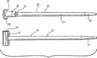
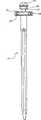
图1是本发明的一种实施方式中的组件的胫骨髓内(IM)杆和股骨IM杆的平面图;1 is a plan view of a tibial intramedullary (IM) rod and a femoral IM rod of an assembly in one embodiment of the invention;
图2是图1中的股骨IM杆的透视图,其被插入股骨中;Figure 2 is a perspective view of the femoral IM rod of Figure 1 inserted into the femur;
图3是图2中示出的股骨IM杆的股骨安装件的剖面图;Fig. 3 is the sectional view of the femoral mount of the femoral IM rod shown in Fig. 2;
图4是图1中的股骨IM杆和胫骨IM杆的透视图,它们分别插入膝关节的股骨和胫骨中;Figure 4 is a perspective view of the femoral IM rod and tibial IM rod of Figure 1 inserted into the femur and tibia, respectively, of the knee joint;
图5是延伸自本发明的组件的拧接螺栓的衬套的透视图,其中,所述拧接螺栓连接至图1的胫骨IM杆;5 is a perspective view of a bushing extending from a screw-on bolt of an assembly of the present invention, wherein the screw-on bolt is connected to the tibial IM rod of FIG. 1 ;
图6是图5的拧接螺栓和本发明的组件的胫骨成角度引导件和弯曲的膝关节切削引导件的平面图;6 is a plan view of the threaded bolt of FIG. 5 and the tibial angulation guide and curved knee cutting guide of the assembly of the present invention;
图7是图5的衬套和IM杆的透视图,其中,拧接螺栓的衬套向前运动以连接IM杆;Figure 7 is a perspective view of the bushing and IM rod of Figure 5, wherein the bushing screwed onto the bolt moves forward to connect the IM rod;
图8是本发明的组件的第一锁定机构的侧视图;Figure 8 is a side view of the first locking mechanism of the assembly of the present invention;
图9是第一锁定机构的透视图,所述第一锁定机构连接至图7的已装配的IM杆和螺栓,其承受所要求负载的扭矩;Figure 9 is a perspective view of the first locking mechanism connected to the assembled IM rod and bolt of Figure 7, which is torqued for the required load;
图10是处于未锁定位置的第一锁定机构的另一个透视图,其装配至图9中的IM杆和螺栓,承受所要求负载的扭矩;Figure 10 is another perspective view of the first locking mechanism in the unlocked position, assembled to the IM rod and bolt of Figure 9, torqued to the required load;
图11是第一锁定机构的另一个透视图,其装配并锁定至图9中的IM杆和拧接螺栓,承受所要求负载的扭矩;Figure 11 is another perspective view of the first locking mechanism, which is assembled and locked to the IM rod and threaded bolt in Figure 9, to withstand the torque of the required load;
图12是本发明的组件的弯曲引导件的支承构件的透视图,其连接至图11的第一锁定机构;Figure 12 is a perspective view of the support member of the curved guide of the assembly of the present invention, connected to the first locking mechanism of Figure 11;
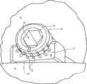
图13是本发明的组件的弯曲膝关节切削引导组件的透视图,其连接至图12的弯曲引导件的支承构件;13 is a perspective view of the flex knee cutting guide assembly of the assembly of the present invention connected to the support member of the flex guide of FIG. 12;
图14是图13的组件的侧视图;Figure 14 is a side view of the assembly of Figure 13;
图15是图13的组件的后视图;Figure 15 is a rear view of the assembly of Figure 13;
图16是图13的弯曲膝关节切削引导组件的快速释放机构的仰视图;16 is a bottom view of the quick release mechanism of the bent knee cutting guide assembly of FIG. 13;
图17是图16的快速释放机构和图12的弯曲引导件的支承构件的透视图;17 is a perspective view of the quick release mechanism of FIG. 16 and the support member of the curved guide of FIG. 12;
图18是图13的弯曲膝关节切削引导组件的弯曲膝关节切削引导件的透视图;18 is a perspective view of a curved knee cutting guide of the curved knee cutting guide assembly of FIG. 13;
图19是本发明的组件的胫骨成角度引导件的正视图,所述胫骨成角度引导件在图1的股骨IM杆和胫骨IM杆之间延伸,连接至拧接螺栓;19 is a front view of the tibial angulation guide of the assembly of the present invention extending between the femoral IM rod and the tibial IM rod of FIG. 1 , connected to a threaded bolt;
图20是图19的IM杆和胫骨成角度引导件的放大视图;Figure 20 is an enlarged view of the IM rod and tibial angulation guide of Figure 19;
图21是图19的IM杆和胫骨成角度引导件的另一个放大视图;Figure 21 is another enlarged view of the IM rod and tibial angulation guide of Figure 19;
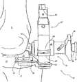
图22是本发明的组件的伸展引导件支承构件和第二锁定机构的透视图,它们装配至图1的股骨IM杆;22 is a perspective view of the extension guide support member and second locking mechanism of the assembly of the present invention, fitted to the femoral IM rod of FIG. 1;
图23是本发明的伸展引导件支承构件装配至图22的第二锁定机构的放大透视图;Figure 23 is an enlarged perspective view of the extension guide support member of the present invention fitted to the second locking mechanism of Figure 22;
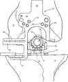
图24—26是本发明的组件的伸展膝关节切削引导件、图22的第二锁定机构和图1的股骨IM杆的透视图,所述伸展膝关节切削引导件附接至伸展引导件支承构件;24-26 are perspective views of the extended knee cutting guide of the assembly of the present invention, the second locking mechanism of FIG. 22, and the femoral IM rod of FIG. 1, the extended knee cutting guide attached to the extended guide support member;
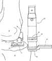
图27所示的透视图示出了当伸展膝关节切削引导件固定至远端股骨的适当位置时,图22的第二锁定机构与图1的股骨IM杆分离的情况;The perspective view shown in Figure 27 shows the second locking mechanism of Figure 22 separated from the femoral IM rod of Figure 1 when the extended knee joint cutting guide is fixed in place on the distal femur;
图28是图24的伸展膝关节切削引导件的正视图;Figure 28 is a front view of the extended knee cutting guide of Figure 24;
图29是图24的伸展膝关节切削引导件的侧视图;29 is a side view of the extended knee cutting guide of FIG. 24;
图30是本发明的组件的L形切削模块的平面图;Figure 30 is a plan view of the L-shaped cutting module of the assembly of the present invention;
图31是图30的L形切削模块的侧视图,所述L形切削模块用于切削股骨的前髁。31 is a side view of the L-shaped cutting block of FIG. 30 used to cut the anterior condyle of the femur.
图32—40示出了本发明的各种可选的模块,所述模块促进快速装配以及有利于使得手术中的使用侵入性最小;Figures 32-40 illustrate various optional modules of the present invention that facilitate rapid assembly and facilitate minimally invasive use in surgery;
图41示出了在本发明的一个实施例中使用的铰接牵开器;和Figure 41 shows an articulating retractor for use in one embodiment of the invention; and
图42示出了本发明用于小型试验的实施例。Figure 42 shows an embodiment of the invention used in a small test.
具体实施方式Detailed ways
下面将参照附图对本发明进行更详细的描述,在附图中,示出的只是本发明的一些实施例,而不是全部实施例。实际上,本发明能够以多种不同的方式实施,不应当认为本发明限于此处所述的实施例,并且,提供这些实施例是使公开的内容符合法定要求。在所有附图中,类似的附图标记表示类似的部件。The invention will now be described in more detail with reference to the accompanying drawings, in which only some, but not all, embodiments of the invention are shown. Indeed, the invention may be embodied in many different ways and should not be construed as limited to the embodiments set forth herein; rather, these embodiments are provided so that this disclosure will comply with statutory requirements. Like reference numerals refer to like parts throughout the drawings.
附图示出了用于利于膝关节的预加工的本发明的组件10,其包括对膝关节的股骨11和胫骨12的切削进行引导定位,以便随后匹配股骨和胫骨膝关节更换部件。通常,组件10包括各种部件(比如一个或多个髓内(IM)杆),它们被选择和设置成,安装在位于膝关节隔间内的参考点,通过膝关节软组织内所限定的相对狭窄的、小的或非侵入性通路而延伸,并且,附接在膝关节外部以选择切除引导件。The figures show an
此处,在预备手术期间,这里使用的解剖方向是参照膝关节的,并且其对应于组件10的示出实施例。然而,取决于膝关节的利手(handedness)情况,或者是个体形态及韧带结构的变化,这些方向可以变化,并且,典型地,不能认为构成限制。Here, the anatomical orientation used here is with reference to the knee joint and corresponds to the illustrated embodiment of the
组件10能够被设置成应用于不同的膝关节弯曲角度,以利于部件在整个弯曲或伸展范围内定位。此处示出的是组件10的部件,它们用于引导在两个不同的弯曲角度下的膝关节的切削和预加工,即90°和完全伸展。然而,部件(或者,在本发明的精神和范围内使用的其他部件)可以被调节或配置成通过相对非侵入性的通道而延伸至处于任何弯曲范围、直至过度弯曲的膝关节(30°,45°,60°,等等,直至过度弯曲)。
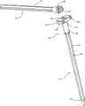
在示出的实施例中,组件10包括两根IM杆,即股骨IM杆13和胫骨IM杆14,它们提供用于支承膝关节弯曲时的组件10的其余部分的参考点,在此情况下是弯曲90°。股骨IM杆13包括股骨安装件15和主轴16,如图1所示。股骨IM杆13的主轴16优选为细长的、相对刚性的轴,当安装时,沿近端、远端方向,所述主轴16在股骨11的IM管内延伸,如图2所示。主轴16可以包括有利于其插入股骨11的结构,如锥形端部17。优选地,主轴16由相对刚性材料制成,比如硬质塑料、不锈钢、钛或其他金属,或者是能够无损地插入骨内且牢固地支承股骨安装件15的材料。In the illustrated embodiment,
股骨安装件15附接至主轴16的远端,与锥形端部17相对。通常,股骨安装件为圆柱形,其轴线垂直于主轴16的长轴延伸。如图3中的股骨安装件的剖视图所示,沿股骨安装件15的轴线限定了中心开口18。中心开口包括两个部分,即:防止旋转的部分,在这种情况下为六边形部分19;以及圆柱形部分20,其允许将组件10的其他部件锁定至股骨安装件15,下面将对其进行更详细的描述。无论如何,一旦股骨IM杆13被安装,则股骨安装件15及其中心开口18优选地在股骨髁之间沿着股骨凹口在前后方向延伸。多个纵向延伸刻度标记21限定在股骨安装件15的外圆柱面上,它们辅助胫骨构件和股骨构件的定位,下面将对其进行更详细的描述。
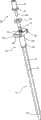
如1和4图所示,胫骨IM杆14包括支承胫骨安装件23的主轴22。类似于股骨IM杆13的主轴16,主轴22具有细长形结构,其远端24逐渐变细,以利于其插入胫骨的IM管。然而,主轴22优选地包括一个或多个凹槽25,所述凹槽25沿着主轴22的长度延伸,以便进一步利于插入,并且防止其在胫骨的IM管内旋转。可选地,主轴16上也可以包括这些凹槽。在主轴22的近端中限定了开口27,其延伸进入凹槽25。这些开口进一步有利于插入胫骨的IM管。和股骨IM杆13的主轴16一样,主轴22可以由相对刚性的多种材料制成,以便为胫骨安装件23提供牢固的支承。As shown in FIGS. 1 and 4 , the
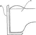
包括在胫骨安装件23内的是增厚的圆柱形部分26和平台凸缘28,如图4所示。优选地,圆柱形部分26的尺寸适合于胫骨12的IM管。圆柱形部分在其远端连接至主轴22,在其近端支承平台凸缘28。平台凸缘垂直于圆柱形部分26向外延伸,并且具有三个平坦侧面和一个新月形侧面。新月形侧面断开,以在切除近端胫骨之前为前十字韧带提供空间。平坦侧面可以进一步辅助引导定位和切削,比如在单髁关节成形过程中胫骨隔间切除期间,其中,只重建单个髁和胫骨坪的一部分。Included within the
带螺纹的开口29延伸进入胫骨安装件23,并且提供用于弯曲螺栓30的耦联连接,所述弯曲螺栓30包括螺纹轴31、六边形凸缘32和衬套33,如图5和6所示。螺纹轴31具有多个螺纹,并且延伸远离六边形凸缘32,同时,衬套33是平滑的圆柱形轴,其从六边形凸缘32的另一侧与螺纹轴相对地延伸。六边形凸缘32被成形为允许通过旋紧装置或者其他扳手旋紧,以提供用于使螺纹轴32前进的动力。A threaded
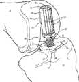
螺纹轴31被设置成向前进入胫骨安装件23的带螺纹的开口29,直到它与平台凸缘28齐平,因此将衬套33定位在其最低的断面位置,如图5所示。这些位置允许股骨11和股骨安装件15由此延伸并滑入至位于衬套33上方的位置。然后,扭矩扳手用于使螺纹轴31的运动反向,直到衬套33接合股骨安装件15内的中心开口18的圆柱形部分20,如图7所示。一直反向旋转,直到在扭矩扳手上获得预先选择的扭矩测量值,或者是获得韧带结构的足够的拉伸。一旦获得适当的韧带拉伸,那么记录此扭矩,以在此后的方法中进行比较。最后形成的组件仿真了膝关节弯曲时股骨和胫骨的静态连接关系(例如弯曲30°,60°或90°,或者更多),如下所述,外科医生可以以此作为后续切除器具的参考。The threaded
包括在组件10内的还有快速连接锁定机构34,其连接进入中心开口18的六边形部分19,如图8和9所示。包括在此锁定机构的实施例中的是静态支架臂35、弹簧偏置柱塞36和静态锁定延伸部分37,所述静态锁定延伸部分37仿真了防旋转特征19,并且,在这种情况下,其具有六边形形状。臂35具有细长形部分38和圆头部分39。臂35的细长形部分38具有方形断面,并且延伸自圆头部分39,所述圆头部分39具有部分呈圆柱形的形状,在其端部具有两个相对的平面。延伸自圆头部分的一个平面的是六边形延伸部分37。六边形延伸部分37具有六边形剖面,其被设置成与限定在股骨安装件15内的中心开口18的六边形部分19紧密地配合。如图8所示,限定在头部39的一个圆形表面内的是呈螺旋形延伸的狭槽43,如下所述,其引导柱塞36的运动。Also included in the
通过圆头部分39和六边形延伸部分37限定的是圆筒形开口40,柱塞36从中延伸通过。具体地,柱塞36包括揿钮41、轴42、弹簧45和旋转延伸部分44,旋转延伸部分44仿真了防旋转特征37,在这种情况下是六边形,但是,其可以是非圆柱形的,诸如能够限制旋转的正方形、三角形或者椭圆形。揿钮41位于柱塞36的一端,并且为圆盘形,其具有隆起物以有利于用拇指按压。位于揿钮41下的是弹簧45,其优选为圈簧,并且环绕轴42延伸,并且位于揿钮和头部分39之间,以便将它们偏置分开。Defined by the
轴42包括销46,其垂直于轴延伸,并且进入头部39内限定的螺旋状狭槽43,如图8所示。因此,揿钮41的按压使轴42在头部39的开口40内向前运动,并且还因为安装在其上的销46呈螺旋形地在螺旋状狭槽43内移动而导致轴的旋转。柱塞36的六边形端部44被固定至轴42的与揿钮41相对的端部,沿着六边形延伸部分37的自由端延伸,并且具有六边形形状,其大小与六边形延伸部分37相匹配。
由于连接至轴42,所以揿钮41的按压还引起柱塞36的六边形端部44的旋转,直到六边形端部的平面匹配六边形延伸部分37的平面方向,如图10所示。匹配此方向允许六边形延伸部分37和六边形端部44插入股骨安装件15的中心开口18的六边形部分19,如图11所示。一旦揿钮41释放,那么弹簧45向上偏置揿钮、轴42和六边形端部44,使得六边形端部的平面回到其相对于六边形延伸部分37的平面的非匹配、错开位置(如图9所示)。Due to the connection to the
就此,柱塞36的六边形端部44位于中心开口18的圆柱形部分20内,并且,由于其处于非匹配位置,所以其不能通过中心开口的六边形部分19缩回。因此,锁定机构34变得可旋转可移动地相对于股骨安装件15和股骨IM杆13锁定。一旦锁定在适当位置,锁定机构34的臂35自股骨11的髁和股骨安装件15向外向前延伸。特别地,相对狭窄的股骨安装件15和狭窄细长形结构的臂35的组合允许通过相对小的手术通路开口,有利于以较少的侵入性步骤使用组件10。例如,可以利用改变的中股肌、内侧中股肌或者下股肌通路而进行8—10厘米的小切口,其能避免四头肌从前胫骨松弛。In this regard, the
本发明示出实施例的组件10中还包括弯曲引导件的支承构件47,其通过锁定机构34来支承。弯曲引导件的支承构件包括滑动器构件48和棘齿条49。滑动器构件限定矩形开口50,其大小与形状允许滑动器构件通过锁定机构34的臂35的矩形剖面支承,并沿着该剖面滑动。这些运动允许附接至滑动器构件48的棘齿条49移向和远离膝关节。优选地,滑动器构件48被成形为具有抓握部分(例如,所示滑动器构件的渐缩部分),并且还可以包括某种销或者锁定组件,以阻止但不禁止其相对于臂35滑动。棘齿条49本身在剖面图中也是矩形,并且当装配时,其从锁定机构34的臂35处向远端延伸,如图12所示。棘齿条49还包括一对倒角,其支承多个邻近的棘爪凹槽51,棘爪凹槽51沿着棘齿条的长度延伸。Also included in the
组件10还包括弯曲膝关节切削引导组件52,其附接至弯曲引导件的支承构件47,如图13、14和15所示。弯曲膝关节切削引导组件52包括快速释放机构53和切削引导件54。快速释放机构53包括主体55、牵引销56、第一和第二弹簧57、58、锁定杆59和锁销60。如图16所示,主体55限定矩形开口61,其允许主体滑动在棘齿条49的矩形剖面之上。另外,主体55包括侧开口,牵引销56穿入侧开口中延伸,以致其端部与棘爪凹槽51接合。具体地,第一弹簧57偏置牵引销至通常接合棘爪凹槽的位置,以便锁定牵引销,并且,主体55进入滑动器构件48上的特殊位置。锁销60延伸贯穿主体并通过牵引销56以固定牵引销56并防止它脱离。The
另外,主体55包括U形夹62,其自主体的与牵引销56相对的一侧向外延伸,并在其中间部分附近支承锁定杆59的旋转。同样,如图17所示,锁定杆具有曲线抓握部分,其被第二弹簧58从主体55向外偏置,锁定杆的相对端部包括渐细楔片63,其接合切削引导件54以便锁定快速释放机构53,如下所述。远离U形夹62延伸的是主体55的接合部件64,其与锁定杆相对。接合部件64具有矩形的剖面,并且,在如图13所示的装配条件下,延伸成与切削引导件54相连。In addition, the
如图13所示,切削引导件54从快速释放机构53向后(当装配时)延伸,并且包括安装件65、K缆引导或固定销部分66、横钉部分71、近端胫骨切削引导部分67和后关节股骨切削引导部分68。安装件65限定矩形开口69,其大小与形状被设置成可滑动地容纳快速释放机构53的主体55的接合部件64。安装件65还在矩形开口69的一个侧壁内限定凹口70,如图18所示。当锁定杆处于第二弹簧58的偏置作用下时,凹口70的尺寸、形状和位置要能容纳锁定杆59的渐细楔片63,如图15所示。通过压下锁定杆59的自由端、克服第二弹簧58的偏置并使得安装件65的凹口70与渐细楔片脱离,便能容易地完成切削引导件54的释放。As shown in FIG. 13 , cutting
固定销(或K缆)引导部分66、胫骨切削引导部分67和股骨切削引导部分68都具有新月形状,其环绕前中或前侧胫骨(取决于需要哪种切削)的生理弯曲部分沿中间—横向方向延伸,如图13所示。固定销引导部分66与安装件65相邻,并限定多个固定销孔72,固定销孔72向后呈一定角度延伸,以便引导固定销(用于在组件10的其他部件释放之前固定切削引导件54)进入胫骨12上的皮层骨的最厚的前部。虽然不是最优选,但是,固定销孔的数量和方向可取决于所需连接的牢固程度、胫骨12的尺寸和形态等而改变。Pin (or K-cable)
胫骨切削引导部分67被定位成与固定销引导部分66相邻,并限定用于引导胫骨切削的狭槽。狭槽沿着引导部分67的新月形状的长度方向延伸,其定向通常相对于胫骨坪而平行。然而,由引导部分67限定的切除平面在后坡面内(径向平面角度)和内翻/外翻(冠状面角度)方面会有变化,这取决于所需的位置和外科医生对切削引导件54的偏好。图19示出了这种切削的实例,其中,胫骨具有平坦平面切削,其在胫骨12的近端的前-后面和中间侧面中延伸。股骨切削引导部分68通过一对连接凸缘73与胫骨切削引导部分67近端地间隔开,以便桥接膝关节隔间。类似于胫骨切削引导部分67,股骨切削引导部分68限定狭槽,所述狭槽沿着新月形的长度方向延伸。然而,因为膝关节弯曲,所以切削被引导通过股骨11的髁的后面。Tibial cutting
用于在膝关节弯曲时定位切削的组件10的部件的优点是,相对来说,它们能够非侵入性地、狭小地切削膝关节的前部软组织(其中髌骨是缩回的),所述部件包括股骨安装件15、胫骨安装件23、弯曲螺栓30、锁定机构34、弯曲引导件的支承构件47和弯曲膝关节切削引导组件52。通常,从图14和15中可以看出,用于在膝关节弯曲时进行切削的组装的部件相对狭窄,因为它们呈U形从关节空间延伸出来,同时为支承切削引导件54提供了坚固的连接,并提供了部件的快速装配和拆卸以及弯曲膝关节切削引导件的精确定位。只考虑切削引导件54(其可以定位在囊状切口的内部),此部件的宽度小于传统的切削引导件,例如,大致为4至5厘米的范围,因此允许它们以具有最小侵入性的方式接近膝关节。An advantage of the components of
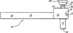
组件10还包括被设置成在膝关节伸展时引导切削的工具(即,胫骨和股骨通常对准,或者弯曲的角度为0°),如图19—29所示。对于膝关节的伸展来说,股骨IM杆13和胫骨IM杆14两者保持在适当位置,如图19所示。然而,不是胫骨安装件23连接至胫骨IM杆14,而是胫骨成角度引导件74附接至胫骨IM杆。胫骨成角度引导件74包括量块76和支柱97,所述支柱97装配在拧接螺栓96中(类似于弯曲螺栓30,但是没有衬套33)。拧接螺栓96同样具有六边形凸缘75。可选地,单独的量块76可以与轴(如图6所示)一同使用,所述轴延伸进入衬套33内的开口,以避免螺栓30的释放。The
无论如何,当拧接螺栓96的螺纹轴延伸进带螺纹的开口29并且限定弧形表面77和多个刻度标记78时,量块76自胫骨安装件23的平台凸缘28向上延伸,其中所述刻度标记78限定在螺纹轴前表面上,如图19—21所示。弧形表面77的形状和尺寸被设置成容纳圆柱形的股骨安装件15的外表面,并且允许股骨安装件15沿内翻、外翻方向上旋转并且沿前、后方向滑动。这些运动是自由的,以便不对股骨11和胫骨12造成过度约束,而且仍然有助于器具的前、后对准以及旋转位置的选择,以获得胫骨和股骨切削的更佳定位。股骨安装件15和胫骨成角度引导件74的形状的其他变化及组合可以用于允许这些关节活动范围,比如通过使量块76(其为圆柱形)和股骨安装件15(其为弧形状)的形状互换,通过在两个平面之间设置圆形,远离器具组件延伸弯曲读数装置等,并且,它们仍然处于本发明的范围之内。Regardless, the
类似于在弯曲位置中采用的技术,通过利用扭矩扳手调节拧接螺栓96的六边形凸缘75的旋转,完成股骨11和胫骨12的相对近端-远端的定位。此运动使胫骨拧接螺栓96的螺纹轴进入胫骨安装件23中的带螺纹的开口29或从中退出,并且使胫骨成角度引导件74朝向股骨安装件15向前运动。优选地,股骨11和胫骨12分开,直到扭矩扳手具有类似于膝关节弯曲时具有的读数值,以确保在膝关节伸展时关节没有过于绷紧。关于扭矩扳手和关节间隙的大小,扭矩扳手可以装备有延长器,所述延长器延伸扳手的长度,在其端部具有六边形狭口(jaw),并且具有相对较薄的低断面。如果是这样,那么可以调节扭矩测量,以补偿延长器的附加长度。在以上两种情况下,目的都是匹配在器具结构强制膝关节以某种程度弯曲时而获得的扭矩值,在这种情况下是弯曲90°或者更大角度,其目的还是将螺栓旋转至类似的扭矩测量值,所述扭矩测量值为在早期阶段扭矩扳手上达到的扭矩值,或者,旋转螺栓直到韧带结构获得足够的拉伸。Relative proximal-distal positioning of the
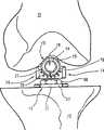
再次参照图20和21,量块76的刻度标记78从股骨安装件15的转动中心向外辐射,起始于股骨安装件的外表面,并位于量块的前表面上。量块76的刻度标记78被设置成与股骨安装件15(如图箭头所示)的刻度标记21相匹配,用于指示胫骨12相对于股骨11的外翻角度。通常,外翻角度应在3至7度范围内,或者甚至是2至9度范围内,这取决于膝关节的生理结构、外科医生的偏好等等。Referring again to FIGS. 20 and 21 , graduated
一旦相对于股骨11而调节了胫骨12的角度和近端远端定位,那么,利用第二锁定机构84将伸展引导件支承构件79附接至股骨安装件15,如图22和23所示。通常,第二锁定机构84包括柱塞36(其部件包括六边形端部44)、六边形延伸部分37和螺旋状狭槽43,它们的数量大体相同,因为它们与第一锁定机构34的同样部件承担同样的功能。第二锁定机构84的不同之处在于,其头部39更长、呈圆柱形,并且缺少臂35的细长形部分38。此外,第二锁定机构84包括与柱塞36相邻定位的夹紧凸缘86,当压下柱塞时,其有利于抓握。无论如何,六边形端部44具有同样的旋转运动,其有利于第二锁定机构84的端部与股骨安装件15的快速连接。Once the angulation and proximal-distal positioning of the
伸展引导件支承构件79包括安装件80、支承臂81和固定凸缘82。安装件80具有圆柱形并具有从中延伸的圆筒形开口83,其被设置成可滑动地容纳第二锁定机构84,但不受所述第二锁定机构84的旋转约束。从安装件80的一侧延伸出来的是支承臂81,其为具有T形剖面的细长形结构。从安装件80的另一侧延伸出来的是辅助凸缘82,其用作机构的壳体,在此情况下,所述机构为球和弹簧85,以便对于伸展引导件支承构件79的相对于第二锁定机构84的旋转提供一些阻力。The extension
在组件10的示出实施例中还包括伸展膝关节切削引导件87,其在定位期间由伸展引导件支承构件79支承,如图24—29所示。伸展膝关节切削引导件87包括安装件88、固定销(或者K缆)引导部分89、股骨切削引导部分90和参考杆91。安装件88通常处于伸展膝关节切削引导件87的主体部分的中心,并限定通道92,该通道具有与支承臂81的T形剖面相匹配的横截面形状。匹配的形状允许伸展膝关节切削引导件87在近端-远端方向上沿着支承臂81滑动。Also included in the illustrated embodiment of the
固定销引导部分89限定多个K缆孔93(或者其他类型的紧固件,例如,螺栓、钉子等),在伸展膝关节切削引导件87被定位之后,所述孔93允许利用固定销进行固定。当被定位时,孔93位于前股骨的内侧和外侧上,以便允许固定至相对较厚的皮层骨,如图25所示。由于具有K缆孔72,K缆孔93可以朝向各种角度,或者被选择性地定位成将紧固件引导进入股骨11上的密质骨并使其通过更长的长度。Fixed
股骨切削引导部分90向外或向内延伸,用于重建一致的隔间(如示出的实施例),或者同时在两个方向上延伸,用于完全切除股骨髁。特别地,当伸展膝关节切削引导件87位于适当位置(如图29所示)时,引导部分90以U形向远端延伸,所述引导部分环绕第二锁定机构84。无论如何,引导部分90从K缆引导部分89向远端延伸,然后向外或向内延伸以限定导槽94。导槽94具有足够的宽度,以允许切削工具或刀刃通过,但同时仍促进相对较直或较平的切除。特别地,向内延伸允许通过向内定向地接近膝关节隔间而避免膝盖骨向外移动。The femoral
自股骨切削引导部分90进一步向远端延伸的是伸展膝关节切削引导件87的一部分,该部分限定了可旋转支承参考杆91的U形夹95。参考杆向外或向内延伸并沿前后方向旋转,以允许定位在关节分隔间内,如图24和25所示。参考杆91具有宽的、平坦的远端面,其被设置成抵靠在平坦胫骨切口上,并且,平坦的外侧面被设置成与平台凸缘28的侧面邻接。这些表面阻止了伸展膝关节切削引导件87沿着伸展引导件支承构件79的支承臂81的远端运动。由于参考杆91和第二锁定机构84在适当的位置,所以固定销可以通过销孔93插入引导部分89,以将股骨切削引导部分90固定至股骨11。这样允许伸展引导件支承构件79的拆卸,如图27、28和29所示。Extending further distally from femoral cutting
有利地,用于在膝关节伸展时定位切削的部件包括拧接螺栓96、胫骨成角度引导件74、伸展引导件支承构件79和伸展膝关节切削引导件87,由于部件较窄的宽度和侧面,它们被配置成通过向前和向内靠近膝关节分隔间而穿过。例如,如图25所示,第二锁定机构84的后部以及参考杆91将通过切口,并且具有上述的狭窄度和低剖面。优选地,此部件的宽度小于传统切削引导件,例如,大致为4至5厘米的范围,因此允许它们以具有最小侵入性的方式接近膝关节。Advantageously, the components used to position the cut while the knee is in extension include the threaded
在此初始切削后,进而利用初始切削作为参考而进行进一步的切削。如图30和31所示,L形板99被用于与股骨11的后远端平面邻接,以引导前面的切削。可以利用倒棱模块进行倒角切削(前面的和后面的),其他精切削可以参考利用本发明的组件10进行的初始切削。这些精切削的其他描述可以2004年3月5日提交的美国专利申请10/794,188中找到,其标题是“Reference Mark Adjustment Mechanism fora Femoral Caliper and Method ofUsing the Same(用于股骨夹持的参考标记调整装置以及使用所述装置的方法)”,通过参考方式将其合并与此。After this initial cut, further cuts are made using the initial cut as a reference. As shown in Figures 30 and 31, an L-shaped plate 99 is used to abut the posterior distal plane of the
在本发明的另一个实施例中,如图32至40所示,组件10包括附加模块选项以促进更快的装配。如图32所示,股骨IM杆13包括第二股骨安装件100。第二股骨安装件100为鞍形或新月形,其从中心连接物向外和向远端延伸至股骨IM杆13的主轴16的远端。开口101限定在鞍的内侧(凸曲面),其被设置成容纳支承股骨安装件15的股骨安装杆102,如图33所示。In another embodiment of the present invention, as shown in FIGS. 32-40, the
再次参照图32,胫骨IM杆14包括由轴22支承的胫骨安装件23的改型。具体地,胫骨安装件23的平台凸缘28具有加宽的矩形形状,其从带螺纹的开口29向外横向延伸。一对引导安装开口103限定在平台凸缘28的前侧,引导安装开口103向后延伸进入平台凸缘。如图34所示,通过提供用于安装衬套33的支柱104以及位于中心开口内的六边形凸缘32,弯曲螺栓30也可以进一步模块化,所述中心开口限定在六角螺栓105内,所述六角头螺栓105包括从其顶部105延伸的螺纹轴31。图35和36示出了股骨安装件15和胫骨安装件32的组装,以及通过升高六角头螺栓105进行张紧度调节。Referring again to FIG. 32 , the
如图37所示,组件10还包括弯曲膝关节切削引导组件52,其包括弯曲膝关节切削引导件54和直接安装件106。直接安装件包括两根柱107,它们是隔开的并且延伸自安装块108。柱107的间隔和尺寸被设置成延伸进入引导安装开口103,所述引导安装开口103限定在平台凸缘28内。安装块108可以连接至胫骨安装件32,如通过密封的磁铁111。弯曲膝关节切削引导件54附接至安装块108并从安装块向远端延伸。弯曲膝关节切削引导件限定狭槽109的选择,以用于引导胫骨和股骨的切削。As shown in FIG. 37 , the
后股骨切削可以这样实现,即,通过使弯曲膝关节切削引导组件52上下运动实现,或通过利用可以是上下运动的切削引导组件52的变型的另一模块实现,其中,切削引导件54和狭槽109的选择朝向支柱107移动,因此更靠近膝关节的后股骨髁。切削引导组件52的狭槽109的选择可以是如图所示,狭槽附接在中心,或者,可以在中心开口并且沿着切削引导件54的两侧附接。Posterior femur cutting can be realized like this, realize by making bending knee joint cutting
如图38和39所示,胫骨IM杆14包括外翻适配器部件110或者股骨安装件15的改型,其自身具有被设置成插入六角头螺栓105的中心开口内的柱。如图40所示,外翻适配器部件110呈凸形,其被设置成延伸进入凹形的第二股骨安装件100。当膝关节伸展时,此匹配允许在内翻-外翻(varus-valgus)角度定位切削,类似于如上所述的第一实施例。通过支柱107,类似于弯曲膝关节切削引导件,可以安装伸展膝关节切削引导件。As shown in FIGS. 38 and 39 , the
本发明的组件10具有许多优点。其提供了锁定部件的相对狭窄、低剖面的组合,所述锁定部件将切削引导件可靠地附接至胫骨IM杆和/或股骨IM杆。这为对胫骨和股骨的参考切削提供了可靠的引导,其中减小了接近关节的侵入性。进一步地,诸如第一和第二锁定机构34、84和快速释放机构53的许多部件有利于快速装配、容易调节以及快速拆卸,从而提高了效率。通过利用螺栓30和96或者105以及胫骨成角度引导件74或者外翻适配器部件110,允许在弯曲和伸展过程中,使得胫骨和股骨在匹配量的扭矩作用下分开,从而确保在整个弯曲范围内胫骨和股骨的膝关节替换部件的更佳的配合。此外,胫骨成角度引导件允许外科医生根据需要调整胫骨的外翻角度量,以与患者的生理结构相匹配。The
如图41所示,在本发明的另一个实施例中,改进的股骨安装杆102和股骨安装件15能够与牵开器杆一同使用,股骨安装件15具有将安装件15附接至股骨安装杆102的铰链机构,所述牵开器杆穿过股骨安装件15内的孔18被放置且被向后引导至胫骨,因此为牵开器提供支点和杠杆臂,从而使胫骨向前运动或向前方运动,以允许其暴露出来,以便在完成骨切削后放置整个膝关节成形的胫骨构件。由于IM杆刚性地安装至骨头,所以在膝关节手术期间,其他的牵开器也可附接至引导组件以有利于膝关节暴露出来。As shown in FIG. 41, in another embodiment of the present invention, a modified femoral mounting rod 102 and a
如图42所示,在本发明的另一个实施例中,在实际的最后膝关节成形移植物放置之前,小型试验部件或如下的试验部件可用于检查对准情况以及韧带的稳定性,所述试验部件更小但被成形为具有与实际膝关节成形移植物相同的厚度和半径,目的是装配在股骨IM杆13的孔101和胫骨IM杆14的孔29中,并且铰接在膝关节的中央部分。此对中设置的小型膝关节成形移植物的系统可以是独立的整个膝关节成形。本发明该实施例的一个优点是,较小器具占据更少的空间。小型试验用股骨构件可以被设计成具有切削表面或者狭槽,用于倒角切削及其他精切削,因此省去了对图30和31示出的倒角切削模块和L板99的需求。As shown in Figure 42, in another embodiment of the present invention, prior to the actual final knee arthroplasty graft placement, a small trial part, or trial part as follows, can be used to check the alignment and stability of the ligaments, The trial part is smaller but shaped to have the same thickness and radius as the actual knee arthroplasty graft and is intended to fit in the
在另一个实施例中,因为引导组件刚性地安装至骨头上并在膝关节预加工的主要步骤期间留在适当位置,所以,计算机辅助引导件被附连至引导组件器具,因此有利于计算机辅助的整个膝关节置换。In another embodiment, the computer-aided guide is attached to the guide assembly tool, thereby facilitating computer-aided guidance because the guide assembly is rigidly mounted to the bone and remains in place during the major steps of knee preparation. total knee replacement.
在一些实施例中,引导组件器具可以进行变化,以与短IM杆或者胫骨平台一起使用,取代用于髓外膝关节预加工的IM杆。In some embodiments, the guide assembly instrument may be modified for use with a short IM rod or tibial plateau instead of an IM rod for extramedullary knee preparation.
在一些实施例中,引导组件将患者的腿保持在适当的位置。这样减小了对用于握住患者腿的医疗辅助的需要。In some embodiments, the guide assembly holds the patient's leg in place. This reduces the need for medical assistance to hold the patient's leg.
本领域的技术人员可以理解,此处公开的本发明可以进行许多变化并具有其他实施例,它们具有上面的描述以及附图中公开的技术的优点。因此,应当理解,本发明并不限于公开的特定实施例,并且,变化以及其他实施例应当处于所附权利要求的范围之内。虽然此处使用了专用名词,但是,它们只是一般意义的描述,并不是用于限制的目的。Those skilled in the art will appreciate that the invention disclosed herein is capable of many changes and other embodiments which have the advantages of the techniques disclosed in the above description and accompanying drawings. Therefore, it is to be understood that the inventions are not to be limited to the particular embodiments disclosed and that modifications and other embodiments are intended to be within the scope of the appended claims. Although terminology is used herein, they are descriptive in a general sense only and not for purposes of limitation.
Claims (34)
Applications Claiming Priority (3)
| Application Number | Priority Date | Filing Date | Title |
|---|---|---|---|
| US11/349,772US7927336B2 (en) | 2005-02-08 | 2006-02-08 | Guide assembly for guiding cuts to a femur and tibia during a knee arthroplasty |
| US11/349,772 | 2006-02-08 | ||
| PCT/US2007/003552WO2007092614A2 (en) | 2006-02-08 | 2007-02-08 | Guide assembly for guiding cuts to a femur and tibia during a knee arthroplasty |
Publications (2)
| Publication Number | Publication Date |
|---|---|
| CN101420915A CN101420915A (en) | 2009-04-29 |
| CN101420915Btrue CN101420915B (en) | 2012-07-04 |
Family
ID=38345838
Family Applications (1)
| Application Number | Title | Priority Date | Filing Date |
|---|---|---|---|
| CN2007800126703AExpired - Fee RelatedCN101420915B (en) | 2006-02-08 | 2007-02-08 | Guide assembly for guiding cuts of the femur and tibia during knee arthroplasty |
Country Status (9)
| Country | Link |
|---|---|
| US (1) | US7927336B2 (en) |
| EP (1) | EP1986555B1 (en) |
| JP (3) | JP5312047B2 (en) |
| KR (7) | KR101499377B1 (en) |
| CN (1) | CN101420915B (en) |
| AU (4) | AU2007212265B2 (en) |
| CA (2) | CA2916743A1 (en) |
| DK (1) | DK1986555T3 (en) |
| WO (1) | WO2007092614A2 (en) |
Cited By (1)
| Publication number | Priority date | Publication date | Assignee | Title |
|---|---|---|---|---|
| TWI617282B (en)* | 2016-12-08 | 2018-03-11 | 國立成功大學 | Bone-cutting aided tool and operation method thereof |
Families Citing this family (65)
| Publication number | Priority date | Publication date | Assignee | Title |
|---|---|---|---|---|
| US7094241B2 (en) | 2002-11-27 | 2006-08-22 | Zimmer Technology, Inc. | Method and apparatus for achieving correct limb alignment in unicondylar knee arthroplasty |
| US7641661B2 (en) | 2003-12-26 | 2010-01-05 | Zimmer Technology, Inc. | Adjustable resection guide |
| US8167888B2 (en)* | 2004-08-06 | 2012-05-01 | Zimmer Technology, Inc. | Tibial spacer blocks and femoral cutting guide |
| US8303597B2 (en) | 2005-02-08 | 2012-11-06 | Rasmussen G Lynn | Systems and methods for guiding cuts to a femur and tibia during a knee arthroplasty |
| US8317797B2 (en) | 2005-02-08 | 2012-11-27 | Rasmussen G Lynn | Arthroplasty systems and methods for optimally aligning and tensioning a knee prosthesis |
| US7927336B2 (en) | 2005-02-08 | 2011-04-19 | Rasmussen G Lynn | Guide assembly for guiding cuts to a femur and tibia during a knee arthroplasty |
| US7780671B2 (en)* | 2006-01-23 | 2010-08-24 | Zimmer Technology, Inc. | Bone resection apparatus and method for knee surgery |
| CA2648444C (en)* | 2006-04-04 | 2014-03-18 | Smith & Nephew, Inc. | Trial coupler systems and methods |
| GB2445620B (en)* | 2007-01-13 | 2011-10-26 | Derek James Wallace Mcminn | Instrumentation for knee surgery |
| US20090018544A1 (en)* | 2007-07-13 | 2009-01-15 | Zimmer, Inc. | Method and apparatus for soft tissue balancing |
| US8226658B2 (en)* | 2008-05-09 | 2012-07-24 | Depuy Products, Inc. | Instrument for guiding resection of a greater tubercle |
| KR101973101B1 (en)* | 2009-05-29 | 2019-04-26 | 스미스 앤드 네퓨, 인크. | Methods and apparatus for performing knee arthroplasty |
| US8900316B2 (en) | 2010-01-29 | 2014-12-02 | Smith & Nephew, Inc. | Cruciate-retaining knee prosthesis |
| US8974459B1 (en) | 2010-05-21 | 2015-03-10 | Howmedica Osteonics Corp. | Natural alignment knee instruments |
| USD651314S1 (en)* | 2010-05-28 | 2011-12-27 | Zimmer, Inc. | Extramedullary modular post |
| USD651313S1 (en)* | 2010-05-28 | 2011-12-27 | Zimmer, Inc. | Extramedullary telescoping tube |
| USD651317S1 (en)* | 2010-06-04 | 2011-12-27 | Zimmer, Inc. | Femoral prosthesis sizing tool |
| CN101884560B (en)* | 2010-06-04 | 2012-02-29 | 王岩 | Universal-type femur external rotation osteotomy guider |
| US8672946B2 (en) | 2011-02-11 | 2014-03-18 | Biomet Manfacturing, LLC | Method and apparatus for performing knee arthroplasty |
| EP2596757B1 (en)* | 2011-11-23 | 2014-07-16 | Waldemar Link GmbH & Co. KG | Device for setting a cut level for bone resection |
| ES2656974T3 (en) | 2012-01-19 | 2018-03-01 | Stryker European Holdings I, Llc | Cuff for suprarrotulian surgery |
| US9549742B2 (en) | 2012-05-18 | 2017-01-24 | OrthAlign, Inc. | Devices and methods for knee arthroplasty |
| JP6010794B2 (en)* | 2012-07-18 | 2016-10-19 | バイオメット・ジャパン株式会社 | Surgical jig |
| CN104955421A (en) | 2012-10-18 | 2015-09-30 | 史密夫和内修有限公司 | Alignment devices and methods |
| US9949837B2 (en) | 2013-03-07 | 2018-04-24 | Howmedica Osteonics Corp. | Partially porous bone implant keel |
| JP6502214B2 (en)* | 2014-08-29 | 2019-04-17 | 京セラ株式会社 | Artificial joint surgery instrument |
| KR101675581B1 (en) | 2015-01-21 | 2016-11-14 | 고용곤 | Pin Insert Guide Module Having Bridge Structure For Total Knee Arthroplasty, and Manufacturing Method Thereof |
| KR101675584B1 (en) | 2015-01-21 | 2016-11-14 | 고용곤 | Pin Insert Guide Module Having Alignment Rod For Total Knee Arthroplasty, and Manufacturing Method Thereof |
| DE102016204307B3 (en)* | 2016-03-16 | 2017-07-20 | Carsten Boos | Operating device for a human knee operation |
| KR101779920B1 (en)* | 2016-03-29 | 2017-09-21 | 주식회사 코렌텍 | Tibial resection guide combination assembly |
| US10299847B2 (en) | 2016-09-22 | 2019-05-28 | Globus Medical, Inc. | Systems and methods for intramedullary nail implantation |
| US10492803B2 (en) | 2016-09-22 | 2019-12-03 | Globus Medical, Inc. | Systems and methods for intramedullary nail implantation |
| US10751096B2 (en) | 2016-09-22 | 2020-08-25 | Bala Sundararajan | Systems and methods for intramedullary nail implantation |
| US11045242B2 (en) | 2016-09-22 | 2021-06-29 | Globus Medical, Inc. | Systems and methods for intramedullary nail implantation |
| US11083503B2 (en) | 2016-09-22 | 2021-08-10 | Globus Medical, Inc. | Systems and methods for intramedullary nail implantation |
| JP2020500600A (en)* | 2016-11-30 | 2020-01-16 | ジー リン ラスムッセン | System and method for providing a tibial baseplate |
| US12414862B2 (en) | 2016-11-30 | 2025-09-16 | G. Lynn Rasmussen | Systems and methods for providing a tibial baseplate system |
| US11185425B2 (en) | 2016-12-22 | 2021-11-30 | Orthosensor Inc. | Surgical tensor configured to distribute loading through at least two pivot points |
| US10772641B2 (en) | 2016-12-22 | 2020-09-15 | Orthosensor Inc. | Surgical apparatus having a frame and moving support structure and method therefore |
| US11266512B2 (en) | 2016-12-22 | 2022-03-08 | Orthosensor Inc. | Surgical apparatus to support installation of a prosthetic component and method therefore |
| US11284873B2 (en) | 2016-12-22 | 2022-03-29 | Orthosensor Inc. | Surgical tensor where each distraction mechanism is supported and aligned by at least two guide shafts |
| US11291437B2 (en) | 2016-12-22 | 2022-04-05 | Orthosensor Inc. | Tilting surgical tensor to support at least one bone cut |
| CA3056495A1 (en) | 2017-03-14 | 2018-09-20 | OrthAlign, Inc. | Soft tissue measurement & balancing systems and methods |
| AU2018272057B2 (en) | 2017-05-26 | 2024-02-08 | Stryker Corporation | Bone mill with an accessible milling element |
| EP3409218A1 (en)* | 2017-05-30 | 2018-12-05 | Samo S.p.A. | Jig for use in knee replacement surgery |
| KR102053600B1 (en)* | 2017-07-25 | 2019-12-11 | 주식회사 코렌텍 | Patient-Specific Artificial Shoulder Joint Surgical Instruments |
| JP6998393B2 (en)* | 2017-07-28 | 2022-02-04 | ライト メディカル テクノロジー インコーポレイテッド | Joint osteotomy system and method |
| KR102019889B1 (en) | 2017-08-24 | 2019-09-10 | 주식회사 코렌텍 | Smart surgical instruments for artificial joint replacement |
| WO2019046518A2 (en)* | 2017-08-31 | 2019-03-07 | Smith & Nephew, Inc. | Cutting guide and method |
| US10835262B2 (en) | 2017-12-06 | 2020-11-17 | Howmedica Osteonics Corp. | Tibial posterior slope alignment guide |
| AU2018389760B2 (en)* | 2017-12-22 | 2021-03-25 | Medacta International Sa | Cutting guide for periacetabular osteotomy and kit for periacetabular osteotomy |
| CN109044479A (en)* | 2018-09-03 | 2018-12-21 | 孙旗 | Scroll saw guide device, spinal lamina cutting method and spinal nerve root anatomic method |
| KR102143842B1 (en) | 2018-09-13 | 2020-08-12 | 주식회사 셀루메드 | Drilling Guide Apparatus For Total Knee Arthroplasty |
| DE102018130119A1 (en)* | 2018-11-28 | 2020-05-28 | Aesculap Ag | Fixation system and alignment device |
| DE102018130117A1 (en) | 2018-11-28 | 2020-05-28 | Aesculap Ag | Fixing bracket and alignment device |
| CN109431560B (en)* | 2018-12-12 | 2020-08-21 | 南昌大学第二附属医院 | Posterior lumbar surgery distraction device |
| DE102019103880A1 (en) | 2019-02-15 | 2020-08-20 | Aesculap Ag | Fixation bracket and alignment device |
| US11633219B2 (en) | 2019-06-26 | 2023-04-25 | Globus Medical, Inc. | Fenestrated pedicle nail |
| US20210228377A1 (en) | 2020-01-29 | 2021-07-29 | Howmedica Osteonics Corp. | Load Sensor Balancer Instruments |
| CN111920506B (en)* | 2020-09-11 | 2024-08-20 | 青岛和兴医疗器械有限公司 | Distal blind lock guide device for intramedullary nail |
| EP4236851A1 (en) | 2020-10-30 | 2023-09-06 | MAKO Surgical Corp. | Robotic surgical system with slingshot prevention |
| CN114762614B (en)* | 2021-01-12 | 2024-10-25 | 东台市人民医院 | Novel femur spreader |
| JP1696920S (en)* | 2021-02-08 | 2021-10-11 | ||
| JP1696919S (en)* | 2021-02-08 | 2021-10-11 | ||
| USD1044829S1 (en) | 2021-07-29 | 2024-10-01 | Mako Surgical Corp. | Display screen or portion thereof with graphical user interface |
Citations (2)
| Publication number | Priority date | Publication date | Assignee | Title |
|---|---|---|---|---|
| US3696446A (en)* | 1970-01-30 | 1972-10-10 | Ass De L Ecole Catholique D Ar | Total knee prosthesis |
| CN1132067A (en)* | 1995-01-06 | 1996-10-02 | 小罗伯特·E·布思 | Instrument for orthopedic surgery |
Family Cites Families (84)
| Publication number | Priority date | Publication date | Assignee | Title |
|---|---|---|---|---|
| DE2966320D1 (en) | 1979-01-26 | 1983-11-24 | Osteo Ag | Knee joint slide prosthesis |
| US4257129A (en) | 1979-05-21 | 1981-03-24 | Volz Robert G | Prosthetic knee joint tibial implant |
| US4298992A (en) | 1980-01-21 | 1981-11-10 | New York Society For The Relief Of The Ruptured And Crippled | Posteriorly stabilized total knee joint prosthesis |
| US4487203A (en)* | 1981-11-03 | 1984-12-11 | Androphy Gary W | Triplanar knee resection method |
| US4566448A (en) | 1983-03-07 | 1986-01-28 | Rohr Jr William L | Ligament tensor and distal femoral resector guide |
| US4474177A (en) | 1983-03-09 | 1984-10-02 | Wright Manufacturing Company | Method and apparatus for shaping a distal femoral surface |
| US4955919A (en) | 1983-05-06 | 1990-09-11 | Pappas Michael J | Multi-component joint prosthesis with increased wall flexibility facilitating component assembly |
| US4778473A (en) | 1983-11-28 | 1988-10-18 | The University Of Michigan | Prosthesis interface surface and method of implanting |
| US4608052A (en) | 1984-04-25 | 1986-08-26 | Minnesota Mining And Manufacturing Company | Implant with attachment surface |
| US4673409A (en) | 1984-04-25 | 1987-06-16 | Minnesota Mining And Manufacturing Company | Implant with attachment surface |
| US4714473A (en) | 1985-07-25 | 1987-12-22 | Harrington Arthritis Research Center | Knee prosthesis |
| US4964868A (en) | 1985-07-25 | 1990-10-23 | Harrington Arthritis Research Center | Knee prosthesis |
| CH667383A5 (en) | 1985-09-12 | 1988-10-14 | Sulzer Ag | TIBIAL PART FOR A KNEE JOINT PROSTHESIS. |
| US4769040A (en) | 1986-11-18 | 1988-09-06 | Queen's University At Kingston | Tibial prosthesis |
| US4718413A (en) | 1986-12-24 | 1988-01-12 | Orthomet, Inc. | Bone cutting guide and methods for using same |
| CH671687A5 (en) | 1987-03-30 | 1989-09-29 | Sulzer Ag | |
| FR2620022A1 (en) | 1987-09-08 | 1989-03-10 | Teinturier Pierre | TOTAL JOINT PROSTHESIS, ESPECIALLY HIP |
| US4952213A (en) | 1989-02-03 | 1990-08-28 | Boehringer Mannheim Corporation | Tibial cutting guide |
| ATE85507T1 (en) | 1989-03-17 | 1993-02-15 | Thull Roger | ACETABULUM FOR CEMENTLESS IMPLANTATION IN THE ACETABULUM OF THE HIP BONE. |
| DE9011363U1 (en) | 1989-09-28 | 1990-11-15 | Howmedica Inc. (n.d.Ges.d.Staates Delaware), New York, N.Y. | Prosthetic part |
| US5171244A (en) | 1990-01-08 | 1992-12-15 | Caspari Richard B | Methods and apparatus for arthroscopic prosthetic knee replacement |
| US5217498A (en) | 1990-04-04 | 1993-06-08 | S & G Implants Gmbh | Tibial component of a knee joint prosthesis |
| US5108396A (en)* | 1990-06-07 | 1992-04-28 | Smith & Nephew Richards Inc. | Intramedullary referenced humeral head resection guide |
| GB9102633D0 (en) | 1991-02-07 | 1991-03-27 | Finsbury Instr Ltd | Knee prosthesis |
| US5192329A (en) | 1991-03-07 | 1993-03-09 | Joint Medical Products Corporation | Oblong acetabular cup |
| US5326354A (en) | 1991-05-09 | 1994-07-05 | Howmedica Inc. | Method for forming attachment surfaces on implants |
| US5133758A (en) | 1991-09-16 | 1992-07-28 | Research And Education Institute, Inc. Harbor-Ucla Medical Center | Total knee endoprosthesis with fixed flexion-extension axis of rotation |
| US5514143A (en) | 1991-11-27 | 1996-05-07 | Apogee Medical Products, Inc. | Apparatus and method for use during surgery |
| US5282866A (en) | 1992-02-12 | 1994-02-01 | Osteonics Corp. | Prosthetic knee tibial component with axially ribbed keel and apparatus for effecting implant |
| US5171285A (en) | 1992-02-18 | 1992-12-15 | Zimmer, Inc. | Acetabular cup with shiftable elevated rim liner |
| US5176684A (en) | 1992-02-20 | 1993-01-05 | Dow Corning Wright | Modular shaping and trial reduction guide for implantation of posterior-stabilized femoral prosthesis and method of using same |
| US5824102A (en) | 1992-06-19 | 1998-10-20 | Buscayret; Christian | Total knee prosthesis |
| DE59209116D1 (en) | 1992-09-01 | 1998-02-12 | Sulzer Orthopaedie Ag | Double-shell revision acetabular cup |
| DE59310023D1 (en) | 1992-09-02 | 2000-06-08 | Sulzer Orthopaedie Ag Baar | Two-piece acetabular cup |
| US5271737A (en) | 1992-09-04 | 1993-12-21 | U.S. Medical Products, Inc. | Tibial prosthetic implant with offset stem |
| US5364401A (en) | 1992-10-08 | 1994-11-15 | Wright Medical Technology, Inc. | External alignment system for preparing a femur for an implant |
| US5413604A (en) | 1992-12-24 | 1995-05-09 | Osteonics Corp. | Prosthetic knee implant for an anterior cruciate ligament deficient total knee replacement |
| US5358530A (en) | 1993-03-29 | 1994-10-25 | Zimmer, Inc. | Mobile bearing knee |
| US5549691A (en) | 1994-02-03 | 1996-08-27 | Harwin; Steven F. | Acetabular cup |
| DE4423717C1 (en) | 1994-07-08 | 1996-01-04 | Eska Medical Gmbh & Co | Device for determining resection surfaces on the femur and on the tibia for preparing an implantation of a total knee joint endoprosthesis |
| US5597379A (en)* | 1994-09-02 | 1997-01-28 | Hudson Surgical Design, Inc. | Method and apparatus for femoral resection alignment |
| US5702458A (en) | 1994-12-09 | 1997-12-30 | New York Society For The Ruptured And Crippled Maintaining The Hospital For Special Surgery | Joint prosthesis |
| WO1996018351A1 (en)* | 1994-12-16 | 1996-06-20 | Exactech, Inc. | An improved intramedullary alignment guide |
| SE9501828D0 (en)* | 1995-05-17 | 1995-05-17 | Astra Ab | Cutting guide |
| US5649929A (en)* | 1995-07-10 | 1997-07-22 | Callaway; George Hadley | Knee joint flexion-gap distraction device |
| US5733292A (en)* | 1995-09-15 | 1998-03-31 | Midwest Orthopaedic Research Foundation | Arthroplasty trial prosthesis alignment devices and associated methods |
| US5662656A (en) | 1995-12-08 | 1997-09-02 | Wright Medical Technology, Inc. | Instrumentation and method for distal femoral sizing, and anterior and distal femoral resections |
| US5672178A (en) | 1996-01-05 | 1997-09-30 | Petersen; Thomas D. | Fixation pin |
| GB9611074D0 (en) | 1996-05-28 | 1996-07-31 | Howmedica | Surgical apparatus |
| US5964808A (en) | 1996-07-11 | 1999-10-12 | Wright Medical Technology, Inc. | Knee prosthesis |
| US5681316A (en) | 1996-08-22 | 1997-10-28 | Johnson & Johnson Professional, Inc. | Tibial resection guide |
| US6004351A (en) | 1996-09-14 | 1999-12-21 | Mizuho Ika Kogyo Kabushiki Kaisha | Prosthetic knee joint |
| DE29620735U1 (en) | 1996-11-28 | 1997-01-23 | Aesculap Ag, 78532 Tuttlingen | Implant for the establishment of a tendon replacement plastic |
| US5874123A (en) | 1997-01-24 | 1999-02-23 | Park; Joon B. | Precoated polymeric prosthesis and process for making same |
| EP0913132B1 (en)* | 1997-10-28 | 2004-02-11 | Centerpulse Orthopedics Ltd. | Knee prosthesis |
| DE59712553D1 (en)* | 1997-11-28 | 2006-04-06 | Zimmer Gmbh Winterthur | Instrument construction kit for knee joint prostheses |
| US6022377A (en) | 1998-01-20 | 2000-02-08 | Sulzer Orthopedics Inc. | Instrument for evaluating balance of knee joint |
| US6258095B1 (en)* | 1998-03-28 | 2001-07-10 | Stryker Technologies Corporation | Methods and tools for femoral intermedullary revision surgery |
| DE19834701A1 (en) | 1998-07-31 | 2000-02-10 | Knorr Bremse Systeme | Compressed air supply device for vehicle compressed air systems |
| US6056756A (en)* | 1998-08-11 | 2000-05-02 | Johnson & Johnson Professional, Inc. | Femoral tensing and sizing device |
| US6013081A (en) | 1998-09-09 | 2000-01-11 | Sulzer Orthopedics Inc. | Apparatus and method for anterior and posterior referenced sizing and distal femur resection |
| US6063091A (en) | 1998-10-13 | 2000-05-16 | Stryker Technologies Corporation | Methods and tools for tibial intermedullary revision surgery and associated tibial components |
| US6203844B1 (en) | 1999-04-01 | 2001-03-20 | Joon B. Park | Precoated polymeric prosthesis and process for making same |
| FR2791549B1 (en) | 1999-04-01 | 2001-05-25 | Aesculap Sa | DEVICE FOR POSITIONING A PROXIMAL END OF A TIBIA RELATIVE TO A CUTTING GUIDE, INCLUDING AN ADJUSTMENT HANDLE |
| ATE333861T1 (en) | 1999-05-20 | 2006-08-15 | Univ Boston | POLYMER REINFORCED ANATOMIC SHAPED BIOACTIVE PROSTHESES |
| US7104996B2 (en)* | 2000-01-14 | 2006-09-12 | Marctec. Llc | Method of performing surgery |
| US6770078B2 (en)* | 2000-01-14 | 2004-08-03 | Peter M. Bonutti | Movable knee implant and methods therefor |
| AU2001250538A1 (en) | 2000-04-27 | 2001-11-20 | Finsbury (Development) Limited | Surgical tool |
| US6613052B1 (en)* | 2000-12-21 | 2003-09-02 | J. Gregory Kinnett | Multi-functional orthopedic surgical instrument and method of using same |
| US6355045B1 (en) | 2000-12-28 | 2002-03-12 | Depuy Orthopaedics, Inc. | Method and apparatus for surgically preparing a tibia for implantation of a prosthetic implant component which has an offset stem |
| US6758850B2 (en)* | 2002-03-29 | 2004-07-06 | Depuy Orthopaedics, Inc. | Instruments and methods for flexion gap adjustment |
| EP1509174A4 (en)* | 2002-05-24 | 2011-04-27 | Medicinelodge Inc | Femoral components for knee arthroplasty |
| US6645215B1 (en)* | 2002-08-07 | 2003-11-11 | Howmedica Osteonics Corp. | Tibial rotation guide |
| US7029477B2 (en) | 2002-12-20 | 2006-04-18 | Zimmer Technology, Inc. | Surgical instrument and positioning method |
| US7011664B2 (en) | 2003-01-31 | 2006-03-14 | Zimmer Technology, Inc. | Resection guide alignment apparatus |
| FR2857576B1 (en)* | 2003-07-16 | 2005-10-14 | Depuy France | ASSISTING DEVICE FOR THE IMPLANTATION OF TOTAL KNEE PROSTHESES |
| FR2861577B1 (en)* | 2003-11-05 | 2006-02-10 | Ceravic | IMPLANTABLE ORTHESIS AND SURGICAL KIT FOR ARTHRODESIS OF THE KNEE |
| US8043294B2 (en) | 2004-03-05 | 2011-10-25 | Wright Medical Technology, Inc. | Reference mark adjustment mechanism for a femoral caliper and method of using the same |
| US7993341B2 (en)* | 2004-03-08 | 2011-08-09 | Zimmer Technology, Inc. | Navigated orthopaedic guide and method |
| JP2008508013A (en)* | 2004-07-27 | 2008-03-21 | バイオメット ユーケー リミテッド | Bone jig |
| DE102004063977A1 (en)* | 2004-10-19 | 2006-06-22 | Mathys Ag Bettlach | Ligament Tension Device, Cutting Guide and Osteotomy Technique |
| GB0426000D0 (en) | 2004-11-26 | 2004-12-29 | Depuy Int Ltd | A drill guide assembly |
| US7927336B2 (en) | 2005-02-08 | 2011-04-19 | Rasmussen G Lynn | Guide assembly for guiding cuts to a femur and tibia during a knee arthroplasty |
| US7618422B2 (en)* | 2005-11-07 | 2009-11-17 | Howmedica Osteonics Corp. | Tibial augmentation guide |
- 2006
- 2006-02-08USUS11/349,772patent/US7927336B2/enactiveActive
- 2007
- 2007-02-08KRKR1020137030486Apatent/KR101499377B1/ennot_activeExpired - Fee Related
- 2007-02-08CACA2916743Apatent/CA2916743A1/ennot_activeAbandoned
- 2007-02-08JPJP2008554386Apatent/JP5312047B2/ennot_activeExpired - Fee Related
- 2007-02-08EPEP07763094.5Apatent/EP1986555B1/enactiveActive
- 2007-02-08DKDK07763094.5Tpatent/DK1986555T3/enactive
- 2007-02-08CNCN2007800126703Apatent/CN101420915B/ennot_activeExpired - Fee Related
- 2007-02-08KRKR1020177002535Apatent/KR20170014021A/ennot_activeWithdrawn
- 2007-02-08KRKR1020087021816Apatent/KR101413407B1/ennot_activeExpired - Fee Related
- 2007-02-08CACA002641654Apatent/CA2641654A1/ennot_activeAbandoned
- 2007-02-08AUAU2007212265Apatent/AU2007212265B2/ennot_activeCeased
- 2007-02-08WOPCT/US2007/003552patent/WO2007092614A2/enactiveApplication Filing
- 2007-02-08KRKR1020147018752Apatent/KR101570630B1/ennot_activeExpired - Fee Related
- 2007-02-08KRKR1020157024404Apatent/KR101612331B1/ennot_activeExpired - Fee Related
- 2007-02-08KRKR1020167009056Apatent/KR101777071B1/ennot_activeExpired - Fee Related
- 2007-02-08KRKR1020157011437Apatent/KR101612332B1/ennot_activeExpired - Fee Related
- 2013
- 2013-05-07JPJP2013097862Apatent/JP5819346B2/ennot_activeExpired - Fee Related
- 2013-08-28AUAU2013221945Apatent/AU2013221945B2/ennot_activeCeased
- 2015
- 2015-08-06JPJP2015155693Apatent/JP2015221265A/enactivePending
- 2016
- 2016-05-19AUAU2016203260Apatent/AU2016203260B2/ennot_activeCeased
- 2018
- 2018-12-20AUAU2018282424Apatent/AU2018282424B2/ennot_activeCeased
Patent Citations (2)
| Publication number | Priority date | Publication date | Assignee | Title |
|---|---|---|---|---|
| US3696446A (en)* | 1970-01-30 | 1972-10-10 | Ass De L Ecole Catholique D Ar | Total knee prosthesis |
| CN1132067A (en)* | 1995-01-06 | 1996-10-02 | 小罗伯特·E·布思 | Instrument for orthopedic surgery |
Cited By (1)
| Publication number | Priority date | Publication date | Assignee | Title |
|---|---|---|---|---|
| TWI617282B (en)* | 2016-12-08 | 2018-03-11 | 國立成功大學 | Bone-cutting aided tool and operation method thereof |
Also Published As
Similar Documents
| Publication | Publication Date | Title |
|---|---|---|
| CN101420915B (en) | Guide assembly for guiding cuts of the femur and tibia during knee arthroplasty | |
| US11369359B2 (en) | Arthroplasty systems and methods for optimally aligning and tensioning a knee prosthesis | |
| US20210030427A1 (en) | Systems and methods for guiding cuts to a femur and tibia during a knee arthroplasty | |
| US20220323055A1 (en) | Arthroplasty systems and methods for optimally aligning and tensioning a knee prosthesis | |
| HK1127990B (en) | Guide assembly for guiding cuts to a femur and tibia during a knee arthroplasty |
Legal Events
| Date | Code | Title | Description |
|---|---|---|---|
| C06 | Publication | ||
| PB01 | Publication | ||
| C10 | Entry into substantive examination | ||
| SE01 | Entry into force of request for substantive examination | ||
| REG | Reference to a national code | Ref country code:HK Ref legal event code:DE Ref document number:1127990 Country of ref document:HK | |
| C14 | Grant of patent or utility model | ||
| GR01 | Patent grant | ||
| REG | Reference to a national code | Ref country code:HK Ref legal event code:GR Ref document number:1127990 Country of ref document:HK | |
| CF01 | Termination of patent right due to non-payment of annual fee | ||
| CF01 | Termination of patent right due to non-payment of annual fee | Granted publication date:20120704 |