CN101416868B - Guidable structure such as a catheter or an endoscope - Google Patents
Guidable structure such as a catheter or an endoscopeDownload PDFInfo
- Publication number
- CN101416868B CN101416868BCN2008101671455ACN200810167145ACN101416868BCN 101416868 BCN101416868 BCN 101416868BCN 2008101671455 ACN2008101671455 ACN 2008101671455ACN 200810167145 ACN200810167145 ACN 200810167145ACN 101416868 BCN101416868 BCN 101416868B
- Authority
- CN
- China
- Prior art keywords
- handle structure
- structure according
- actuator
- catheter
- handle
- Prior art date
- Legal status (The legal status is an assumption and is not a legal conclusion. Google has not performed a legal analysis and makes no representation as to the accuracy of the status listed.)
- Active
Links
- 239000000463materialSubstances0.000claimsdescription34
- 230000000694effectsEffects0.000claimsdescription10
- 239000000523sampleSubstances0.000claimsdescription6
- 230000008602contractionEffects0.000claimsdescription5
- 238000000034methodMethods0.000claimsdescription4
- 239000002184metalSubstances0.000claimsdescription3
- 229910001000nickel titaniumInorganic materials0.000claimsdescription2
- HLXZNVUGXRDIFK-UHFFFAOYSA-Nnickel titaniumChemical compound[Ti].[Ti].[Ti].[Ti].[Ti].[Ti].[Ti].[Ti].[Ti].[Ti].[Ti].[Ni].[Ni].[Ni].[Ni].[Ni].[Ni].[Ni].[Ni].[Ni].[Ni].[Ni].[Ni].[Ni].[Ni]HLXZNVUGXRDIFK-UHFFFAOYSA-N0.000claimsdescription2
- 229920000642polymerPolymers0.000claimsdescription2
- 238000009659non-destructive testingMethods0.000claims2
- 230000002035prolonged effectEffects0.000claims1
- 230000003068static effectEffects0.000claims1
- 238000010438heat treatmentMethods0.000abstractdescription13
- 230000007246mechanismEffects0.000abstractdescription2
- 238000007689inspectionMethods0.000description20
- 229910001285shape-memory alloyInorganic materials0.000description15
- 238000005452bendingMethods0.000description11
- 230000001066destructive effectEffects0.000description10
- 238000010586diagramMethods0.000description3
- 230000005484gravityEffects0.000description3
- 230000008859changeEffects0.000description2
- 230000007423decreaseEffects0.000description2
- 238000006073displacement reactionMethods0.000description2
- 230000005489elastic deformationEffects0.000description2
- 230000006870functionEffects0.000description2
- 239000012781shape memory materialSubstances0.000description2
- 239000007787solidSubstances0.000description2
- 239000000725suspensionSubstances0.000description2
- 239000004593EpoxySubstances0.000description1
- 239000004698PolyethyleneSubstances0.000description1
- 229910000639Spring steelInorganic materials0.000description1
- 230000004913activationEffects0.000description1
- 238000004458analytical methodMethods0.000description1
- 230000015556catabolic processEffects0.000description1
- 230000000295complement effectEffects0.000description1
- 238000006731degradation reactionMethods0.000description1
- 230000005611electricityEffects0.000description1
- 238000009434installationMethods0.000description1
- 238000004519manufacturing processMethods0.000description1
- 239000013307optical fiberSubstances0.000description1
- RVTZCBVAJQQJTK-UHFFFAOYSA-Noxygen(2-);zirconium(4+)Chemical compound[O-2].[O-2].[Zr+4]RVTZCBVAJQQJTK-UHFFFAOYSA-N0.000description1
- 230000037361pathwayEffects0.000description1
- -1polyethylenePolymers0.000description1
- 229920000573polyethylenePolymers0.000description1
- 229920001470polyketonePolymers0.000description1
- 239000002861polymer materialSubstances0.000description1
- 229920002635polyurethanePolymers0.000description1
- 239000004814polyurethaneSubstances0.000description1
- 230000003252repetitive effectEffects0.000description1
- 230000004044responseEffects0.000description1
- 230000000284resting effectEffects0.000description1
- 238000004904shorteningMethods0.000description1
- 238000002604ultrasonographyMethods0.000description1
Images


Classifications
- A—HUMAN NECESSITIES
- A61—MEDICAL OR VETERINARY SCIENCE; HYGIENE
- A61B—DIAGNOSIS; SURGERY; IDENTIFICATION
- A61B1/00—Instruments for performing medical examinations of the interior of cavities or tubes of the body by visual or photographical inspection, e.g. endoscopes; Illuminating arrangements therefor
- A61B1/005—Flexible endoscopes
- A61B1/0051—Flexible endoscopes with controlled bending of insertion part
- A61B1/0055—Constructional details of insertion parts, e.g. vertebral elements
- A—HUMAN NECESSITIES
- A61—MEDICAL OR VETERINARY SCIENCE; HYGIENE
- A61B—DIAGNOSIS; SURGERY; IDENTIFICATION
- A61B1/00—Instruments for performing medical examinations of the interior of cavities or tubes of the body by visual or photographical inspection, e.g. endoscopes; Illuminating arrangements therefor
- A61B1/005—Flexible endoscopes
- A61B1/0058—Flexible endoscopes using shape-memory elements
- A—HUMAN NECESSITIES
- A61—MEDICAL OR VETERINARY SCIENCE; HYGIENE
- A61M—DEVICES FOR INTRODUCING MEDIA INTO, OR ONTO, THE BODY; DEVICES FOR TRANSDUCING BODY MEDIA OR FOR TAKING MEDIA FROM THE BODY; DEVICES FOR PRODUCING OR ENDING SLEEP OR STUPOR
- A61M25/00—Catheters; Hollow probes
- A61M25/0043—Catheters; Hollow probes characterised by structural features
- A61M25/0054—Catheters; Hollow probes characterised by structural features with regions for increasing flexibility
- A—HUMAN NECESSITIES
- A61—MEDICAL OR VETERINARY SCIENCE; HYGIENE
- A61M—DEVICES FOR INTRODUCING MEDIA INTO, OR ONTO, THE BODY; DEVICES FOR TRANSDUCING BODY MEDIA OR FOR TAKING MEDIA FROM THE BODY; DEVICES FOR PRODUCING OR ENDING SLEEP OR STUPOR
- A61M25/00—Catheters; Hollow probes
- A61M25/01—Introducing, guiding, advancing, emplacing or holding catheters
- A61M25/0105—Steering means as part of the catheter or advancing means; Markers for positioning
- A61M25/0133—Tip steering devices
- A61M25/0158—Tip steering devices with magnetic or electrical means, e.g. by using piezo materials, electroactive polymers, magnetic materials or by heating of shape memory materials
- G—PHYSICS
- G01—MEASURING; TESTING
- G01M—TESTING STATIC OR DYNAMIC BALANCE OF MACHINES OR STRUCTURES; TESTING OF STRUCTURES OR APPARATUS, NOT OTHERWISE PROVIDED FOR
- G01M13/00—Testing of machine parts
- G01M13/02—Gearings; Transmission mechanisms
- G01M13/028—Acoustic or vibration analysis
- G—PHYSICS
- G01—MEASURING; TESTING
- G01N—INVESTIGATING OR ANALYSING MATERIALS BY DETERMINING THEIR CHEMICAL OR PHYSICAL PROPERTIES
- G01N27/00—Investigating or analysing materials by the use of electric, electrochemical, or magnetic means
- G01N27/72—Investigating or analysing materials by the use of electric, electrochemical, or magnetic means by investigating magnetic variables
- G01N27/82—Investigating or analysing materials by the use of electric, electrochemical, or magnetic means by investigating magnetic variables for investigating the presence of flaws
- G01N27/90—Investigating or analysing materials by the use of electric, electrochemical, or magnetic means by investigating magnetic variables for investigating the presence of flaws using eddy currents
- G01N27/904—Investigating or analysing materials by the use of electric, electrochemical, or magnetic means by investigating magnetic variables for investigating the presence of flaws using eddy currents with two or more sensors
- G—PHYSICS
- G01—MEASURING; TESTING
- G01N—INVESTIGATING OR ANALYSING MATERIALS BY DETERMINING THEIR CHEMICAL OR PHYSICAL PROPERTIES
- G01N29/00—Investigating or analysing materials by the use of ultrasonic, sonic or infrasonic waves; Visualisation of the interior of objects by transmitting ultrasonic or sonic waves through the object
- G01N29/04—Analysing solids
- G01N29/043—Analysing solids in the interior, e.g. by shear waves
- G—PHYSICS
- G01—MEASURING; TESTING
- G01N—INVESTIGATING OR ANALYSING MATERIALS BY DETERMINING THEIR CHEMICAL OR PHYSICAL PROPERTIES
- G01N2291/00—Indexing codes associated with group G01N29/00
- G01N2291/26—Scanned objects
- G01N2291/263—Surfaces
- G01N2291/2636—Surfaces cylindrical from inside
- G—PHYSICS
- G01—MEASURING; TESTING
- G01N—INVESTIGATING OR ANALYSING MATERIALS BY DETERMINING THEIR CHEMICAL OR PHYSICAL PROPERTIES
- G01N2291/00—Indexing codes associated with group G01N29/00
- G01N2291/26—Scanned objects
- G01N2291/269—Various geometry objects
- G01N2291/2693—Rotor or turbine parts
- G—PHYSICS
- G02—OPTICS
- G02B—OPTICAL ELEMENTS, SYSTEMS OR APPARATUS
- G02B23/00—Telescopes, e.g. binoculars; Periscopes; Instruments for viewing the inside of hollow bodies; Viewfinders; Optical aiming or sighting devices
- G02B23/24—Instruments or systems for viewing the inside of hollow bodies, e.g. fibrescopes
- G02B23/2476—Non-optical details, e.g. housings, mountings, supports
Landscapes
- Health & Medical Sciences (AREA)
- Life Sciences & Earth Sciences (AREA)
- Physics & Mathematics (AREA)
- General Health & Medical Sciences (AREA)
- Veterinary Medicine (AREA)
- Biophysics (AREA)
- Engineering & Computer Science (AREA)
- Pathology (AREA)
- Biomedical Technology (AREA)
- Heart & Thoracic Surgery (AREA)
- Animal Behavior & Ethology (AREA)
- Public Health (AREA)
- Surgery (AREA)
- General Physics & Mathematics (AREA)
- Chemical & Material Sciences (AREA)
- Hematology (AREA)
- Acoustics & Sound (AREA)
- Analytical Chemistry (AREA)
- Biochemistry (AREA)
- Immunology (AREA)
- Anesthesiology (AREA)
- Pulmonology (AREA)
- Radiology & Medical Imaging (AREA)
- Optics & Photonics (AREA)
- Nuclear Medicine, Radiotherapy & Molecular Imaging (AREA)
- Medical Informatics (AREA)
- Molecular Biology (AREA)
- Chemical Kinetics & Catalysis (AREA)
- Electrochemistry (AREA)
- Endoscopes (AREA)
- Media Introduction/Drainage Providing Device (AREA)
- Instruments For Viewing The Inside Of Hollow Bodies (AREA)
- Investigating Or Analyzing Materials By The Use Of Magnetic Means (AREA)
- Investigating Or Analyzing Materials By The Use Of Ultrasonic Waves (AREA)
Abstract
Translated fromChinese
Description
Translated fromChinese技术领域technical field
本发明涉及一种导管或内窥镜式可操纵结构,用于从内部检查一种三维系统,例如涡轮机。The present invention relates to a catheter or endoscopic steerable structure for internal inspection of a three-dimensional system, such as a turbine.
背景技术Background technique
现有的导管或内窥镜都是呈长管形式,这种管子具刚性或弹性可变形,其一端相对于管子纵轴可操纵,从而可以选择特定观察角,并便于推进导管或内窥镜。Existing catheters or endoscopes are in the form of long tubes, either rigid or elastically deformable, one end of which is steerable relative to the longitudinal axis of the tube, allowing selection of a particular viewing angle and facilitating advancement of the catheter or endoscope .
为了对导管或内窥镜的特定区域进行相应弯曲,已知的方法是沿其结构置放执行机构,这些执行机构都是形状记忆材料制成的金属丝形式,而这些金属丝都连接到焦耳效应加热装置上。这种执行机构在温度增加情况下其长度会收缩,从而改变了执行机构所位于区域内导管或内窥镜的弯曲度。对沿内窥镜或导管长度分布的各种执行机构进行控制,可以使得其远端置放在三维空间内。In order to bend specific regions of a catheter or endoscope accordingly, it is known to place along its structure actuators in the form of wires made of shape-memory material connected to Joule effect heating. Such actuators contract in length as the temperature increases, thereby changing the curvature of the catheter or endoscope in the region where the actuator is located. Controlling the various actuators along the length of the endoscope or catheter allows the distal end to be placed in three dimensions.
尽管如此,所述装置还是具有几个缺陷。装置的远端的直径一般都是在5mm到8mm的范围内,以避免在重力作用下弯曲。端部直径过大使得某些关键区域的检查无法进行。为了获得导管或内窥镜端部所需的角度方向,必须对执行机构的诸如长度和直径等参数进行调整,而这种调整需要相当长的时间,而且非常复杂。从几何学上来讲,主要因为在这些复杂或狭窄的部位无法灵活操纵,现有设备还在使用上存在局限性。在执行机构收缩期间,由于设备的刚性在其整个长度上实际上是恒定的,所以局部弯曲会使得设备的弯曲半径实际也是恒定的。在这些情况下,不可能检查复杂形状的三维腔室,因为进入这些腔室的通道尺寸小,而且要求多次连续改变方向。Nevertheless, the device has several drawbacks. The diameter of the distal end of the device is generally in the range of 5 mm to 8 mm to avoid bending under the force of gravity. Excessive tip diameters preclude inspection of certain critical areas. In order to obtain the desired angular orientation of the catheter or endoscope tip, parameters such as length and diameter of the actuator must be adjusted, which takes a considerable time and is very complicated. Geometrically speaking, existing devices still have limitations in use mainly because they cannot be flexibly manipulated in these complex or narrow locations. During retraction of the actuator, since the stiffness of the device is virtually constant over its entire length, localized bending causes the bending radius of the device to be virtually constant as well. In these cases, it is not possible to examine complexly shaped three-dimensional chambers because of the small size of the channels entering these chambers and the requirement for multiple consecutive changes of direction.
结果,假如进入路线复杂的情况下以及假如要穿行的通道尺寸太小情况下,即使要求进行传统的非破坏性检查,诸如使用傅科电流(Foucault currents)或超声进行的检查,也还是始终无法进入机器内的某些区域。最后,这些已知设备不适合自动控制,为此,因为需要手动进行,使得检查程序相应复杂化了。As a result, traditional non-destructive inspections, such as those using Foucault currents or ultrasound, have always been infeasible, even if the access routes are complex and if the dimensions of the passage to be traversed are too small. access to certain areas within the machine. Finally, these known devices are not suitable for automatic control, for which reason the inspection procedure is correspondingly complicated since it has to be done manually.
发明内容Contents of the invention
本发明的一个目的是提供一种具有上述类型的可操纵结构,其可避免现有技术的上述缺陷,结构简单,功能有效,成本低,可以进入到采用已知装置无法进入的系统的某些部位。An object of the present invention is to provide a steerable structure of the above-mentioned type, which avoids the above-mentioned drawbacks of the prior art, is simple in structure, effective in function, low in cost, and allows access to certain parts of the system which cannot be accessed by known means. parts.
为此,本发明提供了导管或内窥镜式可操纵结构,用于观察或处理经由狭窄和/或错综复杂通道接近的被遮蔽部件,所述结构包括弹性可变形纵向本体,带有至少一个形状记忆型材料制成的执行机构,所述执行机构与焦耳效应加热装置一起纵向位于纵向本体内,从而使得执行机构得以纵向收缩,促使纵向本体弯曲,其特征在于,执行机构至少在一部分具有可变刚度的纵向本体上延伸。To this end, the present invention provides a catheter or endoscopic steerable structure for viewing or manipulating shielded components approached via narrow and/or intricate passages, said structure comprising an elastically deformable longitudinal body with at least one shape An actuator made of memory-type material, the actuator is longitudinally located in the longitudinal body together with the Joule effect heating device, so that the actuator can be contracted longitudinally and the longitudinal body is bent, and it is characterized in that at least a part of the actuator has a variable Rigidity extends longitudinally on the body.
根据本发明,纵向本体的刚度变化特性使其在刚度较大的区域弯曲度较小,而在刚度较小的区域弯曲度较大,这样,就可以获得该结构的曲线轮廓,其包括沿结构长度变化的弯曲半径。According to the invention, the varying stiffness properties of the longitudinal body make it less curved in areas of greater stiffness and more curved in areas of less stiffness, so that a curvilinear profile of the structure is obtained, including along the Bending radius for length variation.
通过使装有执行机构的可操纵结构的刚度适合所需要的弯曲程度,可以以比已有技术更简单、更准确地方式在可操纵结构的远端上施加角度方向。By adapting the stiffness of the actuator-equipped steerable structure to the desired degree of bending, angular orientation can be imposed on the distal end of the steerable structure in a simpler and more accurate manner than in the prior art.
根据本发明的另一个特性,刚性不同的可操纵结构部分包括至少一个特厚材料,使得该区域的刚度较之不使用特厚材料的区域增加,于是,就可以在执行机构收缩时,获得一个弯曲半径不同的轮廓。According to another characteristic of the invention, the part of the steerable structure of different rigidity includes at least one extra thick material, so that the stiffness of this area is increased compared to the area without extra thick material, so that, when the actuator is retracted, a Contours with different bending radii.
纵向本体的不同刚性可以设计成这样的,即执行机构的收缩会引起纵向本体纵向或横向弯曲的调整和/或倒转。The different rigidities of the longitudinal bodies can be designed in such a way that a contraction of the actuator leads to an adjustment and/or inversion of the longitudinal or transverse bending of the longitudinal bodies.
纵向本体和特厚部分可以用类似材料制成,诸如一个或多个聚合物材料。The longitudinal body and the extra thick portion may be made of similar material, such as one or more polymeric materials.
在一个实施例中,纵向本体包括至少一个管子,其直径大约2mm到6mm,执行机构纵向延伸过管子的内壁或外壁,至少延伸到其长度的一部分。In one embodiment, the longitudinal body comprises at least one tube having a diameter of approximately 2mm to 6mm, and the actuator extends longitudinally through the inner or outer wall of the tube, at least part of its length.
在另一个不同的实施例中,纵向本体是由一个细长横截面的叶片组成,两个平行的执行机构与叶片安装在一起,并沿叶片的纵向表面延伸。叶片的厚度大约为1mm到2mm,宽度大约1cm,而长度大约5cm到10cm。In a different embodiment, the longitudinal body consists of a vane of elongate cross-section, with which two parallel actuators are mounted and extend along the longitudinal surface of the vane. The thickness of the blade is about 1 mm to 2 mm, the width is about 1 cm, and the length is about 5 cm to 10 cm.
在诸如涡轮机这样的系统中,需要检查的区域都具有很高程度的轴向对称性。结果,可操纵结构要穿行的通道常常是高度小,宽度大,于是,就可以使用细长横截面,例如长方形横截面的可操纵结构来进行。使用这种形状的可操纵结构可以使得一些附加工具,诸如夹子、光学纤维、各种接头等穿过可操纵结构内纵向延伸通道。此外,延伸横截面的可操纵结构可以很好地承受沿所述部分的大尺寸方向施加的横向应力。In systems such as turbines, the areas to be inspected have a high degree of axial symmetry. As a result, the passages through which the steerable structure is to travel are often of small height and large width, so that steerable structures of elongate cross-section, for example rectangular cross-section, can be used. Using a steerable structure of this shape allows additional tools, such as clips, optical fibers, various splices, etc., to pass through longitudinally extending channels within the steerable structure. Furthermore, the steerable structure of extended cross-section is well able to withstand lateral stresses applied along the major dimension of the portion.
由于横截面上可用空间较大,所以还可以增加执行机构的数量,从而能够对可操纵结构所受到的弯曲度实施良好控制。Due to the greater space available in the cross-section, it is also possible to increase the number of actuators, thereby enabling good control over the degree of bending to which the steerable structure is subjected.
用来弯曲内窥镜的执行机构可以是镍钛合金丝,其直径大约在0.1mm到0.5mm范围内。The actuator used to bend the endoscope may be a nitinol wire with a diameter approximately in the range of 0.1 mm to 0.5 mm.
一般来讲,可以使用在被加热时具有收缩和长度缩短特性的材料制成的执行机构,特别是,诸如称之为形状记忆材料的那些材料。In general, actuators made of materials that have the property of shrinking and shortening in length when heated may be used, in particular, such materials as those known as shape memory materials.
根据本发明的另一个特性,可操纵结构属于可伸缩型,其包括若干个带有执行机构且彼此衔接的弹性可变形本体。According to another characteristic of the invention, the steerable structure is of the telescopic type, comprising several elastically deformable bodies with actuators and engaged with each other.
特点是,所述可操纵结构在其远端使用了弹性装置,该装置可施加一个纵向推力,并连接到装有非破坏检查装置的顶端。Characteristically, said steerable structure utilizes elastic means at its distal end, which exert a longitudinal thrust, and is attached to a tip equipped with non-destructive inspection means.
在这种构型中,可操纵结构的远端并不是刚性连接到弹性可变形本体上,而是通过推力装置来连接,后者可以确保受检查部分表面和可操纵结构顶端所携带的非破坏检查装置之间保持持续接触。In this configuration, the distal end of the steerable structure is not rigidly connected to the elastically deformable body, but is connected by a thrust device that ensures the nondestructive force carried by the surface of the part under examination and the tip of the steerable structure. Check that constant contact between devices is maintained.
推力装置可以是螺旋状弹簧,包括采用可收缩材料制成的并连接到焦耳效应加热装置上的弹簧。The thrust means may be a helical spring comprising a spring of a shrinkable material connected to a Joule effect heating means.
采用可收缩材料制成的弹簧的使用能够使得弹簧的刚性产生变化,以便更好地调整作用在受检查部件表面上的压力。The use of a spring made of a shrinkable material enables the stiffness of the spring to be varied in order to better adjust the pressure on the surface of the part under inspection.
非破坏检查装置可以是—例如—傅科电流探头或超声探头。The non-destructive inspection device may be, for example, a Foucault current probe or an ultrasonic probe.
可操纵结构的一个横向尺寸是从其近端的大约8mm缩小到其远端的大约1mm。这种可操纵结构可包括悬挂在或抵在周围静止构件上的装置。One lateral dimension of the steerable structure narrows from approximately 8 mm at its proximal end to approximately 1 mm at its distal end. Such steerable structures may include means suspended from or resting on surrounding stationary members.
通过多个可操纵结构的相继连续衔接而将其推入系统内,从而因可操纵结构的弯曲而使得其远端得以移动。然而,衔接或支撑装置可以调整精确位置以抵住中间静止构件,从而限制重力作用在可操纵结构上,更好地对其端部定位和导向进行控制。为此,也可以开发尺寸更长更细的导管或内窥镜型可操纵结构。The plurality of steerable structures are pushed into the system by sequential engagement of them such that their distal ends are moved by bending of the steerable structures. However, the articulation or support means can be adjusted to a precise position against the intermediate stationary member, thereby limiting the force of gravity on the steerable structure and providing better control over the positioning and orientation of its ends. For this purpose, longer and thinner catheters or endoscopic steerable structures can also be developed.
使执行机构受热的供电装置可以自动控制,这样,当检查已知几何形状的系统时,就可使该可操纵结构在被检查系统内自动移动,从而避免了在连续控制基于可收缩材料的执行机构时常会出现的许多困难。The power supply that heats the actuator can be automatically controlled so that, when inspecting a system of known geometry, the steerable structure can be moved automatically within the system being inspected, thereby avoiding the need for continuous control of shrinkable material based actuation Many difficulties arise from time to time for institutions.
下面结合附图,通过实施方案,可以更好地理解本发明,本发明的其它细节、优点和特性也就会显现出来,但本发明并不仅限于所给实施方案。The present invention can be better understood through the embodiments in conjunction with the accompanying drawings, and other details, advantages and characteristics of the present invention will also appear, but the present invention is not limited to the given embodiments.
附图说明Description of drawings
图1为现有技术的可操纵管状结构的轴向剖面图,所述可操纵结构使用了采用可收缩材料制成的执行机构;Figure 1 is an axial cross-sectional view of a prior art steerable tubular structure utilizing an actuator made of a shrinkable material;
图2为图1所示的可操纵结构的轴向剖面图,所述结构通过对可收缩材料加热而实现弯曲;Figure 2 is an axial cross-sectional view of the steerable structure shown in Figure 1, the structure being bent by heating the shrinkable material;
图3为根据本发明的可变刚度可操作管状结构的轴向剖面示意图;3 is a schematic axial cross-sectional view of a variable stiffness operable tubular structure according to the present invention;
图4为图3所示管状结构的示意图,所示管状结构通过对可收缩材料加热而实现弯曲;Fig. 4 is a schematic diagram of the tubular structure shown in Fig. 3, the tubular structure is bent by heating the shrinkable material;
图5为延长横截面和可变刚度的结构的透视图;Figure 5 is a perspective view of a structure with elongated cross-section and variable stiffness;
图6为图5所示可操纵结构的示意图,所示可操纵结构通过对可收缩材料加热而实现弯曲;Fig. 6 is a schematic diagram of the steerable structure shown in Fig. 5, the steerable structure being bent by heating the shrinkable material;
图7和图8为根据本发明分别弯曲成S形状和钩形状的可操纵结构的轴向剖面示意图;7 and 8 are schematic axial cross-sectional views of steerable structures bent into an S-shape and a hook-shape respectively according to the present invention;
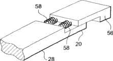
图9和图10为在远端使用推力弹簧的可操纵结构的透视图;9 and 10 are perspective views of a steerable structure using a push spring at the distal end;
图11为可变刚性的可操纵结构的轴向剖面示意图,所示可操纵结构的远端带有推力弹簧;Fig. 11 is a schematic axial cross-sectional view of a steerable structure with variable rigidity, the distal end of the steerable structure shown has a thrust spring;
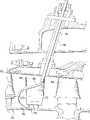
图12为涡轮机的部分轴向剖面示意图,所示为在本发明的可操纵结构帮助下进行的检查。Figure 12 is a partial axial cross-sectional view of a turbomachine shown inspected with the aid of the steerable structure of the present invention.
具体实施方式Detailed ways
首先参照图1,该图给出了根据现有技术的导管或内窥镜式可操纵结构10的示意图,其包括一个沿纵向轴线14的管状挠性体12,并包括了可收缩材料—例如形状记忆合金(SMA)型—的执行机构16,沿管状机构及其内部布置。所述执行机构采用金属线形式,与电源装置(图中未示)相连接。可操纵结构10带有一个静止近端18和一个可操纵的远端20。Referring first to FIG. 1 , there is shown a schematic diagram of a catheter or endoscopic
通过焦耳效应对形状记忆合金(SMA)材料进行加热,可以使得构成金属丝的原子重新排列(当达到活化温度时),引起收缩(响应时间不到一秒),从而使其长度缩短。固定到管状结构12壁上的金属丝16使得管子远端20沿与轴线14相垂直的方向弯曲(图2)。只要管子12的整个刚性实际是恒定的,这样弯曲而成的结构10则会呈现一种圆弧形外形,其弯曲半径实际上也是恒定的。如果必须限制导管的两个端部18和20之间的相对侧向移动,那么这种导管的远端20就需要能够按一定角度操纵转向,离开纵轴14仅仅几度。角度方向的较大变化将会导致导管远端20侧向移动。因此,这样的结构只能在带有狭窄通道且要求微调角度的系统内使用,不然的话,系统内的通道尺寸需要足够大,以允许进行较大程度的侧向位移,因此,使用范围受到严重限制,无法对非常复杂和狭窄区域的系统内部进行检查,例如,航空动力结构。Heating the shape-memory alloy (SMA) material through the Joule effect can cause the atoms that make up the wire to rearrange (when the activation temperature is reached), causing a contraction (response time of less than a second) that shortens its length. A
停止对金属丝进行焦耳效应加热会引起金属丝16冷却,进而引起可操纵结构10在弹性作用下回到初始纵向状态。Cessation of Joule-effect heating of the wire causes the
在本发明中,如图2所示,可操纵结构21由一个挠性本体22组成,其至少一部分具有可变刚性,SMA金属丝16在这个区域延伸。这种刚性变化可以在管子22的外表面上通过安装或形成特厚材料来实现。在所示示例中,第一特厚材料24位于管子22的周围,而后,第二特厚26材料位于第一特厚材料24的周围,第二特厚材料要比第一特厚材料轴向尺寸短。这样,挠性本体所提供的刚性就会从其近端18向其远端20逐渐减小。In the present invention, as shown in FIG. 2, the
通过焦耳效应加热使得金属丝16收缩期间,管子弯曲大约一个弯曲半径,这是可以变化的(图4)。管子在其具有较大刚性的部分弯曲程度很小,但在刚性较低的区域则弯曲程度较大。另外,还可以看到,其侧向移动较小,为此,与已有技术相比,远端20的给定角度操纵所需的空间也小。During the contraction of the
这样,就可以使得远端的操纵变化相对于纵轴14达到90°,而侧向位移量很小。只要管子22的直径相对于SMA金属丝16的尺寸并不是很大时,这种变化是可以实现的。In this way, maneuvering changes of the distal end up to 90° relative to the
一般情况下,金属丝16的直径约为0.5mm到0.1mm,经过焦耳效应加热而造成收缩(由大约0.5W的电力所产生),而所述收缩率是其长度的大约5%到6%。管子22的直径大约2mm到6mm,采用聚合物材料制成,例如目前的医用导管。于是,调整执行机构内传输的电流幅度可以用来调整收缩量,并从而调整了本体22的弯曲度。In general, the diameter of the
检查机器的内窥镜或导管所穿行的通道通常为狭窄槽的形式,特别是在具有轴向对称的系统内,诸如涡轮机。因此,导管无需采用管状,它可以是其它某种形状。所以,本发明同样可以适用于纵向挠性本体28,其具有细长横截面,如图5所示,此处本体28呈实际长方形截面的叶片形式。The channel through which the endoscope or catheter of the inspection machine travels is usually in the form of a narrow slot, especially in systems with axial symmetry, such as turbines. Thus, the catheter need not be tubular, it could be some other shape. Therefore, the invention is equally applicable to a longitudinally
按类似于上述实施例的方式,导管27包括一个挠性本体28,采用多层材料制成,形成特厚材料,从而可以沿纵向修正叶片刚性。增加的材料层是由同样为长方形截面的条带形成。在这个示例中,所述可操纵结构带有四层材料,或增加的条带,其宽度类似叶片28的宽度。第一条带30位于本体的一个表面上,而另一个条带32的长度与第一个一样,则位于其相反一面,在纵向本体28的另一端。具有相同长度的另外两个条带34,36分别位于两个第一条带30和32的其中一个上,但其长度则比第一条带30和32要短。In a manner similar to the above-described embodiment, the
两个SMA或收缩平行金属丝38安装在叶片28内,并与其纵向表面平行在其中平面上延伸。Two SMA or shrink
通过采用焦耳效应对金属丝38进行加热,就可以获得弯曲结构,即S形状(图6),因为从纵向体的近端18向远端20,刚性逐渐减小,然而,在叶片28的一个表面上弯曲度是恒定的,但在另一面上,则是逆向变化。当需要垂直于纵向轴线而对远端20补偿时,但同时又不会改变其角度方向,或者更普遍的是,当必须不仅要改变纵向体的弯曲度,而且要在某些特点区域使其变得相反时,这种结构特别有用。By using the Joule effect to heat the
图7所示可操纵结构为圆盘形。这种形状可以通过在挠性本体28的每一端加装特厚条带40来实现,这两个条带位于同一表面,而其背面带有沿本体28对准并位于端条带40之间的两个条带42。为了通过抵住周围静止构件44而稳定内窥镜或导管,可以使用这种类型的结构,从而可以限制重力对可操纵结构整体上的作用,这样就可以使用较长的更精良的导管,如果其只采用自支撑结构组成时,在如下所述的非破坏检查作业期间,悬挂或支撑装置同样也非常有用,因为非破坏检查要求导管远端20处在一个相对稳定的位置。The steerable structure shown in Figure 7 is disc-shaped. This shape can be achieved by attaching extra
使用三层不同长度的材料46,48和50,在叶片28的一个表面上相互堆叠而成,从而可以获得图8所示钩形结构。这样,纵向本体28的近端18就只少许弯曲,而大部分弯曲则集中在其远端20处,从而使得远端20能够移动一个角度,该角度大于90°,与此同时仍保持很小的侧向移动。Using three layers of
如图9和图10所示,导管或内窥镜可以包括弹性装置,该装置对装有非破坏检查装置的顶端施加一个纵向推力。这些弹性装置可以—例如—由螺旋状弹簧构成。As shown in Figures 9 and 10, the catheter or endoscope may include resilient means which apply a longitudinal thrust to the tip on which the non-destructive inspection device is mounted. These elastic means can, for example, consist of helical springs.
如果内窥镜或导管为管状时(图9),螺旋状弹簧52就位于挠性本体22的远端部分20周围并抵在纵向本体22的边缘上,而弹簧52的另一端则抵在位于弹簧52周围的帽子形构件54的端部。If the endoscope or catheter is tubular ( FIG. 9 ), the
如果挠性本体28(图10)为延长横截面,例如长方形横截面时,其远端20可以包括一个长方形阶梯,互补形状的顶端56在该阶梯上被导向移动。顶端56通过平行布置的两根弹簧58连接到纵向本体28上。If the flexible body 28 (FIG. 10) is of elongated cross-section, such as a rectangular cross-section, its
当导管靠近感兴趣的部件的表面时,在使用非破坏检查装置对所述部件检查所要求的时间内,弹簧52,58会使顶端54,56保持与所述表面接触。When the catheter is near the surface of the part of interest, the
当需要检查弹簧刚性或所施加力时,弹簧52,58可以用形状记忆或可收缩材料制成。这种弹簧也可用于精确控制顶端端部和表面之间的距离。The
图11示出了本发明的导管或内窥镜的两个位置,其中一个位置(A)对应于弹性变形前的初始状态,而另一个位置(B)对应于弹性变形后的状态。所述导管为带有细长横截面类型的导管,其包括两层材料60,62,布置在挠性体28的端部相对表面上,和两个SMA金属丝38,如图5所示,以及一个或多个将顶端56连接到挠性本体28上的弹簧58,所述顶端56与所感兴趣的部件64的表面相接触。Figure 11 shows two positions of the catheter or endoscope of the present invention, one position (A) corresponding to the initial state before elastic deformation and the other position (B) corresponding to the state after elastic deformation. The conduit is of the type with an elongated cross-section comprising two layers of
在焦耳效应加热期间,导管根据上述工作原理形成S形状,从而使得远端垂直于纵轴移动,而不改变方向。弹簧58的功能就是使顶端与部件64的表面始终保持接触。During Joule-effect heating, the catheter forms an S-shape according to the working principle described above, allowing the distal end to move perpendicular to the longitudinal axis without changing direction. The function of the
通过本装置和通过将非破坏检查装置置放在顶端56内,就可以通过扫描检查部件64的内部,而顶端56会因为SMA金属丝38的重复动作而直线移动。With this arrangement and by placing a non-destructive inspection device within the
非破坏性检查装置,诸如傅科电流探头或超声探头,都在探测表面裂痕方面特别有用。Non-destructive inspection devices, such as Foucault current probes or ultrasonic probes, are particularly useful in detecting surface flaws.
图12示出了涡轮机的一个级,包括改变由外壳体70围绕的动叶66和静叶68。静叶68的径向内端与安装在转子74部分上的档风板72相对准。这些档风板72用来防止静叶68和转子74之间出现任何空气流动。因此,重要的是检查这些部件的磨损状况,以避免涡轮机性能下降。FIG. 12 shows one stage of the turbine including changes to the
用于此项目的的导管或内窥镜是属于伸缩型的,即由多个装有可收缩执行机构并相互衔接的弹性可变形本体组成。The catheter or endoscope used in this project is telescopic, that is, it is composed of multiple elastically deformable bodies equipped with retractable actuators and connected to each other.
本发明的导管可以用来迅速而方便地检查这些档风板72。为此,第一管状刚性本体76插入内窥孔口78内,该孔口78向向两个相邻静叶68之间打开,而S形的第二挠性本体80则插入到第一本体内。执行机构加热装置可以使得导管80在两个静叶68之间的空间内成形。最后,只拥有一个弯曲方向的第三挠性本体82插入前两个导管78和80内,并被操纵控制,于是其顶端与档风板72相接触。涡轮机的转子而后转动,使得非破坏检查装置被置放到导管82的顶端内,对所述部分的表面状态进行360°的检查。顶端可以连接到上述的一根弹簧上,以确保持续接触。The catheter of the present invention can be used to quickly and easily inspect these
导管的总长度是相当长的,例如大约60cm,这会引起其远端定位误差。在诸如夹头或可展开式网格构件的协助下,静叶68可以用作中间导管80的支撑和悬挂点,以稳定整个可伸缩导管。The overall length of the catheter is quite long, for example about 60 cm, which can cause positioning errors at its distal end. The
可变刚度构型有助于导管移动到难以进入的区域,这些区域要求导管沿尺寸很小的通道穿行。The variable stiffness configuration facilitates movement of the catheter into hard-to-access areas that require the catheter to traverse small pathways.
如附图所示,细长横截面导管可以是实心的,但也可以是空心的。采用实心可伸缩导管时,可以提供导向装置,诸如沿纵向本体布置的轨道。As shown in the figures, the elongate cross-section conduit may be solid, but may also be hollow. Where a solid telescoping catheter is used, guide means, such as rails arranged along the longitudinal body, may be provided.
所述各种实施例中,可以使用不同数量的形状记忆合金(SMA)或可收缩金属丝和不同数量的特厚层材料,以便获得所要求的弯曲度轮廓。In the various embodiments described, different amounts of shape memory alloy (SMA) or shrinkable wire and different amounts of extra thick layer material may be used in order to obtain the desired curvature profile.
本发明并不仅限于附图所示实施例中使用的SMA形执行机构,即只在一个方向上动作的单作用SMA金属丝。另外,也可以使用其它执行机构,诸如SMA叶片,选择可记忆两个位置的执行机构,以便使得可操纵结构更快地回到初始状态。还有,也可进行这样的设想,即沿弹性体和在相反位置布置SMA金属丝,而后,再连续操纵金属丝动作,从而可更快地返回到初始状态。The invention is not limited to the SMA type actuators used in the embodiments shown in the drawings, ie, single acting SMA wires which act in only one direction. In addition, other actuators, such as SMA blades, can also be used, choosing an actuator that can memorize two positions, so that the steerable structure can return to the initial state more quickly. Also, it is conceivable to arrange the SMA wire along the elastic body and in the opposite position, and then to operate the wire continuously so as to return to the initial state more quickly.
尽管如上所述本发明特别适用于对复杂工业装置的三维检查领域,但也可用于其它领域,而且特别是生物医学领域,在这个领域,导管的可操纵性是成功实施解剖和功能检查分析的关键特性。Although the invention, as described above, is particularly applicable in the field of three-dimensional inspection of complex industrial installations, it can also be used in other fields, and especially in the biomedical field, where the maneuverability of catheters is the key to successfully performing anatomical and functional inspection analyses. key features.
本发明还涉及到包括自动控制装置的导管或内窥镜,所述装置连接到其每个可收缩执行机构上。这对用于确切已知几何结构的系统是特别有利的。通过使用这些系统,可以精确确定要穿行的路径,可操纵结构需要采用的形状,并从可操纵结构插入到内窥孔口开始就对其执行机构进行程序控制。The invention also relates to a catheter or endoscope comprising automatic control means connected to each of its retractable actuators. This is particularly advantageous for systems with exactly known geometries. Using these systems, it is possible to precisely determine the path to be traversed, the shape the steerable structure needs to adopt, and program its actuators from the time the steerable structure is inserted into the endoscopic orifice.
因为本发明实施方法简单,成本低,因而可以制造成专门用于某种类型系统的检查导管,并可以只对一种类型的部件进行非破坏检查。Because the implementation method of the present invention is simple and the cost is low, it can be manufactured as an inspection catheter specially used for a certain type of system, and non-destructive inspection can be performed on only one type of components.
为此,根据其要实施的区域和非破坏检查的类型,对本发明的可操纵结构的制造进行优化,从而为用户提供重大性能改进后的装置。To this end, the manufacture of the steerable structure of the present invention is optimized according to the area and the type of non-destructive inspection it is to perform, thereby providing the user with a device with significantly improved performance.
可收缩材料可以是,例如,镍钛合金。挠性本体和各层材料可以是弹簧钢或聚合物制成,诸如聚酮乙基醚、环氧树脂、聚乙烯、或聚亚安酯,这取决于所要求的刚性。The shrinkable material can be, for example, Nitinol. The flexible body and layers can be made of spring steel or polymers such as polyketone, epoxy, polyethylene, or polyurethane, depending on the rigidity required.
本发明并不仅限于长方形或圆形截面的导管,它同样适用于任意横截面的导管,例如椭圆形、方形、三角形等。The invention is not limited to ducts of rectangular or circular cross-section, but is equally applicable to ducts of any cross-section, such as oval, square, triangular, etc.
Claims (20)
Applications Claiming Priority (2)
| Application Number | Priority Date | Filing Date | Title |
|---|---|---|---|
| FR07/06726 | 2007-09-26 | ||
| FR0706726AFR2921499B1 (en) | 2007-09-26 | 2007-09-26 | CATHETER OR ENDOSCOPE-TYPE ORIENTABLE STRUCTURE |
Publications (2)
| Publication Number | Publication Date |
|---|---|
| CN101416868A CN101416868A (en) | 2009-04-29 |
| CN101416868Btrue CN101416868B (en) | 2012-07-18 |
Family
ID=39325897
Family Applications (1)
| Application Number | Title | Priority Date | Filing Date |
|---|---|---|---|
| CN2008101671455AActiveCN101416868B (en) | 2007-09-26 | 2008-09-26 | Guidable structure such as a catheter or an endoscope |
Country Status (7)
| Country | Link |
|---|---|
| US (1) | US8558878B2 (en) |
| EP (1) | EP2042076B1 (en) |
| JP (1) | JP5618471B2 (en) |
| CN (1) | CN101416868B (en) |
| CA (1) | CA2639985C (en) |
| FR (1) | FR2921499B1 (en) |
| RU (1) | RU2503049C2 (en) |
Families Citing this family (41)
| Publication number | Priority date | Publication date | Assignee | Title |
|---|---|---|---|---|
| US7502068B2 (en)* | 2004-06-22 | 2009-03-10 | International Business Machines Corporation | Sensor for imaging inside equipment |
| FR2946723B1 (en)* | 2009-06-10 | 2011-08-05 | Snecma | NON-DESTRUCTIVE CONTROL OF A SEALING LECHET |
| FR2947910B1 (en)* | 2009-07-09 | 2011-07-29 | Snecma | METHOD FOR THE DEVELOPMENT AND CALIBRATION OF A NON-DESTRUCTIVE CONTROL TOOL OF PIECES OF A TURBOMACHINE |
| FR2947909B1 (en)* | 2009-07-09 | 2011-12-23 | Snecma | DEVICE FOR NON-DESTRUCTIVE CONTROL OF PARTS IN A TURBOMACHINE |
| FR2947911B1 (en)* | 2009-07-09 | 2011-06-17 | Snecma | DEVICE FOR CONTROLLING A TURBOMACHINE ENGINE |
| GB2474253A (en) | 2009-10-08 | 2011-04-13 | Surgical Innovations Ltd | Flexible endoscope controllable between extended and crossed configurations |
| FR2955177B1 (en) | 2010-01-14 | 2012-07-27 | Snecma | GUIDED STRUCTURE OF THE ENDOSCOPE TYPE |
| JP5572417B2 (en)* | 2010-02-17 | 2014-08-13 | オリンパス株式会社 | Guide device |
| GB201003516D0 (en) | 2010-03-03 | 2010-04-21 | Surgical Innovations Ltd | Instruments |
| CN102985023B (en)* | 2010-06-30 | 2015-11-25 | 皇家飞利浦电子股份有限公司 | For applying the energy application devices of energy to object |
| AU2011316783A1 (en)* | 2010-10-22 | 2013-05-23 | W. L. Gore & Associates, Inc. | Catheter with shape memory alloy actuator |
| EP2799861B1 (en) | 2013-04-30 | 2018-01-10 | General Electric Technology GmbH | Ultrasonic component inspection apparatus and method with a conformable guide member |
| KR102088849B1 (en)* | 2013-05-30 | 2020-03-13 | 삼성메디슨 주식회사 | Ultrasound Probe and Manufacturing Method thereof |
| FR3008184B1 (en)* | 2013-07-03 | 2017-01-27 | Eurocopter France | SYSTEM AND METHOD FOR MONITORING A ROTATIONAL MONITOR THAT IS AGENCED IN A MECHANICAL MEMBER |
| JP2016021996A (en)* | 2014-07-16 | 2016-02-08 | 株式会社日本自動車部品総合研究所 | Stuffed animal robot |
| US10542877B2 (en) | 2014-08-29 | 2020-01-28 | Endochoice, Inc. | Systems and methods for varying stiffness of an endoscopic insertion tube |
| US9625286B2 (en)* | 2015-01-09 | 2017-04-18 | Olympus Scientific Solutions Americas Inc. | Adjustable probe holder assembly for an inspection sensor |
| KR102555373B1 (en)* | 2016-03-28 | 2023-07-13 | 엘지전자 주식회사 | Detection device for turbomachine system |
| US11000265B1 (en)* | 2016-06-20 | 2021-05-11 | Intelligent Fiber Optic Systems, Inc. | Steerable biopsy needle with fiber-activated shape memory alloy |
| CN109414568A (en)* | 2016-06-29 | 2019-03-01 | 皇家飞利浦有限公司 | Deflectable equipment with elongate actuator |
| JP6602979B2 (en)* | 2016-07-11 | 2019-11-06 | オリンパス株式会社 | Endoscope device |
| WO2018083762A1 (en)* | 2016-11-02 | 2018-05-11 | オリンパス株式会社 | Variable stiffness actuator |
| KR101871221B1 (en)* | 2017-02-17 | 2018-06-27 | 재단법인 아산사회복지재단 | Multi-culvature cathether and medical device for surgery |
| WO2018170095A1 (en)* | 2017-03-14 | 2018-09-20 | President And Fellows Of Harvard College | Systems and methods for providing stabilization for endoscopic procedures |
| CN107361727B (en)* | 2017-07-17 | 2019-06-04 | 天津大学 | A rigidity controllable instrument for natural orifice surgery and application method thereof |
| RU2661096C1 (en)* | 2018-04-16 | 2018-07-11 | Государственное бюджетное учреждение здравоохранения города Москвы Научно-исследовательский институт скорой помощи имени Н.В. Склифосовского Департамента здравоохранения г. Москвы | Method of selecting the catheter size for catheterization of bronchial and intercostal branches of the thoracic aorta |
| RU2661417C1 (en)* | 2018-04-16 | 2018-07-16 | Государственное бюджетное учреждение здравоохранения города Москвы Научно-исследовательский институт скорой помощи имени Н.В. Склифосовского Департамента здравоохранения г. Москвы | Angiographic bronchial catheter for catheterization of bronchial and intercostal arteries |
| RU2681756C1 (en)* | 2018-07-11 | 2019-03-12 | Государственное бюджетное учреждение здравоохранения города Москвы Научно-исследовательский институт скорой помощи имени Н.В. Склифосовского Департамента здравоохранения г. Москвы | Catheter for selective bronchial arteriography with a transvenous access through a defect in the interventricular septum |
| WO2020084133A1 (en)* | 2018-10-25 | 2020-04-30 | Basecamp Vascular | Steerable elongated functional system |
| DE102019101089A1 (en) | 2019-01-16 | 2020-07-16 | Vizaar Industrial Imaging Ag | Endoscopic probe actuator, endoscopic probe, and method for controlling an endoscopic probe actuator |
| JP7216183B2 (en)* | 2019-03-07 | 2023-01-31 | 富士フイルム株式会社 | Endoscope |
| FR3094397B1 (en)* | 2019-03-25 | 2021-05-14 | Safran Aircraft Engines | DEVICE AND METHOD FOR NON-DESTRUCTIVE CONTROL OF A ROTOR OF A CONTRAROTARY TURBINE OF AN AIRCRAFT TURBOMACHINE |
| CN112107104A (en)* | 2019-06-19 | 2020-12-22 | 阿蓓亚塑料实业(上海)有限公司 | Container for rod-shaped material |
| CN111396274B (en)* | 2020-04-03 | 2022-05-13 | 中国科学技术大学 | A sensor-driven integrated thin-plate driver based on shape memory alloy |
| CN111650741A (en)* | 2020-06-23 | 2020-09-11 | 中核武汉核电运行技术股份有限公司 | endoscope guidance system |
| CN112068303B (en)* | 2020-08-04 | 2022-05-27 | 国网湖南省电力有限公司 | An endoscope device for cable trench detection |
| US11977217B2 (en)* | 2020-12-04 | 2024-05-07 | General Electric Company | Insertion tool |
| CN113063674B (en)* | 2021-03-23 | 2022-06-17 | 重庆大学 | Method and device for observing bending failure process of metal material by gradient curvature method |
| CN114938937B (en)* | 2022-05-18 | 2024-03-08 | 湖南省华芯医疗器械有限公司 | Haulage rope pretension structure, endoscope handle and endoscope |
| US20250284113A1 (en)* | 2024-03-07 | 2025-09-11 | Rtx Corporation | Use of memorized alloy for inaccessible location |
| CN117860177B (en)* | 2024-03-08 | 2024-05-31 | 深圳科思明德医疗科技有限公司 | Elbow assembly and endoscope |
Citations (3)
| Publication number | Priority date | Publication date | Assignee | Title |
|---|---|---|---|---|
| EP0199870A2 (en)* | 1985-05-03 | 1986-11-05 | Catheter Research, Inc. | Steerable and aimable catheter |
| EP0279316A2 (en)* | 1987-02-09 | 1988-08-24 | Sumitomo Electric Industries Limited | Mechanism for bending elongated body |
| US6960162B2 (en)* | 2002-06-13 | 2005-11-01 | Usgi Medical Inc. | Shape lockable apparatus and method for advancing an instrument through unsupported anatomy |
Family Cites Families (39)
| Publication number | Priority date | Publication date | Assignee | Title |
|---|---|---|---|---|
| JPS58108801U (en)* | 1982-01-14 | 1983-07-25 | 旭光学工業株式会社 | Endoscope |
| JPS6264330A (en)* | 1985-09-17 | 1987-03-23 | オリンパス光学工業株式会社 | Endoscope |
| US4790624A (en)* | 1986-10-31 | 1988-12-13 | Identechs Corporation | Method and apparatus for spatially orienting movable members using shape memory effect alloy actuator |
| JPS63194630A (en)* | 1987-02-09 | 1988-08-11 | 住友電気工業株式会社 | Bending mechanism of long body |
| US5079943A (en)* | 1988-02-05 | 1992-01-14 | Cte Chem Tec Equipment Co. Inc. | Method of calibrating a volumetric fluid flow sensor |
| US5531664A (en)* | 1990-12-26 | 1996-07-02 | Olympus Optical Co., Ltd. | Bending actuator having a coil sheath with a fixed distal end and a free proximal end |
| JPH05272446A (en)* | 1992-01-30 | 1993-10-19 | Terumo Corp | Bending-stretching mechanism type actuator |
| US5279559A (en)* | 1992-03-06 | 1994-01-18 | Aai Corporation | Remote steering system for medical catheter |
| US5624380A (en)* | 1992-03-12 | 1997-04-29 | Olympus Optical Co., Ltd. | Multi-degree of freedom manipulator |
| FR2697995B1 (en)* | 1992-11-19 | 1994-12-30 | Celsa Lg | Removable blood filtration device, with variable rigidity, implantable in the body of a patient and allowing the injection of a treating product. |
| JPH06154156A (en)* | 1992-11-24 | 1994-06-03 | Toshiba Corp | Scope for endoscope device |
| US5487757A (en)* | 1993-07-20 | 1996-01-30 | Medtronic Cardiorhythm | Multicurve deflectable catheter |
| JPH07259725A (en)* | 1994-03-17 | 1995-10-09 | Olympus Optical Co Ltd | Flexible tube curing device |
| JPH08141971A (en)* | 1994-11-21 | 1996-06-04 | Olympus Optical Co Ltd | Manipulator |
| FR2730787B1 (en)* | 1995-02-21 | 1997-04-04 | Cga Hbs | PROBE FOR TUBES |
| US5827272A (en)* | 1995-08-07 | 1998-10-27 | Medtronic Cardiorhythm | Simplified torquing electrode catheter |
| US5810717A (en)* | 1995-09-22 | 1998-09-22 | Mitsubishi Cable Industries, Ltd. | Bending mechanism and stereoscope using same |
| JP3845147B2 (en)* | 1996-07-25 | 2006-11-15 | オリンパス株式会社 | Flexible tube |
| US5846247A (en)* | 1996-11-15 | 1998-12-08 | Unsworth; John D. | Shape memory tubular deployment system |
| RU2134405C1 (en)* | 1997-02-10 | 1999-08-10 | Казанский государственный технический университет им.А.Н.Туполева | Flowmeter - gasmeter |
| JPH1152256A (en)* | 1997-08-07 | 1999-02-26 | Olympus Optical Co Ltd | Image pickup head for observation |
| JP2003521261A (en)* | 1997-12-22 | 2003-07-15 | マイクルス コーポレイション | Variable rigidity optical fiber shaft |
| US6245053B1 (en)* | 1998-11-09 | 2001-06-12 | Medtronic, Inc. | Soft tip guiding catheter and method of fabrication |
| JP2000161543A (en)* | 1998-12-01 | 2000-06-16 | Terumo Corp | Flexible pipe |
| JP4096325B2 (en)* | 1998-12-14 | 2008-06-04 | 正喜 江刺 | Active capillary and method for manufacturing the same |
| US6203494B1 (en)* | 1999-03-02 | 2001-03-20 | Olympus Optical Co., Ltd. | Endoscope capable of varying hardness of flexible part of insertion unit thereof |
| US6574958B1 (en)* | 1999-08-12 | 2003-06-10 | Nanomuscle, Inc. | Shape memory alloy actuators and control methods |
| US6425418B1 (en)* | 1999-10-27 | 2002-07-30 | Mitsubishi Cable Industries, Ltd. | Flexible tube and manufacturing method for the same |
| US6860849B2 (en)* | 2000-05-08 | 2005-03-01 | Pentax Corporation | Flexible tube for an endoscope |
| JP3579646B2 (en)* | 2000-11-21 | 2004-10-20 | ペンタックス株式会社 | Ultrasound endoscope |
| JP2002207178A (en)* | 2001-01-04 | 2002-07-26 | Olympus Optical Co Ltd | Endoscope |
| US6872433B2 (en)* | 2001-03-27 | 2005-03-29 | The Regents Of The University Of California | Shape memory alloy/shape memory polymer tools |
| US7780693B2 (en)* | 2001-06-27 | 2010-08-24 | Salviac Limited | Catheter |
| US6898984B2 (en)* | 2002-08-16 | 2005-05-31 | Levitronix Llc | Measuring apparatus to determine the flow of a fluid |
| JP4009519B2 (en)* | 2002-10-25 | 2007-11-14 | オリンパス株式会社 | Endoscope |
| ITTO20030218A1 (en)* | 2003-03-25 | 2004-09-26 | Fiat Ricerche | PROBE, IN PARTICULAR FOR TUBULAR CAVITIES. |
| JP4418202B2 (en)* | 2003-10-06 | 2010-02-17 | オリンパス株式会社 | Endoscope |
| US7744604B2 (en)* | 2003-11-13 | 2010-06-29 | Lawrence Livermore National Security, Llc | Shape memory polymer medical device |
| WO2005115117A2 (en)* | 2004-05-24 | 2005-12-08 | The Trustees Of Columbia University In The City Of New York | Steerable devices |
- 2007
- 2007-09-26FRFR0706726Apatent/FR2921499B1/enactiveActive
- 2008
- 2008-09-09EPEP08163918.9Apatent/EP2042076B1/enactiveActive
- 2008-09-22USUS12/235,148patent/US8558878B2/enactiveActive
- 2008-09-24JPJP2008243726Apatent/JP5618471B2/enactiveActive
- 2008-09-25CACA2639985Apatent/CA2639985C/enactiveActive
- 2008-09-25RURU2008138272/28Apatent/RU2503049C2/enactive
- 2008-09-26CNCN2008101671455Apatent/CN101416868B/enactiveActive
Patent Citations (3)
| Publication number | Priority date | Publication date | Assignee | Title |
|---|---|---|---|---|
| EP0199870A2 (en)* | 1985-05-03 | 1986-11-05 | Catheter Research, Inc. | Steerable and aimable catheter |
| EP0279316A2 (en)* | 1987-02-09 | 1988-08-24 | Sumitomo Electric Industries Limited | Mechanism for bending elongated body |
| US6960162B2 (en)* | 2002-06-13 | 2005-11-01 | Usgi Medical Inc. | Shape lockable apparatus and method for advancing an instrument through unsupported anatomy |
Also Published As
| Publication number | Publication date |
|---|---|
| US8558878B2 (en) | 2013-10-15 |
| CA2639985C (en) | 2016-03-15 |
| FR2921499A1 (en) | 2009-03-27 |
| JP2009104121A (en) | 2009-05-14 |
| US20090079821A1 (en) | 2009-03-26 |
| EP2042076A3 (en) | 2010-05-26 |
| RU2008138272A (en) | 2010-03-27 |
| JP5618471B2 (en) | 2014-11-05 |
| RU2503049C2 (en) | 2013-12-27 |
| EP2042076B1 (en) | 2015-09-09 |
| CN101416868A (en) | 2009-04-29 |
| CA2639985A1 (en) | 2009-03-26 |
| EP2042076A2 (en) | 2009-04-01 |
| FR2921499B1 (en) | 2009-11-13 |
Similar Documents
| Publication | Publication Date | Title |
|---|---|---|
| CN101416868B (en) | Guidable structure such as a catheter or an endoscope | |
| US20190083749A1 (en) | Surgical device tip with arc length varying curvature | |
| US12405187B2 (en) | Insertion apparatus for use with rotary machines | |
| US5152748A (en) | Medical catheters thermally manipulated by fiber optic bundles | |
| JP5107065B2 (en) | Inner diameter measuring tool | |
| JP4962750B2 (en) | In particular a bending deformation device for endoscopy and / or minimally invasive surgical instruments | |
| JP6785783B2 (en) | Connecting neck and neck forming method for ultrasonic probe | |
| CN101322865A (en) | Bendable stylet | |
| US9625286B2 (en) | Adjustable probe holder assembly for an inspection sensor | |
| JP2013517522A (en) | Endoscopic steerable structure | |
| FR2981260A1 (en) | DEVICE FOR GUIDING A MEDICAL NEEDLE | |
| JPH0546214B2 (en) | ||
| CN110869060A (en) | Instrument box for operating instrument | |
| JP7634208B2 (en) | Method and device for controlling a non-destructive testing device - Patents.com | |
| CN113924048A (en) | Systems and methods for organ retraction and space opening | |
| CN212515210U (en) | Endoscope guiding system | |
| JP6599677B2 (en) | Endoscope device | |
| US12402913B2 (en) | Steerable surgical devices, and methods for their use and tracking | |
| JPH01255822A (en) | Endoscope | |
| CN112610291A (en) | Insertion device for use with a rotary machine | |
| JP2002250272A (en) | Oscillating structure body | |
| KR101958218B1 (en) | The apparatus of measuring size of the target inside body cavity | |
| Ryu | Optically Controlled Magnetic Resonance Imaging Compatible Active Needle | |
| WO2021183389A1 (en) | Endoscopic snare device | |
| JP2011087882A (en) | Control system for multilayer conduit |
Legal Events
| Date | Code | Title | Description |
|---|---|---|---|
| C06 | Publication | ||
| PB01 | Publication | ||
| C10 | Entry into substantive examination | ||
| SE01 | Entry into force of request for substantive examination | ||
| C14 | Grant of patent or utility model | ||
| GR01 | Patent grant |