CN101410689B - Systems and methods for electronic weaponry with deployment unit detection - Google Patents
Systems and methods for electronic weaponry with deployment unit detectionDownload PDFInfo
- Publication number
- CN101410689B CN101410689BCN2006800316953ACN200680031695ACN101410689BCN 101410689 BCN101410689 BCN 101410689BCN 2006800316953 ACN2006800316953 ACN 2006800316953ACN 200680031695 ACN200680031695 ACN 200680031695ACN 101410689 BCN101410689 BCN 101410689B
- Authority
- CN
- China
- Prior art keywords
- emitter
- deployment unit
- mark
- function
- target
- Prior art date
- Legal status (The legal status is an assumption and is not a legal conclusion. Google has not performed a legal analysis and makes no representation as to the accuracy of the status listed.)
- Expired - Fee Related
Links
- 238000000034methodMethods0.000titleclaimsabstractdescription61
- 238000001514detection methodMethods0.000titleclaimsabstractdescription20
- 238000004891communicationMethods0.000claimsdescription52
- 238000003860storageMethods0.000claimsdescription27
- 230000004044responseEffects0.000claimsdescription25
- 230000004913activationEffects0.000claimsdescription3
- 208000002173dizzinessDiseases0.000claims4
- 230000006870functionEffects0.000abstractdescription228
- 238000012545processingMethods0.000abstractdescription77
- 239000003550markerSubstances0.000abstractdescription6
- 230000000638stimulationEffects0.000description90
- 230000015654memoryEffects0.000description41
- 238000010304firingMethods0.000description35
- 239000003990capacitorSubstances0.000description32
- 208000028659dischargeDiseases0.000description30
- 238000004804windingMethods0.000description25
- 210000002027skeletal muscleAnatomy0.000description24
- 238000007600chargingMethods0.000description22
- 210000001519tissueAnatomy0.000description17
- 230000033001locomotionEffects0.000description15
- 230000008602contractionEffects0.000description13
- 238000010586diagramMethods0.000description12
- 238000012546transferMethods0.000description10
- 230000008859changeEffects0.000description9
- 235000014676Phragmites communisNutrition0.000description8
- 238000005516engineering processMethods0.000description8
- 230000003287optical effectEffects0.000description8
- 230000007958sleepEffects0.000description8
- 230000008878couplingEffects0.000description7
- 238000010168coupling processMethods0.000description7
- 238000005859coupling reactionMethods0.000description7
- 230000015556catabolic processEffects0.000description6
- 239000007789gasSubstances0.000description6
- 230000008569processEffects0.000description5
- 230000005540biological transmissionEffects0.000description4
- 230000001413cellular effectEffects0.000description4
- 238000005286illuminationMethods0.000description4
- 230000000977initiatory effectEffects0.000description4
- 239000004065semiconductorSubstances0.000description4
- 230000008093supporting effectEffects0.000description4
- 241001465754MetazoaSpecies0.000description3
- 230000009471actionEffects0.000description3
- 238000004458analytical methodMethods0.000description3
- 238000006243chemical reactionMethods0.000description3
- 230000003247decreasing effectEffects0.000description3
- 238000004146energy storageMethods0.000description3
- 230000004907fluxEffects0.000description3
- 238000011990functional testingMethods0.000description3
- 230000001976improved effectEffects0.000description3
- 230000001965increasing effectEffects0.000description3
- 230000001939inductive effectEffects0.000description3
- 238000009434installationMethods0.000description3
- 230000004118muscle contractionEffects0.000description3
- 239000000725suspensionSubstances0.000description3
- 230000000007visual effectEffects0.000description3
- 230000003213activating effectEffects0.000description2
- 238000003491arrayMethods0.000description2
- 239000004020conductorSubstances0.000description2
- 238000011109contaminationMethods0.000description2
- 230000001276controlling effectEffects0.000description2
- 238000012423maintenanceMethods0.000description2
- 230000014759maintenance of locationEffects0.000description2
- 238000007726management methodMethods0.000description2
- 238000004519manufacturing processMethods0.000description2
- 239000000203mixtureSubstances0.000description2
- 239000004570mortar (masonry)Substances0.000description2
- 230000005855radiationEffects0.000description2
- 230000021670response to stimulusEffects0.000description2
- LFQSCWFLJHTTHZ-UHFFFAOYSA-NEthanolChemical compoundCCOLFQSCWFLJHTTHZ-UHFFFAOYSA-N0.000description1
- 206010034960PhotophobiaDiseases0.000description1
- 241000269400SirenidaeSpecies0.000description1
- 208000012886VertigoDiseases0.000description1
- 238000013459approachMethods0.000description1
- 230000006399behaviorEffects0.000description1
- 230000008901benefitEffects0.000description1
- 230000015572biosynthetic processEffects0.000description1
- 230000002301combined effectEffects0.000description1
- 238000007405data analysisMethods0.000description1
- 238000013480data collectionMethods0.000description1
- 230000009849deactivationEffects0.000description1
- 230000007123defenseEffects0.000description1
- 230000001066destructive effectEffects0.000description1
- 238000007599dischargingMethods0.000description1
- 239000000428dustSubstances0.000description1
- 230000000694effectsEffects0.000description1
- 238000010891electric arcMethods0.000description1
- 230000005684electric fieldEffects0.000description1
- 238000005265energy consumptionMethods0.000description1
- 230000007613environmental effectEffects0.000description1
- 230000005669field effectEffects0.000description1
- 238000009472formulationMethods0.000description1
- 230000007274generation of a signal involved in cell-cell signalingEffects0.000description1
- 230000036449good healthEffects0.000description1
- 239000003721gunpowderSubstances0.000description1
- 231100001261hazardousToxicity0.000description1
- 238000010438heat treatmentMethods0.000description1
- 208000013469light sensitivityDiseases0.000description1
- 239000007788liquidSubstances0.000description1
- 238000000691measurement methodMethods0.000description1
- 230000006386memory functionEffects0.000description1
- 230000003278mimic effectEffects0.000description1
- 230000004048modificationEffects0.000description1
- 238000012986modificationMethods0.000description1
- 239000004081narcotic agentSubstances0.000description1
- 239000013307optical fiberSubstances0.000description1
- 238000004806packaging method and processMethods0.000description1
- 239000000843powderSubstances0.000description1
- 238000002360preparation methodMethods0.000description1
- 230000001105regulatory effectEffects0.000description1
- 230000003252repetitive effectEffects0.000description1
- 238000011160researchMethods0.000description1
- 230000029058respiratory gaseous exchangeEffects0.000description1
- 230000002207retinal effectEffects0.000description1
- 238000012552reviewMethods0.000description1
- 238000010187selection methodMethods0.000description1
- 230000035939shockEffects0.000description1
- 230000008054signal transmissionEffects0.000description1
- 230000004936stimulating effectEffects0.000description1
- 239000013589supplementSubstances0.000description1
- 230000001360synchronised effectEffects0.000description1
- 230000008685targetingEffects0.000description1
- 230000003797telogen phaseEffects0.000description1
- 238000012360testing methodMethods0.000description1
- 238000013334tissue modelMethods0.000description1
- 238000012549trainingMethods0.000description1
- 230000007704transitionEffects0.000description1
- 231100000889vertigoToxicity0.000description1
Images


Classifications
- F—MECHANICAL ENGINEERING; LIGHTING; HEATING; WEAPONS; BLASTING
- F41—WEAPONS
- F41B—WEAPONS FOR PROJECTING MISSILES WITHOUT USE OF EXPLOSIVE OR COMBUSTIBLE PROPELLANT CHARGE; WEAPONS NOT OTHERWISE PROVIDED FOR
- F41B6/00—Electromagnetic launchers ; Plasma-actuated launchers
- F—MECHANICAL ENGINEERING; LIGHTING; HEATING; WEAPONS; BLASTING
- F41—WEAPONS
- F41H—ARMOUR; ARMOURED TURRETS; ARMOURED OR ARMED VEHICLES; MEANS OF ATTACK OR DEFENCE, e.g. CAMOUFLAGE, IN GENERAL
- F41H13/00—Means of attack or defence not otherwise provided for
- F41H13/0043—Directed energy weapons, i.e. devices that direct a beam of high energy content toward a target for incapacitating or destroying the target
- F41H13/0087—Directed energy weapons, i.e. devices that direct a beam of high energy content toward a target for incapacitating or destroying the target the high-energy beam being a bright light, e.g. for dazzling or blinding purposes
- F—MECHANICAL ENGINEERING; LIGHTING; HEATING; WEAPONS; BLASTING
- F41—WEAPONS
- F41A—FUNCTIONAL FEATURES OR DETAILS COMMON TO BOTH SMALLARMS AND ORDNANCE, e.g. CANNONS; MOUNTINGS FOR SMALLARMS OR ORDNANCE
- F41A17/00—Safety arrangements, e.g. safeties
- F41A17/06—Electric or electromechanical safeties
- F41A17/063—Electric or electromechanical safeties comprising a transponder
- F—MECHANICAL ENGINEERING; LIGHTING; HEATING; WEAPONS; BLASTING
- F41—WEAPONS
- F41A—FUNCTIONAL FEATURES OR DETAILS COMMON TO BOTH SMALLARMS AND ORDNANCE, e.g. CANNONS; MOUNTINGS FOR SMALLARMS OR ORDNANCE
- F41A17/00—Safety arrangements, e.g. safeties
- F41A17/06—Electric or electromechanical safeties
- F41A17/066—Electric or electromechanical safeties having means for recognizing biometric parameters, e.g. voice control, finger print or palm print control
- F—MECHANICAL ENGINEERING; LIGHTING; HEATING; WEAPONS; BLASTING
- F41—WEAPONS
- F41H—ARMOUR; ARMOURED TURRETS; ARMOURED OR ARMED VEHICLES; MEANS OF ATTACK OR DEFENCE, e.g. CAMOUFLAGE, IN GENERAL
- F41H13/00—Means of attack or defence not otherwise provided for
- F41H13/0012—Electrical discharge weapons, e.g. for stunning
- F41H13/0018—Electrical discharge weapons, e.g. for stunning for nearby electrical discharge, i.e. the electrodes being positioned on the device and the device brought manually or otherwise into contact with a nearby target
- F—MECHANICAL ENGINEERING; LIGHTING; HEATING; WEAPONS; BLASTING
- F41—WEAPONS
- F41H—ARMOUR; ARMOURED TURRETS; ARMOURED OR ARMED VEHICLES; MEANS OF ATTACK OR DEFENCE, e.g. CAMOUFLAGE, IN GENERAL
- F41H13/00—Means of attack or defence not otherwise provided for
- F41H13/0012—Electrical discharge weapons, e.g. for stunning
- F41H13/0025—Electrical discharge weapons, e.g. for stunning for remote electrical discharge via conducting wires, e.g. via wire-tethered electrodes shot at a target
- H—ELECTRICITY
- H05—ELECTRIC TECHNIQUES NOT OTHERWISE PROVIDED FOR
- H05C—ELECTRIC CIRCUITS OR APPARATUS SPECIALLY DESIGNED FOR USE IN EQUIPMENT FOR KILLING, STUNNING, OR GUIDING LIVING BEINGS
- H05C1/00—Circuits or apparatus for generating electric shock effects
- H05C1/04—Circuits or apparatus for generating electric shock effects providing pulse voltages
- H05C1/06—Circuits or apparatus for generating electric shock effects providing pulse voltages operating only when touched
Landscapes
- Engineering & Computer Science (AREA)
- General Engineering & Computer Science (AREA)
- Radar, Positioning & Navigation (AREA)
- Remote Sensing (AREA)
- Life Sciences & Earth Sciences (AREA)
- Insects & Arthropods (AREA)
- Physics & Mathematics (AREA)
- Electromagnetism (AREA)
- Plasma & Fusion (AREA)
- Electrotherapy Devices (AREA)
- User Interface Of Digital Computer (AREA)
- Electrostatic Spraying Apparatus (AREA)
- Air Bags (AREA)
- Aiming, Guidance, Guns With A Light Source, Armor, Camouflage, And Targets (AREA)
- Burglar Alarm Systems (AREA)
- Measurement Of The Respiration, Hearing Ability, Form, And Blood Characteristics Of Living Organisms (AREA)
- Geophysics And Detection Of Objects (AREA)
- Magnetic Resonance Imaging Apparatus (AREA)
- Nitrogen Condensed Heterocyclic Rings (AREA)
- Plural Heterocyclic Compounds (AREA)
- Investigating Or Analyzing Materials By The Use Of Electric Means (AREA)
- Arrangements For Transmission Of Measured Signals (AREA)
- Peptides Or Proteins (AREA)
- Heterocyclic Carbon Compounds Containing A Hetero Ring Having Oxygen Or Sulfur (AREA)
- Electrolytic Production Of Non-Metals, Compounds, Apparatuses Therefor (AREA)
Abstract
Translated fromChinese
Description
Translated fromChinese技术领域technical field
本发明涉及包括电子控制装置的武器。The invention relates to weapons comprising electronic control means.
背景技术Background technique
传统的电子武器包括,例如,接触眩晕(stun)装置、警棍、盾、眩晕枪、手枪、来复枪(RIFLE)、迫击炮、手榴弹、射弹、地雷以及区域保护装置以及其他设备,它们通常适合于确保服从安全性和法律的执行。当使用这种类型的武器对付人或动物目标时,会引起电流流过目标的组织的一部分,以妨碍目标使用其骨骼肌。所有或部分电子电路可以朝向目标推进(propel)。在电子武器的一种重要应用中,可以阻止恐怖分子的攻击并阻止其完成涉及武力获得对设施、设备、操作者、无辜平民以及执法人员的非法控制的行动。在其他电子武器重要应用中,执法官员可以逮捕嫌疑犯,且安全官员可维持被拘留人员与其协作。电子武器一般包括产生刺激信号(stimulus signal)的电路和一个或更多个电极。在操作中,例如,为了阻止恐怖分子的行动,将电极从电子武器朝向需阻止或控制的人推进。在发生冲击后,脉冲电流在电极之间传导,足以妨碍此人使用他的或她的骨骼肌。妨碍可以包括以每秒收缩5到20次的速率不能自己的、反复的、强烈的肌肉收缩。Traditional electronic weapons include, for example, contact stun (stun) devices, batons, shields, stun guns, pistols, rifles (RIFLE), mortars, grenades, projectiles, mines, and area protection devices and other equipment, which are often suitable for To ensure compliance with security and law enforcement. When this type of weapon is used against a human or animal target, it causes an electrical current to flow through a portion of the target's tissue, preventing the target from using its skeletal muscles. All or part of the electronic circuit can be propeled towards the target. In one important application of electronic weapons, terrorist attacks and operations involving the use of force to gain unlawful control over facilities, equipment, operators, innocent civilians, and law enforcement personnel can be prevented. Among other important applications of electronic weapons, law enforcement officials can apprehend suspects and security officials can maintain the cooperation of detained persons. Electronic weapons generally include circuitry to generate a stimulus signal and one or more electrodes. In operation, for example, to deter terrorists, electrodes are advanced from electronic weapons towards the person to be deterred or controlled. After a shock, a pulse of electrical current is conducted between the electrodes sufficient to prevent the person from using his or her skeletal muscles. Impediment can include inability to own, repetitive, intense muscle contractions at a rate of 5 to 20 contractions per second.
研究已经表明,肌肉收缩的强度和身体受肌肉收缩影响的程度取决于若干因素,包括身体由脉冲电流传导、充电或放电的程度。所述程度一般随电极之间距离的增加而变大。最小的合适距离典型地是约7英寸。在推进之前,这些电极通常被接近得多地被贮存在一起,而在朝目标飞行时散开。提高电极打击目标的准确度是人们期望的。Research has shown that the strength of the muscle contraction and the degree to which the body is affected by the muscle contraction depends on several factors, including the degree to which the body is conducted, charged or discharged by the impulse current. The extent generally increases with increasing distance between the electrodes. A minimum suitable distance is typically about 7 inches. These electrodes are usually stored together in much closer proximity prior to propulsion and spread out during flight toward the target. It is desirable to improve the accuracy of electrodes striking targets.
常规电子武器旨在有限数量的应用。在期望具有多种功能的单个武器的情况下,具有多种功能的用户接口以及能够在单个对抗中控制多个目标的武器是一种重要的应用。Conventional electronic weapons are intended for a limited number of applications. Where a single weapon with multiple functions is desired, a user interface with multiple functions and a weapon capable of controlling multiple targets in a single confrontation is an important application.
传统的电子武器为所有的应用只提供一个刺激信号。人们希望为若干应用中的每个应用提供唯一的刺激信号。Conventional electronic weapons provide only one stimulus signal for all applications. It is desirable to provide a unique stimulus signal for each of several applications.
在许多国家,政府官员对公民有责任适当使用武力以对抗嫌疑犯。人们希望改进电子武器的数据通信能力和用户接口,以便于进行数据收集和数据分析。In many countries, government officials have a duty to citizens to use appropriate force against suspects. It is desirable to improve the data communication capabilities and user interfaces of electronic weapons to facilitate data collection and data analysis.
人们希望为反恐组织、执法组织以及安全组织提供易于针对这些不同组织所特有的应用而定制的电子武器。It is desirable to provide counter-terrorism, law enforcement, and security organizations with electronic weapons that are easily customized for applications unique to these various organizations.
许多形式的电子武器由如电池这样的有限电源供电。节约电池电力使得可在所需的电池再充电之间延长武器的使用。人们希望以更加高效的方式使用电池提供的电能。Many forms of electronic weapons are powered by a limited power source such as a battery. Conserving battery power allows for extended use of the weapon between required battery recharges. People want to use the electric energy provided by the battery in a more efficient way.
传统的电子武器具有有限的应用、有限的使用范围以及有限的准确度。若没有本发明,在现有的经济限制下无法生产具有较长使用寿命、较长射程以及多种功能的更加准确且可靠的电子武器。Conventional electronic weapons have limited applications, limited range of use, and limited accuracy. Without the present invention, it would not be possible to produce a more accurate and reliable electronic weapon with longer service life, longer range, and multiple functions within existing economic constraints.
发明内容Contents of the invention
根据本发明的各个方面的发射装置使目标眩晕。所述发射装置包括检测器和处理电路。所述检测器从提供的部署单元检测标记。所述部署单元对电极进行部署以使目标眩晕。所述处理电路根据所述标记执行所述发射装置的功能。A launch device according to various aspects of the present invention stuns a target. The transmitting device includes a detector and processing circuitry. The detector detects markers from the provided deployment unit. The deployment unit deploys the electrodes to stun the target. The processing circuitry performs the functions of the transmitting means based on the indicia.
根据本发明的各个方面的方法由使目标眩晕的发射装置来执行。所述方法以任意实际的次序包括以下步骤:(a)从部署单元检测标记,所述部署单元对电极进行部署以使目标眩晕;和(b)根据所述标记执行所述发射装置的功能。Methods according to various aspects of the invention are performed by a launch device that stuns a target. The method includes, in any practical order, the steps of: (a) detecting a marker from a deployment unit that deploys electrodes to stun a target; and (b) performing the function of the transmitting device in dependence on the marker.
附图说明Description of drawings
现在将参照附图进一步描述本发明的实施例,其中相似的标符表示相似的元件,在附图中:Embodiments of the present invention will now be further described with reference to the accompanying drawings, wherein like numerals indicate like elements, in which:
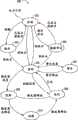
图1是根据本发明各个方面的电子武器系统的功能框图;FIG. 1 is a functional block diagram of an electronic weapon system in accordance with various aspects of the present invention;
图2A和2B是各种操作者接口和处理的状态图,每个处理支持图1的系统的操作者接口;2A and 2B are state diagrams of various operator interfaces and processes, each of which supports the operator interface of the system of FIG. 1;
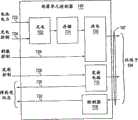
图3是可以在图1的系统中使用的采用根据本发明各个方面的另一实现方式的发射装置的功能框图;3 is a functional block diagram of a transmitting device employing another implementation in accordance with aspects of the present invention that may be used in the system of FIG. 1;
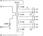
图4A至4D是图1的系统的端子或电极上的信号的信号定义图;4A to 4D are signal definition diagrams of signals on terminals or electrodes of the system of FIG. 1;
图5是图1的系统的枪实现方式的正面立体图;Figure 5 is a front perspective view of a gun implementation of the system of Figure 1;
图6是图1的系统的枪实现方式的背面立体图;Figure 6 is a rear perspective view of a gun implementation of the system of Figure 1;
图7是图1的系统的部署单元控制功能的功能框图;Fig. 7 is a functional block diagram of the deployment unit control function of the system of Fig. 1;
图8A和8B是图1的系统与目标的协作的模型的示意图;8A and 8B are schematic diagrams of a model of the collaboration of the system of FIG. 1 and a target;
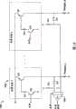
图9是图7的部署单元控制功能的一部分的示意图;Figure 9 is a schematic diagram of a portion of the deployment unit control functions of Figure 7;
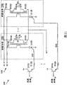
图10是图9的放电功能的一部分的示意图;Figure 10 is a schematic diagram of a portion of the discharge function of Figure 9;
图11至16是图9的放电功能的一部分的实现方式的示意图;以及11 to 16 are schematic diagrams of an implementation of a portion of the discharge function of FIG. 9; and
图17是用于图7至16的放电功能的刺激控制的开关的示意图。17 is a schematic diagram of a switch for stimulus control of the discharge function of FIGS. 7 to 16 .
具体实施方式Detailed ways
电子武器系统的更大效用和改进的准确度可以通过消除传统电子武器系统表现的一些问题来获得。一种传统的电子武器可以通过将武器的至少两个端子邻接(或使得靠近)于目标的皮肤或衣物,来执行制服动物或人(以下称为目标)的接触(或靠近)眩晕功能(也称为本地眩晕(local stun)功能)。另一种传统的电子武器可以通过从武器向目标发射一个或更多个系有导线的电极,使得这些电极靠近或刺入目标的皮肤或衣物,来执行制服目标的远程眩晕(remote stun)功能。在本地眩晕功能或远程眩晕功能中,形成电路,以将脉冲电流穿过目标的一部分组织,以妨碍目标的骨骼肌控制。当端子或电极靠近目标的组织时,在空气中形成电弧,从而形成完整的电路,使电流流过目标的组织。Greater utility and improved accuracy of electronic weapon systems may be obtained by eliminating some of the problems exhibited by conventional electronic weapon systems. A conventional electronic weapon can perform a contact (or proximity) stun function (also called a target) to subdue an animal or a person (hereinafter referred to as a target) by abutting (or bringing close to) at least two terminals of the weapon against the skin or clothing of the target. called the local stun function). another conventional electronic weapon can perform a remote stun function to subdue a target by firing one or more wire-tethered electrodes from the weapon at the target so that the electrodes approach or penetrate the target's skin or clothing . In a local stun function or a remote stun function, an electrical circuit is formed to pass pulsed currents through a portion of the target's tissue to impede the target's skeletal muscle control. When the terminals or electrodes are brought into close proximity to the target's tissue, an electric arc is formed in the air, which completes the electrical circuit and allows current to flow through the target's tissue.
根据本发明各个方面的电子武器系统可以可选地执行本地眩晕功能和远程眩晕功能,而不需要操作者介入以机械地改装电子武器系统。不管是否装载有弹药筒(用完了的或者未用完的),在武器系统的正面可以提供本地眩晕功能。在使用电子武器系统之前可以通过弹夹或弹匣单个地装载多个未用完的弹药筒,以提供多次远程眩晕功能的操作。Electronic weapon systems according to various aspects of the present invention can optionally perform local stun functions and remote stun functions without requiring operator intervention to mechanically modify the electronic weapon system. Regardless of whether a cartridge is loaded (spent or unspent), a local stun function may be provided on the front of the weapon system. Multiple unspent cartridges can be loaded individually by clip or magazine prior to engaging the electronic weapon system to provide multiple remote stun operations.
电极、系绳导线(tether wire)和推进系统传统地被封装为弹药筒,该弹药筒安装在电子武器上以形成用于单次远程眩晕的电子武器系统。在布置电极之后,用尽的弹药筒从电子武器中移除,并由另一个弹药筒替换。弹药筒可以包括若干电极,这些电极可作为一组一次发射,可按不同的时间作为多组发射,或者单个地发射。弹药筒可以具有若干组电极,每个组都用于以类似于弹匣(magazine)的方式独立发射。The electrodes, tether wire, and propulsion system are traditionally packaged as a cartridge that mounts on an electronic weapon to form an electronic weapon system for a single remote stun. After the electrodes are deployed, the spent cartridge is removed from the electronic weapon and replaced by another cartridge. A cartridge may include several electrodes which may be fired as a group at a time, as groups at different times, or individually. A cartridge may have several sets of electrodes, each set for independent firing in a magazine-like fashion.
根据本发明各个方面的电子武器系统保留有若干个随时可使用的弹药筒。例如,如果第一次尝试远程眩晕功能不成功(例如,电极错过目标或者电极短路),则可以使用第二弹药筒,而不需要操作员介入以机械地对电子武器系统进行再配置。若干个弹药筒可以同时安装(例如,作为弹夹或者弹匣),或依次安装(例如,可以移去任何弹药筒并单独地替换为其他弹药筒)。Electronic weapon systems according to aspects of the present invention maintain a number of cartridges ready for use. For example, if a first attempt at a remote stun function is unsuccessful (eg, electrodes miss target or electrodes short), a second cartridge may be used without requiring operator intervention to mechanically reconfigure the electronic weapon system. Several cartridges may be mounted simultaneously (eg, as clips or magazines), or sequentially (eg, any cartridge may be removed and replaced with other cartridges individually).
远程眩晕功能的准确度依赖于从电子武器发射出去的每个电极的可重复弹道,以及其他因素。传统的弹药筒包括用于在投掷之前保持电极和在部署早期导引电极的投掷腔。传统上,部署是通过气体的突然释放(例如,产生烟火气体或者压缩气体缸的破裂)来实现的。电极和投掷腔通过被严密覆盖而保持无污染。当部署电极时,其从导线库(wire store)拉其导线系绳(wire tether),因此在飞行时导线系绳在电极后面延伸到武器。The accuracy of the remote stun function depends on the repeatable trajectory of each electrode fired from the electronic weapon, among other factors. Conventional cartridges include a throw chamber for holding the electrode prior to throw and guiding the electrode early in deployment. Traditionally, deployment has been achieved by a sudden release of gas (eg, generation of pyrotechnic gases or rupture of compressed gas cylinders). The electrodes and throw chamber are kept free from contamination by being tightly covered. When the electrode is deployed, it pulls its wire tether from the wire store, so the wire tether extends behind the electrode to the weapon when in flight.
传统的弹药筒可以被构造成提供适当的有效距离范围。当目标位于距武器特定距离范围内(例如从大约6到大约15尺(2米到5米))时,有效距离范围提供影响目标的适合的电极展度(spread)(例如,大于大约6英寸(15厘米))。Conventional cartridges can be configured to provide a suitable range of effective distances. The effective range provides a suitable electrode spread (e.g., greater than about 6 inches) to affect the target when the target is within a specific distance range from the weapon (e.g., from about 6 to about 15 feet (2 m to 5 m) (15 cm)).
根据本发明各个方面的电子武器系统支持使用一组弹药筒,每个弹药筒都具有不同的有效距离范围,这部分地是由于每个弹药筒(或者弹匣)为武器提供不同的性能指示(或者可以确定其性能的代码)。弹药筒、弹夹和弹匣是通常被称为部署单元的设备的特定例子。电子武器系统可以被操作以发射适于远程眩晕功能的特定应用的特定弹药筒(或者具有若干组电极的弹药筒的特定电极组)。Electronic weapon systems in accordance with aspects of the present invention support the use of a set of cartridges, each having a different range of effective distances, due in part to the fact that each cartridge (or magazine) provides a different performance indication to the weapon ( or code whose performance can be determined). Cartridges, clips and magazines are specific examples of devices commonly referred to as deployment units. An electronic weapon system may be operated to fire a specific cartridge (or a specific set of electrodes for a cartridge with sets of electrodes) suitable for a specific application of a remote stun function.
如上所述的更大效用和/或改善的准确度是通过根据本发明各个方面构造和操作的电子武器系统来实现的。作为示例并且为了清楚的介绍,考虑附图1-15的电子武器系统100。电子武器系统100包括与一组(或者多个)弹药筒104协作的发射装置102。弹药筒104可以是分开的多个单元或者多个弹药筒的机械组装件。在任一种结构中,所述的多个单元或多个弹药筒在这里称为部署单元104。部署单元104包括一组弹药筒105和106,这些弹药筒可分别或者作为一组安装到发射装置102上,例如,安装在一个或更多个弹夹或弹匣中。部署单元104可以包括2个或更多个弹药筒(例如,3、4、5、6或更多个)。当每个弹药筒都用尽时,弹药筒可以单个地替换。在部署单元104中的弹药筒可以相同或不同(例如,在性能、制造商、制造日期以及其他方面不同)。Greater utility and/or improved accuracy as described above is achieved by an electronic weapon system constructed and operative in accordance with various aspects of the present invention. As an example and for clarity of presentation, consider
发射装置包括任何用于操作一个或更多个部署单元的装置。发射装置可以被封装为接触眩晕装置、警棍、盾、眩晕枪、手枪、步枪、迫击炮(mortar)、手榴弹、投射弹(projectile)、地雷、或者区域保护装置。例如,一种枪型发射装置可以由操作者手持以每次从一组弹药筒或者弹药筒弹匣中操作一个或更多个弹药筒。地雷型发射装置(还称为区域遏制(area denail)装置)可以被遥控(或者由如伴线(trip wire)这样的传感器操作)以基本同时发射一个或更多个弹药筒。手榴弹型发射装置可以用计时器操作以基本同时发射一个或更多个弹药筒。投射弹型发射装置可以用计时器或者目标传感器操作以将多个电极组发射到多个目标。这些各种发射装置的功能可以从适用于这些发射装置的功能框图中理解。例如,附图1的功能框图示出了发射装置102,其包括控制器120、显示器122、数据通信装置124、专用功能126、处理电路130、和部署单元控制器140。部署单元控制器140包括具有检测器功能143(例如,具有一个或更多个检测器)的配置报告功能142、发射控制功能144、和刺激信号发生器146。发射装置102的各组件协作以提供上述的所有功能。少于所有这些功能的其他组合可以根据本发明来实现。根据本发明各个方面的实现方式中的部署单元104可以包括一个或更多个弹药筒、一个或更多个弹匣、和/或一个或更多个弹药筒的弹夹。根据本发明各个方面的武器系统可以包括一个或更多个物理分离的部署单元,例如用于冗余、备份,或者作为覆盖一个区域的阵列。A launch device includes any device for operating one or more deployment units. The launch device may be packaged as a contact stun device, baton, shield, stun gun, pistol, rifle, mortar, grenade, projectile, mine, or area protection device. For example, a gun-type firing device may be held by an operator to operate one or more cartridges at a time from a set of cartridges or a cartridge magazine. Mine-type launchers (also known as area denial devices) can be remotely controlled (or operated by sensors such as trip wires) to fire one or more cartridges substantially simultaneously. The grenade-type launcher may be timer-operated to fire one or more cartridges substantially simultaneously. Projectile-type launchers may operate with timers or target sensors to launch multiple electrode sets to multiple targets. The functions of these various transmitting devices can be understood from the functional block diagrams applicable to these transmitting devices. For example, the functional block diagram of FIG. 1 shows launch device 102 including
发射装置102经由电气接口107与部署单元104的每个弹药筒105和106相通信。通过接口107,发射装置102可以为每个弹药筒提供电力、发射控制信号、和刺激信号。这些信号中的各个信号对于每个弹药筒来说可以是共用的或者(优选的是)唯一的。每个弹药筒105和106可以向发射装置102提供传达指示(例如,性能指示)的信号,如上所述且在下文中将进一步说明。Launching device 102 communicates with each
如上所述的各种形式的发射装置102包括由目标(例如,区域遏制装置(areadenial device)、由操作者(例如,手枪型装置)、或者由定时电路或者传感器电路(例如,手榴弹型装置)操作的控制器。控制器包括任何传统的手动或者自动接口电路,如手动开关或者继电器。控制器可以利用图形用户界面(例如,图形显示器、点击装置或者触摸屏显示器)来实现。The various forms of launching device 102 described above include those launched by a target (e.g., an area denial device), by an operator (e.g., a pistol-type device), or by a timing or sensor circuit (e.g., a grenade-type device). A controller for operation. The controller includes any conventional manual or automatic interface circuit, such as a manual switch or relay. The controller can be implemented using a graphical user interface (eg, a graphical display, pointing device, or touch screen display).
对于手枪型装置,控制器120可以包括保险控制器(safetycontrol)、触发器控制器(trigger control)、射程优先级控制器(range priority control)、和刺激控制器(stimulate control)中的任何一个或更多个。所述保险控制器(例如,二元开关)可以由处理电路130读取并实现触发器和刺激电路(144,146)的启动或者停用。所述触发器控制器可以由处理电路130读取以实现在特定弹药筒(105)中的推进器(116)的操作(144)。射程优先级控制器可以由处理电路130读取,且实现由弹药筒的处理器进行的选择,以根据由射程优先级控制器指示的预定应用的有效距离范围,响应于触发器控制器的下一操作进行操作。当操作时,刺激控制器可以引发经由发射装置102的端子(未示出)或者经由弹药筒105的接触器118对用于本地眩晕功能的另一个或更多个刺激信号的另一次递送。接触器118可以经由本地眩晕功能的端子或者经由远程眩晕功能的电极递送附加的刺激信号。For a pistol-type device, the
控制器可以利用在这里论述的任何指示器/检测器来实现。这种实现可以便于保持发射装置的密封件。例如,保险控制器、触发器控制器、射程优先级控制器、和/或刺激控制器可以通过磁体实现,该磁体与控制器的手动移动部分一起移动,且位于发射装置的密封件内的舌簧(reed)开关对磁体的位置和/或移动进行检测。The controller can be implemented with any of the indicators/detectors discussed herein. Such an implementation may facilitate maintaining the seal of the launch device. For example, the safety controller, trigger controller, range priority controller, and/or stimulus controller can be implemented by magnets that move with the manually movable portion of the controller and are located on a tongue within the seal of the firing device. A reed switch senses the position and/or movement of the magnet.
显示器提供信息的呈现并且可进一步呈现如上所述的控制器的图标。可以使用任何常规显示器。例如,显示器122从处理电路130接收信息,给发射装置102的操作者呈现所述信息,并可以接收传回处理电路130的输入(例如,触摸屏功能)。The display provides the presentation of information and may further present icons for the controller as described above. Any conventional display can be used. For example,
数据通信功能利用任何传统的协议和电路执行有线的和/或无线的数据发送和接收。通过数据通信,处理电路130可以接收由处理电路130执行的软件,并且可以报告用于显示器122的呈现、描述发射装置102和/或部署单元104的更新后的配置信息以及由数据处理电路130收集的数据。The data communications function performs wired and/or wireless data transmission and reception using any conventional protocols and circuits. Through data communications,
专用功能与处理电路130相通信,以在特定的应用或者特定类型的应用中使得便于更有效地使用发射装置102。专用功能126可以提供软件给处理电路130,并且包括传感器和I/O装置。警告、本地眩晕和远程眩晕功能在此被称为基本功能。Special purpose functions are in communication with
处理电路包括根据存储的程序执行功能的任何电路。例如,处理电路130可以包括处理器和存储器,和/或执行来自存储器的微码(microcode)或者汇编语言指令的传统时序机。处理电路可以包括一个或更多个微处理器、微控制器、专用集成电路、数字信号处理器、可编程门阵列、或者可编程逻辑器件。Processing circuitry includes any circuitry that performs a function according to a stored program. For example,
配置报告功能包括任何收集描述电子武器系统的操作状态和配置的信息的功能。所收集的信息可以是由配置报告功能或者由其他电路或处理器执行的功能测试的结果。所收集的信息可以由配置报告功能报告,或者简单地使得可以由配置报告功能提供给其他功能(例如,数据通信功能124、处理电路130、存储器114)。例如,部署单元140的配置报告功能142包括检测器143,其与指示器协作或者与部署单元的指示器(例如,弹药筒105和106的指示器)执行数据通信并向处理电路130报告结果。处理电路130可以使用这些结果,以利用一个或更多个部署单元104的适合部分恰当地执行任何警告、本地眩晕和远程眩晕功能。此外,处理电路130可以与数据通信功能124和/或部署单元控制功能140相互作用,以将收集的信息传输到其他系统或部署单元的存储器。Configuration reporting functions include any function that collects information describing the operational status and configuration of an electronic weapon system. The information collected may be the result of configuration reporting functions or functional tests performed by other circuits or processors. The collected information may be reported by the configuration reporting function, or simply made available to other functions (eg, data communication function 124,
例如,可以在弹药筒105部署前或紧随其后优选地利用功能试验结果来收集发射装置102的配置和当前安装的部署单元的描述,并将其存储在存储器114中。可以(例如按特定日期、时间、操作者和/或位置)将该收集信息与特定主要功能结合音频、视频以及其他数据一起关联起来,然后立即或者在合适的时间通过数据通信功能124(例如,在操作者移动的末端)传送该收集信息。For example, a description of the configuration of the launch device 102 and the currently installed deployment unit may be collected and stored in the memory 114 prior to or immediately following deployment of the
检测器如上所述与一个或更多个指示器相通信。例如,检测器143可以包括独立传感器以检测部署单元的每个弹药筒的各指示器112。在一个实现方式中,检测器143包括具有舌簧继电器的电路,以感测如下的磁体(或者磁通电路)的存在:该磁体(或者磁通电路)在一个或更多个靠近弹药筒105的位置具有适当的极性和/或强度。所述位置可以定义如上所述的代码,该代码由检测器143检测并由处理电路130读取以用于管理电子武器系统100的操作。部署单元可以具有多个指示器(例如,用于每个弹药筒的一组指示器)。检测器可以具有相应的多个传感器(例如,舌簧继电器)。The detector communicates with one or more indicators as described above. For example,
发射控制功能提供足以激活推进器的信号。例如发射控制功能144提供用于操作电点火烟火引爆物(primer)的电信号。接口107可以由每个推进器116的一个引线(conductor)(例如,销(pin))和穿过推进器116的本体、弹药筒105的本体和/或发射装置102的本体的返回电通路来实现。The launch control function provides a signal sufficient to activate the thrusters. For example, the launch control function 144 provides electrical signals for operating an electrically ignited pyrotechnic primer. The
刺激信号发生器包括用于生成刺激信号的电路,以使电流通过目标的组织以使目标疼痛顺应(compliance)和/或妨碍目标骨骼肌的动作。可以使用任何传统的刺激信号。例如,在一种实现方式中刺激信号发生器146可以每秒19个脉冲的频率递送大约5秒钟,每个脉冲在大约100微秒内传递大约100微库仑的电荷通过目标的组织。在其他的实现方式中,刺激信号发生器146提供如下文所述的刺激程序。刺激信号发生器146可以具有对部署单元104的所有弹药筒的并行的(例如同时操作)共同接口,或者可对每个弹药筒105、106(如图所示)具有单个独立操作接口。The stimulation signal generator includes circuitry for generating stimulation signals to pass electrical current through tissue of the target to cause pain compliance of the target and/or impede action of the skeletal muscle of the target. Any conventional stimulus can be used. For example, in one implementation the
在结构上根据本发明各个方面的发射装置102发射部署单元104的任何一个或更多个电极并提供刺激信号给用于远程眩晕功能的任何电极组合。例如,发射控制功能144可以提供唯一的信号到数个接口107中的每一个,部署单元的每个弹药筒具有一个独立操作的接口107。刺激信号发生器146可以提供唯一的信号到数组电极中的每一组,部署单元的每个弹药筒具有一个独立操作的端子组。在一种实现方式中,发射装置102通过将刺激信号发生器146连接到位于发射装置的一个面的任何一个或更多个端子以提供本地眩晕功能。根据本发明的各个方面,这种端子与弹药筒的导线库配合以激活用于远程眩晕功能的弹药筒电极。Transmitting device 102 , constructed in accordance with various aspects of the present invention, transmits any one or more electrodes of
具有这种发射装置和部署单元的电子武器系统的操作便于多重功能操作。例如,一组电极可以首先部署用于远程眩晕功能,随后(例如,未用完的弹药筒的)一组端子可以用于本地眩晕功能或者用于显示电弧(例如,可听和/或可视警告)。当已经部署超过一组电极用于远程眩晕功能时,可以对选定的目标或者多个目标执行远程眩晕功能(例如在电极中的快速序列中提供的刺激信号或者同时为多个电极提供的刺激信号)。Operation of an electronic weapon system with such launchers and deployment units facilitates multifunctional operations. For example, a set of electrodes may be deployed first for a remote stun function, and then a set of terminals (e.g., of an unspent cartridge) may be used for a local stun function or to indicate an arc (e.g., audibly and/or visually). warn). When more than one set of electrodes has been deployed for the remote stun function, the remote stun function can be performed on a selected target or multiple targets (such as stimulation signals provided in a rapid sequence among the electrodes or stimulation provided to multiple electrodes simultaneously Signal).
弹药筒包括一个或更多个系着导线的电极、用于各电极的导线库、和推进器。细导线有时称为纤丝(filament)。当将具有弹药筒的部署单元安装到发射装置102时,发射装置102确定部署单元的至少一个弹药筒(优选的是所有弹药筒)的能力。发射装置102可以写入待由弹药筒存储的信息(例如,发射装置的标识、操作者标识、发射装置的配置、发射装置的GPS位置、日期/时间、所执行的主要功能等等)。The cartridge includes one or more wire-tethered electrodes, a wire bank for each electrode, and a pusher. Thin wires are sometimes called filaments. When a deployment unit having cartridges is mounted to launch device 102, launch device 102 determines the capabilities of at least one cartridge, preferably all cartridges, of the deployment unit. The launch device 102 may write information to be stored by the cartridge (eg, launch device identification, operator identification, launch device configuration, launch device GPS location, date/time, primary function performed, etc.).
在发射装置102的控制器120操作时,发射装置102为本地眩晕功能提供刺激信号。在发射装置102的另一控制器120操作时,发射装置102提供发射信号给部署单元104的将被发射的一个或更多个弹药筒,并可以为每个弹药筒提供刺激信号以用于远程眩晕功能。可以参考所安装的弹药筒的能力和/或操作者的控制操作,由发射装置102来实现对发射哪个(哪些)弹药筒的确定。根据本发明的各个方面,发射信号具有基本上小于刺激信号电压的电压;并且,可以根据发射装置102的控制器120和/或根据发射装置102的配置同时提供或者分别提供发射信号和刺激信号。When the
如上所述,弹药筒包括具有一个或更多个系着导线的电极的任意一次性封装。因而,弹匣或者弹夹是弹药筒的一种类型。根据本发明的各个方面,附图1中的弹药筒105(106)包括接口107、指示器112、存储器114、推进器116、和接触器118。在另一实现方式中,省略了指示器112,存储器114执行提供任何获者所有以下参考指示器112论述的指示的功能。在另一实现方式中,为降低弹药筒的成本和复杂性,省略了存储器114。As noted above, the cartridge includes any disposable package having one or more lead-attached electrodes. Thus, a magazine or clip is a type of cartridge. Cartridge 105 ( 106 ) in FIG. 1 includes
接口107支持任何传统方式和如在此讨论的通信。接口107可以包括用于通信的机械和/或电结构。通信可以包括传导电信号(例如,连接器、放电间隙)、支持磁路、和传递光信号。
指示器包括向发射装置提供信息的任何装置。指示器与发射装置协作,以对将信息从指示器传送到发射装置的标记(indicia)进行自动通信。信息可以任何传统的方式传送,包括由指示器提供信号或者由指示器对由发射装置提供的信号进行调制。信息可以借助于通信信号的任何传统的特性来传送。例如,指示器112可以包括无源的电路、磁路、或光路或者组件以影响源自发射装置102的电荷、电流、电场、磁场、磁通量或者辐射(例如,光)。电荷、电流、场、通量或者辐射在特定时间的存在(或者不存在)可用来经由接口107传送信息。指示器在发射装置102中相对于检测器的相对位置可以传送信息。在各种实现方式中,指示器可以包括一个或更多个任何以下的部分:电阻、电容、电感、磁体、磁分路器(magnetic shunt)、谐振电路、滤波器、光纤、反射面和存储装置。An indicator includes any device that provides information to a transmitting device. The pointer cooperates with the launch device for automatic communication of an indicia that conveys information from the pointer to the launch device. Information may be conveyed in any conventional manner, including by the indicator providing a signal or by the indicator modulating a signal provided by the transmitting device. Information may be conveyed by means of any conventional nature of communication signals. For example,
在一种实现方式中,指示器112包括传统的无源射频识别标签电路(例如,具有天线或者用作天线)。在另一实现方式中,指示器112包括镜像表面或者透镜,其将源自发射装置102的光转向到发射装置102的检测器预定位置或者敏感区域。在另一实现方式中,指示器112包括磁体,其位置和极性由发射装置102(例如经由一个或更多个舌簧开关)来检测。在又一实现方式中,指示器112包括磁路的一个或更多个部分,其存在性和/或相对位置可由发射装置102中的磁路的其余部分来检测。在另一实现方式中,指示器112由传统的连接器(例如,销和插座)耦合到发射装置102。指示器112可以包括阻抗,发射装置102提供的电流通过所述阻抗。为简单起见,该后一方法是优选的,但在被污染的环境下可能较不可靠。In one implementation,
各种实施例中的指示器112包括任何上述通信技术的组合。指示器112可以利用模拟和/或数字技术进行通信。当需要传送超过一比特的信息时,通信可以是串行的、时分复用的、频分复用的、或者并行通信的(例如,多个技术或同一技术的多个信道)。
指示器112指示的信息可以以编码方式(例如,模拟值传送数字代码,通信值传送针对发射装置的表的索引,该表更充分地描述了代码的含义)通信。所述信息可以包括部署单元和/或弹药筒105的描述,例如包括:可以从该弹药筒获得的使用量(例如,一个、多个、剩余量)(例如,可以与弹药筒中的电极对数量相对应);每个远程眩晕使用的有效射程范围,无论弹药筒是否准备好下次远程眩晕使用(例如,弹药筒完全用尽的指示);所有或者下次远程眩晕使用的有效射程范围;弹药筒的制造商;弹药筒的制造日期;弹药筒的能力;弹药筒的无能;弹药筒型号识别符;弹药筒的序号;与发射装置型号的兼容性;弹药筒的安装取向(例如,在可以采用多个取向、每个取向具有不同的能力(例如,有效距离)的情况下);和/或存储在存储器114中的任何值(例如,由制造商存储的值、当将弹药筒与特定发射装置安装在一起时由任何发射装置存储的值)。The information indicated by the
存储器包括任何的模拟或者数字信息存储装置。例如,存储器114可以包括任何传统的非易失性半导体、磁或者光存储器。存储器114可以包括任何如上所述的信息并且可以进一步包括将要由发射装置102执行的任何软件。软件可以包括用于该特定弹药筒的驱动程序,以便于指示器112、推进器116、和/或接触器118的适当的操作(例如即插即用)。这种功能性可以包括专用于弹药筒的用途的刺激信号,该用途被提供给该弹药筒以实现该用途。例如,一个发射装置可以适合于四种类型的弹药筒:军事的、执法的、商业安全的和平民个人防卫的,且根据从存储器114读取的软件采用特定的发射控制信号或者刺激信号。Memory includes any analog or digital information storage device. For example, memory 114 may include any conventional non-volatile semiconductor, magnetic or optical memory. Memory 114 may include any of the information described above and may further include any software to be executed by transmitting device 102 . The software may include drivers for that particular cartridge to facilitate proper operation of the
推进器将电极推离发射装置并推向目标。例如,推进器116可以包括压缩气体容器,其打开后通过从容器中逃逸的膨胀气体从弹药筒105朝向目标(未示出)驱动电极。推进器116可以附加地或者另选地包括传统的烟火气体发生能力(例如,火药、无烟手枪火药)。优选地,推进器116包括电使能焰火引爆物,其与由接触器118传送的刺激信号相比在相对低的电压(例如:小于约1500伏)下进行操作。Thrusters push the electrodes away from the launcher and toward the target. For example, pusher 116 may comprise a container of compressed gas which, when opened, drives the electrode from
接触器使刺激信号接近或者接触目标(例如,动物或者人)的组织。接触器118可以执行如上所述的本地眩晕功能和远程眩晕功能。对于远程眩晕功能,接触器118包括由推进器116推离弹药筒105的电极。接触器118提供发射装置102中的刺激信号发生器146和用于本地眩晕功能的端子之间的电连接。接触器118还提供发射装置102中的刺激信号发生器146和用于远程眩晕功能的每个电极的导线系绳的俘获端(captive end)之间的电连接。接触器118从接口107接收刺激控制信号,且可以进一步包括刺激信号发生器(例如,以补充或者替换发射装置102的刺激信号发生器146)。The contactor brings the stimulation signal close to or in contact with tissue of a target (eg, animal or human). The
发射装置102和一个或更多个部署单元(例如,弹匣或者弹药筒)之间的接口107中的信号可以与如以上参照图1所讨论的在发射装置和弹药筒之间的通信相同、基本相似或者类似。The signals in the
根据本发明各个方面的电子武器系统的另一实施例用如上所述的弹匣进行操作。弹匣可以包括具有多个弹药筒的封装或者包括具有多个弹药筒的功能而不将每个弹药筒封装为可分离单元的封装。此外,弹匣可以为弹匣中的所有电极提供一些共有的功能(例如,共有的推进系统、指示器或者存储功能)。Another embodiment of an electronic weapon system according to aspects of the invention operates with a magazine as described above. A magazine may include a package with multiple cartridges or a package with the functionality of multiple cartridges without packaging each cartridge as a separable unit. Additionally, the magazine may provide some common functionality (eg, a common propulsion system, indicator, or storage function) for all electrodes in the magazine.
弹匣为多个弹药筒提供机械支撑且可进一步为其提供通信支持。除了省略了指示器112和存储器114以外,用在弹匣中的弹药筒在结构上和功能上可以与如上所述的弹药筒105相同。弹匣可以针对作为弹匣的一部分的所有弹药筒实现所述指示器和存储功能。弹匣的指示器和/或存储器可以存储或者传送关于多个安装、弹药筒和使用的信息。由于这样的弹匣可以再装填弹药筒,且可安装/移去/重新安装到若干发射装置上,当检测到变化或者在适当的时间(例如,在作为远程眩晕功能的使用时记录变化时),日期、时间、弹药筒的描述和发射装置的描述可以被检测、指示、存储和/或取回。使用量可以被记录,以便于定期维护、担保范围(warrantycoverage)、失效分析或者替换。The magazine provides mechanical support for multiple cartridges and may further provide communications support for them. The cartridge used in the magazine may be structurally and functionally identical to the
根据本发明的各个方面的电子武器系统可以包括用于发射控制和刺激信号传送的独立的电接口。单发(single shot)弹药筒的发射控制接口可以包括一个信号和地线。发射控制信号可以是相对低电压的二进制信号。无论弹药筒是否安装在发射装置上,可以为本地眩晕功能单独提供刺激信号。可以在弹药筒推进器已经被激活之后为远程眩晕功能提供刺激信号。Electronic weapon systems according to aspects of the invention may include separate electrical interfaces for launch control and stimulus signal transmission. The launch control interface for single shot cartridges may include a signal and ground wire. The transmit control signal may be a relatively low voltage binary signal. A separate stimulus signal can be provided for the local stun function, regardless of whether the cartridge is mounted on the launcher. A stimulus signal may be provided for the remote stun function after the cartridge advancer has been activated.
部署单元可以包括用于警告功能和/或本地眩晕功能的若干(例如,2个或更多)组端子,和分别用于远程眩晕功能的若干(例如2个或更多)组电极。一个组可以包括两个或更多端子或者电极。电极的发射可以是单个的(例如,当目标太近,以至于电极在飞行时无法充分分开时,单个发射可以有利于有效的点射(placement))或者作为一组(例如,按快速接连的方式或者同时的方式发射)。在一个实现方式中,将一组端子和一组电极封装为弹药筒,部署单元包括若干这样的弹药筒。在弹药筒的电极发射之前,电子武器的一组端子(例如,发射装置的一部分或者弹药筒的一部分)可以执行显示(例如,警告)功能或者本地眩晕功能。在一个实现方式中,在发射之后,只有远程眩晕功能从用尽的弹药筒执行;其他的弹药筒对于本地眩晕或者显示功能是可用的。因为部署单元包括不只一个的弹药筒,且每个弹药筒具有独立的接口,因此部署单元使得便于执行如上所述的多重功能。The deployment unit may comprise several (eg, 2 or more) sets of terminals for the warning function and/or the local stun function, and several (eg, 2 or more) sets of electrodes for the remote stun function, respectively. A group may include two or more terminals or electrodes. The firing of the electrodes may be individual (e.g., a single firing may facilitate effective placement when the target is too close for the electrodes to be sufficiently separated in flight) or as a group (e.g., in rapid succession Or launch simultaneously). In one implementation, a set of terminals and a set of electrodes are packaged as a cartridge, and the deployment unit includes several such cartridges. A set of terminals of the electronic weapon (eg, part of the firing device or part of the cartridge) may perform a display (eg, warning) function or a local stun function before the electrodes of the cartridge are fired. In one implementation, after firing, only the remote stun function is performed from the spent cartridge; other cartridges are available for local stun or display functions. Because the deployment unit includes more than one cartridge, each cartridge having an independent interface, the deployment unit facilitates the performance of multiple functions as described above.
例如,在这样的部署单元的第一弹药筒已经朝向第一目标被部署后,刺激信号发生器146可以操作以用部署单元的其他端子提供警告功能或者本地眩晕功能。第二目标可以预留给第二远程眩晕功能。随后,部署单元的其他端子可以用于另一警告功能或者本地眩晕功能。部署单元可包括独立于(例如,无一、一些或者所有已安装的;无一、一些或者所有已用尽的)弹药筒结构的端子以用于警告和/或本地眩晕功能。For example, after a first cartridge of such a deployment unit has been deployed towards a first target, the
根据本发明的各个方面的电子武器系统提供操作者接口以便于使用系统的多重功能。操作者接口包括由处理器执行的方法和由操作者执行的方法。例如,附图1的处理电路130为附图2A的操作者接口200执行状态改变方法。在状态改变方法中,一次只有一个状态,如显示为椭圆的,是活动的。为了从一种状态前进到另一种状态,必须满足在离开当前状态到达下一状态的箭头上规定的准则。换言之,当满足准则时,方法的状态改变到下一个状态。当所述方法当前处在特定的状态时,执行对于该特定状态来说唯一的动作。由处理电路130感测的控制包括保险(开/关)、触发器(设置/释放)、刺激(设置/释放)和警告(设置/释放)。An electronic weapon system according to various aspects of the present invention provides an operator interface to facilitate access to multiple functions of the system. The operator interface includes methods executed by the processor and methods executed by an operator. For example,
在一种实现方式中,刺激和警告控制器是作为一个控制器一起实现的,且用于本地眩晕功能的一个端子充当报警装置。当没有目标接近端子时,用于本地眩晕功能的端子将随着砰的一声响亮的声音而显示可见弧。如果“设置”激活警告和刺激并且如果“释放”激活警告和刺激,则实现组合的刺激和警告控制器。In one implementation, the stimulation and warning controllers are implemented together as one controller, and one terminal for the local stun function acts as an alarm device. Terminals for the local stun function will display a visible arc with a loud bang when no targets are approaching the terminal. A combined stimulus and warning controller is implemented if "set" activates warning and stimulus and if "release" activates warning and stimulus.
响应于对电力(例如,所连接的电池电力)施加的检测,由处理电路130执行的操作者接口在休眠状态202下开始操作。在耗能最小时,在休眠状态202下只执行紧要的功能(例如,维护时间与日期、维护非易失性存储器的内容、感测特定的控制)以节省电池电力。可以在不激活处理电路130的处理器的情况下执行紧要的功能。当感测到使用保险关闭的控制器时,操作者接口200前进到报告状态204。在状态204下可以将处理电路130保持的或其可以获得的任何各种信息报告给操作者。操作者可操作其他传统控制器(例如,超文本链接或菜单项)以接收附加的或不同的报告并且/或者指定新的或改变的配置首选参数。在状态204中报告可持续,直到检测到保险控制器的结束或变化。如果操作者指示报告已完成或者如果经过一段时间控制器没有进一步的变化,操作者接口200往回前进到休眠状态202。In response to detection of application of power (eg, connected battery power), the operator interface executed by the
响应于检测到数据通信功能124的活动数据通信信号或者部署单元((例如,指示器或者存储器)期望与其进行数据通信)的安装或移除的变化,操作者接口200可以离开休眠状态202并前进到数据传送状态205。根据任何适当协议的数据传送可以在状态205下继续,直到检测到保险控制器的完成或变化。当接收到新的软件时,电子武器系统的配置可以自动地改变到安装和/或运行所接收的软件。操作者接口200可以通过所接收的软件的操作而被修改或者替换。假定没有这样的修改或者替换,如果数据通信被放弃或已完成或者如果经过一段时间控制没有进一步的变化,则操作者接口200往回前进到休眠状态。In response to detecting a change in the active data communication signal of the data communication function 124 or the installation or removal of a deployment unit (e.g., a pointer or memory) with which data communication is desired, the
响应于检测到保险控制器处于“关闭”状态,操作者接口200从状态202、204或者205前进到待命状态206。从待命状态206可以引发任何基本功能。电子武器系统的能力可以顺序显示或者根据传统的操作者控制请求的那样(例如,剩余电池容量,用于下一次远程眩晕操作的可用弹药筒射程或为下一次远程眩晕操作选择的弹药筒射程)而显示。
响应于检测到警告控制器设置,操作者接口200从待命状态206前进到警告状态207。在状态207,任何适当的可听或者可视警告电路可以被激活。在一种实现方式中,可听警告直接向目标发出命令,比如“站住!放下你的武器!举起手来!”。如上所述,刺激信号发生器可以在端子之间提供警告、大声的、可视电弧,以用于本地眩晕功能。当释放了警告控制器时,操作者接口200往回前进到待命状态。In response to detecting the warning controller setting,
响应于检测到触发器控制器设置,操作者接口200从待命状态前进到发射状态208,按照电子武器系统进入发射状态208之前的配置所规定的那样立即从一个或更多个弹药筒发射一个或更多个电极。如果触发器控制器立即被释放,操作者接口200从发射状态208前进到运行状态209。如果不是(例如,经过适当的时间并且触发器控制器没有被释放),那么操作者接口200从发射状态208前进到延续(stretch)状态210。In response to detecting the trigger controller setting, the
在另一个例子中,附图1的处理电路130为附图2B的操作者接口250执行状态改变方法。操作者接口250包括如上所述的休眠状态202、发射状态208、和运行状态209。接口250可以进一步包括如上所述的报告状态204、数据传送状态205、警告状态207和延续状态210(未示出)。特别地,操作者接口250包括待命发射状态252、待命刺激状态254、运行状态256和运行状态258。除了如下文论述的往返于运行状态256和258的不同状态转移以外,运行状态256和258参考运行状态209执行以上讨述的功能。In another example,
响应于检测到保险控制器处在“关闭”状态,操作者接口250从休眠状态202前进到待命发射状态252。响应于检测到触发器控制器设置,操作者接口250从待命发射状态252前进到发射状态208,于是电极如文中所述的那样被发射;且,当触发器控制器被释放时,操作在运行状态209下继续,于是产生刺激电流传导通过目标的组织,直到完成。当状态209的运行功能完成时,操作者接口250前进到待命刺激状态254。In response to detecting that the safety controller is in the “OFF” state,
当处于待命刺激状态254时,刺激控制器的操作将操作推进到运行状态258。当处于待命刺激状态254时,触发器控制器的操作提供状态256下的后续运行操作,然而,当状态256的运行操作完成时,操作者接口250回到待命刺激状态254。只有在刺激控制器的至少一次操作之后,才会发生随后的发射。该策略是通过响应于刺激控制器的操作从状态254或者状态256前进到运行状态258来实现的。While in the
在运行状态258下,当状态258的运行操作完成时,操作者接口250前进到待命发射状态252。In the
在运行状态258下,当触发器控制器被设置时,操作者接口250前进到发射状态208。In the
如果感测到保险控制器处在“开”状态,操作者接口250从待命发射状态252或者运行状态258(如图所示)前进到休眠状态202;和从包括运行状态256、运行状态209的其他状态(未示出)前进到待命刺激状态254。If the safety controller is sensed to be in the "on" state, the
根据本发明的各个方面的刺激信号用于确保使目标顺应电子武器系统的操作者的意图。根据本发明各个方面的多重功能武器为操作者提供了便利性,以在不同应用中以不同的刺激信号确保顺应性。顺应性可以是目标感觉的疼痛和/或妨碍目标使用其骨骼肌的结果。作为第一个例子,对抗目标以获得顺应的武力可以相对大于对抗当事人(client)以维持顺应的武力。在该第一例子中合适的刺激信号可以包括攻击(strike)阶段(stage)和随后的任意数量的保持阶段。保持阶段的能量消耗可少于攻击阶段的能量消耗。作为第二个例子,对抗目标的初始武力可适当小于对抗想抵制顺应的目标的后续武力。在该第二例子中合适的刺激信号可包括任意数量的保持阶段和随后的一个或更多个攻击阶段。为多种应用,操作者可得到不同能量消耗的攻击阶段和保持阶段。例如,在所述阶段中,阶段的持续时间可以由操作者调节。Stimulus signals according to various aspects of the present invention are used to ensure compliance of the target with the intention of the operator of the electronic weapon system. A multifunctional weapon according to various aspects of the present invention provides the convenience for the operator to ensure compliance with different stimulation signals in different applications. Compliance may be the result of pain felt by the target and/or interference with the target's use of its skeletal muscles. As a first example, the force against a target to achieve compliance may be relatively greater than the force against a client to maintain compliance. A suitable stimulus signal in this first example may include a strike stage followed by any number of hold stages. The energy consumption in the hold phase can be less than that in the attack phase. As a second example, the initial force against a target may be suitably smaller than the follow-up force against a target that wants to resist compliance. A suitable stimulus signal in this second example may include any number of hold phases followed by one or more attack phases. For various applications, the operator can obtain attack phases and hold phases with different power consumption. For example, in said phases, the duration of the phases may be adjusted by an operator.
如上所述,如果触发器控制器没有释放,阶段的持续时间可能在延续状态210下从初始持续时间延伸,直到最长持续时间。初始持续时间可以是制造厂设置、用户可配置的设置、或者最近的延续持续时间。显示器可以报告包括延长部分在内的剩余持续时间,并在触发器控制器保持不释放同时进行计时。希望将阶段延长例如25秒的操作者,可以监视显示器,从大概5秒进行到25秒,然后释放触发器控制器。任何袭击阶段或者保持阶段都可以延长。如附图2所示,通过触发器控制器的操作将发射之后执行的第一阶段延长。As mentioned above, if the trigger controller is not released, the duration of the phase may be extended in the
在根据本发明各个方面的其他实现方式中,可以使用不同于触发器控制器的控制器,将要延长的一种类型的阶段由操作者指定,和/或识别的阶段(当前的或者将来的)可以为延长而被识别。例如,通过操作者的重新配置,第N阶段(例如,第一、第二、第三)可以被选定来延长,而无论其类型如何。在另一例子中,所有的特定类型的阶段都被延长(例如,在初始攻击阶段之后的所有保持阶段)。为了允许目标更加有效的呼吸,根据本发明各个方面的电子武器系统可以引入(例如,不管操作者控制如何)中止(rest)阶段,其不包括能足以妨碍目标呼吸的刺激)。在适当的应用中,所述延长可能是负值,以便缩短刺激信号的识别阶段或者预定阶段的持续时间。In other implementations according to various aspects of the invention, a controller other than a trigger controller may be used, the type of phase to be extended is specified by the operator, and/or the identified phase (current or future) Can be identified for extension. For example, stage N (eg, first, second, third) may be selected for prolongation, regardless of its type, through operator reconfiguration. In another example, all phases of a particular type are extended (eg, all hold phases after the initial attack phase). To allow a target to breathe more effectively, an electronic weapon system according to aspects of the present invention may introduce (eg, regardless of operator control) a rest phase that does not include a stimulus sufficient to impede the target's breathing). In appropriate applications, the prolongation may be negative in order to shorten the duration of the recognition phase or the predetermined phase of the stimulation signal.
响应于检测到触发器控制器的释放,操作者接口200如上所述从延续状态210或者发射状态208前进到运行状态209。在运行状态209下,测量攻击和保持阶段的持续时间,并控制刺激信号发生器,以完成攻击、保持和中止阶段的希望的持续时间。当完成时,操作者接口200从运行状态209前进到待命状态206。运行状态209可以中断(abort),然后操作者接口200可以响应于检测到保险控制器处在“开”状态,而从运行状态前进到报告状态204(未示出)。In response to detecting release of the trigger control,
响应于刺激控制器设置,操作者接口200可以从待命状态206前进到运行状态209。因此,如上所述在运行状态209下测量攻击、保持和中止阶段的预定持续时间(与延续持续时间相反)。
根据本发明各个方面的发射装置可以支持从功能的开集(open set)中选择的多种功能的操作者可配置设置。功能的开集可以包括刺激信号发生器的可编程控制。选定功能的操作者配置可以包括现场安装一组模块,所述模块与发射装置的处理器相通信。操作者可以基于迎合如上所述的为电子武器系统的预期混合应用进行选择。当战术行动涉及到电子武器系统的多个单元时,电子武器系统配置的混合可能用来更加有效地完成该战术行动。为了完成一些或者全部这些功能能力,根据本发明的各个方面,一种发射装置包括接受功能开集的部件的接口。该接口支持将软件从该部件传送到处理电路130,以支持该部件功能并将该部件功能集成到该电子武器系统的操作。A transmitting device according to various aspects of the invention may support an operator-configurable set of functions selected from an open set of functions. The open set of functions may include programmable control of the stimulus signal generator. Operator configuration of selected functions may include field installation of a set of modules in communication with the transmitter's processor. The operator can make a selection based on catering to the intended hybrid application for the electronic weapon system as described above. When a tactical operation involves multiple elements of an EWS, a mix of EWS configurations may be used to accomplish the tactical operation more efficiently. To accomplish some or all of these functional capabilities, according to various aspects of the invention, a transmitting device includes an interface that accepts components of an open set of functions. The interface supports transfer of software from the component to
例如,附图3的发射装置300可以执行以上参照发射装置102讨论的全部功能,并包括进一步使得便于实现多种功能的电子武器系统的结构。发射装置300包括耦合到处理电路130上的嵌入式功能310、耦合到处理电路130的战术功能总线306、部署单元I/O功能332、和处理电路130。战术功能总线306在处理电路130、辅助功能328的开集、存储器326、和刺激信号发生器330之间提供电力和通信信号。由于处理电路130和刺激信号发生器330是耦合到总线306上的,耦合到总线306上的辅助功能可以具有到处理电路130和刺激信号发生器330的访问入口,以实现包括获得状态、报告状态、实现对配置的调节以及实现控制在内的目的。发射装置300组成专用电子武器和多种应用电子武器的平台。具有发射装置300的功能(可能是唯一的一组辅助功能)的多个单元可以协同地使用,也可自动地协作,以实现战术目的。For example, launch device 300 of FIG. 3 may perform all of the functions discussed above with reference to launch device 102 and include further electronic weapon system structures that facilitate multiple functions. Launch device 300 includes embedded functionality 310 coupled to
嵌入式功能310包括控制器312、显示器314、音频I/O316、数据I/O318、和可充电配件321。嵌入式功能310的组件可与采用传统的电路和软件的处理电路130相通信。控制器312和显示器314实现上述的操作者接口200(120、122)。在根据本发明的各种其他实现方式中,嵌入式功能310可以包括以上参照辅助功能328讨论的任何或者全部辅助功能和/或参照可充电配件321论述的可充电配件的任何功能。Embedded functions 310 include controller 312 , display 314 , audio I/O 316 , data I/O 318 , and rechargeable accessories 321 . Components of embedded functionality 310 may communicate with
音频I/O316包括传统的麦克风和传统的扬声器,具有由处理电路130使用的合适的数字转换装置。声音可以输出到发射装置300的操作者(例如,以类似于蜂窝式电话的音量级),声音可以输出到其他操作者(例如,战术和支援人员)(例如,以类似于警察无线电广播的音量级),或者输出到目标和潜在的目标(例如,以类似于播音(public address)系统的音量级)。在期望在没有声音输出的情况下进行记录的实现方式中,该扬声器可以省略。声音的输入可以被传送(例如,实况播送流)和/或存储(例如,用于以后的下载、传送或者分析)。Audio I/O 316 includes a conventional microphone and conventional speakers, with suitable digital conversion used by processing
数据I/O318实现上述的的数据通信功能124。数据I/O318可以包括缓冲存储器,以在数据通信链路可用时用于对要发送的消息进行排队,和用于保持等候处理电路130来访问的接收信息。数据I/O318可以监视潜在通信链路的可用性,并自动地接收信息和/或传送排队消息。Data I/O 318 implements the data communication function 124 described above. Data I/O 318 may include buffer memory for queuing messages to be sent when a data communications link is available, and for holding received information awaiting access by processing
可充电配件321包括存储器320、电池322、摄像机324,其中每一个都耦合到总线304上。可充电配件321的组件可以在总线304上与处理电路130通信。由于可充电配件321需要经常被移去和替换以进行充电,总线304使得可充电配件321和数据处理电路130之间的互连在机械和电气方面可靠。总线304包括通信信号和电力信号。当总线304耦合包括无线耦合时,合适的发射器和接收器电路可以用于发射装置300和可充电配件321中。在一种实现方式中,为了将电能无线传送到发射装置300中,利用磁路(例如,电感耦合)来耦合电力信号。当可充电配件321从发射装置300被移去并被放入充电托架(未示出)时,电感耦合支持从托架到电池322的无线能量传送,以对电池322进行充电。通信信号可以通过磁的、静电的、无线电的和/或光的线路从总线304耦合到发射装置300或者托架。为了发射装置300和可充电配件321在具有灰尘和液体污染的危险的恶劣环境中的操作,优选电力信号的磁耦合和通信信号的无线电通信。Rechargeable accessory 321 includes memory 320 , battery 322 , camera 324 , each of which is coupled to bus 304 . Components of chargeable accessory 321 may communicate with
部署单元I/O332与一个或更多个部署单元配合,这些部署单元中的每一个都包括具有指示器和/或存储器的弹匣,如上所述,和/或包括多个弹药筒,每个弹药筒都具有指示器和/或存储器,如上所述。部署单元I/O332实现上述的部署单元控制器140的配置报告和发射控制功能。部署单元I/O332包括电路,并可以包括软件或固件,以用于定期地确定安装的部署单元的配置,并用于报告这些确定的最新结果或者使处理电路130可访问这些结果。Deployment unit I/O 332 cooperates with one or more deployment units, each of which includes a magazine with an indicator and/or memory, as described above, and/or includes a plurality of cartridges, each Cartridges all have an indicator and/or memory, as described above. The deployment unit I/O 332 implements the configuration reporting and launch control functions of the
辅助功能包括用于在任何战术行动中改善发射装置的效能的任何功能。例如,发射装置300包括总线306和总线所伺服的若干端口,以便可以将被封装成一个模块的任何辅助功能都安装在所述若干端口的一个中。如上所述,一组操作者优选辅助模块可以被安装成与发射装置300协作并彼此协作。辅助功能形成一个开集,使得新模块可以被设计成由一个或更多个所述端口接受以在将来实现附加的辅助功能。Auxiliary functions include any function used to improve the effectiveness of the launcher during any tactical operation. For example, the transmitting device 300 includes a bus 306 and several ports served by the bus, so that any auxiliary functions packaged into one module can be installed in one of the several ports. As noted above, a set of operator-preferred auxiliary modules may be installed to cooperate with the launch device 300 and with each other. The auxiliary functions form an open set such that new modules can be designed to be accepted by one or more of said ports to implement additional auxiliary functions in the future.
在一种实现方式中,发射装置300提供一个到总线306的端口。一个或更多个辅助功能在操作者可替换模块组中的每个模块中实现。任何一个模块可以连接到所述端口。每个模块可以提供后续的端口以用于接受所述组的其他模块。In one implementation, the transmitting device 300 provides a port to the bus 306 . One or more auxiliary functions are implemented in each module of the set of operator-replaceable modules. Any one module can be connected to the port. Each module may provide subsequent ports for accepting other modules of the group.
定位系统功能是用于确定所述模块物理位置从而确定发射装置的物理位置的辅助功能。例如,传统的全球定位系统(GPS)接收器可以集成具有适合的端口接口线路和软件的定位系统模块(328)。处理器和全球定位系统模块(328)之间的协作可使得便于与处理电路130存储或者通信的数据相关联地包括在特定日期和时间(例如,当执行基本功能时)的物理位置。全球定位系统模块(328)、处理电路130和刺激信号发生器330的协作可使得便于根据物理位置制定刺激信号程序(例如,在权限的调节范围之内,防止在设施的某个部分中存在火灾危险的情况下使用电弧)。GPS模块(328)、处理电路130和数据I/O功能318或者射频链路辅助模块(328)的协作可使得便于使用特定通信信道、技术或者传送适合于所述物理位置的信号功率。The positioning system function is an auxiliary function for determining the physical location of the module and thus the physical location of the transmitting device. For example, a conventional Global Positioning System (GPS) receiver may integrate a GPS module (328) with appropriate port interface circuitry and software. Cooperation between the processor and the global positioning system module (328) may facilitate the inclusion of a physical location at a particular date and time (eg, when performing basic functions) in association with data stored or communicated by the
用户识别功能是用于确定有助于识别发射装置的操作者的信息的辅助功能。例如,传统的人员识别技术可以被并入具有适当的端口接口线路和软件的用户识别(UID)模块(328)中。人员识别技术包括指纹、视网膜扫描、语音识别及其他生物学传感器技术。在其他的实现方式中,可以使用传统的条形码、徽章(badge)和射频识别(RFID)标签技术。所述RFID标签可以被并入珠宝(例如,戒指、手镯、项链、手表)、衣物(例如,徽章、臂章(patch)、纽扣、带扣、皮带、手套、头盔)或者另外的个人电子设备(例如,蜂窝式电话、警察无线电装置、紧急警报装置)中。所述标签可以是无源的,或者包括传送器或者应答器。在一种实现方式中,数据I/O318进一步包括用于检测操作者标识标记的发送器和/或接收器。The user identification function is an auxiliary function for determining information useful for identifying the operator of the transmitting device. For example, conventional personal identification technology can be incorporated into a user identification (UID) module (328) with appropriate port interface circuitry and software. People identification technologies include fingerprints, retinal scans, voice recognition and other biometric sensor technologies. In other implementations, conventional barcode, badge and radio frequency identification (RFID) tagging technologies may be used. The RFID tag can be incorporated into jewelry (e.g., rings, bracelets, necklaces, watches), clothing (e.g., badges, armbands (patch), buttons, buckles, belts, gloves, helmets), or another personal electronic device ( For example, in cellular telephones, police radios, emergency sirens). The tags may be passive, or include transmitters or transponders. In one implementation, data I/O 318 further includes a transmitter and/or receiver for detecting operator identification indicia.
UID模块(328)、处理电路130和刺激信号发生器330的协作可以包括根据所述用户标识来改编刺激程序(例如,培训、客户、安全、执法和军事的应用可能会不同)。换言之,相同的发射装置可以被发给不同的用户,且每个发射装置都会自动地产生适合的刺激程序。The cooperation of the UID module (328),
UID模块(328)和刺激信号发生器功能的协作可在没有授权UID的情况下,实现对刺激信号发生的禁用。授权UID可以被存储,以用来与检测到的UID(例如,在存储器320和/或326中)相比较。在没有授权UID的情况下检测到的操作企图会引发存储和/或传送(例如,经由射频链路)音频、视频和/或数据(例如,时间、日期、由GPS确定的位置)。存储和/或传送可以帮助当局对由未经授权的人对发射装置的操纵进行追踪。The cooperation of the UID module (328) and stimulus signal generator functions enables disabling of stimulus signal generation without an authorized UID. Authorized UIDs may be stored for comparison with detected UIDs (eg, in memory 320 and/or 326). Detected manipulation attempts without an authorized UID may result in storage and/or transfer (eg, via a radio frequency link) of audio, video and/or data (eg, time, date, location determined by GPS). Storage and/or transmission can assist authorities in tracking manipulation of the launcher by unauthorized persons.
存储器(亦即UID模块(328)的一部分)可以用来(或者存储器326或者320)列出已注册的用户标识。注册可以经由操作者接口或者由从存储器320装载的软件来完成。注册可以是单个的或者通配的(generic)(例如,某个警察机关的所有成员被允许使用发给该警察机关的任何其他成员的发射装置)。如果未注册用户进行使用发射装置300的企图(例如,UID模块(328)没有检测到用户标识或者出现不匹配),发射装置300可以通知操作者并封锁一些或者全部功能(例如,封锁所有的基本功能而仅启用经由射频链路的数据通信,或者给当局报告位置和用户标识(如果有的话))。Memory (ie, part of the UID module (328)) may be used (either memory 326 or 320) to list registered user identities. Registration can be done via an operator interface or by software loaded from memory 320 . Registration can be individual or generic (eg, all members of a police agency are allowed to use transmitters issued to any other member of the police agency). If an unregistered user makes an attempt to use the transmitting device 300 (e.g., the UID module (328) does not detect a user identification or there is a mismatch), the transmitting device 300 can notify the operator and block some or all functions (e.g., block all basic function but only enable data communication via the radio frequency link, or report location and user identification (if any) to authorities).
射频链路功能是辅助功能,用于在发射装置之间进行通信,用于与传统射频可访问信息系统进行通信,或者用于如上所述与数据I/O318协作进行无线电数据通信。例如,传统的无线电发送器和接收器可以被并入具有适合的端口接口线路和软件的辅助模块(328)中。射频链路模块(328)可以使得便于在发射装置和任何服务器或者因特网的用户之间进行信息交换。The radio frequency link function is an auxiliary function for communicating between transmitting devices, for communicating with conventional radio frequency accessible information systems, or for radio data communication in cooperation with data I/O 318 as described above. For example, conventional radio transmitters and receivers may be incorporated into an auxiliary module (328) with appropriate port interface circuitry and software. A radio frequency link module (328) may facilitate the exchange of information between the transmitting device and any server or user of the Internet.
从发射装置300发出的数据可以包括广播或者对询问的响应。数据可以包括用户标识、发射装置标识、时间与日期、控制器的操作(例如,保险的设置和/或释放、触发、刺激、射程优先级)、辅助功能的控制(例如,摄像机开/关、激光瞄准开/关)和/或设备状态(例如,电池容量、部署单元剩余能力)。射频链路的数据通信可以用以利用时间与日期的主当局(例如,站地司令部、战术领导发射装置、远程作战指挥所、蜂窝式电话网络、基于无线电的权限(GPS,WWV))对发射装置300中的时间和日期进行同步。经由射频链路的通信可以用来启用和/或禁用发射装置300的任何功能的使用。Data sent from transmitting device 300 may include broadcasts or responses to queries. Data may include user identification, transmitter identification, time and date, operation of controllers (e.g., setting and/or release of safety, triggering, stimulation, range priority), control of auxiliary functions (e.g., camera on/off, laser targeting on/off) and/or device status (e.g., battery capacity, deployed unit remaining capacity). RF link data communication can be used to utilize time and date master authority (e.g., site command, tactical leadership launcher, remote combat command post, cellular telephone network, radio-based authority (GPS, WWV)) to The time and date in the transmitting device 300 are synchronized. Communication via the radio frequency link may be used to enable and/or disable use of any functionality of the transmitting device 300 .
一个或更多个射频链路、处理电路130、和音频I/O功能316的协作可以使得发射装置300便于执行所有传统的无线电话、网络终端、和网络节点功能(例如,无线电调度、保密语音通信、公众蜂窝式电话、紧急通信网络终端或者节点、发射装置中的特设网络终端或节点、计算机、和诸如如蜂窝电话塔的网络集线器),尤其是如果所述射频链路能力具有根据传统特设网络技术使用的多方位天线的话。The cooperation of one or more radio frequency links,
射频链路可以为往返于远程耳机或者头盔的音频I/O提供端口,该远程耳机或者头盔具有麦克风和/或扬声器,以在功能上取代音频I/O功能316的麦克风和扬声器,从而使得便于用发射装置300记录更高质量的音频输入,和/或从发射装置300输出更好理解的音频。The radio frequency link may provide a port for audio I/O to and from a remote headset or helmet that has a microphone and/or speaker to functionally replace the microphone and speaker of the audio I/O function 316, allowing for convenient A higher quality audio input is recorded with the transmitter device 300 and/or a better intelligible audio is output from the transmitter device 300 .
摄像机动能是用于进行视频运动画面记录的辅助功能。视频记录可以与基本功能的使用相关联。例如,传统的视频摄影机可以被并入具有适合的端口接口线路和软件的摄像机模块(328)中。在不用摄像机324实现可充电配件321时,摄像机模块(328)、处理电路130和存储器320或326的协作使得便于实现本来可从摄像机324获得的相同的功能。摄像机324可以与摄像机模块(328)同时操作,例如,用于不同的视场或视角,和/或不同的感光度(例如,红外线、可见光、偏振光、过滤光)。摄像机功能(324,328)可以与射频链路功能(328)协作以实现按任何传统格式(例如文件传输、实况流)对实况视频或录像进行广播。广播可以使得便于由另外的发射装置(例如,用于实况观看)使用。给作战驻地的广播可以使得便于实况观看、分析、和/或存档。广播或下载到存档站使得便于形成或保留武力使用记录。Camera motion is an auxiliary function for video motion picture recording. Video recordings can be associated with the use of basic functions. For example, a conventional video camera may be incorporated into a camera module (328) with appropriate port interface circuitry and software. The cooperation of camera module (328),
武力记录器(或传送器)的使用,根据本发明的各个方面,可以省略部署单元(332)和刺激信号发生器(330)功能。例如,武力记录器(或传送器)的使用可以包括音频和/或视频记录和下载(或传送)能力。在另一实现方式中,武力记录器(或传送器)的使用可以包括音频I/O(316)、处理电路(130)、摄像机(324,328)、射频链路(328)、照明(328)和在此论述的测距仪功能。The use of a force recorder (or transmitter), according to aspects of the invention, may omit the deployment unit (332) and stimulus signal generator (330) functions. For example, use of a force recorder (or transmitter) may include audio and/or video recording and download (or transmission) capabilities. In another implementation, the use of a force recorder (or transmitter) may include audio I/O (316), processing circuitry (130), cameras (324, 328), radio frequency links (328), lighting (328 ) and rangefinder functions discussed here.
照明功能是用于照亮操作者期望的目标或区域的辅助功能(例如,地图读取灯)。任何传统的照明装置可以被并入具有适合的端口接口线路和软件的照明模块(328)中。如由处理电路130控制的照明可以使得便于将电子武器系统瞄准目标,用明亮闪光使目标迷失方向,发送紧急光信号,和/或实现用于改善摄像机324或摄像机模块(328)的使用所需要的照明。The lighting function is an auxiliary function (for example, a map reading light) for illuminating an operator's desired object or area. Any conventional lighting device may be incorporated into the lighting module (328) with suitable port interface circuitry and software. Illumination, as controlled by processing
其他的辅助功能(未示出)包括测距仪功能和目标识别功能。测距仪估计从特定弹药筒(或所述发射装置)到特定目标的距离。处理电路130可以经由总线306提供对特定弹药筒的描述。所述特定弹药筒可以如由用户来识别,根据应用/战术操作来识别,或根据测距功能的结果来识别(例如,递归地执行这些识别)。如果所有弹药筒位于一个位置,特定弹药筒的识别可以被省略。测距功能可以包括任何传统的距离感测和测量技术。例如,脉冲能量(例如,音频、无线电、或激光)可以被目标反射,根据从发射脉冲输出信号到接收反射输入信号的传播延迟来确定距离。目标可以由处理电路130(例如,利用摄像机和/或照明功能)或通过测距功能(例如,传统的在目标上的激光点)来识别。Other auxiliary functions (not shown) include range finder functions and object recognition functions. The rangefinder estimates the distance from a particular cartridge (or said launcher) to a particular target.
处理电路可以包括由传统的电路、固件、和操作系统软件实现的传统的存储程序机器。例如,处理电路130可以使用单个微处理器或微控制器来实现。处理电路130执行配置管理的方法、启用/禁用基本功能和/或辅助功能、针对基本功能的弹药筒选择、刺激制定(stimulus tailoring)、数据记录、和数据通信。Processing circuitry may include conventional stored-program machines implemented by conventional circuitry, firmware, and operating system software. For example,
一种由根据本发明各个方面的处理电路130执行的配置管理的方法,可以以任何实际次序包括一个或更多个以下的操作:(a)确定可操作刺激信号发生器330的功能描述;(b)确定可操作辅助功能328的功能描述;(c)确定可操作部署单元的功能描述;(d)确定用于支持可操作信号发生器、可操作辅助功能、和/或可操作部署单元的软件是否可用,是否相对于存储器320、326、处理电路130的存储器(未示出)、部署单元的存储器以及经由数据I/O318而缓存或获得的数据通信来说已进行更新;(e)根据需要更新处理电路130可访问的程序存储器中的软件;(f)对发射装置300的任何或所有功能执行非破坏性功能测试;(g)将功能描述信息存储在存储器320、326、以及部署单元的存储器中的任何存储器中;和(h)对功能描述信息进行传送并且/或者将其存储在存储器320、326、部署单元的存储器以及经由数据I/O318而缓存或获得的数据通信中的任一个或所有。A method of configuration management performed by processing
由根据本发明各个方面的处理电路130执行的启用/禁用主要和/或辅助功能的方法,可以以任何实际次序包括一个或更多个以下的操作;(a)确定可用的电池容量(例如,在已启用的基本功能期间降低缺电的可能性);(b)确定环境因素(例如,温度、含水量、湿度)以确定环境是否适于执行基本功能或辅助功能(或可以为预期功能进行调节);(c)告知操作者可启用的功能和可以由操作者启用的功能;(d)告知操作者禁用的功能和可以由操作者禁用的功能;和(e)执行用于操作者接口的方法,以确定是否请求执行操作者指定的功能。Methods of enabling/disabling primary and/or secondary functions performed by processing
由根据本发明各个方面的处理电路130执行的弹药筒选择方法,可以以任何实际次序包括一个或更多个以下的操作:(a)确定所有可操作弹药筒的描述;(b)确定针对远程眩晕功能能力的操作者首选项(例如,有效距离范围、适合于目标衣物的电极类型的选择);(c)当操作者的首选项不能得到满足时(例如,操作者首选长的有效距离,但所有的可操作弹药筒都只具有短的有效距离能力),指导操作者;(d)根据可操作弹药筒的描述、操作者的首选项、和点火顺序策略,确定可操作弹药筒的点火顺序;(e)与部署单元协作以激活特定的可操作弹药筒。点火顺序策略可以采用程序逻辑来实现。在没有适合的操作者首选项的情况下,或者为了解决异常情况下的模糊性,可以依靠点火顺序策略(例如,操作者首选中等有效距离,然而只有短程和长程的弹药筒可供使用,为此,将使用长有效距离的弹药筒)。操作者的首选项可以任何传统的方式和/或由在此论述的“射程”首选项控制器来指示。The cartridge selection method performed by processing
根据本发明各个方面的刺激信号可以包括具有一个或更多个刺激子程序、顺应信号(compliance signal)群和/或顺应信号的刺激程序。举例来说并为了介绍的清楚,考虑在附图4A至4D中所示的刺激程序420和组件。在附图4A中,示出了两个刺激程序402、404。A stimulation signal according to various aspects of the invention may include a stimulation program having one or more stimulation subprograms, groups of compliance signals, and/or compliance signals. By way of example and for clarity of presentation, consider the
刺激程序402包含警告阶段。刺激程序402可以在警告控制器的操作之后。一种实现方式中的警告阶段不对目标进行电刺激。然而,警告阶段可以使用刺激信号发生器,以提供电子武器系统100的端子两端的电弧,起到上述的警告功能,以便消除附加的警告功能线路的需要。第一种实现方式中的警告阶段不能提供流过目标的组织的电流(例如,警告功能端子不位于电子武器系统100的自由面上)。另一种实现方式中的警告阶段可以提供警告功能以及提供具有流过目标组织的电流的本地眩晕功能。在优选的实现方式中,刺激信号发生器用来提供警告功能,并适于提供警告电弧和使打击或保持阶段电流流过目标的组织,作为本地眩晕功能。The
刺激程序404依次包含5阶段:从时间T1到T2的打击阶段、从时间T2到T3的中止阶段、从时间T3到T4的保特阶段、从时间T4到T5的另一中止阶段和从时间T5到T6的保持阶段。刺激程序404可以在触发器控制器的操作之后。阶段之间的相对持续时间可以不同于所示出的,并且如上所述,其中任何一个都可以在持续时间406方面被延长。
刺激程序404之后示出了告知阶段以说明特设阶段。The inform phase is shown after the
刺激程序包括任何适合的刺激子程序序列。根据本发明的各个方面,刺激子程序库可以在电子武器系统100的存储器中定义和存储。例如,刺激子程序库420包括警告子程序422、打击1子程序424、打击2子程序426、保持1子程序428、保持2子程序430、保持3子程序432、告知1子程序434和告知2子程序436。每个子程序(例如,422)包括一个或更多个顺应信号群例如,440)。A stimulus program includes any suitable sequence of stimulus subroutines. According to various aspects of the invention, a library of stimulus subroutines may be defined and stored in the memory of the
顺应信号群(例如,442)包括多个顺应信号(例如,460)。例如,当所有顺应信号相同并以时序被规则地的分开时,所述顺应信号群(例如,442、444)可以由重现率来表征。在其他实现方式中,顺应信号群可以包括多种不同的顺应信号(例如,不同的目的,比如主要致使疼痛和/或主要妨碍骨骼肌)和多种间距(例如,递增的、递减的、递增和递减的、随机的)。The compliance signal group (eg, 442) includes a plurality of compliance signals (eg, 460). For example, the group of compliance signals (eg, 442, 444) may be characterized by a recurrence rate when all compliance signals are identical and regularly separated in timing. In other implementations, the compliance signal cluster can include a variety of different compliance signals (e.g., different purposes, such as primarily causing pain and/or primarily hindering skeletal muscle) and various spacings (e.g., incremental, decreasing, increasing and decreasing, random).
顺应信号(例如,462)可以足以使居间气隙中的空气电离,致使目标感觉到疼痛,和/或妨碍目标控制其一个或更多个骨骼肌。当所述顺应信号引起疼痛和/或骨骼肌的收缩时,疼痛和/或收缩的持续时间可以限定一个时间段,称为顺应信号的有效持续时间。有效持续时间可以参考顺应信号进入标准目标的组织模型中的波形来限定。标准目标可以具有众多典型目标的平均特性。本发明人已经发现,大约400欧姆的电阻(RB)是成年人目标在身体健康和不受麻醉药或酒精的影响的情况下的适合的模型。The compliance signal (eg, 462 ) may be sufficient to ionize the air in the intervening air gap, causing pain to the subject, and/or preventing the subject from controlling one or more of their skeletal muscles. When the compliance signal causes pain and/or contraction of the skeletal muscle, the duration of the pain and/or contraction may define a time period, called the effective duration of the compliance signal. The effective duration can be defined by reference to the waveform of the compliance signal into the tissue phantom of the standard target. A standard target can have the average properties of many typical targets. The inventors have found that a resistance (RB) of approximately 400 ohms is a suitable model for an adult target in good health and not under the influence of narcotics or alcohol.
顺应信号可以具有与驱动负载的谐振电路响应一致的波形。驱动负载的谐振电路可以提供称为欠阻尼462的类型的波形、称为临界阻尼464的类型的波形、或称为过阻尼466的类型的波形。这些类型的波形之间的表现差异可能取决于谐振电路和载荷。对于上述的标准目标的组织的模型,由在这里公开的电路提供的波形典型地是欠阻尼的。The compliance signal may have a waveform consistent with the response of the resonant circuit driving the load. A resonant circuit driving a load may provide a type of waveform known as underdamped 462 , a type of waveform known as critically damped 464 , or a type of waveform known as overdamped 466 . The difference in behavior between these types of waveforms may depend on the resonant circuit and load. For the tissue models of the standard targets described above, the waveforms provided by the circuits disclosed herein are typically underdamped.
经过RB的波形可以包含一系列分别表现为欠阻尼、临界阻尼和过阻尼的部分。所述组合(例如,经整形的)波形可以由第一电路配置(例如,根据附图8A,开关SWA闭合的电路配置)提供,以用于产生电弧以实现传导流过目标组织的刺激电流的电路;并且所述组合波形可以由第二电路配置(例如,根据附图8B,开关SWB闭合)提供,以保持所述刺激电流流动。第一配置中的源阻抗和负载可不同于第二配置中的源阻抗和负载。此外,目标的组织可能会表现为作为电流、电荷和/或由电流产生的局部加热的函数的变化负载(例如,不同的电阻)。因此,所述波形可以在第一配置操作期间表现为(以任意组合)欠阻尼、临界阻尼或过阻尼,和在第二配置期间表现为欠阻尼、临界阻尼或过阻尼。配置可以响应于在此论述的任何开关技术(例如,放电间隙、半导体开关)而变化。The waveform through RB can contain a series of sections that behave as underdamped, critically damped, and overdamped, respectively. The combined (e.g., shaped) waveform may be provided by a first circuit configuration (e.g., according to FIG. 8A with switch SWA closed) for generating an arc to effectuate conduction of stimulation current through target tissue. circuit; and said combined waveform may be provided by a second circuit configuration (eg, switch SWB closed according to FIG. 8B ) to keep said stimulation current flowing. The source impedance and load in the first configuration may be different than the source impedance and load in the second configuration. In addition, the target's tissue may exhibit varying loads (eg, different resistances) as a function of current, charge, and/or localized heating produced by the current. Thus, the waveform may appear (in any combination) to be underdamped, critically damped, or overdamped during operation of the first configuration, and to be underdamped, critically damped, or overdamped during the second configuration. Configurations may vary in response to any of the switching technologies discussed herein (eg, spark gaps, semiconductor switches).
一般的,顺应信号群(例如,442)实现一阶段(例如,打击、保持、告知)的目的。顺应信号(例如,462)可以在强度上(例如,数量、速率、或能量振幅、电流、电压、或电荷)被定制。因此,顺应信号群440可以包括统一的顺应信号444或一系列不同的顺应信号442、446。一般的,较强的顺应信号会引起发射装置较大大的能量消耗。相对较高强度的顺应信号可以具有适合于吓阻目标的特性。与足以显著干涉目标使用其骨骼肌相反,相对较低强度的顺应信号可通过不适和/或疼痛来充分告知目标遵照发射装置的操作者。刺激子程序的一个或更多个顺应信号群可以是一致的或可以形成一系列不同的顺应信号群。顺应信号460、顺应信号群440、刺激子程序420和刺激程序440的变化可以响应于估计的电池容量以节省电池容量。Generally, a compliance signal group (eg, 442 ) achieves the purpose of a phase (eg, hit, hold, inform). The compliance signal (eg, 462 ) can be tailored in strength (eg, amount, rate, or amplitude of energy, current, voltage, or charge). Accordingly, the compliance signal group 440 may include a unified compliance signal 444 or a series of different compliance signals 442 , 446 . Generally, a stronger compliance signal results in a greater power consumption of the transmitting device. Compliant signals of relatively high intensity may have properties suitable for deterring a target. A compliance signal of relatively low intensity may adequately inform the operator of the target's compliance with the firing device through discomfort and/or pain, as opposed to being sufficient to significantly interfere with the target's use of its skeletal muscles. One or more compliance signal groups of a stimulation subroutine may be identical or may form a series of different compliance signal groups. Changes in compliance signal 460, compliance signal group 440,
顺应信号可以是交错的和连续的。例如,较高和较低强度的顺应信号446可以递送给相同的目标。在另一例子中,一系列顺应信号可以同时递送到多个目标。在又一个例子中,一系列顺应信号可以递送到若干个目标,每个目标接收所述系列的下一个顺应信号。例如,每个目标接收到的顺应信号(例如,每个目标一个脉冲)可以具有脉冲重复频率(pulse repetition rate),因此所述系列的脉冲重复频率可以是各目标接收的脉冲重复频率的倍数。Compliance signals can be interleaved and continuous. For example, higher and lower intensity compliance signals 446 may be delivered to the same target. In another example, a series of compliance signals can be delivered to multiple targets simultaneously. In yet another example, a series of compliance signals may be delivered to several targets, each target receiving the next compliance signal of the series. For example, the compliance signal received by each target (eg, one pulse per target) may have a pulse repetition rate, so the series of pulse repetition rates may be a multiple of the pulse repetition rate received by each target.
根据本发明的各个方面由处理电路130执行的刺激定制方法,可以以任何实际的次序包括以下的操作中的一个或更多个:(a)确定操作者的与指定对刺激程序的定制的权利有关的特权;(b)确定所有可操作弹药筒的描述;(c)确定本地眩晕功能能力的操作者首选项;(d)确定远程眩晕能力的操作者首选项;(e)确定所述发射装置的操作能力;(f)当操作者的首选项不能得到满足时(例如,操作者首选大于可操作弹药筒能力或大于发射装置能力的刺激),告知操作者;(g)确定定制的刺激程序、刺激子程序、具有统一的顺应信号的顺应信号群、和/或具有各种强度的顺应信号(例如,线性递减、线性递增、高低强度交替,仅举几个强度外形例子)的顺应信号群;与操作者的标识相关联地存储和/或传送所定制的刺激程序的说明;和向刺激信号发生器发出控制以实现定制的刺激程序。The stimulus customization method performed by processing
由根据本发明各个方面的处理电路130执行的数据记录方法,可以以任何实际次序包括以下操作中的一个或更多个:(a)针对来自操作者的信息,给操作者输出可听提示;(b)接收操作者的语音响应;(c)存储或传送所述语音响应;(d)确定对应于所述语音响应的符号;和(e)存储或传送所述符号。为了获得与发射装置的操作相关联的所谓的‘武力使用’的报告,期望进行数据记录。提示可以是针对在由操作员用以完成准备‘武力使用’报告的书面指令页(written instructionsheet)上陈述的信息的完整请求的缩写暗示(suggestion)。当所述提示是完整的信息请求时,不需要使用书面指令页。可以实现一种在某些方面与传统的速记便笺记录器相似的操作者接口,以允许检查和编辑语音响应。语音响应或符号语音响应的通信可以如上所述的那样被缓存。存储和/或通信可以包括将操作者的标识与正在存储或通信的信息关联起来。The data recording method performed by processing
根据本发明各个方面的由处理电路130执行的数据通信方法,可以以任可实际次序包括以下操作中的一个或更多个:(a)确定发射装置的操作者标识;(b)确定发射装置的标识;(c)确定发射装置的物理位置;(d)确定是否存在可用于通信的链路;(e)从通信链路接收信息请求;(f)准备包括操作者标识、发射装置的标识和发射装置的物理位置中的至少一个(或所有)的信息;和(g)将该信息发送到链路上。为了确定某个链路是否可用于通信,发射装置300可以连同托架(未示出)一起使用,该托架将托架的光学I/O与显示器314的光学I/O相链接。总线304可以延伸,以提供用于与托架(未示出)进行数据通信的无线链路,该托架还在不从发射装置300上拆卸可充电配件321的情况下为电池322提供充电能量。The data communication method performed by the
根据本发明各个方面的发射装置,包括为了操作者的便利且直观的使用而设置的操作者控制器。例如,附图5和6的手枪型发射装置500包括本体501、把手502、保险控制器504、触发器控制器506、刺激控制器508、操作者首选项控制器510、菜单控制器512、弹药筒弹出控制器514、激光目标照明装置516、安装在发射装置500的正面520的多个弹药筒522、524、526、安装在把手502的底面530的可充电配件532、具有用来安装模块(所示出的照明模块542)的端口的模块仓540、和显示器602(附图6)。在附图5中,弹药筒522、524、和526被示出为在每个弹药筒上没有前盖。因此,可以看见电极的圆形导管和椭圆形导线储存器。如果全部三个弹药筒都用尽了,装置500将看起来如所示的那样,一根纤丝导线从每个椭圆形导线储存器中延伸出来。每个弹药筒522、524、和526具有两个端子(未示出),一个用于各导线储存器,以与如图所示的发射装置500的两个相应端子一起支持电弧。发射装置500的端子535和536相对于弹药筒526对称地设置,并支持弹药筒526的电弧。为了类似的功能,弹药筒522和524的端子对称地设置。A launch device according to various aspects of the present invention includes operator controls provided for operator convenience and intuitive use. For example, the pistol-
根据本发明的各个方面,保险控制器504可以实现为位于本体501的各侧面上的二位置转动杆。通过在每个杆内设置小磁体,和在每个杆的旋转运动的末端处在本体501内部设置舌簧继电器,来实现杆的位置的检测,而不需要包括本体501的密封件。在另一实现方式中,各侧面上的杆被机械地耦合在一起,以作为一个单元移动,且针对所述杆中的一个,略去磁体组件。According to various aspects of the present invention, the
根据本发明的各个方面,杆可以实现多于一个控制器。例如,杆504的三个位置可以实现保险控制器(504)和操作者首选项控制器(510)的组合功能。例如,操作者首选项功能可以表明参照所述控制器510所讨论的类型的“射程”(有效距离)首选项。所述三个位置可以是:(1)保险开;(2)保险关和射程首选项为短;和(3)保险关和射程首选项为长。控制器510可以被省略或用于不同的首选项(例如,刺激制定首选项、照明首选项、无线电链路首选项)或不同的控制(例如,如上所述,从刺激功能分离的警告功能)。According to aspects of the invention, a lever may implement more than one controller. For example, three positions of
根据本发明的各个方面,触发器控制器506可以实现为在本体501内的轴线上转动的二位置的转动杆,且装备有返回弹簧以模仿传统手枪的感觉。触发器控制器506的活动部分可以包括磁体以用于激活本体501内的舌簧继电器,从而杆的位置的检测可以在无需本体501的密封件的情况下完成。操作者将触发器杆压入把手502以设定控制器,和释放触发器杆以释放控制器。According to various aspects of the invention, the
根据本发明的各个方面,刺激控制器508可以实现为二位置弹力恢复(spring return)按钮,该按钮具有活动部分中的磁体和本体501内的舌簧继电器,从而所述按钮的位置检测可以在无需本体501的密封件的情况下完成。在操作上,刺激控制器508在操作者看来可以是常开的瞬时接触开关。操作者将按钮压入本体501以设定控制器,且释放按钮以释放控制器。According to various aspects of the invention, the
根据本发明的各个方面的操作者首选项控制器510,可以实现为二位置弹力恢复按钮,该按钮具有活动部分中的磁体和本体501内的舌簧继电器,从而按钮位置的检测可以在无需本体501的密封件的情况下完成。操作者将所述按钮压入本体501以设定控制器,和释放按钮以释放控制器。The
可以按类似于操作者首选项控制器510的方式来实现菜单控制器512。
弹药筒弹出控制器514(例如,释放按钮)为正面520上的所有弹药筒机械地放开弹药筒保留锁闩。操作者可以选择移除弹药筒(例如,弹药筒522,因为它已经用尽了)或替换和再装弹药筒(例如,用长程弹药筒替换短程弹药筒524)。A cartridge ejection control 514 (eg, a release button) mechanically disengages the cartridge retention latches for all cartridges on the
目标照明装置可以通过激光或一般的照明装置(例如,聚光灯、探照灯)来提供。例如,用于识别特定目标的激光照明装置(例如,用于瞄准发射、其他执法人员可视战术协调、和/或提供用于录像的场景),可以通过激光目标照明装置516和/或通过辅助照明功能328、540来提供。激光目标照明装置516、540可以与上述的测距功能协作。例如,可以由激光器516提供任何适合的调制照明,用于由仓540中的辅助模块的光检测器来接收。Target illumination may be provided by laser or general illumination (eg, spotlights, searchlights). For example, laser illuminators used to identify specific targets (e.g., for aimed shots, visual tactical coordination with other law enforcement personnel, and/or to provide context for videotaping), may be provided by
把手502具有接受可充电配件532的内腔,可充电配件532向上进入把手的底面530。在一个实现方式中,所述可充电配件包括具有面朝目标的透镜的摄像机(未示出)。The
显示器602显示上述的任何信息(例如,操作信息、配置信息、状态、电池容量、测试结果、可视提示、用于选择待显示的信息和待查看和/或修订的配置设置的菜单)。显示器602可以用作光学I/O传送器和/或用于如上所述数据通信功能124(318)的收发器。
麦克风可以记录操作者的语音(例如,即兴战术对话、对提示的响应、针对目标的音频)的音频、环境音频、或从目标方向传来的音频。一个或更多个麦克风(未示出)可以位于显示器602上方的一个或对称布置的两个表面604上。麦克风(未示出)可以位于正面520,沿着指向目标的轴线灵敏。The microphone may record audio of the operator's speech (eg, impromptu tactical conversations, responses to prompts, audio on the target), ambient audio, or audio coming from the direction of the target. One or more microphones (not shown) may be located on one or both
扬声器可以给操作者、给操作者的战术副手、或给目标提供音频提示(例如,警告或播音)。表面604或606可以包括一个或更多个扬声器(未示出)(例如,相对于本体501的中心对称)。在本体501的侧面或位于刺激控制器508下方的本体501的下面,可以在模块仓540的后部设置第一或一个或更多个附加的扬声器。传统的全方向的扩音器(audio radiator)可以被用在上述任何位置,以将音频传给操作者、目标、或这两者。The speakers may provide audio cues (eg, warnings or announcements) to the operator, to the operator's tactical second-in-command, or to the target.
部署单元控制器提供与处理电路130的数字控制器相互作用的电路,和与具有指示器和弹药筒的一个或更多个部署单元相互作用的电路。在处理单元和部署单元控制功能之间的接口可以包括充电控制信号、刺激控制信号、和发射信号。例如,通过包括在功能上独立于刺激控制信号726的充电控制信号724,通过处理电路130使得刺激程序制定处理便于包括对参数的指定,这些参数限定或修订以下多个中的一个或更多个:顺应信号(460)、顺应信号群(440)、刺激子程序(420)、和刺激程序(410)。根据本发明的各个方面,附图1和7的部署单元控制器140包括充电功能702、储存功能704、放电功能706、发射电路708、和检测器710。发射电路708提供信号730并可以如上所述参考发射控制器144进行操作。检测器710提供信号732并可以如上所述参考检测器143进行操作。充电功能702、储存功能704、和放电功能706可以协作,以实现如上所述的刺激信号发生器。处理电路130可以从充电功能702、储存功能704、和/或放电功能706接收数字(例如,来自模数转换的结果)反馈信号(未示出)。处理电路130接收其他的包括弹药筒状态(730、732)的反馈信息。The deployment unit controller provides circuitry to interface with the digital controller of the
根据本发明的各个方面,充电功能接收电池电力,并在不超过电池的电流和电压容量的情况下以比电池电源高的电压提供能量给能量储存器。执行充电功能的电路可以以具有占空比、脉冲重复频率、和相应的脉冲振幅的脉冲的形式提供能量。这些参数在整个充电过程中可以是相同的,或可以由处理电路响应于电池的检测状态和存储功能的检测状态而调节。针对一个或一组顺应信号,可以执行响应于充电控制信号的充电命令含义的充电处理。在一个实现方式中,充电功能702接收电池电力信号722和充电控制信号724,并提供能量给储存功能704。充电控制信号724可以包括一个或更多个数字和/或模拟信号,以给充电功能702传达指定。According to various aspects of the invention, the charging function receives battery power and provides energy to the energy storage at a higher voltage than the battery supply without exceeding the current and voltage capabilities of the battery. A circuit performing a charging function may provide energy in the form of pulses having a duty cycle, a pulse repetition frequency, and a corresponding pulse amplitude. These parameters may be the same throughout the charging process, or may be adjusted by the processing circuit in response to the detected status of the battery and the detected status of the memory function. For one or a set of compliance signals, a charging process may be performed responsive to the meaning of the charging command of the charging control signal. In one implementation, the charging
根据本发明的各个方面,储存功能从充电功能接收待储存的能量,和积累接收的能量以供放电。储存可以用感应的或电容性的组件完成。例如,储存功能704包括被集体地称为电容的一个或更多个电容器。According to aspects of the present invention, the storage function receives energy to be stored from the charging function, and accumulates the received energy for discharge. Storage can be accomplished with inductive or capacitive components. For example,
根据本发明的各个方面,放电功能从储存功能接收能量,并响应于刺激控制信号,提供一个或更多个顺应信号给部署单元,用于本地眩晕功能或远程眩晕功能。执行放电功能的电路可以提供如处理电路指定的刺激程序、刺激子程序、顺应信号群、或顺应信号。刺激程序、刺激子程序、顺应信号群、和顺应信号的参数可以由刺激控制信号传送给放电功能。例如,处理电路130,(例如,通过软件配置设置、通过反馈信号而)掌握储存器704的电压和电容,可以指定一个或更多个顺应信号的振幅和/或持续时间,并通过刺激控制信号726传送该指定给放电功能706。放电控制信号726可以包括一个或更多个数字和/或模拟信号,用于向放电功能706传达指定。当期望干扰目标对其骨骼肌的控制时,一个实现方式中的振幅和持续时间足以传输每个顺应信号大约100微库仑的电荷进入目标的组织。顺应信号群可以具有如下特性:当期望干扰目标对其骨骼肌的控制时,顺应信号的重复率为大约每秒15至19个,持续大约5到10秒。每个顺应信号传递较少的电荷、每秒较少的顺应信号、和/或顺应信号群较短的持续时间可以组成对目标适合的顺应(例如,警告)效果。According to various aspects of the invention, the discharge function receives energy from the storage function and provides one or more compliance signals to the deployment unit in response to the stimulus control signal for a local stun function or a remote stun function. The circuitry performing the discharge function may provide a stimulus program, stimulus subroutine, compliance signal group, or compliance signal as specified by the processing circuitry. Parameters of stimulation programs, stimulation subprograms, compliance signal groups, and compliance signals may be communicated to the discharge function by stimulation control signals. For example,
顺应信号可以由放电功能706通过以下处理来产生:按适合于建立一个或更多个电弧的第一电压对来自储存器704的第一电容的能量进行耦合,以建立通过目标的电路,且在经过足够用于电弧形成的时间后,按比第一电压低的第二电压对来自第二电容的能量进行耦合,以递送其余的顺应信号。针对一个或一组顺应信号,可以执行响应于放电控制信号的放电命令含义的放电处理。The compliance signal may be generated by the
每个顺应信号在被施加到目标时可能呈现出欠阻尼、临界阻尼或过阻尼电波形特性。附图8A和8B示出了由部署单元耦合到目标以用于远程眩晕功能的储存和放电功能(800、801)的简化电模型。附图8A和8B的组件在电气上是完美的,因为对于用于对电气现象进行建模的电路来说是典型的。在附图8A中,初级电路802包括储存功能电容CA,该电容CA经由开关SWA耦合到具有初级绕组电阻RP的升压变压器模型TD的初级。电容CA根据表达式0.5*CA*VA2以电压VA储存能量。次级电路804包括具有次级绕组电阻RS的变压器TD的次级、被建模为电阻RF和电容CF的所述部署单元的纤丝(例如,将放电功能连接到刺穿目标衣物或皮肤的电极的系绳导线)、以及被建模为RB的目标电阻。端子E1和E2对应于朝向目标发射并最后停在目标的组织附近或里面的电极。在适合的顺应信号的电压和电流下,人体具有小的电阻,然而RB振幅的值对于不同的波形和不同的重复率却是不同的。在传递电荷到目标之前所有要桥接的间隙的组合效应被示出为模型放电间隙G。注意,为了递送顺应信号而储存的能量不会全部被递送和消耗在电阻RB里;而RB两端的电压是包括RS、RF和RB的分压器的结果。附图8B的模型代表在放电间隙导通之后形成通过目标组织的闭合电路的电气状态。这里,储存功能的电容模型CD经由开关模型SWB耦合通过变压器模型TD的次级绕组。电容CD根据表达式0.5*CD*VD2以电压VD储存能量。注意,顺应信号波形具有在次级电路804中建模的过阻尼、临界阻尼或欠阻尼波形,其与在电路806中建模的过阻尼、临界阻尼或欠阻尼波形不同。如前所述,用于传递剩余顺应信号而储存的能量没有完全地递送和消耗在电阻RB中。Each compliance signal may exhibit underdamped, critically damped, or overdamped electrical waveform characteristics when applied to the target. Figures 8A and 8B illustrate a simplified electrical model of the storage and discharge functions (800, 801 ) coupled by a deployment unit to a target for remote stun functions. The assembly of Figures 8A and 8B is electrically perfect as is typical for circuits used to model electrical phenomena. In FIG. 8A, the primary circuit 802 includes a storage function capacitor CA coupled via a switch SWA to the primary of a step-up transformer model TD having a primary winding resistance RP. Capacitor CA stores energy at voltage VA according to the expression 0.5*CA*VA2 . The secondary circuit 804 includes the secondary of a transformer TD with a secondary winding resistance RS, a filament of the deployment unit modeled as a resistance RF and a capacitance CF (e.g., connecting the discharge function to a piercing target clothing or skin). electrode's tether wire), and the target resistance modeled as RB. Terminals E1 and E2 correspond to electrodes that are fired toward the target and eventually come to rest near or in the target's tissue. The human body has a small resistance under suitable compliance signal voltage and current, but the value of RB amplitude is different for different waveforms and different repetition rates. The combined effect of all gaps to be bridged before delivering charge to the target is shown as a model discharge gap G. Note that not all of the energy stored to deliver the compliance signal is delivered and dissipated in resistor RB; rather, the voltage across RB is the result of a voltage divider consisting of RS, RF, and RB. The model of FIG. 8B represents the electrical state forming a closed circuit through the target tissue after the discharge gap conducts. Here, the capacitive model CD of the storage function is coupled through the secondary winding of the transformer model TD via the switch model SWB. Capacitor CD stores energy at voltage VD according to the expression 0.5*CD*VD2 . Note that the compliance signal waveform has an overdamped, critically damped, or underdamped waveform modeled in secondary circuit 804 that is different from the overdamped, critically damped, or underdamped waveform modeled in
附图8A和8B的模型在省略了连接到电极的纤丝导线的电阻和电容的情况下可以应用于本地眩晕功能。特别地,RF和CF可以省略。所述模型的端子E1和E2对应于接近或接触到目标的端子。The model of Figures 8A and 8B can be applied to the local stun function while omitting the resistance and capacitance of the fibrillar wires connected to the electrodes. In particular, RF and CF can be omitted. Terminals E1 and E2 of the model correspond to the terminals approaching or touching the object.
根据本发明的各个方面,如上所述的部署单元控制器可以利用在附图9至16示出的电路技术来实现。附图9的部署单元控制器包括充电功能702、储存功能704和放电功能706。放电功能706提供多个导体对910(911、912(未示出)、916),它们是上述的一个或更多个部署单元104的接口107的一部分。在附图9中,储存功能704用三个电容实现,每个具有不同的板间电压。在一种实现方式中,绕阻W1、W2和W3具有各自的2000、1000和2000伏的额定电压规格,绕阻W3与绕阻W1和W2极性相反。绕阻W1和W2串联起来提供约3000伏上峰值的振幅的充电脉冲,以将电容C6充电到大约3000伏。绕阻W2和W3串联起来提供约-3000伏下峰值的振幅的充电脉冲,以将电容C5充电到大约-3000伏。绕阻W2提供约1000伏上峰值的振幅的充电脉冲,以将电容C4充电到大约1000伏。电容C4、C5和C6的电压可以被抽样并反馈到处理电路130。充电的有效性可由处理电路130确定。电池322的缺电状态(brown-out)的预测可以由处理电路130来计算。因此,可以对充电脉冲振幅、刺激程序、刺激子程序、顺应信号群或顺应信号强度进行调节,以降低可能出现缺电状态的危险。此外,可以遵照一种策略,而不是遵循操作者首选项;并且,当操作者首选项没有被遵循时,可以向操作者提供提示。According to various aspects of the present invention, the deployment unit controller as described above can be implemented using the circuit techniques shown in FIGS. 9 to 16 . The deployment unit controller of FIG. 9 includes a
根据本发明各个方面的发射控制电路可以为若干弹药筒中的每一个提供准备就绪标记(730),并对每个发射的数字发射控制信号(728)作出响应。例如,附图10的发射控制电路1000包括数字反馈电路和多个部署电路1002A至N。A fire control circuit according to various aspects of the present invention may provide a readiness flag (730) for each of several cartridges and respond to a digital fire control signal (728) for each fire. For example, the transmit
任何传统的数字反馈电路可以用来提供发射数据(例如,包括诸如准备就绪标记的弹药筒状态),该电路包括比较器(例如,用于极限值之间的阈值或窗口)、A/D转换器1004(如图所示),或包括A/D、D/A和/或比较器功能的微控制器。Any conventional digital feedback circuit may be used to provide firing data (e.g. including cartridge status such as a readiness flag), including comparators (e.g. for thresholds or windows between limit values), A/D conversion 1004 (as shown), or a microcontroller including A/D, D/A, and/or comparator functions.
每个部署电路提供相对低的电压(例如,具有小于大约1000伏的峰值电压振幅,优选地小于大约300伏,比如大约150伏)的电流脉冲,该电流脉冲足以激活如上所述的传统的焰火引爆物(被建模为电阻RPRIMER-A至RPRIMER-N)。处理电路130具有对每个引爆物A至N的单独控制器。处理电路130可以监控每个引爆物的电阻,例如,以辨别特定的引爆物是否准备好了、是否已经用尽了、和/或确定弹药筒的功能能力(例如,电气特性可以作为描述在此讨论的弹药筒的指示器(112))。Each deployment circuit provides a relatively low voltage (e.g., having a peak voltage amplitude of less than about 1000 volts, preferably less than about 300 volts, such as about 150 volts) current pulses sufficient to activate conventional fireworks as described above Primers (modeled as resistors RPRIMER-A to RPRIMER-N ). The
在另一实现方式中,根据本实现方式的各个方面,引爆物的检测特性既用于发射功能又用于指示器功能。例如,RPRIMER可以是具有电学性质的阻抗(ZPRIMER),充当如上所述的指示器(112)。电性质可以利用激励(impulse)、脉冲、频率或扫频波形来确定。任何传统的振幅、相位或频率检测器(143)可以用来确定与设置有ZPRIMER阻抗的弹药筒或弹匣有关的标记。储存器320、326可以包括对电气特性与弹药筒的合适的描述进行交叉引用的表。In another implementation, according to various aspects of this implementation, the detection characteristic of the detonator is used for both the launching function and the indicator function. For example, RPRIMER may be an electrical impedance (ZPRIMER ) that acts as an indicator ( 112 ) as described above. Electrical properties can be determined using impulse, pulse, frequency or swept waveforms. Any conventional amplitude, phase or frequency detector (143) may be used to determine the indicia associated with the cartridge or magazine provided with the ZPRIMER impedance. The storage 320, 326 may include tables cross-referencing electrical characteristics with suitable descriptions of the cartridges.
根据本发明各个方面的刺激控制电路可以提供由处理电路130处理的相对高电压的顺应信号。例如,附图11的刺激控制电路1100对多个刺激控制信号作出响应,一个刺激控制信号用于每对端子或电极。刺激控制电路1100包括多个刺激电路1102,每个刺激电路1102支持一对端子或电极,用于本地或远程眩晕功能。每个刺激电路1104、1106具有包括初级绕组和一对次级绕组的升压变压器TD1106、TD1126。每个初级绕组与充当开关的独立SCRSCR Q1106、Q1126串联。每个SCR的门由各自的刺激控制信号(A至N)驱动,这些信号由包含Q1102和R1102的晶体管电路放大,以提供门信号SCA(提供SCN的Q1104和R1104)。每个次级电路包括变压器的次级绕组,该变压器从一侧耦合到储存能量源(例如,电容C5或C6),从另一侧耦合到端子或电极。因此,当例如一个刺激控制信号(STIMULUS CONTROLA)被声明(assert)时,SCR Q1106导通,以允许储存能量的第三源(例如,电容C4)通过一个初级绕组放电。作为初始放电的结果,可在端子或电极911两端提供高压脉冲(例如,大约50,000伏),用于在任何与端子或电极串联的气隙中电离空气。在电离后,电容C5和C6使放电电流穿过电离空气并经过目标。注意,相同的电容器组可以重新用于每个希望的刺激电路信号(例如,911和/或916)。因此,通过为每个目标依次断言刺激控制信号,完成提供刺激给若干目标。顺应信号群或刺激子程序可以是交错的。Stimulation control circuitry according to various aspects of the invention may provide a relatively high voltage compliance signal that is processed by processing
在另一刺激控制电路中,根据本发明的各个方面,若干组端子和电极(910)可以同时传导独立的刺激信号。例如,附图12的刺激控制电路1200对一个刺激控制信号(如上所述的SCA)作出响应,以同时提供电独立刺激信号给N对端子或电极中的每一个。从与所有初级绕组串联的储存能量的单个源(例如,电容C4)同时为所有端子对或电极对完成电离。每个次级电路包括用于支持电流在电离后通过每个目标的独立的能量储存器。如图所示,变压器TD1202的次级电路包括电容器C1202和C1204;变压器TD1222的次级电路包括电容器C1222和C1224。In another stimulation control circuit, several sets of terminals and electrodes (910) may simultaneously conduct independent stimulation signals in accordance with aspects of the present invention. For example, the
在另一刺激控制电路中,根据本发明的各个方面,端子和电极(910)的操作可以是独立的(例如,如在电路1100中那样)或同时发生的(例如,如在电路1200中那样)。例如,附图13的刺激控制电路1300包括多个1302(数量N)刺激电路1304至1306,每个刺激电路都响应于相应的刺激控制信号SCA至SCN(如以上参照图11所讨论的)。每个刺激电路包括变压器,该变压器具有用于每个端子或电极的初级绕组和次级绕组(示出了两个次级)。每个次级电路包括用于在电离之后使电流持续流过目标的电容。In another stimulation control circuit, the operation of the terminals and electrodes (910) may be independent (e.g., as in circuit 1100) or concurrent (e.g., as in circuit 1200) in accordance with various aspects of the present invention. ). For example,
变压器可以支持一对端子或电极,如附图11、12和13所示。在其他的刺激控制电路中,根据本发明的各个方面,变压器可以支持多对端子或电极。作为第一个例子,附图14的变压器TD1402可以代替附图11、12和13中的任何特定刺激电路的任何变压器,以为该特定刺激电路支持三对端子或电极。变压器TD1402包括次级绕组W1402,该绕组的一侧耦合到用于在电离之后提供流过所述目标的电流的第一存储电容(例如,C6),另一侧耦合到第一端子或电极。变压器TD1402进一步包括次级绕组W1404,该绕组耦合到第一对911的第二端子或电极,并耦合到第三端子或电极。变压器TD1402进一步包括次级绕组W1406,该绕组耦合到第二对912的第四端子或电极,并耦合到第五端子或电极。变压器TD1402还进一步包括次级绕组W1408,该绕组具有耦合到第三对916的第六端子或电极的第一侧,并耦合到用于在电离之后提供流过目标的电流的第二存储电容(例如,C5)。如图14所示的技术可扩展以支持多于三对的端子或电极。The transformer may support a pair of terminals or poles as shown in Figures 11, 12 and 13 of the accompanying drawings. In other stimulation control circuits, a transformer may support multiple pairs of terminals or electrodes according to aspects of the invention. As a first example, transformer TD1402 of FIG. 14 may be substituted for any transformer of any particular stimulation circuit of FIGS. 11, 12 and 13 to support three pairs of terminals or electrodes for that particular stimulation circuit. Transformer TD1402 includes a secondary winding W1402 coupled on one side to a first storage capacitor (eg, C6) for providing current through the target after ionization and on the other side to a first terminal or electrode. Transformer TD1402 further includes a secondary winding W1404 coupled to a second terminal or electrode of the
作为第二个例子,附图15的变压器TD1502可以代替附图11、12和13中的任何特定刺激电路的任何变压器,以为特定刺激电路支持两对端子或电极。变压器TD1502包括次级绕组W1502,该绕组的一侧耦合到用于在电离之后提供流过目标的电流的第一存储电容(例如,C6),并且另一侧耦合到第一端子或电极。变压器TD1502进一步包括从第一对911的第二端子或电极到第三端子或电极的旁路。变压器TD1502进一步包括次级绕组W1504,该绕组耦合到第二对916的第四端子或电极并且耦合到用于在电离之后提供流过目标的电流的第二存储电容(例如,C5)。在附图15中所示的技术可以扩展以支持多于两对的端子或电极。As a second example, transformer TD1502 of FIG. 15 may be substituted for any transformer of any particular stimulation circuit of FIGS. 11, 12 and 13 to support two pairs of terminals or electrodes for a particular stimulation circuit. Transformer TD1502 includes a secondary winding W1502 coupled on one side to a first storage capacitor (eg, C6) for providing current through the target after ionization and on the other side to a first terminal or electrode. Transformer TD1502 further comprises a shunt from the second terminal or electrode of the
在另一刺激控制电路中,根据本发明的各个方面,在初级电路中有若干个能量源可用。例如,附图16的电路1600包括充电到常用电压(例如,大约2000伏)的电容器C1602和C1604。所述初级电路进一步包括放电间隙G1602和G1604,每个放电间隙具有大约2000伏击穿电压。当所述电容器正在充电或已充满时,间隙G1602两端的电压非常小,如果有的话。当充电到超过间隙G1604的击穿电压时,端子或电极916变成活动的,以从储存在电容器C1614和C1615中的电荷形成流过目标的电流。间隙G1604导通的同时,间隙1602两端的电压就升高,随后引起间隙G1602的导通。在间隙G1602导通时,端子或电极911变成活动的,以从储存在电容器C1612和C1613中的电荷形成流过目标的电流。电路1600的一个优点是如果端子或电极916短路(例如,对目标无效),端子或电极911的后续的发射或使用将不受影响,因为用于端子或电极911的电流的电荷由一对电容器(C1612、C1613)提供,该对电容器与用于端子或电极916的电容器(C1614、C1615)不同且与其隔离开。In another stimulus control circuit, according to aspects of the invention, several energy sources are available in the primary circuit. For example,
可以实现一种可由相对较高的电压(例如附图16的放电间隙G1602和G1604)或相对较低的电压来操作或控制的开关(例如,附图8A和8B的SWA或SWB)。在一些实现方式中,可以期望用半导体开关(例如,由附图11至15的信号SCA、SCN操作)。出于费用和可靠性的目的,附图17的电路1700可以用作开关以代替在这里论述的电路的任何开关。在电路1700的操作中,电容器C1702被充电到大于间隙G1712的击穿电压而小于间隙隙G1712的击穿电压(例如,1000伏)与G1714的击穿电压(例如,300伏)的组合击穿电压的电压(例如,1000伏)。当半导体FET(场效应晶体管)Q1704被激活,以将所述间隙之间节点的电压VN拉到接近零伏时,放电间隙G1712将导通。当电流流入该节点时,电压会快速升高,足以致使间隙G1714的导通。电容器C1702的能量于是通过间隙G1712、G1714的串联电路,以及任何诸如变压器绕组的串联负载(未示出)而基本上放电。实际上,相对较低的电压信号、门开火(gate firing)电压VF(例如,大约10伏或更小)控制电容器C1702何时通过所述负载放电。当所述放电间隙停止导通并对消(override)所述FET的泄漏电流时,电阻器R1712和R1714会减少所述放电间隙之间的俘获电荷。A switch can be implemented that can be operated or controlled by relatively high voltages (eg, spark gaps G1602 and G1604 of Figure 16) or relatively low voltages (eg, SWA or SWB of Figures 8A and 8B). In some implementations, it may be desirable to use semiconductor switches (eg, operated by signals SCA, SCN of FIGS. 11-15 ). For purposes of cost and reliability, the circuit 1700 of FIG. 17 may be used as a switch in place of any of the switches of the circuits discussed herein. In operation of circuit 1700, capacitor C1702 is charged to a combined breakdown voltage greater than the breakdown voltage of gap G1712 and less than the breakdown voltage of gap G1712 (eg, 1000 volts) and the breakdown voltage of G1714 (eg, 300 volts). The voltage of the voltage (for example, 1000 volts). When the semiconductor FET (Field Effect Transistor) Q1704 is activated to pull the voltage VN of the node between the gaps to close to zero volts, the discharge gap G1712 will be turned on. When current flows into this node, the voltage rises rapidly enough to cause conduction of gap G1714. The energy of capacitor C1702 is then substantially discharged through the series circuit of gaps G1712, G1714, and any series load (not shown), such as a transformer winding. In practice, a relatively low voltage signal, gate firing voltage VF (eg, about 10 volts or less), controls when capacitor C1702 discharges through the load. Resistors R1712 and R1714 reduce the trapped charge between the spark gaps when the spark gaps stop conducting and override the FET's leakage current.
任何上述结构和方法的实际结合可以实现在用于本地眩晕功能而不具远程眩晕能力的装置中。例如,不具有远程眩晕功能的防护型的装置可以包括参考发射装置102所论述的所有功能,同时作出以下省略。所述配置报告功能142和发射控制功能144可以从部署单元控制器140中省略掉。指示器112、存储器114和推进器116功能可以从弹药筒105中省略掉。接口107可以简化,只保持用于接触器118的端子的信号。操作者接口200或250可以被实现为没有发射状态208。还有,发射控制功能可以从部署单元I/O332中省略掉。A practical combination of any of the above structures and methods may be implemented in a device for local stun functionality without remote stun capability. For example, a shielded device that does not have a remote stun function may include all of the functions discussed with reference to the transmitting device 102, with the following omissions. The
根据本发明的各个方面,提供了一种设备,其产生目标的骨骼肌的收缩以妨碍目标的运动。所述设备与提供的部署单元一起使用,该部署单元将电极部署为远离所述设备。所述电极传导电流通过所述目标。所述设备包括确定所述电流的刺激信号发生器;和检测器,其从部署单元检测描述部署单元的标记。According to various aspects of the present invention, there is provided an apparatus that produces contraction of skeletal muscles of a subject to impede movement of the subject. The device is used with a provided deployment unit that deploys electrodes remote from the device. The electrodes conduct electrical current through the target. The apparatus includes a stimulus signal generator for determining the current; and a detector for detecting, from the deployed unit, a marker describing the deployed unit.
根据本发明的各个方面,提供了另一种设备,其产生目标的骨骼肌的收缩以妨碍目标的运动。所述设备与提供的部署单元一起使用,该部署单元将电极部署为远离所述设备。所述电极传导电流通过所述目标。所述设备包括:端子;产生装置,用于产生电弧以警告目标,而不传导电流通过目标;传导装置,用于传导电流连续通过所述端子和目标;发起装置,用于发起电极的部署;和操作者接口。所述操作者接口在电极部署之前,使得产生装置和传导装置中的任何一个或两者便于重复操作。所述操作者接口在电极部署之后,进一步使得传导装置和发起装置中的任何一个或两者便于重复操作,所述发起装置的每次操作带有所述部署单元的相应的另一电极。According to various aspects of the present invention, there is provided another apparatus that produces contraction of skeletal muscles of a subject to impede movement of the subject. The device is used with a provided deployment unit that deploys electrodes remote from the device. The electrodes conduct electrical current through the target. The apparatus comprises: terminals; generating means for generating an arc to alert a target without conducting current through the target; conducting means for conducting current continuously through the terminals and the target; initiating means for initiating deployment of the electrodes; and operator interface. The operator interface, prior to electrode deployment, facilitates repeated manipulation of either or both of the generating means and the conducting means. The operator interface further facilitates repeated operation of either or both of the conducting means and the initiating means after electrode deployment, each operation of the initiating means with a corresponding other electrode of the deployment unit.
根据本发明的各个方面,提供了另一种设备,其产生目标的骨骼肌收缩以妨碍目标的运动。所述设备与提供的部署单元一起使用,该部署单元将电极部署为远离所述设备。所述电极传导电流通过目标。所述设备包括刺激信号发生器和电路。所述刺激信号发生器确定所述电流。所述刺激信号发生器包括储能装置。所述电路在不减少由所述储能装置储存的能量的情况下开始电极的部署。According to various aspects of the present invention, there is provided another device that produces contraction of skeletal muscles of a subject to impede movement of the subject. The device is used with a provided deployment unit that deploys electrodes remote from the device. The electrodes conduct electrical current through the target. The device includes a stimulus signal generator and circuitry. The stimulus signal generator determines the current. The stimulus signal generator includes an energy storage device. The circuitry initiates deployment of the electrodes without reducing energy stored by the energy storage device.
根据本发明的各个方面,提供了另一种设备,其产生目标的骨骼肌收缩以妨碍目标的运动。所述设备与提供的部署单元一起使用,该部署单元将多组电极部署为远离所述设备。每组电极包括多个各自的电极。每组电极传导各自的刺激电流通过骨骼肌。所述设备包括储能电路和放电级。所述储能电路被充电以提供第一电流、第二电流和第三电流。第一电流以第一峰值电压量值提供。第二电流以大于第一量值的第二峰值电压量值提供。第三电流以也比第一量值更大的第三峰值电压量值提供。第二和第三电压量值具有相反的极性。所述放电级提供各个相应的刺激电流。所述放电级包括每组电极的相应变压器。每个变压器具有用于响应第一电流的初级电路的各初级绕组。每个变压器具有用于次级电路的各次级绕组,该次级电路为组的每个电极提供相应的刺激电流。至少一个相应的次级电路传导第二电流。至少一个另一相应的次级电路传导第三电流。响应第一电流的组的任何两个特定电极之间的第四电压足以将空气电离,以使得通过骨骼肌的串联电路完整。在特定电极之间的第五电压,响应于第二电流和第三电流,以小于第四电压的电压提供刺激电流通过串联电路。According to various aspects of the present invention, there is provided another device that produces contraction of skeletal muscles of a subject to impede movement of the subject. The device is used with a provided deployment unit that deploys sets of electrodes remotely from the device. Each set of electrodes includes a plurality of respective electrodes. Each set of electrodes conducts its own stimulation current through the skeletal muscle. The device includes a tank circuit and a discharge stage. The tank circuit is charged to provide a first current, a second current and a third current. The first current is provided at a first peak voltage magnitude. The second current is provided at a second peak voltage magnitude greater than the first magnitude. The third current is provided at a third peak voltage magnitude that is also greater than the first magnitude. The second and third voltage magnitudes have opposite polarities. The discharge stages provide respective respective stimulation currents. The discharge stage includes a respective transformer for each set of electrodes. Each transformer has a respective primary winding for a primary circuit responsive to a first current. Each transformer has a respective secondary winding for a secondary circuit that provides a respective stimulation current to each electrode of the set. At least one corresponding secondary circuit conducts the second current. At least one further corresponding secondary circuit conducts a third current. A fourth voltage between any two particular electrodes of the set responsive to the first current is sufficient to ionize the air to complete the series circuit through the skeletal muscle. A fifth voltage between the particular electrodes provides a stimulating current through the series circuit at a voltage less than the fourth voltage in response to the second current and the third current.
根据本发明的各个方面,提供了另一种设备,其产生骨骼肌收缩以妨碍运动。所述设备与提供的部署单元一起使用,该部署单元将多组电极部署为远离所述设备。每组电极包括多个各自的电极。每组电极传导各自的刺激电流通过骨骼肌。所述设备包括刺激信号发生器、到部署单元的接口、检测器、四个手动可操作控制器、和控制装置(controller)。所述刺激信号发生器提供刺激电流。所述部署单元的接口包括用于发射每组电极的相应信号和用于将刺激信号发生器耦合到发射的电极组的装置。所述检测器为部署单元的每组电极检测相应的有效射程标记。第三和第四控制器在没有第一控制器的操作的情况下将不起作用。所述控制装置根据第二控制器的操作和检测到的标记来选择一组电极以进行部署。根据第三控制器的操作,响应于控制装置而声明接口的选定信号,用于部署选定的电极组。根据第四控制器的操作,所述控制装置控制刺激信号发生器以向至少所部署的电极组提供刺激信号。According to various aspects of the present invention, there is provided another device that produces contraction of skeletal muscles to impede movement. The device is used with a provided deployment unit that deploys sets of electrodes remotely from the device. Each set of electrodes includes a plurality of respective electrodes. Each set of electrodes conducts its own stimulation current through the skeletal muscle. The apparatus includes a stimulus signal generator, an interface to a deployment unit, a detector, four manually operable controls, and a controller. The stimulus signal generator provides a stimulus current. The interface of the deployment unit includes means for transmitting respective signals for each set of electrodes and for coupling a stimulation signal generator to the transmitting set of electrodes. The detector detects a corresponding effective range marker for each set of electrodes of the deployment unit. The third and fourth controls will not function without the operation of the first control. The control unit selects a set of electrodes for deployment based on the operation of the second controller and the detected markers. Upon operation of the third controller, a selection signal of the interface is asserted in response to the control device for deployment of the selected electrode set. Upon operation of the fourth controller, the control device controls the stimulation signal generator to provide stimulation signals to at least the deployed electrode set.
根据本发明的各个方面,提供了一种方法,该方法由一种设备执行,该设备产生目标的骨骼肌收缩以妨碍目标的运动。所述设备与部署单元一起使用,该部署单元将电极部署为远离所述设备。所述电极传导电流通过目标。所述方法以任何次序包括:(a)在所述设备的存储器中存储所述设备执行的部署的时间;(b)接收表示在所述设备的通信范围之内存在读取器的无线信号;和(c)经由无线链路传送与部署的时间标记相关联的所述设备的标识。According to various aspects of the present invention, there is provided a method performed by an apparatus that produces contraction of skeletal muscles of a subject to impede movement of the subject. The device is used with a deployment unit that deploys electrodes remote from the device. The electrodes conduct electrical current through the target. The method includes, in any order: (a) storing in a memory of the device a time of deployment performed by the device; (b) receiving a wireless signal indicating the presence of a reader within communication range of the device; and (c) communicating via a wireless link an identification of said device associated with the deployed time stamp.
根据本发明的各个方面,提供了另一种方法,其由一种设备执行,该设备产生目标的骨骼肌收缩以妨碍目标的运动。所述设备与部署单元一起使用,该部署单元将电极部署为远离所述设备。所述电极传导电流通过目标。所述方法以任何次序包括:(a)在所述设备的存储器中存储所述设备执行部署的时间;(b)通过光信号传送与部署的时间标记相关联的所述设备的标识。According to various aspects of the present invention, there is provided another method performed by an apparatus that produces contraction of a skeletal muscle of a subject to impede movement of the subject. The device is used with a deployment unit that deploys electrodes remote from the device. The electrodes conduct electrical current through the target. The method comprises, in any order: (a) storing in a memory of the device a time at which deployment was performed by the device; (b) communicating by optical signal an identification of the device associated with a time stamp of the deployment.
根据本发明的各个方面,提供了另一种设备,其产生目标的骨骼肌收缩以妨碍目标的运动。所述设备与提供的部署单元一起使用,该部署单元将电极部署为远离所述设备。所述电极传导电流通过目标。所述设备包括总线、多个端口和控制装置。每个端口将一个模块耦合到所述总线上。所述控制装置耦合到总线,以与各模块相通信,以确定各模块的描述。According to various aspects of the present invention, there is provided another device that produces contraction of skeletal muscles of a subject to impede movement of the subject. The device is used with a provided deployment unit that deploys electrodes remote from the device. The electrodes conduct electrical current through the target. The device includes a bus, a plurality of ports and a control device. Each port couples a module to the bus. The control means is coupled to the bus to communicate with the modules to determine a description of the modules.
根据本发明的各个方面,提供了另一种设备,其产生目标的骨骼肌收缩以妨碍目标的运动。所述设备与提供的部署单元一起使用,该部署单元将电极部署为远离所述设备。所述电极传导电流通过目标。所述设备包括确定所述电流的刺激信号发生器,和控制器,该控制器指示所述刺激信号发生器根据电极的部署提供第一类型的刺激信号并在部署之后向电极提供随后的第二类型的刺激信号。According to various aspects of the present invention, there is provided another device that produces contraction of skeletal muscles of a subject to impede movement of the subject. The device is used with a provided deployment unit that deploys electrodes remote from the device. The electrodes conduct electrical current through the target. The device includes a stimulation signal generator that determines the current, and a controller that instructs the stimulation signal generator to provide a first type of stimulation signal upon deployment of the electrodes and to provide a subsequent second type of stimulation signal to the electrodes after deployment. type of stimulus.
根据本发明的各个方面,提供了另一种设备,其产生目标的骨骼肌收缩以妨碍目标的运动。所述设备与提供的部署单元一起使用,该部署单元将电极部署为远离所述设备。所述电极传导电流通过目标。所述设备包括存储器、麦克风、输出装置和控制装置,该控制装置在输出装置上提供给所述设备的操作者的提示,和在所述存储器中记录经由麦克风接收的对所述提示的回答的标记。According to various aspects of the present invention, there is provided another device that produces contraction of skeletal muscles of a subject to impede movement of the subject. The device is used with a provided deployment unit that deploys electrodes remote from the device. The electrodes conduct electrical current through the target. The apparatus comprises a memory, a microphone, output means and control means for providing prompts on the output means to an operator of the apparatus and for recording in the memory a record of responses to the prompts received via the microphone mark.
上述说明论述了本发明的优选实施例,其可以在不背离如在所述权利要求书中限定的本发明的范围的前提下进行改变或修改。而为了清楚的说明,已经描述了发明的若干个具体的实施例,本发明的范围应该由所附权利要求书来限定。The above description discusses preferred embodiments of the invention, which may be changed or modified without departing from the scope of the invention as defined in the claims. While several specific embodiments of the invention have been described for purposes of clarity of illustration, the scope of the invention should be defined by the appended claims.
Claims (42)
Applications Claiming Priority (3)
| Application Number | Priority Date | Filing Date | Title |
|---|---|---|---|
| US71680905P | 2005-09-13 | 2005-09-13 | |
| US60/716,809 | 2005-09-13 | ||
| PCT/US2006/034861WO2008033114A2 (en) | 2005-09-13 | 2006-09-08 | Systems and methods for electronic weaponry with deployment unit detection |
Publications (2)
| Publication Number | Publication Date |
|---|---|
| CN101410689A CN101410689A (en) | 2009-04-15 |
| CN101410689Btrue CN101410689B (en) | 2012-10-24 |
Family
ID=37583747
Family Applications (3)
| Application Number | Title | Priority Date | Filing Date |
|---|---|---|---|
| CN2006800316953AExpired - Fee RelatedCN101410689B (en) | 2005-09-13 | 2006-09-08 | Systems and methods for electronic weaponry with deployment unit detection |
| CNA2006800280218APendingCN101416018A (en) | 2005-09-13 | 2006-09-11 | Systems and methods for multiple function electronic weaponry |
| CNA2006800280538APendingCN101523152A (en) | 2005-09-13 | 2006-09-11 | Systems and methods for describing a deployment unit |
Family Applications After (2)
| Application Number | Title | Priority Date | Filing Date |
|---|---|---|---|
| CNA2006800280218APendingCN101416018A (en) | 2005-09-13 | 2006-09-11 | Systems and methods for multiple function electronic weaponry |
| CNA2006800280538APendingCN101523152A (en) | 2005-09-13 | 2006-09-11 | Systems and methods for describing a deployment unit |
Country Status (11)
| Country | Link |
|---|---|
| US (11) | US20070214993A1 (en) |
| EP (3) | EP1762812B1 (en) |
| JP (2) | JP4808782B2 (en) |
| KR (1) | KR100990061B1 (en) |
| CN (3) | CN101410689B (en) |
| AT (2) | ATE415610T1 (en) |
| AU (1) | AU2006348170C1 (en) |
| DE (2) | DE602006003828D1 (en) |
| IL (1) | IL190123A (en) |
| TW (1) | TWI326352B (en) |
| WO (2) | WO2008033114A2 (en) |
Cited By (1)
| Publication number | Priority date | Publication date | Assignee | Title |
|---|---|---|---|---|
| US11624590B2 (en) | 2020-03-05 | 2023-04-11 | Axon Enterprise, Inc. | Serial electrode deployment for conducted electrical weapon |
Families Citing this family (198)
| Publication number | Priority date | Publication date | Assignee | Title |
|---|---|---|---|---|
| US8375838B2 (en)* | 2001-12-14 | 2013-02-19 | Irobot Corporation | Remote digital firing system |
| US7736237B2 (en) | 2002-03-01 | 2010-06-15 | Aegis Industries, Inc. | Electromuscular incapacitation device and methods |
| US7602597B2 (en)* | 2003-10-07 | 2009-10-13 | Taser International, Inc. | Systems and methods for immobilization using charge delivery |
| WO2006085990A2 (en)* | 2004-07-13 | 2006-08-17 | Kroll Mark W | Immobilization weapon |
| US8081214B2 (en) | 2004-10-12 | 2011-12-20 | Enforcement Video, Llc | Method of and system for mobile surveillance and event recording |
| US8356438B2 (en) | 2005-09-13 | 2013-01-22 | Taser International, Inc. | Systems and methods for a user interface for electronic weaponry |
| US9025304B2 (en) | 2005-09-13 | 2015-05-05 | Taser International, Inc. | Systems and methods for a user interface for electronic weaponry |
| US7778004B2 (en)* | 2005-09-13 | 2010-08-17 | Taser International, Inc. | Systems and methods for modular electronic weaponry |
| US20070214993A1 (en)* | 2005-09-13 | 2007-09-20 | Milan Cerovic | Systems and methods for deploying electrodes for electronic weaponry |
| US8520069B2 (en) | 2005-09-16 | 2013-08-27 | Digital Ally, Inc. | Vehicle-mounted video system with distributed processing |
| US7821766B2 (en)* | 2007-04-19 | 2010-10-26 | Taser International, Inc. | Systems and methods for pulse delivery |
| US8166693B2 (en)* | 2006-05-23 | 2012-05-01 | Taser International, Inc. | Systems and methods for conditional use of a product |
| US20080007887A1 (en)* | 2006-06-09 | 2008-01-10 | Massachusetts Institute Of Technology | Electrodes, devices, and methods for electro-incapacitation |
| USD570948S1 (en) | 2007-01-04 | 2008-06-10 | Taser International, Inc. | Cartridge for an electronic control device |
| CA2710502A1 (en)* | 2007-04-24 | 2008-11-06 | Visible Assets, Inc. | Firearm visibility network |
| US7778005B2 (en)* | 2007-05-10 | 2010-08-17 | Thomas V Saliga | Electric disabling device with controlled immobilizing pulse widths |
| US9885471B2 (en)* | 2007-07-20 | 2018-02-06 | Koehler-Bright Star LLC | Multiple electronic tag holder |
| EP2175225A4 (en)* | 2007-08-07 | 2012-10-17 | Acarreta Raul Delgado | Authentification and authorization device |
| WO2009102477A1 (en) | 2008-02-15 | 2009-08-20 | Enforcement Video, Llc | System and method for high-resolution storage of images |
| WO2010014126A2 (en)* | 2008-03-25 | 2010-02-04 | Rusty Hogan | Devices, systems and methods for firearms training, simulation and operations |
| US20090241394A1 (en)* | 2008-03-31 | 2009-10-01 | Telefonaktiebolaget Lm Ericsson (Publ) | Electric stun device |
| US8166690B2 (en)* | 2008-04-30 | 2012-05-01 | Taser International, Inc. | Systems and methods for indicating properties of a unit for deployment for electronic weaponry |
| US7984579B2 (en)* | 2008-04-30 | 2011-07-26 | Taser International, Inc. | Systems and methods for electronic weaponry that detects properties of a unit for deployment |
| US8020481B1 (en)* | 2008-05-09 | 2011-09-20 | Taser International, Inc. | Systems and methods for modular area denial |
| US8312660B1 (en)* | 2008-05-09 | 2012-11-20 | Iwao Fujisaki | Firearm |
| US20090316327A1 (en)* | 2008-06-20 | 2009-12-24 | Stinger Systems, Inc. | Shocking device having a count-based monitoring and recording circuit |
| US20090319007A1 (en)* | 2008-06-20 | 2009-12-24 | Mcnulty Jr James F | Shocking device having a time-based monitoring and recording circuit |
| US8324902B2 (en)* | 2008-09-23 | 2012-12-04 | Aegis Industries, Inc. | Stun device testing apparatus and methods |
| US20110035984A1 (en)* | 2008-10-01 | 2011-02-17 | Ming-Yen Liu | Wireless Camera Device for a Gun |
| US8503972B2 (en) | 2008-10-30 | 2013-08-06 | Digital Ally, Inc. | Multi-functional remote monitoring system |
| US8254080B1 (en) | 2008-12-24 | 2012-08-28 | Taser International, Inc. | Systems and methods for providing current to inhibit locomotion |
| EP2425199B1 (en)* | 2009-04-30 | 2015-03-04 | Aegis Industries, Inc. | Multi-stimulus personal defense device |
| USD618757S1 (en) | 2009-04-30 | 2010-06-29 | Aegis Industries, Inc. | Baton |
| TWI416061B (en)* | 2009-07-23 | 2013-11-21 | Taser International Inc | Electronic weaponry with current spreading electrode |
| CN201503666U (en)* | 2009-07-28 | 2010-06-09 | 东莞植富商标印制有限公司 | Heat-transfer electronic radio frequency identification label |
| US8403672B2 (en) | 2009-10-21 | 2013-03-26 | Tim Odorisio | Training target for an electronically controlled weapon |
| DE102010016963A1 (en)* | 2010-05-17 | 2011-11-17 | Krauss-Maffei Wegmann Gmbh & Co. Kg | Weapon system, method for firing and detecting ammunition bodies |
| US9080840B2 (en) | 2010-06-30 | 2015-07-14 | Taser International, Inc. | Electronic weaponry with canister for electrode launch |
| US8320098B2 (en)* | 2010-06-30 | 2012-11-27 | Taser International, Inc. | Electronic weaponry with manifold for electrode launch matching |
| US8587918B2 (en) | 2010-07-23 | 2013-11-19 | Taser International, Inc. | Systems and methods for electrodes for insulative electronic weaponry |
| US11047664B2 (en) | 2010-11-10 | 2021-06-29 | True Velocity Ip Holdings, Llc | Lightweight polymer ammunition cartridge casings |
| US11340050B2 (en) | 2010-11-10 | 2022-05-24 | True Velocity Ip Holdings, Llc | Subsonic polymeric ammunition cartridge |
| US11231257B2 (en) | 2010-11-10 | 2022-01-25 | True Velocity Ip Holdings, Llc | Method of making a metal injection molded ammunition cartridge |
| US10408592B2 (en) | 2010-11-10 | 2019-09-10 | True Velocity Ip Holdings, Llc | One piece polymer ammunition cartridge having a primer insert and methods of making the same |
| US10876822B2 (en) | 2017-11-09 | 2020-12-29 | True Velocity Ip Holdings, Llc | Multi-piece polymer ammunition cartridge |
| US10704877B2 (en) | 2010-11-10 | 2020-07-07 | True Velocity Ip Holdings, Llc | One piece polymer ammunition cartridge having a primer insert and methods of making the same |
| US11215430B2 (en) | 2010-11-10 | 2022-01-04 | True Velocity Ip Holdings, Llc | One piece polymer ammunition cartridge having a primer insert and methods of making the same |
| US10352670B2 (en) | 2010-11-10 | 2019-07-16 | True Velocity Ip Holdings, Llc | Lightweight polymer ammunition cartridge casings |
| US10704876B2 (en) | 2010-11-10 | 2020-07-07 | True Velocity Ip Holdings, Llc | One piece polymer ammunition cartridge having a primer insert and methods of making the same |
| US10041770B2 (en) | 2010-11-10 | 2018-08-07 | True Velocity, Inc. | Metal injection molded ammunition cartridge |
| US9885551B2 (en) | 2010-11-10 | 2018-02-06 | True Velocity, Inc. | Subsonic polymeric ammunition |
| US11293732B2 (en) | 2010-11-10 | 2022-04-05 | True Velocity Ip Holdings, Llc | Method of making polymeric subsonic ammunition |
| US11313654B2 (en) | 2010-11-10 | 2022-04-26 | True Velocity Ip Holdings, Llc | Polymer ammunition having a projectile made by metal injection molding |
| US10480915B2 (en) | 2010-11-10 | 2019-11-19 | True Velocity Ip Holdings, Llc | Method of making a polymeric subsonic ammunition cartridge |
| US11209252B2 (en) | 2010-11-10 | 2021-12-28 | True Velocity Ip Holdings, Llc | Subsonic polymeric ammunition with diffuser |
| US8561543B2 (en) | 2010-11-10 | 2013-10-22 | True Velocity, Inc. | Lightweight polymer ammunition cartridge casings |
| US11047663B1 (en)* | 2010-11-10 | 2021-06-29 | True Velocity Ip Holdings, Llc | Method of coding polymer ammunition cartridges |
| US11300393B2 (en) | 2010-11-10 | 2022-04-12 | True Velocity Ip Holdings, Llc | Polymer ammunition having a MIM primer insert |
| US8594485B2 (en) | 2010-12-30 | 2013-11-26 | Taser International, Inc. | Systems and methods for presenting incident information |
| RU2462678C1 (en)* | 2011-03-22 | 2012-09-27 | В & C Ворлд Ко. Лтд | Cartridge of remote electro-shock weapon and multicharged remote electro-shock weapon |
| WO2012128670A2 (en)* | 2011-03-24 | 2012-09-27 | В & С Ворлд Ко. Лтд | Cartridge for a long-distance electric shock weapon and multiple-charge long-distance electric shock weapon |
| US8976024B2 (en) | 2011-04-15 | 2015-03-10 | Taser International, Inc. | Systems and methods for electronic control device with deactivation alert |
| US8881443B2 (en) | 2011-07-20 | 2014-11-11 | Intelligun, Llc | Firearm safety lock with key-based override |
| US8418391B2 (en) | 2011-07-20 | 2013-04-16 | Intelligun, Llc | Firearm safety lock |
| US20130019510A1 (en) | 2011-07-20 | 2013-01-24 | Jason Kemmerer | Firearm locking system |
| US8733251B1 (en) | 2012-01-06 | 2014-05-27 | Steven Abboud | Conductive energy weapon ammunition |
| US20130220160A1 (en)* | 2012-02-28 | 2013-08-29 | Robert Van Burdine | Flechette delivered rfid |
| USD702794S1 (en) | 2012-08-03 | 2014-04-15 | Taser International, Inc. | Single shot electronic control device |
| US10272848B2 (en) | 2012-09-28 | 2019-04-30 | Digital Ally, Inc. | Mobile video and imaging system |
| WO2014052898A1 (en) | 2012-09-28 | 2014-04-03 | Digital Ally, Inc. | Portable video and imaging system |
| US9435619B1 (en)* | 2012-11-19 | 2016-09-06 | Yong S. Park | Propulsion assembly for a dart-based electrical discharge weapon |
| US20150025738A1 (en)* | 2013-07-22 | 2015-01-22 | GM Global Technology Operations LLC | Methods and apparatus for automatic climate control in a vehicle based on clothing insulative factor |
| US9253452B2 (en) | 2013-08-14 | 2016-02-02 | Digital Ally, Inc. | Computer program, method, and system for managing multiple data recording devices |
| US10075681B2 (en) | 2013-08-14 | 2018-09-11 | Digital Ally, Inc. | Dual lens camera unit |
| US10390732B2 (en) | 2013-08-14 | 2019-08-27 | Digital Ally, Inc. | Breath analyzer, system, and computer program for authenticating, preserving, and presenting breath analysis data |
| US9159371B2 (en) | 2013-08-14 | 2015-10-13 | Digital Ally, Inc. | Forensic video recording with presence detection |
| US9602993B2 (en)* | 2014-03-05 | 2017-03-21 | Oracle International Corporation | Autonomous event communication using wearable emergency responder equipment |
| US9564043B2 (en)* | 2014-03-05 | 2017-02-07 | Double Pull Inc | Automated firearm security measures to contact assistance |
| US9267768B1 (en)* | 2014-08-11 | 2016-02-23 | Hung-Yi Chang | Multi-purpose stun gun |
| US9861178B1 (en) | 2014-10-23 | 2018-01-09 | WatchGuard, Inc. | Method and system of securing wearable equipment |
| CN105806155A (en)* | 2014-12-29 | 2016-07-27 | 奇想创造事业股份有限公司 | Ranging hidden marking device and police gun with same |
| US9660744B1 (en) | 2015-01-13 | 2017-05-23 | Enforcement Video, Llc | Systems and methods for adaptive frequency synchronization |
| US9602761B1 (en) | 2015-01-22 | 2017-03-21 | Enforcement Video, Llc | Systems and methods for intelligently recording a live media stream |
| US10731952B1 (en) | 2015-02-26 | 2020-08-04 | Leonidas Ip, Llc | Safety guard for conductive energy weapon ammunition and related methods |
| US10082361B2 (en) | 2015-03-15 | 2018-09-25 | Forsythe & Storms Technologies LLC | Portable wireless electrical weapon |
| USD797106S1 (en)* | 2015-05-19 | 2017-09-12 | Datalogic Ip Tech S.R.L. | Portable terminal |
| US9841259B2 (en) | 2015-05-26 | 2017-12-12 | Digital Ally, Inc. | Wirelessly conducted electronic weapon |
| US10013883B2 (en) | 2015-06-22 | 2018-07-03 | Digital Ally, Inc. | Tracking and analysis of drivers within a fleet of vehicles |
| USD778396S1 (en) | 2015-09-01 | 2017-02-07 | Aegis Industries, Inc. | Baton |
| USD815242S1 (en) | 2015-12-10 | 2018-04-10 | Aegis Industries, Inc. | Baton |
| US10288388B1 (en) | 2015-12-28 | 2019-05-14 | Taser International, Inc. | Methods and apparatus for a cartridge used with a conducted electrical weapon |
| US10904474B2 (en) | 2016-02-05 | 2021-01-26 | Digital Ally, Inc. | Comprehensive video collection and storage |
| US10473438B2 (en) | 2016-02-23 | 2019-11-12 | Axon Enterprise, Inc. | Methods and apparatus for a conducted electrical weapon |
| US10015871B2 (en) | 2016-02-23 | 2018-07-03 | Taser International, Inc. | Methods and apparatus for a conducted electrical weapon |
| US10989502B2 (en) | 2016-02-23 | 2021-04-27 | Axon Enterprise, Inc. | Methods and apparatus for a conducted electrical weapon |
| US9939232B2 (en) | 2016-02-23 | 2018-04-10 | Taser International, Inc. | Methods and apparatus for a conducted electrical weapon |
| US10060710B2 (en)* | 2016-02-23 | 2018-08-28 | Axon Enterprise, Inc. | Methods and apparatus for a conducted electrical weapon |
| US10024636B2 (en) | 2016-02-23 | 2018-07-17 | Taser International, Inc. | Methods and apparatus for a conducted electrical weapon |
| US9835427B2 (en) | 2016-03-09 | 2017-12-05 | True Velocity, Inc. | Two-piece primer insert for polymer ammunition |
| US10107599B2 (en)* | 2016-03-25 | 2018-10-23 | Wrap Technologies, Inc. | Entangling projectiles and systems for their use |
| US10036615B2 (en)* | 2016-03-25 | 2018-07-31 | Wrap Technologies, Inc. | Entangling projectile deployment system |
| US10250433B1 (en) | 2016-03-25 | 2019-04-02 | WatchGuard, Inc. | Method and system for peer-to-peer operation of multiple recording devices |
| US10341605B1 (en) | 2016-04-07 | 2019-07-02 | WatchGuard, Inc. | Systems and methods for multiple-resolution storage of media streams |
| USD802706S1 (en) | 2016-05-06 | 2017-11-14 | Aegis Industries, Inc. | Baton |
| USD802078S1 (en) | 2016-05-06 | 2017-11-07 | Aegis Industries, Inc. | Baton |
| US10496957B2 (en) | 2016-05-23 | 2019-12-03 | Taser International, Inc. | Systems for replenishing deployment units for conducted electrical weapons |
| US10072909B2 (en) | 2016-08-10 | 2018-09-11 | Axon Enterprise, Inc. | Methods and apparatus for a conducted electrical weapon |
| US11248880B2 (en)* | 2016-08-24 | 2022-02-15 | Axon Enterprise, Inc. | Systems and methods for calibrating a conducted electrical weapon |
| US9816789B1 (en) | 2016-08-31 | 2017-11-14 | Elwha Llc | Trajectory-controlled electro-shock projectiles |
| US9903691B1 (en) | 2016-08-31 | 2018-02-27 | Elwha Llc | Electro-shock projectile launcher |
| US20180068145A1 (en)* | 2016-09-07 | 2018-03-08 | Hand Held Products, Inc. | Smart scan peripheral |
| US10521675B2 (en) | 2016-09-19 | 2019-12-31 | Digital Ally, Inc. | Systems and methods of legibly capturing vehicle markings |
| US20190222771A1 (en) | 2016-10-14 | 2019-07-18 | Laser Aiming Systems Corporation | Gun-mounted recording device |
| US11306987B2 (en)* | 2016-10-14 | 2022-04-19 | Laser Aiming Systems Corporation | Gun-mounted recording device with auto on |
| WO2018102627A1 (en) | 2016-11-30 | 2018-06-07 | Estes James Clinton | Pistol activity recording device |
| US11280582B2 (en) | 2016-11-30 | 2022-03-22 | James Clinton Estes, III | Pistol activity recording device |
| CN106767174B (en)* | 2016-12-26 | 2018-08-31 | 孙景斌 | A kind of remote non-lethal electric shock device and multiple warhead pedestal |
| US20180224231A1 (en)* | 2017-02-06 | 2018-08-09 | Brian Weinberg | Firearm and method for using a firearm |
| US10911725B2 (en) | 2017-03-09 | 2021-02-02 | Digital Ally, Inc. | System for automatically triggering a recording |
| US10731953B2 (en) | 2017-03-30 | 2020-08-04 | Axon Enterprise, Inc. | Systems and methods for a deployment unit of a conducted electrical weapon |
| US10962314B2 (en) | 2017-04-12 | 2021-03-30 | Laser Aiming Systems Corporation | Firearm including electronic components to enhance user experience |
| WO2018222058A1 (en)* | 2017-06-02 | 2018-12-06 | Motorola Solutions, Inc | System and method of operating a conducted electrical device |
| US10634461B2 (en)* | 2017-06-24 | 2020-04-28 | Wrap Technologies, Inc. | Entangling projectiles and systems for their use |
| US10627195B2 (en)* | 2017-08-01 | 2020-04-21 | Axon Enterprise, Inc. | Methods and apparatus for detecting a voltage of a stimulus signal of a conducted electrical weapon |
| US10760882B1 (en) | 2017-08-08 | 2020-09-01 | True Velocity Ip Holdings, Llc | Metal injection molded ammunition cartridge |
| USD850570S1 (en)* | 2017-09-13 | 2019-06-04 | Axon Enterprise, Inc. | Handle of a conducted electrical weapon |
| USD822785S1 (en) | 2017-09-29 | 2018-07-10 | Wrap Technologies, Inc. | Projectile casing |
| US10502526B2 (en) | 2017-10-18 | 2019-12-10 | Wrap Technologies, Inc. | Systems and methods for generating targeting beams |
| CA3085549A1 (en) | 2017-12-14 | 2019-06-20 | Axon Enterprise, Inc. | Systems and methods for an electrode for a conducted electrical weapon |
| USD866702S1 (en) | 2017-12-29 | 2019-11-12 | Leonidas Ip, Llc | Cartridge |
| WO2019160742A2 (en) | 2018-02-14 | 2019-08-22 | True Velocity Ip Holdings, Llc | Device and method of determining the force required to remove a projectile from an ammunition cartridge |
| EP3759416A4 (en)* | 2018-03-01 | 2021-12-08 | Axon Enterprise, Inc. | Systems and methods for detecting a distance between a conducted electrical weapon and a target |
| WO2019236114A1 (en) | 2018-06-08 | 2019-12-12 | Axon Enterprise, Inc. | Systems and methods for detecting a distance between a conducted electrical weapon and a target |
| CN108871101B (en)* | 2018-07-02 | 2021-04-02 | 河南聚合科技有限公司 | Rapidly deployable, dormant and automatically awakenable mine array |
| US11371810B2 (en) | 2018-07-03 | 2022-06-28 | Wrap Technologies, Inc. | Seal-carrying entangling projectiles and systems for their use |
| US10852114B2 (en) | 2018-07-03 | 2020-12-01 | Wrap Technologies, Inc. | Adhesive-carrying entangling projectiles and systems for their use |
| AU2019299428A1 (en) | 2018-07-06 | 2021-01-28 | True Velocity Ip Holdings, Llc | Multi-piece primer insert for polymer ammunition |
| WO2020010100A1 (en) | 2018-07-06 | 2020-01-09 | True Velocity Ip Holdings, Llc | Three-piece primer insert for polymer ammunition |
| CN108549304B (en)* | 2018-07-19 | 2024-10-15 | 青岛金仕达电子科技有限公司 | Multi-screen cooperative control system of instrument and working method thereof |
| US11024137B2 (en) | 2018-08-08 | 2021-06-01 | Digital Ally, Inc. | Remote video triggering and tagging |
| US11835320B2 (en)* | 2018-09-11 | 2023-12-05 | Wrap Technologies, Inc. | Systems and methods for non-lethal, near-range detainment of subjects |
| US10890419B2 (en)* | 2018-09-11 | 2021-01-12 | Wrap Technologies, Inc. | Systems and methods for non-lethal, near-range detainment of subjects |
| US10782113B2 (en)* | 2018-10-05 | 2020-09-22 | Axon Enterprise, Inc. | Systems and methods for ignition in a conducted electrical weapon |
| US11391547B2 (en) | 2018-10-05 | 2022-07-19 | Axon Enterprise, Inc. | Methods and apparatus for a conducted electrical weapon |
| US11920902B2 (en) | 2018-11-09 | 2024-03-05 | Convey Technology, Inc. | Pressure and heat conducted energy device and method |
| US10948269B2 (en) | 2018-12-04 | 2021-03-16 | Wrap Technologies Inc. | Perimeter security system with non-lethal detainment response |
| USD879237S1 (en)* | 2019-01-10 | 2020-03-24 | Intelligent Design Solutions Company LImited | Electrical weapon |
| WO2020180404A2 (en) | 2019-01-18 | 2020-09-10 | Axon Enterprise, Inc. | Unitary cartridge for a conducted electrical weapon |
| EP3911915B1 (en) | 2019-01-18 | 2025-03-05 | Axon Enterprise, Inc. | Vehicle with a conducted electrical weapon |
| HU5023U (en)* | 2019-01-28 | 2019-07-29 | Steindl Andreas | Slide cover plate for the slide of a striker-fired handgun |
| US10731957B1 (en) | 2019-02-14 | 2020-08-04 | True Velocity Ip Holdings, Llc | Polymer ammunition and cartridge having a convex primer insert |
| US10921106B2 (en) | 2019-02-14 | 2021-02-16 | True Velocity Ip Holdings, Llc | Polymer ammunition and cartridge having a convex primer insert |
| US10704879B1 (en) | 2019-02-14 | 2020-07-07 | True Velocity Ip Holdings, Llc | Polymer ammunition and cartridge having a convex primer insert |
| US10704872B1 (en) | 2019-02-14 | 2020-07-07 | True Velocity Ip Holdings, Llc | Polymer ammunition and cartridge having a convex primer insert |
| US10704880B1 (en) | 2019-02-14 | 2020-07-07 | True Velocity Ip Holdings, Llc | Polymer ammunition and cartridge having a convex primer insert |
| CN109839881B (en)* | 2019-03-08 | 2020-11-06 | 中国工程物理研究院电子工程研究所 | Trigger device and trigger system |
| USD893668S1 (en) | 2019-03-11 | 2020-08-18 | True Velocity Ip Holdings, Llc | Ammunition cartridge nose having an angled shoulder |
| USD893665S1 (en) | 2019-03-11 | 2020-08-18 | True Velocity Ip Holdings, Llc | Ammunition cartridge nose having an angled shoulder |
| USD893667S1 (en) | 2019-03-11 | 2020-08-18 | True Velocity Ip Holdings, Llc | Ammunition cartridge nose having an angled shoulder |
| USD893666S1 (en) | 2019-03-11 | 2020-08-18 | True Velocity Ip Holdings, Llc | Ammunition cartridge nose having an angled shoulder |
| USD891570S1 (en) | 2019-03-12 | 2020-07-28 | True Velocity Ip Holdings, Llc | Ammunition cartridge nose |
| USD891567S1 (en) | 2019-03-12 | 2020-07-28 | True Velocity Ip Holdings, Llc | Ammunition cartridge nose having an angled shoulder |
| USD891569S1 (en) | 2019-03-12 | 2020-07-28 | True Velocity Ip Holdings, Llc | Ammunition cartridge nose having an angled shoulder |
| USD892258S1 (en) | 2019-03-12 | 2020-08-04 | True Velocity Ip Holdings, Llc | Ammunition cartridge nose having an angled shoulder |
| USD891568S1 (en) | 2019-03-12 | 2020-07-28 | True Velocity Ip Holdings, Llc | Ammunition cartridge nose having an angled shoulder |
| EP3942250A4 (en) | 2019-03-19 | 2022-12-14 | True Velocity IP Holdings, LLC | PROCESSES AND DEVICES FOR DOSING AND COMPACTION OF EXPLOSIVE POWDER |
| USD894320S1 (en) | 2019-03-21 | 2020-08-25 | True Velocity Ip Holdings, Llc | Ammunition Cartridge |
| RU2721637C1 (en)* | 2019-03-25 | 2020-05-21 | Габлия Юрий Александрович | Shooting cartridge and remote electric gun for cartridge use |
| AU2020299117A1 (en)* | 2019-04-30 | 2022-01-06 | Axon Enterprise, Inc. | Polymorphic conducted electrical weapon |
| DE112020002404T5 (en) | 2019-05-16 | 2022-02-24 | Convey Technology, Inc. | Proportionally responsive conductive energy weapon and method |
| CN110132061B (en)* | 2019-05-24 | 2024-06-11 | 成都锦安器材有限责任公司 | Multifunctional riot gun |
| US11543218B2 (en) | 2019-07-16 | 2023-01-03 | True Velocity Ip Holdings, Llc | Polymer ammunition having an alignment aid, cartridge and method of making the same |
| US11448486B2 (en)* | 2019-09-03 | 2022-09-20 | Harkind Dynamics, LLC | Intelligent munition |
| US11402185B1 (en)* | 2019-10-08 | 2022-08-02 | The United States Of America As Represented By The Secretary Of The Army | Projectile with improved flight performance |
| WO2021112718A1 (en)* | 2019-12-04 | 2021-06-10 | ГАБЛИЯ, Юрий Александрович | Multiple-charge remote-acting electroshock weapon |
| TWI827904B (en) | 2020-01-17 | 2024-01-01 | 美商愛克勝企業公司 | A conducted electrical weapon and warning system for a conducted electrical weapon |
| CN111312006B (en)* | 2020-03-03 | 2022-03-18 | 上海机电工程研究所 | Teaching demonstration device and method for mixed loading and launching control of multiple weapons |
| US12173989B2 (en)* | 2020-04-21 | 2024-12-24 | Axon Enterprise, Inc. | Motion-based operation for a conducted electrical weapon |
| US12173992B1 (en) | 2020-07-21 | 2024-12-24 | Laser Aiming Systems Corporation | Gun mounted recording device with quick release battery |
| US12130121B1 (en) | 2020-07-21 | 2024-10-29 | Laser Aiming Systems Corporation | Data redundancy and hardware tracking system for gun-mounted recording device |
| US11156432B1 (en) | 2020-08-31 | 2021-10-26 | Wrap Techologies, Inc. | Protective coverings and related methods for entangling projectiles |
| AU2021409780A1 (en)* | 2020-12-21 | 2023-08-03 | Axon Enterprise, Inc. | Electrode deployment based on change in position |
| US11555673B2 (en) | 2021-02-18 | 2023-01-17 | Wrap Technologies, Inc. | Projectile launching systems with anchors having dissimilar flight characteristics |
| US11761737B2 (en) | 2021-02-18 | 2023-09-19 | Wrap Technologies, Inc. | Projectile launching systems with anchors having dissimilar flight characteristics |
| WO2022251574A1 (en)* | 2021-05-28 | 2022-12-01 | Axon Enterprise, Inc. | Safety switch for a conducted electrical weapon |
| EP4352446A4 (en)* | 2021-06-07 | 2025-03-26 | Axon Enterprise, Inc. | Detecting magazine types using magnets |
| IL309191B1 (en) | 2021-06-11 | 2025-07-01 | Axon Entpr Inc | Conductive electric weapon cartridge buffer |
| TWI853263B (en) | 2021-06-21 | 2024-08-21 | 美商愛克勝企業公司 | Cartridge for conducted electrical weapon and cartridge identifier for the same |
| AU2022319689A1 (en) | 2021-07-27 | 2024-03-14 | Axon Enterprise, Inc. | Cartridge and electrode for a conducted electrical weapon |
| CA3227159A1 (en) | 2021-07-27 | 2023-02-23 | Michael E. Gish | Cartridge with inner surface grooves for a conducted electrical weapon |
| AU2022445474A1 (en)* | 2021-09-22 | 2024-05-09 | Axon Enterprise, Inc. | Weapon with indicator activated based on position |
| US11990027B2 (en)* | 2021-09-22 | 2024-05-21 | Axon Enterprise, Inc. | Generating alerts based on connection status by conducted electrical weapons |
| EP4409222A4 (en)* | 2021-10-01 | 2025-08-13 | Axon Entpr Inc | Conducted electric cartridge cover and short-circuit lock |
| US11852439B2 (en) | 2021-11-24 | 2023-12-26 | Wrap Technologies, Inc. | Systems and methods for generating optical beam arrays |
| US11950017B2 (en) | 2022-05-17 | 2024-04-02 | Digital Ally, Inc. | Redundant mobile video recording |
| KR20250052380A (en)* | 2022-07-22 | 2025-04-18 | 액손 엔터프라이즈 인코포레이티드 | Dispersive deployment in conductive electric weapons |
| WO2024025776A1 (en)* | 2022-07-28 | 2024-02-01 | Axon Enterprise, Inc. | Training attachment for an electrode of a conducted electrical weapon |
| US12264899B2 (en) | 2023-04-04 | 2025-04-01 | Wrap Technologies, Inc. | Anchors for entangling projectiles |
Citations (6)
| Publication number | Priority date | Publication date | Assignee | Title |
|---|---|---|---|---|
| CN2042586U (en)* | 1988-08-24 | 1989-08-09 | 李品银 | Pistal type electric shock device |
| CN2052887U (en)* | 1989-08-24 | 1990-02-14 | 柳祖恩 | Pistal type electric shock device for police |
| CN2104425U (en)* | 1991-06-21 | 1992-05-13 | 陈建科 | Electric-shock pistol |
| US6360645B1 (en)* | 2000-07-05 | 2002-03-26 | Mcnulty, Jr. James F. | Unchambered ammunition for use with non-lethal electrical discharge weapons |
| US6636412B2 (en)* | 1999-09-17 | 2003-10-21 | Taser International, Inc. | Hand-held stun gun for incapacitating a human target |
| US6898887B1 (en)* | 2002-07-31 | 2005-05-31 | Taser International Inc. | Safe and efficient electrically based intentional incapacitation device comprising biofeedback means to improve performance and lower risk to subjects |
Family Cites Families (144)
| Publication number | Priority date | Publication date | Assignee | Title |
|---|---|---|---|---|
| US195595A (en)* | 1877-09-25 | Improvement in door-fastenings | ||
| US453132A (en)* | 1891-05-26 | Charles rowland | ||
| US62947A (en)* | 1867-03-19 | Charles h | ||
| US1148668A (en)* | 1911-02-15 | 1915-08-03 | Plato G Emery | Closet. |
| US1053765A (en)* | 1912-09-24 | 1913-02-18 | Julian Thomas Wren | Gate-latch. |
| US1123997A (en)* | 1914-05-07 | 1915-01-05 | Joseph F Duepner Jr | Hasp-fastener. |
| US1394659A (en)* | 1920-09-07 | 1921-10-25 | Applegate Ernest | Latch |
| US1368048A (en)* | 1920-09-07 | 1921-02-08 | Thomas J Pilliod | Lock |
| US2014367A (en)* | 1933-03-27 | 1935-09-17 | Daniel A Breegle | Projectile for firearms |
| US3089420A (en)* | 1961-01-05 | 1963-05-14 | Frank W Littleford | Cartridge case for 20 mm. gun system |
| DE1564769B1 (en)* | 1965-12-06 | 1971-03-25 | Kunio Shimizu | Device for giving an electric shock to the human body |
| US3404598A (en)* | 1966-12-30 | 1968-10-08 | Aai Corp | Cup-sealed actuator with obturating groove anchoring and sealing arrangement |
| US3431852A (en)* | 1967-08-15 | 1969-03-11 | Us Army | Position marker |
| US3626626A (en) | 1970-07-24 | 1971-12-14 | Us Navy | Shark dart electronic circuit |
| DE2048743A1 (en)* | 1970-10-03 | 1973-05-30 | Mauser Werke Ag | DEVICE FOR TRIGGERING AN INITIAL IGNITION FOR THE DRIVE CHARGE OF CARTRIDGES BY ELECTRIC WAY |
| DE2232049C2 (en)* | 1972-06-30 | 1984-03-01 | Jakobs, Ferdinand, 6601 Quierschied | Combined primer for electric and impact ignition |
| US3802430A (en)* | 1972-06-30 | 1974-04-09 | L Arnold | Disposable pyrotechnically powered injector |
| US3803463A (en)* | 1972-07-10 | 1974-04-09 | J Cover | Weapon for immobilization and capture |
| US3820279A (en)* | 1972-11-09 | 1974-06-28 | Electronik Und Apparatebau Gmb | Worm catching device with safety features |
| CA1025601A (en) | 1973-05-14 | 1978-02-07 | David Dardick | Open chamber gas powered tool and gas generating charge therefor |
| US3861271A (en)* | 1973-06-20 | 1975-01-21 | Us Army | Silo closure actuation |
| US3932721A (en)* | 1975-02-03 | 1976-01-13 | Motorola, Inc. | Sealed switch actuator |
| US3983817A (en)* | 1975-05-19 | 1976-10-05 | Remington Arms Company, Inc. | Spotting projectile |
| BE831139A (en)* | 1975-07-08 | 1975-11-03 | PRIMER CHAMBER FOR CARTRIDGE | |
| US3979016A (en)* | 1976-02-09 | 1976-09-07 | Menasha Corporation | Security cover for a container |
| US4162515A (en) | 1976-12-20 | 1979-07-24 | American Home Products Corp. | Electrical shocking device with audible and visible spark display |
| US4253132A (en)* | 1977-12-29 | 1981-02-24 | Cover John H | Power supply for weapon for immobilization and capture |
| US4220443A (en)* | 1978-05-09 | 1980-09-02 | Bear Russell M | Electro-mechanical chemical firearm device |
| US4315462A (en)* | 1979-09-10 | 1982-02-16 | Vollers Gary L | Shot gun shell primer |
| US4486807A (en)* | 1982-02-16 | 1984-12-04 | Yanez Serge J | Non-lethal self defense device |
| US4478150A (en)* | 1983-01-12 | 1984-10-23 | The United States Of America As Represented By The Secretary Of The Army | Cartridge with elastic pusher cup |
| US5423143A (en)* | 1984-03-15 | 1995-06-13 | Martin; John M. | Means for reducing the criminal usefulness of dischargeable hand weapons |
| US4777864A (en) | 1984-05-10 | 1988-10-18 | Ares, Inc. | Electronically controlled, externally powered, automatic gun |
| US4688140A (en)* | 1985-10-28 | 1987-08-18 | John Hammes | Electronic defensive weapon |
| US4884809A (en) | 1985-12-30 | 1989-12-05 | Larry Rowan | Interactive transector device |
| US4843336A (en) | 1987-12-11 | 1989-06-27 | Kuo Shen Shaon | Detachable multi-purpose self-defending device |
| US4846044A (en)* | 1988-01-11 | 1989-07-11 | Lahr Roy J | Portable self-defense device |
| US4943885A (en)* | 1988-02-16 | 1990-07-24 | Willoughby Brian D | Remotely activated, nonobvious prisoner control apparatus |
| DE8812000U1 (en)* | 1988-09-22 | 1990-02-08 | Rheinmetall GmbH, 4000 Düsseldorf | Grenade projectile |
| US4884357A (en)* | 1988-10-28 | 1989-12-05 | Clifford James R | Fish hook carrier |
| US5071160A (en)* | 1989-10-02 | 1991-12-10 | Automotive Systems Laboratory, Inc. | Passenger out-of-position sensor |
| US5052138A (en) | 1989-12-01 | 1991-10-01 | Philip Crain | Ammunition supply indicating system |
| US5142805A (en) | 1989-12-29 | 1992-09-01 | Horne John N | Cartridge monitoring and display system for a firearm |
| US4982645A (en)* | 1990-01-23 | 1991-01-08 | Abboud Joseph G | Irritant ejecting stun gun |
| US5193048A (en)* | 1990-04-27 | 1993-03-09 | Kaufman Dennis R | Stun gun with low battery indicator and shutoff timer |
| US5041951A (en)* | 1990-07-31 | 1991-08-20 | Fortress Pacific Corporation | Multipurpose truncheon for body protection |
| US5078117A (en)* | 1990-10-02 | 1992-01-07 | Cover John H | Projectile propellant apparatus and method |
| FR2668253B1 (en) | 1990-10-17 | 1994-09-30 | Creusot Loire | DEVICE FOR IDENTIFYING AND MONITORING THE AMMUNITION OF A SELF-LOADING FIREARMS AND METHOD FOR ITS IMPLEMENTATION. |
| US5086703A (en)* | 1991-02-05 | 1992-02-11 | Klein John M | Universal projectile ammunition |
| DE4135248A1 (en)* | 1991-10-25 | 1993-04-29 | Brenneke Wilhelm Kg | CARTRIDGE FOR A HANDGUN |
| FR2691888B1 (en)* | 1992-06-09 | 1994-09-30 | Oreal | Housing provided with a closing device comprising no movable member. |
| US5272828A (en) | 1992-08-03 | 1993-12-28 | Colt's Manufacturing Company Inc. | Combined cartridge magazine and power supply for a firearm |
| US5303495A (en) | 1992-12-09 | 1994-04-19 | Harthcock Jerry D | Personal weapon system |
| US5296659A (en)* | 1993-01-19 | 1994-03-22 | Viz Manufacturing Company, Inc. | Differential pressure monitoring device |
| US5452640A (en) | 1993-05-06 | 1995-09-26 | Fmc Corporation | Multipurpose launcher and controls |
| US5473501A (en)* | 1994-03-30 | 1995-12-05 | Claypool; James P. | Long range electrical stun gun |
| US5502915A (en)* | 1994-04-29 | 1996-04-02 | Eddie S. Mendelsohn | Gun |
| US5459957A (en)* | 1994-06-09 | 1995-10-24 | Winer; Guy T. | Gun security and safety system |
| US5625525A (en) | 1994-07-11 | 1997-04-29 | Jaycor | Portable electromagnetic stun device and method |
| US5654867A (en)* | 1994-09-09 | 1997-08-05 | Barnet Resnick | Immobilization weapon |
| US5548510A (en) | 1994-10-28 | 1996-08-20 | Mcdonnell Douglas Corporation | Method and apparatus for providing a universal electrical interface between an aircraft and an associated store |
| US5546690A (en)* | 1995-01-04 | 1996-08-20 | Ciluffo; Gary | Audio controlled gun locking mechanism |
| US5479149A (en)* | 1995-02-09 | 1995-12-26 | Pike; Glenn D. | Weapon use monitoring and recording system |
| JPH08295196A (en)* | 1995-04-26 | 1996-11-12 | Kansei Corp | Air bag device for automobile |
| US5698815A (en) | 1995-12-15 | 1997-12-16 | Ragner; Gary Dean | Stun bullets |
| US5837681A (en) | 1996-02-23 | 1998-11-17 | Amgen Inc. | Method for treating sensorineural hearing loss using glial cell line-derived neurotrophic factor (GDNF) protein product |
| US6587046B2 (en)* | 1996-03-27 | 2003-07-01 | Raymond Anthony Joao | Monitoring apparatus and method |
| JP3280567B2 (en) | 1996-04-04 | 2002-05-13 | 株式会社小糸製作所 | Discharge lamp lighting circuit |
| US5786546A (en)* | 1996-08-29 | 1998-07-28 | Simson; Anton K. | Stungun cartridge |
| US5828301A (en) | 1996-09-11 | 1998-10-27 | Micro Identification, Inc. | Electronically activated holster |
| US5962806A (en)* | 1996-11-12 | 1999-10-05 | Jaycor | Non-lethal projectile for delivering an electric shock to a living target |
| US5791327A (en)* | 1997-01-18 | 1998-08-11 | Code-Eagle, Inc. | Personal protection device having a non-lethal projectile |
| US5831199A (en)* | 1997-05-29 | 1998-11-03 | James McNulty, Jr. | Weapon for immobilization and capture |
| US5834681A (en)* | 1997-06-20 | 1998-11-10 | Defense Technology Corporation Of America | Reloadable high-low pressure ammunition cartridge |
| US5915936A (en)* | 1997-12-01 | 1999-06-29 | Brentzel; John Charles | Firearm with identification safety system |
| US5936183A (en)* | 1997-12-16 | 1999-08-10 | Barnet Resnick | Non-lethal area denial device |
| US6429769B1 (en)* | 1998-01-30 | 2002-08-06 | Leonardo Fulgueira | Security system for firearms and method |
| AU4223399A (en)* | 1998-06-01 | 1999-12-20 | Robert Jeff Scaman | Secure, vehicle mounted, incident recording system |
| US6053088A (en)* | 1998-07-06 | 2000-04-25 | Mcnulty, Jr.; James F. | Apparatus for use with non-lethal, electrical discharge weapons |
| DE19853290C2 (en) | 1998-11-19 | 2001-10-11 | Tzn Forschung & Entwicklung | Cartridge that can be fired from a large-caliber weapon |
| US6321478B1 (en)* | 1998-12-04 | 2001-11-27 | Smith & Wesson Corp. | Firearm having an intelligent controller |
| US6357157B1 (en)* | 1998-12-04 | 2002-03-19 | Smith & Wesson Corp. | Firing control system for non-impact fired ammunition |
| US6256916B1 (en)* | 1999-01-25 | 2001-07-10 | Electronic Medical Research Laboratories Inc. | Stun gun |
| US6260300B1 (en)* | 1999-04-21 | 2001-07-17 | Smith & Wesson Corp. | Biometrically activated lock and enablement system |
| US6237461B1 (en)* | 1999-05-28 | 2001-05-29 | Non-Lethal Defense, Inc. | Non-lethal personal defense device |
| US7075770B1 (en)* | 1999-09-17 | 2006-07-11 | Taser International, Inc. | Less lethal weapons and methods for halting locomotion |
| US6859831B1 (en)* | 1999-10-06 | 2005-02-22 | Sensoria Corporation | Method and apparatus for internetworked wireless integrated network sensor (WINS) nodes |
| US7152990B2 (en)* | 2000-10-29 | 2006-12-26 | Craig Kukuk | Multi-functional law enforcement tool |
| US7047885B1 (en) | 2000-02-14 | 2006-05-23 | Alliant Techsystems Inc. | Multiple pulse cartridge ignition system |
| DE10018369A1 (en) | 2000-04-13 | 2001-10-25 | Joergen Brosow | Firearm locking system has transponder check can include munition lock could make all existing firearms useless |
| SE0001588D0 (en)* | 2000-04-27 | 2000-04-27 | Comtri Ab | grenade Cartridge |
| US6575073B2 (en)* | 2000-05-12 | 2003-06-10 | Mcnulty, Jr. James F. | Method and apparatus for implementing a two projectile electrical discharge weapon |
| US6360468B1 (en)* | 2000-07-14 | 2002-03-26 | Smith & Wesson Corp. | Security apparatus for authorizing use of a non-impact firearm |
| DE10037227A1 (en)* | 2000-07-31 | 2002-02-14 | Rbs Netkom Gmbh | Gun security system and procedure |
| US20050257411A1 (en)* | 2000-08-18 | 2005-11-24 | Wootton John R | Apparatus and method for user control of appliances |
| US6856238B2 (en)* | 2000-08-18 | 2005-02-15 | John R. Wootton | Apparatus and method for user control of appliances |
| US6408905B1 (en)* | 2000-12-08 | 2002-06-25 | Frederick A. Lee | Electric motor-driven semi-automatic handgun requiring micro-processor code for operation |
| US6729222B2 (en)* | 2001-04-03 | 2004-05-04 | Mcnulty, Jr. James F. | Dart propulsion system for an electrical discharge weapon |
| US6477933B1 (en)* | 2001-04-03 | 2002-11-12 | Yong S. Park | Dart propulsion system for remote electrical discharge weapon |
| US6563940B2 (en)* | 2001-05-16 | 2003-05-13 | New Jersey Institute Of Technology | Unauthorized user prevention device and method |
| US6715789B2 (en)* | 2001-05-21 | 2004-04-06 | Toyoda Gosei Co., Ltd. | Knee protecting airbag device |
| US20030081127A1 (en)* | 2001-10-30 | 2003-05-01 | Kirmuss Charles Bruno | Mobile digital video recording with pre-event recording |
| US7055851B2 (en)* | 2001-11-20 | 2006-06-06 | Toyoda Gosei Co., Ltd. | Knee protecting airbag device |
| US6523296B1 (en)* | 2002-01-29 | 2003-02-25 | Smith & Wesson Corp. | Backstrap assembly for an electronic firearm |
| US6791816B2 (en)* | 2002-03-01 | 2004-09-14 | Kenneth J. Stethem | Personal defense device |
| US20030229499A1 (en)* | 2002-06-11 | 2003-12-11 | Sigarms Inc. | Voice-activated locking mechanism for securing firearms |
| US7004074B2 (en)* | 2002-07-01 | 2006-02-28 | Martin Electronics | Controlled fluid energy delivery burst cartridge |
| US6862994B2 (en)* | 2002-07-25 | 2005-03-08 | Hung-Yi Chang | Electric shock gun and electrode bullet |
| US6782789B2 (en)* | 2002-09-09 | 2004-08-31 | Mcnulty, Jr. James F. | Electric discharge weapon for use as forend grip of rifles |
| US7018008B2 (en) | 2002-09-11 | 2006-03-28 | Canon Kabushiki Kaisha | Data processing apparatus, printing system, printing method, and computer-readable control program |
| US7313759B2 (en)* | 2002-10-21 | 2007-12-25 | Sinisi John P | System and method for mobile data collection |
| US6823621B2 (en)* | 2002-11-26 | 2004-11-30 | Bradley L. Gotfried | Intelligent weapon |
| US20050024807A1 (en)* | 2003-02-11 | 2005-02-03 | Milan Cerovic | Electric discharge weapon system |
| US7102870B2 (en)* | 2003-02-11 | 2006-09-05 | Taser International, Inc. | Systems and methods for managing battery power in an electronic disabling device |
| US7145762B2 (en)* | 2003-02-11 | 2006-12-05 | Taser International, Inc. | Systems and methods for immobilizing using plural energy stores |
| US7916446B2 (en)* | 2003-05-29 | 2011-03-29 | Taser International, Inc. | Systems and methods for immobilization with variation of output signal power |
| US7168198B2 (en)* | 2003-06-23 | 2007-01-30 | Reginald Hill Newkirk | Gun with user notification |
| US7143697B2 (en)* | 2003-07-09 | 2006-12-05 | Ravensforge Llc | Apparatus and method for identifying ammunition |
| US7014301B2 (en) | 2003-07-30 | 2006-03-21 | Hewlett-Packard Development Company, L.P. | Printing device configured to receive a plurality of different cartridge types |
| US6877434B1 (en)* | 2003-09-13 | 2005-04-12 | Mcnulty, Jr. James F. | Multi-stage projectile weapon for immobilization and capture |
| US7280340B2 (en)* | 2003-10-07 | 2007-10-09 | Taser International, Inc. | Systems and methods for immobilization |
| US7057872B2 (en)* | 2003-10-07 | 2006-06-06 | Taser International, Inc. | Systems and methods for immobilization using selected electrodes |
| US20050109200A1 (en)* | 2003-11-21 | 2005-05-26 | Mcnulty James F.Jr. | Method and apparatus for increasing the effectiveness of electrical discharge weapons |
| US7640839B2 (en)* | 2003-11-21 | 2010-01-05 | Mcnulty Jr James F | Method and apparatus for improving the effectiveness of electrical discharge weapons |
| US7703229B2 (en)* | 2003-11-21 | 2010-04-27 | Armatix Gmbh | Safety device for weapons and method for securing weapons provided with a safety device |
| WO2006085990A2 (en) | 2004-07-13 | 2006-08-17 | Kroll Mark W | Immobilization weapon |
| US7409912B2 (en)* | 2004-07-14 | 2008-08-12 | Taser International, Inc. | Systems and methods having a power supply in place of a round of ammunition |
| US20070028501A1 (en)* | 2004-07-23 | 2007-02-08 | Fressola Alfred A | Gun equipped with camera |
| US20060067026A1 (en)* | 2004-09-30 | 2006-03-30 | Kaufman Dennis R | Stun gun |
| US7336472B2 (en) | 2004-09-30 | 2008-02-26 | Taser International, Inc. | Systems and methods for illuminating a spark gap in an electric discharge weapon |
| US20060120009A1 (en) | 2004-12-03 | 2006-06-08 | Chudy John F Ii | Non-lethal electrical discharge weapon having a slim profile |
| US7314007B2 (en)* | 2005-02-18 | 2008-01-01 | Li Su | Apparatus and method for electrical immobilization weapon |
| US7444939B2 (en)* | 2005-03-17 | 2008-11-04 | Defense Technology Corporation Of America | Ammunition for electrical discharge weapon |
| US8015905B2 (en)* | 2005-03-21 | 2011-09-13 | Samuel Sung Wan Park | Non-lethal electrical discharge weapon having a bottom loaded cartridge |
| US7444940B2 (en)* | 2005-04-11 | 2008-11-04 | Defense Technology Corporation Of America | Variable range ammunition cartridge for electrical discharge weapon |
| US7586732B2 (en)* | 2005-04-29 | 2009-09-08 | Steven B. Myers | Remote controlled locking electroshock stun device and methods of use |
| US7237352B2 (en)* | 2005-06-22 | 2007-07-03 | Defense Technology Corporation Of America | Projectile for an electrical discharge weapon |
| US20060291131A1 (en)* | 2005-06-27 | 2006-12-28 | Che-Wei Hsu | Portable stun gun apparatus |
| US7778004B2 (en)* | 2005-09-13 | 2010-08-17 | Taser International, Inc. | Systems and methods for modular electronic weaponry |
| US7457096B2 (en)* | 2005-09-13 | 2008-11-25 | Taser International, Inc. | Systems and methods for ARC energy regulation |
| US7600337B2 (en) | 2005-09-13 | 2009-10-13 | Taser International, Inc. | Systems and methods for describing a deployment unit for an electronic weapon |
| US20070214993A1 (en)* | 2005-09-13 | 2007-09-20 | Milan Cerovic | Systems and methods for deploying electrodes for electronic weaponry |
| US7905180B2 (en)* | 2006-06-13 | 2011-03-15 | Zuoliang Chen | Long range electrified projectile immobilization system |
| USD570948S1 (en)* | 2007-01-04 | 2008-06-10 | Taser International, Inc. | Cartridge for an electronic control device |
- 2006
- 2006-01-31USUS11/307,304patent/US20070214993A1/ennot_activeAbandoned
- 2006-02-01USUS11/307,339patent/US7891127B2/enactiveActive
- 2006-02-06USUS11/307,408patent/US7891128B2/enactiveActive
- 2006-02-13USUS11/307,569patent/US20070070573A1/ennot_activeAbandoned
- 2006-07-05USUS11/428,801patent/US20070081292A1/ennot_activeAbandoned
- 2006-07-06USUS11/428,881patent/US7944676B2/enactiveActive
- 2006-07-06USUS11/428,892patent/US7900388B2/enactiveActive
- 2006-08-07USUS11/462,945patent/US7673411B1/enactiveActive
- 2006-09-08KRKR1020087002584Apatent/KR100990061B1/enactiveActive
- 2006-09-08WOPCT/US2006/034861patent/WO2008033114A2/enactiveApplication Filing
- 2006-09-08JPJP2008534541Apatent/JP4808782B2/ennot_activeExpired - Fee Related
- 2006-09-08CNCN2006800316953Apatent/CN101410689B/ennot_activeExpired - Fee Related
- 2006-09-08AUAU2006348170Apatent/AU2006348170C1/enactiveActive
- 2006-09-11CNCNA2006800280218Apatent/CN101416018A/enactivePending
- 2006-09-11CNCNA2006800280538Apatent/CN101523152A/enactivePending
- 2006-09-12TWTW095133577Apatent/TWI326352B/enactive
- 2006-09-12DEDE602006003828Tpatent/DE602006003828D1/enactiveActive
- 2006-09-12EPEP06254750Apatent/EP1762812B1/ennot_activeNot-in-force
- 2006-09-12WOPCT/US2006/035500patent/WO2007033181A2/enactiveApplication Filing
- 2006-09-12USUS11/530,996patent/US7631452B1/enactiveActive
- 2006-09-12ATAT06254750Tpatent/ATE415610T1/ennot_activeIP Right Cessation
- 2006-09-12EPEP06803425Apatent/EP1924818A2/ennot_activeWithdrawn
- 2006-09-13EPEP06254774Apatent/EP1762814B1/enactiveActive
- 2006-09-13DEDE602006020097Tpatent/DE602006020097D1/enactiveActive
- 2006-09-13ATAT06254774Tpatent/ATE498816T1/ennot_activeIP Right Cessation
- 2008
- 2008-03-12ILIL190123Apatent/IL190123A/enactiveIP Right Grant
- 2010
- 2010-12-08USUS12/962,814patent/US8096076B1/enactiveActive
- 2010-12-13USUS12/966,682patent/US8061073B1/enactiveActive
- 2011
- 2011-07-19JPJP2011158464Apatent/JP2011237171A/ennot_activeWithdrawn
Patent Citations (6)
| Publication number | Priority date | Publication date | Assignee | Title |
|---|---|---|---|---|
| CN2042586U (en)* | 1988-08-24 | 1989-08-09 | 李品银 | Pistal type electric shock device |
| CN2052887U (en)* | 1989-08-24 | 1990-02-14 | 柳祖恩 | Pistal type electric shock device for police |
| CN2104425U (en)* | 1991-06-21 | 1992-05-13 | 陈建科 | Electric-shock pistol |
| US6636412B2 (en)* | 1999-09-17 | 2003-10-21 | Taser International, Inc. | Hand-held stun gun for incapacitating a human target |
| US6360645B1 (en)* | 2000-07-05 | 2002-03-26 | Mcnulty, Jr. James F. | Unchambered ammunition for use with non-lethal electrical discharge weapons |
| US6898887B1 (en)* | 2002-07-31 | 2005-05-31 | Taser International Inc. | Safe and efficient electrically based intentional incapacitation device comprising biofeedback means to improve performance and lower risk to subjects |
Cited By (2)
| Publication number | Priority date | Publication date | Assignee | Title |
|---|---|---|---|---|
| US11624590B2 (en) | 2020-03-05 | 2023-04-11 | Axon Enterprise, Inc. | Serial electrode deployment for conducted electrical weapon |
| US12098907B2 (en) | 2020-03-05 | 2024-09-24 | Axon Enterprise, Inc. | Serial electrode deployment for conducted electrical weapon |
Also Published As
Similar Documents
| Publication | Publication Date | Title |
|---|---|---|
| CN101410689B (en) | Systems and methods for electronic weaponry with deployment unit detection | |
| US7778004B2 (en) | Systems and methods for modular electronic weaponry | |
| US9228808B2 (en) | Systems and methods for detecting cartridge description | |
| US9025304B2 (en) | Systems and methods for a user interface for electronic weaponry | |
| AU2006347941B2 (en) | Systems and methods for multiple function electronic weaponry | |
| HK1106955B (en) | Systems and methods for electronic weaponry with deployment unit detection | |
| HK1106956B (en) | Systems and methods for multiple function electronic weaponry |
Legal Events
| Date | Code | Title | Description |
|---|---|---|---|
| C06 | Publication | ||
| PB01 | Publication | ||
| C10 | Entry into substantive examination | ||
| SE01 | Entry into force of request for substantive examination | ||
| C14 | Grant of patent or utility model | ||
| GR01 | Patent grant | ||
| C17 | Cessation of patent right | ||
| CF01 | Termination of patent right due to non-payment of annual fee | Granted publication date:20121024 Termination date:20130908 |