CN101410063B - wound closure device - Google Patents
wound closure deviceDownload PDFInfo
- Publication number
- CN101410063B CN101410063BCN2007800044826ACN200780004482ACN101410063BCN 101410063 BCN101410063 BCN 101410063BCN 2007800044826 ACN2007800044826 ACN 2007800044826ACN 200780004482 ACN200780004482 ACN 200780004482ACN 101410063 BCN101410063 BCN 101410063B
- Authority
- CN
- China
- Prior art keywords
- tubular body
- proximal
- distal
- elongated tubular
- closure device
- Prior art date
- Legal status (The legal status is an assumption and is not a legal conclusion. Google has not performed a legal analysis and makes no representation as to the accuracy of the status listed.)
- Active
Links
Images


Classifications
- A—HUMAN NECESSITIES
- A61—MEDICAL OR VETERINARY SCIENCE; HYGIENE
- A61B—DIAGNOSIS; SURGERY; IDENTIFICATION
- A61B17/00—Surgical instruments, devices or methods
- A61B17/08—Wound clamps or clips, i.e. not or only partly penetrating the tissue ; Devices for bringing together the edges of a wound
- A—HUMAN NECESSITIES
- A61—MEDICAL OR VETERINARY SCIENCE; HYGIENE
- A61B—DIAGNOSIS; SURGERY; IDENTIFICATION
- A61B17/00—Surgical instruments, devices or methods
- A61B17/04—Surgical instruments, devices or methods for suturing wounds; Holders or packages for needles or suture materials
- A—HUMAN NECESSITIES
- A61—MEDICAL OR VETERINARY SCIENCE; HYGIENE
- A61B—DIAGNOSIS; SURGERY; IDENTIFICATION
- A61B17/00—Surgical instruments, devices or methods
- A61B17/0057—Implements for plugging an opening in the wall of a hollow or tubular organ, e.g. for sealing a vessel puncture or closing a cardiac septal defect
- A—HUMAN NECESSITIES
- A61—MEDICAL OR VETERINARY SCIENCE; HYGIENE
- A61B—DIAGNOSIS; SURGERY; IDENTIFICATION
- A61B17/00—Surgical instruments, devices or methods
- A61B17/34—Trocars; Puncturing needles
- A—HUMAN NECESSITIES
- A61—MEDICAL OR VETERINARY SCIENCE; HYGIENE
- A61B—DIAGNOSIS; SURGERY; IDENTIFICATION
- A61B17/00—Surgical instruments, devices or methods
- A61B17/0057—Implements for plugging an opening in the wall of a hollow or tubular organ, e.g. for sealing a vessel puncture or closing a cardiac septal defect
- A61B2017/00637—Implements for plugging an opening in the wall of a hollow or tubular organ, e.g. for sealing a vessel puncture or closing a cardiac septal defect for sealing trocar wounds through abdominal wall
- A—HUMAN NECESSITIES
- A61—MEDICAL OR VETERINARY SCIENCE; HYGIENE
- A61B—DIAGNOSIS; SURGERY; IDENTIFICATION
- A61B17/00—Surgical instruments, devices or methods
- A61B17/0057—Implements for plugging an opening in the wall of a hollow or tubular organ, e.g. for sealing a vessel puncture or closing a cardiac septal defect
- A61B2017/00646—Type of implements
- A61B2017/00659—Type of implements located only on one side of the opening
- A—HUMAN NECESSITIES
- A61—MEDICAL OR VETERINARY SCIENCE; HYGIENE
- A61B—DIAGNOSIS; SURGERY; IDENTIFICATION
- A61B17/00—Surgical instruments, devices or methods
- A61B2017/00982—General structural features
- A61B2017/00986—Malecots, e.g. slotted tubes, of which the distal end is pulled to deflect side struts
Landscapes
- Health & Medical Sciences (AREA)
- Life Sciences & Earth Sciences (AREA)
- Surgery (AREA)
- Molecular Biology (AREA)
- General Health & Medical Sciences (AREA)
- Biomedical Technology (AREA)
- Heart & Thoracic Surgery (AREA)
- Medical Informatics (AREA)
- Nuclear Medicine, Radiotherapy & Molecular Imaging (AREA)
- Animal Behavior & Ethology (AREA)
- Engineering & Computer Science (AREA)
- Public Health (AREA)
- Veterinary Medicine (AREA)
- Cardiology (AREA)
- Pathology (AREA)
- Surgical Instruments (AREA)
- Wrapping Of Specific Fragile Articles (AREA)
- Package Frames And Binding Bands (AREA)
- Replacement Of Web Rolls (AREA)
Abstract
Description
Translated fromChinese技术领域technical field
本发明涉及用于闭合血管穿刺伤口的方法和装置。The present invention relates to methods and devices for closing blood vessel puncture wounds.
背景技术Background technique
导管插入术和介入治疗,如血管成形术或支架植入术,一般通过插入空心针穿过患者的皮肤和介入组织到血管系统中进行。导丝可以穿过针腔到穿刺针进入的患者血管内。针可以被移走,并且导管鞘可沿导丝向前进入血管,例如与扩张器一起或在扩张器之后。然后导管或其它装置可以前进穿过导管鞘内腔并越过导丝到达进行医疗手术的位置。因此,导管鞘可以帮助引导多种装置进入血管,同时有助于使医疗手术中血管壁的创伤最小化和/或出血量最小化。Catheterization and interventional procedures, such as angioplasty or stenting, are generally performed by inserting a hollow needle through the patient's skin and intervening tissue into the vascular system. A guide wire may be threaded through the needle lumen into the patient's blood vessel into which the needle enters. The needle can be removed, and the introducer sheath can be advanced over the guide wire into the vessel, eg, with or behind the dilator. A catheter or other device may then be advanced through the lumen of the introducer sheath and over the guide wire to the site where the medical procedure is to be performed. Thus, the introducer sheath can help guide various devices into a blood vessel while helping to minimize trauma to the blood vessel wall and/or minimize bleeding during a medical procedure.
在完成手术后,装置和导管鞘可以被移去,在血管壁上留下一个穿刺点。可在该穿刺点施加外压直至血液凝结且伤口闭合。然而,这个过程可能需要花费医生或助手约一个小时的时间,费时且费钱。该过程还会使患者感到不安,并且要求患者在手术室、导管室或者待诊区内保持不动。另外,在对出血进行止血之前,患者存在血肿的风险。After the procedure is complete, the device and introducer sheath can be removed, leaving a puncture site in the vessel wall. External pressure may be applied at the puncture point until the blood clots and the wound closes. However, this process can take a doctor or an assistant about an hour, and is time-consuming and expensive. The procedure can also be unnerving to the patient and require the patient to remain still in the operating room, cath lab, or waiting area. Additionally, until the bleeding is stopped, the patient is at risk of a hematoma.
现已提出多种装置,用于通过堵塞穿刺点来经皮封闭血管穿刺孔。一种装置是一种可生物降解塞,该塞通过导管鞘送入穿刺点。当被展开时,该塞封闭血管并实现止血。然而,这种塞可能难以相对于血管正确定位。此外,通常不希望将封堵材料如胶原暴露在血流中,在血流中封堵材料可能会漂入其中并有引起栓塞的危险。另一种技术涉及到经皮缝合穿刺点。然而,经皮缝合装置可能需要使用者技术娴熟,并且可能会机械结构复杂和造价昂贵。Various devices have been proposed for percutaneous closure of blood vessel punctures by occluding the puncture site. One device is a biodegradable plug that is delivered through the introducer sheath to the puncture site. When deployed, the plug seals the blood vessel and achieves hemostasis. However, such plugs can be difficult to position correctly relative to the blood vessel. Furthermore, it is generally undesirable to expose the occlusion material, such as collagen, to the bloodstream where it could drift into it and risk embolism. Another technique involves percutaneous suturing of the puncture point. However, percutaneous suturing devices may require a skilled user, and may be mechanically complex and expensive.
其他的闭合装置包括手术紧固件。一种已知的手术紧固件包括一个带支腿的环形基座,在松弛状态下,支腿在大体上垂直于由基座限定的平面的方向上延伸,并且稍微向内彼此相对。在使用时,紧固件围绕套管的外侧面安装,从而使支腿向外偏转。该套管放置于切口中,并且紧固件沿套管滑动直到支腿穿入血管中。当取出套管时,支腿彼此相对移动并恢复到松弛状态来闭合切口。也可以采用缝合钉来闭合伤口或切口。然后,缝合钉往往具有大的界面轮廓,因此可能不容易穿过经皮穿刺点来闭合血管壁上的开口。Other closure devices include surgical fasteners. One known surgical fastener includes an annular base with legs extending in a direction generally perpendicular to the plane defined by the base and facing slightly inwardly towards each other in a relaxed state. In use, the fastener fits around the outer side of the sleeve so that the legs are deflected outwardly. The cannula is placed in the incision, and the fastener is slid along the cannula until the legs penetrate the blood vessel. When the cannula is removed, the legs move relative to each other and return to a relaxed state to close the incision. Staples may also be used to close a wound or incision. Staples, however, tend to have a large interface profile and thus may not readily pass through the percutaneous access point to close the opening in the vessel wall.
因此,需要用于闭合血管穿刺伤口的改进的方法和装置。Accordingly, there is a need for improved methods and devices for closing blood vessel puncture wounds.
发明内容Contents of the invention
本发明总体上提供用于闭合穿刺伤口的方法和装置。在一个示例性的实施例中,提供一种穿刺伤口闭合装置,该装置具有细长管状体,所述管状体可一次性使用地穿过组织中的穿刺孔并包括近端部和远端部。当旋转部分细长管状体时,优选在第一方向上旋转,该近端部适合于能张开形成近端翼。当旋转部分细长管状体时,优选在相反的第二方向上旋转,该远端部适合于能张开形成远端翼。当旋转张开近端部和远端部时,所述近端部和远端部还适合于能彼此相对移动。因此,近端翼和远端翼能够将位于其间的组织接合在一起。The present invention generally provides methods and devices for closing puncture wounds. In an exemplary embodiment, a puncture wound closure device is provided having an elongated tubular body disposable for passing through a puncture hole in tissue and comprising a proximal end and a distal end. . Upon rotation of the part of the elongated tubular body, preferably in a first direction, the proximal portion is adapted to be expandable to form proximal wings. When the part of the elongated tubular body is rotated, preferably in a second, opposite direction, the distal portion is adapted to be expandable to form distal wings. The proximal and distal portions are also adapted to be movable relative to each other when the proximal and distal portions are rotated apart. Thus, the proximal and distal wings are able to join together the tissue located therebetween.
而近端部和远端部可具有多种结构,在一个示例性的实施例中,近端部和远端部可各包括在其中形成的多个狭缝,并且所述狭缝配置成使细长管状体在这些多个狭缝四周的部分能张开形成近端翼和远端翼。在一个示例性的实施例中,近端部中的狭缝在第一方向上绕细长管状体的圆周延伸,并且远端部中的狭缝在相反的第二方向上绕细长管状体的圆周延伸。在另一个实施例中,近端翼可以在与远端翼的伸展面大体上平行的平面上伸展。近端翼和远端翼也可以彼此隔开一定的距离,使其间的组织能被接合。While the proximal portion and the distal portion may have various structures, in an exemplary embodiment, the proximal portion and the distal portion may each include a plurality of slits formed therein, and the slits are configured such that Portions of the elongated tubular body surrounding the plurality of slits can be flared to form proximal and distal wings. In an exemplary embodiment, the slit in the proximal portion extends around the circumference of the elongated tubular body in a first direction, and the slit in the distal portion extends around the circumference of the elongated tubular body in a second, opposite direction. Circumferential extension. In another embodiment, the proximal wings may extend in a plane that is substantially parallel to the plane of extension of the distal wings. The proximal and distal wings can also be spaced apart from each other to allow the tissue therebetween to be engaged.
该装置还可以包括一细长轴,该细长轴延伸到且附连在细长管状体的远端上。在一个示例性的实施例中,细长轴可包括易碎部,该易碎部配置成至少使细长轴的近端部能从该细长轴的远端部上或从细长管状体上脱离。该装置还可以包括连接到细长管状体上的驱动器,该驱动器适合于至少能旋转细长管状体的一部分。在某些示例性的实施例中,驱动器可移去地连接到细长管状体的近端上。在另一个示例性的实施例中,细长管状体可由可变形材料和/或可吸收材料制成。The device may also include an elongated shaft extending to and attached to the distal end of the elongated tubular body. In an exemplary embodiment, the elongated shaft may include a frangible portion configured to enable at least the proximal end of the elongated shaft to be detached from the distal end of the elongated shaft or from the elongated tubular body. up and out. The device may also include a drive coupled to the elongated tubular body, the drive being adapted to rotate at least a portion of the elongated tubular body. In certain exemplary embodiments, the driver is removably connected to the proximal end of the elongated tubular body. In another exemplary embodiment, the elongated tubular body may be made of deformable and/or absorbable material.
本发明还提供一种用于闭合组织中的穿刺孔的系统,该系统包括具有近端部和远端部的细长管状体,该近端部和远端部上具有在其中形成的多个狭缝。细长管状体可适合于在近端部和远端部上形成的多个狭缝的各狭缝之间向外伸展,使得近端部和远端部适合于接合位于其间的组织。细长管状体还可以包括在近端部和远端部之间形成的中部,该中部适合于放置在近端部和远端部所接合的组织中形成的穿刺孔内。在一个示例性的实施例中,近端部中的狭缝可以在第一方向上绕细长管状体的圆周延伸,且远端部中的狭缝可以在相反的第二方向上绕细长管状体的圆周延伸。因此当该近端部在第一方向上旋转时可以向外伸展,当该远端部在相反的第二方向上旋转时可以向外伸展。细长管状体还可以包括一细长轴,该细长轴延伸到细长管状体并附连在其远端上。细长轴可包括易碎部,该易碎部配置成至少使所述细长轴的近端部能从该细长轴的远端部脱离。The present invention also provides a system for closing a puncture in tissue, the system comprising an elongated tubular body having a proximal portion and a distal portion with a plurality of slit. The elongate tubular body may be adapted to extend outwardly between each of the plurality of slits formed in the proximal and distal portions such that the proximal and distal portions are adapted to engage tissue therebetween. The elongated tubular body may also include a central portion formed between the proximal and distal portions, the central portion being adapted to be placed within a puncture formed in tissue joined by the proximal and distal portions. In an exemplary embodiment, the slit in the proximal portion can extend around the circumference of the elongated tubular body in a first direction, and the slit in the distal portion can extend around the circumference of the elongated tubular body in a second, opposite direction. The circumferential extension of the tubular body. The proximal portion is thus expandable when rotated in a first direction and the distal portion is expandable when rotated in a second, opposite direction. The elongated tubular body may also include an elongated shaft extending to the elongated tubular body and attached to the distal end thereof. The elongate shaft may include a frangible portion configured to enable detachment of at least the proximal end portion of the elongate shaft from the distal end portion of the elongate shaft.
该系统还可以包括可移去地连接到细长管状体的驱动器,该驱动器适合于将轴向力和旋转力施加给细长管状体以使该细长管状体向外伸展。在一个示例性的实施例中,驱动器包括一外轴,该外轴可移去地连接到细长管状体的近端上。外轴可包括例如在该外轴上形成的突起,该突起适于延伸到在细长管状体的近端上形成的相应凹槽内,用于将外轴和细长管状体可移去地连接在一起。驱动器还可以包括一细长轴,该细长轴延伸到并连接至细长管状体的远端。所述外轴能可旋转地环绕该细长轴放置,以使外轴将轴向力和旋转力施加给细长管状体。The system can also include a driver removably connected to the elongated tubular body, the driver adapted to apply an axial force and a rotational force to the elongated tubular body to expand the elongated tubular body outwardly. In an exemplary embodiment, the driver includes an outer shaft removably connected to the proximal end of the elongated tubular body. The outer shaft may include, for example, a protrusion formed on the outer shaft adapted to extend into a corresponding groove formed on the proximal end of the elongated tubular body for removably attaching the outer shaft and elongated tubular body. connected together. The driver may also include an elongated shaft extending to and connected to the distal end of the elongated tubular body. The outer shaft can be rotatably positioned about the elongated shaft such that the outer shaft applies axial and rotational forces to the elongated tubular body.
本发明还提供一种用于闭合组织中的穿刺孔的方法,在一个示例性的实施例中,该方法可以包括将细长管状体通过组织中的穿刺孔插入,例如通过引导细长管状体穿过组织的导管鞘将该管状体插入。该鞘可选择地预先放置在穿刺孔中。然后旋转细长管状体的近端部和远端部以张开所述近端部和远端部,以使穿刺孔周围的组织被接合在张开的近端部和远端部之间,从而将穿刺孔封闭。在一个示例性的实施例中,在旋转管状体之前,细长管状体的近端部和远端部穿过穿刺孔放置在组织的第一侧上。例如可以通过旋转和张开远端部,缩回细长管状体直至张开的远端部接合组织,以及旋转和张开近端部来旋转管状体。优选在旋转和张开细长管状体的近端部之前旋转和张开远端部。当近端部和远端部被张开和旋转时,也可选择地压缩该近端部和远端部。例如,当旋转近端部和远端部时,近端部和远端部可以向远端方向推进。在一个示例性的实施例中,使用驱动器旋转近端部和远端部。驱动器可以包括一外轴,外轴在第一方向上旋转来旋转和张开细长管状体的远端部,且外轴可在相反的第二方向上旋转来旋转和张开细长管状体的近端部。优选外轴可相对于一细长轴旋转,该细长轴连接至细长管状体的远端。可选择性地,一旦将管状体植入,细长轴就可脱离细长管状体。例如这可以通过旋转细长轴来实现。在其它实施例中,插入细长管状体可包括引导该细长管状体沿预置于具有穿刺孔的血管腔内的导丝移动,和/或观察带有穿刺孔的血管腔的血回流来确定细长管状体已通过穿刺孔。The present invention also provides a method for closing a puncture hole in tissue. In an exemplary embodiment, the method may include inserting an elongated tubular body through the puncture hole in tissue, for example by guiding the elongated tubular body The tubular body is inserted through an introducer sheath passing through the tissue. The sheath is optionally pre-placed in the puncture hole. then rotating the proximal and distal portions of the elongated tubular body to expand said proximal and distal portions so that tissue around the puncture hole is engaged between the expanded proximal and distal portions, The puncture hole is thereby closed. In an exemplary embodiment, prior to rotating the tubular body, the proximal end and the distal end of the elongated tubular body are placed through the puncture hole on the first side of the tissue. The tubular body may be rotated, for example, by rotating and expanding the distal portion, retracting the elongated tubular body until the expanded distal portion engages tissue, and rotating and expanding the proximal portion. Preferably the distal portion of the elongated tubular body is rotated and deployed prior to rotation and deployment of the proximal portion. The proximal and distal portions are also optionally compressed as they are expanded and rotated. For example, the proximal and distal portions may be advanced in a distal direction when the proximal and distal portions are rotated. In an exemplary embodiment, the proximal and distal portions are rotated using a driver. The driver may include an outer shaft rotatable in a first direction to rotate and splay the distal end of the elongated tubular body and rotatable in a second, opposite direction to rotate and splay the proximal end of the elongated tubular body . Preferably the outer shaft is rotatable relative to an elongated shaft connected to the distal end of the elongated tubular body. Optionally, the elongated shaft can be detached from the elongated tubular body once the tubular body is implanted. This can be achieved, for example, by rotating the elongated shaft. In other embodiments, inserting the elongated tubular body may include guiding the elongated tubular body to move along a guide wire pre-placed in the lumen of the blood vessel with the puncture hole, and/or observing the return of blood from the lumen of the blood vessel with the puncture hole. Make sure that the elongated tubular body has passed through the puncture hole.
附图说明Description of drawings
从如下结合附图的详细说明中,可以更充分地理解本发明,其中:The present invention can be more fully understood from the following detailed description in conjunction with the accompanying drawings, wherein:
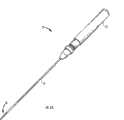
图1A是处于初始、未展开状态的闭合装置的一个示例性实施例的透视图;Figure 1A is a perspective view of an exemplary embodiment of a closure device in an initial, undeployed state;
图1B是图1A中的闭合装置在展开之前的剖视图;Figure 1B is a cross-sectional view of the closure device of Figure 1A prior to deployment;
图1C是图1A中的闭合装置在远端翼张开后的端视图;Figure 1C is an end view of the closure device of Figure 1A after the distal wings have been deployed;
图1D是图1A中的闭合装置在近端翼张开后的端视图;FIG. 1D is an end view of the closure device of FIG. 1A with the proximal wings expanded;
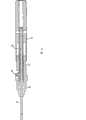
图2A是用于展开闭合装置的驱动器的一个示例性实施例的透视图,示出图1A中闭合装置连接在该驱动器上;Figure 2A is a perspective view of an exemplary embodiment of a driver for deploying a closure device, showing the closure device of Figure 1A attached to the driver;
图2B是图1A中的闭合装置和图2A中的驱动器的内轴的剖视图;Figure 2B is a cross-sectional view of the closure device in Figure 1A and the inner shaft of the driver in Figure 2A;
图2C是图1A中的闭合装置的另一个实施例和图2A中的驱动器的内轴的剖视图;Figure 2C is a cross-sectional view of another embodiment of the closure device in Figure 1A and the inner shaft of the driver in Figure 2A;
图2D是图2A中的驱动器的成形器管的一部分的透视图,其连接至图1A中的闭合装置;Figure 2D is a perspective view of a portion of the shaper tube of the driver in Figure 2A connected to the closure device in Figure 1A;
图2E是与图2A中的驱动器一起使用的成形器管的另一实施例的剖面图;Figure 2E is a cross-sectional view of another embodiment of a shaper tube for use with the driver in Figure 2A;
图2F是与图2A中的驱动器一起使用的成形器管的又一实施例的剖面图;Figure 2F is a cross-sectional view of yet another embodiment of a shaper tube for use with the driver in Figure 2A;
连续的步骤用于展开闭合装置来闭合动脉壁的穿刺孔;Successive steps are used to deploy the closure device to close the puncture hole in the arterial wall;
图3A是图1A中的闭合装置和图2A中的驱动器的一部分的剖面图,示出了闭合装置展开来闭合动脉壁上的穿刺伤口;3A is a cross-sectional view of a portion of the closure device in FIG. 1A and the driver in FIG. 2A showing deployment of the closure device to close a puncture wound on an artery wall;
图3B是驱动器的成形器管缩回后图3A中的闭合装置和驱动器的一部分的剖面图;Figure 3B is a cross-sectional view of a portion of the closure device and driver of Figure 3A after the former tube of the driver is retracted;
图3C是驱动器的内轴分离后图3B中的闭合装置和驱动器的一部分的剖面图;Figure 3C is a cross-sectional view of a portion of the closure device and driver of Figure 3B with the inner shaft of the driver separated;
图4A是图2A中的驱动器的手柄部分的剖面图;Figure 4A is a cross-sectional view of the handle portion of the driver in Figure 2A;
图4B是图4A的驱动器的近端部在初始、开始位置的透视图;4B is a perspective view of the proximal portion of the driver of FIG. 4A in an initial, starting position;
图4C是闭合装置的远端翼展开后图4B所示的驱动器的近端部的透视图;4C is a perspective view of the proximal portion of the driver shown in FIG. 4B with the distal wings of the closure device deployed;
图4D是近端翼展开后图4C所示的驱动器的近端部的透视图;Figure 4D is a perspective view of the proximal portion of the driver shown in Figure 4C after the proximal wings have been deployed;
图5是放置在股动脉中的导引鞘的一个实施例的局部剖面图;Figure 5 is a partial cross-sectional view of one embodiment of an introducer sheath placed in the femoral artery;
图6是图5中的导引鞘带有穿过该导引鞘放置的闭合装置和驱动器的局部剖面图;Figure 6 is a partial cross-sectional view of the introducer sheath of Figure 5 with the closure device and driver placed through the introducer sheath;
图7是导引鞘、闭合装置和图6中带有放置在股动脉内的闭合装置的驱动器的局部剖面图;Figure 7 is a partial cross-sectional view of the introducer sheath, closure device, and driver of Figure 6 with the closure device placed in the femoral artery;
图8A是远端翼展开后图7中的闭合装置的局部剖面图;Figure 8A is a partial cross-sectional view of the closure device of Figure 7 after the distal wings have been deployed;
图8B是远端翼在展开后图7中的驱动器的透视图;Figure 8B is a perspective view of the driver of Figure 7 after the distal wings have been deployed;
图9是图8A中的闭合装置缩回来结合穿刺孔时的局部剖面图;Figure 9 is a partial cross-sectional view of the closing device in Figure 8A retracted to engage the puncture hole;
图10A是图9中的闭合装置在近端翼展开来接合近端翼和远端翼之间的穿刺孔时的局部剖面图;和10A is a partial cross-sectional view of the closure device of FIG. 9 with the proximal wings deployed to engage the puncture hole between the proximal and distal wings; and
图10B是闭合装置的近端翼完全展开后图8B中的驱动器的透视图。Figure 10B is a perspective view of the driver of Figure 8B with the proximal wings of the closure device fully deployed.
具体实施方式Detailed ways
现在将描述一些示例性的实施例,以对本文中公开的结构、功能、制造原理以及装置的用途和方法有一个总体了解。附图中示出了这些实施例的一个或多个实例。本领域的普通技术人员应当理解在本文中具体描述和附图中示出的装置和方法是非限制性的示例性实施例,并且本发明的范围仅由后续的权利要求书来限定。通过一个示例性实施例描述和示出的特征可以与其它实施例中的特征相结合。这样的修改和变化将包含在本发明的范围内。Some exemplary embodiments will now be described to provide an overview of the structure, function, principles of manufacture, and uses and methods of the devices disclosed herein. One or more examples of these embodiments are illustrated in the accompanying drawings. Those of ordinary skill in the art should understand that the devices and methods specifically described herein and illustrated in the accompanying drawings are non-limiting exemplary embodiments and that the scope of the present invention is defined only by the appended claims. Features described and illustrated by one exemplary embodiment may be combined with features of other embodiments. Such modifications and changes are intended to be included within the scope of the present invention.
本发明提供了用于闭合组织中的穿刺伤口的方法和装置。通常,闭合装置可以是以适合放置在穿刺孔中的细长体的形式,该细长体包括近端部和远端部,所述近端部和远端部配置成能径向张开来接合位于其间的组织,从而闭合穿刺孔。图1A示出了这种闭合装置10的一个示例性的实施例。该装置10是以初始的、未展开的结构示出,并且如图所示装置10是以通常为细长管状体12的形式,该管状体具有闭合或密封的远端10b和敞开的近端10a。管状体12可以由多种材料制成。在一个示例性的实施例中,闭合装置由可经受塑性变形(例如,可忽略弹性的元件的变形)的可变形材料构成。作为非限定性的例子,示例性的材料包括各种生物相容性材料和/或生物可吸收材料,包括,如钛(和钛合金)、镁合金、不锈钢、聚合材料(合成的和/或天然的)、陶瓷等。能够正常透过射线的材料例如镁合金,可以被强化并通过加入X射线可见材料例如氧化铁颗粒、不锈钢、钛、钽、铂或其它适合的等效物质使X射线可见。细长管状体12也可以采用多种工艺制成。例如,该管状体12可以由一段管形材料制成或者由片状坯料制成。最终的管状形状的展开面可以被冲压且折弯成型。可以采用多种连接方法如熔焊、软焊等来接合各种接缝。The present invention provides methods and devices for closing puncture wounds in tissue. Typically, the closure device may be in the form of an elongated body adapted to be placed in the puncture hole, the elongated body comprising a proximal portion and a distal portion configured to expand radially to engage a The intervening tissue closes the puncture hole. An exemplary embodiment of such a
如上所述,装置10可包括一个或多个部分,所述部分能张开以接合其间的组织从而闭合穿刺创口。在图1A所示的实施例中,所述装置包括近端部和远端部12a、12b,配置成能张开以接合它们之间的组织。虽然可以使用多种工艺使近端部和远端部12a、12b能够张开,但在下面将作讨论的一个示例性的实施例中,近端部和远端部12a、12b各包括在其中形成的多个狭缝14a、14b,狭缝配置成使细长管状体12位于多个狭缝14a、14b之间的部分能径向张开。位于近端部和远端部12a、12b之间的管状体12的中部13可不张开并且长度可以变化。中部13配置成能放置在穿刺孔中,因此该中部的长度与组织壁的厚度相对应。另外,中部13还可以配置成向外张开。细长管状体12在中部13处的壁上设有孔和狭槽形式的开口。As noted above,
近端部和远端部12a、12b上的狭缝14a、14b可以在任意方向上延伸,并且各部12a、12b可包括多个狭缝。优选狭缝14a、14b配置成当管状体12轴向压缩并且优选在旋转时,使得在狭缝之间的细长管状体12的某些部分将向外离开管状体12的中心轴线A张开。因此,在近端部和远端部12a、12b上将各形成一个或多个翼以接合位于其间的组织。在一个示例性的实施例中,如图1A所示,近端部和远端部12a、12b中的狭缝14a、14b是弧曲的,且在垂直于细长管状体12的中心轴线A的方向上延伸,使得这些狭缝至少部分地绕细长管状体12延伸。最好是,在近端部12a上的狭缝14a在第一方向上绕着细长管状体12的圆周延伸,而在远端部12b上的狭缝14b在相反的第二方向上绕细长管状体12的圆周延伸。这样的结构使管状体12能在第一方向上旋转以仅使近端部和远端部12a、12b之一径向张开,然后在第二方向上旋转以使所述近端部和远端部12a、12b中的另一端部径向张开。本领域的技术人员将会理解狭缝14a、14b可以具有多种其它的形状和尺寸,且它们可以在多个方向上延伸,如螺旋状或平行于管状体的中心轴线A。狭缝14a、14b还可包括从主狭缝14a、14b的各末端延伸出来的附加的弯曲狭缝,以保证在展开后,所述翼的端部轮廓均匀地接在闭合装置10的主管状体12上。这有助于保证流体密封性。这种弧曲的端部狭缝也可以缩小狭缝之间的管状部分的宽度,因此在这一点上促使翼向外弯曲。The slits 14a, 14b on the proximal and distal sections 12a, 12b may extend in any direction, and each section 12a, 12b may comprise a plurality of slits. Preferably the slits 14a, 14b are configured such that certain portions of the elongated tubular body 12 between the slits will flare outwardly away from the central axis A of the tubular body 12 when the tubular body 12 is axially compressed and preferably rotated. . Accordingly, one or more wings will be formed on each of the proximal and distal portions 12a, 12b to engage tissue located therebetween. In an exemplary embodiment, as shown in FIG. 1A , the slits 14a, 14b in the proximal and distal portions 12a, 12b are curved, and are perpendicular to the central axis A of the elongated tubular body 12. , such that the slits extend at least partially around the elongated tubular body 12. Preferably, the slit 14a on the proximal portion 12a extends around the circumference of the elongated tubular body 12 in a first direction, while the slit 14b on the distal portion 12b extends around the circumference of the elongated tubular body 12 in an opposite second direction. The circumference of the elongated tubular body 12 extends. Such a structure enables the tubular body 12 to be rotated in a first direction to radially expand only one of the proximal and distal portions 12a, 12b, and then rotated in a second direction to cause said proximal and distal portions to expand radially. The other of the end portions 12a, 12b is radially flared. Those skilled in the art will appreciate that the slits 14a, 14b may have various other shapes and sizes, and that they may extend in multiple directions, such as helically or parallel to the central axis A of the tubular body. The slits 14a, 14b may also include additional curved slits extending from each end of the main slit 14a, 14b to ensure that after deployment, the end profiles of the wings evenly abut the main tube shape of the
图1B至1D示出了闭合装置10的远端视图,分别为闭合装置10展开前、部分展开和完全展开之后的结构。在展开前的结构中,如图1B所示,细长管状体12的直径配置成适合放置在血管的穿刺孔内,并且还优选配置成适合放置在用于引导装置10到穿刺点的导管鞘中,这将会在下文中更详细地进行描述。图1C示出了远端部12b径向张开形成远端翼16b,并且图1D示出了近端部12a径向张开形成近端翼16a。翼16a、16b由位于狭缝14a、14b之间的材料部分形成,当细长管状体12a被压缩并且最好是旋转时,所述材料部分向外发生变形。在图中示出的实施例中,狭缝14a、14b配置成使近端部和远端部12a、12b各包括三个翼16a、16b,然而近端部和远端部12a、12b可以包括任意个翼16a、16b。翼16a、16b的尺寸和形状也可以依狭缝14a、14b的位置和长度而变化。在一个示例性的实施例中,翼16a、16b的尺寸和形状被最大化以使翼16a、16b和穿刺孔周围的组织之间的接触面积最大,其中闭合装置10在该穿刺孔内展开。如图1C和1D所示,翼16a、16b大体上呈卵形并且具有大致是平状的结构,使得所述翼16a、16b能基本上彼此平行延伸。如图1D所示,远端和近端翼16a、16b也可以设计成彼此错开来进一步最大化穿刺伤口周围的接触面积。近端翼和远端翼16a、16b也可以优选配置成彼此分开一定的距离。中部13的长度取决于翼16a、16b之间的距离。Figures 1B to 1D show distal views of the
闭合装置10的翼16a、16b和/或其他的部分也可选择性地包括延伸部或突起,配置成能刺向所接合的组织。例如,每个翼16a、16b可包括一个或多个在其上形成的穿向组织的突起。所述延伸部或突起可以更好地帮助闭合装置固定在穿刺位置,且它们也可以被用于帮助穿刺孔的闭合。在展开期间,在下文中将会进行更详细地描述,延伸部或突起可以刺向穿刺伤口周围的组织,并且在翼16a、16b旋转时将会以螺旋运动扭曲这些组织,以使组织压缩穿刺伤口周围部分并封闭穿刺孔。
如上所述,可以通过压缩并且优选旋转闭合装置10来形成闭合装置10上的翼16a、16b。可使用多种技术来展开和驱动闭合装置10,在一个示例性的实施例中,闭合装置10可移动地与驱动器相结合,驱动器适合于施加轴向力和旋转力给细长管状体12以使该细长管状体12向外张开。图2A示出了用于展开闭合装置10的驱动器20的一个示例性的实施例。通常,驱动器20包括手柄22形式的近端部,以及从手柄22向远侧延伸的细长轴,该细长轴具有可移去地和闭合装置10相结合的远端。细长轴优选包括外轴24,以下称为成形器24,成形器24能有效施加轴向力和/或旋转力给闭合装置10,细长轴还包括与闭合装置10相配合的内轴26(如图2B和2C所示),当轴向力和/或旋转力施加给闭合装置10以使闭合装置10变形时,内轴26能有效地保持闭合装置10的一部分在固定的位置,这将会在下文中更详细地进行描述。驱动器20也可以包括附连在成形器24远端上的套筒(未示出)。套筒有助于防止闭合装置10与驱动器20分离。As mentioned above, the
内轴26可在不同的位置和采用不同的工艺连接到闭合装置10。在一个示例性的实施例中,内轴26可移动地与闭合装置10相连接,且更优选内轴26易碎地连接到闭合装置10,以在装置展开后,使至少内轴26的一部分可以从闭合装置10脱离和分开。图2B示出了内轴26的一个示例性的实施例,该内轴与闭合装置10在易碎部28处相连接。如图所示,内轴26延伸穿过闭合装置10,且附连在闭合装置10的封闭远端10b上。可使用粘合剂或其他任何配合方法使内轴26的远端附连在闭合装置10的远端10b上。轴26的易碎部28的配置成将力施加在该易碎部上时可以断开。易碎部28可在内轴26上的任意位置形成,例如,内轴26的最末端可以配置为从闭合装置10的远端10b上脱离。另外,如图2B所示,易碎部28可以位于与闭合装置10的远端10b隔开一定距离的位置,使得内轴26的一部分将保持附连在闭合装置10上,并且内轴26的剩余部分能与闭合装置10分离。易碎部28可以采用本领域公知的多种技术制成。例如,内轴26可以包括薄或易破碎的区域。这可通过减少那个区域的材料的量实现,或者通过划痕,或者另外通过移去用于形成内轴26的一部分材料来实现。在使用时,可以通过在内轴26上施加力如旋转力或轴向力使易碎部28破碎。在其他的实施例中,内轴26可使用螺纹连接附连到闭合装置10上。在使用过程中,内轴26可相对闭合装置10旋转以将内轴26从闭合装置10上旋下。一旦脱离,内轴26将从患者体内移走,在穿刺位置留下闭合装置10。本领域的技术人员能够理解可以使用多种配合手段,包括例如过盈配合、机械联锁等。The
在另一个实施例中,如图2C所示,内轴26’可以包括直径减小的区域27’形成易碎部28’的远端。当闭合装置10’完全展开时,直径减小的区域27’优选配置为与闭合装置10’的中部13’准直。如图2C进一步所示,闭合装置10’可包括一个或多个孔或开口11’,所述孔或开口位于装置10’的中部13’的侧壁上。在使用时,直径减小的区域27’将被放置在与孔11’邻近的穿刺伤口内中。这使得在闭合装置10’被吸收过程中和吸收之后血液能通过孔11’进入以使组织开始生长。In another embodiment, as shown in Figure 2C, the inner shaft 26' may include a reduced diameter region 27' forming the distal end of the frangible portion 28'. The reduced diameter region 27' is preferably configured to align with the middle portion 13' of the closure device 10' when the closure device 10' is fully deployed. As further shown in Figure 2C, the closure device 10' may include one or more holes or openings 11' in the side walls of the middle portion 13' of the device 10'. In use, the reduced diameter region 27' will be placed in the puncture wound adjacent to the hole 11'. This allows blood to enter through the pores 11' to initiate tissue growth during and after the closure device 10' is absorbed.
如上所述,驱动器20也可包括外轴或成形器24,该外轴或成形器绕内轴26布置并且能将轴向力和/或旋转力有效施加到闭合装置10以展开该闭合装置10。成形器24可具有多种结构,但优选适合与闭合装置10的近端10a相连接。虽然可采用多种技术将成形器24连接到闭合装置10,但图2D只示出了一个示例性的方案。如图所示,成形器24包括一个或多个突起24a,该突起24a延伸到在闭合装置10的近端上形成的一个或多个互补凹槽或切口15中。As noted above, the
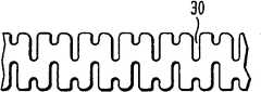
在临床使用中,成形器24也可以配置为能提供最大的柔性。而成形器24可仅由柔性材料制成,在另一个实施例中,成形器24可以包括一个或多个在该成形器上的形成的柔性区域。图2E和2F示出了柔性区域的示例性实施例。如图2E所示的实施例中,该管包括断续的槽形图案30。如图2F所示的实施例中,所述管包括穿透管壁的螺旋狭缝或断续的螺旋狭缝32。这种结构为成形器提供了沿整个长度的柔性,但还可以保证施加在成形器一端的轴向力和/或旋转力将会沿成形器的长度传送到另一端。The shaper 24 can also be configured to provide maximum flexibility in clinical use. While the
图3A至3B示出了与闭合装置10一起使用的成形器24的远端部和驱动器20的内轴26,该闭合装置10放置在穿刺伤口中且完全展开以闭合伤口。在图3A中,成形器24上的突起24a安置于在闭合装置10的近端上形成的相应的切口15中,使得成形器24与闭合装置10相配合。如图所示,成形器24因此可以相对于内轴26旋转,从而旋转闭合装置10的近端部和远端部以形成近端翼和远端翼来接合其间的组织。在闭合装置10展开后,驱动器必须从患者体内分离和移去。图3B示出了成形器24相对于闭合装置10缩回以露出位于内轴26上形成的易碎部28。如图3C所示,当露出易碎部28后,可以给内轴26施加一个力以使该易碎部28断开,从而将轴26的近端部和轴的远端部分开,轴的远端部仍和闭合装置10保持连接。3A-3B illustrate the distal end of the
为了使成形器管24相对于内轴26进行有效的旋转,驱动器20的手柄22可选择地包括装在该手柄上的驱动机构。在一个示例性的实施例中,如图4A至4D所示,手柄22包括可旋转地围绕其布置的外外环36并具有在该手柄上形成的导槽38。外环36可与成形器24的近端部相连接使得该外环36的旋转能有效旋转成形器24。内轴26的近端也可以包括附连在内轴26上的内环37,内环37还包括其上形成的或者从其上延伸出的销40。销40延伸穿过导槽38且定位在该导槽内。因为销40的被定位的位置取决于内轴26被固定的位置,所以外环36的运动和因此产生的成形器24的运动,均取决于可以相对于固定的销40移动的导槽38的结构。因此,导槽38可用于控制施加到与成形器24的远端相连接的闭合装置10上轴向力和旋转力。In order to effectively rotate the
如图4B至4D所示,导槽38可具有一种使外环36在第一方向例如逆时针方向上旋转的结构,以展开闭合装置的远端翼。特别是当外环36沿逆时针旋转时,成形器管24将以逆时针方向旋转,从而旋转闭合装置10的近端来张开该闭合装置的远端翼。如上所述,因为近端部和远端部的狭缝优选在相反的方向上延伸,闭合装置在第一方向上的旋转将仅展开远端翼。一旦外环36被完全旋转,导槽38可以允许外环36的远端移动,而定位销40始终保持在一个固定的位置,从而使外环36能向远端推进。因此,成形器管24会将压缩力施加在闭合装置上,从而使远端翼压扁形成一种大体上呈平状的结构。As shown in Figures 4B to 4D, the channel 38 may have a configuration to rotate the
然后,导槽38可以允许外环36在相反的方向如顺时针方向上旋转,以使成形器管24能顺时针旋转。当成形器管24顺时针旋转时,近端翼将展开。一旦外环36被完全旋转,导槽38可以允许外环36的远端运动,从而使外环36向远端推进。因此,成形器管24会将压缩力施加在闭合装置上,从而使近端翼压扁形成一种大体上呈平状的结构。导槽38可以包括允许外环36向近端移动的轨道部分,如图4C所示,从而允许成形器24可以相对于闭合装置10缩回,从而露出内轴上的易碎部。The guide slots 38 may then allow the
本领域的技术人员可以理解导槽38可以具有多种其它的结构。例如,取代旋转并且然后向远端运动的方式,导槽38也可以以一定的角度绕着手柄22延伸以使旋转力和压缩力可以同时施加在闭合装置上。本领域的技术人员可以理解可用多种其它的技术来驱动成形器24展开闭合装置。Those skilled in the art can understand that the guide groove 38 can have various other structures. For example, instead of rotating and then moving distally, channel 38 could also extend at an angle around handle 22 so that rotational and compressive forces can be applied to the closure device simultaneously. Those skilled in the art will understand that a variety of other techniques can be used to actuate the former 24 to deploy the closure device.
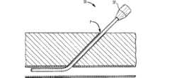
本发明还提供了用于闭合穿刺伤口的示例性方法。虽然可用多种装置来实现所述的方法,在图5至9只示出了使用图1A中的闭合装置10和图2A中的驱动器20来闭合穿刺伤口的示例性方法。在治疗和诊断过程中,导引鞘通常放置在血管例如股动脉中,以帮助将导管输送到血管系统中。如图5所示,导引鞘50通常包括位于其远端上带有阀的插套52以阻止血液泄露。且阀可以配置成能帮助元件进入鞘50,并向前进入穿刺伤口或者脉管系统中。在输送闭合装置之前,导引鞘50被完全向前推进穿刺伤口P中直到插套52与皮肤接触。然后,如图6所示,驱动器20的成形器24被推进穿过导引鞘插套52并且向前穿过鞘50。在一个示例性的实施例中,成形器管24可以包括一个在其上形成的标记,标记可以与导引鞘50上的插套52的最近端对齐,以将闭合装置10保留在导引鞘50中,从而防止血管壁受到损伤。如图7所示,当驱动器位置固定后,导引鞘50可以沿着成形器24被拉回直到该导引鞘接触到驱动器20上的手柄22。现在闭合装置10暴露在血管腔中并准备展开。The invention also provides exemplary methods for closing puncture wounds. While a variety of devices can be used to implement the described methods, only an exemplary method of closing a puncture wound using the
另外,可以在闭合装置10的壁上或成形器管24的远端的壁上布置侧孔。该孔可与通向驱动器的手柄22的管状通道相通。当驱动器20被推进穿过鞘50时,侧孔将不会与血流接触。一旦闭合装置10和/或成形器24的远端脱离鞘50进入股动脉,血液将会进入侧孔且上涨穿过通道从驱动器手柄22流出。这将给使用者发出信号,即闭合装置10现在已经在血管腔中,不需要再推进且装置10准备展开。Additionally, side holes may be disposed on the wall of the
在其它实施例中,装置10可以沿导丝送到动脉内腔中。从患者体内延伸出来的导丝的近端可以被插入闭合装置10远端的开口。它可以延伸穿过驱动器20的轴和手柄22,或者在其它实施例中,它可以从位于闭合装置10上的或成形器管24的远端上的侧孔退出。In other embodiments,
一旦放置好的闭合装置10要被展开,驱动器20的手柄22上的外环36可以在第一方向例如图8B所示的逆时针方向上旋转,以使闭合装置10的远端部张开离开中心轴。可以同时或随后将一个压缩力施加在闭合装置10上以使闭合装置10的已张开部分压扁,并因此形成远端翼16b,如图8A所示。Once the placed
在远端翼16b张开后,驱动器20和导引鞘50可以从病人体内收回直到感觉到张力,这表明远端翼16b已经在穿刺位置的内表面上的正确位置,如图9所示。近端翼现在可以展开以完成穿刺孔P的闭合。如图10B所示,这可以通过在相反的方向例如顺时针方向上旋转驱动器的外环36实现。而这使成形器管24顺时针方向旋转闭合装置10的近端,使闭合装置10的近端部向外张开。成形器管24可以同时或随后向远端推进,使闭合装置10已张开部分压扁并形成近端翼16a,如图10A所示。因此,近端翼和远端翼16a、16b接合位于其间的穿刺孔P周围的组织。闭合装置10现在完全地展开并且穿刺孔P被封闭。如前所述,驱动器20可以被移去。After the
本领域的技术人员基于上述实施例将会理解本发明的其它特征和优点。因此,除了后面的权利要求书所指明的,本发明不受具体图示的和描述的内容限定。本文所引用的所有出版物和参考文献整体纳入本文作为参考。Other features and advantages of the present invention will be understood by those skilled in the art based on the above-described embodiments. Accordingly, the invention is not to be limited by what has been particularly shown and described, except as indicated by the appended claims. All publications and references cited herein are incorporated by reference in their entirety.
Claims (40)
Translated fromChineseApplications Claiming Priority (3)
| Application Number | Priority Date | Filing Date | Title |
|---|---|---|---|
| US11/307,372 | 2006-02-03 | ||
| US11/307,372US7625392B2 (en) | 2006-02-03 | 2006-02-03 | Wound closure devices and methods |
| PCT/EP2007/000927WO2007088069A1 (en) | 2006-02-03 | 2007-02-02 | Wound closure devices |
Related Child Applications (1)
| Application Number | Title | Priority Date | Filing Date |
|---|---|---|---|
| CN201210139455.2ADivisionCN102824199B (en) | 2006-02-03 | 2007-02-02 | Wound closure device |
Publications (2)
| Publication Number | Publication Date |
|---|---|
| CN101410063A CN101410063A (en) | 2009-04-15 |
| CN101410063Btrue CN101410063B (en) | 2012-07-04 |
Family
ID=37888208
Family Applications (2)
| Application Number | Title | Priority Date | Filing Date |
|---|---|---|---|
| CN2007800044826AActiveCN101410063B (en) | 2006-02-03 | 2007-02-02 | wound closure device |
| CN201210139455.2AActiveCN102824199B (en) | 2006-02-03 | 2007-02-02 | Wound closure device |
Family Applications After (1)
| Application Number | Title | Priority Date | Filing Date |
|---|---|---|---|
| CN201210139455.2AActiveCN102824199B (en) | 2006-02-03 | 2007-02-02 | Wound closure device |
Country Status (14)
| Country | Link |
|---|---|
| US (5) | US7625392B2 (en) |
| EP (2) | EP2275038B1 (en) |
| JP (1) | JP5089609B2 (en) |
| KR (1) | KR20080110741A (en) |
| CN (2) | CN101410063B (en) |
| AT (1) | ATE482652T1 (en) |
| AU (1) | AU2007211551B2 (en) |
| BR (1) | BRPI0707447B8 (en) |
| CA (1) | CA2640480C (en) |
| DE (1) | DE602007009486D1 (en) |
| ES (2) | ES2353260T3 (en) |
| MX (1) | MX2008009695A (en) |
| WO (1) | WO2007088069A1 (en) |
| ZA (1) | ZA200810282B (en) |
Families Citing this family (118)
| Publication number | Priority date | Publication date | Assignee | Title |
|---|---|---|---|---|
| US7662161B2 (en) | 1999-09-13 | 2010-02-16 | Rex Medical, L.P | Vascular hole closure device |
| US9579091B2 (en) | 2000-01-05 | 2017-02-28 | Integrated Vascular Systems, Inc. | Closure system and methods of use |
| US6391048B1 (en) | 2000-01-05 | 2002-05-21 | Integrated Vascular Systems, Inc. | Integrated vascular device with puncture site closure component and sealant and methods of use |
| US8758400B2 (en) | 2000-01-05 | 2014-06-24 | Integrated Vascular Systems, Inc. | Closure system and methods of use |
| DE60144328D1 (en) | 2000-09-08 | 2011-05-12 | Abbott Vascular Inc | Surgical clamp |
| US6626918B1 (en) | 2000-10-06 | 2003-09-30 | Medical Technology Group | Apparatus and methods for positioning a vascular sheath |
| US7905900B2 (en) | 2003-01-30 | 2011-03-15 | Integrated Vascular Systems, Inc. | Clip applier and methods of use |
| US8690910B2 (en) | 2000-12-07 | 2014-04-08 | Integrated Vascular Systems, Inc. | Closure device and methods for making and using them |
| US6623510B2 (en) | 2000-12-07 | 2003-09-23 | Integrated Vascular Systems, Inc. | Closure device and methods for making and using them |
| US6695867B2 (en) | 2002-02-21 | 2004-02-24 | Integrated Vascular Systems, Inc. | Plunger apparatus and methods for delivering a closure device |
| IES20030424A2 (en) | 2002-06-04 | 2003-12-10 | Robert Stevenson | Blood vessel closure clip and delivery device |
| US8202293B2 (en) | 2003-01-30 | 2012-06-19 | Integrated Vascular Systems, Inc. | Clip applier and methods of use |
| US8398656B2 (en) | 2003-01-30 | 2013-03-19 | Integrated Vascular Systems, Inc. | Clip applier and methods of use |
| US8905937B2 (en) | 2009-02-26 | 2014-12-09 | Integrated Vascular Systems, Inc. | Methods and apparatus for locating a surface of a body lumen |
| US9861346B2 (en) | 2003-07-14 | 2018-01-09 | W. L. Gore & Associates, Inc. | Patent foramen ovale (PFO) closure device with linearly elongating petals |
| US8480706B2 (en) | 2003-07-14 | 2013-07-09 | W.L. Gore & Associates, Inc. | Tubular patent foramen ovale (PFO) closure device with catch system |
| EP2481356B1 (en) | 2003-07-14 | 2013-09-11 | W.L. Gore & Associates, Inc. | Tubular patent foramen ovale (PFO) closure device with catch system |
| US8926633B2 (en) | 2005-06-24 | 2015-01-06 | Abbott Laboratories | Apparatus and method for delivering a closure element |
| US8313497B2 (en) | 2005-07-01 | 2012-11-20 | Abbott Laboratories | Clip applier and methods of use |
| US8920442B2 (en) | 2005-08-24 | 2014-12-30 | Abbott Vascular Inc. | Vascular opening edge eversion methods and apparatuses |
| US9456811B2 (en) | 2005-08-24 | 2016-10-04 | Abbott Vascular Inc. | Vascular closure methods and apparatuses |
| US7625392B2 (en)* | 2006-02-03 | 2009-12-01 | James Coleman | Wound closure devices and methods |
| US8556930B2 (en) | 2006-06-28 | 2013-10-15 | Abbott Laboratories | Vessel closure device |
| US20080109033A1 (en)* | 2006-10-31 | 2008-05-08 | Texas Heart Institute | Method and device for prevention of pneumothorax during vascular access |
| US10413284B2 (en) | 2006-11-07 | 2019-09-17 | Corvia Medical, Inc. | Atrial pressure regulation with control, sensing, monitoring and therapy delivery |
| US9232997B2 (en) | 2006-11-07 | 2016-01-12 | Corvia Medical, Inc. | Devices and methods for retrievable intra-atrial implants |
| US20110257723A1 (en) | 2006-11-07 | 2011-10-20 | Dc Devices, Inc. | Devices and methods for coronary sinus pressure relief |
| EP2097012A4 (en) | 2006-11-07 | 2012-08-15 | David Stephen Celermajer | Devices and methods for the treatment of heart failure |
| WO2008115922A1 (en) | 2007-03-19 | 2008-09-25 | Michael Brenzel | Methods and apparatus for occlusion of body lumens |
| US9005242B2 (en) | 2007-04-05 | 2015-04-14 | W.L. Gore & Associates, Inc. | Septal closure device with centering mechanism |
| US9259233B2 (en) | 2007-04-06 | 2016-02-16 | Hologic, Inc. | Method and device for distending a gynecological cavity |
| EP2178445B1 (en)* | 2007-07-17 | 2012-10-03 | Cook Medical Technologies LLC | Rivet introduction system |
| JP5426553B2 (en)* | 2007-09-12 | 2014-02-26 | トランスルミナル テクノロジーズ リミテッド ライアビリティー カンパニー | Closure device, placement device, and method of placing a closure device |
| US9301761B2 (en) | 2007-10-22 | 2016-04-05 | James E. Coleman | Anastomosis devices and methods |
| US8893947B2 (en) | 2007-12-17 | 2014-11-25 | Abbott Laboratories | Clip applier and methods of use |
| US8070772B2 (en) | 2008-02-15 | 2011-12-06 | Rex Medical, L.P. | Vascular hole closure device |
| US8920463B2 (en) | 2008-02-15 | 2014-12-30 | Rex Medical, L.P. | Vascular hole closure device |
| US9226738B2 (en) | 2008-02-15 | 2016-01-05 | Rex Medical, L.P. | Vascular hole closure delivery device |
| US8491629B2 (en) | 2008-02-15 | 2013-07-23 | Rex Medical | Vascular hole closure delivery device |
| US20110029013A1 (en) | 2008-02-15 | 2011-02-03 | Mcguckin James F | Vascular Hole Closure Device |
| US8920462B2 (en) | 2008-02-15 | 2014-12-30 | Rex Medical, L.P. | Vascular hole closure device |
| US20130165967A1 (en) | 2008-03-07 | 2013-06-27 | W.L. Gore & Associates, Inc. | Heart occlusion devices |
| US20090270911A1 (en)* | 2008-04-24 | 2009-10-29 | Shipp John I | Vessel Sealing Device and Method of Using Same |
| US9282965B2 (en) | 2008-05-16 | 2016-03-15 | Abbott Laboratories | Apparatus and methods for engaging tissue |
| US9943302B2 (en) | 2008-08-12 | 2018-04-17 | Covidien Lp | Medical device for wound closure and method of use |
| US9271706B2 (en) | 2008-08-12 | 2016-03-01 | Covidien Lp | Medical device for wound closure and method of use |
| EP2328485B1 (en)* | 2008-08-18 | 2012-06-06 | Cook Medical Technologies LLC | Device for closure of vessel access site |
| US8398676B2 (en)* | 2008-10-30 | 2013-03-19 | Abbott Vascular Inc. | Closure device |
| US8197498B2 (en)* | 2008-11-06 | 2012-06-12 | Trinitas Ventures Ltd. | Gastric bypass devices and procedures |
| US8858594B2 (en) | 2008-12-22 | 2014-10-14 | Abbott Laboratories | Curved closure device |
| US9089311B2 (en) | 2009-01-09 | 2015-07-28 | Abbott Vascular Inc. | Vessel closure devices and methods |
| US9414820B2 (en) | 2009-01-09 | 2016-08-16 | Abbott Vascular Inc. | Closure devices, systems, and methods |
| US9173644B2 (en) | 2009-01-09 | 2015-11-03 | Abbott Vascular Inc. | Closure devices, systems, and methods |
| US20100179589A1 (en) | 2009-01-09 | 2010-07-15 | Abbott Vascular Inc. | Rapidly eroding anchor |
| US9486191B2 (en) | 2009-01-09 | 2016-11-08 | Abbott Vascular, Inc. | Closure devices |
| US20100185234A1 (en) | 2009-01-16 | 2010-07-22 | Abbott Vascular Inc. | Closure devices, systems, and methods |
| US20120029556A1 (en) | 2009-06-22 | 2012-02-02 | Masters Steven J | Sealing device and delivery system |
| US9636094B2 (en) | 2009-06-22 | 2017-05-02 | W. L. Gore & Associates, Inc. | Sealing device and delivery system |
| US20110054492A1 (en) | 2009-08-26 | 2011-03-03 | Abbott Laboratories | Medical device for repairing a fistula |
| US9757107B2 (en) | 2009-09-04 | 2017-09-12 | Corvia Medical, Inc. | Methods and devices for intra-atrial shunts having adjustable sizes |
| JP5744893B2 (en)* | 2009-11-09 | 2015-07-08 | アントラージュ メディカル テクノロジーズ,インコーポレイテッドEntourage Medical Technologies,Inc. | Systems that provide access and closure to the organization |
| US8753358B2 (en)* | 2010-01-20 | 2014-06-17 | Douglas Wesley Cook | Dial fan hernia mesh system |
| WO2011094521A2 (en) | 2010-01-29 | 2011-08-04 | Dc Devices, Inc. | Devices and methods for reducing venous pressure |
| EP2528646A4 (en) | 2010-01-29 | 2017-06-28 | DC Devices, Inc. | Devices and systems for treating heart failure |
| US8506593B2 (en) | 2010-04-11 | 2013-08-13 | Lap IP, Inc | Implantable biodegradable wound closure device and method |
| US20120283758A1 (en)* | 2011-01-11 | 2012-11-08 | Arnold Miller | Method and apparatus for treating varicose veins |
| US10398445B2 (en)* | 2011-01-11 | 2019-09-03 | Amsel Medical Corporation | Method and apparatus for clamping tissue layers and occluding tubular body structures |
| WO2012109557A2 (en) | 2011-02-10 | 2012-08-16 | Dc Devices, Inc. | Apparatus and methods to create and maintain an intra-atrial pressure relief opening |
| US12303119B2 (en) | 2011-02-10 | 2025-05-20 | Corvia Medical, Inc. | Apparatus and methods to create and maintain an intra-atrial pressure relief opening |
| US9149276B2 (en) | 2011-03-21 | 2015-10-06 | Abbott Cardiovascular Systems, Inc. | Clip and deployment apparatus for tissue closure |
| US9332981B2 (en) | 2011-05-19 | 2016-05-10 | Abbott Cardiovascular Systems, Inc. | Closure devices and methods |
| US9770232B2 (en) | 2011-08-12 | 2017-09-26 | W. L. Gore & Associates, Inc. | Heart occlusion devices |
| GB201119375D0 (en)* | 2011-11-10 | 2011-12-21 | Merburn Ltd | Financial transaction processing system and method |
| US9332976B2 (en) | 2011-11-30 | 2016-05-10 | Abbott Cardiovascular Systems, Inc. | Tissue closure device |
| US9247930B2 (en) | 2011-12-21 | 2016-02-02 | James E. Coleman | Devices and methods for occluding or promoting fluid flow |
| US8951223B2 (en) | 2011-12-22 | 2015-02-10 | Dc Devices, Inc. | Methods and devices for intra-atrial shunts having adjustable sizes |
| US9005155B2 (en) | 2012-02-03 | 2015-04-14 | Dc Devices, Inc. | Devices and methods for treating heart failure |
| US9393011B2 (en) | 2012-03-13 | 2016-07-19 | Suture Ease, Inc. | Needle and snare guide apparatus for passing suture |
| US10588611B2 (en) | 2012-04-19 | 2020-03-17 | Corvia Medical Inc. | Implant retention attachment and method of use |
| US9649480B2 (en) | 2012-07-06 | 2017-05-16 | Corvia Medical, Inc. | Devices and methods of treating or ameliorating diastolic heart failure through pulmonary valve intervention |
| US9757106B2 (en) | 2012-12-03 | 2017-09-12 | Cook Medical Technologies Llc | Degradable expanding closure plug |
| US9364209B2 (en) | 2012-12-21 | 2016-06-14 | Abbott Cardiovascular Systems, Inc. | Articulating suturing device |
| US10828019B2 (en) | 2013-01-18 | 2020-11-10 | W.L. Gore & Associates, Inc. | Sealing device and delivery system |
| US10307145B2 (en) | 2013-01-21 | 2019-06-04 | Cyndrx, Llc | Vessel sealing device |
| US9138215B2 (en)* | 2013-01-21 | 2015-09-22 | Vi Bravoseal, Llc | Vessel sealing device |
| US12239302B2 (en) | 2013-01-21 | 2025-03-04 | Cyndrx Llc | Vessel sealing device |
| US9131931B2 (en) | 2013-01-21 | 2015-09-15 | Vi Bravoseal, Llc | Vessel sealing device with automatic deployment |
| US11253242B2 (en) | 2013-01-21 | 2022-02-22 | Cyndrx, Llc | Vessel sealing device |
| US9775636B2 (en) | 2013-03-12 | 2017-10-03 | Corvia Medical, Inc. | Devices, systems, and methods for treating heart failure |
| US10154835B2 (en) | 2013-05-09 | 2018-12-18 | Essential Medical, Inc. | Vascular closure device with conforming plug member |
| US9855048B2 (en)* | 2013-11-20 | 2018-01-02 | James E. Coleman | Controlling a size of a pylorus |
| US9603600B2 (en)* | 2013-11-20 | 2017-03-28 | James E. Coleman | Actuator for deployable implant |
| US9848880B2 (en) | 2013-11-20 | 2017-12-26 | James E. Coleman | Adjustable heart valve implant |
| AU2014364043B2 (en) | 2013-12-09 | 2017-06-29 | Teleflex Medical Incorporated | Laparoscopic fascial closure system |
| US10675450B2 (en) | 2014-03-12 | 2020-06-09 | Corvia Medical, Inc. | Devices and methods for treating heart failure |
| US9808230B2 (en) | 2014-06-06 | 2017-11-07 | W. L. Gore & Associates, Inc. | Sealing device and delivery system |
| JP6799526B2 (en) | 2014-07-23 | 2020-12-16 | コルヴィア メディカル インコーポレイテッド | Equipment and methods for the treatment of heart failure |
| EP4147649A1 (en) | 2015-02-10 | 2023-03-15 | Teleflex Life Sciences Limited | Closure device for sealing percutaneous opening in a vessel |
| US10595840B2 (en)* | 2015-02-27 | 2020-03-24 | Surgical Innovations Llc | Wound closure apparatus and method |
| US10441259B2 (en)* | 2015-02-27 | 2019-10-15 | Surgical Innovations Llc | Wound closure apparatus and method |
| EP3267898B1 (en)* | 2015-03-09 | 2020-11-25 | Boston Scientific Scimed Inc. | Arterial - venous occlusion apparatus |
| CN104739490B (en)* | 2015-04-02 | 2017-04-26 | 盈甲医疗器械制造(天津)有限公司 | Puncture device with automatic suturing function |
| CN108348334A (en)* | 2015-10-27 | 2018-07-31 | 谢尔蒂斯有限公司 | Medical devices using bioabsorbable materials |
| CN106055364B (en)* | 2016-05-31 | 2020-05-08 | Oppo广东移动通信有限公司 | A kind of application startup method and terminal device |
| US10448938B2 (en) | 2016-06-16 | 2019-10-22 | Phillips Medical, LLC | Methods and systems for sealing a puncture of a vessel |
| IT201700038786A1 (en)* | 2017-04-07 | 2018-10-07 | Mascia Brunelli S P A | DEVICE FOR CLOSING A TROCAR SITE |
| US10624620B2 (en) | 2017-05-12 | 2020-04-21 | Phillips Medical, LLC | Systems and methods for sealing a puncture of a vessel |
| US10716551B2 (en) | 2017-05-12 | 2020-07-21 | Phillips Medical, LLC | Systems and methods for sealing a puncture of a vessel |
| CN107753092B (en)* | 2017-11-30 | 2024-01-19 | 彭翼 | Intra-cavity intima stripping device |
| US11759189B2 (en)* | 2018-12-12 | 2023-09-19 | Lap Iq, Inc. | Implantable tissue scaffold |
| US11504105B2 (en) | 2019-01-25 | 2022-11-22 | Rex Medical L.P. | Vascular hole closure device |
| CN112336409B (en)* | 2019-08-07 | 2022-04-08 | 合硕生技股份有限公司 | Bone drilling cover fixation device |
| EP3912563B1 (en) | 2020-05-21 | 2025-08-27 | St. Jude Medical, Cardiology Division, Inc. | Biomaterial occluder delivery mechanism |
| CN111616779A (en)* | 2020-06-08 | 2020-09-04 | 刘阳 | A kind of bidirectional introduction vascular puncture device |
| US12251168B2 (en) | 2021-05-28 | 2025-03-18 | Medos International Sarl | Systems, methods, and devices for localized tracking of a vertebral body or other anatomic structure |
| US20230380837A1 (en)* | 2022-05-26 | 2023-11-30 | Vasorum Ltd. | Wound closure and tissue coupling systems and methods |
| CN117694940A (en)* | 2022-09-06 | 2024-03-15 | 深圳市先健纬康科技有限公司 | Vascular closure device and vascular closure system |
| EP4335387A1 (en) | 2022-09-09 | 2024-03-13 | Caranx Medical SAS | Endoluminal device and method for closing an opening in a tubular structure of a patient |
Citations (4)
| Publication number | Priority date | Publication date | Assignee | Title |
|---|---|---|---|---|
| US5853422A (en)* | 1996-03-22 | 1998-12-29 | Scimed Life Systems, Inc. | Apparatus and method for closing a septal defect |
| WO2001049185A1 (en)* | 2000-01-04 | 2001-07-12 | pfm Produkte für die Medizin AG | Implant for the closing of defect openings in the body of a human or animal and a system for the placement of such an implant |
| CN1341008A (en)* | 1999-02-23 | 2002-03-20 | 先创医疗技术At2公司 | Wound closure system |
| EP2004067A1 (en)* | 2006-03-31 | 2008-12-24 | NMT Medical, Inc. | Patent foramen ovale (pfo) closure device with linearly elongating petals |
Family Cites Families (72)
| Publication number | Priority date | Publication date | Assignee | Title |
|---|---|---|---|---|
| DK125488B (en)* | 1969-05-30 | 1973-02-26 | L Mortensen | Tubular expansion dowel body or similar fastener and method of making the same. |
| US4766898A (en) | 1980-10-20 | 1988-08-30 | American Cyanamid Company | Anastomotic device |
| FR2606642B1 (en)* | 1986-11-14 | 1989-04-28 | Michel Camus | ELEMENT TO BE IMPLANTED IN A VEIN AND CARRIER DEVICE THEREOF |
| US5197971A (en) | 1990-03-02 | 1993-03-30 | Bonutti Peter M | Arthroscopic retractor and method of using the same |
| US5035702A (en)* | 1990-06-18 | 1991-07-30 | Taheri Syde A | Method and apparatus for providing an anastomosis |
| US5222963A (en) | 1991-01-17 | 1993-06-29 | Ethicon, Inc. | Pull-through circular anastomosic intraluminal stapler with absorbable fastener means |
| US5342393A (en) | 1992-08-27 | 1994-08-30 | Duke University | Method and device for vascular repair |
| US5496332A (en) | 1994-10-20 | 1996-03-05 | Cordis Corporation | Wound closure apparatus and method for its use |
| US6171329B1 (en)* | 1994-12-19 | 2001-01-09 | Gore Enterprise Holdings, Inc. | Self-expanding defect closure device and method of making and using |
| DE69633411T2 (en) | 1995-10-13 | 2005-10-20 | Transvascular, Inc., Menlo Park | METHOD AND DEVICE FOR PREVENTING ARTERIAL ATTRACTIONS AND / OR FOR CARRYING OUT OTHER TRANSVASCULAR INTERVENTIONS |
| DE19604817C2 (en)* | 1996-02-09 | 2003-06-12 | Pfm Prod Fuer Die Med Ag | Device for closing defect openings in the human or animal body |
| US7169158B2 (en)* | 1996-07-23 | 2007-01-30 | Tyco Healthcare Group Lp | Anastomosis instrument and method for performing same |
| US5741297A (en)* | 1996-08-28 | 1998-04-21 | Simon; Morris | Daisy occluder and method for septal defect repair |
| US7569066B2 (en)* | 1997-07-10 | 2009-08-04 | Boston Scientific Scimed, Inc. | Methods and devices for the treatment of aneurysms |
| NL1007349C2 (en)* | 1997-10-24 | 1999-04-27 | Suyker Wilhelmus Joseph Leonardus | System for the mechanical production of anastomoses between hollow structures; as well as device and applicator for use therewith. |
| US6994713B2 (en) | 1998-01-30 | 2006-02-07 | St. Jude Medical Atg, Inc. | Medical graft connector or plug structures, and methods of making and installing same |
| US6206913B1 (en)* | 1998-08-12 | 2001-03-27 | Vascular Innovations, Inc. | Method and system for attaching a graft to a blood vessel |
| US6461320B1 (en) | 1998-08-12 | 2002-10-08 | Cardica, Inc. | Method and system for attaching a graft to a blood vessel |
| US6183496B1 (en)* | 1998-11-02 | 2001-02-06 | Datascope Investment Corp. | Collapsible hemostatic plug |
| JP2000300571A (en)* | 1999-04-19 | 2000-10-31 | Nissho Corp | Closure plug for transcatheter operation |
| US20040122456A1 (en) | 2002-12-11 | 2004-06-24 | Saadat Vahid C. | Methods and apparatus for gastric reduction |
| US6391038B2 (en)* | 1999-07-28 | 2002-05-21 | Cardica, Inc. | Anastomosis system and method for controlling a tissue site |
| US6942674B2 (en) | 2000-01-05 | 2005-09-13 | Integrated Vascular Systems, Inc. | Apparatus and methods for delivering a closure device |
| WO2002005718A2 (en) | 2000-07-14 | 2002-01-24 | Opus Medical, Inc. | Suture anchor for attaching a suture to a bone part |
| US6776785B1 (en)* | 2000-10-12 | 2004-08-17 | Cardica, Inc. | Implantable superelastic anastomosis device |
| US6695867B2 (en)* | 2002-02-21 | 2004-02-24 | Integrated Vascular Systems, Inc. | Plunger apparatus and methods for delivering a closure device |
| US6632237B2 (en)* | 2001-01-11 | 2003-10-14 | Bio-Seal Tech, Inc. | Device and method for sealing a puncture in a blood vessel |
| US7041119B2 (en)* | 2001-02-27 | 2006-05-09 | Green David T | Apparatus for suturing a blood vessel |
| US6558400B2 (en) | 2001-05-30 | 2003-05-06 | Satiety, Inc. | Obesity treatment tools and methods |
| US6616685B2 (en)* | 2001-06-06 | 2003-09-09 | Ethicon, Inc. | Hernia repair device |
| US6675809B2 (en) | 2001-08-27 | 2004-01-13 | Richard S. Stack | Satiation devices and methods |
| US20070129755A1 (en) | 2005-12-05 | 2007-06-07 | Ovalis, Inc. | Clip-based systems and methods for treating septal defects |
| US6592594B2 (en)* | 2001-10-25 | 2003-07-15 | Spiration, Inc. | Bronchial obstruction device deployment system and method |
| US6666873B1 (en)* | 2002-08-08 | 2003-12-23 | Jack L. Cassell | Surgical coupler for joining tubular and hollow organs |
| WO2004028348A2 (en)* | 2002-09-26 | 2004-04-08 | Savacor, Inc. | Cardiovascular anchoring device and method of deploying same |
| US7220237B2 (en) | 2002-10-23 | 2007-05-22 | Satiety, Inc. | Method and device for use in endoscopic organ procedures |
| US8070743B2 (en) | 2002-11-01 | 2011-12-06 | Valentx, Inc. | Devices and methods for attaching an endolumenal gastrointestinal implant |
| US6960224B2 (en)* | 2003-01-22 | 2005-11-01 | Cardia, Inc. | Laminated sheets for use in a fully retrievable occlusion device |
| EP2481356B1 (en)* | 2003-07-14 | 2013-09-11 | W.L. Gore & Associates, Inc. | Tubular patent foramen ovale (PFO) closure device with catch system |
| US20050055050A1 (en)* | 2003-07-24 | 2005-03-10 | Alfaro Arthur A. | Intravascular occlusion device |
| DE10335648A1 (en) | 2003-07-30 | 2005-03-03 | Eberhard-Karls-Universität Tübingen | Closing plug for an opening in a wall of a vessel or hollow organ |
| WO2005027753A1 (en)* | 2003-09-19 | 2005-03-31 | St. Jude Medical, Inc. | Apparatus and methods for tissue gathering and securing |
| US8211142B2 (en)* | 2003-09-30 | 2012-07-03 | Ortiz Mark S | Method for hybrid gastro-jejunostomy |
| US20050070935A1 (en) | 2003-09-30 | 2005-03-31 | Ortiz Mark S. | Single lumen access deployable ring for intralumenal anastomosis |
| US7608086B2 (en)* | 2003-09-30 | 2009-10-27 | Ethicon Endo-Surgery, Inc. | Anastomosis wire ring device |
| US20050149071A1 (en)* | 2003-12-24 | 2005-07-07 | Ryan Abbott | Anastomosis device, tools and method of using |
| US20050267524A1 (en)* | 2004-04-09 | 2005-12-01 | Nmt Medical, Inc. | Split ends closure device |
| US8308760B2 (en)* | 2004-05-06 | 2012-11-13 | W.L. Gore & Associates, Inc. | Delivery systems and methods for PFO closure device with two anchors |
| US7704268B2 (en)* | 2004-05-07 | 2010-04-27 | Nmt Medical, Inc. | Closure device with hinges |
| US8257394B2 (en) | 2004-05-07 | 2012-09-04 | Usgi Medical, Inc. | Apparatus and methods for positioning and securing anchors |
| EP1748732A1 (en) | 2004-05-07 | 2007-02-07 | NMT Medical, Inc. | Catching mechanisms for tubular septal occluder |
| US7803195B2 (en) | 2004-06-03 | 2010-09-28 | Mayo Foundation For Medical Education And Research | Obesity treatment and device |
| US7736379B2 (en) | 2004-06-09 | 2010-06-15 | Usgi Medical, Inc. | Compressible tissue anchor assemblies |
| US7410086B2 (en)* | 2004-07-28 | 2008-08-12 | Ethicon Endo-Surgery, Inc. | Electroactive polymer-based actuation mechanism for circular stapler |
| NZ554495A (en) | 2004-10-15 | 2010-09-30 | Bfkw Llc | Bariatric device and method with lumen exerting force on eosophagus or stomach areas |
| US20060161115A1 (en) | 2004-11-05 | 2006-07-20 | Fangrow Thomas F | Soft-grip medical connector |
| US8096995B2 (en) | 2005-02-17 | 2012-01-17 | Kyphon Sarl | Percutaneous spinal implants and methods |
| US8882787B2 (en)* | 2005-03-02 | 2014-11-11 | St. Jude Medical, Cardiology Division, Inc. | Tissue anchor apparatus |
| WO2006102213A1 (en)* | 2005-03-18 | 2006-09-28 | Nmt Medical, Inc. | Catch member for pfo occluder |
| US20070021758A1 (en)* | 2005-07-22 | 2007-01-25 | Ethicon Endo-Surgery, Inc. | Anastomotic ring applier for use in colorectal applications |
| EP1906844A1 (en) | 2005-07-25 | 2008-04-09 | Endogun Medical Systems Ltd. | Anastomosis device and system |
| US20070078297A1 (en) | 2005-08-31 | 2007-04-05 | Medtronic Vascular, Inc. | Device for Treating Mitral Valve Regurgitation |
| US7798992B2 (en) | 2005-11-04 | 2010-09-21 | Ethicon Endo-Surgery, Inc. | Lumen traversing device |
| US8157833B2 (en)* | 2005-11-09 | 2012-04-17 | Applied Medical Resources Corporation | Trocars with advanced fixation |
| US20070167981A1 (en) | 2005-12-22 | 2007-07-19 | Nmt Medical, Inc. | Catch members for occluder devices |
| US7625392B2 (en) | 2006-02-03 | 2009-12-01 | James Coleman | Wound closure devices and methods |
| DE602006008956D1 (en) | 2006-10-06 | 2009-10-15 | Ethicon Endo Surgery Inc | Locking device for an anastomosis device |
| US8876844B2 (en) | 2006-11-01 | 2014-11-04 | Ethicon Endo-Surgery, Inc. | Anastomosis reinforcement using biosurgical adhesive and device |
| US8715319B2 (en) | 2007-09-28 | 2014-05-06 | W.L. Gore & Associates, Inc. | Catch member for septal occluder with adjustable-length center joint |
| US9301761B2 (en)* | 2007-10-22 | 2016-04-05 | James E. Coleman | Anastomosis devices and methods |
| US8197498B2 (en) | 2008-11-06 | 2012-06-12 | Trinitas Ventures Ltd. | Gastric bypass devices and procedures |
| US9247930B2 (en) | 2011-12-21 | 2016-02-02 | James E. Coleman | Devices and methods for occluding or promoting fluid flow |
- 2006
- 2006-02-03USUS11/307,372patent/US7625392B2/enactiveActive
- 2007
- 2007-02-02ESES07703241Tpatent/ES2353260T3/enactiveActive
- 2007-02-02ZAZA200810282Apatent/ZA200810282B/enunknown
- 2007-02-02CNCN2007800044826Apatent/CN101410063B/enactiveActive
- 2007-02-02BRBRPI0707447Apatent/BRPI0707447B8/enactiveIP Right Grant
- 2007-02-02CACA2640480Apatent/CA2640480C/enactiveActive
- 2007-02-02DEDE602007009486Tpatent/DE602007009486D1/enactiveActive
- 2007-02-02ATAT07703241Tpatent/ATE482652T1/ennot_activeIP Right Cessation
- 2007-02-02JPJP2008552754Apatent/JP5089609B2/enactiveActive
- 2007-02-02EPEP10177233.3Apatent/EP2275038B1/enactiveActive
- 2007-02-02CNCN201210139455.2Apatent/CN102824199B/enactiveActive
- 2007-02-02EPEP07703241Apatent/EP1983902B1/enactiveActive
- 2007-02-02KRKR1020087021358Apatent/KR20080110741A/ennot_activeWithdrawn
- 2007-02-02AUAU2007211551Apatent/AU2007211551B2/enactiveActive
- 2007-02-02WOPCT/EP2007/000927patent/WO2007088069A1/enactiveApplication Filing
- 2007-02-02MXMX2008009695Apatent/MX2008009695A/enactiveIP Right Grant
- 2007-02-02ESES10177233.3Tpatent/ES2493066T3/enactiveActive
- 2009
- 2009-09-14USUS12/558,842patent/US8192457B2/enactiveActive
- 2010
- 2010-06-15USUS12/816,374patent/US8366742B2/enactiveActive
- 2012
- 2012-06-04USUS13/487,699patent/US9498217B2/enactiveActive
- 2013
- 2013-01-08USUS13/736,623patent/US8936608B2/enactiveActive
Patent Citations (4)
| Publication number | Priority date | Publication date | Assignee | Title |
|---|---|---|---|---|
| US5853422A (en)* | 1996-03-22 | 1998-12-29 | Scimed Life Systems, Inc. | Apparatus and method for closing a septal defect |
| CN1341008A (en)* | 1999-02-23 | 2002-03-20 | 先创医疗技术At2公司 | Wound closure system |
| WO2001049185A1 (en)* | 2000-01-04 | 2001-07-12 | pfm Produkte für die Medizin AG | Implant for the closing of defect openings in the body of a human or animal and a system for the placement of such an implant |
| EP2004067A1 (en)* | 2006-03-31 | 2008-12-24 | NMT Medical, Inc. | Patent foramen ovale (pfo) closure device with linearly elongating petals |
Also Published As
| Publication number | Publication date |
|---|---|
| ATE482652T1 (en) | 2010-10-15 |
| CN102824199A (en) | 2012-12-19 |
| CN102824199B (en) | 2015-01-07 |
| US20120245625A1 (en) | 2012-09-27 |
| BRPI0707447B1 (en) | 2019-01-08 |
| DE602007009486D1 (en) | 2010-11-11 |
| JP5089609B2 (en) | 2012-12-05 |
| EP2275038A1 (en) | 2011-01-19 |
| EP1983902B1 (en) | 2010-09-29 |
| AU2007211551B2 (en) | 2012-06-28 |
| KR20080110741A (en) | 2008-12-19 |
| CA2640480A1 (en) | 2007-08-09 |
| BRPI0707447A2 (en) | 2011-05-03 |
| EP1983902A1 (en) | 2008-10-29 |
| JP2009525092A (en) | 2009-07-09 |
| US8366742B2 (en) | 2013-02-05 |
| CA2640480C (en) | 2015-10-13 |
| US20100256673A1 (en) | 2010-10-07 |
| US20070185529A1 (en) | 2007-08-09 |
| MX2008009695A (en) | 2008-10-09 |
| ES2353260T3 (en) | 2011-02-28 |
| US9498217B2 (en) | 2016-11-22 |
| BRPI0707447B8 (en) | 2021-06-22 |
| US20100004681A1 (en) | 2010-01-07 |
| ES2493066T3 (en) | 2014-09-11 |
| CN101410063A (en) | 2009-04-15 |
| US8192457B2 (en) | 2012-06-05 |
| US8936608B2 (en) | 2015-01-20 |
| EP2275038B1 (en) | 2014-05-14 |
| ZA200810282B (en) | 2010-01-27 |
| US7625392B2 (en) | 2009-12-01 |
| US20130131719A1 (en) | 2013-05-23 |
| WO2007088069A1 (en) | 2007-08-09 |
| AU2007211551A1 (en) | 2007-08-09 |
Similar Documents
| Publication | Publication Date | Title |
|---|---|---|
| CN101410063B (en) | wound closure device | |
| US11672517B2 (en) | Methods for occluding or promoting fluid flow | |
| US10111664B2 (en) | Closure system and methods of use | |
| EP1339327B1 (en) | Closure device and methods for making and using them | |
| JP4399352B2 (en) | Plug with collet and removable guidewire element for placing a vascular closure device and method for use | |
| CA2541604C (en) | Locator and closure device and method of use | |
| JP2018508328A (en) | Suture delivery device | |
| AU2012227195B2 (en) | Wound closure devices | |
| US20220151622A1 (en) | Wire assemblies and methods for occlusion |
Legal Events
| Date | Code | Title | Description |
|---|---|---|---|
| C06 | Publication | ||
| PB01 | Publication | ||
| C10 | Entry into substantive examination | ||
| SE01 | Entry into force of request for substantive examination | ||
| C14 | Grant of patent or utility model | ||
| GR01 | Patent grant |