CN101410059B - Lancet Components - Google Patents
Lancet ComponentsDownload PDFInfo
- Publication number
- CN101410059B CN101410059BCN2007800115709ACN200780011570ACN101410059BCN 101410059 BCN101410059 BCN 101410059BCN 2007800115709 ACN2007800115709 ACN 2007800115709ACN 200780011570 ACN200780011570 ACN 200780011570ACN 101410059 BCN101410059 BCN 101410059B
- Authority
- CN
- China
- Prior art keywords
- lancet
- syringe
- salicis babylonicae
- folium salicis
- push rod
- Prior art date
- Legal status (The legal status is an assumption and is not a legal conclusion. Google has not performed a legal analysis and makes no representation as to the accuracy of the status listed.)
- Expired - Fee Related
Links
Images


Classifications
- A—HUMAN NECESSITIES
- A61—MEDICAL OR VETERINARY SCIENCE; HYGIENE
- A61B—DIAGNOSIS; SURGERY; IDENTIFICATION
- A61B5/00—Measuring for diagnostic purposes; Identification of persons
- A61B5/15—Devices for taking samples of blood
- A61B5/150007—Details
- A61B5/150175—Adjustment of penetration depth
- A61B5/150198—Depth adjustment mechanism at the proximal end of the carrier of the piercing element
- A—HUMAN NECESSITIES
- A61—MEDICAL OR VETERINARY SCIENCE; HYGIENE
- A61B—DIAGNOSIS; SURGERY; IDENTIFICATION
- A61B5/00—Measuring for diagnostic purposes; Identification of persons
- A61B5/15—Devices for taking samples of blood
- A61B5/151—Devices specially adapted for taking samples of capillary blood, e.g. by lancets, needles or blades
- A—HUMAN NECESSITIES
- A61—MEDICAL OR VETERINARY SCIENCE; HYGIENE
- A61B—DIAGNOSIS; SURGERY; IDENTIFICATION
- A61B5/00—Measuring for diagnostic purposes; Identification of persons
- A61B5/15—Devices for taking samples of blood
- A61B5/150007—Details
- A61B5/150015—Source of blood
- A61B5/150022—Source of blood for capillary blood or interstitial fluid
- A—HUMAN NECESSITIES
- A61—MEDICAL OR VETERINARY SCIENCE; HYGIENE
- A61B—DIAGNOSIS; SURGERY; IDENTIFICATION
- A61B5/00—Measuring for diagnostic purposes; Identification of persons
- A61B5/15—Devices for taking samples of blood
- A61B5/150007—Details
- A61B5/150374—Details of piercing elements or protective means for preventing accidental injuries by such piercing elements
- A61B5/150381—Design of piercing elements
- A61B5/150412—Pointed piercing elements, e.g. needles, lancets for piercing the skin
- A—HUMAN NECESSITIES
- A61—MEDICAL OR VETERINARY SCIENCE; HYGIENE
- A61B—DIAGNOSIS; SURGERY; IDENTIFICATION
- A61B5/00—Measuring for diagnostic purposes; Identification of persons
- A61B5/15—Devices for taking samples of blood
- A61B5/150007—Details
- A61B5/150374—Details of piercing elements or protective means for preventing accidental injuries by such piercing elements
- A61B5/150381—Design of piercing elements
- A61B5/150503—Single-ended needles
- A61B5/150519—Details of construction of hub, i.e. element used to attach the single-ended needle to a piercing device or sampling device
- A—HUMAN NECESSITIES
- A61—MEDICAL OR VETERINARY SCIENCE; HYGIENE
- A61B—DIAGNOSIS; SURGERY; IDENTIFICATION
- A61B5/00—Measuring for diagnostic purposes; Identification of persons
- A61B5/15—Devices for taking samples of blood
- A61B5/150007—Details
- A61B5/150374—Details of piercing elements or protective means for preventing accidental injuries by such piercing elements
- A61B5/150534—Design of protective means for piercing elements for preventing accidental needle sticks, e.g. shields, caps, protectors, axially extensible sleeves, pivotable protective sleeves
- A61B5/150541—Breakable protectors, e.g. caps, shields or sleeves, i.e. protectors separated destructively, e.g. by breaking a connecting area
- A61B5/150549—Protectors removed by rotational movement, e.g. torsion or screwing
- A—HUMAN NECESSITIES
- A61—MEDICAL OR VETERINARY SCIENCE; HYGIENE
- A61B—DIAGNOSIS; SURGERY; IDENTIFICATION
- A61B5/00—Measuring for diagnostic purposes; Identification of persons
- A61B5/15—Devices for taking samples of blood
- A61B5/150007—Details
- A61B5/150374—Details of piercing elements or protective means for preventing accidental injuries by such piercing elements
- A61B5/150534—Design of protective means for piercing elements for preventing accidental needle sticks, e.g. shields, caps, protectors, axially extensible sleeves, pivotable protective sleeves
- A61B5/15058—Joining techniques used for protective means
- A61B5/150618—Integrally moulded protectors, e.g. protectors simultaneously moulded together with a further component, e.g. a hub, of the piercing element
- A—HUMAN NECESSITIES
- A61—MEDICAL OR VETERINARY SCIENCE; HYGIENE
- A61B—DIAGNOSIS; SURGERY; IDENTIFICATION
- A61B5/00—Measuring for diagnostic purposes; Identification of persons
- A61B5/15—Devices for taking samples of blood
- A61B5/150007—Details
- A61B5/150374—Details of piercing elements or protective means for preventing accidental injuries by such piercing elements
- A61B5/150534—Design of protective means for piercing elements for preventing accidental needle sticks, e.g. shields, caps, protectors, axially extensible sleeves, pivotable protective sleeves
- A61B5/150694—Procedure for removing protection means at the time of piercing
- A61B5/150717—Procedure for removing protection means at the time of piercing manually removed
- A—HUMAN NECESSITIES
- A61—MEDICAL OR VETERINARY SCIENCE; HYGIENE
- A61B—DIAGNOSIS; SURGERY; IDENTIFICATION
- A61B5/00—Measuring for diagnostic purposes; Identification of persons
- A61B5/15—Devices for taking samples of blood
- A61B5/151—Devices specially adapted for taking samples of capillary blood, e.g. by lancets, needles or blades
- A61B5/15101—Details
- A61B5/15103—Piercing procedure
- A61B5/15107—Piercing being assisted by a triggering mechanism
- A61B5/15113—Manually triggered, i.e. the triggering requires a deliberate action by the user such as pressing a drive button
- A—HUMAN NECESSITIES
- A61—MEDICAL OR VETERINARY SCIENCE; HYGIENE
- A61B—DIAGNOSIS; SURGERY; IDENTIFICATION
- A61B5/00—Measuring for diagnostic purposes; Identification of persons
- A61B5/15—Devices for taking samples of blood
- A61B5/151—Devices specially adapted for taking samples of capillary blood, e.g. by lancets, needles or blades
- A61B5/15101—Details
- A61B5/15115—Driving means for propelling the piercing element to pierce the skin, e.g. comprising mechanisms based on shape memory alloys, magnetism, solenoids, piezoelectric effect, biased elements, resilient elements, vacuum or compressed fluids
- A61B5/15117—Driving means for propelling the piercing element to pierce the skin, e.g. comprising mechanisms based on shape memory alloys, magnetism, solenoids, piezoelectric effect, biased elements, resilient elements, vacuum or compressed fluids comprising biased elements, resilient elements or a spring, e.g. a helical spring, leaf spring, or elastic strap
- A—HUMAN NECESSITIES
- A61—MEDICAL OR VETERINARY SCIENCE; HYGIENE
- A61B—DIAGNOSIS; SURGERY; IDENTIFICATION
- A61B5/00—Measuring for diagnostic purposes; Identification of persons
- A61B5/15—Devices for taking samples of blood
- A61B5/151—Devices specially adapted for taking samples of capillary blood, e.g. by lancets, needles or blades
- A61B5/15101—Details
- A61B5/15126—Means for controlling the lancing movement, e.g. 2D- or 3D-shaped elements, tooth-shaped elements or sliding guides
- A61B5/1513—Means for controlling the lancing movement, e.g. 2D- or 3D-shaped elements, tooth-shaped elements or sliding guides comprising linear sliding guides
- A—HUMAN NECESSITIES
- A61—MEDICAL OR VETERINARY SCIENCE; HYGIENE
- A61B—DIAGNOSIS; SURGERY; IDENTIFICATION
- A61B5/00—Measuring for diagnostic purposes; Identification of persons
- A61B5/15—Devices for taking samples of blood
- A61B5/151—Devices specially adapted for taking samples of capillary blood, e.g. by lancets, needles or blades
- A61B5/15186—Devices loaded with a single lancet, i.e. a single lancet with or without a casing is loaded into a reusable drive device and then discarded after use; drive devices reloadable for multiple use
- A61B5/15188—Constructional features of reusable driving devices
- A61B5/1519—Constructional features of reusable driving devices comprising driving means, e.g. a spring, for propelling the piercing unit
- A—HUMAN NECESSITIES
- A61—MEDICAL OR VETERINARY SCIENCE; HYGIENE
- A61B—DIAGNOSIS; SURGERY; IDENTIFICATION
- A61B5/00—Measuring for diagnostic purposes; Identification of persons
- A61B5/15—Devices for taking samples of blood
- A61B5/151—Devices specially adapted for taking samples of capillary blood, e.g. by lancets, needles or blades
- A61B5/15186—Devices loaded with a single lancet, i.e. a single lancet with or without a casing is loaded into a reusable drive device and then discarded after use; drive devices reloadable for multiple use
- A61B5/15188—Constructional features of reusable driving devices
- A61B5/15192—Constructional features of reusable driving devices comprising driving means, e.g. a spring, for retracting the lancet unit into the driving device housing
- A61B5/15194—Constructional features of reusable driving devices comprising driving means, e.g. a spring, for retracting the lancet unit into the driving device housing fully automatically retracted, i.e. the retraction does not require a deliberate action by the user, e.g. by terminating the contact with the patient's skin
Landscapes
- Health & Medical Sciences (AREA)
- Life Sciences & Earth Sciences (AREA)
- Heart & Thoracic Surgery (AREA)
- Surgery (AREA)
- Biophysics (AREA)
- Pathology (AREA)
- Engineering & Computer Science (AREA)
- Biomedical Technology (AREA)
- Hematology (AREA)
- Medical Informatics (AREA)
- Molecular Biology (AREA)
- Physics & Mathematics (AREA)
- Animal Behavior & Ethology (AREA)
- General Health & Medical Sciences (AREA)
- Public Health (AREA)
- Veterinary Medicine (AREA)
- Dermatology (AREA)
- Measurement Of The Respiration, Hearing Ability, Form, And Blood Characteristics Of Living Organisms (AREA)
- Infusion, Injection, And Reservoir Apparatuses (AREA)
Abstract
Translated fromChinese
Description
Translated fromChinese技术领域technical field
本发明涉及由柳叶刀和对其进行收容的柳叶刀套构成的柳叶刀组件,和与这种柳叶刀组件组合使用的注射器,以及由这种柳叶刀组件和注射器构成的穿刺装置。该装置,以采取例如血液等体液为目的,用于由锋利的穿刺构件,例如针穿刺身体规定的部位。The present invention relates to a lancet assembly composed of a lancet and a lancet holder for containing it, a syringe used in combination with the lancet assembly, and a lancet assembly composed of the lancet assembly and the syringe. device. This device is used to puncture a predetermined part of the body with a sharp puncturing member, such as a needle, for the purpose of collecting body fluid such as blood.
背景技术Background technique
为了测量糖尿病患者的血糖值,需要采取微量血液,因此使用各种穿刺装置。这种装置,由具有穿刺身体规定部位的穿刺构件的柳叶刀和注射器构成,在将穿刺构件尖端部露出状态的柳叶刀,向规定部位发射的注射器中,装填这样的柳叶刀组,利用注射器内被压缩的弹簧的伸长作用,向规定部位发射柳叶刀来使用。In order to measure the blood sugar level of diabetic patients, it is necessary to take a small amount of blood, so various puncture devices are used. This device is composed of a lancet having a pricking member for piercing a predetermined part of the body and a syringe, and the syringe with the tip of the pricking member exposed to the predetermined part is loaded with such a lancet set, Utilizing the stretching action of the spring compressed in the syringe, the lancet is fired to a predetermined site for use.
使用这样的穿刺装置采血时,需要特别注意使用后的柳叶刀的处理。穿刺后的柳叶刀,通常,以穿刺构件的尖端部粘着微量采血者的血液的状态,从柳叶刀体露出。例如,该尖端部,与采血者本人以外的人,例如实施采血工作的护士的身体一部分误接触时,尖端部可以创伤该部分,血液从伤口进入其体内,其结果,此人存在罹患感染症这样的危险。When blood is collected using such a puncturing device, it is necessary to pay special attention to the handling of the used lancet. The punctured lancet is usually exposed from the lancet body in a state in which a small amount of the blood of the person who collects blood adheres to the tip of the pricking member. For example, when the tip comes into contact with a part of the body of a person other than the blood collector himself, such as a nurse who performs blood collection, the tip may injure the part, and blood enters the body from the wound. As a result, the person suffers from an infection such a danger.
在众所周知的穿刺装置中,在对穿刺后柳叶刀的处理没有进行充分的讨论,例如提出在穿刺后露出的穿刺构件的尖端部盖保护帽的方案(参照后面所述的专利文献1)。在该装置中,为盖保护帽,需要在尖端部露出状态下对柳叶刀处理,在这种意味上,不能消除上述危险性。In the known pricking devices, the handling of the lancet after pricking has not been fully discussed. For example, it is proposed to cover the tip of the pricking member exposed after pricking with a protective cap (see Patent Document 1 described later). In this device, it is necessary to handle the lancet with the tip part exposed in order to cover the protective cap. In this sense, the above-mentioned risk cannot be eliminated.
因此,在穿刺装置中,穿刺后的柳叶刀的处理非常重要,期待可以在穿刺后,在变为更安全的状态后,来处理柳叶刀的穿刺装置。Therefore, in the pricking device, handling of the lancet after pricking is very important, and a pricking device that can handle the lancet in a safer state after pricking is expected.
专利文献1:美国专利说明书第5385571号公报Patent Document 1: US Patent Specification No. 5385571
发明内容Contents of the invention
本发明的目的在于提供一种在穿刺后,保持穿刺构件的尖端部从柳叶刀体中突出的状态,并不从注射器中取出柳叶刀,而在将突出的尖端部尽可能与其周围隔离后,从注射器中取出柳叶刀的穿刺装置。The object of the present invention is to provide a state in which the tip of the pricking member is kept protruding from the lancet body after puncturing, and the lancet is not taken out from the syringe, and the protruding tip is separated from its surroundings as much as possible. Afterwards, remove the lancet piercing device from the syringe.
第1方面,本发明提供的柳叶刀组件,其由柳叶刀和对其一部分进行收容的柳叶刀套构成,其特征在于,According to a first aspect, the present invention provides a lancet assembly comprising a lancet and a lancet holder for accommodating a part of the lancet, wherein:
柳叶刀构成具有柳叶刀体,柳叶刀帽和穿刺构件,The lancet consists of a lancet body, a lancet cap and a piercing member,
柳叶刀是以如下方式内置穿刺构件的树脂成形品,即:穿刺构件跨柳叶刀体和柳叶刀帽而存在于它们中,穿刺构件的尖端部被柳叶刀帽包围,另外,柳叶刀帽和柳叶刀体通过弱化部分结合为一体,The lancet is a resin molded product with a pricking member built in such that the pricking member is present across the lancet body and the lancet cap, the tip of the pricking member is surrounded by the lancet cap, and the lancet The blade cap and the lancet body are combined into one body through a weakened part,
柳叶刀体具有突出部,The lancet body has a protrusion,
柳叶刀套的构成具有套体和位于其两侧的翼部,The composition of the lancet cover has a cover body and wings on both sides thereof,
各翼部,具有在其前端部和后端部之间向内侧突出的止挡部,前端部与套体结合,后端部不受约束,其结果,利用向外的力作用于止挡部,翼部,能够向外弹性扩展。Each wing part has a stopper protruding inward between its front end and rear end. The front end is combined with the sleeve body, and the rear end is not restrained. As a result, an outward force acts on the stopper. , the wings, capable of elastically expanding outward.
并且,向外的力,在使用本发明的柳叶刀组件和注射器时,通常,如后面所述,利用翼部扩张构件作用于翼部的后端或者其附近。由后述的详细的说明以及将在后边引用的附图中可得知,翼部,在没有上述力作用的情况下,沿着柳叶刀套的侧面延伸,或者构成柳叶刀套的侧面的一部分。In addition, when using the lancet assembly and the syringe of the present invention, the outward force is usually applied to the rear end of the wing or its vicinity by using the wing expansion member as will be described later. As can be seen from the detailed description described later and the drawings to be cited later, the wing portion extends along the side of the lancet holder or constitutes the side surface of the lancet holder without the above-mentioned force acting on it. a part of.
在这样的本发明的柳叶刀组件中,在柳叶刀套内配置弱化部分,在以使柳叶刀体的突出部位于翼部的止挡部和套体后端开口部之间的方式将柳叶刀插入柳叶刀套内的状态下,In such a lancet assembly of the present invention, the weakened portion is arranged in the lancet case in such a manner that the protruding portion of the lancet body is located between the stopper portion of the wing portion and the opening at the rear end of the case body. With the lancet inserted into the lancet holder,
(a)柳叶刀帽的一部分(后部分)和柳叶刀体的一部分(尤其是前部分)被收容在柳叶刀套内(因此,柳叶刀的一部分被收容),(a) a part of the lancet cap (rear part) and a part of the lancet body (especially the front part) are housed in the lancet holder (thus part of the lancet is housed),
(b)没有力作用于柳叶刀套的翼部时,柳叶刀体的突出部,可以在翼部的止挡部和套体后端开口部之间前后移动,但是由于与止挡部的抵接,不能进一步向前方移动,另外,由于在套体的后端开口部,与其内壁的抵接,或者与从其后端开口部向内突出的突出部的抵接,从而不能进一步向后方移动。(b) When no force acts on the wings of the lancet cover, the protruding part of the lancet body can move back and forth between the stopper part of the wing part and the opening at the rear end of the cover body, but due to contact with the stopper part In addition, due to the abutment of the inner wall at the rear end opening of the sleeve body, or the abutment with the protruding part protruding inward from the rear end opening, it is impossible to move further forward. Move backwards.
此外,当向外的力作用于翼部的止挡部时,在翼部的前端部与套体结合的状态下后端部向外移动,翼部向外弹性扩展。其结果,柳叶刀体的突出部,不能如上述那样与止挡部抵接,因此,可以移动到止挡部更前方。In addition, when an outward force acts on the stop portion of the wing, the rear end of the wing moves outward while the front end of the wing is combined with the casing, and the wing elastically expands outward. As a result, the protruding portion of the lancet body cannot abut against the stopper as described above, so it can move further forward of the stopper.
本发明的柳叶刀组件,通过使用与其组合的注射器,来确保翼部如上上述那样向外弹性扩展的状态,然后,通过射出穿刺构件的尖端部露出的柳叶刀体,使柳叶刀体突出部移动到止挡部更前方,实施对规定部位的穿刺操作。In the lancet assembly of the present invention, by using the syringe combined with it, the state in which the wings are elastically expanded outward as described above is ensured, and then the lancet body is ejected by injecting the lancet body with the tip of the pricking member exposed The protruding part moves to the front of the stopper part, and the puncturing operation on the specified part is implemented.
在穿刺操作结束后,在柳叶刀体突出部位于止挡部更后方的状态下,通过解除作用于向外扩展的翼部的力,使翼部恢复原来的形状,因此,利用与止挡部和柳叶刀体的突出部的作用,柳叶刀体的突出部,只能再次在止挡部和套体后端开口部之间移动。通过设计套体,以使露出的穿刺构件位于距套体前端开口部足够后方,在穿刺后的柳叶刀组件中,从套体的前端开口部向穿刺构件尖端部的意想不到的接触,实际上没有,因此能够安全地处理穿刺用过后的柳叶刀组件。After the piercing operation is completed, in the state where the protruding part of the lancet body is located further behind the stopper, the wing part returns to its original shape by releasing the force acting on the wing part expanding outwards, therefore, using the stopper Due to the function of the protruding part of the lancet body and the lancet body, the protruding part of the lancet body can only move again between the stopper part and the opening at the rear end of the casing. By designing the sheath so that the exposed pricking member is located sufficiently behind the opening of the front end of the sheath, in the lancet assembly after puncture, the unexpected contact from the front opening of the sheath to the tip of the pricking member is practically avoided. No on the lancet, allowing safe disposal of the used lancet assembly for piercing.
此外,如上所述的力的解除,是在穿刺结束后的柳叶刀组件从注射器排出时自动地实施的,其结果,被排出的柳叶刀组件中,实质上没有涉及到穿刺构件的尖端部的危险性。In addition, the release of the above-mentioned force is automatically performed when the punctured lancet assembly is ejected from the syringe. As a result, the ejected lancet assembly does not substantially involve the tip of the pricking member. Departmental danger.
本发明的柳叶刀组件中,对于构成如上所述的柳叶刀套而言,优选使用树脂材料(例如聚丙烯树脂,聚乙烯树脂,聚苯乙烯树脂,POM(聚甲醛树脂),尼龙树脂,ABS树脂,聚碳酸树脂,聚氯乙烯树脂,合成橡胶树脂,硅树脂,橡胶类树脂,PBT(聚对苯二甲酸丁二脂),聚酯共聚物树脂等,通过成形方法(尤其是注塑成型法),将套体和翼部形成为一体。此外,对于柳叶刀,穿刺构件,以普通金属形成,例如不锈钢制,对于其余的部分,可以使用与上述相同的树脂,通常,优选以内置穿刺构件的注塑成型制造。In the lancet assembly of the present invention, for constituting the lancet holder as described above, resin materials (such as polypropylene resin, polyethylene resin, polystyrene resin, POM (polyoxymethylene resin), nylon resin) are preferably used. , ABS resin, polycarbonate resin, polyvinyl chloride resin, synthetic rubber resin, silicone resin, rubber-like resin, PBT (polybutylene terephthalate), polyester copolymer resin, etc., by molding methods (especially injection molding Molding method) to form the cover body and the wings into one. In addition, for the lancet, the piercing member is formed of ordinary metal, such as stainless steel. For the remaining parts, the same resin as above can be used. Generally, it is preferably within Injection molding manufacturing of piercing components.
本发明的柳叶刀组件中,柳叶刀的弱化部分的破坏,可以通过将柳叶刀帽和柳叶刀体绕穿刺构件延伸方向朝互为相反方向旋转(所谓的扭转)来实施。即,设计通过这样的旋转能够破坏程度的弱化部分。例如,为了可以实现其如上所述的破坏,可以适当地选择构成柳叶刀的材料树脂的种类和/或弱化部分的厚度。这样在弱化部分被破坏后,如果柳叶刀帽远离柳叶刀体,则穿刺构件的尖端部从柳叶刀体露出。In the lancet assembly of the present invention, the weakened portion of the lancet can be broken by rotating the lancet cap and the lancet body in opposite directions around the extending direction of the pricking member (so-called twisting). That is, the weakened part is designed to the extent that it can be broken by such a rotation. For example, the type of resin constituting the material of the lancet and/or the thickness of the weakened portion may be appropriately selected in order to achieve its breaking as described above. In this way, after the weakened portion is broken, if the lancet cap moves away from the lancet body, the tip of the pricking member is exposed from the lancet body.
由于易于通过将柳叶刀帽和柳叶刀体绕穿刺构件延伸方向朝互为相反方向旋转,来实现弱化部分的破坏,因此优选将它们设计成柳叶刀体不能在柳叶刀套内相对于其绕穿刺构件延伸方向旋转的形状。具体的说,要使套体具有如下的形态,即、规定套体内部空间的内侧壁面的一部分,存在于柳叶刀体在穿刺构件延伸方向周围旋转时所形成的柳叶刀体轨迹的内侧的形态。此时,优选柳叶刀体不采用以穿刺构件延伸方向为轴的轴对称形态。Since it is easy to achieve the destruction of the weakened portion by rotating the lancet cap and the lancet body in opposite directions about the extending direction of the piercing member, they are preferably designed so that the lancet body cannot face each other in the lancet holder. Its shape rotates around the direction in which the piercing member extends. Specifically, the sheath should have a form in which a part of the inner wall surface defining the inner space of the sheath is present inside the locus of the lancet body formed when the lancet body rotates around the direction in which the pricking member extends. Shape. In this case, it is preferable that the lancet body does not adopt an axisymmetric shape with the direction in which the pricking member extends as an axis.
与此对照,优选将柳叶刀帽靠近柳叶刀体的部分,即,后部分,设计成能够绕柳叶刀套内在穿刺构件延伸方向旋转的形状。具体地说,需要使套体具有如下的形态,即:规定套体内部空间的内侧壁面存在于柳叶刀帽(后部分)在穿刺构件延伸方向周围旋转时所形成的柳叶刀帽(后部分)的轨迹的外侧的形态。此时,柳叶刀体优选采用以穿刺构件延伸方向为轴的轴对称的形态(例如圆柱状形态)。In contrast, it is preferable to design the part of the lancet cap close to the lancet body, that is, the rear part, to be rotatable around the inside of the lancet case in the direction in which the pricking member extends. Specifically, the sheath needs to have a form in which the inner wall surface defining the inner space of the sheath exists in the lancet cap (rear part) formed when the lancet cap (rear part) rotates around the direction in which the pricking member extends. Part) the shape of the outer side of the trajectory. In this case, the lancet body preferably adopts an axisymmetric form (for example, a cylindrical form) about the extending direction of the pricking member.
套体内的空间,优选垂直于穿刺构件的延伸方向的剖面形状没有大的变化,更优选为实际上没有变化。例如,套体内空间的剖面形状采用矩形形状。此时,例如柳叶刀体的剖面采用不能在该矩形形状的内侧旋转的其它的形状(例如长方形,正方形等矩形形状,椭圆形状等),而柳叶刀帽的后部分剖面采用能够在此矩形形状内旋转的圆形剖面。The space in the sheath preferably has no significant change in cross-sectional shape perpendicular to the extending direction of the piercing member, more preferably virtually no change. For example, the cross-sectional shape of the space in the casing adopts a rectangular shape. At this time, for example, the section of the lancet body adopts other shapes that cannot be rotated inside the rectangular shape (such as rectangular shapes such as rectangles, squares, elliptical shapes, etc.), and the rear section of the lancet cap adopts other shapes that can be rotated here. A circular section rotated within a rectangular shape.
具有这样的柳叶刀体和柳叶刀帽以及它们之间的弱化部分的柳叶刀,优选为如上所述,由使用树脂材料,在内置穿刺构件的状态下利用成形的方法(所谓的嵌件成型法)制造。该方法,由弱化部分将柳叶刀体和柳叶刀帽结合为一体,在能够容易且大量制造穿刺构件跨它们延伸的柳叶刀方面有利。弱化部分,优选通过减薄覆盖穿刺构件周围的树脂层的厚度,例如通过形成切口形成。在其他的优选的方式中,可以在形成覆盖穿刺构件周围的树脂层后,在树脂层上形成未触及穿刺构件的切痕,从而形成弱化部分。The lancet having such a lancet body, a lancet cap, and a weakened portion between them is preferably formed by using a resin material with a pricking member built in as described above (so-called inserting method). piece forming method) manufacturing. This method, which integrates the lancet body and the lancet cap by the weakened portion, is advantageous in that it enables easy and mass production of lancets across which the piercing member extends. The weakened portion is preferably formed by reducing the thickness of the resin layer covering the periphery of the piercing member, for example by forming a cut. In another preferred embodiment, after the resin layer covering the periphery of the puncture member is formed, a cut that does not touch the puncture member may be formed on the resin layer to form the weakened portion.
在1个优选的方式中,柳叶刀帽,具有向外突出的突起部,优选具有在柳叶刀帽周围延伸的突起部。该突出部的外侧轮廓,比柳叶刀套前端开口部的内侧轮廓大,其结果,突出部从前端开口部挤入柳叶刀套内的空间中,在该方式中,将柳叶刀插入柳叶刀套,构成柳叶刀组件时,突起部与柳叶刀套的前端抵接,能够阻止柳叶刀相对于柳叶刀套进一步向后方的移动。In one preferred embodiment, the lancet cap has an outwardly protruding protrusion, preferably a protrusion extending around the lancet cap. The outer contour of the protruding portion is larger than the inner contour of the front opening of the lancet holder. As a result, the protrusion is squeezed into the space in the lancet holder from the front opening. When the lancet holder constitutes the lancet assembly, the protrusion abuts against the front end of the lancet holder, and can prevent the lancet from further moving backward relative to the lancet holder.
在一个优选的方式中,翼部的止挡部,具有向柳叶刀套的后方向且朝内延伸的锥形。在该方式中,将柳叶刀体从柳叶刀套的前端开口部插入其中,柳叶刀体相对于柳叶刀套向后方移动,在柳叶刀体的突出部与止挡部抵接后,对柳叶刀施加向后的力,意欲使柳叶刀体相对于柳叶刀套进一步向后方移动,突出部会向外推止挡部的锥面,从而,翼部向外弹性扩展,然后,当突出部越过锥面后,翼部恢复原来的形状。In a preferred embodiment, the stopper portion of the wing portion has a tapered shape extending toward the rear of the lancet holder and inwardly. In this method, the lancet body is inserted through the front opening of the lancet holder, the lancet body moves backward relative to the lancet holder, and the protrusion of the lancet body abuts against the stopper. Finally, a backward force is applied to the lancet, intending to move the lancet body further rearward relative to the lancet holder, and the protruding part will push the tapered surface of the stop part outward, so that the wings expand elastically outward, Then, when the protrusion passes over the cone, the wing returns to its original shape.
在一个优选的方式中,柳叶刀套,具有前端开口部和后端开口部,从柳叶刀套前端开口部插入柳叶刀体,在其内部向后方移动时,柳叶刀体的突出部与柳叶刀套的形成后端开口部的壁抵接。在该方式中,柳叶刀体突出部的轮廓,比柳叶刀套后端开口部的内侧轮廓大。其结果,柳叶刀体向柳叶刀套内更后方的移动实际上变得不可能。即,柳叶刀不能从柳叶刀套后端开口部向外侧拔出。In a preferred embodiment, the lancet holder has a front opening and a rear opening, the lancet body is inserted from the front opening of the lancet holder, and when the inside of the lancet holder moves backward, the protrusion of the lancet body The part abuts against the wall forming the opening at the rear end of the lancet holder. In this form, the outline of the protruding portion of the lancet body is larger than the inner outline of the opening at the rear end of the lancet holder. As a result, it becomes practically impossible to move the lancet body further back into the lancet holder. That is, the lancet cannot be pulled out from the opening at the rear end of the lancet holder.
在一个优选的方式中,柳叶刀套,在前端部的后方具有凸部。该凸部,嵌入后面所述的本发明的注射器的前端开口部的后方内侧所设置的凹部中,结果将柳叶刀组件安装在注射器内。在其他方式中,柳叶刀套具有凹部,注射器在其前端开口部的后方具有凸部,且该突嵌入进柳叶刀套的凹部。换句话说,在相互卡合或者嵌合的2个要素中,一个要素存在于柳叶刀套前端部的后方,另一个要素存在于注射器前端开口部的后方内侧。如果通过这样的卡合或者嵌合要素,从注射器的前端开口部插入柳叶刀组件,它们通过例如卡进嵌合到一起,从而将柳叶刀以规定状态安装在注射器内。In a preferred embodiment, the lancet holder has a protrusion behind the front end. This convex portion fits into a concave portion provided on the rear inner side of the front opening of the syringe of the present invention described later, and as a result, the lancet assembly is mounted in the syringe. In another aspect, the lancet holder has a concave portion, and the syringe has a convex portion behind the front opening, and the protrusion is fitted into the concave portion of the lancet holder. In other words, among the two elements that engage or fit with each other, one element exists behind the front end of the lancet holder, and the other element exists behind the opening of the front end of the syringe. When the lancet assembly is inserted through the opening at the front end of the syringe by such engaging or fitting elements, they are snapped together, for example, so that the lancet is mounted in the syringe in a predetermined state.
在本发明中,柳叶刀套优选由树脂成形,尤其是注塑成型来形成。如果这样形成,能够简便地制造翼部的前端部与套体结合为一体的柳叶刀套,并且容易确保翼部的弹性扩展性质。In the present invention, the lancet holder is preferably formed by resin molding, especially injection molding. According to this configuration, it is possible to easily manufacture a lancet case in which the front end of the wing part is integrated with the case body, and it is easy to ensure the elastic expansion property of the wing part.
本发明中,柳叶刀的柳叶刀体具有后端部,其被嵌入在后面所述的本发明的注射器的用于发射柳叶刀的推杆的前端部,另外,该后端部在其外侧具有凸部或者凹部,该凸部或者凹部,嵌入在设置于注射器推杆的前端部内侧的互补的凹部或者凸部中。这样的凸部和凹部,相当于上述的“相互卡合或者嵌合的2个要素”。In the present invention, the lancet body of the lancet has a rear end that is inserted into the front end of the plunger for firing the lancet of the syringe of the present invention described later. Its outer side has a convex portion or a concave portion, and the convex portion or concave portion is fitted into a complementary concave portion or convex portion provided on the inner side of the front end portion of the syringe plunger. Such a convex portion and a concave portion correspond to the above-mentioned “two elements that engage or fit with each other”.
通过使用这样的要素,即凹部和凸部,从注射器的前端开口部插入柳叶刀组件,使柳叶刀体的后端部后退,与推杆的前端部抵接,然后,如果进一步使柳叶刀体后退,柳叶刀体的后端部,嵌入推杆的前端部。By using such elements, that is, concave and convex parts, the lancet assembly is inserted from the front opening of the syringe, and the rear end of the lancet body is retracted to abut against the front end of the plunger. Then, if the lancet is further moved The blade body retreats, and the rear end of the lancet body fits into the front end of the push rod.
在第2方面中,本发明,提供一种与上述或者后面所述的本发明的柳叶刀组件组合使用,用以发射穿刺构件的尖端部露出的柳叶刀体的注射器,其特征在于,In a second aspect, the present invention provides a syringe used in combination with the above-mentioned or hereinafter-described lancet assembly of the present invention to launch a lancet body with the tip of the pricking member exposed, characterized in that,
注射器,在其内部具有向外侧扩展各翼部(或者打开)的构件(相当于上述的翼部扩张构件),A syringe having inside it a member (equivalent to the above-mentioned wing expansion member) that expands (or opens) the wings outward,
如果从注射器的前端开口部向后方插入柳叶刀组件,柳叶刀套的各翼部,由向外侧扩展的构件而向外弹性扩展。When the lancet assembly is inserted backward from the opening at the front end of the syringe, each wing of the lancet holder elastically expands outward by the member expanding outward.
使各翼部向外侧扩展的构件,在翼部的前端部与柳叶刀套的套体结合的状态下,弹性扩展翼部(或者打开),其结果,翼部,从套体向斜后方延伸。The member that expands each wing to the outside elastically expands (or opens) the wing in a state where the front end of the wing is combined with the body of the lancet holder. As a result, the wing moves obliquely rearward from the body. extend.
在一个方式中,向外侧扩展各翼部的构件,是位于注射器内部的1对楔形构件,In one embodiment, the members extending the wings outwardly are a pair of wedge-shaped members located inside the syringe,
各楔形构件相互隔离,具有尖端细的形状,其结果,规定了向注射器前方倾斜的斜面,Each wedge-shaped member is separated from each other and has a tapered shape. As a result, a slope inclined toward the front of the syringe is defined,
如果从注射器的前端开口部向后方插入柳叶刀组件,柳叶刀套的各翼部的后端部,会跃上楔形部斜面的前端部的位置,然后,如果继续插入,翼部的后端部在斜面上滑动,其结果,翼部向外弹性扩展。如果这样设置楔形构件,只要向后方插入柳叶刀组件,就能够自动扩展翼部,便于使用。If the lancet assembly is inserted backward from the front opening of the syringe, the rear ends of the wings of the lancet holder will jump up to the front end of the inclined surface of the wedge, and if the insertion is continued, the rear ends of the wings will The ends slide on the ramp, as a result of which the wings expand elastically outwards. If the wedge-shaped member is provided in this way, the wings can be automatically extended only by inserting the lancet assembly backward, which is convenient for use.
像这样在翼部向外扩展的状态下,柳叶刀体向穿刺方向移动时,其突出部与翼部的止挡部接触,而移动不能被限制,即,柳叶刀体,在穿刺方向上的移动实际上是没有限制的。In the state where the wings expand outward like this, when the lancet body moves in the piercing direction, its protruding part contacts the stopper of the wings, and the movement cannot be restricted, that is, the lancet body, in the piercing direction Movement on is practically unlimited.
在一个方式中,注射器的构成最好还具有弹出器,其由能够对所插入的柳叶刀套施加向前的力的构件构成。通过向前移动该弹出器,可以对如下状态下的柳叶刀套的后端施加力,即柳叶刀套处于其前端部的后方的例如凸部嵌入到注射器前端开口部的后方的例如凹部中的状态。In one aspect, it is preferable that the configuration of the syringe further has an ejector, which is composed of a member capable of exerting a forward force on the inserted lancet holder. By moving the ejector forward, a force can be applied to the rear end of the lancet holder in a state where, for example, a convex portion behind the front end portion of the lancet holder is fitted into, for example, a concave portion behind the opening portion of the front end of the syringe. state in .
像这样,一旦力作用于柳叶刀套后端部,嵌入进凹部的凸部会从凹部中拔出,柳叶刀套随之向前方移动。其结果,利用向外侧扩展各翼部的构件所对翼部作用的力消失,翼部回复原来的形状,然后,通过将弹出器进一步向前方移动,将装填进注射器的柳叶刀组件从注射器中排出。In this way, when a force is applied to the rear end of the lancet holder, the protrusion fitted into the recess is pulled out from the recess, and the lancet holder moves forward accordingly. As a result, the force acting on the wings by the member extending the wings to the outside disappears, and the wings return to their original shape. Then, by further moving the ejector forward, the lancet assembly loaded into the syringe is ejected from the syringe. discharge.
在一个方式中,弹出器所具有的能够对装填进来的柳叶刀套施加向前力的构件,在结束了柳叶刀组件对注射器的装填的状态下,或者使弹出器向前方移动,则与柳叶刀套的后端部抵接。In one embodiment, the ejector has a member capable of exerting a forward force on the loaded lancet holder, and when the filling of the syringe with the lancet assembly is completed, or the ejector is moved forward, It abuts against the rear end of the lancet holder.
尤其是,优选为可施加向前的力的构件与所插入的柳叶刀套的后端部,优选为不存在翼部一侧的后端部抵接。例如,弹出器,与柳叶刀套的存在翼部的侧面邻接的侧面的后端部抵接。In particular, it is preferable that the member capable of applying a forward force abuts on the rear end of the inserted lancet holder, preferably the rear end on the side where no wing is present. For example, the ejector abuts against the rear end of the side of the lancet holder adjacent to the side where the wings are present.
在一个方式中,推杆的构成,具有在设置于其中间部分的周围的突起部和注射器壳体内后隔板之间,配置在推杆的周围的弹簧,In one aspect, the push rod is configured to have a spring arranged around the push rod between the protrusion provided around the middle portion and the rear partition in the syringe case,
当向注射器中装填柳叶刀组件时,柳叶刀的后端与推杆的前端抵接,弹簧随着推杆后退而被压缩,推杆的突起部使以向内作用力而构成的触发杆的后端(或者后面参照的图示的方式中,触发杆后部的肩部)向外移动,然后,如果越过其后端(或者肩部)继续后退,触发杆的后端向内返回,其结果,突起部(例如凸缘形状),保持着弹簧被压缩状态与触发杆的后端(或者肩部)卡止,When loading the lancet assembly into the syringe, the rear end of the lancet abuts against the front end of the push rod, the spring is compressed as the push rod retreats, and the protrusion of the push rod triggers the trigger with an inward force. The rear end of the rod (or, in the manner referenced below, the shoulder on the rear of the trigger rod) moves outward, and then, if further back over its rear end (or shoulder), the rear end of the trigger rod returns inward , as a result, the protruding portion (such as a flange shape) keeps the spring compressed and engages with the rear end (or shoulder) of the trigger lever,
这样被卡止后,由于推杆不能后退,向后的力作用于柳叶刀体后端,使得柳叶刀体的后端部把持在推杆中。在其他方式中,也可以在将柳叶刀体的后端部把持在推杆后,产生如上所述的卡止。After being locked in this way, since the push rod cannot retreat, the backward force acts on the rear end of the lancet body, so that the rear end of the lancet body is held in the push rod. In another aspect, after the rear end portion of the lancet body is gripped by the plunger, the locking as described above may occur.
在达到这样的卡止状态后,如果通过向外移动触发杆的后端(或者肩部)来解除卡止状态,则处于压缩状态的弹簧一下子伸长。利用该伸长,穿刺构件的尖端部露出,并且,将上述处于不受约束状态的柳叶刀体发射出来,穿刺规定部位。After reaching such a locked state, if the locked state is released by moving the rear end (or shoulder) of the trigger lever outward, the spring in the compressed state will stretch at once. By this elongation, the tip of the pricking member is exposed, and the above-mentioned unrestrained lancet body is ejected to pierce a predetermined portion.
在本发明的注射器的一个方式中,In one aspect of the syringe of the present invention,
构成为在注射器壳体后隔板的后侧,具有与其邻接的调节穿刺深度用转筒,It is configured to have a rotary cylinder adjacent to it for adjusting the puncture depth on the rear side of the rear partition of the syringe housing,
推杆的后端部,贯穿于转筒并延伸,The rear end of the push rod penetrates the drum and extends,
转筒,在其前端的内侧,具有可以在推杆周围旋转的环状构件,环状构件穿刺方向的长度,沿着其圆周方向,连续的或者阶梯状变化,The drum has a ring-shaped member that can rotate around the push rod on the inner side of its front end. The length of the ring-shaped member in the piercing direction changes continuously or in steps along its circumferential direction.
推杆的后端,具有对环状构件的相同方向的一部分撞击其后方端面的撞击构件,The rear end of the push rod has an impact member that impacts a part of the ring-shaped member in the same direction as its rear end face,
穿刺时,推杆向前方移动时,推杆后端的撞击构件,撞击到转筒内环状构件的后方端面的一部分上,不能向前方进一步移动,When puncturing, when the push rod moves forward, the impact member at the rear end of the push rod hits a part of the rear end surface of the ring member in the drum, and cannot move further forward.
通过旋转转筒,使环状构件在推杆周围旋转,能够改变推杆的后部的撞击构件所撞击的对象,即环状构件后方端面的一部分的位置,由此,使变注射器壳体后隔板和推杆后端之间的距离不同。注射器壳体后隔板和推杆后端之间的距离变化。由此,在推杆后端的撞击构件撞击转筒内环状构件的后方端面一部分时,从后隔板到位于前方的推杆的长度就会变化,即,实现穿刺深度的变化。By rotating the drum, the ring-shaped member is rotated around the push rod, so that the object hit by the impact member at the rear of the push rod, that is, the position of a part of the rear end surface of the ring-shaped member can be changed, thereby changing the syringe housing. The distance between the bulkhead and the rear end of the push rod varies. The distance between the rear bulkhead of the syringe housing and the rear end of the plunger varies. Thus, when the impact member at the rear end of the push rod hits a part of the rear end surface of the ring member in the drum, the length from the rear partition to the push rod at the front changes, that is, the puncture depth changes.
由于推杆自身的长度一定,这样,通过改变从后隔板到推杆后端的距离,能够改变发射柳叶刀时,从柳叶刀套的前端开口部突出的穿刺构件尖端部的长度。Since the length of the push rod itself is fixed, by changing the distance from the rear partition to the rear end of the push rod, the length of the tip of the piercing member protruding from the front opening of the lancet holder can be changed when the lancet is fired.
此外,本发明,也提供:构成上述本发明的柳叶刀组件的的柳叶刀;构成上述本发明的柳叶刀组件的柳叶刀套;用于构成上述本发明的柳叶刀组件的柳叶刀和柳叶刀套的配套组件;由上述本发明的柳叶刀组件和上述本发明的注射器构成的穿刺装置;及由上述本发明的柳叶刀组件和上述本发明的注射器构成的穿刺装置的配套组件。In addition, the present invention also provides: the lancet constituting the above-mentioned lancet assembly of the present invention; the lancet holder constituting the above-mentioned lancet assembly of the present invention; A matching assembly of a lancet and a lancet holder; a piercing device composed of the above-mentioned lancet assembly of the present invention and the above-mentioned syringe of the present invention; Companion component for piercing device.
组合本发明的柳叶刀组件和本发明的注射器,作为本发明的穿刺装置使用时,将柳叶刀组件插入到注射器中进行装填,只要拧断柳叶刀帽,就完成穿刺准备。另外,所提供的穿刺装备,在穿刺后,虽然仍维持穿刺构件的尖端部从柳叶刀体突出的状态,却是在柳叶刀套内以与其周围实质性隔离的状态从注射器中取出柳叶刀。此外,“与其周围实质性隔离的状态”,意味着穿刺后,穿刺构件露出的尖端部位于距柳叶刀套前端开口部足够远离的位置,在日常的穿刺操作中,采血的人通常不会接触到该尖端部。When the lancet assembly of the present invention and the syringe of the present invention are combined and used as the puncturing device of the present invention, the lancet assembly is inserted into the syringe for filling, and the lancet cap is twisted off to complete the puncturing preparation. In addition, in the provided pricking device, after pricking, although the tip of the pricking member remains protruding from the lancet body, the lancet is taken out of the syringe in a state of being substantially isolated from its surroundings within the lancet holder. Leaf Knife. In addition, "a state of being substantially isolated from its surroundings" means that after puncturing, the exposed tip of the puncturing member is located at a position sufficiently far from the opening of the front end of the lancet holder. touch the tip.
附图说明Description of drawings
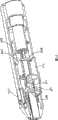
图1是表示本发明的柳叶刀组件的示意性立体图。Fig. 1 is a schematic perspective view showing a lancet assembly of the present invention.
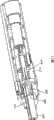
图2是为方便理解本发明柳叶刀组件的结构,切除柳叶刀套的近前侧一半的状态的示意性立体图。Fig. 2 is a schematic perspective view of a state in which the front half of the lancet holder is cut off for easy understanding of the structure of the lancet assembly of the present invention.
图3是表示切除本发明的柳叶刀组件的近前侧一半状态的示意性立体图。Fig. 3 is a schematic perspective view showing a state in which the front half of the lancet assembly of the present invention is cut off.
图4是表示装填柳叶刀组件的注射器的示意性立体图。Fig. 4 is a schematic perspective view showing a syringe loaded with a lancet assembly.
图5是表示装填柳叶刀组件后状态下的注射器的示意性立体图。Fig. 5 is a schematic perspective view showing the syringe in a state where the lancet assembly is loaded.
图6是表示构成本发明的柳叶刀组件的柳叶刀的示意性立体图。Fig. 6 is a schematic perspective view showing a lancet constituting the lancet assembly of the present invention.
图7是表示去除注射器壳体的前侧半壳的状态下,为了装填而插入柳叶刀组件途中情况的示意性立体图。Fig. 7 is a schematic perspective view showing a situation in the middle of inserting the lancet assembly for filling with the front half shell of the syringe case removed.
图8是表示切除柳叶刀套的前半侧状态下,为了装填而插入柳叶刀组件中途情况(与图7相同状态)的示意性立体图。Fig. 8 is a schematic perspective view showing a state in the middle of inserting the lancet assembly for loading (same state as in Fig. 7 ) in a state where the front half of the lancet holder is cut off.
图9与图7相同,是表示柳叶刀组件正好安装到注射器中的状态的示意性立体图。Fig. 9 is the same as Fig. 7 and is a schematic perspective view showing a state where the lancet assembly is just installed in the syringe.
图10与图8相同,是表示柳叶刀组件正好安装到注射器中的状态的示意性立体图。Fig. 10 is the same as Fig. 8 and is a schematic perspective view showing a state where the lancet assembly is just installed in the syringe.
图11与图7相同,是表示从图9的状态去除柳叶刀帽后情况的示意性立体图。Fig. 11 is the same as Fig. 7, and is a schematic perspective view showing a state in which the lancet cap is removed from the state of Fig. 9 .
图12与图8相同,是表示从图10的状态去除柳叶刀帽后情况的示意性立体图。Fig. 12 is the same as Fig. 8 and is a schematic perspective view showing a state in which the lancet cap is removed from the state of Fig. 10 .
图13与图7相同,是表示穿刺构件尖端部从柳叶刀套前端开口部飞出瞬间的情况的示意性立体图。Fig. 13 is the same as Fig. 7, and is a schematic perspective view showing the moment when the tip of the pricking member flies out from the opening at the front end of the lancet holder.
图14与图8相同,是表示穿刺构件尖端部从柳叶刀套前端开口部飞出瞬间的情况的示意性立体图。Fig. 14 is the same as Fig. 8, and is a schematic perspective view showing the moment when the tip of the pricking member flies out from the opening at the front end of the lancet holder.
图15与图7相同,是表示柳叶刀体从图13的状态后退的状态的示意性立体图。Fig. 15 is the same as Fig. 7 and is a schematic perspective view showing a state in which the lancet body is retracted from the state in Fig. 13 .
图16与图8相同,是表示柳叶刀体从图14的状态后退的状态示意性立体图。Fig. 16 is the same as Fig. 8 and is a schematic perspective view showing a state in which the lancet body is retracted from the state in Fig. 14 .
图17与图7相同,是表示柳叶刀套通过弹出器向前方移动途中状态的示意性立体图。Fig. 17 is the same as Fig. 7 and is a schematic perspective view showing a state in which the lancet holder is moving forward by the ejector.
图18是表示柳叶刀套通过弹出器向前方移动过程中状态的示意性立体图,与图8相同。Fig. 18 is a schematic perspective view showing the state in which the lancet holder is moving forward by the ejector, which is the same as Fig. 8 .
图19是表示推杆的示意性立体图。Fig. 19 is a schematic perspective view showing a push rod.
图20是表示构成注射器壳体的半壳的示意性立体图。Fig. 20 is a schematic perspective view showing half shells constituting the syringe housing.
图21是表示翼部扩展时柳叶刀组件的情况的示意性立体图。Fig. 21 is a schematic perspective view showing the state of the lancet assembly when the wings are expanded.
图22是表示弹出器的示意性立体图。Fig. 22 is a schematic perspective view showing the ejector.
图23与图2相同,是表示从注射器中排出的柳叶刀组件的示意性立体图。Fig. 23 is the same as Fig. 2, and is a schematic perspective view showing the lancet assembly ejected from the syringe.
图24是表示环状构件和撞击构件的示意性立体图。Fig. 24 is a schematic perspective view showing a ring member and a striking member.
符号说明如下:The symbols are explained as follows:
100-柳叶刀组件;102-柳叶刀套;104-前端开口部;106-前端开口部;107-后端开口部;108-后端部;110-前端部;112-凸部;114-套体;116-翼部;118-前端部;120-后端部;122-止挡部;124-倾斜面;126-后部的面;128-侧面;130-后端面;132-后端壁;140-导轨;200-柳叶刀;202-后端部;204-柳叶刀体;206-柳叶刀帽;208-弱化部分;210-穿刺构件;211-尖端部;212-突出部;218-凸部;220-凸部;221-后方面;222-突出部;300-注射器;301-片状部;302-前端开口部;303-突起;304-突出部;306、308-注射器半壳;309-壳体;310-推杆;314-前端部;316-凹部;315-座面;320、322-脚部;324-突起部;330-肩部;340-楔形构件;341-前端部;342-斜面;343-切口部规定壁;344-前隔板;345-切口部;346-突起;348-凹部;350-按钮;351-底板;354-操作按钮;356-推动器;358-后隔板;360-调节穿刺深度用转筒;361-环状构件;362-推杆后端部;363-开口部;365-撞击构件;367、367’-撞击部位;369-旋转柄;371、371’、373、373’-阶梯部。100-lancet assembly; 102-lancet cover; 104-front opening; 106-front opening; 107-rear opening; 108-rear end; 110-front end; - sleeve body; 116-wing; 118-front end; 120-rear end; 122-stopper; 124-inclined surface; 202-back end; 204-lancet body; 206-lancet cap; 208-weakening part; 210-piercing member; 211-tip; Protrusion; 218-convex; 220-convex; 221-rear aspect; 222-protrusion; 300-syringe; 301-flaky part; 308-syringe half shell; 309-housing; 310-push rod; 314-front end; 316-recess; 315-seat surface; 320, 322-foot; 324-protrusion; Component; 341-front end; 342-slope; 343-cutout prescribed wall; 344-front partition; 345-cutout; 346-protrusion; 348-recess; 350-button; 351-bottom plate; 354-operation button; 356-pusher; 358-rear partition; 360-rotating cylinder for adjusting puncture depth; 361-ring member; 362-rear end of push rod; 363-opening; 365-impacting member; Part; 369-rotating handle; 371, 371', 373, 373'-step part.
具体实施方式Detailed ways
参照附图,对本发明的柳叶刀组件以及构成其的柳叶刀和柳叶刀套,与柳叶刀组件组合使用的注射器,及,本发明的穿刺装置进行详细地说明。在本说明书中使用的关于方向的用语,将穿刺时柳叶刀移动的方向(即,穿刺构件为了穿刺穿刺部位而移动的方向,也称为穿刺方向)称为“前”,与其相反的方向为“后”,将这些方向作为基准。The lancet assembly of the present invention, the lancet and the lancet holder constituting it, the syringe used in combination with the lancet assembly, and the pricking device of the present invention will be described in detail with reference to the drawings. The terminology related to direction used in this specification refers to the direction in which the lancet moves during puncturing (that is, the direction in which the puncturing member moves to puncture the puncture site, also referred to as the puncturing direction) as "front", and the opposite direction For "back", use these directions as a reference.
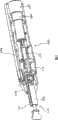
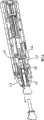
图1是表示本发明的柳叶刀组件100的示意性立体图。并且,为了了解柳叶刀组件的构造,图2表示切除柳叶刀套的近前侧一半状态的示意性立体图,另外,图3表示切除了柳叶刀组件近前侧一半的状态的示意性立体图。在这些图中,表示以组件的形式完成在柳叶刀套102中装入柳叶刀200状态。柳叶刀套102,例如作为全体为方筒形,通过从其前端开口部106向内部,从柳叶刀200的后端部202向后方插入,来组装出柳叶刀组件100。柳叶刀套102的构成是两端具有开口部106(前端)和107(后端),在穿刺时,将应该穿刺的规定部位(例如指尖)贴在前端开口部106上。FIG. 1 is a schematic perspective view showing a
图4表示装填柳叶刀组件的注射器300的示意性立体图,图5表示装填柳叶刀组件后的状态的注射器300的示意性立体图。注射器300,在由注射器半壳306和308所规定的壳体309内部的空间中,如在后面将进行详细地说明的,具有发射柳叶刀的机构。柳叶刀组件100向注射器300中的装填,是从注射器前端开口部302向其内部,通过最初插入柳叶刀套的后端部108,然后,插入柳叶刀套的大部分来实施。柳叶刀套102,具有设置在其前端部110的后方外侧的凸部(或者突起)112,其凸部112通过越过设置在注射器前端开口部302内侧后方的突出部(304,参照图7),由此完成柳叶刀组件向注射器的装填,变为图5所示的状态。FIG. 4 is a schematic perspective view of the
图6中以立体图所示的构成本发明的柳叶刀组件的柳叶刀200,具有柳叶刀体204和柳叶刀帽206,它们通过弱化部分208结合为一体。在柳叶刀200中,穿刺构件210(参照图3)跨柳叶刀体204和柳叶刀帽206,存在于它们之中,穿刺构件210的尖端部被柳叶刀帽206包围。这样的柳叶刀200,理想是插入了穿刺构件210的树脂成形品。柳叶刀体204,在其外侧具有突出部212。The
柳叶刀体204的后端部202,以嵌入到发射柳叶刀的注射器300的推杆310前端部314的方式构成,后端部202,在其外侧具有凸部218,该凸部,能够嵌入与之为互补的、设置于注射器推杆310前端部314(详细的,为后面所述的脚部)内侧的凹部316。这样的凸部和凹部的关系,与上述“相互卡合或者嵌合的2个要素”的关系相同,预测到同样的效果。也可以用凹部替代凸部,用凸部替代凹部。The
柳叶刀体204的构成,在凸部218的前方还具有另一凸部220。该凸部220的后方面221,在柳叶刀组件向注射器的安装结束的状态下,与推杆310的顶端的座面(或者窄面)315抵接,成为紧密接触的状态。The structure of the
这样的柳叶刀中,柳叶刀体204和柳叶刀帽206,以如下的方式结合到一起,即:可以利用绕穿刺构件210的延伸方向施加的互为相反方向的力,除此之外或者利用使它们沿着穿刺构件的延伸方向相对远离而作用的力,来破坏弱化部分208的方式。然后,一旦柳叶刀帽206从柳叶刀体204离开,则穿刺构件210的尖端部从柳叶刀体204露出。In such a lancet, the
构成本发明的柳叶刀组件的柳叶刀套102,具有套体114和位于其侧面,最好是相对的一对位于侧面的翼部116。该翼部理想为沿着柳叶刀套的侧面延伸(因此,实际上翼部是构成为柳叶刀套的侧面的一部分)。各翼部116,在其前端部118和后端部120之间具有向内侧突出的止挡部122。该前端部118与套体114相结合,该后端部120是自由的。其结果,从柳叶刀套102的前端开口部106插入柳叶刀200,柳叶刀体204的突出部212与止挡部122抵接,然后,如果柳叶刀200进一步向后方移动,则突出部212跃到止挡部122的倾斜面124上,对止挡部122作用向外的力,其结果,翼部116能够向外弹性扩展。The
然后,如果突出部212通过止挡部122,翼部116将恢复原来的形状,变为图2所示的状态。止挡部122后部的面126,是相对于翼部116垂直或者接近垂直的角度。其结果,在图2的状态中,即使对柳叶刀200施加向前的力,突出部212与后部的面126抵接,处于无法向前移动的状态,这样柳叶刀向前方的移动被后部的面126阻止。因此,突出部212一旦越过止挡部120向其后方移动,突出部212就不能越过止挡部120向前方移动。在突出部212刚好越过止挡部120的状态下,如图2所示,柳叶刀体的后端部202和位于其前方的2个凸部(或者突出部)218、220,构成为处于从柳叶刀套102后端开口部107向后方(即外侧)突出的状态。Then, if the protruding
柳叶刀帽206,其前端部214形成柄部,能够在如上所述弱化部分208遭破坏时被夹住,在其后方具有突出部216。突出部216,如图所示最好为帽沿状(或凸缘状),与规定柳叶刀套102的前端开口部106的部分抵接,柳叶刀200不能相对于柳叶刀套102再向后方移动。The
因此,如图2所示,在完成组装的柳叶刀组件100中,即使有向前的力作用于柳叶刀200,柳叶刀200也不能从柳叶刀套102前端开口部106脱出,另外,即使有向后的力作用于柳叶刀200,也不能从后端开口部107脱出。Therefore, as shown in FIG. 2, in the assembled
如上所述,组装后的柳叶刀组件,从图4所示的注射器300的前端开口部302插入,柳叶刀的突出部112越过位于注射器前端开口部后方的突出部304,变为图5的状态,在该状态下结束装填。As mentioned above, the assembled lancet assembly is inserted from the
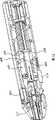
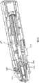
图7和图8是表示为了装填而将柳叶刀组件插入注射器的中途情况的立体图。为了容易理解柳叶刀组件100和注射器300关系以及注射器内部的情况,图7中以去除注射器壳体的前侧半壳308的状态予以表示。另外,为了理解柳叶刀套102内柳叶刀200的情况,且为了容易理解后面将要叙述的穿刺深度调节机构,图8中以切除柳叶刀套102前半侧的状态进行表示,为了理解发射柳叶刀的推杆310(图19表示放大图)的情况,以切除后面将要叙述的弹出器312近前侧一半的状态表示,另外,以切除后面将要叙述的调节穿刺深度用转筒360的近前侧一半的状态表示。7 and 8 are perspective views showing the state of inserting the lancet assembly into the syringe for filling. In order to easily understand the relationship between the
如图19所示,推杆310,其前端部被分成2部分,以规定其中间有小的间隙318的方式构成第1脚部320和第2脚部322。推杆,是例如塑料材料的成形品,其结果,第1脚部和第2脚部以可以弹性变形的方式构成。例如,对于这些脚部,如箭头所示,如果力向外作用,则这些脚部向外扩展,间隙变宽。As shown in FIG. 19, the front end portion of the
因此,如图7所示,将图1所示的柳叶刀组件100,插入注射器300,图7的状态之后,柳叶刀体204的后端部202,最初与图19所示的状态下的推杆前端部314的窄面315抵接。然后,如果意欲插入柳叶刀组件,柳叶刀体204的后端部202会对窄面315作用向后方的推压力。由于窄面倾斜,所以该力也作用有沿箭头所示的方向的力,其结果,脚部320和322向外弹性扩展。Therefore, as shown in FIG. 7, the
如果这样扩展,柳叶刀体204的后端部202能够进一步向后方移动,柳叶刀体204后端部202的凸部218被嵌入到凹部316,同时向外侧扩展的脚部多少有欲恢复原来形状的趋势,后端部202由此被脚部320和322夹持,紧密地嵌入在间隙318内。此时,柳叶刀体的突出部220,与设置在推杆310前端的座面(或者窄面)315抵接,处于紧密接触的状态。If expanded in this way, the
这样,与图7和图8相同,图9和图10表示柳叶刀组件100正好被装填到注射器300中的状态。由图10可知,柳叶刀体204突出部220的后方倾斜面221与推杆310前端的窄面315抵接。In this way, FIGS. 9 and 10 show a state where the
推杆310,在其中间部分的周围所设突起324的后方(例如突起324和后方隔板358之间),具有配置在推杆周围的发射弹簧(图中没有表示)。在将柳叶刀组件装填到注射器中时,与推杆前端部314抵接的柳叶刀的后端部202使推杆后退,压缩发射弹簧。此时,突起324,在轴326的更靠后方处作用有向下力的触发杆328的下方,一边克服该向下的力而作用稍微顶起触发杆的力,一边后退。The
之后,在突起324通过位于触发杆的后端的肩部330下方之后,触发杆的肩部330(受上述的朝下的力作用)突然向下移动,如图9所示,突起部324变为被肩部330卡止的状态。在该状态下,即使解除将推杆推向后方的力,也不受由被压缩的发射弹簧所作用的向前的力作用于推杆的影响,由被肩部330阻止突起部324向前方的移动,保持图9的状态。即,对于柳叶刀的发射,处于所谓的待击发的状态。Then, after the
这样,在突起部324被位于触发杆后端的肩部330卡止的状态下,最好推杆310的前端部314的间隙(或空间)318不能扩展,因此最好使脚部320、322不向外侧扩展变形。为了防止这样的扩展,最好是设置在壳体上的前隔板344具有切口部345,而在突起部324被卡止的状态下,规定该切口部345的壁343正好包围推杆310的前端部314,其结果使得推杆的前端部314不发生扩展。Like this, under the state that protrusion 324 is locked by the
并且,在图示的方式中,片状部301从位于触发杆后端的肩部端面的上缘向后方延伸出来。该片状部301,如后面将叙述得那样,为了发射柳叶刀,按入按钮350时,片状部301与壳体内的突起303抵接产生弹性变形,利用该变形起到作用欲推回按钮的力的功能(参照图11)。In addition, in the illustrated form, the
这样,使柳叶刀体的后端部后退,与推杆的前端部抵接,然后,如果进一步使柳叶刀体后退,柳叶刀体的后端部会嵌入到推杆的前端部。并且,该柳叶刀体后端部的嵌入,也可以在柳叶刀体后端部使推杆后退,而无法继续后退的状态下产生。在其他方式中,也可以首先发生嵌入,然后,通过使柳叶刀体后退来使推杆后退。In this way, the rear end of the lancet body is retracted to abut against the front end of the plunger, and when the lancet body is further retracted, the rear end of the lancet body fits into the front end of the plunger. In addition, the insertion of the rear end of the lancet body may occur in a state where the push rod is retracted at the rear end of the lancet body and cannot be further retracted. Alternatively, embedding may occur first and then the plunger is retracted by retracting the lancet body.
在图9和图10所示的柳叶刀组件100向注射器300的装填结束的状态下,应该特别注意的是,柳叶刀套102两侧的翼部116处于被向外推展的状态。像这样翼部被向外推展,是因为在注射器的内部设置了1对楔形构件340来作为翼部扩张构件的缘故。该楔形构件340,具有相互分离且尖端细的形状(即,前方尖),其结果,规定了向注射器前方倾斜的斜面342。When the filling of the
该楔形构件340,由图20所示的注射器半壳306的示意性立体图知,被设置在半壳306上。在图示的方式中,作为其它构件形成的楔形构件被嵌入到半壳306中。在柳叶刀组件100向注射器300内的装填结束之前,楔形构件340的前端部341,挤入柳叶刀套102翼部116的自由的后端部120的内侧。然后,如果进一步使柳叶刀组件后退,翼部116后端部会跃上楔形构件340的斜面342上,并滑动上升,其结果,翼部116向外弹性扩展。这样,如果设置楔形构件,由于只要将柳叶刀组件向后方插入装填,就能自动扩展翼部116,便于使用。The
图21是表示翼部116扩展时的柳叶刀组件100的情况的示意性立体图。并且,在图21中,为了理解内部柳叶刀的情况,以切除柳叶刀套102的近前侧一半的面的状态进行表示。可以很容易理解,随着翼部116向外侧扩展,止挡部122的位置与不扩展时(例如图2所示的状态)相比,向外侧移动。其结果,止挡部122,已经不能起到作为止挡部的功能。因此,在图21状态下,柳叶刀要向前方移动时,柳叶刀体204突出部212不会碰到止挡部122,不会妨碍柳叶刀向前方的移动。FIG. 21 is a schematic perspective view showing the state of the
如上所述,在柳叶刀组件100向注射器300的装填结束后,去除柳叶刀帽206。柳叶刀体204和柳叶刀帽206通过绕穿刺构件的延伸方向施加的互为相反方向的力,或者使它们以沿着穿刺构件的延伸方向相对远离的方式拉开,从而破坏弱化部分,然后,如图9和图10的箭头所示,当柳叶刀帽206从柳叶刀体204离开后,穿刺构件210的尖端部211从柳叶刀体204露出(参见图12)。这样,柳叶刀帽,起到作为事先覆盖穿刺构件尖端部的保护帽的功能。As described above, after the filling of the
并且,为了绕延伸方向施加互为相反方向的力,容易扭断柳叶刀帽206,柳叶刀体204采取不能在柳叶刀套内旋转的剖面形状,柳叶刀帽206位于柳叶刀套内的后方部分,最好采用能够在柳叶刀套内旋转的剖面形状。例如,在柳叶刀套内柳叶刀体和柳叶刀帽占据的空隙的剖面为矩形剖面时,只要也将柳叶刀体做成不能在其剖面上旋转的矩形,并将柳叶刀帽的后方部分做成圆形剖面即可。In addition, in order to apply forces in opposite directions around the extension direction, the
图11和图12与图7和图8相同,示意性示出由图9和图10的状态除去柳叶刀帽206的情况。由图12可知,穿刺构件210的尖端部211在柳叶刀套内露出。与图11和图12相比可得知,穿刺构件露出的尖端部的最尖端部,位于远离柳叶刀套102前端开口部106的位置。Fig. 11 and Fig. 12 are the same as Fig. 7 and Fig. 8, and schematically show the state of removing the
如上所述,由于推杆的突起部324被卡止在触发杆的肩部330上,使得发射弹簧以被压缩状态保持。因此,在图11和图12所示的状态中,将待穿刺的规定部位,例如指尖贴到柳叶刀套102前端开口部106,然后,通过解除触发杆328的卡止状态,使被压缩的发射弹簧瞬间伸长,其结果,推杆310向前方移动,由此,穿刺构件尖端部211所露出的柳叶刀体204瞬时移动到前方,从柳叶刀套102的前端开口部106飞出,穿刺贴在此处的规定部位。As noted above, the firing spring is held in a compressed state due to the
此外,卡止状态的解除,能够通过压低设置在触发杆前端部的按钮350实施。该触发杆,能够绕旋转轴326旋转,可以在按钮350下方配置压缩弹簧,尤其是在没有外力作用时,通过此弹簧,可以对触发杆的按钮和从轴起向前的部分产生向上(即向外)的力的作用,相反,对触发杆的从轴向后方的部分产生向下(即向内)的力的作用。此外,如上所述,可以利用片状301实现同样的作用,但使用这样的弹簧增加了作用的可靠性。In addition, the release of the locked state can be performed by pressing down the
图13和图14与图7和图8相同,示意性表示穿刺构件尖端部211从柳叶刀套102前端开口部106飞出瞬间的情况,由图14可知,由于通过楔形构件340使翼部116保持向外侧扩展的状态,因此柳叶刀体204突出部212,在止挡部120内侧不能被其阻止,进一步向前方移动。Fig. 13 and Fig. 14 are the same as Fig. 7 and Fig. 8, which schematically show the moment when the
此外,虽未图示,但在推杆310的突起324和设置在壳体内侧所设的前隔板344之间,在推杆310的周围配置有返回弹簧。为了发射柳叶刀,通过推杆310向前方移动,使得该弹簧被压缩。其结果,穿刺构件尖端部211从柳叶刀套102前端开口部106突出,穿刺结束后的瞬间,或者在前后很短的时间,处于被充分压缩的状态,然后,向原来的形状伸长。由此,穿刺结束后,柳叶刀体204后退。In addition, although not shown, a return spring is arranged around the
图15和图16,与图7和图8相同,示意性表示柳叶刀体204由图13和图14状态后退后的状态。比较图12和图16容易理解,在图16的状态下,因返回弹簧的伸长而以很强惯性后退的推杆的突起部324越过设置在触发杆下侧的小的突起346,变为嵌入到位于其后面的凹部348中的状态。这样通过设置突起346和凹部348,缓和后退推杆的惯性的同时,即使产生返回弹簧伸长后收缩这样的振动,推杆的突起324也不能越过触发杆的突起346而向前方移动,其结果,减少了能够产生第2次穿刺这样的可能性。FIGS. 15 and 16 are the same as FIGS. 7 and 8 , schematically showing a state in which the
此外,如上所述,在突起部324嵌入到位于触发杆下侧(图示的方式中,与存在按钮350侧相反一侧)的凹部348而发生卡合的状态中,即使对推杆作用有向前得力,位于凹部348前方的突起346构成为使该卡合状态不被解除。具体的说,规定突起346的后方面347(参照图14),在垂直于穿刺方向或者接近垂直方向上延伸,另一方面,规定突起346的前方面349(参照图13),规定在相对穿刺方向倾斜的方向上延伸的斜度。另外,为了发射柳叶刀,如果压低触发按钮350,触发杆绕轴326旋转,突起346移动到上方。In addition, as described above, in the state in which the
其结果,突起346,没有位于推杆的突起部324所向前移动的轨道上,不会阻碍推杆向前方的移动。然后,如果解除对触发按钮所施加的力,触发杆就恢复原来的状态。As a result, the
如果使用这样的触发杆,在柳叶刀组件从注射器排出时,由弹出器对柳叶刀套施加向前的力,此力,即使作用于推杆,也能维持突起部324和突起346的卡合关系,或者突起部324嵌入凹部348的关系。为了使这样的关系更可靠,如图19所示,规定推杆的突起部324的前方面325,以相对于推杆移动方向垂直或者接近垂直的角度延伸,另外,后方面327,倾斜延伸形成斜面。If such a trigger lever is used, when the lancet assembly is ejected from the syringe, the ejector exerts a forward force on the lancet holder, which force, even if acting on the push rod, can maintain the alignment of the
通过组合规定这样的推杆突起部324的垂直的前方面325和倾斜的后方面327,以及规定位于如上所述的触发杆的下侧的突起346的倾斜的前方面349和垂直的后方面347,可以将推杆突起部324构成为:能够容易越过触发杆的突起346向后方移动,但是一旦越过,推杆突起部324,越过触发杆的突起346,不能容易向前方移动。实际上,为了越过,需要对突起部以及突起的至少一方的部分进行实质性地变形或者破坏。By combining a vertical
如图7~图16所示,本发明的注射器300,在其下侧具有弹出器312。图22是示意性表示该弹出器的立体图。弹出器312,由底板351和推动器352构成,被配置在注射器壳体309的下侧。通过将设置在底板351下侧的操作按钮354从注射器的外部沿箭头方向滑动,可以使底板351在注射器300内部向前方移动。例如,在注射器壳体内侧设置导向槽,也可以在底板外侧设置能够在导向槽内移动的导轨。As shown in FIGS. 7 to 16 , the
推动器352,柳叶刀组件100向注射器300的装填结束时刻,以其前端部356与柳叶刀套102的后端部108抵接,或者大致抵接的方式来构成。图7、图8与图9~图16相比可明确得出,图示的方式如此被构成。其他方式中,前端部356,从柳叶刀套102的后端部108离开。此外,推动器352最好构成为,只将包括柳叶刀套102的套体114的相对着的侧面128、且优选为没有翼部的侧面的后端缘的面130推向前方。The
穿刺结束,变为图15和图16所示的状态后,通过将弹出器的按钮354滑动到前方,由推动器356将柳叶刀套102的后端面130推向前方。向前方推的力,如果超过柳叶刀套的突出部112能够越过注射器300前端开口部302内侧的突起304的力这一阈值,柳叶刀套102即向前方移动。After the puncturing is completed and the state shown in FIGS. 15 and 16 is changed, the
此时,如上所述,推杆向前方的移动,被触发杆的突起346和凹部348阻止。因此,由弹出器施加的力,最初被用于柳叶刀套102向前方的移动,在后来,如后面所述,被用于柳叶刀体204的后端部202从推杆前端部的脱离。由于柳叶刀套102内柳叶刀体204后端部的凸部(最好是设置在周围的周状突起)218,是被注射器推杆的前端部314的脚部320和322夹持的状态,故不能向前方移动。At this time, as described above, the forward movement of the push rod is prevented by the
这样如果柳叶刀套102向前方移动,翼部116的后端部120,从楔形构件340离开,其结果,翼部116向原来的形状弹性变形。即,扩展的翼部关闭,成为图1所示的状态。由此,设置在翼部116内侧的止挡部122,重新起到作为止挡部的功能。即,柳叶刀体204突出部212,在柳叶刀套内不能越过止挡部122向前方移动。In this way, when the
因此,由于穿刺构件210尖端部211露出状态下的柳叶刀体204向前方的移动被止挡部122阻止,穿刺构件的尖端部211只能从柳叶刀套102前端开口部106向前方前进到足够内侧的位置。当然,突出部212也不能从柳叶刀套102后端开口部向后方脱出。这样,当柳叶刀套102向前方移动,翼部116恢复原来的形状后,柳叶刀体,以突出的尖端部211存在于距前端开口部106足够靠后的位置的状态,保持在柳叶刀套102内。Therefore, since the forward movement of the
图17和图18,与图7和图8相同,示意性表示了柳叶刀套102通过弹出器312向前方移动中途的状态。如上所述,柳叶刀套102的翼部116恢复原来的形状。因此,柳叶刀体204的突出部212,由翼部116的止挡部122阻止向前方的移动,另外,通过规定柳叶刀套102的后端开口部107的壁面132,阻止向后方移动。FIG. 17 and FIG. 18 are the same as FIG. 7 and FIG. 8 , schematically showing the state in which the
如图所示,如果柳叶刀套102向前方移动,柳叶刀体204的突出部212,与规定柳叶刀套102后端开口部107的壁132抵接。此外,推杆如上所述,通过触发杆,处于阻止其向前方移动的状态。在这样的状态下,施加力以使推动器356向更前方移动。当向前方施加力,则向前的力传递到推杆310的脚部320和322所保持的,即,所嵌入的柳叶刀体的突起218上,其结果,突起218意欲将脚部撑开。一旦该向前的力超过某一阈值,脚部向外弹性扩展,因此,导致放开嵌入的突起218和柳叶刀体204的后端部。此外,图15~18所示的状态中,推杆的突起部324,是被截留在触发杆下侧的凹部328内的状态,由于推杆前端部314的位置,位于比壳体前隔板344更靠前,脚部320和322的扩展,不会受前隔板的规定开口部的壁阻碍。As shown in the figure, when the
从图示的状态起,如果使弹出器312进一步向前方移动,柳叶刀套102,进而,柳叶刀组件,能够从弹出器300的前端开口部302排出。排出的柳叶刀组件,由柳叶刀套102和尖端部211露出的穿刺构件210构成,图23与图2一样表示其状态。为了能够容易理解,与图2的不同点,是图23中不存在柳叶刀帽206。如上所述,柳叶刀体206的突出部212は,被夹在止挡部122和后端开口部的壁132,而无法越过它们进行移动。From the illustrated state, if the
由图23能够容易理解,在柳叶刀套102中,即使柳叶刀体204移动到最前方时,穿刺构件的最尖端部,也充分远离柳叶刀套102前端开口部106。因此,操作图23所示的状态的柳叶刀套102时,与露出的穿刺构件相关的危险性大幅度减少。As can be easily understood from FIG. 23 , in the
此外,柳叶刀套和柳叶刀体最好具有使穿刺时柳叶刀套102内部的柳叶刀体204顺滑移动的机构。例如,由图23能够理解,本发明的柳叶刀的柳叶刀体204,具有不同的突出部222,柳叶刀套102侧面的内侧具有导轨140,来夹着其突出部。通过组合这样的突出部和导轨,能够构成可顺滑地进行在柳叶刀套102内部的柳叶刀体204的移动的导向机构。In addition, the lancet holder and the lancet body preferably have a mechanism for smoothly moving the
上述本发明的柳叶刀组件,注射器,除了穿刺构件,弹簧之外,最好由树脂形成,尤其理想的是由树脂的成形品构成,除了制造的容易性之外,利用树脂的弹性,适合于翼部的功能,推杆的脚部功能,柳叶刀套突出部112和注射器前端开口部突起之间的关系。The above-mentioned lancet assembly and syringe of the present invention are preferably made of resin, in addition to the piercing member and spring, and are particularly preferably made of resin molded products. In addition to the ease of manufacture, the elasticity of the resin is suitable for The function of the wings, the function of the feet of the push rod, and the relationship between the
本发明的注射器的一个方式中,在注射器壳体的后隔板358后侧,与其邻接,具有调节穿刺深度用转筒360(例如参照图7)。在该转筒360前端的内部,配置具有开口部363的穿刺深度调节环状构件361(这些最好结合为一体),推杆的后端部362贯通延伸于开口部363,在推杆的后端安装撞击构件365。并且,环状构件能够在该推杆周围旋转。具体的说,通过嵌入在转筒360后方的旋转柄369,可以使转筒360和环状构件361在推杆的周围旋转。In one embodiment of the syringe of the present invention, a
图24省略了推杆(由虚线只表示延伸方向),是表示位于推杆周围的环状构件361和配置在推杆后端的撞击构件365的示意性立体图。环状构件361的穿刺方向的长度(a)沿着其圆周方向,连续的或者阶梯状变化。在图示的方式中,穿刺方向的长度呈阶梯状,例如a1,a2和a3变化着。撞击构件365,在上下具有撞击部位367和367’,如果发射柳叶刀,推杆向前方移动,撞击构件365,如箭头所示,向穿刺方向移动,撞击环状构件。FIG. 24 is a schematic perspective view showing the
例如在图24所示的方式中,如果推杆向前方移动,撞击部位367,撞击到穿刺方向的长度为al的阶梯371,撞击部位367’,撞击到穿刺方向的长度为al的阶梯371’。即,撞击构件的撞击部位,撞击构成环状构件的后方端面一部分的阶梯中的1个。在该状态下,如图示的箭头,将柄369向(从图面的左侧看)右稍微旋转,则上侧的撞击部位367移动到前侧,撞击部位367’移动到相向的一侧。For example, in the manner shown in Figure 24, if the push rod moves forward, the
其结果,撞击部位367,撞击到穿刺方向的长度为a2的阶梯373,撞击部位367’,撞击到穿刺方向的长度为a2的阶梯373’。能够容易理解,由于撞击部位所撞击的环状构件在穿刺方向上的长度不同,例如由于在阶梯371和阶梯373中,穿刺方向的长度不同,能够改变推杆向前方移动的距离,即,改变穿刺深度。As a result, the
此外,撞击构件365和环状构件361至少一方,由富有弹性的材料,例如硅,氨基甲酸乙酯等形成,具有减缓撞击特性时,减缓这些撞击时的撞击,其结果,减缓了穿刺时使用者所感觉到的撞击故而较为优选。In addition, at least one of the
产业上的可利用性Industrial availability
本发明的柳叶刀,柳叶刀套和由它们构成的柳叶刀组件,及注射器,能够提供更安全更简便的装置。The lancet, the lancet holder and the lancet assembly made of them, as well as the syringe of the present invention can provide a safer and more convenient device.
Claims (26)
Applications Claiming Priority (3)
| Application Number | Priority Date | Filing Date | Title |
|---|---|---|---|
| JP2006102165 | 2006-04-03 | ||
| JP102165/2006 | 2006-04-03 | ||
| PCT/JP2007/057381WO2007114423A1 (en) | 2006-04-03 | 2007-04-02 | Lancet assembly |
Publications (2)
| Publication Number | Publication Date |
|---|---|
| CN101410059A CN101410059A (en) | 2009-04-15 |
| CN101410059Btrue CN101410059B (en) | 2011-08-03 |
Family
ID=38563687
Family Applications (2)
| Application Number | Title | Priority Date | Filing Date |
|---|---|---|---|
| CNA2007800114566APendingCN101410058A (en) | 2006-04-03 | 2007-03-26 | Lancet assembly |
| CN2007800115709AExpired - Fee RelatedCN101410059B (en) | 2006-04-03 | 2007-04-02 | Lancet Components |
Family Applications Before (1)
| Application Number | Title | Priority Date | Filing Date |
|---|---|---|---|
| CNA2007800114566APendingCN101410058A (en) | 2006-04-03 | 2007-03-26 | Lancet assembly |
Country Status (10)
| Country | Link |
|---|---|
| US (1) | US20090228035A1 (en) |
| EP (1) | EP2008587A4 (en) |
| JP (1) | JPWO2007114423A1 (en) |
| KR (1) | KR20090009821A (en) |
| CN (2) | CN101410058A (en) |
| BR (1) | BRPI0709938A2 (en) |
| CA (1) | CA2647820A1 (en) |
| MX (1) | MX2008012630A (en) |
| RU (1) | RU2008143346A (en) |
| WO (1) | WO2007114423A1 (en) |
Families Citing this family (14)
| Publication number | Priority date | Publication date | Assignee | Title |
|---|---|---|---|---|
| JP4642082B2 (en)* | 2005-09-29 | 2011-03-02 | 泉株式会社 | Lancet assembly and lancing device |
| CA2647791A1 (en)* | 2006-04-03 | 2007-10-11 | Izumi-Cosmo Company, Limited | Lancet assembly |
| CN101466310B (en)* | 2006-06-13 | 2011-06-15 | 泉株式会社 | Lancet assembly |
| US7909842B2 (en)* | 2006-06-15 | 2011-03-22 | Abbott Diabetes Care Inc. | Lancing devices having depth adjustment assembly |
| US9566028B2 (en)* | 2009-09-10 | 2017-02-14 | Asahi Polyslider Company, Limited | Lancet pricking device |
| US9044177B2 (en)* | 2009-10-07 | 2015-06-02 | Asahi Polyslider Company, Limited | Lancet pricking device |
| CN104519813A (en) | 2010-12-29 | 2015-04-15 | 澳擞技术有限责任公司 | Motor-driven tools for orthopedic impact |
| US8695726B2 (en) | 2010-12-29 | 2014-04-15 | Medical Enterprises LLC | Electric motor driven tool for orthopedic impacting |
| EP3007623B1 (en)* | 2013-06-10 | 2019-02-20 | Facet Technologies, LLC | Lancet needle with alignment and retention notch |
| TWM482374U (en)* | 2014-03-27 | 2014-07-21 | Medifun Corp | Press type needle retreating mechanism for lancing device |
| WO2015159845A1 (en)* | 2014-04-16 | 2015-10-22 | 株式会社旭ポリスライダー | Lancet |
| CN104665845A (en)* | 2015-03-10 | 2015-06-03 | 王振民 | Improved structure of top trigger disposable safety blood collector |
| CN111419243B (en)* | 2020-04-21 | 2021-11-16 | 苏州施莱医疗器械有限公司 | Blood sampling pen capable of loading and adjusting depth by using tail handle |
| CN111419244B (en)* | 2020-04-21 | 2022-04-19 | 苏州施莱医疗器械有限公司 | Blood sampling pen utilizing tail handle to be loaded in chamber and adjusting depth |
Family Cites Families (16)
| Publication number | Priority date | Publication date | Assignee | Title |
|---|---|---|---|---|
| DE4212315A1 (en)* | 1992-04-13 | 1993-10-14 | Boehringer Mannheim Gmbh | Blood lancet device for drawing blood for diagnostic purposes |
| JP2561697Y2 (en) | 1992-08-28 | 1998-02-04 | アプルス株式会社 | Lancet |
| US5628765A (en)* | 1994-11-29 | 1997-05-13 | Apls Co., Ltd. | Lancet assembly |
| US6168606B1 (en)* | 1999-11-10 | 2001-01-02 | Palco Labs, Inc. | Single-use lancet device |
| CN101366633B (en)* | 2001-01-19 | 2011-03-30 | 松下电器产业株式会社 | Lancet-integrated sensor, measurement device, and biosensor case |
| GB0103977D0 (en)* | 2001-02-17 | 2001-04-04 | Owen Mumford Ltd | Improvements relating to skin prickers |
| CN1332632C (en)* | 2001-07-11 | 2007-08-22 | 爱科来株式会社 | Lancets and Piercing Devices |
| JP2004290477A (en)* | 2003-03-27 | 2004-10-21 | Terumo Corp | Ingredient measuring device and kit |
| US7905898B2 (en)* | 2003-08-15 | 2011-03-15 | Stat Medical Devices, Inc. | Adjustable lancet device and method |
| US7452366B2 (en)* | 2004-05-06 | 2008-11-18 | Eumed Biotechnology Co., Ltd. | Safety lancet device |
| WO2006004664A1 (en)* | 2004-06-25 | 2006-01-12 | Facet Technologies, Llc | Low cost safety lancet |
| EP1815792B1 (en)* | 2004-10-25 | 2016-06-01 | ARKRAY, Inc. | Lancet and lancet device with the same |
| JP4642082B2 (en)* | 2005-09-29 | 2011-03-02 | 泉株式会社 | Lancet assembly and lancing device |
| CA2647791A1 (en)* | 2006-04-03 | 2007-10-11 | Izumi-Cosmo Company, Limited | Lancet assembly |
| CN101466310B (en)* | 2006-06-13 | 2011-06-15 | 泉株式会社 | Lancet assembly |
| US20090299398A1 (en)* | 2006-06-13 | 2009-12-03 | Izumi-Cosmo Company, Limited | Lancet Assembly and Pricking Device |
- 2007
- 2007-03-26CNCNA2007800114566Apatent/CN101410058A/enactivePending
- 2007-04-02EPEP07740817Apatent/EP2008587A4/ennot_activeWithdrawn
- 2007-04-02KRKR1020087025905Apatent/KR20090009821A/ennot_activeWithdrawn
- 2007-04-02BRBRPI0709938-0Apatent/BRPI0709938A2/ennot_activeIP Right Cessation
- 2007-04-02CNCN2007800115709Apatent/CN101410059B/ennot_activeExpired - Fee Related
- 2007-04-02RURU2008143346/14Apatent/RU2008143346A/ennot_activeApplication Discontinuation
- 2007-04-02MXMX2008012630Apatent/MX2008012630A/ennot_activeApplication Discontinuation
- 2007-04-02CACA002647820Apatent/CA2647820A1/ennot_activeAbandoned
- 2007-04-02WOPCT/JP2007/057381patent/WO2007114423A1/enactiveApplication Filing
- 2007-04-02JPJP2008508695Apatent/JPWO2007114423A1/enactivePending
- 2007-04-02USUS12/225,873patent/US20090228035A1/ennot_activeAbandoned
Non-Patent Citations (1)
| Title |
|---|
| JP特开2004-290477A 2004.10.21 |
Also Published As
| Publication number | Publication date |
|---|---|
| BRPI0709938A2 (en) | 2011-08-02 |
| RU2008143346A (en) | 2010-05-10 |
| EP2008587A1 (en) | 2008-12-31 |
| EP2008587A4 (en) | 2010-08-04 |
| CA2647820A1 (en) | 2007-10-11 |
| CN101410058A (en) | 2009-04-15 |
| KR20090009821A (en) | 2009-01-23 |
| MX2008012630A (en) | 2008-10-13 |
| CN101410059A (en) | 2009-04-15 |
| US20090228035A1 (en) | 2009-09-10 |
| WO2007114423A1 (en) | 2007-10-11 |
| JPWO2007114423A1 (en) | 2009-08-20 |
Similar Documents
| Publication | Publication Date | Title |
|---|---|---|
| CN101410059B (en) | Lancet Components | |
| CN101466310B (en) | Lancet assembly | |
| KR100570387B1 (en) | Improved Skin Flickr | |
| WO2007018215A1 (en) | Needle insertion device, and lancet assembly and injector assembly that form the same | |
| JP4642082B2 (en) | Lancet assembly and lancing device | |
| KR20080110859A (en) | Lancet assembly | |
| CN103153187B (en) | Puncture device, and lancet assembly and injector assembly constituting same | |
| JP5469397B2 (en) | Puncture device and lancet assembly and injector assembly constituting the same | |
| HK1131024A (en) | Lancet assembly | |
| HK1125812A (en) | Lancet assembly | |
| JP2023159452A (en) | Injector and lancet assemblies and lancing devices | |
| HK1128399A (en) | Lancet assembly | |
| HK1115521A (en) | Needle insertion device, and lancet assembly and injector assembly that form the same |
Legal Events
| Date | Code | Title | Description |
|---|---|---|---|
| C06 | Publication | ||
| PB01 | Publication | ||
| C10 | Entry into substantive examination | ||
| SE01 | Entry into force of request for substantive examination | ||
| C14 | Grant of patent or utility model | ||
| GR01 | Patent grant | ||
| C17 | Cessation of patent right | ||
| CF01 | Termination of patent right due to non-payment of annual fee | Granted publication date:20110803 Termination date:20120402 |