CN101408986B - Image encoding apparatus and image encoding method - Google Patents
Image encoding apparatus and image encoding methodDownload PDFInfo
- Publication number
- CN101408986B CN101408986BCN2008101693774ACN200810169377ACN101408986BCN 101408986 BCN101408986 BCN 101408986BCN 2008101693774 ACN2008101693774 ACN 2008101693774ACN 200810169377 ACN200810169377 ACN 200810169377ACN 101408986 BCN101408986 BCN 101408986B
- Authority
- CN
- China
- Prior art keywords
- frame
- mentioned
- frame rate
- unit
- quantization amplitude
- Prior art date
- Legal status (The legal status is an assumption and is not a legal conclusion. Google has not performed a legal analysis and makes no representation as to the accuracy of the status listed.)
- Expired - Fee Related
Links
Images


Classifications
- G—PHYSICS
- G06—COMPUTING OR CALCULATING; COUNTING
- G06T—IMAGE DATA PROCESSING OR GENERATION, IN GENERAL
- G06T9/00—Image coding
Landscapes
- Engineering & Computer Science (AREA)
- Multimedia (AREA)
- Physics & Mathematics (AREA)
- General Physics & Mathematics (AREA)
- Theoretical Computer Science (AREA)
- Compression Or Coding Systems Of Tv Signals (AREA)
- Compression, Expansion, Code Conversion, And Decoders (AREA)
Abstract
Translated fromChinese
Description
Translated fromChinese本发明申请是申请人于2003年4月24日提交的申请号为03122270.6, The application for the present invention is that the applicant's application number submitted on April 24, 2003 is 03122270.6,
发明名称为“图像编码装置及图像编码方法”的分案申请。 A divisional application titled "Image Coding Device and Image Coding Method". the
技术领域technical field
本发明涉及一种图像编码技术及图像解码技术,尤其是涉及一种使用可变位速率方式或可变帧速率方式的图像编码技术。 The present invention relates to an image encoding technique and an image decoding technique, in particular to an image encoding technique using a variable bit rate method or a variable frame rate method. the
背景技术Background technique
以前,MPEG(Moving Picture Expert Group)标准等图像编码技术中控制位速率的方式之一中有可变位速率(Variable Bit Rate)方式。这主要是所谓为了遵守存储编码数据的缓冲存储器的容量等约束、或在记录媒体中记录时的映像记录时间的约束,允许位速率随着编码图像的复杂性而局部变化,并将规定时间长度(例如1秒)中的发生比特数抑制在一定数量以内的控制方式。即,通过对编码困难的画面(シ一ン)多产生编码用比特(位速率变高),在编码容易的画面中减少发生的比特数(位速率变低),根据画面来控制分配的比特数。即,将一定时间内发生的比特数保持为恒定(即在缓冲存储器容量的约束或记录时间的约束范围内),可再现高画质图像地进行编码(例如参照特开2001-25015号公报)。 In the past, the variable bit rate (Variable Bit Rate) method was one of the methods of controlling the bit rate in the image coding technology such as the MPEG (Moving Picture Expert Group) standard. This is mainly because the bit rate is allowed to locally vary with the complexity of the coded image, and the length of time is specified in order to comply with constraints such as the capacity of the buffer memory that stores the encoded data, or the constraints of the image recording time when recording on the recording medium. (For example, 1 second) The control method suppresses the number of occurrence bits within a certain number. That is, by generating more bits for encoding (increasing the bit rate) for difficult-to-encode pictures, reducing the number of generated bits (lowering the bit rate) in pictures that are easy to encode, and controlling the allocated bits for each picture number. That is, the number of bits generated within a certain period of time is kept constant (that is, within the constraints of buffer memory capacity or recording time), and encoding can be performed to reproduce high-quality images (for example, refer to JP-A-2001-25015) . the
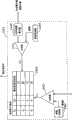
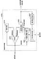
用图1的图像编码装置100来说明使用上述现有可变位速率方式的图像编码装置。该图像编码装置100由正交变换部105、量化部106、可变长编码部107、逆量化部108、逆正交变换部109、帧存储器102、动作检测部103、动作补偿部104及位速率控制部110构成。 An image coding apparatus using the above-mentioned conventional variable bit rate method will be described using the
正交变换部105以宏块(macro block)单位对接收的被编码帧信号101(图像信号数据)进行离散余弦变换(DCT:Discrete Cosine Transform),生成DCT系数后,输出到量化部106。这里,在帧内编码模式下对I(帧内编 码Intra coded)图像的帧进行DCT运算。根据时间上位于过去的I图像或P图像,在前向预测编码模式下对P(Predictive coded)图像的帧进行DCT运算。根据时间上位于前后的I图像或P图像,在双向预测编码模式下对B(Bidirectionally)图像的帧进行DCT运算。 The
量化部106对于从正交变换部105输入的DCT系数,通过每个宏块中从位速率控制部110接收的量化幅度(也可以是量化参数)进行量化,输出到可变长编码部107及逆量化部108。可变长编码部107对从量化部106输入的量化的DCT系数等进行可变长编码及复用,输出到输出缓冲器(未图示)。 The
逆量化部108对从量化部106接收的量化的DCT系数进行逆量化运算,输出到逆正交变换部109。逆正交变换部109根据从逆量化部108输入的逆量化的DCT系数,进行逆正交变换运算,再现图像信号数据,输出到帧存储器102。 The
帧存储器102将I图像或P图像的解码后图像信号数据与动作(运动)补偿部104生成的动作补偿数据相加后进行存储。动作检测部103根据帧存储器102中存储的参照图像来检测运动矢量,将表示该运动矢量的数据输出到动作补偿部104。 The
动作补偿部104为了编码P图像或B图像,根据帧存储器102中存储的参照图像和从动作检测部103输入的表示运动矢量的数据,生成动作补偿数据(参照图像数据)。位速率控制部110从可变长编码部107接收发生比特数,根据该发生比特数,决定量化幅度,将该量化幅度发送到量化部106。 The
整体控制部140是例如具备ROM或RAM等的微型计算机等,是进行图像编码装置100整体控制的部分。整体控制部140根据控制信号等来进行各处理定时的控制等。 The
图2是表示现有图像编码装置100中的位速率控制部110的功能结构框图。如图2所示,位速率控制部110由帧群目标比特数导出部111、下一帧目标比特数导出部112及量化幅度导出部113构成。 FIG. 2 is a block diagram showing the functional configuration of the bit
帧群目标比特数导出部111从可变长编码部107接收发生比特数Nn131,存储在内部存储器(未图示)中。此时,帧群目标比特数导出111计数接 收的发生比特数Nn131的次数(即进行编码的帧的帧数)。并且,帧群目标比特数导出部111算出可向还未以帧群单位编码的帧分配的比特数,发送到下一帧目标比特数导出部112,同时,使用由实际编码产生的发生比特数Nn131,依次更新上述可分配的比特数。这里,所谓[帧群]是指在规定时间长度内编码得到的帧的集合。 The frame group target bit
下一帧目标比特数导出部112根据可从帧群目标比特数导出部111接收的可按帧群单位分配的比特数,导出分配给下一帧的比特数目标值,发送给量化幅度导出部113。通过用剩余的帧数去除该时刻可由帧群单位分配的比特数来算出上述目标值。 The next frame target number of
量化幅度导出部113根据从下一帧目标比特数导出部112接收的分配给下一帧的比特数目标值,算出量化幅度141(也可是量化参数),输出给量化部106。 The quantization
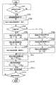
图3是表示现有图像编码装置100的整体控制部140及位速率控制部110的处理流程的流程图。 FIG. 3 is a flowchart showing the processing flow of the
最初,若由位速率控制部110接收发生比特数Nn131(S1401),则整体控制部140判断下一编码对象帧是否是帧群的开头(S1402)。此时,在下一帧是帧群的开头帧的情况下(S1402:是),位速率控制部110初始化可分配比特数Na、分配对象时间Ta及分配对象帧数Nt(S1405-1407)。这里,“NA”是分配给帧群单位的比特数的初始值。“TA”是帧群单位整体的期间。“Rf”是本图像编码装置100的编码帧速率。 First, when the number of generated bits Nn131 is received by the bit rate control unit 110 (S1401), the
另一方面,在下一帧不是帧群的开头帧的情况下(S1402:否),位速率控制部110更新可分配比特数Na及分配对象时间Ta(S1403-S1404)。 On the other hand, when the next frame is not the first frame of the frame group (S1402: No), the bit
接着,位速率控制部110根据可分配比特数Na和分配对象帧数Nt,算出分配比特数Nb(S1408),更新(减少)分配对象帧数Nt(S1409)。 Next, the bit
之后,位速率控制部110判断是否有必要对编码帧进行抽取,在必需抽取的情况下,将该情况通知整体控制部140(S1410:是)。另一方面,在不必需抽取的情况下,(S1410:否),算出量化幅度,输出到量化部106(S1411)。 Thereafter, the bit
整体控制部140及位速率控制部110重复以上处理,直到编码处理结束 (S1401-1412)。 The
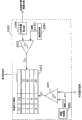
图4是表示现有位速率控制部110中分配比特数Nb的算出方法的具体例的图。此时,为了方便,设发生比特数Nn131与分配比特数Nb一致。 FIG. 4 is a diagram showing a specific example of a calculation method of the number Nb of allocated bits in the conventional bit
在图4的实例中,以15[fps]的帧速率对以30[fps]输入的图像信号数据(被编码帧信号101)进行编码,原则上每秒生成由15帧构成的帧群。在该实例中,用[输入图像帧序号1701]来表示输入的被编码帧信号101,用[帧群帧序号1702]来表示编码帧信号121。在图4中,帧群帧序号1702及发生比特数Nn131的栏变为[×]表示,对对应的输入图像帧序号1701的帧不进行编码,进行[抽取]。 In the example of FIG. 4 , image signal data (encoded frame signal 101 ) input at 30 [fps] is encoded at a frame rate of 15 [fps], and in principle, a frame group consisting of 15 frames is generated per second. In this example, the input coded
并且,图4中,由于已分配给4个帧的比特数共计1180比特,剩余帧数为[11],所以对于例如输入图像帧序号[9](即帧群帧序号[5])的发生比特数Nn变为((3600一1180)/11=220比特)。 And, in Fig. 4, since the number of bits that has been allocated to 4 frames is 1180 bits in total, and the number of remaining frames is [11], so for example, for the occurrence of the input image frame number [9] (that is, the frame group frame number [5]) The number of bits Nn becomes ((3600−1180)/11=220 bits). the
另一方面,因为[抽取]输入图像帧序号[11],由于已分配的比特数共计1400比特,剩余帧数为[9],所以对于输入图像帧序号[13](即帧群帧序号[6])的发生比特数在舍去小数点以下后,变为((3600-1400)/9=244比特)。 On the other hand, because of [extracting] the input image frame number [11], the number of allocated bits is 1400 bits in total, and the remaining frame number is [9]. Therefore, for the input image frame number [13] (that is, the frame group frame number [ 6]) The number of generated bits becomes ((3600-1400)/9=244 bits) after the decimal point is rounded off. the
另外,图4中对应于输入图像帧序号[29]的帧群帧序号1702栏中记载的“(14)”是在输入图像帧序号1701为[13]的时刻、最后帧群帧序号1702的预测值。 In addition, "(14)" recorded in the frame group frame number 1702 column corresponding to the input image frame number [29] in FIG. Predictive value. the
如上所述,通过现有的图像编码装置110向下一编码对象的帧分配比特。 As described above, the conventional
但是,在上述现有技术中使用可变位速率的图像编码装置100中,在编码困难(复杂)的帧连续的情况下,即使将量化幅度变为大的值,伴随编码的发生比特数也变多(此时,位速率的值变大)。此时,为了将规定时间长度(1个帧群)中的发生比特数保持为恒定,则对编码困难的帧连续的在后帧分配的比特数变少。因此,必需对在后帧增大量化幅度来进行编码,存在这些帧的画质极端恶化的第1问题(作为此时的现象,位速率变为明显小的值)。 However, in the
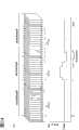
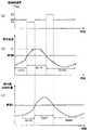
图5是说明上述现有技术的第1问题的图。在图5中,将从帧1601至帧1602的15个帧定义为帧群,向每个帧群(如上述图4中所示)分配3600[比 特]来作为目标值。此时,从时刻t1开始编码困难的画面连续,向这些帧的编码分配多的比特的情况下,因为分配给帧群后半的比特数变少,所以必需增大量化幅度(与此同时,位速率变小),但在将量化幅度设为大的值的情况下,画质极端恶化。在图5中,在[t3-t4]之间,量化幅度特别大,可推测与此同时,产生画质恶化。 FIG. 5 is a diagram explaining the first problem of the above-mentioned prior art. In FIG. 5, 15 frames from
并且,分配的比特数变得更加少,若必需在帧群途中变化帧速率(即,必需抽取帧)的情况下,则尽管帧速率变化,但由于分配给1个帧的比特数根据当初的帧速率来决定,所以尽管帧速率降低,但不能多分配比特数,并且,必需降低位速率,或稀疏量化幅度,存在画质进一步恶化的第2问题。 In addition, the number of allocated bits becomes even smaller, and if it is necessary to change the frame rate in the middle of a frame group (that is, to extract a frame), the number of bits allocated to one frame depends on the original number of bits despite the frame rate change. The frame rate is determined by the frame rate. Therefore, although the frame rate is lowered, the number of bits cannot be allocated more. In addition, the bit rate must be lowered, or the quantization width must be reduced, and there is a second problem of further deterioration of the image quality. the
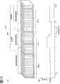
图6是说明上述现有技术的第2问题的图。在图6的实例中,编码困难的画面连续,因为向这些帧的编码分配多的比特,所以缓慢降低帧速率的结果是帧间隔拉大,从而变为动作不灵活的图像,显示作为图像的质量恶化的状态。 FIG. 6 is a diagram illustrating a second problem of the above-mentioned prior art. In the example of FIG. 6, the difficult-to-encode frames are consecutive, and since many bits are allocated to the encoding of these frames, the result of gradually reducing the frame rate is that the interval between frames is widened, resulting in an image with slow motion, and the display as an image A state of deteriorating quality. the
发明内容Contents of the invention
鉴于上述课题,本发明的目的在于提供一种图像编码装置及其方法,即使在编码困难的画面(scene)连续的情况下,也可防止分配给剩余帧的比特数极端不足导致的画质恶化,同时,还考虑了编码帧的比特变化,可进行高画质图像的编码。 In view of the above-mentioned problems, an object of the present invention is to provide an image coding apparatus and method thereof capable of preventing deterioration of image quality caused by extremely insufficient number of bits allocated to remaining frames even when difficult-to-code scenes (scenes) continue. , at the same time, the bit change of the coded frame is also considered, and the high-quality image can be coded. the
为了实现上述目的,本发明的图像编码装置,对以帧单位依次输入的图像信号进行编码,其特征在于:具备:编码单元,对上述每个帧量化上述图像信号的频率分量,根据上述量化的结果进行编码;发送缓冲器,保持由上述编码单元编码的编码数据,每次以一定量向外部输出保持的上述编码数据; In order to achieve the above object, the image encoding device of the present invention encodes an image signal sequentially input in frame units, and is characterized in that it includes: an encoding unit that quantizes the frequency components of the image signal for each frame, and based on the quantized The result is encoded; the sending buffer keeps the encoded data encoded by the above-mentioned encoding unit, and outputs the above-mentioned encoded data kept to the outside with a certain amount each time;
量化幅度计算单元,根据与未输出而原样残留在上述发送缓冲器内的编码数据的数据量对应的预测系数、以及当前量化幅度的预测值,计算后续编码的帧的量化幅度;帧速率计算单元,根据计算的上述量化幅度,计算后续编码的帧的编码帧速率;和输入控制单元,根据当前帧速率和由上述帧速率计算单元计算的上述编码帧速率,控制输入至上述编码单元的上述图像信号的取舍, 上述编码单元以后续编码的帧的上述量化幅度来量化输入的上述图像信号。所述的图像编码装置,其特征在于:若通过进行上述的编码而发生的编码量超过规定量,则上述量化幅度计算单元使后续编码的帧的上述量化幅度增大。 The quantization width calculation unit calculates the quantization width of the subsequent encoded frame based on the prediction coefficient corresponding to the data amount of the encoded data that is not output but remains as it is in the above-mentioned transmission buffer and the predicted value of the current quantization width; the frame rate calculation unit , calculating the encoding frame rate of the subsequent encoded frame according to the calculated quantization range; and an input control unit, controlling the input of the above-mentioned image to the above-mentioned encoding unit according to the current frame rate and the above-mentioned encoding frame rate calculated by the above-mentioned frame rate calculation unit For signal selection, the encoding unit quantizes the input image signal with the quantization amplitude of the subsequent encoded frame. In the image coding apparatus described above, the quantization width calculation unit increases the quantization width of a frame to be coded subsequently when the coding amount generated by performing the coding exceeds a predetermined amount. the
所述的图像编码装置,其特征在于:上述量化幅度计算单元具备:比较部,比较通过进行上述的编码而发生的编码量和规定阈值的大小;乘法部,上述比较的结果,若通过进行上述的编码而发生的编码量超过上述阈值,则在对紧前面的输入帧被计算了的上述量化幅度上乘以比1大的规定系数;和量化幅度决定部,将上述乘法的结果作为后续编码的帧的量化幅度的预测值,将规定值范围中最接近上述预测值的值决定为后续编码的帧的量化幅度。 The above-mentioned image encoding device is characterized in that: the quantization width calculation unit includes: a comparison unit that compares the amount of code generated by performing the above-mentioned encoding with the size of a predetermined threshold; If the amount of codes generated by encoding exceeds the above-mentioned threshold value, the above-mentioned quantization width calculated for the immediately preceding input frame is multiplied by a predetermined coefficient greater than 1; As for the predicted value of the quantization width of a frame, the value closest to the predicted value within a predetermined value range is determined as the quantization width of a frame to be coded subsequently. the
所述的图像编码装置,其特征在于:若通过进行上述的编码而发生的编码量小于规定量,则上述量化幅度计算单元还进行计算,以使后续编码的帧的上述量化幅度变小。 In the image encoding device described above, the quantization width calculation unit further calculates to reduce the quantization width of subsequent encoded frames if the amount of encoding generated by the encoding is smaller than a predetermined amount. the
所述的图像编码装置,其特征在于:上述比较的结果,在通过进行上述的编码而发生的编码量小于上述阈值的情况下,上述乘法部还在对紧前面的输入帧被计算了的上述量化幅度上乘以比1小的规定系数。 In the above-mentioned image encoding device, when the result of the comparison shows that the amount of codes generated by performing the encoding is smaller than the threshold value, the multiplication unit is further calculated for the immediately preceding input frame. The quantization width is multiplied by a predetermined coefficient smaller than 1. the
所述的图像编码装置,其特征在于:上述量化幅度计算单元还具备:系数表保持部,事先保持使未输出而原样残留在上述发送缓冲器内的编码数据的数据量对应于预测系数进行表示的系数表;和第2乘法部,根据上述系数表,在对紧前面的输入帧被计算了的上述量化幅度上乘以对应于上述发生的编码量的预测系数, In the image encoding device described above, the quantization width calculation unit further includes: a coefficient table holding unit that holds and represents in advance the data amount of the encoded data that remains in the transmission buffer without being output, in correspondence with prediction coefficients. The coefficient table; and the second multiplication unit, based on the coefficient table, multiplies the above-mentioned quantization width calculated for the immediately preceding input frame by the prediction coefficient corresponding to the above-mentioned generated encoding amount,
上述量化幅度决定部将上述第2乘法部的乘法结果作为后续编码的帧的量化幅度的预测值,决定后续编码的帧的量化幅度。 The quantization width determination unit determines the quantization width of the subsequent encoding frame using the multiplication result of the second multiplication unit as a predicted value of the quantization width of the subsequent encoding frame. the
所述的图像编码装置,其特征在于:若后续编码的帧的上述量化幅度的预测值超过指定的阈值,则上述帧速率计算单元增大后续编码的帧的编码帧速率。 The image encoding device is characterized in that if the predicted value of the quantization width of the subsequently encoded frame exceeds a specified threshold, the frame rate calculating unit increases the encoding frame rate of the subsequently encoded frame. the
所述的图像编码装置,其特征在于:若后续编码的帧的上述量化幅度的预测值超过上述指定的阈值,则上述帧速率计算单元在当前编码帧速率上乘以比1大的规定系数,并设为后续编码的帧的编码帧速率。 The above-mentioned image coding device is characterized in that: if the predicted value of the above-mentioned quantization width of the subsequent coded frame exceeds the above-mentioned specified threshold value, the above-mentioned frame rate calculation unit multiplies the current coded frame rate by a predetermined coefficient greater than 1, and Sets the encoding frame rate for subsequent encoded frames. the
所述的图像编码装置,其特征在于:若后续编码的帧的上述量化幅度的预测值小于上述指定的阈值,则上述帧速率计算单元减小后续编码的帧的编码帧速率。 The image encoding device is characterized in that: if the predicted value of the quantization width of the subsequently encoded frame is smaller than the specified threshold, the frame rate calculation unit reduces the encoding frame rate of the subsequently encoded frame. the
所述的图像编码装置,其特征在于:若后续编码的帧的上述量化幅度的预测值小于上述指定的阈值,则上述帧速率计算单元在当前编码帧速率上乘以比1小的规定系数,并设为后续编码的帧的编码帧速率。 The above-mentioned image coding device is characterized in that: if the predicted value of the above-mentioned quantization range of the subsequent coded frame is smaller than the above-mentioned specified threshold value, the above-mentioned frame rate calculation unit multiplies the current coded frame rate by a predetermined coefficient smaller than 1, and Sets the encoding frame rate for subsequent encoded frames. the
所述的图像编码装置,其特征在于:上述帧速率计算单元,当决定的上述量化幅度超过规定阈值,则增大后续编码的帧的编码帧速率,当小于上述阈值,则减小后续编码的帧的编码帧速率。 The image encoding device is characterized in that: the frame rate calculation unit, when the determined quantization range exceeds a predetermined threshold, increases the encoding frame rate of subsequent encoded frames; The frame rate at which frames are encoded. the
所述的图像编码装置,其特征在于:上述帧速率计算单元具备对已决定的上述量化幅度的平均值进行计算的量化幅度平均部, The image encoding device described above is characterized in that the frame rate calculation unit includes a quantization width averaging unit that calculates the determined average value of the quantization width,
上述帧速率计算单元,当后续编码的帧的上述量化幅度的平均值超过规定阈值,则增大后续编码的帧的编码帧速率,当小于上述阈值,则减小后续编码的帧的编码帧速率。 The above-mentioned frame rate calculation unit, when the average value of the above-mentioned quantization range of the subsequent encoded frame exceeds a predetermined threshold, then increase the encoding frame rate of the subsequent encoded frame, and when it is less than the above-mentioned threshold, then reduce the encoding frame rate of the subsequent encoded frame . the
所述的图像编码装置,其特征在于:在上述发送缓冲器的空闲容量小于规定阈值的情况下,上述帧速率计算单元在当前帧速率上乘以比1小的规定系数,并重新设为上述计算的编码帧速率。 The above-mentioned image encoding device is characterized in that, when the free capacity of the transmission buffer is smaller than a predetermined threshold, the frame rate calculation unit multiplies the current frame rate by a predetermined coefficient smaller than 1, and resets the calculation to The encoded frame rate. the
所述的图像编码装置,其特征在于:在上述发送缓冲器的空闲容量大于规定阈值的情况下,上述帧速率计算单元在当前帧速率上乘以比1大的规定系数,并重新设为上述计算的编码帧速率。 The above-mentioned image encoding device is characterized in that, when the free capacity of the transmission buffer is greater than a predetermined threshold, the frame rate calculation unit multiplies the current frame rate by a predetermined coefficient greater than 1, and resets the calculation to encoding frame rate. the
一种图像编码装置,对以帧单位依次输入的图像信号进行编码,其特征在于:具备:编码单元,对上述每个帧量化上述图像信号的频率分量,根据上述量化的结果进行编码;发送缓冲器,保持由上述编码单元编码的编码数据,每次以一定量向外部输出保持的上述编码数据;量化幅度计算单元,根据与未输出而原样残留在上述发送缓冲器内的编码数据的数据量对应的预测系数、以及当前量化幅度的预测值,计算后续编码的帧的量化幅度;帧速率计算单元,根据计算的上述量化幅度,计算后续编码的帧的编码帧速率;和 An image encoding device, which encodes image signals sequentially input in frame units, is characterized in that: an encoding unit quantizes the frequency components of the image signal for each frame, and performs encoding based on the result of the quantization; a transmission buffer The device holds the encoded data encoded by the encoding unit, and outputs the retained encoded data to the outside in a certain amount each time; The corresponding prediction coefficient and the predicted value of the current quantization range calculate the quantization range of the subsequent encoded frame; the frame rate calculation unit calculates the encoding frame rate of the subsequent encoded frame according to the calculated above-mentioned quantization range; and
输入控制单元,上述输入控制单元具备帧速率平均部,算出作为上述帧 速率计算单元的计算结果的编码帧速率的平均值, An input control unit, wherein the input control unit has a frame rate averaging unit, and calculates an average value of the encoding frame rate as a calculation result of the frame rate calculation unit,
上述输入控制单元根据由当前帧速率和上述帧速率平均部算出的上述平均值,控制上述输入的图像信号的取舍。 The input control unit controls the selection of the input image signal based on the current frame rate and the average value calculated by the frame rate averaging unit. the
一种图像编码方法,对帧单位的图像信号进行编码,其特征在于包含:编码步骤,对上述每个帧量化上述图像信号的频率分量,根据上述量化的结果进行编码;输出步骤,将由上述编码步骤编码的编码数据存储至发送缓冲器,每次以一定量向外部输出存储的上述编码数据;量化幅度计算步骤,根据与未输出而原样残留在上述发送缓冲器内的编码数据的数据量对应的预测系数、以及当前量化幅度的预测值,计算后续应编码的帧的量化幅度;帧速率计算步骤,根据计算的上述量化幅度,计算后续编码的帧的编码帧速率;和输入控制步骤,根据当前帧速率和由上述帧速率计算步骤计算的上述编码帧速率,控制上述编码步骤中输入的上述图像信号的取舍, An image encoding method, which encodes an image signal in a frame unit, is characterized in that it includes: an encoding step, quantizing the frequency component of the above-mentioned image signal for each frame, and encoding according to the result of the above-mentioned quantization; The coded data encoded in the step code is stored in the transmission buffer, and the above-mentioned coded data stored is output to the outside by a certain amount each time; the quantization width calculation step is based on the data volume corresponding to the coded data that has not been output but remains in the above-mentioned transmission buffer. The prediction coefficient and the predicted value of the current quantization range calculate the quantization range of the subsequent frame to be encoded; the frame rate calculation step calculates the encoding frame rate of the subsequent encoded frame according to the calculated above-mentioned quantization range; and the input control step, according to The current frame rate and the above-mentioned encoding frame rate calculated by the above-mentioned frame rate calculation step control the trade-off of the above-mentioned image signal input in the above-mentioned encoding step,
上述编码步骤通过后续编码的帧的上述量化幅度来量化输入的上述图像信号。 The encoding step quantizes the input image signal by the quantization magnitude of the subsequently encoded frame. the
本发明的图像编码装置是对以帧单位依次输入的图像信号进行编码的图像编码装置,其中具备:帧速率接受单元,接受表示进行上述编码的周期的帧速率;总比特数确定单元,确定作为整体可向由多个帧构成的帧群分配的总比特数;帧数确定单元,根据上述接受的帧速率和已编码帧的帧数,确定上述帧群中还未编码的帧的帧数;目标比特数算出单元,根据上述确定的总比特数和上述确定的帧数,算出分配给后续编码帧的比特数的目标值;平均值算出单元,随着上述帧群中的帧的编码,算出分配确定的比特数的平均值;运算单元,根据上述目标值和上述平均值,对上述算出的上述比特数的目标值与上述比特数的平均值进行比较运算,确定新的比特数的目标值;以及量化幅度导出单元,使用由上述运算单元确定的比特数的目标值,导出涉及后续编码的帧的量化幅度;和编码单元,根据上述导出的量化幅度来进行量化,根据该量化来进行编码。 The image encoding device of the present invention is an image encoding device that encodes image signals sequentially input in frame units, and includes: a frame rate accepting unit that accepts a frame rate indicating a cycle for performing the above-mentioned encoding; a total bit number determining unit that determines the number of bits as The total number of bits that can be allocated to a frame group composed of a plurality of frames as a whole; the frame number determination unit determines the number of frames of unencoded frames in the above-mentioned frame group according to the above-mentioned accepted frame rate and the number of frames of encoded frames; The target number of bits calculation unit calculates the target value of the number of bits allocated to subsequent encoded frames according to the above-mentioned determined total number of bits and the above-mentioned determined number of frames; the average value calculation unit, along with the encoding of the frames in the above-mentioned frame group, calculates Assigning the average value of the determined number of bits; the computing unit, according to the above-mentioned target value and the above-mentioned average value, compares the calculated target value of the above-mentioned number of bits with the average value of the above-mentioned number of bits, and determines a new target value of the number of bits and a quantization width derivation unit, using the target value of the number of bits determined by the above-mentioned operation unit, to derive the quantization width of the frame involved in the subsequent encoding; and the coding unit, performing quantization according to the quantization width derived above, and encoding according to the quantization . the
由此,根据分配给帧群整体的总比特数和已分配完的比特数,计算应分配给后续编码帧的比特数,使对帧群而言变为恒定的位速率,所以避免分配 的比特数局部偏差的情况于未然,可平均分配比特,最终可防止极端的画质恶化。而且,根据基于接受的帧速率算出的还未编码的帧数、和帧群中可分配的比特数,决定应分配给后续编码帧的比特数,所以可进行遵循帧速率变化的编码。 Therefore, according to the total number of bits allocated to the frame group as a whole and the number of bits that have been allocated, the number of bits that should be allocated to the subsequent encoding frame is calculated, so that the bit rate becomes constant for the frame group, so the allocated bits are avoided Evenly distributes bits to prevent local deviations in data, and ultimately prevents extreme image quality degradation. Furthermore, since the number of bits to be allocated to the subsequent encoding frame is determined based on the number of unencoded frames calculated based on the accepted frame rate and the number of bits that can be allocated in the frame group, encoding that follows frame rate changes can be performed. the
并且,为了实现上述目的,本发明的图像编码方法是对以帧单位依次输入的图像信号进行编码的图像编码装置,其特征在于:包含:帧速率接受步骤,接受表示进行上述编码的周期的帧速率;总比特数确定步骤,确定整体上可向由多个帧构成的帧群分配的总比特数;帧数确定步骤,根据上述接受的帧速率和已编码帧的帧数,确定上述帧群中还未编码的帧的帧数;目标比特数算出步骤,根据上述确定的总比特数和上述确定的帧数,算出分配给后续编码帧的比特数的目标值;平均值算出步骤,随着上述帧群中的帧的编码,算出分配确定的比特数的平均值;运算步骤,根据上述目标值和上述平均值,对上述算出的上述比特数的目标值与上述比特数的平均值进行比较运算,确定新的比特数的目标值;量化幅度导出步骤,使用由上述运算单元确定的比特数的目标值,导出涉及后续编码的帧的量化幅度;以及编码步骤,根据上述导出的量化幅度来进行量化,根据该量化来进行编码。 Furthermore, in order to achieve the above object, the image encoding method of the present invention is an image encoding apparatus for encoding image signals sequentially input in frame units, and is characterized in that it includes: a frame rate accepting step for accepting a frame indicating a cycle for performing the above encoding. rate; a step of determining the total number of bits to determine the total number of bits that can be allocated to a frame group composed of a plurality of frames as a whole; a step of determining the number of frames based on the above-mentioned accepted frame rate and the number of frames of the encoded frames, determining the above-mentioned frame group The frame number of the frame that has not yet been coded in; The target number of bits calculates the step, according to the total number of bits determined above-mentioned and the number of frames determined above, calculates the target value of the number of bits allocated to subsequent encoded frames; The average value calculates the step, along with In the encoding of the frames in the frame group, an average value of the assigned number of bits is calculated; an operation step, based on the above-mentioned target value and the above-mentioned average value, the calculated target value of the above-mentioned number of bits is compared with the average value of the above-mentioned number of bits operation, to determine the target value of the new number of bits; the quantization width deriving step, using the target value of the number of bits determined by the above-mentioned operation unit, to derive the quantization width of the frames involved in the subsequent encoding; and the encoding step, based on the quantization width derived above. Quantization is performed, and encoding is performed based on the quantization. the
由此,在确保在规定时间长度内观测情况下的位速率恒定的同时,在缓冲器中有足够空间的情况下,通过以低的量化幅度来编码,可比以前高画质地编码,且抑制移动到复杂画面情况下的帧速率的急剧下降(不编码而跳过多个帧),与以前相比,可进行动作平滑的编码。 Thus, while ensuring a constant bit rate in the case of observation over a predetermined period of time, if there is enough space in the buffer, by encoding with a low quantization width, it is possible to encode with higher image quality than before, and suppress In the case of moving to a complex screen, the frame rate drops sharply (a number of frames are skipped without coding), and smoother motion coding is possible than before. the
另外,为了实现上述目的,本发明可实现为将上述图像编码装置的装置特征单元设为步骤的图像编码方法,或实现为包含这些步骤的程序。另外,该程序不仅存储在图像编码装置具备的ROM等中,也可经CD-ROM等记录媒体或通信网络等传输媒体来进行流通。 In addition, in order to achieve the above object, the present invention can be implemented as an image encoding method using the device characteristic elements of the above-mentioned image encoding device as steps, or as a program including these steps. In addition, the program is not only stored in a ROM or the like included in the image encoding device, but may also be distributed via a recording medium such as a CD-ROM or a transmission medium such as a communication network. the
附图说明Description of drawings
图1是表示使用现有可变位速率的图像编码装置的功能结构框图。 FIG. 1 is a block diagram showing the functional structure of a conventional image coding apparatus using a variable bit rate. the
图2是表示现有图像编码装置中的位速率控制部的功能结构框图。 FIG. 2 is a block diagram showing a functional configuration of a bit rate control unit in a conventional image encoding device. the
图3是表示现有图像编码装置的整体控制部及位速率控制部中处理的流 FIG. 3 is a diagram showing the flow of processing in an overall control unit and a bit rate control unit of a conventional image encoding device.
图4是表示现有位速率控制部中分配比特数的算出方法的具体实例的图。 FIG. 4 is a diagram showing a specific example of a method of calculating the number of allocated bits in a conventional bit rate control unit. the
图5(a)是说明现有技术的第1问题用的帧群的结构例。 Fig. 5(a) is an example of the structure of a frame group for explaining the first problem of the prior art. the
图5(b)是说明现有技术的第1问题用的位速率的一例。 FIG. 5(b) is an example of a bit rate for explaining the first problem of the prior art. the
图6(a)是说明现有技术的第2问题用的帧群的结构例。 Fig. 6(a) is an example of the structure of a frame group for explaining the second problem of the prior art. the
图6(b)是说明现有技术的第2问题用的位速率的一例。 FIG. 6(b) is an example of a bit rate for explaining the second problem of the prior art. the
图7是表示实施例1中图像编码装置的功能结构的框图。 FIG. 7 is a block diagram showing the functional structure of the image coding apparatus in the first embodiment. the
图8是表示图7中位速率控制部的详细功能结构的框图。 FIG. 8 is a block diagram showing a detailed functional configuration of a bit rate control unit in FIG. 7 . the
图9是表示一般图像编码中的不同图像类型的发生比特数特征的图。 Fig. 9 is a diagram showing the characteristics of the number of generated bits for different picture types in general picture coding. the
图10是图9中定义的帧群的具体例。 FIG. 10 is a specific example of the frame group defined in FIG. 9 . the
图11是图9中定义的帧群的变形例。 FIG. 11 is a modified example of the frame group defined in FIG. 9 . the
图12(a)是说明如上述图11那样由两个帧组构成帧群所产生的效果的图。 FIG. 12( a ) is a diagram explaining the effect of forming a frame group from two frame groups as in FIG. 11 described above. the
图12(b)是说明如上述图11那样由两个帧组构成帧群、且编码帧速率变化情况下的效果的图。 Fig. 12(b) is a diagram illustrating the effect when a frame group is composed of two frame groups as in Fig. 11 described above and the encoding frame rate is changed. the
图13是表示实施例1中图像编码装置的整体控制部及位速率控制部中的处理流程的流程图。 13 is a flowchart showing the flow of processing in the overall control unit and the bit rate control unit of the image encoding device in the first embodiment. the
图14(a)是表示使用实施例1的图像编码装置来执行编码的情况下的帧群的构成例的图。 Fig. 14(a) is a diagram showing a configuration example of a frame group when encoding is performed using the image encoding device of the first embodiment. the
图14(b)是表示使用实施例1的图像编码装置来执行编码的情况下的位速率变化的一例。 Fig. 14(b) shows an example of bit rate change when encoding is performed using the image encoding device of the first embodiment. the
图15(a)是表示由两个帧组来构成1个帧群的情况下各帧的状态的一例。 FIG. 15( a ) shows an example of the state of each frame when one frame group is constituted by two frame groups. the
图15(b)是表示由两个帧组来构成1个帧群的情况下位速率变动状态的一例。 FIG. 15( b ) shows an example of a bit rate fluctuation state when one frame group is constituted by two frame groups. the
图16(a)是表示由两个帧组来构成1个帧群、并且编码的帧速率变化的情况下各帧的状态的一例。 FIG. 16( a ) shows an example of the state of each frame when one frame group is constituted by two frame groups and the encoding frame rate changes. the
图16(b)是表示由两个帧组来构成1个帧群、并且编码的帧速率变化的情况下位速率变动状态的一例。 FIG. 16( b ) shows an example of a bit rate fluctuation state when one frame group is constituted by two frame groups and the frame rate of encoding changes. the
图17是表示运算部中比特数算出方法的具体例的图。 FIG. 17 is a diagram showing a specific example of a method of calculating the number of bits in the calculation unit. the
图18是表示未设置在图7中帧抽取部、从其它部件获得帧速率值Rf的值来构成的图像编码装置的功能结构的一部分的框图。 FIG. 18 is a block diagram showing a part of the functional structure of an image encoding device configured by obtaining a frame rate value Rf from other components without providing a frame extraction unit in FIG. 7 . the
图19是表示根据实施例2的图像编码装置的功能结构的框图。 FIG. 19 is a block diagram showing the functional structure of an image encoding device according to
图20是表示图19中速率控制部的详细功能结构的框图。 FIG. 20 is a block diagram showing a detailed functional configuration of a rate control unit in FIG. 19 . the
图21是说明图20中的量化幅度(步骤)预测部的功能用框图。 FIG. 21 is a block diagram for explaining the function of a quantization width (step) prediction unit in FIG. 20 . the
图22是说明图20中帧速率计算部的功能用框图。 Fig. 22 is a block diagram for explaining the function of the frame rate calculation unit in Fig. 20 . the
图23是表示图22中帧速率计算部的各输入信号和输出信号的图。 FIG. 23 is a diagram showing input signals and output signals of the frame rate calculation unit in FIG. 22 . the
图24是说明图20中帧数计算部的动作的图。 FIG. 24 is a diagram explaining the operation of the frame number calculation unit in FIG. 20 . the
图25是表示图像编码装置的输入图像信号与被编码帧的图。 Fig. 25 is a diagram showing an input video signal and frames to be coded by the video coding device. the
图26是表示变形例的帧速率控制部的功能结构框图。 FIG. 26 is a block diagram showing a functional configuration of a frame rate control unit according to a modified example. the
图27是表示图26中的帧速率计算部的各输入信号和输出信号的图。 FIG. 27 is a diagram showing input signals and output signals of a frame rate calculation unit in FIG. 26 . the
图28是表示变形例的帧速率控制部的功能结构框图。 FIG. 28 is a block diagram showing a functional configuration of a frame rate control unit in a modified example. the
图29是表示图28中平均量化幅度计算部的结构框图。 Fig. 29 is a block diagram showing the structure of an average quantization width calculation unit in Fig. 28 . the
图30是说明图28中帧速率计算部功能用框图。 Fig. 30 is a block diagram for explaining the function of the frame rate calculation unit in Fig. 28 . the
图31是表示图28中的帧速率计算部的各输入信号和输出信号的图。 FIG. 31 is a diagram showing input signals and output signals of a frame rate calculation unit in FIG. 28 . the
图32是表示变形例的帧速率控制部的功能结构框图。 FIG. 32 is a block diagram showing a functional configuration of a frame rate control unit according to a modified example. the
图33是说明图32中的帧速率计算部和帧速率存储器的功能用框图。 Fig. 33 is a block diagram for explaining the functions of the frame rate calculation unit and the frame rate memory in Fig. 32 . the
图34是表示图32中的帧速率计算部的各输入信号和输出信号的图。 FIG. 34 is a diagram showing input signals and output signals of a frame rate calculation unit in FIG. 32 . the
图35是表示实施例3中的图像编码装置的功能结构的框图。 Fig. 35 is a block diagram showing the functional configuration of the image encoding device in the third embodiment. the
图36是表示图35图像编码装置中帧速率控制部的功能结构的框图。 Fig. 36 is a block diagram showing the functional configuration of a frame rate control unit in the image encoding device of Fig. 35 . the
图37是说明存储通过一般的计算机系统来实现实施例1-3中的图像编码装置用的程序的存储媒体的图。 Fig. 37 is a diagram illustrating a storage medium storing a program for realizing the image encoding device in Embodiments 1-3 by a general computer system. the
具体实施方式Detailed ways
下面,参照附图来详细说明根据本发明的实施例。在以下的说明中,对与现有技术共同的结构标以相同符号,省略其说明。 Hereinafter, embodiments according to the present invention will be described in detail with reference to the drawings. In the following description, the same reference numerals are assigned to the same configurations as those in the prior art, and the description thereof will be omitted. the
(实施例1) (Example 1)
图7是表示根据实施例1的图像编码装置10的功能结构的框图。图像编码装置10通过将在规定时间长度(例如1秒)观测情况下的位速率保持为恒定,并抑制局部的位速率变动,可进行更高质量的图像再现用的编码。 FIG. 7 is a block diagram showing the functional configuration of the
图像编码装置10由帧存储器102、动作检测部103、动作补偿部104、正交变换部105、量化部106、可变长编码部107、逆量化部108、逆正交变换部109、帧抽取部(间引部)20、速率控制部30及整体控制部40构成。 The
帧抽取部20对在一定周期内输入的被编码帧信号101决定该帧的编码/不编码,同时,将该时刻的帧速率值Rf21通知给速率控制部30。 The
速率控制部30根据从可变长编码部107接收的发生比特数和从帧抽取部20接收通知的帧速率值Rf21,决定后续帧的编码中的量化幅度(或量化参数),发送给量化部106。 The
整体控制部40是例如具备ROM或RAM等的微型计算机,进行图像编码装置10整体的控制。更详细地说,整体控制部40根据控制信号(图7的整体控制部40中的虚线表示控制信号线),进行各部处理定时的控制。并且,整体控制部40进行在一定周期中输入的被编码帧信号101的图像种类的识别(I帧、B帧及P帧的识别),将识别结果通知速率控制部30。 The
图8是表示图7中速率控制部30的详细功能结构的框图。速率控制部30由帧群目标比特数导出部31、下一帧目标比特数导出部32、平均帧比特数导出部33、运算部34、量化幅度(步骤)导出部35及存储部36构成。 FIG. 8 is a block diagram showing a detailed functional configuration of the
帧群目标比特数导出部31通过帧群单位,依次算出并更新可分配给剩余应编码的全部帧的总比特数的目标值。详细说明时,帧群目标比特数导出部31从可变长编码部107接收发生比特数Nn131,存储在存储部36中。并且,帧群目标比特数导出部31从存储部36中,读取可分配给从下一应编码帧到帧群的最后帧的总比特数,从该总比特数中减去上述发生比特数Nn131,将该值发送给下一帧目标比特数导出部32,同时存储在存储部36中。 The frame group target number of bits derivation
下一帧目标比特数导出部32根据从帧抽取部20接收的帧速率值Rf21及从帧群目标比特数导出部31接收的可分配总比特数,考虑剩余的应编码帧的 帧数,算出分配给下一帧的比特数目标值。 The next frame target number of bits derivation
平均帧比特数导出部33根据从帧抽取部20接收的帧速率值Rf21及存储在存储部36中的分配给过去帧的比特数,算出分配的比特数的平均值。 The average frame bit
运算部34算出向由平均帧比特数导出部33算出的比特数中乘以规定系数(例如0.8)后的比特数,将其与由下一帧目标比特数导出部32算出的比特数目标值相比,选择值大的一方的比特数。并且,运算部34将选择的比特数与事先设定的下限值相比,选择较大值的比特数(即选择不低于下限值的比特数),发送到量化幅度导出部35。上述规定系数不限于[0.8],也可是大于0小于1的其它值。 The
量化幅度导出部35导出量化幅度的值,使从运算部34接收到的比特数与发生比特数相等。 The quantization
存储部36存储作为编码从可变长编码部107接收到的各帧的结果的发生比特数Nn131。并且,存储部36还根据帧群目标比特数导出部31的控制来更新帧群目标比特数。 The
图9是表示图像编码中的不同图像类型的发生比特数的一般特征的图。如图9所示,通常,帧间编码(P图像或B图像)的帧(P或B帧)中的发生比特数Nn帧内编码(I图像)的帧(I帧210-250)中的发生比特数Nn少。因此,通过将从I帧到下一I帧定义为一个帧群,与根据其它标准来定义帧群的情况(例如与图像类型无关,以每15个帧来构成帧群的情况)相比,可减少各帧群中发生比特数的偏差。另外,在图9的实例中,为了方便,设各帧群的编码所需时间为TA,设为相同周期。 Fig. 9 is a diagram showing general characteristics of the number of generated bits for different picture types in picture coding. As shown in FIG. 9, in general, the number of occurrence bits Nn in a frame (P or B frame) of an inter-coded (P-picture or B-picture) in a frame (I-frame 210-250) of an intra-coded (I-picture) The number Nn of occurrence bits is small. Therefore, by defining one frame group from an I frame to the next I frame, compared with a case where a frame group is defined according to another standard (for example, a case where a frame group is constituted every 15 frames regardless of the image type), Variations in the number of bits occurring in each frame group can be reduced. In addition, in the example of FIG. 9, for the sake of convenience, the time required for encoding of each frame group is assumed to be TA, and the period is set to be the same. the
即使仅帧群的最初帧是上述I帧,帧群的最后帧是I帧,但也可得到减少各帧群中比特数偏差的效果。 Even if only the first frame of the frame group is the above-mentioned I frame and the last frame of the frame group is the I frame, the effect of reducing the deviation of the number of bits among the frame groups can be obtained. the
图10是表示上述图9中定义的帧群的具体例的图。如图10所示,设帧群310由从帧内编码(I)帧210到帧内编码(I)帧220紧前面帧的15个帧构成。同样,设帧群220或帧群230也分别由15个帧构成。此时,事先决定可分配给1个帧群的总比特数的初始值(例如3600[比特]等)。另外,帧群的定义方式不限于图10。 FIG. 10 is a diagram showing a specific example of the frame group defined in FIG. 9 above. As shown in FIG. 10 , the frame group 310 is assumed to be composed of 15 frames from the intra-coded (I) frame 210 to the frame immediately preceding the intra-coded (I) frame 220 . Similarly, it is assumed that the frame group 220 or the frame group 230 is also composed of 15 frames. At this time, an initial value (for example, 3600 [bits], etc.) of the total number of bits that can be allocated to one frame group is determined in advance. In addition, the definition method of the frame group is not limited to FIG. 10 . the
图11是上述图9中定义的帧群的变形例。如图11所示,也可将由相当于上述图10中的两个帧群310、320的第1帧组和第2帧组构成的帧的集合定义为1个帧群410。此时,设可分配给帧群410的总比特数的初始值为7200[比特](第1帧组及第2帧组分别为3600[比特])。 FIG. 11 is a modified example of the frame group defined in FIG. 9 above. As shown in FIG. 11 , a frame group 410 may be defined as a set of frames composed of a first frame group and a second frame group corresponding to the two frame groups 310 and 320 in FIG. 10 . At this time, the initial value of the total number of bits that can be allocated to the frame group 410 is 7200 [bits] (3600 [bits] for the first frame group and the second frame group, respectively). the
图12是说明上述图11那样由两个帧组构成帧群所产生的效果图。图12(a)中,即使在1个帧群中有难以编码的画面的情况下,因为可以决定包含下面第2帧组中的可分配比特数的下面被编码帧的分配比特数,所以可进一步缓和位速率的变化。例如,设作为初始值,在帧群410整体中分配1000比特,暂定向第1帧组分配500比特,向第2帧组分配500比特。之后,在实际编码中,可控制成即使对第1帧组使用700比特,但在后续帧群420中,作为初始值,在整体中分配800[比特](上一帧群410剩余的300[比特]+新的第2帧组500[比特])。 FIG. 12 is a diagram illustrating the effect of forming a frame group by two frame groups as shown in FIG. 11 above. In Fig. 12(a), even if there is a difficult-to-code picture in one frame group, the number of allocated bits of the following frame to be encoded including the number of allocated bits in the second frame group below can be determined, so it is possible to To further moderate bit rate changes. For example, as an initial value, 1000 bits are allocated to the entire frame group 410, 500 bits are temporarily allocated to the first frame group, and 500 bits are allocated to the second frame group. Thereafter, in actual encoding, even if 700 bits are used for the first frame group, 800 [bits] (the remaining 300 [bits] of the previous frame group 410 are allocated as an initial value in the
图12(b)中,即使是因为编码困难所以必需变更帧速率的情况下,也可通过与上述图12(a)一样的方法,避免位速率急剧变为小的值(即量化幅度急剧变大)。 In Fig. 12(b), even when it is necessary to change the frame rate because encoding is difficult, the same method as in Fig. 12(a) above can be used to prevent the bit rate from suddenly changing to a small value (that is, a sudden change in the quantization width). big). the
图13是表示图像编码装置10的整体控制部40及位速率控制部30中的处理流程的流程图。 FIG. 13 is a flowchart showing the flow of processing in the
首先,速率控制部30从可变长编码部107接收发生比特数Nn131(S701),从帧抽取部20接收帧速率值Rf21(S702)。 First, the
接着,整体控制部401识别后续帧是否是I帧(S703)。此时,在后续帧是I帧的情况下(S704:是),速率控制部30初始化可分配比特数Na、分配对象期间Ta及分配对象帧数Nt(S708-S710)。 Next, the overall control unit 401 identifies whether or not the subsequent frame is an I frame (S703). At this time, when the subsequent frame is an I frame (S704: Yes), the
另一方面,在后续帧不是I帧的情况下(S704:否),速率控制部30更新可分配比特数Na及分配对象帧数Nt(S705、S706)。另外,速率控制部30舍掉分配对象帧数Nt的小数点以后的值,对Nt进行整数化(S707)。 On the other hand, when the subsequent frame is not an I frame (S704: No), the
之后,速率控制部30根据可分配比特数Na及分配对象帧数Nt来算出分配比特数Nb(S711),更新分配对象期间Ta(S712)。此时,分配对象期间Ta在帧速率值Rf21的值相同的帧群途中变更的情况下也考虑进行更新。 Thereafter, the
由此,速率控制部30根据分配比特数Nb导出量化幅度,发送到可变长编码部107(S713)。 Thus, the
整体控制部40及速率控制部30重复以上处理,直到编码处理结束(S701-S714)。 The
图14是表示使用图像编码装置10来执行编码的情况下的位速率变化的一例。若观察图14所示位速率的变化,则由于运算部34的系数(例如0.8),与现有技术的情况(上述图5)相比,将可分配的比特数抑制得少,所以位速率变化有钝化倾向。并且,在图14中,算出量化幅度,使上述运算部34选择不低于下限值的比特数,编码后的比特数变为该比特数。并且,根据算出的量化幅度来执行编码,决定发生比特,所以即使对位速率也示出变为大于下限值的值的状态。 FIG. 14 shows an example of bit rate change when encoding is performed using the
图15是表示如上述图11所示,由两个帧组来构成1个帧群的情况下位速率变动状态的一例。如图15所示,示出在现有技术(上述图5)中,位速率的值明显小(即量化幅度明显大)的[t3-t4]中,可抑制位速率的帧小,抑制画质恶化,但第1帧组中使用多个比特数的影响出现于第2帧组的最初部分([t4-t6]中)(即,不能减小量化幅度,位速率值不变,仍小)的状态。 FIG. 15 shows an example of a bit rate fluctuation state when one frame group is constituted by two frame groups as shown in FIG. 11 above. As shown in Figure 15, it shows that in the prior art (above Figure 5), in [t3-t4] where the value of the bit rate is obviously small (that is, the quantization range is obviously large), the frame that can suppress the bit rate is small, and the quality deteriorates, but the effect of using multiple bit numbers in
图16是表示由两个帧组来构成1个帧群、并且在帧群途中编码的帧速率变化的情况下位速率变动状态的一例。在图16中,帧速率从15[fps]变化到7.5[fps],但位速率变化方式与上述图14的位速率一样(即在图16的情况下,因为以1/2量化幅度中进行编码发生2倍的比特数,所以在假设是作为位速率变为相同的情况,即使在该情况下也可在[t3-t4]中抑制画质恶化)。 FIG. 16 shows an example of a bit rate fluctuation state when one frame group is constituted by two frame groups and the frame rate of encoding changes during the frame group. In Fig. 16, the frame rate is changed from 15 [fps] to 7.5 [fps], but the bit rate is changed in the same way as the bit rate of Fig. 14 above (i.e. in the case of Fig. Encoding generates twice the number of bits, so assuming that the bit rate becomes the same, even in this case, image quality degradation can be suppressed in [t3-t4]). the
图17是表示上述图8的运算部34中比特数算出方法的具体例的图。在图17的实例中,由15[fps]的帧速率对以30[fps]输入的被编码帧信号101实施编码。即使在该实例中也与上述图6一样,用[输入图像帧序号1701]来表示输入的被编码帧信号101,用[帧群帧序号1102]来表示编码帧信号121。在图17中,帧群帧序号1102及发生比特数Nn131的栏为[×]表示, 对对应的输入图像帧序号1701的帧不进行编码而[抽取]。 FIG. 17 is a diagram showing a specific example of a method of calculating the number of bits in the
另外,在图17中,例如因为已分配的比特数合计为1180[比特],剩余帧数为[11],所以对输入图像帧序号[9](即帧群帧序号[5])的发生比特数目标值变为((3600-1180)/11=220[比特])。另外,算出平均帧比特数导出部33中过去帧的发生比特数的平均值(1180/4=295[比特]),运算部34向发生比特数的平均值乘以系数(例如0.8),将其与上述比特数的目标值相比较,选择值大的一方。结果,对帧群帧序号[5]的发生比特数变为236[比特]。 In addition, in Fig. 17, for example, because the total number of allocated bits is 1180 [bits], and the remaining number of frames is [11], the occurrence of the input image frame number [9] (that is, the frame group frame number [5]) The target value of the number of bits becomes ((3600-1180)/11=220 [bits]). In addition, the average value (1180/4=295 [bits]) of the number of generated bits in the past frame in the average frame bit
另一方面,因为对输入图像帧序号[11]的帧进行[抽取](因此,帧速率值Rf21变更为7.5[fps]),所以根据剩余帧数(因为以7.5[fps]来计算帧速率值Rf21)[5]来计算对输入图像帧序号[13](即帧群帧序号[6])的发生比特数。并且,因为对计算的值舍掉小数点以下的值,所以变为(3600-1416)/5=436[比特]。另外,算出平均帧比特数导出部33中过去帧的发生比特数的平均值(1416/5=383[比特]),运算部34向发生比特数的平均值乘以系数(例如0.8),将其与上述比特数的目标值相比较,选择值大的一方。结果,对输入图像帧序号[13]的发生比特数变为436[比特]。 On the other hand, since [extraction] is performed on the frame of the input image frame number [11] (therefore, the frame rate value Rf21 is changed to 7.5 [fps]), the frame rate is calculated based on the number of remaining frames (because 7.5 [fps] Value Rf21)[5] to calculate the number of occurrence bits for the input image frame number [13] (ie frame group frame number [6]). In addition, since values below the decimal point are dropped from the calculated value, it becomes (3600-1416)/5=436 [bits]. In addition, the average value (1416/5=383 [bits]) of the number of generated bits in the past frame in the average frame bit
若比较图17与上述现有技术图4中的帧群帧序号[5]及[6]的发生比特数Nn,则本图像编码装置10(即上述图17)中的发生比特数都变为大的值,因为可分配较多的比特数,所以与以前相比,可知可进行高品质的图像用编码。 Comparing FIG. 17 with the number of bits Nn of the frame group frame numbers [5] and [6] in the above prior art FIG. Since a large value can allocate a larger number of bits, it can be seen that high-quality image coding can be performed compared with conventional ones. the
另外,在对应于上述图17的输入图像帧序号[29]的帧群帧序号栏中记载两个数字,“(15)”是输入图像帧序号为[9]的时刻、帧速率为15[fps]情况下帧群帧序号1102的预测值,“(10)”是输入图像帧序号为[13]的时刻、帧速率为7.5[fps]情况下帧群帧序号1102的预测值。 In addition, two numbers are recorded in the column of the frame group frame number corresponding to the input image frame number [29] of the above-mentioned FIG. fps], the predicted value of the frame group frame number 1102, and "(10)" is the predicted value of the frame group frame number 1102 when the input image frame number is [13] and the frame rate is 7.5 [fps]. the
在上述实施例1中,构成为设置帧抽取部20,根据从帧抽取部20发送的帧速率值Rf21,控制位速率,但也可从帧抽取部以外来获得帧速率的值。 In the above first embodiment, the
图18是表示构成为未设置上述图7中的帧抽取部20、从其它部件获得帧速率值Rf21的值的图像编码装置50的功能结构的一部分的框图。图像编 码装置50与上述图7的图像编码装置10的不同之处在于没有帧抽取部20,和具备整体控制部60来代替整体控制部40。 FIG. 18 is a block diagram showing a part of the functional configuration of an
另外,因为上述实施例中的量化幅度与量化参数唯一对应,所以也可将该量化幅度置换成量化参数来使用。 In addition, since the quantization width in the above-mentioned embodiment uniquely corresponds to the quantization parameter, the quantization width may be replaced with the quantization parameter and used. the
如上所述,根据本实施例的图像编码装置,因为对应于编码帧速率的变化来决定分配的比特数,所以不管是否图像编码困难,可确保平均良好的画质,可避免动作极端不灵活、画质恶化。 As described above, according to the image encoding device of this embodiment, since the number of allocated bits is determined according to the change of the encoding frame rate, even if the image encoding is difficult or not, it is possible to ensure a good image quality on average, and it is possible to avoid extremely awkward operation, Picture quality deteriorates. the
并且,通过一般的图像解码方法可解码由上述实施例1所示图像编码装置编码的位流。另外,进行本实施例1的编码的流随着图像的复杂,各帧的量化幅度变动,但该变动不极端,在由从帧内编码帧到帧内编码帧之前的帧构成的帧群中,可将发生比特数保持基本恒定。 Also, the bit stream encoded by the image encoding device shown in
在上述实施例1中,设各帧群编码所需的周期为[TA],相同,但不限于相同的情况,各帧群的编码所需时间也可不同。 In the first embodiment above, it is assumed that the period required for encoding each frame group is [TA], which is the same, but not limited to the same case, and the time required for encoding each frame group may also be different. the
另外,在上述实施例中,构成为仅向平均帧比特数导出部算出的比特数平均值乘以规定系数(例如0.8),将其与由下一帧目标比特数导出部算出的比特数目标值相比,选择值大一方的比特数,但也可构成为向两者乘以规定系数后进行比较。 In addition, in the above-described embodiment, it is configured that only the average value of the number of bits calculated by the average frame number of bits derivation unit is multiplied by a predetermined coefficient (for example, 0.8), and this is calculated by the target number of bits calculated by the next frame target number of bits derivation unit. Compared with the value, the number of bits of the larger value is selected, but it may be configured to multiply both by a predetermined coefficient for comparison. the
(实施例2) (Example 2)
图19是表示实施例2的图像编码装置2100的功能结构的框图。图像编码装置2100考虑如上述实施例1的图11所示由现有的两倍数帧构成的1个帧群,通过控制量化幅度或帧抽取,抑制急剧的位速率或帧速率的变动,并可进行高画质的编码。 Fig. 19 is a block diagram showing the functional configuration of an image coding device 2100 according to the second embodiment. The image coding apparatus 2100 considers a frame group composed of conventional double-digit frames as shown in FIG. 11 of the first embodiment above, and controls the quantization width or frame extraction to suppress sudden bit rate or frame rate fluctuations, and can Perform high-quality encoding. the
图像编码装置2100具备帧抽取部2101、帧存储器102、动作检测部103、动作(运动)补偿部104、正交变换部105、量化部106、可变长编码部107、发送缓冲器2108、逆量化部2109、逆正交变换部2110、差分器2111、加法器2112和帧速率控制部2113。 The image encoding device 2100 includes a frame extraction unit 2101, a
帧抽取部2101对以作为基准的帧速率(例如30Hz)输入的图像信号的各帧,根据从帧速率控制部2113输入的抽取信息来进行抽取处理,将抽取后 的图像信号输出到动作(运动)检测部103和差分器2111。例如,设当从帧速率控制部2113输入到帧抽取部2101的抽取信息值为[1]时,表示未抽取原样编码的指示,在值为[0]时,表示抽取1帧后进行编码的指示。即,帧抽取部2101在抽取信息为[1]时,将作为图像信号输入的帧原样作为被编码帧输出到动作检测部103和差分器2111。相反,当抽取信息为[0]时,进行所谓抽取输入帧(例如废弃)的处理。 The frame extraction unit 2101 performs extraction processing on each frame of an image signal input at a reference frame rate (for example, 30 Hz) based on the extraction information input from the frame
帧存储器102由RAM或硬盘等来实现,是以帧单位来保持图像数据用的存储装置。并且,帧存储器102存储作为下面帧间预测编码帧的参照图像的参照帧数据。动作检测部103在输入的被编码帧是进行帧间预测编码的帧的情况下,使用帧存储器102中存储的参照帧数据,检测被编码帧的动作(运动)。动作补偿部104生成对应于动作检测部103检测的动作的动作补偿数据。动作补偿数据是表示参照帧与被编码帧的块间对应的运动矢量、和表示由该运动矢量表示的块间图像信号差分的数据。 The
差分器2111在被编码帧是进行帧间预测编码的帧的情况下,根据被编码帧的运动矢量和动作补偿部104生成的动作补偿数据,求出与运动矢量的差分。另一方面,在被编码帧是进行帧内预测编码帧的情况下,差分器2111对输入的图像信号不进行求出与参照帧的差分的处理,在帧内进行预测后,将图像信号输出到正交变换部105。 The
正交变换部105通过DCT(Discrete Cosine Transform)变换等,将动作补偿部104中生成的动作补偿数据正交变换为表示频率分量的数据。将变换结果输出到量化部106。量化部106使用从帧速率控制部2113输入的量化幅度,量化正交变换的数据,将量化的结果输出到可变长编码部107和逆量化部2109。可变长编码部107使用霍夫曼代码等可变长编码量化部106进行量化后的数据。将可变长编码部107可变长编码后的数据存储在发送缓冲器2108中,作为编码位流输出。 The
发送缓冲器2108是由RAM等实现的FIFO(First-In First-Out)存储器。发送缓冲器2108例如上述实施例1的图11所示,在存储分配给由多个帧构成的帧群的总比特数的同时,监视内部的数据余量或空闲容量,在将可 变长编码数据发送给发送缓冲器2108的时刻,即在1帧的图像信号编码完成的时刻,将发送缓冲器2108的数据余量发送到帧速率控制部2113。 The
逆量化部2109为了生成预测图像而逆量化由量化部106量化的数据,输出到逆正交变换部2110。逆正交变换部2110逆正交变换由逆量化部2109逆量化的数据。加法器2112将逆正交变换部2110逆量化的数据和动作补偿部104生成的动作补偿数据相加,输出到帧存储器102。从发送缓冲器108向帧速率控制部2113输入该发送缓冲器2108内的数据余量。帧速率控制部2113算出对应于发送缓冲器2108内的数据余量的量化幅度后,输入到量化部106,同时,计算对应于算出的量化幅度的帧速率,决定表示是否抽取后续帧的抽取信息,输出到帧抽取部2101。这里,所谓[量化幅度]是量化各帧的频率分量时作为基准的值(幅度),例如由从[1]到[31]的自然数(将其称为[量化参数])来确定。该量化参数1对1地对应于量化幅度,定义为其数值越大,则量化的幅度越大。下面,将量化参数说明为量化幅度。 The inverse quantization unit 2109 dequantizes the data quantized by the
图20是表示上述图19中帧速率控制部2113的详细功能结构的框图。帧速率控制部2113具备量化幅度(步骤)预测部2201、帧速率计算部2202、量化幅度(步骤)决定部2203、帧数计算部2204和比较器2205。量化幅度预测部2201对应于从发送缓冲器2108输入的数据余量,对当前时刻的量化幅度实施规定运算,算出量化幅度预测值,输出到帧速率计算部2202和量化幅度决定部2203。量化幅度决定部2203选择距从量化幅度预测部2201输入的量化幅度预测值最近的从[1]到[31]的自然数之一,将选择的自然数决定为下面量化幅度。具体而言,在输入的量化幅度预测值包含小数点以下的值的情况下,进行四舍五入、舍掉或进位等圆整处理。此时,在该值小于[1]的情况下,选择[1],在超过[31]的情况下,选择[31]。 FIG. 20 is a block diagram showing a detailed functional configuration of the frame
帧速率计算部2202根据从发送缓冲器2108输入的数据余量和从量化幅度预测部2201输入的量化幅度预测值,计算从当前帧速率到后续编码时的最佳帧速率。帧数计算部2204根据从比较器2205输出的抽取信息,计算当前的帧速率。比较器2205比较作为帧速率计算部2202的输出的最佳帧速率和作为帧数计算部2204的输出的当前帧速率,在最佳帧速率比当前帧速率大的 情况下,将表示不抽取指示的[1]作为抽取信息输出。另一方面,在最佳帧速率比当前帧速率小的情况下,将表示进行抽取指示的[0]作为抽取信息输出。 The frame
图21是说明上述图20中的量化幅度预测部2201的功能用框图。图21(a)是图示表示量化幅度预测部2201内的量化幅度预测方法的图。图21(b)是表示量化幅度预测部2201中保持的预测系数表格2303的图。量化幅度预测部2201保持图21(a)中示出的当前值存储器2302、和图21(b)中示出的预测系数表格2303。当前值存储器2302在编码开始时保持量化幅度的初始值,在编码开始后,保持由量化幅度预测部2201算出的量化幅度预测值。预测系数表格2303将发送缓冲器2108的数据余量与预测系数对应后进行存储,量化幅度预测部2201向当前值存储器2302中保持的当前量化幅度预测值乘以对应于从发送缓冲器2108输入的数据余量的预测系数,算出后续帧的量化幅度预测值。 FIG. 21 is a block diagram for explaining the functions of the quantization
如图21(a)和图21(b)所示,预测系数被设定成在发送缓冲器2108内的数据余量大于50%小于80%时为[1.2],大于80%小于90%时为[1.5],大于90%小于100%时为[2],发送缓冲器2108内的空闲容量变少,则增大其值,降低编码数据的比特量。另外,预测系数在发送缓冲器2108的数据余量大于40%小于50%时,设定为[1],以维持原来的量化幅度不变。与上述相反,预测系数被设定为在发送缓冲器2108内的数据余量大于30%小于40%的情况下为[0.8],大于20%小于30%的情况下为[0.5],大于0%小于20%时为[0.4]。即,预测系数被设定成发送缓冲器2108内的空闲容量变多,则编码数据的比特量变大(即,量化幅度减小,则致密进行量化,提高画质的品质)。 As shown in Fig. 21(a) and Fig. 21(b), the prediction coefficient is set to [1.2] when the data remaining amount in the
例如,设当前值存储器2302内的量化幅度预测值为[7.5]、发送缓冲器2108内的数据余量为75%时,在后续帧中,向当前值存储器2302内的量化幅度预测值[7.5]乘以预测系数[1.2],将针对该帧的量化幅度预测值变为[9]。算出的量化幅度预测值[9]通过量化幅度预测部2201写入当前值存储器2302。因为量化幅度预测值[9]是从[1]到[31]的自然数,所以由 量化幅度决定部2203决定为对该帧的量化幅度。在用量化幅度[9]量化该帧后,即使对后续帧还有70%的发送缓冲器2108的数据余量的情况下,向当前值存储器2302内的量化幅度预测值[9]乘以预测系数[1.2],下面量化幅度预测值变为[10.8]。若量化幅度决定部2203将小数以后的值四舍五入后决定量化幅度,则由量化幅度[11]来量化后续帧。因此,通过设定预测系数,若发送缓冲器2108内的数据余量大于50%,则因为量化幅度增大,所以编码的图像画质缓慢粗糙,可缓慢降低编码的数据比特量。另一方面,若发送缓冲器2108内的数据余量小于40%,则因为量化幅度减少,所以数据比特量缓慢增大,但可缓慢提高编码图像的画质。 For example, when the predicted quantization width in the
图22是说明上述图20中帧速率计算部2202的功能用框图。帧速率计算部2202是根据发送缓冲器2108的数据余量和量化幅度预测值来计算最佳帧速率的部件,具备比较器2401、比较器2402、帧速率表格2403、阈值存储器2404、阈值存储器2405和空闲容量算出部2406。阈值存储器2404和阈值存储器2405由闩锁电路或RAM等实现。向比较器2401中输入作为量化幅度预测部2201的输出的量化幅度预测值、和保持在阈值存储器2404中的阈值B。比较器2401比较这两个输入,例如,若量化幅度预测值超过阈值B,则输出[1]作为输出D1,若量化幅度预测值小于阈值B,则输出[0]作为输出D1。向比较器2404输入空闲容量算出部2406算出的发送缓冲器2108的空闲容量和阈值存储器2405中保持的阈值C。比较器2402比较这两个输入,例如,若发送缓冲器2108的空闲容量超过阈值C,则输出[1]作为输出D2,若空闲容量小于阈值C,则输出[0]作为输出D2。帧速率表格2403是表示对应于比较器2401的输出D1和比较器2402的输出D2的组合的最佳帧速率的表格。阈值存储器2404保持事先设定的量化幅度预测值的阈值B。阈值存储器2405保持事先设定的发送缓冲器2108的阈值C。空闲容量算出部2406根据发送缓冲器2108的所有数据容量和从发送缓冲器2108输入的数据余量,算出发送缓冲器2108当前的空闲容量。 FIG. 22 is a block diagram for explaining the functions of the frame
具体而言,帧速率计算部2202根据帧速率表格2403,计算对编码对象帧的最佳帧速率。例如,在发送缓冲器2108的空闲容量超过阈值C且量化幅 度预测值小于阈值B的情况下,即尽管量化幅度值小而发送缓冲器2108中有空余的情况下,决定最佳帧速率(例如为30Hz),使帧速率最大。相反,在发送缓冲器2108的空闲容量小于阈值C且量化幅度预测值超过阈值B的情况下,即尽管量化幅度值大而发送缓冲器2108中没有空余的情况下,决定最佳帧速率(例如为10Hz),使量化幅度变大。并且,在发送缓冲器2108的空闲容量和量化幅度预测值都比阈值大、或都小于阈值的情况下,决定最佳帧速率,使帧速率变为中间值。 Specifically, the frame
图23是表示上述图22中帧速率计算部2202的各输入信号和输出信号一例的图。图23(a)是表示作为帧速率计算部2202的输出信号的最佳帧速率的图。图23(b)是表示作为帧速率计算部2202一方的输入信号的量化幅度预测值的图。图23(c)是表示作为帧速率计算部2202另一方的输入信号的发送缓冲器2108的空闲容量的图。根据输入的数据余量,由空闲容量算出部2406来正确算出该空闲容量。图23(b)的曲线L1表示量化幅度预测值随时间经过而变化的状态,图23(c)的曲线L2表示发送缓冲器2108的空闲容量的时间变化。如图23(b)所示,在量化幅度预测值小于阈值B期间,比较器2401输出D1=0,若量化幅度预测值超过阈值B,则比较器2401输出D1=1。另外,若量化幅度预测值再小于阈值B,则比较器2401输出D1=0。另一方面,如图23(c)所示,在发送缓冲器2108的空闲容量小于阈值C期间,比较器2402输出D2=0,若空闲容量超过阈值C,则比较器2402输出D2=1。另外,若空闲容量再小于阈值C,则输出D2=0。 FIG. 23 is a diagram showing an example of each input signal and output signal of the frame
在帧速率计算部2202保持的帧速率表格2403中,对应于比较器2401的输出D1的值[0]或[1]、与比较器2402的输出D2的值[0]或[1]的4种组合,记述4种帧速率。帧速率计算部2202在D1=0(量化幅度预测值小)且D2=0(空闲容量少)期间,如图23(a)所示,输出20Hz作为最佳帧速率。另外,如图23(b)和图23(c)所示,在仅曲线L1所示量化幅度预测值超过阈值B的情况下,即D1=1(量化幅度预测值大)且D2=0(空闲容量少)期间,帧速率计算部2202输出15Hz作为最佳帧速率。之后,若量化幅度预测值和空闲容量两者都超过阈值,即D1=1(量化幅度预测值大)且D2 =1(空闲容量多)期间,帧速率计算部2202为了将量化幅度控制得小,输出20Hz作为最佳帧速率。并且,仅在量化幅度预测值小于阈值B的情况下,即D1=0(量化幅度预测值小)且D2=1(空闲容量多)期间,帧速率计算部2202输出30Hz作为最佳帧速率。因此,帧速率计算部2202对应于量化幅度预测值和发送缓冲器2108的空闲容量(这里为4个阶段),缓慢增减帧速率。 In the frame rate table 2403 held by the frame
图24是说明上述图20所示帧数计算部2204的动作的图。图24(a)是表示从比较器2205输出的抽取信息一例的图。图24(b)是表示帧数计算部2204的详细结构的框图。如图24(a)所示,帧数计算部2204以30Hz输入从比较器2205输出的抽取信息。该抽取信息是[0]或[1]的双值信号。抽取信息[0]表示抽取该帧,抽取信息[1]表示编码该帧。图24(b)的帧数计算部2204是根据从比较器2205输出的抽取信息来计算当前的帧速率,以规定周期(例如5Hz)来输出计算结果的处理部或电路。帧数计算部2204具备抽取信息存储器2601、计数器2602和运算器2603。抽取信息存储器2601是由先进先出保持的FIFO(first-in first-out)存储器装置,从当前帧开始追溯以30Hz输入的1比特的抽取信息,保持30帧。计数器2602以规定的周期(例如5Hz)计数信息存储器2601内的就近抽取信息为[1]的帧数m和抽取信息为[0]的帧数n,在下一周期中(例如1/5秒后)复位m和n的值。运算器2603在上述规定周期中计算[m/(m+n)],将结果作为当前帧速率输出。从而,帧数计算部2402在例如1秒内计算5次当前帧速率并输出的情况下,可以每0.2秒来算出适当的量化幅度。 FIG. 24 is a diagram explaining the operation of the number-of-
帧速率控制部2113的比较器2205比较由帧数计算部2204计算的当前帧速率和由帧速率计算部2202计算的最佳帧速率,若最佳帧速率大于当前帧速率,则将表示编码指示的[1]作为抽取信息输出。另一方面,若最佳帧速率小于当前帧速率,则将表示抽取指示的[0]作为抽取信息输出。结果,被编码帧的帧速率等于由帧速率计算部2202算出的最佳帧速率。即,本图像编码装置2100对应于发送缓冲器2108的空闲容量来控制量化幅度,在更缓和发送缓冲器2108的空闲容量的时间变化并控制量化幅度的情况下,即,对应于量化幅度预测值和发送缓冲器2108的空闲容量,缓慢增减帧速率来编码的情 况下,或避免图像急剧恶化。 The
图25是说明图像编码装置2100的输入图像信号与被编码帧的示意图。图25(a)是表示输入图像编码装置2100的图像信号各帧的图。如图25(a)所示,图像编码装置2100与上述实施例1的图11的情况相同,由两个帧组构成1个帧群2604,将帧群2604设为决定上述量化幅度或帧速率时的1单位。图26(b)是表示由图像编码装置2100编码的各被编码帧的图。 FIG. 25 is a schematic diagram illustrating an input image signal and a frame to be encoded of the image encoding device 2100 . FIG. 25( a ) is a diagram showing each frame of an image signal input to the image encoding device 2100 . As shown in FIG. 25(a), the image encoding device 2100 is the same as that in FIG. 11 of the first embodiment, and a
如图25(a)所示,在输入图像编码装置2100中的图像信号中包含编码容易的画面和编码困难的画面,在编码容易的画面中,编码数据的发生比特量变少。另一方面,在编码困难的画面中,编码数据的发生比特量增加。例如,若在时刻a向图像编码装置2100输入编码困难的画面,则因为编码困难的画面最初的帧编码产生的发生比特量多,所以发送缓冲器2108的空闲容量变少,在量化幅度预测部2201中,量化幅度预测量对应于该空闲容量而增大。例如,由量化幅度预测部2201预测的量化幅度预测值大到对应于之前帧的量化幅度预测值的1.5倍。从而,抑制后续帧编码产生的发生比特量。结果,编码产生的发生比特量越是在使用当初的量化幅度来量化的情况下越不会变大,发送缓冲器2108的空闲容量也不会急剧降低。因此,即使在以前必需连续大幅度的帧抽取的情况下,图像编码装置2100也可更缓和地降低帧速率。 As shown in FIG. 25( a ), the image signal input to the image coding apparatus 2100 includes an easy-to-encode picture and a difficult-to-encode picture, and in the easy-to-encode picture, the generated bit amount of encoded data is reduced. On the other hand, in a picture that is difficult to encode, the generated bit amount of encoded data increases. For example, when a difficult-to-encode picture is input to the image coding apparatus 2100 at time a, the number of bits generated in the first frame encoding of the difficult-to-encode picture is large, so the free capacity of the
可是,在上述发送缓冲器2108的空闲容量下降并小于阈值Cr情况下,帧速率计算部2202将最佳帧速率变更为低1阶的帧速率。例如,在时刻a之前,用30Hz的帧速率来编码的情况下,帧速率计算部2202将来自后续帧的最佳帧速率变更为20Hz。因此,即使量化幅度变大,帧速率变小,发送缓冲器2108的容量中也没有空余,量化幅度预测值进一步变大,超过阈值B的情况下,帧速率计算部2202将下面最佳帧速率变更为更低1阶的帧速率。例如,在时刻b之前,用20Hz的帧速率来编码的情况下,帧速率计算部2202将下面的最佳帧速率变更为15Hz。 However, when the free capacity of the above-mentioned
从而,图像编码装置100即使在输入编码困难的画面的情况下,也对应于编码的发生比特量来算出量化幅度预测值,同时,将量化幅度预测值反映到最佳帧速率,所以可更稳定地阶段性地降低帧速率。相反,对输入的图像 信号而言,例如在时刻c,在从编码困难的画面切换到编码容易的画面的情况下,通过首先减小量化幅度,尽可能高画质地进行编码。可是,在发送缓冲器中有空余(为编码容易的画面)的情况下,将帧速率变更为大1级的值,所以可更稳定地阶段性地增加帧速率。例如,在时刻c输入编码容易的画面,即使量化幅度变小,但在发送缓冲器2108中有空余的情况下,在时刻d,将帧速率变为上1级的20Hz,在时刻e,量化幅度变为充分小的值的情况下,将帧速率变更为更上1级的30Hz,所以可进一步稳定地增加帧速率。结果,在用解码装置解码图像编码装置100编码的图像信号的情况下,即使编码困难的画面,图像也不会急剧变粗糙,动作也不会急剧变得不灵活,可再现动态图像。相反,即使切换为编码容易的画面的情况下,图像的浓淡也不会急剧平滑,动作也不会急剧平滑,人眼不会感到不自然,可再现高画质的图像。 Therefore, even when a difficult-to-encode picture is input, the
如上所述,根据本实施例的图像编码装置2100,将在规定时间长度(例如1秒)中观测情况下的位速率保持恒定,缓冲器中有足够空间的情况下,通过由低的量化幅度来进行编码,与以前相比,可高画质编码,并且可抑制在移动到复杂画面情况下的帧速率的急剧下降(多个帧不编码而跳过),与以前相比,可进行动作平滑的编码。 As described above, according to the image coding apparatus 2100 of the present embodiment, the bit rate in the case of observing for a predetermined length of time (for example, 1 second) is kept constant, and when there is enough space in the buffer, by using a low quantization width It can be encoded with higher quality than before, and it can suppress the sharp drop of the frame rate when moving to a complex screen (multiple frames are skipped without encoding), and it can be operated more than before. Smooth encoding. the
在上述实施例中,帧速率计算部2202使用发送缓冲器2108的数据余量和量化幅度预测部2201的量化幅度预测值来计算最佳帧速率,但本发明不限于此,也可使用任一方来进行计算。另外,帧速率计算部2202使用上述图22所示帧速率表格2403来计算30Hz、20Hz、15Hz和10Hz4阶段的最佳帧速率,但最佳帧速率不限于该值,另外,也不必是4阶段。并且,不必使用这种帧速率表格来计算最佳帧速率,例如,也可设在发送缓冲器的空闲容量大于阈值C的情况下,最佳帧速率是当前帧速率的2倍,小于阈值C的情况下为当前帧速率的1/2倍来进行计算。另外,也可再设置1个阈值D,设在发送缓冲器的空闲容量大于阈值C的情况下,最佳帧速率是当前帧速率的2倍,小于阈值D的情况下为当前帧速率的1/2倍来进行计算。由此,可防止对于阈值C和阈值D各自附近发送缓冲器的数据余量的稍微变化,每次都变更最佳帧速率。另外,最佳帧速率即使对量化幅度预测值的变化,也可进行与之 一样的计算来求出。并且,最佳帧速率不限于当前帧速率的1/2倍、2倍的值。下面实施例中也一样。 In the above-mentioned embodiment, the frame
另外,在上述实施例中,说明了量化幅度预测部2201通过上述图21所示预测系数表格2302来计算量化幅度预测值的情况,但本发明的量化幅度预测方法不限于此,也可使用事先确定的函数来进行计算。并且,预测系数表格2303内的量化幅度预测系数也不限于[2]、[1.5]、[1.2]、[1]、[0.8]、[0.5]、[0.4]的值。下面实施例中也一样。 In addition, in the above-mentioned embodiment, the case where the quantization
另外,本实施例2的帧数计算部2204具备存储过去1秒内(即30帧)的抽取信息用的抽取信息存储器2601,但本发明不限于此。另外,当前帧速率的计算方法也不限于上述计算方法,也可使用其它方法。下面实施例中也一样。 In addition, the frame
另外,也可代替上述发送缓冲器的数据余量来作为平均位速率。下面实施例中也一样。 In addition, the average bit rate may be used instead of the data remaining amount of the above-mentioned transmission buffer. The same applies to the following examples. the
下面,说明上述帧速率控制部2113的变形例的帧速率控制部2800、3000及3400。另外,在以下变形例中,省略对上述帧速率控制部2113相同结构的说明。重点说明不同点。 Next, frame
图26是表示变形例的帧速率控制部2800的功能结构框图。帧速率控制部2800具备量化幅度预测部2201、量化幅度决定部2203、帧速率计算部2202、帧数计算部2204和比较器2205。帧速率控制部2800与上述图20所示帧速率控制部2113的不同之处在于输入由量化幅度决定部2203决定的量化幅度,来代替向帧速率计算部2202输入量化幅度预测部2201的量化幅度预测值。 FIG. 26 is a block diagram showing a functional configuration of a frame
图27是表示上述图26中的帧速率计算部2202的各输入信号和输出信号一例的图。图27(a)是表示作为帧速率计算部2202的输出信号的最佳帧速率的图。图27(b)是表示作为帧速率计算部2202一方输入信号的量化幅度的图。图27(c)是表示作为帧速率计算部2202另一方输入信号的发送缓冲器2108的空闲容量的图。量化幅度决定部2203根据量化幅度预测部2201求出的量化幅度预测值来决定从[1]到[31]的整数值,将决定的值作为量化幅度输出。因此,如图27(b)所示,输入帧速率控制部2800的量化幅度与 量化幅度预测值不同,最大为[31]。 FIG. 27 is a diagram showing an example of each input signal and output signal of the frame
从而,帧速率计算部2202代替量化幅度预测值,根据作为量化幅度决定部2203输出的量化幅度,计算最佳帧速率,从而可不过于偏离实际编码引起的发生比特量来算出最佳帧速率。 Therefore, the frame
图28是表示变形例的帧速率控制部3000的功能结构框图。帧速率控制部3000根据由量化幅度决定部2203得到的量化幅度求出过去编码的帧的平均量化幅度,根据求出的平均量化幅度来进行帧速率诸部2202的最佳帧速率的计算,具备量化幅度预测部2201、量化幅度决定部2203、平均量化幅度计算部3001、帧速率计算部3002、帧数计算部2204和比较器2205。平均量化幅度计算部3001计算用于过去1秒间编码的量化幅度的平均值。帧速率计算部3002根据由平均量化幅度计算部3001计算的量化幅度的平均值和发送缓冲器2108的空闲容量来计算最佳帧速率。 FIG. 28 is a block diagram showing a functional configuration of a frame
图29是说明上述图28中平均量化幅度计算部3001的功能框图。平均量化幅度计算部3001对过去编码的帧计算量化幅度的平均值,具备量化幅度存储器3101、抽取信息存储器3102、加法器3103和除法器3104。量化幅度存储器3101是从当前帧开始追溯1秒、按30帧先进先出来保持作为量化幅度决定部2203的输出的量化幅度值的FIFO。抽取信息存储器3102是从当前帧开始追溯1秒、按先进先出来保持从比较器2205输出的、对应于各帧的抽取信息(即例如1秒内有30帧的情况下全部30比特)的FIFO。加法器3103将对应于每个帧的抽取信息和量化幅度相乘的结果相加,(即合计在过去1秒中编码的所有帧的量化幅度),输出给除法器3104。除法器3104用过去1秒中编码的帧数来去除从加法器3103输入的量化幅度的合计,算出量化幅度的平均值。 FIG. 29 is a functional block diagram illustrating the average quantization
图30是说明上述图28中帧速率计算部3002的功能用框图。帧速率计算部3002保持上述图22所示的帧速率表格2403,还具备滞后比较器3201、阈值存储器3202、滞后比较器3203、阈值存储器3204和空闲容量算出部2406。滞后比较器3201是从阈值存储器3202向一方的输入端子输入阈值α1、β1(β1<α1),向另一方输入端子输入的平均量化幅度超过阈值α1时,此后 输出D1=1,直到平均量化幅度小于阈值β1,即使平均量化幅度超过阈值β1,也输出D1=0,直到超过阈值α1为止的比较器。阈值存储器3202是保持阈值α1、β1的闩锁电路或存储器。滞后比较器3203是从阈值存储器3204向一方的输入端子输入阈值α2、β2(β2<α2),向另一方输入端子输入的发送缓冲器2108的空闲容量超过α2时,输出D2=1,之后输出D2=1,直到发送缓冲器2108的空闲容量小于β2。阈值存储器3204是保持阈值α2和β2的闩锁电路或存储器。 FIG. 30 is a block diagram for explaining the functions of the frame
图31是表示上述图28中的帧速率计算部3002的各输入信号和输出信号一例的图。图31(a)是表示作为帧速率计算部3002的输出信号的最佳帧速率的图。图31(b)是表示作为帧速率计算部3002一方的输入信号的平均量化幅度的图。图31(c)是表示作为帧速率计算部3002另一方的输入信号的发送缓冲器2108的空闲容量的图。如图31(b)所示,平均量化幅度取从[1]到[31]的值,但未必象各帧的量化幅度那样为自然数,另外,变化的程度也缓慢变小。帧速率计算部3002根据如此输入的滞后比较器3201的输出D1和滞后比较器3203的输出D2的值来计算最佳帧速率的方法如上所述。 FIG. 31 is a diagram showing an example of each input signal and output signal of the frame
从而,帧速率控制部3000代替量化幅度预测值,根据作为平均量化幅度计算部3001的输出的平均量化幅度来控制帧速率,从而在量化幅度的值在阈值附近上下的情况下,可防止对每个帧变更帧速率。 Therefore, the frame
在上述实施例中,说明平均量化幅度计算部3001计算过去1秒间编码帧的量化幅度的平均值的实施例,但本发明不限于此,也可对过去数秒间或过去数帧-数十帧算出量化幅度的平均值。另外,也可还包含未编码的帧,一律计算过去的量化幅度的平均值。 In the above-mentioned embodiment, an example in which the average quantization
图32是表示变形例的帧速率控制部3400的功能结构框图。帧速率控制部3400的帧速率计算部3401具备滞后比较器3201和滞后比较器3203来代替比较器2401和比较器2402,与上述实施例1的帧速率计算部202一样,计算最佳帧速率,但还求出过去1秒间计算的最佳帧速率的平均值,将求出的平均帧速率设为最佳帧速率。 FIG. 32 is a block diagram showing a functional configuration of a frame rate control unit 3400 according to a modified example. The frame
帧速率控制部3400具备量化幅度预测部2001、量化幅度决定部2203、 帧速率计算部3401、帧速率存储器3402、帧数计算部2204、和比较器2205。帧速率计算部3401输入滞后比较器3201的输出D1和滞后比较器3203的输出D2,根据帧速率表格2403的标准(真值表),计算最佳帧速率。并且,帧速率计算部3401根据过去多个最佳帧速率的计算结果来计算其平均值。 The frame rate control unit 3400 includes a quantization width prediction unit 2001, a quantization
帧速率存储器3402是对从当前帧开始追溯1秒的30帧以先进先出来保持作为帧速率计算部3401的计算结果的FIFO。 The
图33是表示上述图32中的帧速率计算部3401和帧速率存储器3402的详细结构的框图。帧速率计算部3401保持帧速率表格2403,并且,具备滞后比较器3201、阈值存储器3202、滞后比较器3203、阈值存储器3204、空闲容量算出部2406、加法器3501、和除法器3502。帧速率计算部3401对每个输入的图像信号帧,根据从量化幅度预测部2201输入量化幅度预测值的滞后比较器3201的输出D1和输入发送缓冲器2108的数据余量的滞后比较器3203的输出D2,基于帧速率表格2403算出最佳帧速率,以30Hz将算出的最佳帧速率输出到帧速率存储器3402。加法器3501将帧速率存储器3402内的各最佳帧速率相加。除法器3502用[30]去除从加法器3501输出的值,参照帧速率表格2403,从4个阶段的最佳帧速率中将距除法结果最近的帧速率决定为平均最佳帧速率后输出。结果,最佳帧速率例如在变化为30Hz→10Hz的情况下,平均最佳帧速率必需如30Hz→20Hz→15Hz→10Hz那样,经由中间的帧速率依次变化,所以可较平滑地控制编码的帧速率。 FIG. 33 is a block diagram showing the detailed configuration of the frame
图34是表示上述图32中的帧速率计算部3401的各输入信号和输出信号一例的图。图34(a)是表示作为帧速率计算部3401的输出信号的平均最佳帧速率的图。图34(b)是表示作为帧速率计算部3401一方的输入信号的量化幅度预测值的图。图34(c)是表示作为帧速率计算部3401另一方的输入信号的发送缓冲器2108的空闲容量的图。如图34(a)所示,平均最佳帧速率将从当前帧开始追溯1秒,平均化30帧的最佳帧速率,选择最接近该值的最佳帧速率,所以抑制大的帧速率变更,结果,可得到动作更平滑的编码结果。 FIG. 34 is a diagram showing an example of each input signal and output signal of the frame
说明本帧速率计算部3401计算过去1秒间30帧的最佳帧速率的平均值, 但本发明不限于此,求出平均值的最佳帧速率的范围也可以是过去几秒间或几帧。 Explain that the frame
(实施例3) (Example 3)
图35是表示实施例3中的图像编码装置4100的功能结构的框图。图像编码装置4100使用上述实施例1的图像编码装置10中的可变位速率方式和上述实施例2的图像编码装置2100中的可变帧速率方式来实现更适宜的编码。 Fig. 35 is a block diagram showing the functional structure of the
如图35所示,图像编码装置4100除发送缓冲器2108、帧速率控制部4113和帧抽取部4116外,与上述实施例1中的图像编码装置10的功能结构相同。另外,下面,对与上述实施例1或实施例2中的功能结构相同的部分附加相同符号,省略说明。 As shown in FIG. 35 , the
帧速率控制部4113仅具有上述实施例2的图像编码装置2100的帧速率控制部2113功能中生成抽取信息的功能。 The frame
帧抽取部4116从帧速率控制部4113接收抽取信息,决定帧速率,将决定的该时刻的帧速率值通知位速率控制部30。 The
图36是表示上述图35的帧速率控制部4113的详细功能结构的框图。如图36所示,帧速率控制部4113构成为从上述实施例2的帧速率控制部2113(参照上述图20)中去除量化幅度预测部2201和量化幅度决定部2203。因此,帧速率控制部4113根据从发送缓冲器2108获得的数据余量,仅生成抽取信息,将该抽取信息发送给帧抽取部4116。 FIG. 36 is a block diagram showing a detailed functional configuration of the frame
如上所述,通过本实施例的图像编码装置4100,由发送缓冲器的数据余量来控制帧速率,同时,根据该帧速率和分配给帧群的总比特数,可实现更好的比特分配。 As described above, with the
(实施例4) (Example 4)
在以下实施例中,说明将上述实施例1-3中的图像编码装置的结构实现为图像编码程序的步骤,并在一般的计算机系统上实现与上述图像编码装置同等功能的方法。 In the following embodiments, the steps of realizing the structure of the image coding device in the above-mentioned embodiments 1-3 as an image coding program, and realizing the equivalent functions of the above-mentioned image coding device on a general computer system will be described. the
图37是使用存储图像编码程序的软盘来在一般的计算机系统上实现与 上述实施例1-3的图像编码装置同等功能情况的说明图。 Fig. 37 is an explanatory diagram of realizing functions equivalent to those of the image encoding apparatus of the above-mentioned Embodiments 1-3 on a general computer system by using a floppy disk storing an image encoding program. the
图37(b)是从软盘正面看的外观、截面构造及软盘,图37(a)是表示作为记录媒体主体的软盘的物理格式实例。 Fig. 37(b) shows the appearance, cross-sectional structure and floppy disk seen from the front of the floppy disk, and Fig. 37(a) shows an example of the physical format of the floppy disk as the main body of the recording medium. the
软盘1301内置在壳体1302中,在该盘的表面从外周向内周形成同心圆形的多个轨道沿角度方向将各轨道分割成16个扇区。因此,在存储上述图像编码程序的软盘中,在上述软盘1310上分配的区域中,记录作为上述图像编码程序的数据。 A
另外,图37(c)表示在软盘1301中记录再现上述图像编码程序用的装置结构。在软盘1301中记录上述图像编码程序的情况下,从计算机系统1304经软盘驱动器1303写入图像编码程序的数据。另外,在计算机系统中通过软盘1301内的程序来构筑上述编码或解码装置的情况下,从软盘驱动器1303中读取程序,传送给计算机系统1304。 In addition, FIG. 37(c) shows an apparatus structure for recording and reproducing the above-mentioned image encoding program on the
另外,在上述说明中,将软盘用作数据记录媒体来进行说明,但也可通过光盘或IC卡、ROM盒等可记录程序的媒体来同样实现上述图像编码装置。 In addition, in the above description, a floppy disk is used as the data recording medium, but the above-mentioned image encoding device can also be realized by a program-recordable medium such as an optical disk, an IC card, or a ROM cassette. the
Claims (16)
Applications Claiming Priority (4)
| Application Number | Priority Date | Filing Date | Title |
|---|---|---|---|
| JP2002124750 | 2002-04-25 | ||
| JP124750/2002 | 2002-04-25 | ||
| JP124749/2002 | 2002-04-25 | ||
| JP2002124749 | 2002-04-25 |
Related Parent Applications (1)
| Application Number | Title | Priority Date | Filing Date |
|---|---|---|---|
| CNB031222706ADivisionCN100433559C (en) | 2002-04-25 | 2003-04-24 | Image encoding device and image encoding method |
Publications (2)
| Publication Number | Publication Date |
|---|---|
| CN101408986A CN101408986A (en) | 2009-04-15 |
| CN101408986Btrue CN101408986B (en) | 2011-04-20 |
Family
ID=29253641
Family Applications (2)
| Application Number | Title | Priority Date | Filing Date |
|---|---|---|---|
| CNB031222706AExpired - Fee RelatedCN100433559C (en) | 2002-04-25 | 2003-04-24 | Image encoding device and image encoding method |
| CN2008101693774AExpired - Fee RelatedCN101408986B (en) | 2002-04-25 | 2003-04-24 | Image encoding apparatus and image encoding method |
Family Applications Before (1)
| Application Number | Title | Priority Date | Filing Date |
|---|---|---|---|
| CNB031222706AExpired - Fee RelatedCN100433559C (en) | 2002-04-25 | 2003-04-24 | Image encoding device and image encoding method |
Country Status (2)
| Country | Link |
|---|---|
| US (1) | US7151856B2 (en) |
| CN (2) | CN100433559C (en) |
Families Citing this family (16)
| Publication number | Priority date | Publication date | Assignee | Title |
|---|---|---|---|---|
| CN100508605C (en)* | 2004-05-25 | 2009-07-01 | 瑞昱半导体股份有限公司 | Method and related device for compressing video data |
| CN100515069C (en)* | 2004-09-16 | 2009-07-15 | 株式会社Ntt都科摩 | Video evaluation device and method, frame rate determination device, and video process device |
| GB0428155D0 (en)* | 2004-12-22 | 2005-01-26 | British Telecomm | Buffer underflow prevention |
| GB0428160D0 (en)* | 2004-12-22 | 2005-01-26 | British Telecomm | Variable bit rate processing |
| JP2007043495A (en)* | 2005-08-03 | 2007-02-15 | Fujitsu Ltd | Image processing apparatus and image processing method |
| JP2008022405A (en)* | 2006-07-14 | 2008-01-31 | Sony Corp | Image processing apparatus and method, and program |
| JP4357560B2 (en)* | 2007-12-27 | 2009-11-04 | 株式会社東芝 | Moving picture coding apparatus, moving picture coding method, and moving picture coding program |
| KR101780921B1 (en)* | 2010-04-01 | 2017-09-21 | 소니 주식회사 | Image processing device, method and recording medium |
| JP2012010263A (en)* | 2010-06-28 | 2012-01-12 | Sony Corp | Encoding device, imaging device, encoding/transmitting system and encoding method |
| US9014255B2 (en)* | 2012-04-03 | 2015-04-21 | Xerox Corporation | System and method for identifying unique portions of videos with validation and predictive scene changes |
| KR102161741B1 (en)* | 2013-05-02 | 2020-10-06 | 삼성전자주식회사 | Method, device, and system for changing quantization parameter for coding unit in HEVC |
| JP2017168878A (en) | 2016-03-14 | 2017-09-21 | ルネサスエレクトロニクス株式会社 | Semiconductor device, encoding control method and camera apparatus |
| EP3376766B1 (en)* | 2017-03-14 | 2019-01-30 | Axis AB | Method and encoder system for determining gop length for encoding video |
| JP6947010B2 (en)* | 2017-12-22 | 2021-10-13 | 富士通株式会社 | Video coding device, video coding method, and computer program for video coding |
| DE102018122297A1 (en)* | 2018-09-12 | 2020-03-12 | Arnold & Richter Cine Technik Gmbh & Co. Betriebs Kg | Process for compression and decompression of image data |
| KR20220036948A (en)* | 2019-07-05 | 2022-03-23 | 브이-노바 인터내셔널 리미티드 | Quantization of Residuals in Video Coding |
Citations (5)
| Publication number | Priority date | Publication date | Assignee | Title |
|---|---|---|---|---|
| US5038209A (en)* | 1990-09-27 | 1991-08-06 | At&T Bell Laboratories | Adaptive buffer/quantizer control for transform video coders |
| CN1157441A (en)* | 1995-05-19 | 1997-08-20 | Lg电子株式会社 | Device for determining quantizing number of image signal |
| CN1176551A (en)* | 1996-08-22 | 1998-03-18 | 美国电报电话公司 | System and method for dynamic time division access |
| CN1247670A (en)* | 1997-02-12 | 2000-03-15 | 萨尔诺夫公司 | Apparatus and method for optimizing rate control in an encoding system |
| EP1014727A2 (en)* | 1998-12-24 | 2000-06-28 | Hudson Soft Co., Ltd. | Method and apparatus for coding moving images |
Family Cites Families (8)
| Publication number | Priority date | Publication date | Assignee | Title |
|---|---|---|---|---|
| KR100238066B1 (en)* | 1996-06-26 | 2000-01-15 | 윤종용 | Bit generation amount control method using quantization activity and video encoding apparatus |
| JP3736808B2 (en)* | 1997-07-25 | 2006-01-18 | ソニー株式会社 | Editing apparatus, editing method, re-encoding apparatus, and re-encoding method |
| KR100323441B1 (en)* | 1997-08-20 | 2002-06-20 | 윤종용 | Mpeg2 motion picture coding/decoding system |
| US6385345B1 (en)* | 1998-03-31 | 2002-05-07 | Sharp Laboratories Of America, Inc. | Method and apparatus for selecting image data to skip when encoding digital video |
| JP2000308047A (en) | 1999-04-19 | 2000-11-02 | Matsushita Electric Ind Co Ltd | Image encoding method, image encoding device, and data storage medium |
| JP4362793B2 (en) | 1999-07-05 | 2009-11-11 | 日本ビクター株式会社 | Video encoding apparatus and method |
| US6748020B1 (en)* | 2000-10-25 | 2004-06-08 | General Instrument Corporation | Transcoder-multiplexer (transmux) software architecture |
| WO2002071736A2 (en)* | 2001-03-05 | 2002-09-12 | Intervideo, Inc. | Systems and methods of error resilience in a video decoder |
- 2003
- 2003-04-23USUS10/420,806patent/US7151856B2/ennot_activeExpired - Fee Related
- 2003-04-24CNCNB031222706Apatent/CN100433559C/ennot_activeExpired - Fee Related
- 2003-04-24CNCN2008101693774Apatent/CN101408986B/ennot_activeExpired - Fee Related
Patent Citations (5)
| Publication number | Priority date | Publication date | Assignee | Title |
|---|---|---|---|---|
| US5038209A (en)* | 1990-09-27 | 1991-08-06 | At&T Bell Laboratories | Adaptive buffer/quantizer control for transform video coders |
| CN1157441A (en)* | 1995-05-19 | 1997-08-20 | Lg电子株式会社 | Device for determining quantizing number of image signal |
| CN1176551A (en)* | 1996-08-22 | 1998-03-18 | 美国电报电话公司 | System and method for dynamic time division access |
| CN1247670A (en)* | 1997-02-12 | 2000-03-15 | 萨尔诺夫公司 | Apparatus and method for optimizing rate control in an encoding system |
| EP1014727A2 (en)* | 1998-12-24 | 2000-06-28 | Hudson Soft Co., Ltd. | Method and apparatus for coding moving images |
Also Published As
| Publication number | Publication date |
|---|---|
| US7151856B2 (en) | 2006-12-19 |
| CN100433559C (en) | 2008-11-12 |
| CN101408986A (en) | 2009-04-15 |
| CN1453936A (en) | 2003-11-05 |
| US20030202706A1 (en) | 2003-10-30 |
Similar Documents
| Publication | Publication Date | Title |
|---|---|---|
| CN101408986B (en) | Image encoding apparatus and image encoding method | |
| US6654417B1 (en) | One-pass variable bit rate moving pictures encoding | |
| US9241159B2 (en) | Encoding apparatus, method of controlling thereof, and computer program | |
| JP5318134B2 (en) | Multi-pass video encoding | |
| JP3224465B2 (en) | Image coding device | |
| US7388995B2 (en) | Quantization matrix adjusting method for avoiding underflow of data | |
| JP3866538B2 (en) | Video coding method and apparatus | |
| US7218674B2 (en) | Method and device for controlling quantization scales of a video encoding bit stream | |
| JPH09214962A (en) | Moving video image compression system having vacant/ full buffer look ahead bit allocator | |
| KR100796857B1 (en) | Moving picture coding method and apparatus | |
| JP3187097B2 (en) | Code amount distribution method in moving picture coding and moving picture coding method and apparatus using the same | |
| Hoang et al. | Lexicographic bit allocation for MPEG video | |
| CN101390389A (en) | Method and apparatus for selection of bit budget adjustment in dual pass encoding | |
| US7274739B2 (en) | Methods and apparatus for improving video quality in statistical multiplexing | |
| KR100950525B1 (en) | Transcoding Apparatus and Method, Target Bit Allocation and Picture Complexity Prediction Apparatus and Method | |
| US6647060B1 (en) | Video compression device and video compression method | |
| JP4179917B2 (en) | Video encoding apparatus and method | |
| US9185420B2 (en) | Moving image coding apparatus and moving image coding method | |
| JP4490046B2 (en) | Image coding apparatus and image coding method | |
| JP2000092489A (en) | Image encoding device, image encoding method, and medium recording program | |
| JPH11234671A (en) | Signal processing device | |
| JP4443940B2 (en) | Image encoding device | |
| Overmeire et al. | Constant quality video coding using video content analysis | |
| US7327892B2 (en) | JPEG2000 encoder | |
| JP4273386B2 (en) | Encoding apparatus, encoding method, program, and recording medium |
Legal Events
| Date | Code | Title | Description |
|---|---|---|---|
| C06 | Publication | ||
| PB01 | Publication | ||
| C10 | Entry into substantive examination | ||
| SE01 | Entry into force of request for substantive examination | ||
| C14 | Grant of patent or utility model | ||
| GR01 | Patent grant | ||
| CF01 | Termination of patent right due to non-payment of annual fee | Granted publication date:20110420 Termination date:20170424 | |
| CF01 | Termination of patent right due to non-payment of annual fee |