CN101398546A - Liquid crystal display device - Google Patents
Liquid crystal display deviceDownload PDFInfo
- Publication number
- CN101398546A CN101398546ACNA2008101656455ACN200810165645ACN101398546ACN 101398546 ACN101398546 ACN 101398546ACN A2008101656455 ACNA2008101656455 ACN A2008101656455ACN 200810165645 ACN200810165645 ACN 200810165645ACN 101398546 ACN101398546 ACN 101398546A
- Authority
- CN
- China
- Prior art keywords
- liquid crystal
- crystal display
- panel
- protection panel
- lcd
- Prior art date
- Legal status (The legal status is an assumption and is not a legal conclusion. Google has not performed a legal analysis and makes no representation as to the accuracy of the status listed.)
- Pending
Links
Images


Classifications
- G—PHYSICS
- G02—OPTICS
- G02F—OPTICAL DEVICES OR ARRANGEMENTS FOR THE CONTROL OF LIGHT BY MODIFICATION OF THE OPTICAL PROPERTIES OF THE MEDIA OF THE ELEMENTS INVOLVED THEREIN; NON-LINEAR OPTICS; FREQUENCY-CHANGING OF LIGHT; OPTICAL LOGIC ELEMENTS; OPTICAL ANALOGUE/DIGITAL CONVERTERS
- G02F1/00—Devices or arrangements for the control of the intensity, colour, phase, polarisation or direction of light arriving from an independent light source, e.g. switching, gating or modulating; Non-linear optics
- G02F1/01—Devices or arrangements for the control of the intensity, colour, phase, polarisation or direction of light arriving from an independent light source, e.g. switching, gating or modulating; Non-linear optics for the control of the intensity, phase, polarisation or colour
- G02F1/13—Devices or arrangements for the control of the intensity, colour, phase, polarisation or direction of light arriving from an independent light source, e.g. switching, gating or modulating; Non-linear optics for the control of the intensity, phase, polarisation or colour based on liquid crystals, e.g. single liquid crystal display cells
- G02F1/133—Constructional arrangements; Operation of liquid crystal cells; Circuit arrangements
- G02F1/1333—Constructional arrangements; Manufacturing methods
- G02F1/133308—Support structures for LCD panels, e.g. frames or bezels
- G02F1/133311—Environmental protection, e.g. against dust or humidity
- G—PHYSICS
- G02—OPTICS
- G02F—OPTICAL DEVICES OR ARRANGEMENTS FOR THE CONTROL OF LIGHT BY MODIFICATION OF THE OPTICAL PROPERTIES OF THE MEDIA OF THE ELEMENTS INVOLVED THEREIN; NON-LINEAR OPTICS; FREQUENCY-CHANGING OF LIGHT; OPTICAL LOGIC ELEMENTS; OPTICAL ANALOGUE/DIGITAL CONVERTERS
- G02F1/00—Devices or arrangements for the control of the intensity, colour, phase, polarisation or direction of light arriving from an independent light source, e.g. switching, gating or modulating; Non-linear optics
- G02F1/01—Devices or arrangements for the control of the intensity, colour, phase, polarisation or direction of light arriving from an independent light source, e.g. switching, gating or modulating; Non-linear optics for the control of the intensity, phase, polarisation or colour
- G02F1/13—Devices or arrangements for the control of the intensity, colour, phase, polarisation or direction of light arriving from an independent light source, e.g. switching, gating or modulating; Non-linear optics for the control of the intensity, phase, polarisation or colour based on liquid crystals, e.g. single liquid crystal display cells
- G02F1/133—Constructional arrangements; Operation of liquid crystal cells; Circuit arrangements
- G02F1/1333—Constructional arrangements; Manufacturing methods
- G02F1/133308—Support structures for LCD panels, e.g. frames or bezels
- G02F1/13332—Front frames
Landscapes
- Physics & Mathematics (AREA)
- Nonlinear Science (AREA)
- Mathematical Physics (AREA)
- Chemical & Material Sciences (AREA)
- Crystallography & Structural Chemistry (AREA)
- General Physics & Mathematics (AREA)
- Optics & Photonics (AREA)
- Liquid Crystal (AREA)
- Devices For Indicating Variable Information By Combining Individual Elements (AREA)
Abstract
Translated fromChinese
Description
Translated fromChinese技术领域technical field
本发明涉及一种液晶显示装置,更具体地涉及一种诸如便携式信息终端(portable information terminal)之类的液晶显示装置,该便携式信息终端配备有液晶显示装置,该液晶显示装置包括液晶显示(LCD)保护面板和包括液晶显示(LCD)面板的液晶模块。The present invention relates to a liquid crystal display device, and more particularly to a liquid crystal display device such as a portable information terminal (portable information terminal), which is equipped with a liquid crystal display device, and the liquid crystal display device includes a liquid crystal display (LCD ) to protect a panel and a liquid crystal module including a liquid crystal display (LCD) panel.
背景技术Background technique
液晶显示装置由于尺寸薄、质量轻、驱动电压低及节能等优点而广泛用于各种电子设备,诸如移动电话(cell phone)或PDA(个人数字助理)之类的便携式信息终端、诸如膝上型电脑之类的便携式电脑(个人计算机)、桌上型电脑以及电视等显示单元。Liquid crystal display devices are widely used in various electronic devices such as portable information terminals such as mobile phones (cell phones) or PDAs (Personal Digital Assistants), laptops, etc. Portable computers (personal computers) such as laptops, desktop computers, and display units such as televisions.
图1是配备有液晶显示装置的传统移动电话的主视图。FIG. 1 is a front view of a conventional mobile phone equipped with a liquid crystal display device.
图1的移动电话10包括:固定侧(stationary-side)壳体1以及可动侧(movable-side)壳体3,其通过枢轴2与固定侧壳体1以可折叠的方式连接。在图1所示的实例中,移动电话10的可动侧壳体3是打开的。The mobile phone 10 in FIG. 1 includes: a stationary-side housing 1 and a movable-
固定侧壳体1具有平面的、基本为矩形的形状。固定侧壳体1的内表面4设置有例如多个按钮5、6和7。此外,可动侧壳体3的内表面8设置有例如液晶显示装置9。The fixed-side housing 1 has a planar, substantially rectangular shape. The inner surface 4 of the fixed-side case 1 is provided with, for example, a plurality of buttons 5 , 6 and 7 . Furthermore, the inner surface 8 of the
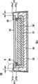
图2是图1的液晶显示装置9的截面图。FIG. 2 is a cross-sectional view of the liquid
如图2中所示,液晶显示装置9包括前部壳体11、后部壳体12以及LCD(液晶显示)保护面板13。As shown in FIG. 2 , the liquid
前部壳体11例如可以是由树脂或镁合金模制的壳体。前部壳体11的下表面通过卡爪(claw)或螺丝结合到后部壳体12的上端部。The
液晶显示保护面板安装表面11a从前部壳体11的上部延伸。由作为丙烯酸(acrylic)聚合物的聚甲基丙烯酸甲酯(PMMA)制成的LCD保护面板13例如通过双面胶带14放置在液晶显示保护面板安装表面11a上。A liquid crystal display protection
图3是图2中的虚线围住的部分A的放大视图。如图3中所示,液晶显示保护面板安装表面11a是基本上与水平面平行的平坦表面。LCD保护面板13的外边缘通过双面胶带14固定到液晶显示保护面板安装表面11a上。此外,在LCD保护面板13的端面与前部壳体11的上部的内表面之间并无间隔,而仅有因尺寸公差而形成的小间隙。FIG. 3 is an enlarged view of a portion A enclosed by a dotted line in FIG. 2 . As shown in FIG. 3, the liquid crystal display protection
返回参阅图2,前部壳体11的内部设置有凹形的(concave)液晶模块支持件16,该液晶模块支持件16具有连接在底面上的基板15。在基板15上安装有诸如芯片电容器(chip capacitor)之类的电子元件,但并未在图2中示出。液晶模块17、18嵌套到液晶模块支持件16的凹部内。顺便指出,该液晶模块38是液晶显示(LCD)面板,而该液晶模块17是用于支持LCD面板18的LCD面板支持件。Referring back to FIG. 2, the inside of the
液晶模块支持件16的上边缘与前部壳体11的上部的下侧接触。液晶模块支持件16支撑前部壳体11。此外,由诸如聚氨酯类橡胶(urethane formrubber)之类的软垫(cushioning)制成的防尘衬垫19放置在LCD面板18的上边缘上。防尘衬垫19与LCD保护面板13的下表面接触。这种结构保护液晶模块17、18不受粉尘的侵入。The upper edge of the liquid
另外,日本公开专利No.2004-111153提出一种背光及液晶显示装置,该装置包括:光源支撑构件,用于将光源支撑在光反射构件的底盘或拐角部,并且其中反射镜部分地位于该底盘与该光源支撑构件之间,并且该光源支撑构件控制该反射镜的前部边缘部在与导光件的前侧平行的方向上相对于该底盘的运动。In addition, Japanese Laid-Open Patent No. 2004-111153 proposes a backlight and liquid crystal display device, which includes: a light source support member for supporting the light source on the chassis or corner of the light reflection member, and wherein the reflector is partially located on the Between the chassis and the light source support member, and the light source support member controls the movement of the front edge portion of the reflector relative to the chassis in a direction parallel to the front side of the light guide.
然而,图2的结构涉及以下问题。参阅与图2类似的图4A和图4B中的截面图,下面描述这些问题。However, the structure of Fig. 2 involves the following problems. Referring to the sectional views in FIGS. 4A and 4B similar to FIG. 2 , these problems are described below.
LCD保护面板13易于因温度上升或因吸收湿气而沿图4中的箭头方向膨胀。LCD保护面板13因吸收湿气而造成的膨胀所引起的伸展量随着吸水量、面板厚度等因素而变化。如果LCD保护面板由例如作为丙烯酸聚合物的聚甲基丙烯酸甲酯(PMMA)制成,则吸水率为0.3%。The
另一方面,如上所述,LCD保护面板13的下表面的外边缘通过双面胶带14固定到液晶显示保护面板安装表面11a上。此外,在LCD保护面板13的端面与前部壳体11的上部的内表面之间并无间隔,而仅有因尺寸公差而形成的小间隙On the other hand, as described above, the outer edge of the lower surface of the
因此,尽管LCD保护面板13易于因温度上升或因吸收湿气而膨胀,但因膨胀而造成的水平方向(图4中的箭头方向)上的伸展却会受限。Therefore, although the
因此,如图4B中所示,LCD保护面板13由于膨胀而向内弯曲(在图4B中为向下),并且在某些情况下LCD保护面板13的下表面与LCD面板18的上表面接触(干涉)。如果LCD保护面板13的下表面与LCD面板18的上表面接触,则接触部分看起来似乎是液滴渗入(droplet infiltrate)到LCD保护面板13与LCD面板18之间。因此,除了修理液晶显示装置9之外别无选择。Therefore, as shown in FIG. 4B , the
针对这一问题,一个可以想到的对策是保证LCD保护面板13的下表面与LCD面板18的上表面之间具有足够的空间,以便即使LCD保护面板13膨胀也不会造成LCD保护面板13的下表面与LCD面板18的上表面彼此接触。然而,这种结构导致液晶显示装置9尺寸增大,并由此导致移动电话10尺寸增大。For this problem, a conceivable countermeasure is to ensure that there is enough space between the lower surface of the LCD
发明内容Contents of the invention
根据实施例的一个方案,液晶显示装置包括:液晶显示面板;液晶显示保护面板,其保护该液晶显示面板的显示表面;以及框架,其在该液晶显示保护面板的一个表面的周边上支撑该液晶显示保护面板,其中,在围绕该液晶显示保护面板的边缘与该框架之间设置有间隙。According to an aspect of the embodiment, a liquid crystal display device includes: a liquid crystal display panel; a liquid crystal display protection panel, which protects a display surface of the liquid crystal display panel; and a frame, which supports the liquid crystal on the periphery of one surface of the liquid crystal display protection panel. A display protection panel, wherein a gap is provided between the edge surrounding the liquid crystal display protection panel and the frame.
附图说明Description of drawings
图1是配备有液晶显示装置的传统移动电话的主视图;FIG. 1 is a front view of a conventional mobile phone equipped with a liquid crystal display device;
图2是图1的液晶显示装置的剖视图;2 is a cross-sectional view of the liquid crystal display device of FIG. 1;
图3是由图2中的虚线围住的部分A的放大视图;Figure 3 is an enlarged view of part A enclosed by the dotted line in Figure 2;
图4A和图4B是示出传统的液晶显示装置的问题的剖视图;4A and 4B are cross-sectional views illustrating problems of a conventional liquid crystal display device;
图5是配备有根据第一实施例的液晶显示装置的移动电话的立体图;5 is a perspective view of a mobile phone equipped with a liquid crystal display device according to the first embodiment;
图6是图5的液晶显示装置的剖视图;6 is a cross-sectional view of the liquid crystal display device of FIG. 5;
图7A和图7B示出图6的液晶显示保护面板的膨胀方式;以及7A and 7B illustrate the expansion mode of the liquid crystal display protection panel of FIG. 6; and
图8是由图6中的虚线围住的部分A的改进的实例的放大视图。FIG. 8 is an enlarged view of a modified example of part A enclosed by a dotted line in FIG. 6 .
具体实施方式Detailed ways
以下将描述实施例。Examples will be described below.
图5是配备有根据第一实施例的液晶显示装置的移动电话的立体图。Fig. 5 is a perspective view of a mobile phone equipped with a liquid crystal display device according to the first embodiment.
图5的移动电话20包括:固定侧壳体21;以及可动侧壳体23,其通过枢轴22与固定侧壳体21以可折叠的方式连接。在图5所示的实例中,移动电话20的可动侧壳体23是打开的。The
固定侧壳体21具有平面的、基本为矩形的形状。固定侧壳体21的内表面24设置有例如多个按钮25、26和27。此外,可动侧壳体23的内表面28设置有例如液晶显示装置29。The fixed-
图6是图5中的液晶显示装置29的剖视图。FIG. 6 is a cross-sectional view of the liquid
如图6中所示,液晶显示装置29包括:LCD(液晶显示)保护面板33;框架41,其为基本上弯折成直角的板状构件;基板35;液晶模块支持件36;液晶模块37、38,嵌套到液晶模块支持件36的凹部内;以及防尘衬垫(dustproof gasket)39。顺便指出,该液晶模块38是液晶显示(LCD)面板,而该液晶模块37是用于支持LCD面板38的LCD面板支持件。As shown in FIG. 6, the liquid
LCD保护面板33是用于保护LCD面板38的显示表面的面板,并且该LCD保护面板33例如由作为丙烯酸聚合物的聚甲基丙烯酸甲酯(PMMA)制成。The
框架41由液晶显示保护面板接触部41a和支持件连接部41b构成,该支持件连接部41b从液晶显示保护面板接触部41a延伸,并弯折成与该液晶显示保护面板接触部41a基本上呈直角。液晶显示保护面板接触部41a位于LCD保护面板33的上表面的两个端部及其附近的上方。支持件连接部41b通过多个卡爪(未图示)与形成在支持件连接部41b上的多个孔(未图示)的接合而连接到液晶模块支持件36上,所述卡爪形成在液晶模块支持件36上的对应位置处。亦即,框架41在连接到液晶模块支持件36的同时,从LCD保护面板33的上方压迫LCD保护面板33的上表面。The
如下文所要详述的,LCD保护面板33的两个端部以预定长度离开框架41的支持件连接部41b的内表面,例如0.2mm。在LCD保护面板33的端部与框架41的支持件连接部41b的内表面之间具有间隙T。As will be described in detail below, both end portions of the
以此方式构造的框架41例如由不锈钢(SAS)制成。如果使用不锈钢(SAS)制造的板状构件作为框架41,则能够减小该装置的总厚度。这里,只要该框架能够从LCD保护面板33的上方压迫LCD保护面板33的上表面,就不特别限制框架41所用的材料。例如,可利用树脂或镁合金模制成框架41。此外,可以将树脂或镁合金模制成保护壳(armor),并用该保护壳覆盖框架41。The
底面连接有基板35的凹形液晶模块支持件36设置在LCD保护面板33的下面。该液晶模块支持件36例如由不锈钢(SAS)制成。这里并不特别限制液晶模块支持件36所用的材料,可以用树脂或镁合金模制成液晶模块支持件36。A concave liquid
诸如芯片电容器之类的电子元件安装在基板35上,但并未在图6中示出。液晶模块37、38嵌套到液晶模块支持件36的凹部内。Electronic components such as chip capacitors are mounted on the
由诸如聚氨酯类橡胶之类的软垫制成的防尘衬垫39放置在LCD面板38的上边缘上,防尘衬垫39与LCD保护面板33下表面接触并支撑LCD保护面板33的下表面。这种结构保护液晶模块37、38不受粉尘的侵入。A
以此方式构造的LCD保护面板33易于因温度上升或因吸收湿气而沿图7A中的箭头方向膨胀。图7A和图7B是与图6类似的截面图。LCD保护面板33的下表面的外边缘并不通过双面胶带14固定(参阅图2),而且LCD保护面板33的两个端部离开框架41的支持件连接部41b的内表面,因此,LCD保护面板33在水平方向(图7A中的箭头方向)上的伸展并不受限。因此,能够在平面方向上吸收这种膨胀,从而LCD保护面板33即使膨胀也不会弯曲。The
换言之,即使在LCD保护面板33沿水平方向(图7A中的箭头方向)膨胀之后,LCD保护面板33的端部与框架41的支持件连接部41b的内表面之间的间隙T也足够大到使LCD保护面板33的端部与框架41的支持件连接部41b的内表面之间保持一定的间隔。因此,即使LCD保护面板33膨胀,仍可保证在LCD保护面板33在宽度方向上的伸展自由度,因此已膨胀的LCD保护面板的端部能够沿着宽度方向(图7A中的箭头方向)伸展。In other words, even after the
如上所述,在该实施例中,该装置被构造为在LCD保护面板33的端部与框架41的支持件连接部41b的内表面之间限定有间隙T,防尘衬垫39支撑LCD保护面板33的下表面,而框架41的液晶显示保护面板接触部41a压迫LCD保护面板33的上表面。As described above, in this embodiment, the device is configured such that the gap T is defined between the end of the
通过这种结构,LCD保护面板33即使膨胀也不会弯曲。因此,能够防止LCD保护面板33的下表面与LCD面板38的上表面接触(干涉)。With this structure, the
此外,由于LCD保护面板33即使膨胀也不会弯曲,因此无需增大LCD保护面板33的下表面与LCD面板38的上表面之间的间隙S。因此,无需增大液晶显示装置29和移动电话20的尺寸。Furthermore, since the
在图6所示的实例中,框架41的液晶显示保护面板接触部41a直接设置在LCD保护面板33的上表面的两个端部及其附近的上方。然而,该实施例并不局限于此,并且也可采用图8中的结构。图8是由图6中的虚线围住的部分A的改进实例的放大视图。In the example shown in FIG. 6 , the liquid crystal display protection
在图8中,框架41的液晶显示保护面板接触部41a例如通过防尘构件50设置在LCD保护面板33的上表面的两个端部及其附近的上方。In FIG. 8 , the liquid crystal display protection
可使用单面胶带或软垫作为防尘构件50。通过将防尘构件50插入到框架41的液晶显示保护面板接触部41a和LCD保护面板33之间,能够确实地防止粉尘从外界侵入。此外,如果使用例如单面胶带或软垫作为防尘构件50,则除了防尘效果之外,还能够获得以下优点。即,即使LCD保护面板33膨胀,LCD保护面板33在水平方向(图7A中箭头的方向)上的伸展也不会受限,从而能够防止LCD保护面板33弯曲。A single-sided tape or a soft pad can be used as the
如上所述,根据该实施例的结构,可防止LCD保护面板33的下表面与LCD面板38的上表面接触(干涉)。因此,在不增大LCD保护面板33的下表面与LCD面板38的上表面之间的间隙的情况下,可以避免看起来似乎是液滴渗入到LCD保护面板33与LCD面板38之间的现象。As described above, according to the structure of this embodiment, the lower surface of the
图6中示出液晶显示装置29的截面。然而,这种结构同样适用于液晶显示装置29的纵向剖视结构。FIG. 6 shows a cross section of the liquid
以上详细描述了实施例。然而,本发明并不局限于上述实施例,而是能够不脱离本发明的范围的情况下加以改进和变化。The embodiments are described above in detail. However, the present invention is not limited to the above-described embodiments, but can be modified and changed without departing from the scope of the present invention.
例如,本发明的上述实施例为了说明的目的而描述了移动电话中的液晶显示装置,但本发明还适用于诸如便携式信息终端(例如PDA,个人数字助理)、诸如膝上型电脑之类的便携式电脑(个人计算机)、桌上型电脑以及电视等其他电子设备中的液晶显示装置。For example, the above-described embodiments of the present invention describe a liquid crystal display device in a mobile phone for illustrative purposes, but the present invention is also applicable to devices such as portable information terminals (eg, PDA, Personal Digital Assistant), devices such as laptop computers, etc. Liquid crystal display devices in portable computers (personal computers), desktop computers, and other electronic equipment such as televisions.
Claims (7)
Translated fromChineseApplications Claiming Priority (2)
| Application Number | Priority Date | Filing Date | Title |
|---|---|---|---|
| JP2007247321 | 2007-09-25 | ||
| JP2007247321AJP2009080164A (en) | 2007-09-25 | 2007-09-25 | Electronic equipment equipped with a liquid crystal display device |
Publications (1)
| Publication Number | Publication Date |
|---|---|
| CN101398546Atrue CN101398546A (en) | 2009-04-01 |
Family
ID=40471203
Family Applications (1)
| Application Number | Title | Priority Date | Filing Date |
|---|---|---|---|
| CNA2008101656455APendingCN101398546A (en) | 2007-09-25 | 2008-09-19 | Liquid crystal display device |
Country Status (3)
| Country | Link |
|---|---|
| US (1) | US20090079901A1 (en) |
| JP (1) | JP2009080164A (en) |
| CN (1) | CN101398546A (en) |
Cited By (5)
| Publication number | Priority date | Publication date | Assignee | Title |
|---|---|---|---|---|
| CN102043285A (en)* | 2010-12-08 | 2011-05-04 | 友达光电股份有限公司 | Display device |
| CN102918576A (en)* | 2010-06-22 | 2013-02-06 | 夏普株式会社 | Display panel and display device |
| CN104793452A (en)* | 2015-04-29 | 2015-07-22 | 小鸟科技有限公司 | Micro projection device |
| CN109633960A (en)* | 2019-01-29 | 2019-04-16 | 惠州市华星光电技术有限公司 | Liquid crystal display die set and liquid crystal display device |
| WO2019237455A1 (en)* | 2018-06-15 | 2019-12-19 | 深圳市柔宇科技有限公司 | Flexible display device, electronic device and fabrication method for flexible display device |
Families Citing this family (4)
| Publication number | Priority date | Publication date | Assignee | Title |
|---|---|---|---|---|
| CN102207639A (en)* | 2010-03-31 | 2011-10-05 | 索尼爱立信移动通讯有限公司 | Display module protective gasket for portable electronic equipment and assembly method for equipment |
| JP5269965B2 (en)* | 2011-10-07 | 2013-08-21 | 株式会社東芝 | Display device |
| JP5798049B2 (en)* | 2012-01-27 | 2015-10-21 | 株式会社ジャパンディスプレイ | Electro-optic device |
| CN103293723B (en) | 2013-06-26 | 2016-01-06 | 深圳市华星光电技术有限公司 | A kind of stationary installation preventing the distortion of display module face glass |
Family Cites Families (7)
| Publication number | Priority date | Publication date | Assignee | Title |
|---|---|---|---|---|
| US5313318A (en)* | 1991-11-04 | 1994-05-17 | Apple Computer, Inc. | Internal frame for a liquid crystal display not extending to the upper surface thereof, light guide and circuitry assembly |
| DE69423552T2 (en)* | 1993-08-10 | 2000-09-07 | Canon K.K., Tokio/Tokyo | Liquid crystal display |
| US20020149714A1 (en)* | 2001-04-16 | 2002-10-17 | Robert Anderson | Ruggedized flat panel display assembly |
| JP3845349B2 (en)* | 2002-09-17 | 2006-11-15 | Nec液晶テクノロジー株式会社 | Backlight and liquid crystal display device |
| JP4774709B2 (en)* | 2004-09-30 | 2011-09-14 | ソニー株式会社 | Liquid crystal display |
| US7599018B2 (en)* | 2005-12-08 | 2009-10-06 | Tpo Displays Corp. | Systems for displaying images including liquid crystal display modules |
| CN101211023B (en)* | 2006-12-29 | 2011-08-24 | 鸿富锦精密工业(深圳)有限公司 | display device |
- 2007
- 2007-09-25JPJP2007247321Apatent/JP2009080164A/enactivePending
- 2008
- 2008-09-09USUS12/230,996patent/US20090079901A1/ennot_activeAbandoned
- 2008-09-19CNCNA2008101656455Apatent/CN101398546A/enactivePending
Cited By (9)
| Publication number | Priority date | Publication date | Assignee | Title |
|---|---|---|---|---|
| CN102918576A (en)* | 2010-06-22 | 2013-02-06 | 夏普株式会社 | Display panel and display device |
| CN102918576B (en)* | 2010-06-22 | 2015-02-25 | 夏普株式会社 | Display panel and display device |
| CN102043285A (en)* | 2010-12-08 | 2011-05-04 | 友达光电股份有限公司 | Display device |
| CN104793452A (en)* | 2015-04-29 | 2015-07-22 | 小鸟科技有限公司 | Micro projection device |
| CN104793452B (en)* | 2015-04-29 | 2016-08-17 | 北京小鸟看看科技有限公司 | A kind of micro-projection device |
| WO2019237455A1 (en)* | 2018-06-15 | 2019-12-19 | 深圳市柔宇科技有限公司 | Flexible display device, electronic device and fabrication method for flexible display device |
| US11432415B2 (en) | 2018-06-15 | 2022-08-30 | Shenzhen Royole Technologies Co., Ltd | Flexible display apparatus, electronic device and manufacturing method for flexible display apparatus |
| CN109633960A (en)* | 2019-01-29 | 2019-04-16 | 惠州市华星光电技术有限公司 | Liquid crystal display die set and liquid crystal display device |
| CN109633960B (en)* | 2019-01-29 | 2021-08-24 | 惠州市华星光电技术有限公司 | Liquid crystal display module and liquid crystal display device |
Also Published As
| Publication number | Publication date |
|---|---|
| US20090079901A1 (en) | 2009-03-26 |
| JP2009080164A (en) | 2009-04-16 |
Similar Documents
| Publication | Publication Date | Title |
|---|---|---|
| JP4625063B2 (en) | Electronic equipment equipped with a liquid crystal display device | |
| CN101398546A (en) | Liquid crystal display device | |
| US9232667B2 (en) | Display device | |
| US6888591B2 (en) | LCD assembly used with a personal digital assistant | |
| CN208000440U (en) | Liquid crystal module and display device | |
| US10742788B2 (en) | Mobile terminal | |
| US8047668B2 (en) | Display device, backlight module of such display device, and method of fixing circuit board on such backlight module | |
| CN216697668U (en) | Display components and electronic equipment | |
| JP2005091971A (en) | Display device | |
| US20130107157A1 (en) | Liquid crystal display | |
| CN102506344B (en) | Backlight module and display device using same | |
| EP3089140B1 (en) | Display apparatus | |
| JP4802809B2 (en) | Double-sided LCD module | |
| JP4731410B2 (en) | Liquid crystal display module and liquid crystal display device | |
| JP5522732B2 (en) | Support structure for liquid crystal display and electronic device | |
| JP2013239335A (en) | Backlight unit and liquid crystal display device | |
| US20120081865A1 (en) | Dustproof structure and electronic device employing the same | |
| TW200821689A (en) | Liquid crystal display device | |
| JP5168260B2 (en) | Electronic equipment equipped with a liquid crystal display device | |
| TW200809317A (en) | Liquid crystal display device | |
| CN112639923A (en) | Flexible display device | |
| CN104054121A (en) | Display device and television receiver | |
| US20060256514A1 (en) | Pressure resistance cover for the display panel of a portable computer | |
| JP2010015189A (en) | Electronic device including liquid crystal display device | |
| CN101321445B (en) | portable electronic device |
Legal Events
| Date | Code | Title | Description |
|---|---|---|---|
| C06 | Publication | ||
| PB01 | Publication | ||
| C10 | Entry into substantive examination | ||
| SE01 | Entry into force of request for substantive examination | ||
| C02 | Deemed withdrawal of patent application after publication (patent law 2001) | ||
| WD01 | Invention patent application deemed withdrawn after publication | Application publication date:20090401 |