CN101385198B - portable radio - Google Patents
portable radioDownload PDFInfo
- Publication number
- CN101385198B CN101385198BCN2007800058585ACN200780005858ACN101385198BCN 101385198 BCN101385198 BCN 101385198BCN 2007800058585 ACN2007800058585 ACN 2007800058585ACN 200780005858 ACN200780005858 ACN 200780005858ACN 101385198 BCN101385198 BCN 101385198B
- Authority
- CN
- China
- Prior art keywords
- antennas
- receiving antenna
- antenna
- housing
- circuit board
- Prior art date
- Legal status (The legal status is an assumption and is not a legal conclusion. Google has not performed a legal analysis and makes no representation as to the accuracy of the status listed.)
- Expired - Fee Related
Links
Images


Classifications
- H—ELECTRICITY
- H01—ELECTRIC ELEMENTS
- H01Q—ANTENNAS, i.e. RADIO AERIALS
- H01Q1/00—Details of, or arrangements associated with, antennas
- H01Q1/12—Supports; Mounting means
- H01Q1/22—Supports; Mounting means by structural association with other equipment or articles
- H01Q1/24—Supports; Mounting means by structural association with other equipment or articles with receiving set
- H01Q1/241—Supports; Mounting means by structural association with other equipment or articles with receiving set used in mobile communications, e.g. GSM
- H01Q1/242—Supports; Mounting means by structural association with other equipment or articles with receiving set used in mobile communications, e.g. GSM specially adapted for hand-held use
- H01Q1/243—Supports; Mounting means by structural association with other equipment or articles with receiving set used in mobile communications, e.g. GSM specially adapted for hand-held use with built-in antennas
- H—ELECTRICITY
- H01—ELECTRIC ELEMENTS
- H01Q—ANTENNAS, i.e. RADIO AERIALS
- H01Q1/00—Details of, or arrangements associated with, antennas
- H01Q1/52—Means for reducing coupling between antennas; Means for reducing coupling between an antenna and another structure
- H—ELECTRICITY
- H01—ELECTRIC ELEMENTS
- H01Q—ANTENNAS, i.e. RADIO AERIALS
- H01Q21/00—Antenna arrays or systems
- H01Q21/28—Combinations of substantially independent non-interacting antenna units or systems
- H—ELECTRICITY
- H04—ELECTRIC COMMUNICATION TECHNIQUE
- H04B—TRANSMISSION
- H04B7/00—Radio transmission systems, i.e. using radiation field
- H04B7/02—Diversity systems; Multi-antenna system, i.e. transmission or reception using multiple antennas
- H04B7/04—Diversity systems; Multi-antenna system, i.e. transmission or reception using multiple antennas using two or more spaced independent antennas
- H04B7/08—Diversity systems; Multi-antenna system, i.e. transmission or reception using multiple antennas using two or more spaced independent antennas at the receiving station
- H—ELECTRICITY
- H04—ELECTRIC COMMUNICATION TECHNIQUE
- H04M—TELEPHONIC COMMUNICATION
- H04M1/00—Substation equipment, e.g. for use by subscribers
- H04M1/02—Constructional features of telephone sets
- H04M1/0202—Portable telephone sets, e.g. cordless phones, mobile phones or bar type handsets
- H04M1/0206—Portable telephones comprising a plurality of mechanically joined movable body parts, e.g. hinged housings
- H04M1/0208—Portable telephones comprising a plurality of mechanically joined movable body parts, e.g. hinged housings characterized by the relative motions of the body parts
- H04M1/0214—Foldable telephones, i.e. with body parts pivoting to an open position around an axis parallel to the plane they define in closed position
Landscapes
- Engineering & Computer Science (AREA)
- Computer Networks & Wireless Communication (AREA)
- Signal Processing (AREA)
- Support Of Aerials (AREA)
- Telephone Set Structure (AREA)
- Details Of Aerials (AREA)
Abstract
Description
Translated fromChinese技术领域technical field
本发明涉及一种具有两个天线的分集型便携式无线机。The present invention relates to a diversity type portable radio having two antennas.
背景技术Background technique
便携式电话机等便携式无线机中,应用了分集技术的便携式无线机越来越普及,其中分集技术是具有两个天线,针对用该天线接收到的同一接收信号,优先采用电波状况良好的天线的信号、或者改变两个天线的接收信号的合成的加权的技术。Among portable wireless devices such as portable telephones, portable wireless devices using diversity technology, which has two antennas and preferentially uses the antenna with good radio wave conditions for the same received signal received by the antennas, are becoming more and more popular. signal, or a technique that changes the weighting of the combination of received signals from two antennas.
另外,在便携式无线机中,从设计上的需求等出发,在壳体内内置了天线的便携式无线机逐渐成为主流。例如,在折叠式的便携式电话机中,提出了在具有按键操作部的壳体内内置了天线的折叠式的便携式电话机(参照专利文献1)。In addition, among portable wireless devices, a portable wireless device with an antenna built in a housing is gradually becoming mainstream due to design requirements and the like. For example, among foldable mobile phones, there has been proposed a foldable mobile phone in which an antenna is built in a casing having a key operation unit (see Patent Document 1).
专利文献1:日本专利公开公报、特开2003-8320号Patent Document 1: Japanese Patent Laid-Open Gazette, Japanese Patent Laid-Open No. 2003-8320
然而,在分集型便携式无线机中,若两个天线的距离靠近则产生天线间的干扰而导致天线效率恶化,因此,需要使两个天线充分地保持距离。However, in a diversity type portable wireless device, if the distance between the two antennas is close, interference between the antennas will occur and the efficiency of the antenna will deteriorate. Therefore, it is necessary to maintain a sufficient distance between the two antennas.
然而,从便携式无线机的小型化的需求出发,在不少的情况下不得不将两个天线配置在靠近的位置。在该情况下,如上所述那样存在两个天线干扰而导致天线特性降低的问题。However, due to the need for miniaturization of portable wireless devices, in many cases it is necessary to arrange the two antennas at close positions. In this case, as described above, there is a problem that the two antennas interfere to degrade the antenna characteristics.
发明内容Contents of the invention
本发明是鉴于上述情况而作成的,其目的在于提供一种在将两个天线内置在壳体内的分集型的便携式无线机中,即使在将两个天线靠近配置的情况下,也可容易地抑制天线干扰的便携式无线机。The present invention has been made in view of the above circumstances, and an object of the present invention is to provide a diversity-type portable wireless device in which two antennas are built in a housing, which can easily Portable radio that suppresses antenna interference.
因而,本发明的便携式无线机是一种分集型便携式无线机,具有:Thus, the portable radio of the present invention is a diversity type portable radio having:
两个天线;two antennas;
壳体;和shell; and
电路基板,其设置在所述壳体内,并且形成有基准电位部;a circuit substrate disposed within the housing and formed with a reference potential portion;
所述两个天线配置在所述壳体内的一方端部;The two antennas are arranged at one end of the housing;
所述两个天线中至少一个天线安装在所述电路基板上;At least one of the two antennas is mounted on the circuit substrate;
在所述一个天线的附近配置具有与所述基准电位部电连接的金属部的部件。A member having a metal portion electrically connected to the reference potential portion is disposed near the one antenna.
优选地,所述一个天线是接收天线。Advantageously, said one antenna is a receive antenna.
优选地,具有所述金属部的部件是配置在所述电路基板上以覆盖安装在的电子部件的屏蔽盒、或者是安装在所述电路基板的耳机塞孔、或者是安装在所述电路基板的卡连接器。Preferably, the component having the metal part is a shielding box disposed on the circuit substrate to cover the electronic components mounted on it, or an earphone jack mounted on the circuit substrate, or a shielding box mounted on the circuit substrate card connector.
发明効果Invention effect
根据本发明的便携式无线机,在配置于构成便携式无线机的壳体内的分集方式的两个天线之中,在一个天线的附近配置具有与设置在壳体内的电路基板的基准电位部电连接的金属部的部件,以使所述一方天线的天线增益恶化,由此降低另一个天线的天线增益的劣化,通过这样,可以避免因两个天线干扰而该两个天线的天线增益同时恶化的情况。According to the portable wireless device of the present invention, among the two antennas of the diversity method arranged in the housing of the portable wireless device, the antenna having the electric connection electrically connected to the reference potential portion of the circuit board provided in the housing is disposed near one of the antennas. Metal parts, so that the antenna gain of the one antenna deteriorates, thereby reducing the degradation of the antenna gain of the other antenna, through this, it is possible to avoid the simultaneous deterioration of the antenna gain of the two antennas due to the interference of the two antennas .
从而,即使在壳体内的一端侧配置了两个天线,也可以良好地进行分集接收。另外,由于天线配置的自由度、甚至便携式无线机的设计的自由度扩大,因此可以实现便携式电话机的小型化、薄形化。Therefore, even if two antennas are arranged on one end side inside the casing, diversity reception can be performed satisfactorily. In addition, since the degree of freedom in antenna arrangement and even the degree of freedom in design of the portable wireless device is increased, it is possible to reduce the size and thickness of the mobile phone.
附图说明Description of drawings
图1是表示本发明的一种实施方式的便携式电话机的整体的外观立体图。FIG. 1 is a perspective view showing the overall appearance of a mobile phone according to an embodiment of the present invention.
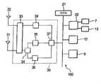
图2是表示图1的便携式电话机的结构的方框图。FIG. 2 is a block diagram showing the structure of the cellular phone shown in FIG. 1. FIG.
图3是表示本发明的一种实施方式的便携式电话机中的第一壳体的结构的分解立体图。3 is an exploded perspective view showing the structure of a first housing in the cellular phone according to the embodiment of the present invention.
图4(a)是表示本发明的一种实施方式的便携式电话机中的第一壳体的前端部的组装状态的立体图。Fig. 4(a) is a perspective view showing an assembled state of the front end portion of the first housing in the cellular phone according to the embodiment of the present invention.
图4(b)是表示本发明的一种实施方式的便携式电话机中的第一壳体的前端部的组装状态的剖视图。Fig. 4(b) is a cross-sectional view showing an assembled state of the front end portion of the first housing in the cellular phone according to the embodiment of the present invention.
图5是表示取代屏蔽盒而使耳机塞孔靠近接收天线的示例的立体图。5 is a perspective view showing an example in which an earphone jack is brought closer to a receiving antenna instead of a shield case.
图6是表示取代屏蔽盒而使卡连接器靠近接收天线的示例的立体图。FIG. 6 is a perspective view showing an example in which a card connector is brought closer to a receiving antenna instead of a shield case.
符号的説明Explanation of symbols
1第一壳体1 first housing
5电路基板5 circuit substrate
5a表面5a surface
5b背面5b back
6屏蔽盒6 shielding box
31收发天线31 transceiver antenna
32接收天线32 receiving antenna
具体实施方式Detailed ways
下面,参照附图,说明本发明的实施方式相关的便携式无线机。Hereinafter, a portable wireless device according to an embodiment of the present invention will be described with reference to the drawings.
图1是表示本实施方式相关的便携式电话机100的整体的外观立体图。FIG. 1 is a perspective view showing the overall appearance of a
该便携式电话机100是CDMA(Code Division Multiple Access)2000 1x以及CDMA2000 1x EVDO(Evolution Data Only)方式的电话机,其具备:第一壳体1,其具备接受用户的操作的按键操作部9等;和第二壳体11,其具备主显示器12等;第一壳体1与第二壳体11经形成在各自的一端的铰链部2可对置折叠并打开闭合自如地连接在一起。The
第一壳体1具有第一外壳构件3和第二外壳构件4。在第一壳体1中,在闭合状态下与第二壳体11对置的对置面1a上,露出设置了具有通话按键、结束通话按键等的按键操作部9,在该按键操作部9的下方配置了话筒7。第一壳体1的外面的一部分由盖构件3a来形成,在其内部容纳二次电池8(参照图3)。The
在第二壳体11中,在闭合状态下与第一壳体1对置的对置面11a上露出配置了由液晶显示器、有机EL显示器、无机EL显示器等构成的主显示器12,在该主显示器12的上方配置了扬声器13。In the
另外,在扬声器13的左右分别在突出的状态下安装了衬垫部件14、通过该衬垫部件14,在使第一壳体1与第二壳体11进行闭合动作时,可防止第一壳体1与第二壳体11直接接触。In addition, a
图2是表示图1所示的便携式电话机100的结构的方框图。FIG. 2 is a block diagram showing the configuration of
便携式电话机100具备:集中控制便携式电话机的CPU等的制御部21、按键操作部9、主显示器12、连接在话筒7以及扬声器13并处理声音信号的声音处理部22、无线通信部30等。The
无线通信部30是进行分集接收的部分,具备收发天线31和接收天线32。收发天线31经进行两个天线31、32的切换的高频开关33、天线共用器34、第一接收电路35、发送电路36而连接到通信处理部37。接收天线32经高频开关33以及第二接收电路39而连接到通信处理部37。The
通过这种结构,在CDMA2000 1x EVDO方式下,天线31、32接收到来自未图示的基站的无线电波,则通信处理部37对经两个天线31、天线32而输入到第一接收电路35以及第二接收电路39的无线信号进行合成,并处理该无线信号。With this configuration, in the CDMA2000 1x EVDO mode, the
另外,通信处理部37经发送电路36、天线共用器34、高频开关33以及收发天线31向基站发送无线信号。In addition, the
图3是表示图1所示的便携式电话机的第一壳体的详细构造的分解立体图。Fig. 3 is an exploded perspective view showing a detailed structure of a first housing of the cellular phone shown in Fig. 1 .
在第一壳体1的内部设置有电路基板5、屏蔽盒(包含金属部的部件)6、按键操作部9。须指出的是,参照编号8是在第一外壳构件3与盖构件3a之间所形成的空间内容纳的二次电池8。Inside the
在电路基板5上安装有集成电路、电阻器、电容器等电子部件,并且形成有连接上述部件之间的连接布线图案和基准电位图案(接地图案)。此外,在电路基板5上安装有接收天线32(参照图4(b)、5)。Electronic components such as integrated circuits, resistors, and capacitors are mounted on the
屏蔽盒6是具有导电性的箱状的构件,其包括:金属制造的顶板9a,其形成为具有覆盖电路基板5的表面5a(按键操作部9侧的面)的尺寸的平板状;和多个壁部9b,其由覆盖了导电膜的树脂构成,并且设置为从所述顶板9a垂直突出;所述屏蔽盒6配置成夹持电路基板5而配置在二次电池8的相反侧以覆盖电路基板5的表面5a(按键操作部9侧的面)。The
屏蔽盒6相对电路基板5在多处被螺丝固定,并且与电路基板5的基准电位部(接地部)电连接。从而,可防止电路基板5的表面5a上安装的电子部件因电磁波等而受到外部干扰。而且,电路基板5、安装固定在该电路基板5的屏蔽盒6、以及设置在屏蔽盒6的顶板9a上的按键操作部9,配置在由对置状态下接合的第一外壳构件3和第二外壳构件4所形成的空间内。The
须指出的是,虽然示出了利用金属来形成构成屏蔽盒6的顶板9a,利用以导电膜覆盖的树脂来形成壁部9b的示例,但是,只要整体上具有导电性即可,例如也可以利用金属来形成屏蔽盒6的整体、或者也可以用树脂来一体形成顶板9a以及壁部9b,然后在整体上覆盖导电膜。尤其,利用以导电膜覆盖的树脂来形成屏蔽盒6的整体,由此可以抑制整体的重量,因此,可以使便携式电话机100进一步轻量化。It should be noted that although the example in which the
另外,图4(a)是表示第一壳体的前端部(一端部)的组装状态的立体图,图4(b)表示第一壳体的前端部(一端部)的剖视图,如图4(a)、(b)所示,电路基板5配置在第一壳体1的内部的前端部(一端部)为止。另外,在第一壳体1的内部中,在其前端与电路基板5之间的空间内配置有收发天线31。In addition, Fig. 4 (a) is a perspective view showing the assembled state of the front end (one end) of the first housing, and Fig. 4 (b) shows a sectional view of the front end (one end) of the first housing, as shown in Fig. 4 ( As shown in a) and (b), the
在电路基板5中的收发天线31的附近,配置有安装在电路基板5的接收天线32。A receiving
而且,由图4(b)可看出,安装在电路基板5上的接收天线32被与电路基板5的基准电位部电连接的屏蔽盒6覆盖。也即,采用了在接收天线32的附近配置了与电路基板5的基准电位部电连接的屏蔽盒6的结构。Furthermore, as can be seen from FIG. 4( b ), the receiving
也即,收发天线31以及接收天线32在同一频带或者附近的频带具有天线增益。如果靠近配置这种两个天线31、32,则两个天线31、32彼此电磁耦合,因而天线增益就会彼此恶化。也就是说,发生两个天线31、32之间耦合的现象,发送电波、接收电波就会彼此分散,与单体中使用的情况相比,天线增益还要恶化。That is, the transmitting and receiving
因而,如图4(b)所示,在接收天线32的附近配置与电路基板5的基准电位部电连接的屏蔽盒6。从而,虽然接收天线32的天线增益恶化,但是可以降低收发天线31的天线增益的恶化。也即,通过预先使接收天线32的天线增益恶化,来抑制接收天线32与收发天线31之间的干扰,并降低收发天线31的天线增益的恶化,从而可防止两个天线的增益均恶化。Therefore, as shown in FIG. 4( b ), the
从而,便携式电话机100可以良好地进行采用了两个天线31、32的分集接收。另外,由于可以在一个壳体1内靠近配置两个天线31、32,因此,可以实现便携式电话机100的小型化、薄形化。Therefore, the
尤其,接收天线32是接收专用的天线,不会象收发天线31那样还使用于发送,因此为了得到分集効果而不需要收发天线31程度的天线增益。为此,屏蔽盒6最好靠近于接收天线32。In particular, the receiving
其中,如果使接收天线32与屏蔽盒6过于靠近,则辐射被切断、或者因与基准电位部的耦合而无法发挥天线的功能,因此,最好是在可得到分集効果的最低限度的天线增益的范围内适当地靠近。Among them, if the receiving
图5是表示取代屏蔽盒而使耳机塞孔靠近接收天线的示例的立体图,图6是表示取代屏蔽盒而使卡连接器靠近接收天线的示例的立体图。5 is a perspective view showing an example in which an earphone jack is brought closer to a receiving antenna instead of a shield box, and FIG. 6 is a perspective view showing an example in which a card connector is brought closer to a receiving antenna instead of a shield box.
图5和图6示出的是在与安装了接收天线32的表面5a相反侧的背面5b的与接收天线32对置的位置安装配置了耳机塞孔41或者卡连接器45。也即,耳机塞孔41、卡连接器45具备与连接布线图案连接、而且还与基准电位图案连接的金属部41a,45a,可在接收天线32的附近配置与基准电位图案电连接的金属部。这样,通过将耳机塞孔41、卡连接器45配置在接收天线32的附近,也可以与屏蔽盒6的示例同样地降低接收天线32的天线增益,由此抑制接收天线32与收发天线31之间的干扰,降低收发天线31的天线增益的恶化,因此可以防止两个天线31、32的增益恶化。5 and 6 show that the
须指出的是,在该情况下,为了使接收天线32的天线增益不过分地降低,在屏蔽盒6中将设置有接收天线32的部位切除、或者形成为非导电性。In this case, in order not to reduce the antenna gain of the receiving
以上、在上述的实施方式中示出的各结构构件的诸多形状、组合等是一个示例,在不脱离本发明的要旨的范围内,可根据设计要求等,进行各种变更。Various shapes, combinations, and the like of the respective structural members shown in the above-mentioned embodiments are examples, and various changes can be made in accordance with design requirements and the like without departing from the gist of the present invention.
例如、在上述的实施方式中,示出了作为包含配置在接收天线32的附近的金属部的部件,采用屏蔽盒6、耳机塞孔41、卡连接器45等的示例,但是本发明不仅限于上述部件,只要是螺丝、充电端子、表备份电路的按钮电池等包含与电路基板的基准电位部电连接的金属部的部件即可。另外,对降低接收天线32中的天线增益的程度而言,由于根据金属部的尺寸、与接收天线32的距离、此外收发天线31与接收天线32之间的距离,规定接收天线32的天线增益的恶化的程度,因此只要在可得到分集効果的最低限度的天线增益的范围内适当地设定即可。For example, in the above-mentioned embodiment, an example in which the
另外,作为分集接收的方式,比较两个天线的接收信号的S/N比等,通过由通信处理部37优化各接收信号的加权来进行接收的CDMA2000EVDO中进行了说明,但是还可以应用于例如W-CDMA HSDPA(HighSpeed Data Packet Access)等。In addition, as a method of diversity reception, the S/N ratio of received signals of two antennas is compared, and the
另外,作为内置有两个天线31、32的壳体,不限于第一壳体1,也可以是第二壳体11。In addition, the housing in which the two
另外,不限于壳体的前端部,也可以是侧端部等。无论是怎样的情况,只要是两个天线31、32靠近而发送天线间干扰的情况,均可以应用本发明。In addition, it is not limited to the front end portion of the case, but may be a side end portion or the like. In any case, the present invention can be applied as long as the two
此外,在上述的实施方式中,说明了便携式电话机100,但是不限于此。只要是具备进行分集接收的无线部的便携式电子设备,也可以是例如PDA(Personal Digital Assistants)等。In addition, in the above-mentioned embodiment, the
本申请是根据于2006年2月24日申请的日本专利申请(特愿2006-049061)的专利申请,在此参考并引用其内容。This application is based on Japanese Patent Application (Japanese Patent Application No. 2006-049061 ) filed on February 24, 2006, the contents of which are incorporated herein by reference.
Claims (4)
Translated fromChineseApplications Claiming Priority (3)
| Application Number | Priority Date | Filing Date | Title |
|---|---|---|---|
| JP049061/2006 | 2006-02-24 | ||
| JP2006049061 | 2006-02-24 | ||
| PCT/JP2007/053319WO2007099859A1 (en) | 2006-02-24 | 2007-02-22 | Portable wireless device |
Publications (2)
| Publication Number | Publication Date |
|---|---|
| CN101385198A CN101385198A (en) | 2009-03-11 |
| CN101385198Btrue CN101385198B (en) | 2012-09-26 |
Family
ID=38458970
Family Applications (1)
| Application Number | Title | Priority Date | Filing Date |
|---|---|---|---|
| CN2007800058585AExpired - Fee RelatedCN101385198B (en) | 2006-02-24 | 2007-02-22 | portable radio |
Country Status (5)
| Country | Link |
|---|---|
| US (1) | US8138979B2 (en) |
| JP (1) | JP5086236B2 (en) |
| KR (1) | KR20080100207A (en) |
| CN (1) | CN101385198B (en) |
| WO (1) | WO2007099859A1 (en) |
Families Citing this family (5)
| Publication number | Priority date | Publication date | Assignee | Title |
|---|---|---|---|---|
| CN101754606B (en)* | 2008-12-04 | 2013-05-29 | 深圳富泰宏精密工业有限公司 | Electronic device |
| JP5523484B2 (en)* | 2012-01-11 | 2014-06-18 | パナソニック株式会社 | Mobile device |
| DE102016118629A1 (en)* | 2016-06-09 | 2017-12-14 | Hirschmann Car Communication Gmbh | Communication system of a vehicle with improved thermal management |
| CN107317089B (en)* | 2017-07-11 | 2023-12-26 | 信维创科通信技术(北京)有限公司 | Antenna module structure and communication terminal |
| EP4332722A4 (en)* | 2021-09-16 | 2024-09-11 | Samsung Electronics Co., Ltd. | ELECTRONIC DEVICE WITH FLEXIBLE DISPLAY AND CONTROL METHOD THEREFOR |
Family Cites Families (24)
| Publication number | Priority date | Publication date | Assignee | Title |
|---|---|---|---|---|
| US3573628A (en)* | 1968-07-15 | 1971-04-06 | Motorola Inc | Antenna for miniature radio receiver including portions of receiver housing and chassis |
| JP3251680B2 (en)* | 1991-12-26 | 2002-01-28 | 株式会社東芝 | Portable radio |
| JPH0983229A (en) | 1995-09-19 | 1997-03-28 | Fujitsu Ltd | Wireless LAN connection circuit |
| JP2968716B2 (en) | 1996-04-23 | 1999-11-02 | 埼玉日本電気株式会社 | Diversity receiver |
| JPH09331282A (en) | 1996-06-12 | 1997-12-22 | Saitama Nippon Denki Kk | Antenna changeover diversity circuit |
| JPH11298231A (en)* | 1998-04-06 | 1999-10-29 | Matsushita Electric Ind Co Ltd | Antenna device |
| JP3317945B2 (en) | 1999-01-26 | 2002-08-26 | 埼玉日本電気株式会社 | Diversity switching circuit |
| JP3119642B2 (en) | 1999-01-26 | 2000-12-25 | 埼玉日本電気株式会社 | Unselected branch termination condition switching circuit |
| JP3432768B2 (en)* | 1999-04-15 | 2003-08-04 | 松下電器産業株式会社 | Antennas for portable communication terminals |
| JP2001057529A (en)* | 1999-08-18 | 2001-02-27 | Mitsubishi Electric Corp | Wireless device |
| EP1124279A1 (en)* | 2000-02-08 | 2001-08-16 | Hewlett-Packard Company, A Delaware Corporation | Wireless transmission card |
| TW501799U (en)* | 2000-05-23 | 2002-09-01 | Hon Hai Prec Ind Co Ltd | Socket connector |
| JP2002171109A (en) | 2000-11-30 | 2002-06-14 | Toshiba Corp | Mobile communication terminal and antenna mounting structure used for this mobile communication terminal |
| JP3631696B2 (en) | 2001-06-25 | 2005-03-23 | 埼玉日本電気株式会社 | Portable radio |
| JP2003046407A (en) | 2002-05-15 | 2003-02-14 | Sharp Corp | Portable radio |
| JP2004159288A (en) | 2002-09-12 | 2004-06-03 | Seiko Epson Corp | Antenna device, printed wiring board, printed circuit board, communication adapter, and portable electronic device |
| EP1560342A4 (en)* | 2002-11-07 | 2012-08-01 | Panasonic Corp | COMMUNICATIONS TERMINAL |
| JP2004364149A (en)* | 2003-06-06 | 2004-12-24 | Murata Mfg Co Ltd | Radio communication equipment |
| US6932626B2 (en)* | 2003-06-30 | 2005-08-23 | Tyco Electronics Corporation | Electrical card connector |
| TW200512566A (en)* | 2003-09-19 | 2005-04-01 | Quanta Comp Inc | Concealed antenna used in a notebook |
| JP4289610B2 (en) | 2003-11-17 | 2009-07-01 | ソニー・エリクソン・モバイルコミュニケーションズ株式会社 | Wireless communication terminal device |
| KR100623079B1 (en)* | 2004-05-11 | 2006-09-19 | 학교법인 한국정보통신학원 | Stacked Structure Multiband Antenna |
| JP4114649B2 (en) | 2004-07-15 | 2008-07-09 | セイコーエプソン株式会社 | Wireless communication terminal |
| US7362275B2 (en)* | 2006-02-14 | 2008-04-22 | Palm, Inc. | Internal antenna and motherboard architecture |
- 2007
- 2007-02-22JPJP2008502744Apatent/JP5086236B2/ennot_activeExpired - Fee Related
- 2007-02-22WOPCT/JP2007/053319patent/WO2007099859A1/enactiveApplication Filing
- 2007-02-22KRKR1020087020653Apatent/KR20080100207A/ennot_activeCeased
- 2007-02-22CNCN2007800058585Apatent/CN101385198B/ennot_activeExpired - Fee Related
- 2007-02-22USUS12/279,758patent/US8138979B2/ennot_activeExpired - Fee Related
Also Published As
| Publication number | Publication date |
|---|---|
| KR20080100207A (en) | 2008-11-14 |
| WO2007099859A1 (en) | 2007-09-07 |
| JP5086236B2 (en) | 2012-11-28 |
| US8138979B2 (en) | 2012-03-20 |
| JPWO2007099859A1 (en) | 2009-07-16 |
| US20100231458A1 (en) | 2010-09-16 |
| CN101385198A (en) | 2009-03-11 |
Similar Documents
| Publication | Publication Date | Title |
|---|---|---|
| KR101027634B1 (en) | Communication device for use in one or more communication systems | |
| RU2354043C2 (en) | Device for communication with internal antenna system | |
| US8665164B2 (en) | Multiband handheld electronic device slot antenna | |
| JP4242780B2 (en) | Balanced multiband antenna device | |
| US7768462B2 (en) | Multiband antenna for handheld electronic devices | |
| JP4828482B2 (en) | Portable wireless device | |
| US8606195B2 (en) | Radio | |
| CN102738556A (en) | Antenna device for portable terminal and portable terminal with antenna device | |
| EP1686647B1 (en) | Mobile communication terminal | |
| JPWO2009034648A1 (en) | Wireless communication device | |
| CN101385198B (en) | portable radio | |
| JP2008227560A (en) | Portable wireless apparatus | |
| JP2009111698A (en) | Mobile terminal and power supply cable wiring method for mobile terminal | |
| JP4663492B2 (en) | Portable wireless device | |
| US20090270146A1 (en) | Cellular Phone | |
| WO2005096437A1 (en) | Portable wireless unit | |
| US20110267239A1 (en) | Portable radio device | |
| RU2523443C2 (en) | Antenna device for portable wireless terminal | |
| WO2012157233A1 (en) | Portable wireless device | |
| JP3715607B2 (en) | Portable wireless device | |
| US7183986B2 (en) | Device and method for improving a radiation pattern of a mobile wireless terminal with a built-in antenna | |
| KR100810317B1 (en) | Apparatus and method for controlling antenna interference signal of portable terminal supporting reinforcement device | |
| JP4079810B2 (en) | Mobile phone | |
| JP2007180683A (en) | Portable radio | |
| JP2007180658A (en) | Portable radio |
Legal Events
| Date | Code | Title | Description |
|---|---|---|---|
| C06 | Publication | ||
| PB01 | Publication | ||
| C10 | Entry into substantive examination | ||
| SE01 | Entry into force of request for substantive examination | ||
| C14 | Grant of patent or utility model | ||
| GR01 | Patent grant | ||
| CF01 | Termination of patent right due to non-payment of annual fee | ||
| CF01 | Termination of patent right due to non-payment of annual fee | Granted publication date:20120926 Termination date:20200222 |