CN101384946B - Spectacle frame with magnetic lens mount - Google Patents
Spectacle frame with magnetic lens mountDownload PDFInfo
- Publication number
- CN101384946B CN101384946BCN2007800056151ACN200780005615ACN101384946BCN 101384946 BCN101384946 BCN 101384946BCN 2007800056151 ACN2007800056151 ACN 2007800056151ACN 200780005615 ACN200780005615 ACN 200780005615ACN 101384946 BCN101384946 BCN 101384946B
- Authority
- CN
- China
- Prior art keywords
- lens
- frame
- magnetic element
- magnet
- magnetic
- Prior art date
- Legal status (The legal status is an assumption and is not a legal conclusion. Google has not performed a legal analysis and makes no representation as to the accuracy of the status listed.)
- Expired - Fee Related
Links
Images


Classifications
- G—PHYSICS
- G02—OPTICS
- G02C—SPECTACLES; SUNGLASSES OR GOGGLES INSOFAR AS THEY HAVE THE SAME FEATURES AS SPECTACLES; CONTACT LENSES
- G02C1/00—Assemblies of lenses with bridges or browbars
- G02C1/02—Bridge or browbar secured to lenses without the use of rims
- G—PHYSICS
- G02—OPTICS
- G02C—SPECTACLES; SUNGLASSES OR GOGGLES INSOFAR AS THEY HAVE THE SAME FEATURES AS SPECTACLES; CONTACT LENSES
- G02C1/00—Assemblies of lenses with bridges or browbars
- G02C1/04—Bridge or browbar secured to or integral with partial rims, e.g. with partially-flexible rim for holding lens
- G—PHYSICS
- G02—OPTICS
- G02C—SPECTACLES; SUNGLASSES OR GOGGLES INSOFAR AS THEY HAVE THE SAME FEATURES AS SPECTACLES; CONTACT LENSES
- G02C1/00—Assemblies of lenses with bridges or browbars
- G02C1/10—Special mounting grooves in the rim or on the lens
- G—PHYSICS
- G02—OPTICS
- G02C—SPECTACLES; SUNGLASSES OR GOGGLES INSOFAR AS THEY HAVE THE SAME FEATURES AS SPECTACLES; CONTACT LENSES
- G02C2200/00—Generic mechanical aspects applicable to one or more of the groups G02C1/00 - G02C5/00 and G02C9/00 - G02C13/00 and their subgroups
- G02C2200/02—Magnetic means
- G—PHYSICS
- G02—OPTICS
- G02C—SPECTACLES; SUNGLASSES OR GOGGLES INSOFAR AS THEY HAVE THE SAME FEATURES AS SPECTACLES; CONTACT LENSES
- G02C2200/00—Generic mechanical aspects applicable to one or more of the groups G02C1/00 - G02C5/00 and G02C9/00 - G02C13/00 and their subgroups
- G02C2200/08—Modular frames, easily exchangeable frame parts and lenses
Landscapes
- Physics & Mathematics (AREA)
- Health & Medical Sciences (AREA)
- General Physics & Mathematics (AREA)
- Ophthalmology & Optometry (AREA)
- Optics & Photonics (AREA)
- Eyeglasses (AREA)
Abstract
Description
Translated fromChinese本申请基于2006年1月13日提交的申请号为60/758,562的临时专利申请4。This application is based on
技术领域technical field
本发明涉及一种带有磁性镜片安装装置的眼镜架。更特别地,本发明涉及一种眼镜架,使用者可通过简单并且方便的方式对处方镜片或平光镜片和/或平视护目罩进行更换,可以容易拆卸的方式将镜片装于镜架。 The invention relates to a spectacle frame with a magnetic lens mounting device. More particularly, the present invention relates to a spectacle frame in which a user can replace a prescription lens or a plano lens and/or a head-up goggle in a simple and convenient manner, and the lens can be attached to the spectacle frame in an easily detachable manner. the
背景技术Background technique
一副典型的眼镜包括:一对镜片或单个护目罩,安装在镜架上,此镜架可包括围绕镜片的包边;额头横梁;桥接件,将包边的内侧端连接起来;以及两个镜腿,连接到包边外侧端,便于使用者佩戴眼镜。通常,通过螺钉或其它将镜片紧固在包边内的紧固装置,将镜片安装到眼镜架上。在常规结构中,在拆下镜片之前,必须先拆下螺钉。螺钉通常都很小,需要使用者具有好视力来辨别其尺寸和类型。使用者需要螺丝刀或其它将特定螺钉装在一副眼镜上的工具,才能拆掉螺钉。通常使用者没有合适的螺丝刀。如果螺钉断裂或脱落,使用者必须再找到合适的替代螺钉。由于不同的眼镜使用不同型号的不同螺钉,这些螺钉具有不同的头部类型和尺寸,因而会给使用者带来不便。通常,这些不同的螺钉不能用于不同的眼镜,或使用不同的螺丝刀进行操作。此外,如果螺钉断在眼镜里,使用者很难把断了的螺钉取出。使用者配戴眼镜时,为了适应不同的光线状况,也会需要更换镜片。对于使用者来说,使用螺钉将镜片装在镜架上的方式使得更换操作很不方便。 A typical pair of eyeglasses includes: a pair of lenses or a single visor mounted on a frame that may include a rim around the lenses; a forehead bridge; a bridge connecting the inner ends of the rims; and two A temple is connected to the outer end of the wrapping, which is convenient for the user to wear the glasses. Typically, the lenses are mounted to the spectacle frames by screws or other fastening means to secure the lenses within the rim. In conventional constructions, the screws must be removed before the lens can be removed. Screws are usually small, requiring the user to have good eyesight to discern their size and type. The user needs a screwdriver or other tool that attaches a particular screw to a pair of glasses in order to remove the screw. Often the user does not have a suitable screwdriver. If the screw breaks or falls off, the user must then find a suitable replacement screw. Since different spectacles use different screws of different sizes, these screws have different head types and sizes, thus causing inconvenience to the user. Often, these different screws cannot be used with different glasses, or operated with different screwdrivers. In addition, if the screw is broken in the glasses, it is difficult for the user to remove the broken screw. When a user wears glasses, in order to adapt to different light conditions, the lens also needs to be replaced. For users, the method of using screws to mount the lens on the frame makes the replacement operation very inconvenient. the
最近,处方镜片发展为:在额杆处设计插口,从而根据 需要可以更换镜片。这种操作需要向额杆施加力,以使其进入镜片插口之上。使用这项技术在插入和拆掉镜片时的操作都非常不方便。 More recently, prescription lenses have evolved to include sockets in the forehead bar so that lenses can be replaced as needed. This operation requires force to be applied to the forehead bar so that it fits over the lens socket. Inserting and removing lenses is very inconvenient using this technology. the
现有的眼镜实例有多种,在如下专利和出版物中有所披露,这些文献所披露内容以引入的方式并入本文:Gitlin等人的美国专利3,565,517、Fernandez的美国专利3,838,914、Albanese的美国专利5,321,442、Cheong的美国专利6,592,220、Chen的美国专利6,866,386、日本专利申请59072417、日本专利申请60140316和日本专利申请2004021086、PCT专利申请WO96/37800。 Various examples of eyeglasses exist and are disclosed in the following patents and publications, the disclosures of which are incorporated herein by reference: U.S. Patent 3,565,517 to Gitlin et al., U.S. Patent 3,838,914 to Fernandez, U.S. Patent to Albanese Patent 5,321,442, US Patent 6,592,220 to Cheong, US Patent 6,866,386 to Chen, Japanese Patent Application 59072417, Japanese Patent Application 60140316 and Japanese Patent Application 2004021086, PCT Patent Application WO96/37800. the
因而,需要提供一种易于更换、方便的机械装置将可更换镜片结合于镜架。 Therefore, it is necessary to provide an easy-to-replace and convenient mechanical device for combining the replaceable lens with the frame. the
发明内容Contents of the invention
本发明的目的是为眼镜片提供一种磁性结合系统。更具体地,本发明的目的是提供一种可更换的磁性镜片系统。 The object of the present invention is to provide a magnetic bonding system for ophthalmic lenses. More specifically, it is an object of the present invention to provide an exchangeable magnetic lens system. the
本发明的另一个目的是提供一种安装在眼镜架上的磁性材料,该磁性材料以可拆卸方式将镜片与镜架结合。 Another object of the present invention is to provide a magnetic material mounted on a spectacle frame that detachably combines a lens with the spectacle frame. the
本发明的另一个目的是提供一种安装在镜片上的磁体,该磁体通过磁力吸引镜架的磁性材料。 Another object of the present invention is to provide a magnet mounted on a lens, which attracts the magnetic material of the frame by magnetic force. the
本发明的另一个目的是为眼镜提供一种人性化且可更换的磁性镜片。 Another object of the present invention is to provide a user-friendly and replaceable magnetic lens for spectacles. the
本发明的另一个目的是提供多种结合方法,以将磁性镜片固定到带有磁性材料的镜架上。 Another object of the present invention is to provide various bonding methods for securing magnetic lenses to eyeglass frames with magnetic materials. the
本发明的另一个目的是让使用者能够容易地更换镜片,而不需要请眼镜商或专业眼镜护理人员来更换镜片。 Another object of the present invention is to allow the user to easily change lenses without requiring an optician or a professional eye care professional to change lenses. the
本发明的另一个目的提供经过不同深浅或涂层处理的可更换磁性镜片或护目罩。 Another object of the present invention is to provide interchangeable magnetic lenses or visors with different shades or coatings. the
上述目的主要通过本发明提供的单个护目罩型镜片或一对可更换镜片来实现,使用磁性元件将该单个护目罩型镜片或一对可更换镜片置于眼镜架中的合适位置,从而将各镜片锁定就位。磁体或磁性材料可以嵌入镜片或被镜片支撑。镜片的磁体或磁性材料与一副 眼镜架上的对应磁体或磁性材料互相吸引。 The above-mentioned purpose is mainly realized by a single goggle-type lens or a pair of interchangeable lenses provided by the present invention, which is placed in a suitable position in the spectacle frame by using a magnetic element, thereby Lock each lens into place. Magnets or magnetic materials may be embedded in or supported by the lens. The magnets or magnetic material of the lens are attracted to the corresponding magnets or magnetic material on the frame of a pair of eyeglasses. the
应理解的是,在本发明的所有实施例中,镜片和镜架可以都安装永磁体。可供选择的是,在镜片或者镜架中的任一个可安装永磁体,而镜片或者镜架中的另一个可以安装永磁体,也可以由诸如金属铁的磁性吸引材料构成。 It should be understood that in all embodiments of the present invention, both the lens and the frame may be equipped with permanent magnets. Alternatively, either the lens or the frame may be fitted with a permanent magnet, while the other of the lens or the frame may be fitted with a permanent magnet, or may be made of a magnetically attractive material such as metallic iron. the
磁体或磁性材料可以位于镜架和镜片上的多种位置处,比如在镜架的环形区或内周,以及,在额杆或鼻托内。镜片可轻松取下,提供了快速简单的镜片更换。镜片的磁体或磁性材料可以用多种方式安装,包括三件式安装的镜架,通常适用于无包边镜架。另一选择是提供一种镜片,该镜片装配于具有封闭环状架的镜架,磁体位于支架相对的两侧,此处,环状架可以防止镜片从镜架中向后脱落。 The magnets or magnetic material can be located at various locations on the frame and lenses, such as in the annular region or inner periphery of the frame, and, within the forehead bar or nose pads. The lenses are easily removable, providing quick and easy lens changes. The magnets or magnetic material of the lenses can be mounted in a variety of ways, including three-piece mounted frames, which are usually suitable for rimless frames. Another option is to provide a lens that fits into a frame having closed rings with magnets on opposite sides of the frame, where the rings prevent the lens from falling back out of the frame. the
根据下文结合附图进行的详细描述,本发明的这些以及其它的目的和优点将更为明了,下面参照附图描述本发明的实施方式。 These and other objects and advantages of the present invention will become more apparent from the following detailed description in conjunction with the accompanying drawings. Embodiments of the present invention will be described below with reference to the accompanying drawings. the
附图说明Description of drawings
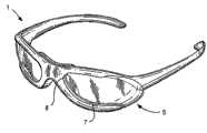
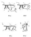
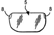
图1a是一副眼镜架和拆下的镜片的前视图,根据本发明第一实施例,镜架和镜片都包括磁体; Figure 1a is a front view of a pair of eyeglass frames and removed lenses, according to a first embodiment of the present invention, both the frame and the lenses include magnets;
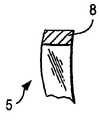
图1b是嵌入磁体或磁性材料的镜片的前视图; Figure 1b is a front view of a lens embedded with a magnet or magnetic material;
图1c是不带磁体或磁性材料的镜片的侧视图; Figure 1c is a side view of a lens without magnets or magnetic material;
图1d是镜片的前视图,其中,磁体或磁性材料固定于镜片,使所述磁体或磁性材料从镜片边缘伸出; Figure 1d is a front view of a lens with a magnet or magnetic material secured to the lens such that the magnet or magnetic material protrudes from the edge of the lens;
图2是如图1所示镜架的前视图,镜片安装在镜架上; Fig. 2 is the front view of the spectacle frame shown in Fig. 1, the eyeglass is installed on the spectacle frame;
图3a和图3b是图1和图2所示眼镜架在磁性安装点处的剖视图; Fig. 3 a and Fig. 3 b are the cross-sectional views of the spectacle frame shown in Fig. 1 and Fig. 2 at the magnetic mounting point;
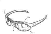
图4是带有磁性镜片的“叶片”式镜架的前视图; Figure 4 is a front view of a "blade" frame with magnetic lenses;
图5a至图5c是可选实施例的前视图,其中,磁体从镜片的顶部和鼻区伸出,装在镜架横臂和鼻托处带有磁性材料的凹处内; Figures 5a to 5c are front views of alternative embodiments in which magnets protrude from the top and nose regions of the lenses and are housed in recesses with magnetic material at the cross arms and nose pads of the frame;
图5d是T形磁性安装装置的剖视图,根据本发明另一个实施例所述,T形磁性安装装置从镜片伸出,并装在镜架的相应凹处 内; Figure 5d is a cross-sectional view of a T-shaped magnetic mounting device. According to another embodiment of the present invention, the T-shaped magnetic mounting device protrudes from the lens and is installed in a corresponding recess of the frame;
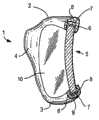
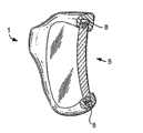
图6a是根据本发明又一实施例的一副眼镜架的轴测图; Figure 6a is an axonometric view of a pair of spectacle frames according to yet another embodiment of the present invention;
图6b是根据本发明又一实施例的镜片的轴测图; Figure 6b is an axonometric view of a lens according to yet another embodiment of the present invention;
图6c是图6a所示实施例中镜架和镜片的剖视图; Fig. 6c is the sectional view of spectacle frame and eyeglass in the embodiment shown in Fig. 6a;
图7是根据所有例示的实施例的眼镜架局部前视图,在包边中粘有磁体; Figure 7 is a partial front view of a spectacle frame according to all illustrated embodiments, with magnets glued in the edging;
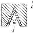
图8a至图8d是本发明不同实施例中磁体的剖视图,该磁体嵌入镜架的镜片包边的沟槽内; 8a to 8d are cross-sectional views of magnets in different embodiments of the present invention, the magnets are embedded in the grooves of the lens edge of the mirror frame;
图9a至图9d是磁体或磁性材料固定到不同镜片上的侧视图; Figures 9a to 9d are side views of magnets or magnetic materials fixed to different lenses;
图10a至图10b是本发明叶片式镜架实施例的前视图; Fig. 10a to Fig. 10b are the front views of blade type spectacle frame embodiment of the present invention;
图11a是本发明半包边式镜架实施例的前视图; Fig. 11a is the front view of the embodiment of semi-enclosed frame of the present invention;
图11b是根据图11a所示本发明又一实施例中局部包边的部分的侧视图; Fig. 11b is a side view of a part of partial hemming according to another embodiment of the present invention shown in Fig. 11a;
图11c是根据图11a所示本发明又一个实施例中镜片的前视图; Figure 11c is a front view of the eyeglass according to another embodiment of the present invention shown in Figure 11a;
图11d是根据图11c所示本发明又一个实施例中镜片的侧视图; Figure 11d is a side view of the lens according to another embodiment of the present invention shown in Figure 11c;
图11e是根据图11a所示本发明又一个实施例中镜片和局部包边的前视图; Fig. 11e is a front view of the lens and partial edging according to another embodiment of the present invention shown in Fig. 11a;
图12a至图12c’示出本发明三件式安装的实施例; Fig. 12a to Fig. 12c ' show the embodiment of three-piece installation of the present invention;
图13是本发明磁性包边锁紧闭合装置实施例的前视图; Figure 13 is a front view of an embodiment of a magnetic hemming locking closure device of the present invention;
图14a至图14c是本发明一种带有滑动销钉的实施例的前视图和侧视图; Fig. 14a to Fig. 14c are the front view and the side view of a kind of embodiment that has sliding pin of the present invention;
图15a至图15h是不同安装方法可使用的不同形状磁体的前视图和侧视图/剖视图; Figures 15a to 15h are front and side views/sectional views of magnets of different shapes that can be used with different mounting methods;
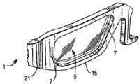
图16a是本发明一种实施例的轴测图,具有护目镜型镜架和两个护目罩型镜片; Figure 16a is an isometric view of an embodiment of the present invention having a goggle-type frame and two goggle-type lenses;
图16b是本发明一种实施例的剖视图,具有护目镜型镜架和两个护目罩型镜片; Figure 16b is a cross-sectional view of an embodiment of the present invention having a goggle-type frame and two goggle-type lenses;
图16c是可以和图16a所示实施例组合的一副镜片的前视图; Figure 16c is a front view of a pair of lenses that can be combined with the embodiment shown in Figure 16a;
图17a是镜片的前视图,框丝包围该镜片的边缘; Figure 17a is a front view of a lens with wire surrounding the edge of the lens;
图17b是镜片的前视图,框丝包围该镜片的边缘,并在该镜片中嵌有磁体或磁性材料; Figure 17b is a front view of the lens, the frame wire surrounds the edge of the lens, and a magnet or magnetic material is embedded in the lens;
图17c是框丝局部嵌入镜片边缘槽沟的轴测图;以及 Figure 17c is an axonometric view of the frame wire partially embedded in the edge groove of the lens; and
图17d是图17b所示镜片的俯视图。 Figure 17d is a top view of the lens shown in Figure 17b. the
具体实施方式Detailed ways
本文中的“镜片”应被理解为包括各种不同形状和尺寸的眼镜片,以及一个或多个护目罩型镜片。本文中的“镜架”应被理解为包括叶片式镜架、护目镜型镜架、常规镜架以及其它任何形式的眼镜架。本文中的“平光镜片”指不是按照配戴者的处方制成的镜片和护目罩。本文中的“处方镜片”是指按照配戴者的处方制成的镜片和护目罩。“平光镜片”和“处方镜片”在本文整个描述中是可以互换使用的。本文中的“磁体”、“磁性元件”、“磁化材料”和“磁性材料”是指磁体或具有磁性或能够吸引磁体的材料。本文中“磁体”、“磁性元件”、“磁化材料”和“磁性材料”是可以互换使用的。本文中的“磁性元件”是眼镜组件中的一个部件,是磁体或者由磁性吸引材料(magnetically attractive material)制成。本文中的“眼镜组件”是指组装到一起的一副眼镜,包括镜架和至少一个镜片。 "Lens" herein should be understood to include spectacle lenses of various shapes and sizes, as well as one or more goggle-type lenses. "Frames" herein should be understood to include leaf-type frames, goggle-type frames, conventional frames, and any other form of spectacle frames. As used herein, "plano lenses" refers to lenses and visors that are not made according to the wearer's prescription. As used herein, "prescription lenses" refers to lenses and eye shields made to the wearer's prescription. "Plan lens" and "prescription lens" are used interchangeably throughout the description herein. As used herein, "magnet", "magnetic element", "magnetized material" and "magnetic material" refer to a magnet or a material that is magnetic or capable of attracting a magnet. "Magnet", "magnetic element", "magnetizing material" and "magnetic material" are used interchangeably herein. A "magnetic element" in this context is a component in an eyeglass assembly that is a magnet or is made of a magnetically attractive material. An "eyeglass assembly" herein refers to a pair of eyeglasses assembled together, including a frame and at least one lens. the
图1(图1a至图1d)示出本发明的一个实施例。一副眼镜架1包括至少一块嵌在镜架1内的磁体或磁性吸引材料元件7。图1a中镜架1的每一侧都包括一段包边2和包边3,包边用于支撑镜片5。包边2和包边3的每一个均包括用于安装镜片5的凹部6。凹部6可以延伸至鼻托4。磁体或磁性吸引材料7嵌入镜架1中包边2和包边3的凹部6内。优选的是,镜架1中凹部6(用来安装镜片5)的每一侧上至少有一块磁体或磁性吸引材料7。具有反向吸引力的磁体或磁性材料8安装在镜片5的对应端处,当镜片5靠近镜架1时,通过相反极性磁体之间的吸引力,将镜片5的磁体8拉向镜架1的磁体 7。磁体7最好嵌入镜架1的凹部6内和每个镜片5的相应侧边9内。如图2所示,磁体的这种形式使得镜片完全就位,在磁力作用下,镜片固定在合适位置。 Figure 1 (Figures 1a-1d) shows an embodiment of the present invention. A pair of spectacle frames 1 includes at least one magnet or magnetically attracting
图1b示出嵌有磁体或磁性材料8的镜片。镜片5具有前表面10、后表面11和侧边9。图1c示出镜片5,后表面11朝下,侧边9正对读者,前表面10指向纸张顶部。图1c所示镜片5与图1b所示镜片相似,但图1c所示镜片5中没有嵌入磁体或磁性材料。在图1b所示镜片中,固定在镜片5上的磁体或磁性材料8与镜片5的侧面9齐平。磁体或磁性材料8可以与镜片5的前表面10或后表面11齐平。没有必要必须使磁体或磁性材料8与侧边9或前表面10或后表面11齐平或不齐平。只要在组装时,镜片上的磁体或磁性材料与镜架上的相应磁体或磁性材料足够靠近,使镜架和镜片上的磁体或磁性材料互相吸引,镜片就可以将磁体或磁性材料遮盖。 FIG. 1 b shows a lens with embedded magnets or
图1d示出根据本发明的另一镜片。磁体或磁性材料8从镜片5的侧边9突出。 Figure 1d shows another lens according to the invention. A magnet or
图2示出根据本发明一个实施例的前视图,示出装配好的眼镜架组件。镜架1中嵌有磁体或磁性材料7。镜片5中也嵌有磁体或磁性材料8。镜架的磁体或磁性材料7与镜片的磁体或磁性材料8之间的吸引力将镜片5固定到镜架1上。 Figure 2 illustrates a front view showing an assembled spectacle frame assembly according to one embodiment of the present invention. A magnet or a
图3a为剖视图,示出镜片5和镜架1之间的接触点。镜架1包括第一段包边2和第二段包边3。第一段包边2和第二段包边3具有用于安装镜片5的凹部6。凹部6的形状与镜片侧边的轮廓相一致。凹部6的代表性形状为U形,用来安装镜片5的端部。鼻托4上也可以具有凹部并且包括磁性材料。磁体或磁性材料8固定在镜片5的外侧,并且定位为靠近镜架1的磁体7。图3a示出眼镜的正面,镜片的前表面10正对着读者。在剖视图中,也可以看到镜片5的侧边9的位置。 FIG. 3 a is a cross-sectional view showing the point of contact between the
图3b示出图3a所示眼镜的剖视图,但第一磁体和第二磁体8嵌入镜片5内。磁性镜片5以隐藏方式(snugly)安装到镜架1上,防止镜架1在日常使用中意外脱落。 FIG. 3 b shows a cross-sectional view of the glasses shown in FIG. 3 a , but with the first and
在本发明的另一实施例中,磁体或磁性吸引材料可嵌入镜片内,以与镜片的侧面齐平。镜片可装于与图1至图3(图1a至图3b)所示凹部相似的凹部内,但镜片没有下包边部分。 In another embodiment of the invention, magnets or magnetically attracting material may be embedded in the lens so as to be flush with the sides of the lens. The lens can fit in a recess similar to that shown in Figures 1 to 3 (Figures 1a to 3b), but without the lower bezel. the
图4示出本发明的又一实施例。可将带有磁体或磁性材料的镜片5安装到“叶片”式镜架12上。“叶片”式镜架12是常规的翼形框设计,设计成没有为镜片5的下部弧形表面设置包边。换句话说,“叶片”式镜架看起来像一副镜片伸出一对翅膀。仅镜片5的上部和鼻子部分与镜架12接合。镜架12与镜片5的接触点包括:位于镜架12的横向桥接部47内的第一段凹部,以及,位于邻近鼻托4的侧壁内的第二段凹部。 Figure 4 shows yet another embodiment of the invention.
图5a示出本发明的又一实施例。如图4中所示,“叶片”型镜架12可将镜片5装在镜架12上包边部2的凹部6内,以及,装在靠近鼻托4的侧壁上的凹部6内。镜片5包括突起13,突起13从镜片5的侧边突出。磁体或磁性材料可以包括突起13,或者,磁体或磁性材料可安装于突起13上。 Figure 5a shows yet another embodiment of the invention. As shown in FIG. 4 , the “blade”
图5b与图5a示出本发明的同一个实施例,在图5b中,镜片放置到镜架上。镜架12中的磁体7位于镜架12的上包边部2和鼻托4的凹部内。镜片5放在镜架12中,使嵌入镜架的磁体或磁性材料7与嵌入镜片的磁体或磁性材料8的磁力能相互吸引。将镜片5向上插入镜架12的上包边部2中,位于用于安装突起的凹部内。一旦突起13被鼻区的磁体7牵拉到合适位置,通过第二磁体(嵌入镜架12上包边部2的凹部6内),将突起13向上拉到合适位置,此过程中产生轻微的机械止动,防止镜片5滑出槽沟6。 Fig. 5b shows the same embodiment of the invention as Fig. 5a, in Fig. 5b the lens is placed on the frame. The
如图5c所示,镜片5被放入镜架12上包边部2的凹部6内,并向鼻托4的方向滑动。一旦处于此位置,位于镜片5和镜架12内的相反极性磁体产生磁力,通过磁力将镜片5固定到镜架12上。另外,镜片5中的磁体锁在凹部6内,防止镜片5从“叶片”型镜架12脱落。 As shown in FIG. 5 c , the
图5d示出本发明的另一实施例。镜片5可包括一块磁体,该磁体位于镜片5中靠近鼻托4与镜架进行安装的部分处,并且在顶端具有一个机械的“T”形安装装置14。镜架12在其上包边部2和鼻托4中布置有磁体7。Figure 5d shows another embodiment of the invention. The
图6a至图6c示出本发明的另一实施例。镜架1包括围绕镜片5的全包边21。在本实施例中,镜片5必须从前部15或后部插入镜架,与图1至图3(图1a至图3b)所示实施例中镜片从侧面滑入镜架1的方式不同。在本发明此实施例中,镜架1没有沟槽-凹部,但具有台阶式的内表面22,如图6c所示,当插入镜片5时,该台阶式的内表面22为镜片5提供机械止动。此台阶可以是升起的后壁,使得镜片只能从镜架的前部移出。另外一种方式为台阶23可以是前壁,使得镜片5只能从镜架的后部移出。在此实施例中,镜片5在靠近侧边9处嵌有磁体8,镜片5插入镜架1(其中前壁或后壁升起)内,并定位成使得镜片5内的磁体8与镜架1内的磁体7对齐。镜片5相应地从前部或后部插入镜架,并通过镜架1和镜片5的磁体的磁力,将镜片5固定在合适位置。 Figures 6a to 6c show another embodiment of the invention. The
图7示出本发明的另一实施例。与前面所述实施例相似,磁体7可固定到眼镜架1上。磁体或磁性材料8也固定到镜片5上。镜架1的磁体或磁性材料7嵌入凹部内,使磁体或磁性材料7与镜架1的表面齐平。这样,镜片5安装到镜架1并与其齐平,同时,镜架1的磁体或磁性材料7与镜片5的磁体或磁性材料相互吸引固定。 Figure 7 shows another embodiment of the invention. Similar to the previously described embodiments, the
可选择地,镜架上的凹部不需要贯穿整个横梁的长度。如图1d所示的磁体,磁体从镜片边缘向外突出,并可装在镜架横梁的一个或多个凹部内。在此实施例中,与从镜片边缘伸出的磁体或磁性材料相对应,将磁体或磁性材料固定在镜架横梁的凹部内,此处凹部成形为适合于镜片突起的轮廓。然后,将镜片突起装配到镜架横梁的这些凹部内。 Optionally, the recess on the frame need not extend the entire length of the beam. As shown in Figure 1d, the magnets protrude outwardly from the edge of the lens and may fit within one or more recesses in the beam of the frame. In this embodiment, corresponding to the magnets or magnetic material protruding from the edge of the lens, the magnet or magnetic material is fixed in the recess of the frame beam, where the recess is shaped to fit the contour of the protrusion of the lens. The lens protrusions are then fitted into these recesses of the frame beam. the
图8a至图8d示出镜架凹部内的磁体分布。凹部可以是任何形状。图示出方形凹部26和三角形凹部16。在图8a中,矩形磁体7位于镜架1的方形凹部26内,使得凹部每侧都固定有磁体。图8b中,矩形磁体7位于方形凹部26的顶端。不需要使用矩形磁体。图8c示出将一个或多个三角形磁体18固定到具有三角形凹部16的镜架上。图8d示出三角形磁体18和三角形凹部16,三角形磁体18没有固定在三角形凹部16的全部表面上。 Figures 8a to 8d show the distribution of magnets in the recess of the frame. The recess can be of any shape. The figures show square recesses 26 and
本领域的技术人员容易理解,可采用很多方法形成包边上的凹部,以安装各种形状的镜片。还可以使用多种方法将磁体安装到这些不同形式的包边上。所述实施例不限于磁体的布置与包边凹部的组合。例如,本领域技术人员容易理解,镜架横梁可包括突出的磁体,或者,可包括固定有磁体或磁性材料的突起,镜片可包括带有磁体或磁性材料的凹部。 Those skilled in the art can easily understand that many methods can be used to form the concave portion on the wrapping so as to install lenses of various shapes. Magnets can also be attached to these different forms of binding using a variety of methods. The described embodiments are not limited to the arrangement of the magnets in combination with the edged recess. For example, those skilled in the art will readily understand that the beam of the frame may include protruding magnets, or may include protrusions on which magnets or magnetic materials are fixed, and the lenses may include recesses with magnets or magnetic materials. the
如图9a至图9d所示,磁体可固定到处方镜片或平光镜片上。图9a中,镜片5和磁体8具有相同的厚度,但固定到镜片上的磁体或磁性吸引材料可以比镜片更薄或更厚。此外,如图9b所示,磁体或磁性吸引材料可以是适合于放入镜片侧边的浅凹进内的薄片。 As shown in Figures 9a-9d, the magnets can be attached to prescription or plano lenses. In Fig. 9a, the
可将磁体8压配合到带有切口面的镜片5,例如图9c中镜片5。镜片5的切口面被压在镜片5上的磁体所遮盖,相应形成将镜片5安装到镜架上的面。如果需要,可以将具有相似形状的磁体安装到形状与此镜片相似的镜架上。 The
磁体可以位于镜架或凹部的任何侧面,并且可以是任何合适的形状。磁体8可以安装到具有弧形表面的镜片,例如图9a中的镜片5。磁体也可以安装到带有插口19的镜片上,使磁体从弧形表面突出,例如图9b中的镜片5。这两个实例中,磁体安装到镜片上的大致弧形部分,不是切口部分。优选的是,第一磁体安装于镜架的上表面,第二磁体安装为靠近鼻托的内表面。可将一块以上的磁体安装于镜片或镜架。 The magnets may be located on any side of the frame or recess and may be of any suitable shape. The
图10a示出本发明又一实施例的前视图。镜片5固定在镜架1上。镜片的磁体或磁性材料8与镜架的磁体或磁性材料7相互吸引。镜架的磁体或磁性材料7陷进镜架1的沟槽内,使得磁体或磁性材料与镜架1的表面和镜片5的顶端齐平。 Figure 10a shows a front view of yet another embodiment of the invention. The
图10b示出本发明又一实施例的前视图。镜片5被固定在镜片1上。镜片的磁体或磁性材料8与镜架的磁体或磁性材料7相互吸引。镜架的磁体或磁性材料7陷进镜架1的沟槽内,使得磁体 与镜架1的表面和镜片5的顶端齐平。镜片5上的插口46容纳于镜架1上具有相似形状的凹部内,并辅助将镜片5固定到镜架1上。 Figure 10b shows a front view of yet another embodiment of the invention. The
如图11a至图11e所示,另外一种形式眼镜架的有益结构为,磁性镜片5安装到带磁性表面的镜架上,这种眼镜架具有半包边镜架27。如图11a所示,镜架27具有典型的金属包边28,该金属包边具有与镜片5下半部分相对应的大致弧度表面。仅仅镜片5的下半部分和镜片5的部分侧面被镜架27包住。镜片5的其余部分(上部的大致弧形表面)不带包边。本领域的技术人员应该能理解本实施例并不局限于镜片的下部被镜架包覆,镜片其他部分(例如镜片的上半部分)也可以被镜架包覆。 As shown in FIGS. 11 a to 11 e , another form of spectacle frame is advantageous in that the
如图11b和图11c所示,为了将镜片5固定到半包边镜架27中,在朝向镜片5的拐角处,磁体7嵌在包边28的侧面29内。本领域技术人员容易理解,相似地,可以在包边28中环绕镜片5底部表面的部分内,嵌入磁体,并在镜片5的底部固定相应的磁体8,将镜片5安装到半包边上。如图11c所示,磁体或磁性材料8安装到镜片5的侧边9上,与镜架上的相应斜面相匹配,如图11b所示(方槽,大致V形槽,或圆形框丝)。这使得磁性镜片5与镜架27上的磁体或磁性材料7之间密切配合。图11b还示出,镜架27上的金属框丝或模制框丝(molded wire)典型结构为方槽、大致V形槽、或圆形的框丝。图11e是图11a所示镜片和半包边镜架拆开的前视图。 In order to fix the
图12a至图12c’示出本发明的另一实施例,其中,另一种磁性安装方式涉及三件式安装,也称为无包边式安装。三件式安装涉及一种不带包边或框丝的镜架结构。三件式安装包括三个部件:桥接杆32,镜腿或末端片31,以及镜片5。典型的无包边式安装包括:两个镜片5,通过连接到镜片5内侧边的桥接杆32,将这两个镜片5连接到一起;以及镜腿或末端片31,与镜片5外侧边相连。三件式安装装置中的磁体将三个部件互相结合。桥接杆32连接到镜片5的内拐角和/或内侧边,镜腿或末端片31连接到镜片5的外拐角或外侧边。 Figures 12a to 12c' show another embodiment of the present invention, wherein another magnetic mounting method involves a three-piece mounting, also known as a non-edging mounting. Three-piece mounting involves a frame construction without binding or wire. The three-piece mount consists of three parts:
图12a至图12b所示三件式安装的实施例中,镜片5固 定有磁体8,该磁体8安装于由各镜片5的第一和第二凹进30所限定的区域内,凹进30位于镜片5前表面和后表面上的内拐角和外拐角处。如图12a和图12b所示,磁体8直接置于第一凹进和第二凹进之间,朝向镜片的内层和外层,从而吸引框件的磁性表面7。 In the embodiment of the three-piece mounting shown in Figures 12a to 12b, the
图12b示出将镜片5安装到桥接杆32上的优选方法,桥接杆上固定有磁体33,磁体33位于桥接杆32的槽口48内,远离桥接杆32的侧边。通过桥接杆磁体33的磁力,将镜片内拐角处的相反极性磁体8拉向桥接杆磁体33,此时,槽口48会很好地紧挨着镜片5的内拐角。磁体彼此靠近时,磁体之间的吸引力增加,从而防止三件式安装松开。 Figure 12b shows a preferred method of mounting the
在三件式安装的另一个实施例中,沿着镜片的侧边,用金属环绕镜片5,仅在桥接杆32设置有至少一块磁体。在此实施例中,镜腿上没必要安装磁性元件。在另一个实施例中,桥接杆32可以是金属,镜片5安装有至少一块磁体。 In another embodiment of the three-piece mounting, the
如图12c所示,在每个镜腿或末端片和桥接杆32中靠近各镜片5外拐角或外侧边的第一端,镜腿或末端片和桥接杆32包括磁体或磁性材料33。连接在镜腿或末端片31或桥接杆32上的磁体伸向镜片5的外拐角,用来吸引嵌于镜片5内的相应磁体。此作用与桥接杆磁体与镜片5内拐角处磁体之间的作用相似。可以采用反向的不同设置,在镜片5后面设置磁体或突起,也能获得上述作用。 As shown in Figure 12c, at a first end of each temple or end piece and
如图12b所示,镜腿末端片31上的磁体或磁性材料33可位于末端片31的基部,朝向槽口48距离镜片5最远的一端。镜片5的磁体8安装于凹部中朝向末端片的最远端。镜片插入末端片后,磁体8和33相互牵拉,从而将镜片5固定在末端片31内。一种优选的结构是,可以布置在连接部位32和镜片部位30处。换句话说,磁体33位于凹部的上部或下部,朝向最靠近镜片5的第一端。 As shown in FIG. 12 b , the magnet or
如图13所示,本发明的另一个实施例是磁体包边锁紧闭合装置。在此安装方法中,在额杆相反侧的末端拐角处,磁体35固定在镜架34的包边36上。具体而言,磁体装于通常镜架34被锁紧的位置处,即包边锁紧的位置。这个位置也是镜腿37与包边36相连 的位置。本发明中,磁体代替螺钉作为锁紧件。常规的包边锁紧与本发明一样,其中,镜架的上部分和下部分在镜腿拐角处分开。传统的包边锁紧中,用螺钉连接上下两部分。在镜架的上部与下部结合的位置处,将磁体35施加于镜架34的末端。在磁性包边锁紧中,在此位置处不需要使用螺钉来锁定镜架34,因为磁力可以将镜架的两端连接在一起。由于磁体35连接至镜架的两端,这种磁性包边锁紧方法适用于任何合适形状的镜架,包括但不限于圆形或V形框丝。在本实施例中,镜片上不需要嵌入磁体。镜片可装在镜架34的包边凹部内,在包边锁紧装置闭合和磁性锁紧时,将镜片可靠地固定在合适位置。本领域技术人员容易理解,包边锁紧装置不仅可用在镜架的镜腿或末端片上,还可以用于镜架的鼻梁桥接部分。 As shown in Figure 13, another embodiment of the present invention is a magnetic edge lock closure device. In this mounting method,
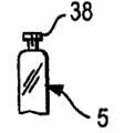
图14a至图14c示出本发明又一磁性安装方法的实施例,其中磁体与无磁性销钉38组合使用。如图14a所示,可以将无磁性销钉38安装到镜片上部的大致弧形表面。如图14c所示,销钉38安装在带有槽口39或沟槽的镜架1内。镜片5在其内表面上具有磁体8,磁体8靠近额杆,用于与嵌入镜架1的磁体相结合。如图14c所示,镜片5通过滑动销钉38固定到镜架1上,滑动销钉移入镜架1的槽口39,以固定镜片5。销钉38可以是大致T形销钉,镜片5位于镜架1上时,该T形销钉锁入到合适的位置。 Figures 14a to 14c show yet another embodiment of the magnetic mounting method of the present invention in which magnets are used in combination with
上述安装方法中所述的磁体或磁性吸引材料可以是本领域已知的任何适当的磁性材料,可以具有任何轮廓以及以任何方式成形。磁体通常质量较轻,能避免镜架过重给使用者增加负担。如图15a至图15h所示,磁体可以是任何形状,包括但不限于梯形(图15a)、矩形(图15b)、圆形(图15c)、月牙形(图15d)、方形(图15e)、V形(图15f)和三角形(图15g)。 The magnet or magnetically attracting material described in the above mounting method may be any suitable magnetic material known in the art, may have any profile and be shaped in any manner. The magnets are generally light in weight, which can prevent the frame from being too heavy and burdening the user. As shown in Figures 15a to 15h, the magnets can be of any shape, including but not limited to trapezoidal (Figure 15a), rectangular (Figure 15b), circular (Figure 15c), crescent (Figure 15d), square (Figure 15e) , V-shape (Fig. 15f) and triangle (Fig. 15g). the
在所有上述实施例中,磁体或磁性吸引材料可以嵌入镜片和镜架、用胶粘入镜片或镜架、压进镜片和镜架或与镜片和镜架过盈配合、或以其他任何适当的方式装配到镜片和镜架上。 In all of the above embodiments, the magnet or magnetically attracting material may be embedded in the lens and frame, glued into the lens or frame, pressed into or interference fit with the lens and frame, or in any other suitable manner. way to assemble to the lens and frame. the
此外,如图15h所示,磁体可装到沟槽或凹部内,以与相对的磁性表面相结合。也可以将磁体作为施加约束性物质(诸如胶) 的表面,从而将磁体固定到镜片或镜架上。 Additionally, as shown in Figure 15h, magnets may be fitted into grooves or recesses to engage opposing magnetic surfaces. Magnets can also be used as a surface to which a binding substance such as glue is applied to secure the magnet to the lens or frame. the
图16a示出本发明用在护目镜的实施例。磁体或磁性材料部件8固定到护目罩型镜片40内,该护目罩型镜片40适合于安装到护目镜型镜架41中。在护目镜型镜架41上固定极性相反的磁体或磁性材料7。相反极性的磁体或磁性材料7布置为,使得在将镜片40安装到镜架41上时,护目罩型镜片的磁体或磁性材料8与镜架41的磁体或磁性材料7对齐。磁体之间或磁体与磁性材料之间的相互吸引力将镜片连接到镜架上。本领域技术人员容易理解,在镜架41的槽沟或凹部6内固定磁体7有助于将镜片固定到镜架41上。如图16b所示,槽沟或凹部6的尺寸能可靠地安装镜片,从而将镜片固定在合适位置。图16b示出护目镜架的剖视图,在镜架中装有双层镜片。 Figure 16a shows an embodiment of the invention applied to goggles. A magnet or
图16a示出,磁体或磁性材料8固定到护目罩型镜片40的侧面,本领域技术人员容易理解,磁体或磁性材料可以固定到护目罩型镜片40的任何部位,只要镜片中磁体或磁性材料的固定位置与镜架中磁体或磁性材料的固定位置相对应即可。本领域技术人员容易理解,除了护目罩型镜片,通过使用根据本发明的磁体,还可以将其他形式的镜片固定到护目镜型镜架内。图16c示出这种类型镜片的另一实施例。本领域技术人员容易理解,可以使用或不使用磁体,将一个镜片(任何形式的镜片)永久安装到镜架上,以及,可以使用根据本发明的磁体,将另一个镜片(任何形式的镜片)以可拆卸方式安装到同一镜架上。可能需要将护目罩型镜片和常规形状镜片组合用在护目镜型镜架中。 Figure 16a shows that the magnet or
图17a示出本发明的又一实施例。由位于镜片5的侧边9上的框42环绕镜片5。框丝42可用作磁性材料,在镜架上固定至少一块磁体,而镜片上不设置磁体,从而实现将镜片结合到镜架上。如图17b和图17d所示,在另一可选实施例中,框42也可以包覆在磁性元件的顶部,以将磁性元件8固定在镜片5内。图17b是本发明的另一个实施例。框丝42环绕镜片5。磁体或磁性材料8嵌入镜片5内。在要安装镜片的镜架上,固定有极性相反的磁体或磁性材料。镜架的相反极性磁体或磁性材料布置为,使得当镜片装入镜架后,镜 片的磁体或磁性材料8与镜架中的磁体对齐。磁体之间或磁体与磁性材料之间的吸引力将镜片与镜架结合起来。本领域技术人员容易理解,框丝42也可以嵌入镜片的槽沟内,如图17c所示。本领域技术人员还容易理解,框丝也可嵌入镜架中,从而,在将镜片固定到镜架时有助于增强磁吸力。 Figure 17a shows yet another embodiment of the invention. The
虽然本发明根据其特定的具体实施例加以描述,但是对于本领域技术人员来说,可以容易地对上述实施方案进行多种修改和改进,而不偏离本发明的目的、精神和范围。所有这些改动均在本发明权利要求范围内。 Although the present invention has been described in terms of specific embodiments thereof, those skilled in the art can easily make various modifications and improvements to the above-described embodiments without departing from the purpose, spirit and scope of the present invention. All these modifications are within the scope of the claims of the present invention. the
Claims (9)
Translated fromChineseApplications Claiming Priority (3)
| Application Number | Priority Date | Filing Date | Title |
|---|---|---|---|
| US75856206P | 2006-01-13 | 2006-01-13 | |
| US60/758,562 | 2006-01-13 | ||
| PCT/US2007/000681WO2007084311A2 (en) | 2006-01-13 | 2007-01-11 | Eyewear frames with magnetic lens attachments |
Publications (2)
| Publication Number | Publication Date |
|---|---|
| CN101384946A CN101384946A (en) | 2009-03-11 |
| CN101384946Btrue CN101384946B (en) | 2011-05-11 |
Family
ID=38288106
Family Applications (1)
| Application Number | Title | Priority Date | Filing Date |
|---|---|---|---|
| CN2007800056151AExpired - Fee RelatedCN101384946B (en) | 2006-01-13 | 2007-01-11 | Spectacle frame with magnetic lens mount |
Country Status (8)
| Country | Link |
|---|---|
| US (1) | US7850301B2 (en) |
| EP (1) | EP1971893A4 (en) |
| JP (1) | JP2009524081A (en) |
| CN (1) | CN101384946B (en) |
| AU (1) | AU2007207830B2 (en) |
| CA (1) | CA2636895C (en) |
| TW (1) | TWI388894B (en) |
| WO (1) | WO2007084311A2 (en) |
Cited By (1)
| Publication number | Priority date | Publication date | Assignee | Title |
|---|---|---|---|---|
| WO2025114956A1 (en) | 2023-11-30 | 2025-06-05 | Juan Manuel Castro | Magnetic spectacles with removable frames |
Families Citing this family (116)
| Publication number | Priority date | Publication date | Assignee | Title |
|---|---|---|---|---|
| US8092007B2 (en)* | 2006-01-13 | 2012-01-10 | Switch Vision, Llc | Eyewear frames with magnetic lens attachments |
| US20130271722A1 (en)* | 2006-01-13 | 2013-10-17 | Switch Vision, Llc | Eyewear frames with magnetic lens attachments |
| US8641188B2 (en)* | 2006-01-13 | 2014-02-04 | Switch Vision, Llc | Eyewear frames with magnetic lens attachments |
| US7866816B2 (en)* | 2006-10-10 | 2011-01-11 | Lane Research, Llc | Variable focus spectacles |
| US9158116B1 (en) | 2014-04-25 | 2015-10-13 | Osterhout Group, Inc. | Temple and ear horn assembly for headworn computer |
| ITPD20080029A1 (en)* | 2008-01-25 | 2009-07-26 | Rudy Project S R L | GLASSES WITH INTERCHANGEABLE LENSES |
| US7712895B2 (en)* | 2008-01-30 | 2010-05-11 | Chih-Hung Wang | Eyeglasses structure |
| FR2929018B1 (en)* | 2008-03-21 | 2010-07-30 | Chih Ming Chen | LIGHTWEIGHT ARTICLE WITH MAGNETIC CONNECTION OF TWO GLASSES TO A FRAME |
| CN102067013B (en) | 2008-07-03 | 2016-02-10 | 奥克利有限公司 | floating lens mounting system |
| US9298007B2 (en) | 2014-01-21 | 2016-03-29 | Osterhout Group, Inc. | Eye imaging in head worn computing |
| US9229233B2 (en) | 2014-02-11 | 2016-01-05 | Osterhout Group, Inc. | Micro Doppler presentations in head worn computing |
| US9400390B2 (en) | 2014-01-24 | 2016-07-26 | Osterhout Group, Inc. | Peripheral lighting for head worn computing |
| US9952664B2 (en) | 2014-01-21 | 2018-04-24 | Osterhout Group, Inc. | Eye imaging in head worn computing |
| US9965681B2 (en) | 2008-12-16 | 2018-05-08 | Osterhout Group, Inc. | Eye imaging in head worn computing |
| US20150205111A1 (en) | 2014-01-21 | 2015-07-23 | Osterhout Group, Inc. | Optical configurations for head worn computing |
| US9715112B2 (en) | 2014-01-21 | 2017-07-25 | Osterhout Group, Inc. | Suppression of stray light in head worn computing |
| US8469510B2 (en) | 2009-01-09 | 2013-06-25 | Oakley, Inc. | Eyewear with enhanced ballistic resistance |
| DE102009043735A1 (en)* | 2009-10-01 | 2011-04-14 | Christian Leistritz | Additional pair of eyeglasses with fasteners |
| WO2011041733A1 (en) | 2009-10-02 | 2011-04-07 | Oakley, Inc. | Eyeglass with interchangeable ornamentation |
| JP5309060B2 (en)* | 2010-03-09 | 2013-10-09 | ミドリ安全株式会社 | Work glasses |
| US8371905B1 (en)* | 2010-03-10 | 2013-02-12 | Zoom Focus Eyewear, LLC | Magnetically attached spectacle lens with hidden magnets and method |
| AU2011227042B2 (en) | 2010-03-19 | 2014-03-06 | Oakley, Inc. | Goggle |
| US8668330B2 (en) | 2010-08-13 | 2014-03-11 | Oakley, Inc. | Eyewear with lens retention mechanism |
| US8313191B2 (en) | 2010-10-15 | 2012-11-20 | Miro Optix Llc | Eyewear assembly |
| US8517533B2 (en) | 2010-12-17 | 2013-08-27 | Mark Razin | Eyewear with removeable secured adjustable strap |
| CA3073389C (en) | 2011-06-24 | 2022-09-06 | Marchon Eyewear, Inc. | Sports goggle |
| US9188792B2 (en) | 2011-09-22 | 2015-11-17 | Oakley, Inc. | Mounting mechanism for eyewear |
| US9122078B2 (en) | 2011-12-01 | 2015-09-01 | Oakley, Inc. | Releasable earstem mounting mechanism for eyewear |
| JP4929420B1 (en)* | 2011-12-21 | 2012-05-09 | 一成 大浦 | Auxiliary lens fitting glasses |
| US20130185849A1 (en)* | 2012-01-24 | 2013-07-25 | The Burton Corporation | Magnetic goggle lens attachment |
| US8960420B2 (en) | 2012-03-09 | 2015-02-24 | Switch Vision Llc | Lens pod |
| US9104043B2 (en) | 2012-03-09 | 2015-08-11 | Switch Vision Llc | Detachable lenses for eyewear |
| USD725177S1 (en) | 2012-03-19 | 2015-03-24 | Switch Vision Llc | Eyewear |
| US9291823B2 (en)* | 2012-03-30 | 2016-03-22 | Google Inc. | Wearable device with input and output structures |
| TWI563313B (en)* | 2012-05-30 | 2016-12-21 | Ags Global Marketing Inc | Eyeglasses |
| US9241833B2 (en) | 2012-08-31 | 2016-01-26 | Oakley, Inc. | Eyewear having multiple ventilation states |
| JP6221223B2 (en)* | 2012-11-16 | 2017-11-01 | セイコーエプソン株式会社 | Optical member and virtual image display device |
| WO2014093514A1 (en) | 2012-12-11 | 2014-06-19 | Oakley, Inc. | Eyewear with outriggers |
| CN102981286A (en)* | 2012-12-12 | 2013-03-20 | 江苏快信光学科技有限公司 | Sunglasses with detachably replaced lenses |
| TW201439637A (en)* | 2013-02-13 | 2014-10-16 | Planet Vision 60 Co Ltd | Glasses |
| ITPD20130036A1 (en)* | 2013-02-13 | 2014-08-14 | Vito Rinaldo | GLASSES WITH COMBINED FRAMES |
| WO2014138159A1 (en) | 2013-03-07 | 2014-09-12 | Oakley, Inc. | Regeneratable ant-fogging element for goggle |
| CH708683B1 (en)* | 2013-10-15 | 2018-01-15 | Tolotto Heinz | Modular kit for individually configurable assembly of a pair of glasses as well as spectacles assembled from it. |
| US11227294B2 (en) | 2014-04-03 | 2022-01-18 | Mentor Acquisition One, Llc | Sight information collection in head worn computing |
| US9671613B2 (en) | 2014-09-26 | 2017-06-06 | Osterhout Group, Inc. | See-through computer display systems |
| US9841599B2 (en) | 2014-06-05 | 2017-12-12 | Osterhout Group, Inc. | Optical configurations for head-worn see-through displays |
| US10191279B2 (en) | 2014-03-17 | 2019-01-29 | Osterhout Group, Inc. | Eye imaging in head worn computing |
| US9299194B2 (en) | 2014-02-14 | 2016-03-29 | Osterhout Group, Inc. | Secure sharing in head worn computing |
| US9529195B2 (en) | 2014-01-21 | 2016-12-27 | Osterhout Group, Inc. | See-through computer display systems |
| US9594246B2 (en) | 2014-01-21 | 2017-03-14 | Osterhout Group, Inc. | See-through computer display systems |
| US20160019715A1 (en) | 2014-07-15 | 2016-01-21 | Osterhout Group, Inc. | Content presentation in head worn computing |
| US9810906B2 (en) | 2014-06-17 | 2017-11-07 | Osterhout Group, Inc. | External user interface for head worn computing |
| US10254856B2 (en) | 2014-01-17 | 2019-04-09 | Osterhout Group, Inc. | External user interface for head worn computing |
| US20150277118A1 (en) | 2014-03-28 | 2015-10-01 | Osterhout Group, Inc. | Sensor dependent content position in head worn computing |
| US9746686B2 (en) | 2014-05-19 | 2017-08-29 | Osterhout Group, Inc. | Content position calibration in head worn computing |
| US9939934B2 (en) | 2014-01-17 | 2018-04-10 | Osterhout Group, Inc. | External user interface for head worn computing |
| US9575321B2 (en) | 2014-06-09 | 2017-02-21 | Osterhout Group, Inc. | Content presentation in head worn computing |
| US11103122B2 (en) | 2014-07-15 | 2021-08-31 | Mentor Acquisition One, Llc | Content presentation in head worn computing |
| US10684687B2 (en) | 2014-12-03 | 2020-06-16 | Mentor Acquisition One, Llc | See-through computer display systems |
| US10649220B2 (en) | 2014-06-09 | 2020-05-12 | Mentor Acquisition One, Llc | Content presentation in head worn computing |
| US9829707B2 (en) | 2014-08-12 | 2017-11-28 | Osterhout Group, Inc. | Measuring content brightness in head worn computing |
| US20150205135A1 (en) | 2014-01-21 | 2015-07-23 | Osterhout Group, Inc. | See-through computer display systems |
| US9740280B2 (en) | 2014-01-21 | 2017-08-22 | Osterhout Group, Inc. | Eye imaging in head worn computing |
| US12105281B2 (en) | 2014-01-21 | 2024-10-01 | Mentor Acquisition One, Llc | See-through computer display systems |
| US9651784B2 (en) | 2014-01-21 | 2017-05-16 | Osterhout Group, Inc. | See-through computer display systems |
| US12093453B2 (en) | 2014-01-21 | 2024-09-17 | Mentor Acquisition One, Llc | Eye glint imaging in see-through computer display systems |
| US9615742B2 (en) | 2014-01-21 | 2017-04-11 | Osterhout Group, Inc. | Eye imaging in head worn computing |
| US11669163B2 (en) | 2014-01-21 | 2023-06-06 | Mentor Acquisition One, Llc | Eye glint imaging in see-through computer display systems |
| US9753288B2 (en) | 2014-01-21 | 2017-09-05 | Osterhout Group, Inc. | See-through computer display systems |
| US9651788B2 (en) | 2014-01-21 | 2017-05-16 | Osterhout Group, Inc. | See-through computer display systems |
| US11487110B2 (en) | 2014-01-21 | 2022-11-01 | Mentor Acquisition One, Llc | Eye imaging in head worn computing |
| US9836122B2 (en) | 2014-01-21 | 2017-12-05 | Osterhout Group, Inc. | Eye glint imaging in see-through computer display systems |
| US9766463B2 (en) | 2014-01-21 | 2017-09-19 | Osterhout Group, Inc. | See-through computer display systems |
| US11737666B2 (en) | 2014-01-21 | 2023-08-29 | Mentor Acquisition One, Llc | Eye imaging in head worn computing |
| US9494800B2 (en) | 2014-01-21 | 2016-11-15 | Osterhout Group, Inc. | See-through computer display systems |
| US11892644B2 (en) | 2014-01-21 | 2024-02-06 | Mentor Acquisition One, Llc | See-through computer display systems |
| US9811152B2 (en) | 2014-01-21 | 2017-11-07 | Osterhout Group, Inc. | Eye imaging in head worn computing |
| US9846308B2 (en) | 2014-01-24 | 2017-12-19 | Osterhout Group, Inc. | Haptic systems for head-worn computers |
| US9401540B2 (en) | 2014-02-11 | 2016-07-26 | Osterhout Group, Inc. | Spatial location presentation in head worn computing |
| WO2015148770A1 (en) | 2014-03-27 | 2015-10-01 | Oakley, Inc. | Mounting mechanism for eyewear |
| US20160187651A1 (en) | 2014-03-28 | 2016-06-30 | Osterhout Group, Inc. | Safety for a vehicle operator with an hmd |
| US9423842B2 (en) | 2014-09-18 | 2016-08-23 | Osterhout Group, Inc. | Thermal management for head-worn computer |
| US20150309534A1 (en) | 2014-04-25 | 2015-10-29 | Osterhout Group, Inc. | Ear horn assembly for headworn computer |
| US9672210B2 (en) | 2014-04-25 | 2017-06-06 | Osterhout Group, Inc. | Language translation with head-worn computing |
| US10853589B2 (en) | 2014-04-25 | 2020-12-01 | Mentor Acquisition One, Llc | Language translation with head-worn computing |
| US9651787B2 (en) | 2014-04-25 | 2017-05-16 | Osterhout Group, Inc. | Speaker assembly for headworn computer |
| US10663740B2 (en) | 2014-06-09 | 2020-05-26 | Mentor Acquisition One, Llc | Content presentation in head worn computing |
| USD740350S1 (en)* | 2014-07-31 | 2015-10-06 | Roger Wen Yi Hsu | Eyewear apparatus |
| USD752679S1 (en)* | 2014-09-15 | 2016-03-29 | Michele W. Smith | Eyeglasses |
| US9684172B2 (en) | 2014-12-03 | 2017-06-20 | Osterhout Group, Inc. | Head worn computer display systems |
| CN104460028A (en)* | 2014-12-15 | 2015-03-25 | 马单 | Glasses with replaceable glasses lenses |
| USD751552S1 (en) | 2014-12-31 | 2016-03-15 | Osterhout Group, Inc. | Computer glasses |
| USD753114S1 (en) | 2015-01-05 | 2016-04-05 | Osterhout Group, Inc. | Air mouse |
| US20160239985A1 (en) | 2015-02-17 | 2016-08-18 | Osterhout Group, Inc. | See-through computer display systems |
| US10687981B2 (en) | 2015-10-09 | 2020-06-23 | Oakley, Inc. | Headworn supports with passive venting and removable lens |
| US9709817B2 (en) | 2015-12-07 | 2017-07-18 | Oakley, Inc. | Eyewear retention devices and methods |
| EP3387485B1 (en) | 2015-12-08 | 2025-05-07 | Oakley, Inc. | Eyewear traction devices and methods |
| US9880441B1 (en) | 2016-09-08 | 2018-01-30 | Osterhout Group, Inc. | Electrochromic systems for head-worn computer systems |
| CN205388668U (en)* | 2016-03-16 | 2016-07-20 | 王道敏 | Myopia sunglasses |
| US10684478B2 (en) | 2016-05-09 | 2020-06-16 | Mentor Acquisition One, Llc | User interface systems for head-worn computers |
| US10466491B2 (en) | 2016-06-01 | 2019-11-05 | Mentor Acquisition One, Llc | Modular systems for head-worn computers |
| US10824253B2 (en) | 2016-05-09 | 2020-11-03 | Mentor Acquisition One, Llc | User interface systems for head-worn computers |
| US10359642B2 (en) | 2016-04-22 | 2019-07-23 | Oakley, Inc. | Mounting mechanism for eyewear |
| ES2592821B2 (en)* | 2016-06-30 | 2017-06-21 | Pedro Claverias Torres | INTERCHANGEABLE LENSES MULTIPLE GLASSES |
| US10690936B2 (en) | 2016-08-29 | 2020-06-23 | Mentor Acquisition One, Llc | Adjustable nose bridge assembly for headworn computer |
| USD840395S1 (en) | 2016-10-17 | 2019-02-12 | Osterhout Group, Inc. | Head-worn computer |
| USD864959S1 (en) | 2017-01-04 | 2019-10-29 | Mentor Acquisition One, Llc | Computer glasses |
| JP2019082531A (en)* | 2017-10-30 | 2019-05-30 | ソニー株式会社 | Head-mounted display |
| WO2019198875A1 (en) | 2018-04-13 | 2019-10-17 | 임성규 | Self-customized glasses |
| US10620451B1 (en)* | 2018-05-15 | 2020-04-14 | Nancy T. Kirsch | Eyeglasses with removable lens |
| US11925582B2 (en) | 2019-09-09 | 2024-03-12 | Gateway Safety, Inc. | Metal-detectable lens assemblies and protective eyewear including same |
| US11590027B2 (en) | 2019-09-09 | 2023-02-28 | Gateway Safety, Inc. | Metal-detectable lens assemblies and protective eyewear including same |
| JP7437042B2 (en)* | 2021-07-02 | 2024-02-22 | 株式会社ジンズホールディングス | Eyewear and front desk |
| USD1051978S1 (en) | 2021-11-02 | 2024-11-19 | Lucyd, Ltd. | Safety shield |
| KR102788112B1 (en)* | 2022-02-24 | 2025-03-31 | 주식회사 화이트 | Magnetic Glasses That Are Easy To Replace |
| WO2025136600A1 (en)* | 2023-12-20 | 2025-06-26 | Fgx International, Inc | Eyewear system with replaceable lenses |
Citations (3)
| Publication number | Priority date | Publication date | Assignee | Title |
|---|---|---|---|---|
| US3838914A (en)* | 1973-06-08 | 1974-10-01 | F Fernandez | Eyeglass with replaceable lens |
| JPS5972417A (en) | 1982-10-19 | 1984-04-24 | Fujita Shoji:Kk | Frame of spectacles |
| US6592220B1 (en)* | 2002-01-30 | 2003-07-15 | Lak Cheong | Eyeglass frame with removably mounted lenses |
Family Cites Families (12)
| Publication number | Priority date | Publication date | Assignee | Title |
|---|---|---|---|---|
| DE1951702U (en)* | 1965-10-22 | 1966-12-15 | Charles Henri Martin | BRACKET FOR EYE GLASSES. |
| FR2020976A1 (en) | 1968-10-18 | 1970-07-17 | Union Carbide Corp | Laser head cooling system |
| GB2199155A (en)* | 1986-09-22 | 1988-06-29 | Morris Goldschmidt | Spectacles with manually replaceable lenses having split rims |
| JPH087848Y2 (en)* | 1991-01-30 | 1996-03-06 | 株式会社アックス | Double lens goggles |
| US5321442A (en)* | 1992-02-25 | 1994-06-14 | Albanese Gerry M | Eyeglasses with detachable lenses, sidebars, and adjustable earpieces |
| JPH0734421U (en)* | 1993-12-03 | 1995-06-23 | 日新工機株式会社 | Eye mirror |
| EP1209509A1 (en)* | 2000-09-02 | 2002-05-29 | Hans Jürgen Gers | Spectacles with removable lenses |
| US6478420B2 (en)* | 2002-03-07 | 2002-11-12 | Ycc Optical Manufacturer | Magnetic spectacles |
| JP2004021086A (en)* | 2002-06-19 | 2004-01-22 | Fukui Craft:Kk | Lens attachable/detachable glasses |
| US7140727B2 (en) | 2002-07-10 | 2006-11-28 | Isl Technologies, Llc | Eyeglass frame assembly |
| FR2867573B1 (en)* | 2004-03-15 | 2006-09-29 | Charles Ayache | MAGNETIC ASSEMBLY GLASSES GLASSES |
| EP1971896B1 (en)* | 2005-07-18 | 2016-11-02 | Chemistrie Properties, Inc. | Attachable magnetic eyeglasses and its manufacturing |
- 2007
- 2007-01-11JPJP2008550389Apatent/JP2009524081A/enactivePending
- 2007-01-11CNCN2007800056151Apatent/CN101384946B/ennot_activeExpired - Fee Related
- 2007-01-11EPEP20070718216patent/EP1971893A4/ennot_activeWithdrawn
- 2007-01-11AUAU2007207830Apatent/AU2007207830B2/ennot_activeCeased
- 2007-01-11USUS11/658,390patent/US7850301B2/enactiveActive
- 2007-01-11CACA2636895Apatent/CA2636895C/enactiveActive
- 2007-01-11WOPCT/US2007/000681patent/WO2007084311A2/enactiveApplication Filing
- 2007-01-12TWTW096101297Apatent/TWI388894B/ennot_activeIP Right Cessation
Patent Citations (3)
| Publication number | Priority date | Publication date | Assignee | Title |
|---|---|---|---|---|
| US3838914A (en)* | 1973-06-08 | 1974-10-01 | F Fernandez | Eyeglass with replaceable lens |
| JPS5972417A (en) | 1982-10-19 | 1984-04-24 | Fujita Shoji:Kk | Frame of spectacles |
| US6592220B1 (en)* | 2002-01-30 | 2003-07-15 | Lak Cheong | Eyeglass frame with removably mounted lenses |
Cited By (1)
| Publication number | Priority date | Publication date | Assignee | Title |
|---|---|---|---|---|
| WO2025114956A1 (en) | 2023-11-30 | 2025-06-05 | Juan Manuel Castro | Magnetic spectacles with removable frames |
Also Published As
| Publication number | Publication date |
|---|---|
| EP1971893A2 (en) | 2008-09-24 |
| AU2007207830A1 (en) | 2007-07-26 |
| CA2636895C (en) | 2014-03-11 |
| JP2009524081A (en) | 2009-06-25 |
| TW200734714A (en) | 2007-09-16 |
| WO2007084311A3 (en) | 2007-11-22 |
| US7850301B2 (en) | 2010-12-14 |
| CA2636895A1 (en) | 2007-07-26 |
| WO2007084311A2 (en) | 2007-07-26 |
| US20090257019A1 (en) | 2009-10-15 |
| AU2007207830B2 (en) | 2012-03-01 |
| CN101384946A (en) | 2009-03-11 |
| TWI388894B (en) | 2013-03-11 |
| HK1127645A1 (en) | 2009-10-02 |
| EP1971893A4 (en) | 2009-12-09 |
Similar Documents
| Publication | Publication Date | Title |
|---|---|---|
| CN101384946B (en) | Spectacle frame with magnetic lens mount | |
| US8092007B2 (en) | Eyewear frames with magnetic lens attachments | |
| CN100465701C (en) | Auxiliary lenses for magnetic attachment of eyeglasses | |
| US6592220B1 (en) | Eyeglass frame with removably mounted lenses | |
| US6834951B2 (en) | Spectacles set with detachable magnetic shelter frame | |
| US20050105041A1 (en) | Interchangeable eyewear assembly | |
| CN102246087A (en) | Spectacle frame with replaceable lenses held by magnetic closure and system for replaceable lenses | |
| KR100597298B1 (en) | Clip hinged glasses | |
| US7370961B2 (en) | Interchangeable eyewear assembly | |
| US8480226B2 (en) | Frame construction for eyewear | |
| US9104043B2 (en) | Detachable lenses for eyewear | |
| US20060256280A1 (en) | Eyeframe with interchangeable lenspieces held by magnetic closure and interchangeable lens system | |
| US6382787B1 (en) | Spectacles set with a detachable sunglasses for mounting on a primary spectacle frame by means of magnetic attraction and interlocking engagement | |
| US6412941B1 (en) | Fully-cover shelter frame | |
| US20130271722A1 (en) | Eyewear frames with magnetic lens attachments | |
| US6540348B1 (en) | Spectacles set with detachable shelter frame | |
| CN103984115A (en) | Glasses | |
| AU2017293435B2 (en) | Eyeglasses with easy snap-on lenses | |
| JP2007279495A (en) | Front-hung spectacles | |
| HK1127645B (en) | Eyewear frames with magnetic lens attachments | |
| US20080013039A1 (en) | Interchangeable eyewear assembly | |
| WO2006043941A1 (en) | Interchangeable eyewear assembly | |
| WO2003016987A1 (en) | Clip on eyeware |
Legal Events
| Date | Code | Title | Description |
|---|---|---|---|
| C06 | Publication | ||
| PB01 | Publication | ||
| C10 | Entry into substantive examination | ||
| SE01 | Entry into force of request for substantive examination | ||
| REG | Reference to a national code | Ref country code:HK Ref legal event code:DE Ref document number:1127645 Country of ref document:HK | |
| C14 | Grant of patent or utility model | ||
| GR01 | Patent grant | ||
| REG | Reference to a national code | Ref country code:HK Ref legal event code:GR Ref document number:1127645 Country of ref document:HK | |
| ASS | Succession or assignment of patent right | Owner name:YINGBIAN LTD. Free format text:FORMER OWNER: LIBERTY SPORT INC. Effective date:20120612 | |
| C41 | Transfer of patent application or patent right or utility model | ||
| TR01 | Transfer of patent right | Effective date of registration:20120612 Address after:New jersey, USA Patentee after:Shadow Change Co.,Ltd. Address before:New jersey, USA Patentee before:LIBERTY SPORT, Inc. | |
| CF01 | Termination of patent right due to non-payment of annual fee | Granted publication date:20110511 | |
| CF01 | Termination of patent right due to non-payment of annual fee |