CN101384936A - Fiber distribution hub with outside accessible grounding terminals - Google Patents
Fiber distribution hub with outside accessible grounding terminalsDownload PDFInfo
- Publication number
- CN101384936A CN101384936ACNA2007800051872ACN200780005187ACN101384936ACN 101384936 ACN101384936 ACN 101384936ACN A2007800051872 ACNA2007800051872 ACN A2007800051872ACN 200780005187 ACN200780005187 ACN 200780005187ACN 101384936 ACN101384936 ACN 101384936A
- Authority
- CN
- China
- Prior art keywords
- panel
- cable
- ground
- distribution hub
- chassis
- Prior art date
- Legal status (The legal status is an assumption and is not a legal conclusion. Google has not performed a legal analysis and makes no representation as to the accuracy of the status listed.)
- Granted
Links
Images


Classifications
- G—PHYSICS
- G02—OPTICS
- G02B—OPTICAL ELEMENTS, SYSTEMS OR APPARATUS
- G02B6/00—Light guides; Structural details of arrangements comprising light guides and other optical elements, e.g. couplings
- G02B6/44—Mechanical structures for providing tensile strength and external protection for fibres, e.g. optical transmission cables
- G02B6/4439—Auxiliary devices
- G02B6/444—Systems or boxes with surplus lengths
- G02B6/4452—Distribution frames
- G02B6/44526—Panels or rackmounts covering a whole width of the frame or rack
- G—PHYSICS
- G02—OPTICS
- G02B—OPTICAL ELEMENTS, SYSTEMS OR APPARATUS
- G02B6/00—Light guides; Structural details of arrangements comprising light guides and other optical elements, e.g. couplings
- G02B6/44—Mechanical structures for providing tensile strength and external protection for fibres, e.g. optical transmission cables
- G02B6/4439—Auxiliary devices
- G02B6/444—Systems or boxes with surplus lengths
- G02B6/44528—Patch-cords; Connector arrangements in the system or in the box
- G—PHYSICS
- G02—OPTICS
- G02B—OPTICAL ELEMENTS, SYSTEMS OR APPARATUS
- G02B6/00—Light guides; Structural details of arrangements comprising light guides and other optical elements, e.g. couplings
- G02B6/46—Processes or apparatus adapted for installing or repairing optical fibres or optical cables
Landscapes
- Physics & Mathematics (AREA)
- General Physics & Mathematics (AREA)
- Optics & Photonics (AREA)
- Light Guides In General And Applications Therefor (AREA)
Abstract
Translated fromChinese
Description
Translated fromChinese相关申请related application
本申请要求2006年3月17日递交的美国临时专利申请号60/783,818的优先权,并且是2006年2月13日提出的美国专利申请号11/354,286的部分连续案,这里将该申请完整引入本文作为参考。This application claims priority to U.S. Provisional Patent Application No. 60/783,818, filed March 17, 2006, and is a continuation-in-part of U.S. Patent Application No. 11/354,286, filed February 13, 2006, which is hereby incorporated in its entirety This article is incorporated by reference.
背景技术Background technique
部分地由于服务提供商希望向客户传递高带宽通信性能,所以无源光纤网络正变得流行。因为无源光纤网络可以不在中心局和订户终端之间采用诸如放大器和转发器的活动电子器件,所以它是用于传递高速通信数据的可取选择。去掉了活动电子器件则可以降低网络复杂性和/或成本,并且增加网络可靠性。Passive optical networks are becoming popular due in part to service providers' desire to deliver high bandwidth communication performance to customers. Because passive optical networks can eliminate active electronics such as amplifiers and repeaters between the central office and subscriber terminals, it is a desirable option for communicating high-speed communication data. Elimination of active electronics can reduce network complexity and/or cost and increase network reliability.
图1示出了配置有无源光纤线路的网络100。如所示,网络100可以包括中心局101,其连接网络中的多个终端订户105(本文还称为终端用户105)。该中心局101还可以连接到大型网络,例如因特网(未显示)和公共交换电话网络(PSTN)。网络100还可以包括光纤分布集线器(FDH)103,其具有一个或多个光分路器(例如,1到8个分路器、1到16个分路器或1到32个分路器),该光分路器生成多个独立的光纤,该光纤可以通向终端用户105的住房。网络100的各种线路可以架空或装在地下导管之中。Figure 1 shows a
通常将网络100的最靠近中心局101的部分称为F1区域,其中F1是来自中心局101的“馈电光纤”。可以将网络100的最靠近终端用户105的部分称为网络100的F2部分。网络100包括多个爆发位置102,其中在爆发位置上从主电缆线路划分出分支电缆。分支电缆经常连接到传输线终端104,其包括用于便于分支电缆的光纤与多个不同的订户位置105的耦合的连接器接口。The portion of the
FDH 103中使用的分路器可以接收具有多个光纤的馈电电缆F1,并且可以将这些引入的光线划分成例如216到432个独立的分布光纤,该光纤可以与相同数量的终端用户位置相关。在典型的应用中,将光分路器预先包装在光分路器模块机架中,并且其具有从该模块延伸出来的光分路器输出引线。典型地,该分路器输出引线用例如SC、LC或LX.5连接器来连接。光分路器模块为机架中的光分路器组件提供保护的包装,从而易于处理其它易脆性分路器组件。这个模块化的方法允许根据需要将光分路器模块不断地增加到FDH 103。The splitter used in the FDH 103 can receive a feeder cable F1 with multiple fibers and can divide these incoming rays into, for example, 216 to 432 separate distribution fibers which can be associated with the same number of end user locations . In a typical application, an optical splitter is prepackaged in an optical splitter module rack with optical splitter output leads extending from the module. Typically, the splitter output leads are connected with, for example, SC, LC or LX.5 connectors. Optical splitter modules provide protective packaging for optical splitter components in a rack, allowing easy handling of other fragile splitter components. This modular approach allows optical splitter modules to be continuously added to the FDH 103 as required.
通常将F1和F2电缆布线在地下。当在埋藏地下电缆的区域进行地下建设或其它活动的时候,有必要在进行该活动的之前标记出埋藏电缆的位置。如果是屏蔽电缆/铠装电缆,则现场技术员可以穿过电缆的金属屏蔽层发送定位器信号(例如,RF信号),然后使用地上传感器(例如,RF检测器)沿着电缆的长度来检测信号,并且从而识别电缆的位置。由于检测出了电缆,技术员可以将喷漆线路应用到地面,从而识别地下电缆的位置。通过对地面进行标记,减少了在地下活动期间破坏或损坏电缆的可能性。Usually the F1 and F2 cables are routed underground. When underground construction or other activities are carried out in areas where underground cables are buried, it is necessary to mark the location of buried cables before carrying out such activities. In the case of shielded/armored cable, a field technician can send a locator signal (e.g., RF signal) through the metal shield of the cable and then use an above-ground sensor (e.g., RF detector) to detect the signal along the length of the cable , and thereby identify the location of the cable. With cables detected, technicians can apply painted lines to the surface to identify the location of underground cables. By marking the ground, the possibility of breaking or damaging cables during underground activities is reduced.
在屏蔽电缆/铠装电缆的情况下,为了安全起见,最好将电缆接地。在典型的配置中,在光纤分布集线器机箱的内部提供了具有接地引脚的接地板。F1和F2电缆的屏蔽层通过电线电连接到接地板的引脚。其中一个引脚电连接到地面(例如,金属棒、端头或打入地面的其它组件)。在这种类型的集线器配置中,对于对F1和F2线路进行标记的现场技术员,他们有必要进入机箱的内部。一旦开启了机箱,技术员可以断开感兴趣的电缆与地面的连接,并且穿过电缆的屏蔽层发送定位器信号。在标记了电缆的位置之后,将电缆的屏蔽层重新接地。In the case of shielded/armored cables, it's best to ground the cable for safety reasons. In a typical configuration, a ground plate with ground pins is provided inside the fiber distribution hub chassis. The shields of the F1 and F2 cables are electrically connected to the pins of the ground plate by wires. One of the pins is electrically connected to ground (eg, a metal rod, stub, or other component driven into ground). In this type of hub configuration, it is necessary for field technicians to have access to the inside of the chassis for marking the F1 and F2 lines. Once the case is opened, the technician can disconnect the cable of interest from ground and send a locator signal through the cable's shield. After marking the location of the cable, re-ground the cable's shield.
拥有并且操作光纤分布集线器的服务提供商不经常雇佣负责标记地下电缆的现场技术员。另外,典型地,负责标记电缆的现场技术员没有接受过关于装在光线分布集线器之中的电信设备的培训。因此,不能指望现场技术员进入光纤分布集线器的内部。而且,光线分布集线器之中的电缆和其它组件经常阻碍接地板的接入,并且/或者使接地板难以找到。因此,希望有一种光纤分布集线器,其具有允许现场技术员接入接地板而无需开启光纤分布集线器的主机箱的配置。Service providers who own and operate fiber distribution hubs do not often employ field technicians who are responsible for marking underground cables. Additionally, field technicians who are responsible for labeling cables typically have no training on the telecommunications equipment housed in light distribution hubs. Therefore, field technicians cannot be expected to gain access to the interior of the fiber distribution hub. Also, cables and other components within the light distribution hub often block access to the ground plane and/or make the ground plane difficult to find. Accordingly, it is desirable to have a fiber distribution hub with a configuration that allows a field technician to access a ground plane without opening the main chassis of the fiber distribution hub.
发明内容Contents of the invention
本公开的某些方面涉及光纤电缆系统。在示例性系统中,光纤分布系统包括一个或多个用于提供中心局和订户之间的接口的光纤分布集线器(FDH)。Certain aspects of the present disclosure relate to fiber optic cable systems. In an exemplary system, the fiber distribution system includes one or more fiber distribution hubs (FDHs) for providing an interface between a central office and subscribers.
本公开的某些方面涉及电缆布线配置。Certain aspects of the present disclosure relate to cabling configurations.
本公开的其它方面涉及通过使用模块化的订户终端组件和模块化的分路器所得到的增强的接入和可伸缩性。Other aspects of the present disclosure relate to enhanced access and scalability through the use of modular subscriber terminal assemblies and modular splitters.
本发明公开的某些额外的方面涉及一种光纤分布集线器配置,其允许现场技术员快速以及轻易接入光纤分布集线器的接地终端,而无需进入光纤分布集线器的主机箱的内部。在某些实施例中,光纤分布集线器的机箱具有次级仓或舱,用于接入接地终端。在某些实施例中,仅仅通过转动几圈装配在接地引脚上的螺母就可以将与将要定位的选择的地下电缆正对应的接地引脚从地面断开。Certain additional aspects of the present disclosure relate to a fiber distribution hub configuration that allows field technicians to quickly and easily access the ground terminal of the fiber distribution hub without accessing the interior of the fiber distribution hub's main chassis. In some embodiments, the chassis of the fiber distribution hub has a secondary compartment or compartment for accessing ground terminals. In some embodiments, the ground pin that directly corresponds to the selected underground cable to be located can be disconnected from the ground by only a few turns of a nut that fits over the ground pin.
下文的描述中将阐述各种额外的发明性的方面。该发明性的方面可以涉及独立的特征以及特征的组合。要理解,前述总的描述和下文详细的描述都仅仅是示例性的和说明性的,而不是将广义的发明性概念限制于本文所公开的实施例。Various additional inventive aspects are set forth in the description below. The inventive aspects may relate to individual features as well as combinations of features. It is to be understood that both the foregoing general description and the following detailed description are exemplary and explanatory only and are not intended to limit the broad inventive concepts to the embodiments disclosed herein.
附图说明Description of drawings
图1示出了无源光纤网络;Figure 1 shows a passive optical fiber network;
图2A是具有机箱的示例性光纤分布集线器的前视图,该机箱的前门显示为处于关闭位置;2A is a front view of an exemplary fiber distribution hub having a cabinet with a front door shown in a closed position;
图2B是图2A的光纤分布集线器的前视图,该机箱门显示为处于开启位置;Figure 2B is a front view of the fiber distribution hub of Figure 2A, with the cabinet door shown in an open position;
图2C是图2A的光纤分布集线器的前视图,其中其旋架从机箱旋转出;Figure 2C is a front view of the fiber distribution hub of Figure 2A with its swing frame swiveled out of the chassis;
图3是示出了图2A的光纤分布集线器的示例性电缆布线方案的示意图;3 is a schematic diagram illustrating an exemplary cabling scheme for the fiber distribution hub of FIG. 2A;
图4是从光纤分布集线器分离出的图2C的旋架的前视图;Figure 4 is a front view of the swing frame of Figure 2C detached from the fiber distribution hub;
图5是图4的旋架的前视图;Figure 5 is a front view of the swivel frame of Figure 4;
图6是图4的旋架的右视图;Fig. 6 is the right side view of the swivel frame of Fig. 4;
图7是图4的旋架的顶视图;Figure 7 is a top view of the swivel frame of Figure 4;
图8A-8C示出了图2A的分布集线器的分路器模块的一个实例;Figures 8A-8C illustrate an example of a splitter module of the distribution hub of Figure 2A;
图9示出了具有八个输出光纤的示例性分路器模块,其包括紧扣在存储模块上的连接端;Figure 9 shows an exemplary splitter module with eight output fibers including connectors snapped onto the storage module;
图10描述了从装配在旋架上的分路器模块到装配在旋架上的存储模块的一个示例性电缆/光纤布线;Figure 10 depicts an exemplary cable/fiber routing from a swing frame mounted splitter module to a swing frame mounted storage module;
图11描述了从装配在旋架上的分路器模块到装配在旋架上的终端模块的一个示例性电缆/光纤布线;Figure 11 depicts an exemplary cable/fiber routing from a swivel-mounted splitter module to a swivel-mounted termination module;
图12A和12B是图2A的分布集线器的示例性终端模块的前视和后视图;12A and 12B are front and rear views of an exemplary end module of the distribution hub of FIG. 2A;
图13是图4的旋架的后视图;Figure 13 is a rear view of the swing frame of Figure 4;
图14是图4的旋架的另一个视图;Figure 14 is another view of the swing frame of Figure 4;
图15是图4的旋架的左视图;Fig. 15 is the left side view of the swing frame of Fig. 4;
图16是旋架的后视图,该旋架包括装配在旋架的后面的示例性接口设备和电缆管理设备;16 is a rear view of a swing frame including an exemplary interface device and cable management device fitted to the rear of the swing frame;
图17是描述了旋架上接口设备和电缆管理设备的一个示例性配置的后视图;17 is a rear view depicting an exemplary configuration of an interface device and a cable management device on a swing stand;
图18是描述了接口设备和电缆管理设备的另一个示例性配置的后视图;18 is a rear view illustrating another exemplary configuration of an interface device and a cable management device;
图19是描述了接口设备和电缆管理设备的另一个示例性配置的后视图;19 is a rear view illustrating another exemplary configuration of an interface device and a cable management device;
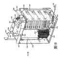
图20是具有用于装电缆接地接口的次级仓或舱的光纤分布集线器机箱的后视图;Figure 20 is a rear view of a fiber distribution hub chassis with a secondary compartment or compartment for housing cable ground interfaces;
图21是图20的光纤分布集线器的前视图,其中机箱开启并且旋架旋出了,以显示接地接口的接地引脚凸进了机箱的主仓的内部;FIG. 21 is a front view of the fiber distribution hub of FIG. 20 with the chassis open and the swivel frame swiveled out to show that the ground pins of the ground interface protrude into the interior of the main compartment of the chassis;
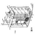
图22是图20的绝缘光纤分布集线器的机箱的次级仓的透视图;22 is a perspective view of a secondary compartment of the chassis of the insulated fiber distribution hub of FIG. 20;
图23是沿着图20的剖面线23-23的剖面图;Figure 23 is a cross-sectional view along section line 23-23 of Figure 20;
图24示出了可以从电信机箱的背后接入的可替换的次级仓的一个侧面;Figure 24 shows a side view of an alternative secondary compartment accessible from the back of the telecommunications enclosure;
图25示出了图24的可替换的次级仓的背面;Figure 25 shows the back of the alternative secondary cartridge of Figure 24;
图26是图24的次级仓的顶视图;Figure 26 is a top view of the secondary cartridge of Figure 24;
图27是沿着图26的27-27线的剖面图;Fig. 27 is a sectional view along line 27-27 of Fig. 26;
图28是图27的剖面图,其中接地电线延伸到次级仓之中并且耦合到次级仓之中的接地端头;FIG. 28 is a cross-sectional view of FIG. 27 with the ground wire extending into the secondary compartment and coupled to the ground terminal in the secondary compartment;
图29是图28的剖面图,除了其中一个接地电线已经脱离一个接地端头;Figure 29 is a cross-sectional view of Figure 28, except that one of the ground wires has been separated from a ground terminal;
图30是可替换的旋架的透视图;Figure 30 is a perspective view of an alternative swivel frame;
图31是旋架被旋出了的另一个光纤分布集线器(FDH)的透视图;Figure 31 is a perspective view of another fiber distribution hub (FDH) with the swivel frame swiveled out;
图32是图31的FDH的前视图,其中移除了顶板和旋架,使得能够观察FDH的内部;Figure 32 is a front view of the FDH of Figure 31 with the top plate and swing frame removed to enable viewing of the interior of the FDH;
图33是移除了旋架的图31的FDH的前视分解图;以及Figure 33 is a front exploded view of the FDH of Figure 31 with the swing mount removed; and
图34是图31的FDH的前视图,其中从旋架分解一个终端模块和旋架部分。FIG. 34 is a front view of the FDH of FIG. 31 with one end module and swivel portion exploded from the swivel.
具体实施方式Detailed ways
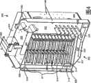
现在参考图2-7,示出了根据本发明公开的原理的示例性光纤分布集线器(FDH)200。FDH 200包括用于装容内部组件的机箱201。机箱201包括一个开口,其中馈电电缆(例如,或F1电缆)700和订户电缆708通过该开口来进出机箱201(见图2C)。旋架300可旋转地装配在机箱201之中的铰链355上。旋架300包括隔板301,其将旋架300分割为前部302(见图4)和后部304(见图2C)。隔板301包括具有终端区域311和存储区域313的主面板310。通常,终端区域311提供至少一个终端模块400(见图13A和13B)并且存储区域313提供至少一个存储模块600(见图9)。在一些实施例中,隔板301还包括紧邻主面板310并用于电缆管理的次级面板315。可以将一个或多个馈电电缆接口800放置在旋架300的后部之中。将至少一个用于容纳一个或多个分路器模块500的分路器模块机架322放置在旋架300的顶端。Referring now to FIGS. 2-7, there is shown an exemplary fiber distribution hub (FDH) 200 in accordance with the principles of the present disclosure.
图3是示出了FDH 200的示例性电缆布线方案的示意图。FDH 200通常在室外设备(OSP)环境中管理引入光纤和引出光纤之间的终端面板处的连接。作为本文所使用的术语,光纤之间的“连接”包括直接和间接的连接。引入光纤的实例包括进入机箱的馈电电缆光纤,以及用于将馈电电缆光纤连接到终端面板的中间光纤(例如,从分路器合配电光纤跳接器延伸出的连接引线)。引出光纤的实例包括离开机箱的订户电缆光纤,以及用于将订户电缆光纤连接到终端面板的任意中间光纤。FDH 200在网络中希望操作性接入和重新配置的地方提供光传输信号的互连接口。例如,如上文所示,FDH 200可以用于划分馈电电缆,并且将所划分的与布线到订户位置的分布电缆相连接的馈电电缆终止。另外,FDH 200用于容纳一系列可替换的大小和光纤支数,并且支持引线、扇出和分路器的工厂安装。FIG. 3 is a schematic diagram illustrating an exemplary cabling scheme for the
如图3所示,馈电电缆700最初通过机箱201(例如,典型地通过如图2C中所示的机箱201的背部或底部)布线到FDH 200。在某些实施例中,馈电电缆700的光纤可以包括带状光纤。一个示例性馈电电缆700可以包括12个到48个连接到服务提供商中心局101的独立的光纤。在一些实施例中,在进入机箱201之后,将馈电电缆700的光纤布线到馈电电缆接口800(例如,光纤适配器模块、配线盒等)。在馈电电缆接口800处,将馈电电缆700的一个或多个光纤分别连接到分离的分路器输入光纤702。将该分路器输入光纤702从馈电电缆接口800布线到分路器模块机架322。在分路器模块机架322处,将分路器输入光纤702连接到分离的分路器模块500,其中每个输入光纤702被划分为多个引线704,每个引线具有连接端706。然后,在其它实施例中,可以连接馈电电缆700的光纤并将其直接布线到分路器模块500,从而避免或消除了对中间馈电电缆接口800的需要。As shown in FIG. 3 , the
当引线704不服务的时候,连接端706可以临时存储在存储模块600上,存储模块600装配在旋架300的存储区域313中。当服务需要引线704的时候,将引线704从划分模块500布线到在旋架300的终端区域311处提供的终端模块400。在终端模块400处,将引线704连接到分布电缆708的光纤。终端面板是引入光纤和引出光纤之间的分割线。典型的分布电缆708形成了网络的F2部分(见图1),并且典型地包括了从FDH 200布线到订户位置709的多个光纤(例如,144、216或432个光纤)。When the leads 704 are not in service, the connection ends 706 may be temporarily stored on the
在一些实施例中,馈电电缆700的一个或多个光纤不与任意分路器模块500连接。然而,馈电电缆700的这些光纤连接到具有连接端714的穿透光纤712。该穿透光纤712连接到终端模块400,而无须首先连接到分路器模块500。通过制止划分光纤712,可以向其一个订户发送更强的信号。穿透光纤712的连接端714在不使用的时候可以存储在存储区域313处。In some embodiments, one or more optical fibers of
参考图2A-2C,FDH 200的机箱201包括顶板202、底板203、右面板204、左面板206、背板205或至少一个前门。在一些实施例中,该至少一个前门包括右门210和左门212。在一些实施例中,前门210、212包括锁211。使用铰链214、216将该至少一个前门可旋转地装配到机箱201上,以便于接入到装配在机箱201之中的组件。2A-2C, the
通常,FDH 200的机箱201用于保护内部的组件以免受雨水、风、尘灰、啃咬和其它污染物。然而,机箱201保持相对轻以便于安装,并且具有透气性以防止在该单元中湿气聚集。在一些实施例中,还提供了具有厚重粉末涂料的铝构造来防腐蚀。在一个示例性实施例中,用厚铝合金来制造机箱201,并且符合NEMA-4X标准。然而,在其它实施例中,还可以使用其它材料。Typically, the
根据示例性实施例,在电极装配或基座装配配置中提供FDH 200。例如,如图2中所示,可以在机箱201上提供环218,以便将机箱201部署在希望的位置。可以用起重机使用环218来放置机箱201。特别地,起重机能够将机箱201降低到地下区域。在一些实施例中,环218是可移除的或可调整的,以使其不凸出上机箱面板202。According to an exemplary embodiment, the
参考图2B-2C,FDH 200的旋架300包括顶板320、底板330、右面板340和左面板341。铰装条350位于旋架300的左侧341。如图4中所示,隔板301进一步包括用于将主面板310连接到铰装条350的连接板319。如图4所示的,次级面板315的部分325从旋架300的顶板320向上延伸。隔板301在顶和底板320、330之间垂直地延伸,并且在右面板340和左面板341之间横向地延伸。2B-2C, the
在一些实施例中,使用一个或多个铰链355将旋架300的铰装条350装配到FDH 200的机箱201。铰链355能够使整个旋架300从机箱201的前门210、212旋转出来,以能够接入旋架300的后部304中的光组件,以便清洁、测试、维护、增加等等,其中整个旋架300包括终端模块400、存储模块600、馈电电缆接口设备800和分路器模块500。从机箱201中旋转出旋架300导致旋架300的右面板340离开机箱201的内部容量空间。在一些示例性实施例中,可以将旋架300从机箱201中旋转出90度或更多。In some embodiments, one or
在一些实施例中,旋架300的铰链355用于向布线到旋架300的光纤电缆提供单个拐点。铰链点用于控制光纤的弯曲。特别地,本文所更详细说明的铰链355和电缆管理设备用于确定当旋架300开启或关闭的时候维持制造商所推荐的弯曲半径。在一个实施例中,可以在工厂或车间配置机箱201,使得电缆束缠绕在铰链355周围。预先配置机箱201降低了错误操作电缆的机会。In some embodiments, hinge 355 of
当旋架300处于开启位置的时候,如图2C中所示,旋架300的后部304中的组件是可接入的。例如,主面板310的后面和次级面板315的后面是可接入的。另外,当旋架300从机箱201旋转出来的时候,可以通过旋架300顶部开口来接入位于分路器模块机架322中的分路器模块500(见图4)。反之,当旋架300处于关闭的位置的时候(见图2B),仅旋架300的前部302上的组件是可接入的。When the
在示例性实施例中,旋架300包括插销(未显示),用于将处于关闭位置的旋架300锁在FDH 200的机箱201之中,直到将插销开动为止。一旦开动了插销,旋架300可以旋转出机箱201。另外,可以将旋转的锁闭组件(未显示)装配到旋架300的后侧面304,以便将旋架300保持在开启的位置。In an exemplary embodiment, the
参考图4-5,旋架300的存储区域313位于终端区域311的下方。然而,在其它实施例中,存储器313可以在终端区域311的上方或附近。通常,终端区域311定义至少一个矩形开口312,来自终端模块400的适配器450Referring to FIGS. 4-5 , the
(见图13A-13B)通过该矩形开口312进行延伸。本文更详细地描述了终端模块400。在图4中显示的实施例中,终端区域311包括开口312的两个端头,每个端头包括12个细长的槽。条形309分割开每个端头的开口312并且提供用于粘贴凸出物信息(例如,连接器名称)的表面区域。存储区域313还定义一个或多个开口314,其中存储模块600(见图9)装配在该开口314中。本文更详细地描述了存储模块600。(see FIGS. 13A-13B ) extends through the
隔板301将底板330分为前部331(见图4)和后部336(见图2C和14)。通常,底板330的前部331向前凸出隔板301。在一些实施例中,前部331进一步分割为第一前部332和第二前部334。前部332、334中的每一个分别包括凸缘333、335,其实质上垂直地凸出底板330的。因此,底板330的前部331形成了槽,用于支持来自存储区域313或来自次级面板315的松散或过剩的光纤。第一前部332的边缘337是有角度的,以允许旋架300旋转开启,同时不干扰该槽。The
如图4和6中所示的,隔板将面板340分别分割为前和后凸缘342、344。前凸缘342从次级面板315向前延伸,并且后凸缘344从次级面板315向后延伸。后凸缘344从底板330延伸到从顶板320延伸出来的弯曲限制器962。前凸缘342从底板330,通过顶板320,延伸到次级面板315的凸出部分325。在一些实施例中,前凸缘342包括与后凸缘344实质上平行的前向部分344,以及在次级面板315的凸出部分325和前向部分344之间延伸的弯曲部分343。As shown in Figures 4 and 6, the bulkhead divides the
如图7中所示的,旋架300的顶板320是实质上成直角的。顶板320包括前和后边缘326、327。凸缘323、324(见图4)分别从边缘326、327向上凸出。顶板320还有邻近侧面341的第一端328和邻近面板340的第二、正对端329。弯曲半径限制器940从第一端328向上延伸。在一些实施例中,顶板320的端329的部分通过面板340的前凸缘342定义了通道B的宽度。定义了通道B的端329的部分在到达端329的余下部分之前终止。通道B的深度从次级面板315延伸到底板330的第二前部33的凸缘335。As shown in FIG. 7, the
FDH 200的分路器模块机架322位于邻近第一端328的顶板320上。分路器模块机架322用于保护、组织并且紧扣FDH 200的分路器模块500。分路器模块机架322可以被构造成各种大小以容纳不同数量的分路器模块500。分路器模块机架322通常是矩形的并且在开口之中定义了一个或多个位置,其大小可以容纳一个或多个光分路器模块500。为了容纳分路器模块500,模块机架322包括用于支撑/紧扣分路器模块500的结构。在示例性实施例中,分路器模块500扣在分路器模块机架322中。在一个实施例中,将分路器模块500从前到后(例如,从面向端329的面到面向终端328的面)装入到分路器模块机架322中。将模块机架322进一步使得分路器模块500能够在分路器模块500的一个端上接收输入光纤(例如图3的光纤702),并且从分路器500的正对端输出多个光纤(例如图3的引线704)。The
现在参考图8A-8C,一种可以装配在分路器模块机架322中的分路器模块500是具有整合连接器的分路器。图8A是这种分路器模块500的左视图。分路器模块500包括机架505,其具有至少一个向前凸出的保护罩510以及至少一个向后凸出的整合连接器520。在显示的实施例中,两个罩510从前面凸出,并且两个整合连接器520从分路器机架505向后凸出。在一个示例性实施例中(未显示),每个分路器具有四个整合连接器520。在一些实施例中,把手540还从分路器机架505的前端凸出。图8B是图8A的分路器模块500的分解图,示出了分路器模块500的内部组件。Referring now to FIGS. 8A-8C , one type of
图8C示出了图7A的插入在分路器模块机架322中的分路器模块500的剖面图。使用扣件536将适配器配件530紧扣到分路器模块机架322。在一个实施例中,适配器配件530装配在分路器模块机架322的背后。将适配器配件530用于当分路器模块500插入到分路器模块机架322中的时候,接收分路器模块500的连接器520。如所示,适配器配件530进一步用于接收与馈电电缆700相关联的反向连接器。在一些实施例中,适配器配件530接收用于终止分路器输入光纤702的连接器703。在其它实施例中,适配器配件530接收用于终止馈电电缆700本身的连接器701。这样,馈电电缆光纤700可以耦合到分路器模块500。FIG. 8C shows a cross-sectional view of the
分路器模块500的其它实施例不包括整合连接器520。在这种实施例中,适配器配件530不装配在分路器模块机架322上,并且馈电电缆700不能直接插接到分路器模块500中。而是,输入引线(未显示)穿过分路器机架505并且进入分路器模块500。可以连接或非连接输入引线的正对端。如果端701在连接器中终止(未显示),那么输入光纤702使用适配器模块810(见图18)与馈电电缆接合。如果没有连接端701,那么输入光纤702使用配线盒808(见图19)与馈电电缆700接合。Other embodiments of
典型地,每个分路器模块500针对每个输入光纤接收一到四个光纤,并且输出两到十六个光纤704。在一个示例性实施例中,四个输入光纤702进入分路器模块500,并且三十二个引线光纤704离开分路器模块500。可以在2006年2月13日提交的、标题为“Fiber Optic Splitter Module”的美国临时专利申请号11/354,297中找到关于分路器模块500的进一步信息。可以在2004年11月3日提交的、题为“Fiber Optic Module And SystemIncluding Rear Connectors”的美国专利申请号10/980,978中;2005年5月25日提交的、题为“Fiber Optic Splitter Module”的美国专利申请号11/138063中;2005年8月29日提交的、题为“Fiber Optic Splitter ModuleWith Connector Access”的美国专利申请号11/215837中以及2005年12月28日提交的、题为“Splitter Modules For Fiber Distribution Hubs”的美国专利申请号11/321696的公开中找到关于分路器模块的其它类型的额外信息,将以上公开一并引入本文作为参考。Typically, each
现在参考图9-10,可以将分路器模块500和存储模块600不断添加到旋架300。图9示出了具有从分路器模块500上的保护罩510离开的多个连接引线704的分路器模块500。典型地,在安装到旋架300上之前,将连接引线704存储在一个或多个存储模块600中。在一些实施例中,在分路器模块500出厂前,每个引线704的连接器706紧扣在存储模块600中。典型地,将每个分路器模块500的连接引线704布线到四个存储模块600,其中每个存储模块600支持八个连接器。Referring now to FIGS. 9-10 ,
存储模块600包括具有前侧面602和后侧面604的主体610。主体610用于支持至少一个光纤连接器706。典型地,主体610支持大约八个连接器706。在一些实施例中,主体610用于将光纤连接器706保持单排配置。在其它实施例中,主体610可用于将连接器706保持为平行形式或其它希望的配置。可以在2003年6月30日提交的、题为“Fiber Optic Connector Hoderand Method”的美国专利申请号10/610,325中;2003年7月2日提交的、题为“Telecommunications Connection Cabinet”的美国专利申请号10/613,764中以及2004年6月18日提交的、题为“Multi-position Fiber OpticConnector Hoder and Method”的美国专利申请号10/871,555的公开中找到关于存储模块600的更多的信息,将以上公开一并引入本文作为参考。The
在一些实施例中,主体610扣入主面板310的存储区域313中所定义开口314中的一个。开口314可以是主面板310的存储区域313之中的任意希望的配置。在图10中显示的示例性中,主面板310的存储区域313定义了九个矩形的开口314。每个开口314用于接收存储模块主体610,存储模块主体610用于将八个光纤连接器保持为一行。In some embodiments, the
如图10所示,当在安装期间将分路器模块500装入到分路器模块机架322的时候,将相应的存储模块600装入主面板310的存储区域313中。为了便于观察,仅仅示出了具有一个引线704的一个分路器500和一个存储模块600。将从分路器模块500延伸到存储模块600的引线704从保护罩510,穿过顶板320,向下通过次级面板315的前侧面上的通道B,并且穿过旋架300的底板330进行布线。As shown in FIG. 10 , when the
为了完成该布线,顶板320和次级面板315包括电缆管理配置。在一些实施例中,顶板320上的电缆管理配置包括位于分路器机架322和弯曲半径限制器962之间的第一线轴952,以及位于弯曲限制器940和前凸缘342之间的第二线轴954。从分路器500输出的引线704首先被缠绕在第一线轴952的周围然后在第二线轴954的周围。To accomplish this routing, the
弯曲半径限制器964具有凸出物965并且从顶板320向下延伸,其部分地定义了通道B。一些引线704在弯曲限制器964上从第二线轴954布线到通道B。在一些实施例中,装配了局部光纤线轴966,以使其从次级面板315的凸出部分延伸,并且将光纤布线到通道B中。为了避免光纤704超重或乱绕,一些光纤704可以在局部线轴966而不是弯曲限制器964上布线到通道B中。还可以通过在线轴966上而不是弯曲限制器964上布线引线704来避免过于松散。弯曲限制器968还可以装配在次级面板315的凸出部分325上,并且用于将光纤布线到局部线轴966上。
次级面板315的前面包括至少一行局部线轴970和至少一行半径限制器980。在一个示例性实施例中,局部线轴970用于使得向下布线到通道B的光纤能够至少部分地缠绕其中一个线轴970。光纤可以从局部线轴970沿着底板330行进到存储模块600,或者在限制器980上行进到终端模块400。限制器980用于使得从局部线轴970布线的光纤能够行进到终端模块400而不会过于弯曲。The front of the
现在参考图11,当保留在存储模块600中的引线704将被连接到订户分布线路708的时候,从存储模块600移除相应的连接器706并且将其转移到终端模块400上的合适的适配器450。在此转移过程中,可能需要将光纤重新绕到不同的局部线轴970(例如局部线轴972),以便到达适配器450。在到达适配器450之前,可以将光纤从局部线轴972布线到合适的限制器980周围,以避免过于弯曲。在一些实施例中,在插入适配器450之前,还将光纤贯通支撑指990,该支撑指990从主面板310的终端截面311延伸。当将最初紧扣在存储模块600中的所有的光纤704布线到订户终端模块400的时候,可以移除空的存储模块600,一并给新的分路器模块500和新的存储模块600腾出空间。Referring now to FIG. 11 , when the
现在参考图12A-12B,随着时间推移以及订户数量的增加,用户可以将终端模块400添加到旋架300。图12A和12B示出了终端模块400的一个实例。终端模块400包括实质上为L形配置的终端支架410和管理支架420。在一些实施例中,链接截面430将终端支架410连接到管理支架420。在其它实施例中,链接截面430独立与终端支架410或管理支架420集成在一起。在其它实施例中,终端支架410、管理支架420和链接截面430集成为单片电路(例如,作为单片弯曲的金属片)。Referring now to FIGS. 12A-12B , a user may add
在一些实施例中,终端模块400的终端支架410的前侧面(图12B中所示的)装配在主面板310的后面。在一个实施例中,终端支架410使用螺丝钉417装配到主面板310。然而,在其它实施例中,可以使用例如螺栓、铆钉、钉子之类的扣件或其它这种设备来将模块400连接到主面板310。在其它实施例中,可以使用粘合剂将模块400粘到主面板310上。In some embodiments, the front side of the
每个终端模块400包括至少一行光纤适配器450,用于将主电缆700的光纤连接到分布电缆708的光纤。每个适配器450具有前端452和后端454。每个适配器450的前端452用于保持与主线路700相连接的光纤712的连接器714,或保持与主线路700分离的光纤704的连接器706。每个适配器450的后端454用于保持分布电缆708的光纤的连接器710。适配器450从终端支架410凸出,使得连接器706从主面板310的前侧面进入适配器450的前端452,并且分布电缆708的连接器710从主面板310的后侧面进入适配器450。Each
在所述的实施例中,每个模块400包括六行水平的适配器450,其共同定义了两个并行的适配器组。当模块400装配到主面板310的时候,支架410的前侧面紧邻主面板310的后侧面,并且适配器450行从面板310所定义的相应的水平槽314向前凸出。In the depicted embodiment, each
管理支架420从终端支架向后延伸。每个管理支架420包括恰当数量的扇出424以适应模块400上的适配器450的数量。例如,在一个实施例中,模块400的终端支架410包括六行适配器450,每行具有十二个适配器450,并且管理支架420包括六个12:1扇出424。如本文所使用的术语,12:1扇出是用于接收十二个光纤并且输出包含十二个光纤的单电缆带的扇出。在另一个实施例中,可以提供九个8:1扇出或三个12:1扇出,而不是12:1扇出。在其它实施例中,可以使用扇出来给光纤加套。The
在一些实施例中,在工厂对终端模块400预先装配电缆,以包括耦合到每个适配器450的连接分布光纤708。通常在适配器450的前端452上提供防尘罩453以保护终端分布光纤708免受尘灰、污垢和其它污染物的污染。将每个分布光纤708的连接器710装配在适配器450的后端454之中,并且将分布光纤708从连接器710布线到在终端模块400的管理支架420上提供的扇出424。在其它实施例中,不对终端模块400预先装配电缆,并且仍然在适配器450的后端454上提供防尘罩455以保护适配器450。In some embodiments, the
在一些实施例中,终端模块400的管理支架420还包括至少一个电缆管理设备425,用于管理分布光纤708的过多的光纤长度。通常,在这种系统中,首先将光纤708布线到电缆管理设备425,然后布线到扇出424。电缆管理设备425的实例包括光纤线轴、一个或多个半径弯曲限制器、一个或多个光纤夹子和其它这种设备。在所示的实例中,管理支架420包括由两个半径弯曲限制器形成的光纤线轴426。每个半径弯曲限制器包括用于保持线轴426上的光纤的凸缘427。在一些实施例中,可以在线轴426的半径弯曲限制器之间隔开用于保持光纤电缆的一个或多个光纤电缆夹子428。In some embodiments, the
现在参考图13,终端模块400的管理支架420包括开口422,其中通过该开口将光纤从电缆管理设备425布线到扇出424。一旦离开扇出424,将带状光纤布线到机箱扇出(未显示)或其它电缆接口设备。在其它实施例中,在与电缆管理设备425的管理支架420的同侧提供扇出424。在这种实施例中,将带状光纤从扇出424穿过开口422布线到机箱扇出。该机箱扇出装配到机箱201的内部并且未附着在旋架300上。机箱扇可用于将带状光纤减少为离开FDH 200的单个加套的短电缆。短电缆与FDH 200外部的订户分布电缆接合。在各种实施例中,短电缆的长度范围从大约25英尺到大约300英尺。在其它实施例中,可以将分布电缆708布线到机箱201中并且接合或连接到光纤708。Referring now to FIG. 13 ,
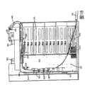
现在参考图14,旋架300的后侧面304形成了一个开口仓,用于装至少一个终端模块400。通过隔板301、顶板320、底板330和侧面板340定义该开口仓。图14是装配在开口仓中的四个终端模块400的后视图。为了便于观察,移除了适配器450。在其它实施例中,可以将任意希望数量的终端模块400装配到旋架300上。将终端模块400装配到主面板310的终端区域311的后侧面。Referring now to FIG. 14 , the
图15示出了具有装配在其中的四个终端模块400的旋架300的左视图。当将多个终端模块400装配到主面板310的后侧面的时候,终端模块400的管理支架420形成了正对侧面板340的部分侧面板。在一些实施例中,将模块400的管理支架420互相紧扣或紧扣到旋架300。在其它实施例中,图15中所示,仅仅在终端支架410处将模块400紧扣到旋架300,并且管理支架420不移动。FIG. 15 shows a left side view of the
现在参考图16-19,可以将不同的接口设备800(见图3)和电缆管理设备配置到旋架300,以便在进入馈电电缆700和分布线708之间创建多个光纤路径。以特殊的配置来使用的接口设备800和管理设备取决于是否希望划分馈电电缆700和使用什么类型的分路器模块500。Referring now to FIGS. 16-19 , various interface devices 800 (see FIG. 3 ) and cable management devices can be deployed to the
在一些实施例中,馈电电缆700连接到一个或多个分路器输入光纤702。在一个这种实施例中,分路器输入光纤702的第一端701是连接的。在另一个这种实施例中,第一端701是非连接的。输入光纤702的正对端703可以与分路器模块500上的整合连接器520接口,例如当使用图8A-8C中所述的分路器模块时,或可以穿透分路器机架505。然而,在其它实施例中,馈电电缆700具有用于与分路器模块500的整合连接器520相连接的连接器。In some embodiments, the
图16是用于将连接馈电电缆700与分路器模块500相连接的旋架300的后视图。为了完成该接口,根据配置C1来排列电缆管理设备。在配置C1中,将电缆存储线轴922和一个或多个部分存储线轴924装配到旋架300的侧面板340上。将扇出设备926装配到相邻的线轴922、924。半径限制器936装配在顶板320和侧面板340所形成的角落附近的次级面板。从顶板320向下凸出的支撑指932形成了路径A,其中可以沿着该路径A将光纤从顶板320一端329布线到另一端328。在一些实施例中,支撑指932包括具有至少两个指932的多叉夹子934,每个指932向不同的方向延伸。在一个示例性实施例中,多叉夹子934包括四个彼此正交的指932。可以通过将引线702缠绕在多叉夹子934上来避免光纤过长。具有凸出物945的限制器945从顶板延伸。FIG. 16 is a rear view of the
为了将馈电电缆700连接到分路器500,首先将电缆700绕着线轴922、924布线,然后布线到扇出设备926。扇出设备926将馈电电缆700的光纤分离为独立的输入光纤。可以通过将光纤缠绕到线轴922、924上来减小馈电电缆700的独立地光纤的长度。接着,使用从顶板320向下凸出的支撑指932,在限制器936周围,并且沿着路径A对馈电电缆700的光纤进行布线。接着,在绕着从顶板320延伸的限制器940来弯曲馈电电缆700,并且直接将其插入到紧扣到分路器模块机架322上的至少一个适配器配件530。当在旋架300之中通过松散缓冲器管子来布线时,可以保护馈电电缆700的光纤。To connect the
图17是用于将连接的馈电电缆700与分路器模块500相连接的旋架300的后视图。根据配置C1的变体来排列电缆管理设备。将存储线轴922、924和扇出设备926装配到次级面板315而不是侧面板340的后侧面。在其它实施例(未显示)中,可以将存储线轴922、924和扇出设备926装配到底板330上。不管线轴922、924和扇出设备926的位置在哪里,仍然将馈电电缆700从扇出设备926沿着路径A在弯曲限制器940上布线到弯曲限制器936,并且布线到装配在分路器模块机架322上的适配器配件530。FIG. 17 is a rear view of the
现在参考图18-19,可以使用至少一个接口设备800将馈电电缆700与分路器输入702相连接,而不是将其直接连接到分路器500。图18是旋架300的后视图,其用于通过中间分路器输入光纤702来将连接馈电电路700与分路器模块500相连接。每个分路器输入光纤702具有第一连接端703,其插入到一个与分路器500的整合连接器520正对的适配器配件530中。然而在其它实施例中,不使用具有整合连接器的分路器,分路器输入702是穿透分路器机架505而不插入适配器配件530的引线。每个分路器输入光纤702还具有第二连接端701,其与馈电电缆700的光纤的连接端相连接。Referring now to FIGS. 18-19 , at least one
如图16中所示,在弯曲半径限制器940上和顶板320下,从适配器配件530布线这种输入引线702。特别地,使用支撑指932,沿着路径A朝着侧面板340布线输入引线702,然后将其绕着半径弯曲限制器936布线。然后使用第一适配器模块820,将输入引线的端701连接到馈电电缆700。在一些实施例中,将第一适配器模块装配到与底板330相邻的次级面板315。然而,在其它实施例中,可以把第一适配器模块820紧扣到底板330或侧面板340上。第一适配器模块820包括排列成一行或者多行的多个适配器825。在一些实施例中,每行包括大约六个适配器825。可以在2005年3月31日提交的、题为“Adapter Block Including Connector Storage”的美国专利申请号11/095,033中以及美国专利申请号5,497,444、5,717,810、5,758,003和6,591,051中找到关于适配器模块820的额外的信息,其中将该专利的公开一并引入作为参考。Such input leads 702 are routed from the adapter fitting 530 as shown in FIG. 16 over the
为了将馈电电缆700连接到第一适配器模块820,根据第二配置C2提供了额外的电缆管理设备。第二配置C2包括扇出设备901和一个或多个全松散存储光纤线轴902或者部分松散存储光纤线轴904。在显示的实例中,扇出设备901和存储线轴902、904装配到底板330上。In order to connect the
首先将馈电电缆700布线到扇出设备901,扇出设备901将带状电缆700的光纤分离为独立的光纤。可以将馈电电缆700的独立的光纤的任意过多长度存储在松散存储线轴902和部分松散存储线轴904中。然后将馈电电缆700的光纤布线到第一适配器模块820。将馈电电缆700的连接端装配到第一适配器模块820的适配器825的一端中。将输入光纤702的连接端701从半径限制器936布线到第一适配器模块820的适配器825的正对端。适配器825提供馈电电缆光纤700的连接器和输入光纤702的连接器701之间的接口。The
图19是用于与分路器模块和具有非连接端的馈电电缆700一起使用的旋架300的后视图。将馈电电缆700接合到具有非连接的第二端701的分路器输入光纤702。为了将馈电电缆700连接到非连接的光纤输入702,在旋架300的后侧面304提供了配线盒830。FIG. 19 is a rear view of a
为了将馈电电缆700连接到配线盒830,根据第三配置C3提供了额外的电缆管理设备。第三配置C3包括扇出设备907和装配在配线盒830周围的一个或多个半径弯曲限制器906。另外,将至少一个半径弯曲限制器908置于配线盒830附近。每个限制器906包括凸出物907,用于将光纤维持在限制器906周围的环中。限制器906用于防止光纤钩住配线盒830的角。在一些实施例中,将配线盒830和限制器906置于次级面板315的后面。然而,在其它实施例中,可以将配线盒830和限制器906可以置于旋架300的后侧面304的任意希望的位置。In order to connect the
将馈电电缆700的非连接的端布线在限制器906周围并且布线到配线盒808。可以通过将光纤缠绕在接合830周围来存储馈电电缆700的任意过长的独立的光纤。将来自分路器模块500的输入光纤702从半径限制器936布线到限制器908周围,并且布线到配线盒830中。然后,将馈电电缆700的非连接端与输入光纤702的非连接端接合。The unconnected end of the
参考图16-19,在一些实施例中,不希望划分一个或多个馈电电缆700,以使更强或更多的可靠信号能够发送到订户。因此,在一些实施例中,旋架300进一步用于使至少一个光纤(称为穿过光纤)712与来自馈电电缆700的光纤相连接。该穿过光纤712绕过分路器模块500并且前进到旋架300的前面以与分布线路708相连接。Referring to Figures 16-19, in some embodiments it is not desirable to divide one or
为了实现这种布线,旋架300包括面板340的后凸缘344中的开口910。在一些实施例中,该开口910包括半径限制器912(最好见图13),其从凸缘344的外表面向外延伸,以防止穿过开口910布线的光纤的过于弯曲。还可以在后凸缘344中向外按压凸出物915,以定义后凸缘344的外侧面上的通道。半径弯曲限制器962将面板340的后凸缘344链接到顶板320。基于用于建立旋架300的配置C1,C2,C3来提供额外的电缆管理设备。To enable this routing, the
参考图17,如果根据配置C1排列旋架300,那么使用第二适配器模块810将馈电电缆700的连接光纤连接到输入光纤702。适配器模块810包括多个光纤适配器815,用于从任一端接收连接光纤。旋架300还包括弯曲半径限制器906形式的额外的电缆管理和松散存储线轴902、904。Referring to FIG. 17 , if the
为了绕过分路器模块500,仍然绕着线轴902、904将馈电电缆700布线到扇出设备926。然而,从扇出设备926,将馈电电缆700绕着线轴922、924、绕着弯曲限制器926然后绕着线轴902、904往回布线。从线轴902、904,将光纤700的连接端紧扣到适配器模块810。适配器模块810使用穿透光纤710的连接端来连接光纤700,其中该穿透光纤710从开口910向外布线,从侧面板340经过限制器962直到顶板320上。如上文参考图10和11所描述的,穿透光纤712从顶板320布线到终端模块400。To bypass the
参考图18,还可以与第二配置C2一起使用穿透引线712。首先仍然将馈电电缆700布线到扇出设备901,然后到适配器模块820的一端,其中将任意松散存储在线轴902、904中。然而,将穿透引线712插入到适配器模块820,而不是将分路器引线702连接到适配器模块820的另一端。然后,穿透引线712遵守与前段中所讨论相同的布线方式。Referring to FIG. 18, a piercing
参考图19,还可以将穿过引线712接合到馈电电缆700的非连接的端。如果希望这种配置,那么将上文图17所讨论的第二适配器模块810提供给旋架300。仍然根据配置C3,将馈电电缆700绕着限制器906布线到配线盒830。可以通过将光纤缠绕在限制器906周围来存储馈电电缆700的独立的光纤的任意过多的长度。然而,将馈电电缆700的光纤接合到连接引线711而非分路器输入702。连接引线711从配线盒830绕着存储线轴902、904布线,然后插入到第二适配器模块810中。第二适配器模块810使用穿透连接光纤712的连接端来连接引线711,其中该穿透连接光纤712从开口910向外布线,从侧面板340到限制器962直到顶板320上。Referring to FIG. 19 , a feed-through
穿透光纤712绕过分路器模块500,并且经由限制器964或局部线轴966绕着顶板320的第二光纤线轴布线,并且进入通道B中。沿着旋架的前侧面302的穿透光纤712的布线实质上与上文图10和11所讨论的分路器引线704的布线相同。典型地,将穿透光纤712经由终端模块400上的适配器450,立即连接到订户线路708。然而,在一些实施例中,可以将穿透光纤712存储在存储模块600的空白位置上。The piercing
图20-29示出了具有根据本发明公开的原理的特征的可替换的光纤分布集线器(FDH)。图20-23中示出了一个示例性FDH 200’。光纤分布集线器200’包括用于装容与前文所述的光纤分布集线器200相同的组件的机箱201’。例如,机箱201’定义了可以通过开启前门210、212来接入的主仓。旋架300可旋转地装配在主仓230之中。在旋架上提供终端区域和存储区域。在旋架上还提供分路器。通过参考关于光纤分布集线器200的详细的描述,可以找到关于主仓230的内部组件的进一步的细节。20-29 illustrate an alternative fiber distribution hub (FDH) having features in accordance with the principles of the present disclosure. An exemplary FDH 200' is shown in FIGS. 20-23. The fiber distribution hub 200' includes a chassis 201' for housing the same components as the
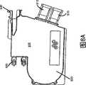
修改了光纤分布集线器200’,以使其包括可以从机箱201’的背后接入的次级仓232。还可以将次级仓232称为舱、凹处、插入区域、膛等等术语。可以通过开启次级门234来接入次级仓232。次级门234位于机箱200’的外面。当次级门234开启的时候,将接入提供给次级仓232,但是不将接入提供给机箱201’的主仓230。因此,现场技术员可以快速地找到并且进入次级仓232,而不用打扰光纤分布集线器200’的任意内部电信组件。The fiber distribution hub 200' is modified to include a
参考图22,次级仓232是由具有装配凸缘部分237和围栏部分239的面板所235定义的。装配凸缘部分237绕着围栏部分239的周界延伸。该围栏部分239从装配凸缘部分237向后凸出,并且定义了通常为矩形的凹处,该凹处形成了次级仓232。如所示,次级门234通过铰链240可旋转地连接到面板235。可以通过传统的插销配置将次级门234紧扣到关闭的位置。在一个实施例中,可以通过门闩(未显示)将次级门234保持在关闭的位置,其中该门闩延伸出开口242,并且穿入面板235的开口244所紧扣的紧扣螺母(未显示)。Referring to FIG. 22 , the
如图20所示的,面板235装配到机箱201’的后壁246上。机箱201’的后壁246具有用于接收面板235的围栏部分239的开口248。为了将面板235装配到后壁246,将围栏部分239插进开口248,并且将面板235的装配凸缘部分237紧扣到后壁246(例如,使用螺母或其它扣件)。可以在装配凸缘部分237和后壁246之间提供密封垫圈250(图3所示)以防止湿气进入机箱201’的主仓230。如图21所示,当将面板235装配到后壁246的时候,围栏部分239轻微地突进主仓里。As shown in Figure 20, the
次级仓232用于保护并且提供对于接地接口255的可用接入,其中接地接口255用于使机箱201’和进入/离开机箱201’的屏蔽电缆相互连接到地面。如图22所示,接地接口255包括诸如底座接地端头260和五个电缆接地端头262的终端。在优选实施例中,端头260、262全部沿着它们的长度方向在外表上带有螺纹。端头260、262全部穿过导电的总线面板266所定义的开口。在一个实施例中,总线面板是例如铜的金属。螺母264的面板接触组件(例如凸缘)的每个端头260、262上是带螺纹的。当将凸起的螺母264向下拧入总线面板266的时候,总线面板266作为电气总线,其将所有接地端头260、262彼此电连接。最好将底座接地端头269电连接到地面。因此,当总线面板266将所有端头62、262彼此电连接的时候,通常所有端头260、262都接地了。The
当现场技术员需要指导定位器信号穿过一个通过接地接口来接地的电缆的屏蔽层的时候,希望从地面断开电缆的屏蔽层,并且将选择的电缆与其它电缆绝缘。这最好便捷、不费时地完成。在所示出的实施例中,可以仅将与电缆相对于的凸起螺母264后退一定距离,来使得凸起的螺母364不再接触总线面板266,从而从地面断开给定的电缆。随着凸起的螺母的后退,从底座接地端头260断开选择的电缆接地端头262。这使得很容易通过选择的电缆接地端头262来指导定位器信号到达希望定位的电缆的屏蔽层。When a field technician needs to direct a locator signal through the shield of a cable that is grounded through a ground interface, it is desirable to disconnect the cable shield from ground and to insulate the selected cable from other cables. This is preferably done conveniently and without time consuming. In the illustrated embodiment, the raised
图23示出了总线面板266的示例性装配配置。如图23所示的,第一绝缘套管270将每个电缆接地端头262与总线面板266电绝缘,并且第二绝缘套管272将每个电缆接地端头262与面板235电绝缘。绝缘套管270、272通常最好是圆柱形管,其安装在电缆接地端头262上并且安装在分别由总线面板266和面板235定义的开口之中。第一和第二端头保持螺母274、276拧到电缆接地端头262上,以将端头262锁紧到恰当的位置,并且防止端头262的轴移动。例如,端头保持螺母274、276在端头262上互相穿入,直到将面板235夹紧在螺母274、276之间为止。将绝缘垫圈277、278装配在端头保持螺母274、276和面板235之间,以使得螺母274、276与面板235电绝缘。可以在电缆接地端头262上提供额外的螺母280,用于将电线连接到端头。例如,可以将电线一端夹在螺母280、276之间,同时另一端电连接(例如,通过夹子)到布线到光纤分布集线器200’的电缆的金属屏蔽层。FIG. 23 shows an exemplary assembled configuration of
典型地,因为不希望将总线面板266或面板235与底座接地端头260绝缘,所以底座接地端头260的配置装配稍微不同。在示出的实施例中,使用螺母286、288来将底座接地端头260紧夹到面板235上。在面板235和底座接地端头260之间不提供套管或其它绝缘体。从而,最好一直将底座接地端头260电连接到面板235。可以使用额外的螺母289将接地电线紧扣到底座接地端头260。接地电线290最好从底座接地端头260行进到地面。还在底座接地端头260上提供螺母292,以提高总线面板266和底座接地端头260之间的电连接。Typically, the
在可替换地实施例中,还可以在底座接地端头260和总线面板266之间提供绝缘套管。这样,通过后退凸起的螺母292,所有五个电缆接地端头262将与地面断开。这样,技术员可以通过指示信号穿过一个电缆接地端头262来同时指示定位信号穿过所有电缆屏蔽层。In an alternative embodiment, an insulating sleeve may also be provided between the
如上文所述,底座接地端头262用于将机箱201’接地。因此,面板235和机箱201’的主体之间最好存在电连接。这可以通过面板235的装配凸缘部分237和机箱201’的后壁246之间的金属到金属接触区域来提供。可替换地,还可以使用电线294来提供主后壁246和面板235之间的电连接。可以使用类似的电线提供前门210、212和机箱201’的主体之间的电连接。As mentioned above, the
再参考图21和23,端头260、262的内部端位于机箱201’的主仓230之中。如图23所示的,通过电线251将底座接地端头260的内部端电连接到地面297(例如,插入地面中的金属端头),其中该电线251从端头260的内部端延伸,穿过机箱的底部到达地面。类似地,将两个所述电缆接地端头262的内部端电连接到电缆298、299的屏蔽层,其中电缆298、299布线到光纤分布集线器200’。可以使用传统电线252、253来提供端头262的内部端和电缆298、299之间的电连接。一旦连接了电线251-253,现场技术员不需要打扰或断开电线251-253。改为可以电缆298、299独立地与次级仓232之中地主机箱230绝缘,而不在主仓230之中工作。Referring again to Figures 21 and 23, the inner ends of the
在通常应用中,到达光纤分布集线器200’的现场技术员仅仅需要开启次级门234以接入接地接口255。随着次级门234开启,技术员识别与希望定位的地下电缆相对应的电缆接地端头262。然后,现场技术员松开对应于选择的电缆接地端头262的凸起的螺母264,使得端头262与总线面板266绝缘并且从地面断开。随着使端头262绝缘,可以将定位器信号通过电缆接地端头262发送到希望定位的地下电缆的屏蔽层。在定位并且标记了电缆之后,将凸起的螺母264向下紧扭向总线面板266,使得电缆重新电连接到地面。In a typical application, a field technician reaching the fiber distribution hub 200' need only open the
图24-29示出了可以从机箱201’的背后接入的可替换的次级仓232’。可以通过开启位于机箱200’的外面的次级门234’(图27)来接入次级仓232’。次级门234’实质上类似于以上图20-23所述的次级门234。当次级门234’开启的时候(见图28),可以接入次级仓232’,但是不可以接入机箱201’的主仓230(图21)。因此,现场技术员可以快速地找到并且进入次级仓232’,而不打扰光纤分布集线器200’的任意内部电信组件。24-29 illustrate an alternative secondary compartment 232' that can be accessed from the rear of the chassis 201'. The secondary compartment 232' can be accessed by opening a secondary door 234' (FIG. 27) located on the exterior of the chassis 200'. The secondary gate 234' is substantially similar to the
通常,次级仓232’是由具有装配凸缘部分237’和围栏部分239’(图25)的面板235’(图24)定义的。装配凸缘部分237’在围栏部分239’的周围延伸。该围栏部分239’从装配凸缘部分237’突向机箱200’的主仓230。该围栏部分239’定义了通常为矩形的凹处,该凹处形成了次级仓232’。面板235’通常装配到机箱201’的面板,例如,到后壁246(图20),以与前文关于面板235所述的实质上相同的方式,例如,扣件238’。Generally, the secondary compartment 232' is defined by a panel 235' (Fig. 24) having a mounting flange portion 237' and a fence portion 239' (Fig. 25). Mounting flange portion 237' extends around fence portion 239'. The fence portion 239' protrudes from the mounting flange portion 237' towards the
次级仓232’用于保护现成的接入并且将其提供给接地接口255’,其中接地接口255’用于使机箱201’和进入/离开机箱201’的屏蔽电缆相互连接到地面。通常,通过将来自电缆298、299(图21)的传统电子接地电线252’、253’馈入次级仓232’中并且将电子接地电线252’、253’的各个端上的电子接触器258’耦合到接地接口255’来将屏蔽电缆接地。The secondary compartment 232' is used to protect the existing access and provide it to the ground interface 255', which is used to interconnect the chassis 201' and the shielded cables entering/exiting the chassis 201' to ground. Typically, this is accomplished by feeding conventional electrical ground wires 252', 253' from
通过面板235’的围栏部分239’和机箱201”的后壁246之间所定义的开口,将电子接地电线252’、253’馈入到次级仓232’中。典型地,支持结构268沿着这些开口延伸,以便围住次级仓232’从而保护主仓230’的内部组件和次级仓232’的内部组件。支持结构268还将电子电线252’、253’导入次级仓232’中。例如,可以在次级仓232’的一面或两面上提供具有一个或多个孔269的泡沫插入物268,其中电子电线252’、253’的布线可以穿过该孔。The electrical ground wires 252', 253' are fed into the secondary compartment 232' through the opening defined between the fenced portion 239' of the panel 235' and the
如图24所示的,接地接口255’包括例如接地端头262’的终端。在优选实施例中,接地端头262’都在外表上带有沿着它们的长度方向的螺纹。端头262’从一个或多个导电的总线面板266’凸起(见图27)。在一个实施例中,由诸如铜的金属来形成总线面板266’,并且将端头262’焊接到总线面板266’。总线面板266’作为将接地端头262’彼此电连接的电子总线。最好将总线面板266’电连接到地面,因此,将所有接地端头262’电连接到公共地面。As shown in Figure 24, the ground interface 255' includes a termination such as a ground terminal 262'. In a preferred embodiment, the ground terminals 262' are externally threaded along their length. Terminals 262' project from one or more conductive bus panels 266' (see Figure 27). In one embodiment, the bus panel 266' is formed from a metal, such as copper, and the terminals 262' are soldered to the bus panel 266'. The bus panel 266' acts as an electrical bus that electrically connects the ground terminals 262' to each other. Preferably, the bus panel 266' is electrically connected to ground, and therefore, all ground terminals 262' are electrically connected to a common ground.
可以以各种方式将总线面板266’电连接到地面。例如,其中一个接地端头262’可以作为如上文关于接地接口255所述的底座接地端头。在其它实施例中,使用例如门闩236’将总线面板266’装配到面板235’,以将总线面板266’和面板235’电连接。将面板235’装配到机箱201’,机箱201’可以电连接到地面。The bus panel 266' can be electrically connected to ground in various ways. For example, one of the ground terminals 262' may serve as a base ground terminal as described above with respect to the
图26-27示出了总线面板266’的一个示例性装配配置。如所示,每个电缆接地端头262’具有紧扣(例如,焊接、压入或固定)在总线面板266’所定义的开口之中的基端。在每个电缆接地端头262’上提供第一和第二螺母280’、282’,用于将电线252’、253’连接到接地端头262’(图28)。26-27 illustrate an exemplary assembled configuration of the bus panel 266'. As shown, each cable ground lug 262' has a base end that is snapped (e.g., welded, pressed, or secured) into an opening defined by the bus panel 266'. First and second nuts 280', 282' are provided on each cable ground terminal 262' for connecting the wires 252', 253' to the ground terminal 262' (Fig. 28).
例如,如图28中所示地,可以将电线252’的一端上的电子接触器258’夹在第一和第二螺母280’、282’之间。在一些实施例中,可以在电子接触器和第一螺母280’之间以及电子接触器和第二螺母282’之间装配绝缘垫圈(未显示),以将电子接触器与螺母280’、282’绝缘。For example, as shown in FIG. 28, the electrical contact 258' on one end of the wire 252' may be sandwiched between the first and second nuts 280', 282'. In some embodiments, insulating washers (not shown) may be fitted between the electrical contactor and the first nut 280' and between the electrical contactor and the second nut 282' to connect the electrical contactor to the
当希望从地面断开电缆的屏蔽层并且将其它电缆与选择的电缆绝缘的时候,从接地端头262’移除电线252’上的电子接触器258’。通过首先从端头262’移除第一螺母280’,然后将电子接触器258’从端头262’拖出来,从而移除电子接触器258’。随着移除电子接触器,将选择的电线252’从地面断开,同时接地端头262’保持接地。这允许轻易地指导定位器信号穿过电子电线252’以到达希望定位的电缆的屏蔽层。Electrical contactor 258' on wire 252' is removed from ground terminal 262' when it is desired to disconnect the shielding of a cable from ground and to insulate other cables from the selected cable. The electrical contactor 258' is removed by first removing the first nut 280' from the end 262' and then pulling the electrical contactor 258' away from the end 262'. With the electrical contactor removed, the selected wire 252' is disconnected from ground while the ground terminal 262' remains grounded. This allows the locator signal to be easily directed through the electronic wire 252' to the shield of the cable where it is desired to locate.
要认识到,光纤分布集线器200可以制造成各种不同的尺寸。然而,为了提高制造效率,最好用具有统一长度的引线来制造分路器。为了容纳不同尺寸的光纤分布集线器,最好将引线设计到足够长以便在期望使用的最大光纤分布集线器中工作。对于更小的分布集线器,可以通过将过多的长度缠绕在光纤存储区域来收缩在引线中过多的长度。例如,可以将过多的长度缠绕在旋架的上部提供的线轴252、254(见图7)上。It will be appreciated that
图30示出了旋架300’,其利用可替换地技术来使用不同尺寸的光纤分布集线器的统一长度的引线。图30的旋架300’具有装配在旋架的左前顶端的分路器模块机架322’。为了解决不同尺寸旋架的不同规格,可以将分路器模块装配在旋架的顶端的不同位置。例如,如果标准尺寸的引线太短以致不能到达给定旋架上的终端面板,其中分路器装配在该旋架的顶端的远处左角,那么可以将分路器装配移动到中间装配位置257,或右装配位置259,以将额外的长度提供给引线。Figure 30 shows a swivel frame 300' utilizing an alternative technique to use uniform length pigtails of different sized fiber distribution hubs. The swing frame 300' of FIG. 30 has a splitter module rack 322' mounted on the left front top of the swing frame. In order to solve the different specifications of the swivel frame with different sizes, the splitter module can be assembled at different positions on the top of the swivel frame. For example, if the standard size leads are too short to reach the termination panel on a given swivel where the splitter is mounted on the top far left corner of the swivel, then the splitter assembly can be moved to the middle assembly position 257, or right assembly position 259, to provide extra length to the leads.
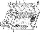
现在参考图31-34,示出了具有根据本发明公开的原理的特征的另一个光纤分布集线器(FDH)200”。光纤分布集线器(FDH)200”包括另一个示例性机箱201”。已经修改了机箱201”,以便包括装配到机箱201”的背面板205和/或侧面板204、206上的电缆管理面板220(见图31和32)。电缆管理面板220可以包括在面板220中打出的线圈222。线圈222允许电缆从其中穿过,以将将一个或多个电缆紧扣到相对于机箱201”的面板204-206固定的位置。Referring now to FIGS. 31-34 , there is shown another fiber distribution hub (FDH) 200 ″ having features in accordance with the principles disclosed herein. The fiber distribution hub (FDH) 200 ″ includes another
现在参考图33,光纤分布集线器200”可以装配到接入仓1000。该接入仓1000包括顶板1002、底板1003、右侧面板1004、左侧面板1006、背面板1005和前面板1008。这些面板1002-1006和1008定义了内部空间1020。顶板1002定义了一个开口,用于当机箱201”装配到接入仓1000的时候与在机箱201”的底板203’中定义的开口对准。底板1003定义了电缆接入开口。Referring now to FIG. 33, a
在一些实施例中,馈电电缆700和订户电缆708的光纤光学地耦合到来自接入仓1000内地机箱201’的短电缆光纤。可以通过前面板1008中定义的开口来接入光学连接。一般通过可移除的接入面板1010或通过门来覆盖前面板1008中的开口。In some embodiments, the fibers of
现在参考图34,机箱201”装有了另一个旋架300”。旋架300”可旋转地装配在机箱201”的主仓230’(见图31)之中。通常,旋架300”具有与上文所述的旋架300实质上相同的组件区域。然而,旋架300”是由旋架300修改而来的,其包括装配到旋架300”的后面的构架组件360以紧扣正对终端支架410的每个终端模块400的管理支架420的末端。Referring now to Figure 34, the
旋架组件360为终端模块400提供支撑,并且,特别地,在穿过终端模块400来布线电缆之后,支撑管理支架420的重量。旋架组件360通常在旋架300”的顶板320和底板330之间延伸。在优选实施例中,旋架组件360的一端361紧扣到底板330,并且其正对端362紧扣到顶板320的凸缘324。The
旋架300”还包括耦合到旋架300”的顶板320的斜面365。将斜面365置于顶板的端329附近,代替部分光纤线轴966和弯曲限制器968(将图34与图7对比)。当光纤从旋架300”的顶板320传输到前面板302的时候,斜面365防止光纤弯曲超过最小弯曲半径。斜面365还可以收缩(例如,存储)光纤中的过多的松散。斜面365可以包括凸出物368,以抑制光滑出出斜面365的侧面。在优选实施例中,斜面365是可移除的。The
上文说明书、实例和数据提供了对于发明的制造和使用的完全的描述。因为可以在不脱离本发明的精神和范围的前提下实施本发明的多个实施例,所以本发明的保护范围由附属的权利要求所定义。The above specification, examples and data provide a complete description of the manufacture and use of the invention. Since various embodiments of the invention can be made without departing from the spirit and scope of the invention, the invention resides in the claims appended hereto.
Claims (20)
Translated fromChineseApplications Claiming Priority (7)
| Application Number | Priority Date | Filing Date | Title |
|---|---|---|---|
| US11/354,286 | 2006-02-13 | ||
| US11/354,286US7720343B2 (en) | 2006-02-13 | 2006-02-13 | Fiber distribution hub with swing frame and modular termination panels |
| US78381806P | 2006-03-17 | 2006-03-17 | |
| US60/783,818 | 2006-03-17 | ||
| US11/544,951 | 2006-10-06 | ||
| US11/544,951US7816602B2 (en) | 2006-02-13 | 2006-10-06 | Fiber distribution hub with outside accessible grounding terminals |
| PCT/US2007/003298WO2007095037A2 (en) | 2006-02-13 | 2007-02-07 | Fiber distribution hub with outside accessible grounding terminals |
Publications (2)
| Publication Number | Publication Date |
|---|---|
| CN101384936Atrue CN101384936A (en) | 2009-03-11 |
| CN101384936B CN101384936B (en) | 2012-11-14 |
Family
ID=38268798
Family Applications (2)
| Application Number | Title | Priority Date | Filing Date |
|---|---|---|---|
| CN2007800052235AExpired - Fee RelatedCN101384937B (en) | 2006-02-13 | 2007-02-07 | Fiber distribution hub with swing frame and modular termination panels |
| CN2007800051872AExpired - Fee RelatedCN101384936B (en) | 2006-02-13 | 2007-02-07 | Fiber distribution hub with outside accessible grounding terminals |
Family Applications Before (1)
| Application Number | Title | Priority Date | Filing Date |
|---|---|---|---|
| CN2007800052235AExpired - Fee RelatedCN101384937B (en) | 2006-02-13 | 2007-02-07 | Fiber distribution hub with swing frame and modular termination panels |
Country Status (9)
| Country | Link |
|---|---|
| US (2) | US7720343B2 (en) |
| EP (1) | EP1987384A2 (en) |
| JP (1) | JP2009527005A (en) |
| KR (1) | KR101397280B1 (en) |
| CN (2) | CN101384937B (en) |
| AU (1) | AU2007215414B2 (en) |
| BR (1) | BRPI0707732B1 (en) |
| TW (1) | TWI432808B (en) |
| WO (1) | WO2007095029A2 (en) |
Families Citing this family (99)
| Publication number | Priority date | Publication date | Assignee | Title |
|---|---|---|---|---|
| JP5479733B2 (en) | 2005-07-15 | 2014-04-23 | オーバーン ユニバーシティ | Microscope illumination device and adapter |
| US7623749B2 (en)* | 2005-08-30 | 2009-11-24 | Adc Telecommunications, Inc. | Fiber distribution hub with modular termination blocks |
| US7816602B2 (en) | 2006-02-13 | 2010-10-19 | Adc Telecommunications, Inc. | Fiber distribution hub with outside accessible grounding terminals |
| US7760984B2 (en)* | 2006-05-04 | 2010-07-20 | Adc Telecommunications, Inc. | Fiber distribution hub with swing frame and wrap-around doors |
| US8776162B2 (en)* | 2006-06-27 | 2014-07-08 | Verizon Services Organization Inc. | Plug and play fiber distribution hub |
| US7916988B2 (en)* | 2006-12-22 | 2011-03-29 | Verizon Services Corp. | Optical splitter assembly |
| US7349616B1 (en) | 2007-01-12 | 2008-03-25 | Corning Cable Systems Llc | Fiber optic local convergence points for multiple dwelling units |
| US7400814B1 (en) | 2007-01-13 | 2008-07-15 | Furukawa Electric North America, Inc. | Wall-mountable optical fiber and cable management apparatus |
| US7522805B2 (en)* | 2007-03-09 | 2009-04-21 | Adc Telecommunications, Inc. | Wall mount distribution arrangement |
| US7715679B2 (en) | 2007-05-07 | 2010-05-11 | Adc Telecommunications, Inc. | Fiber optic enclosure with external cable spool |
| US7756379B2 (en) | 2007-08-06 | 2010-07-13 | Adc Telecommunications, Inc. | Fiber optic enclosure with internal cable spool |
| US7869682B2 (en) | 2007-09-05 | 2011-01-11 | Adc Telecommunications, Inc. | Fiber optic enclosure with tear-away spool |
| US20090310929A1 (en)* | 2007-10-10 | 2009-12-17 | Adc Telecommunications, Inc. | Optical fiber interconnection apparatus |
| US7720344B2 (en)* | 2007-10-22 | 2010-05-18 | Adc Telecommunications, Inc. | Fiber distribution hub |
| US7751672B2 (en) | 2007-10-31 | 2010-07-06 | Adc Telecommunications, Inc. | Low profile fiber distribution hub |
| US8229265B2 (en) | 2007-11-21 | 2012-07-24 | Adc Telecommunications, Inc. | Fiber distribution hub with multiple configurations |
| US8238709B2 (en) | 2007-12-18 | 2012-08-07 | Adc Telecommunications, Inc. | Multi-configuration mounting system for fiber distribution hub |
| US8254740B2 (en) | 2008-06-19 | 2012-08-28 | Adc Telecommunications, Inc. | Methods and systems for distributing fiber optic telecommunications services to local area |
| CN102209921B (en) | 2008-10-09 | 2015-11-25 | 康宁光缆系统有限公司 | There is the fibre-optic terminus supported from the adapter panel of the input and output optical fiber of optical splitters |
| PL65332Y1 (en)* | 2008-11-27 | 2011-03-31 | Mroz Paweł Integra | Rotational teletechnical housing |
| US20100142888A1 (en)* | 2008-12-10 | 2010-06-10 | Verizon Corporate Resources Group Llc | Compact fiber distribution hub |
| US8380036B2 (en)* | 2009-01-20 | 2013-02-19 | Adc Telecommunications, Inc. | Splitter module with connectorized pigtail manager |
| US8554042B2 (en)* | 2009-02-18 | 2013-10-08 | Commscope, Inc. | Optical fiber management shelf including door with push-push fastener |
| CN106130646B (en) | 2009-03-05 | 2019-04-30 | Adc电信公司 | Methods, systems and apparatus for integrating wireless technologies into fiber optic networks |
| ES2403007A1 (en)* | 2009-07-01 | 2013-05-13 | Adc Telecommunications, Inc | Wall-mounted fiber distribution hub |
| JP5264633B2 (en)* | 2009-07-02 | 2013-08-14 | 株式会社フジクラ | Optical termination box |
| US8606067B2 (en)* | 2009-09-04 | 2013-12-10 | Adc Telecommunications, Inc. | Pedestal terminal with swing frame |
| US8428419B2 (en)* | 2009-09-23 | 2013-04-23 | Adc Telecommunications, Inc. | Fiber distribution hub with internal cable spool |
| US20110116239A1 (en)* | 2009-11-17 | 2011-05-19 | Emerson Network Power, Energy Systems, North America, Inc. | Locking Mechanisms for Retaining Two Swinging Panels and Apparatus and Enclosures Including a Locking Mechanism for Retaining Two Swinging Panels |
| US9078287B2 (en) | 2010-04-14 | 2015-07-07 | Adc Telecommunications, Inc. | Fiber to the antenna |
| US8837940B2 (en) | 2010-04-14 | 2014-09-16 | Adc Telecommunications, Inc. | Methods and systems for distributing fiber optic telecommunication services to local areas and for supporting distributed antenna systems |
| WO2011140461A2 (en) | 2010-05-07 | 2011-11-10 | Adc Telecommunications, Inc. | Fiber distribution hub with pass-through interfaces |
| WO2011146722A2 (en) | 2010-05-19 | 2011-11-24 | Adc Telecommunications, Inc. | Rapid multi-service terminal |
| AU2010355632B2 (en) | 2010-06-18 | 2014-09-18 | Adc Communications (Shanghai) Co., Ltd. | Fiber optic distribution terminal and method of deploying fiber distribution cable |
| CN110174737A (en) | 2010-06-23 | 2019-08-27 | Adc电信公司 | Telecommunication assembly |
| US8961035B2 (en)* | 2010-08-02 | 2015-02-24 | Adc Telecommunications, Inc. | Architecture for a fiber optic network |
| WO2012018787A2 (en) | 2010-08-02 | 2012-02-09 | Adc Telecommunications, Inc. | Cable spool assembly |
| WO2012054454A2 (en) | 2010-10-19 | 2012-04-26 | Corning Cable Systems Llc | Transition box for multiple dwelling unit fiber optic distribution network |
| US8620128B2 (en) | 2010-10-26 | 2013-12-31 | Adc Telecommunications, Inc. | System and method for anchoring fiber optic cables to provide strain relief |
| DE202011002543U1 (en)* | 2011-02-09 | 2011-05-12 | CCS Technology, Inc., Wilmington | Optical fiber distribution device |
| US8855457B2 (en) | 2011-04-13 | 2014-10-07 | Adc Telecommunications, Inc. | Optical splitting component |
| CA2877896C (en) | 2011-06-24 | 2020-07-21 | Adc Telecommunications, Inc. | Fiber termination enclosure with modular plate assemblies |
| US8913867B2 (en)* | 2011-11-21 | 2014-12-16 | Opterna Technology Limited | Fiber optic collector and terminal assemblies |
| CN103135187A (en)* | 2011-11-28 | 2013-06-05 | 上海电信通信设备有限公司 | Multi-network integrated optical branching box |
| CN102401958B (en)* | 2011-12-07 | 2013-04-10 | 昆山市大唐通讯设备有限公司 | Light and fiber splitting box of optical divider slot |
| US9219546B2 (en) | 2011-12-12 | 2015-12-22 | Corning Optical Communications LLC | Extremely high frequency (EHF) distributed antenna systems, and related components and methods |
| US9188760B2 (en) | 2011-12-22 | 2015-11-17 | Adc Telecommunications, Inc. | Mini rapid delivery spool |
| US10110307B2 (en) | 2012-03-02 | 2018-10-23 | Corning Optical Communications LLC | Optical network units (ONUs) for high bandwidth connectivity, and related components and methods |
| ES1141660Y (en) | 2012-12-19 | 2015-10-14 | Tyco Electronics Raychem Bvba | Distribution device with incrementally added dividers |
| CN105074525A (en) | 2013-01-29 | 2015-11-18 | 泰科电子瑞侃有限公司 | Fiber Distribution System |
| EP2989496B1 (en) | 2013-04-24 | 2019-06-12 | CommScope Connectivity Belgium BVBA | Universal mounting mechanism for mounting a telecommunications chassis to a telecommunications fixture |
| AP2015008820A0 (en) | 2013-04-24 | 2015-10-31 | Adc Czech Republic Sro | Optical fiber distribution system |
| ES2711092T3 (en) | 2014-04-03 | 2019-04-30 | CommScope Connectivity Belgium BVBA | Divider module and enclosure for use in the same |
| EP2927724B1 (en)* | 2014-04-03 | 2017-02-08 | CCS Technology, Inc. | Fiber optic distribution device |
| AU2015276109B2 (en)* | 2014-06-17 | 2020-11-19 | Adc Czech Republic, S.R.O. | Cable distribution system |
| US9442266B2 (en) | 2014-09-11 | 2016-09-13 | Commscope Technologies Llc | Fiber optic enclosure for retrofitting pedestals in the field |
| US9690065B2 (en) | 2014-09-12 | 2017-06-27 | Panduit Corp. | High density fiber enclosure and method |
| CN104405990B (en)* | 2014-11-08 | 2016-06-01 | 国网山东省电力公司夏津县供电公司 | Cable pipe fitting spirals and extensively collects junctor |
| CA2971584C (en)* | 2014-12-19 | 2023-08-01 | 3M Innovative Properties Company | Ruggedized optical fiber connection structures and assemblies |
| US20160216471A1 (en)* | 2015-01-27 | 2016-07-28 | Corning Optical Communications LLC | Fiber optic assemblies with a fiber optic cable movable between cable openings |
| AU2016239875C1 (en) | 2015-04-03 | 2021-06-24 | CommScope Connectivity Belgium BVBA | Telecommunications distribution elements |
| US10606009B2 (en)* | 2015-12-01 | 2020-03-31 | CommScope Connectivity Belgium BVBA | Cable distribution system with fan out devices |
| EP3408701B1 (en) | 2016-01-28 | 2023-04-26 | CommScope Connectivity Belgium BVBA | Modular telecommunications enclosure |
| AU2017217511A1 (en) | 2016-02-08 | 2018-07-05 | Commscope Technologies Llc | Cable slack storage system for terminal |
| RU168185U1 (en)* | 2016-03-14 | 2017-01-23 | Закрытое Акционерное Общество "Связьстройдеталь" | Swivel unit for connecting the board to the module block housing |
| WO2017162751A1 (en) | 2016-03-23 | 2017-09-28 | CommScope Connectivity Belgium BVBA | Module and enclosure for use therein |
| EP3436858A4 (en) | 2016-04-01 | 2019-12-04 | Commscope Technologies LLC | FIBER OUTPUT AND HYBRID ELECTRIC |
| US10215944B2 (en) | 2016-06-30 | 2019-02-26 | Panduit Corp. | Modular fiber optic tray |
| EP3523687B1 (en)* | 2016-10-05 | 2023-09-27 | CommScope Connectivity Belgium BVBA | Telecommunications system and methods |
| US10798469B2 (en)* | 2017-01-12 | 2020-10-06 | IAP Worldwide Services, Inc. | Cable management system and apparatus for portable rack-mounted electronics |
| ES2929573T3 (en) | 2017-02-23 | 2022-11-30 | Commscope Technologies Llc | High Fiber Count Termination Device |
| TWI627888B (en)* | 2017-04-24 | 2018-06-21 | 光寶電子(廣州)有限公司 | Integration box for electronic device |
| US10678015B1 (en)* | 2017-05-10 | 2020-06-09 | 3-Gis | Multi-tenant architecture |
| US11528079B2 (en) | 2017-10-05 | 2022-12-13 | Commscope Technologies Llc | Optical fiber testing device and method |
| KR102144548B1 (en)* | 2018-01-31 | 2020-08-14 | 주식회사 케이티 | Fiber distribution system and fiber distributuion method |
| US11169344B2 (en) | 2018-02-27 | 2021-11-09 | Commscope Technologies Llc | Common module storage within a fiber distribution hub |
| US11852882B2 (en) | 2018-02-28 | 2023-12-26 | Commscope Technologies Llc | Packaging assembly for telecommunications equipment |
| US11635578B2 (en) | 2018-04-17 | 2023-04-25 | CommScope Connectivity Belgium BVBA | Telecommunications distribution elements |
| EP3844547A1 (en) | 2018-08-31 | 2021-07-07 | CommScope Connectivity Belgium BVBA | Frame assemblies for optical fiber distribution elements |
| WO2020043914A1 (en) | 2018-08-31 | 2020-03-05 | CommScope Connectivity Belgium BVBA | Frame assemblies for optical fiber distribution elements |
| EP3845044B1 (en) | 2018-08-31 | 2023-02-15 | CommScope Connectivity Belgium BVBA | Frame assemblies for optical fiber distribution elements |
| EP3844546A1 (en) | 2018-08-31 | 2021-07-07 | CommScope Connectivity Belgium BVBA | Frame assemblies for optical fiber distribution elements |
| PL3844973T3 (en) | 2018-08-31 | 2025-03-03 | CommScope Connectivity Belgium BVBA | Frame assemblies for optical fiber distribution elements |
| WO2020051581A1 (en) | 2018-09-07 | 2020-03-12 | Go!Foton Holdings, Inc. | Optical fiber distribution system |
| WO2020084012A1 (en) | 2018-10-23 | 2020-04-30 | CommScope Connectivity Belgium BVBA | Frame assemblies for optical fiber distribution elements |
| EP3914947A1 (en) | 2019-01-25 | 2021-12-01 | CommScope Connectivity Belgium BVBA | Frame assemblies for optical fiber distribution elements |
| US10585256B1 (en)* | 2019-03-29 | 2020-03-10 | Corning Research & Development Corporation | Terminal of an optical fiber network having a bypass module |
| US12422641B2 (en)* | 2019-07-17 | 2025-09-23 | Connectivity Solutions Direct LLC | Fiber optic splitter modules and systems |
| WO2021055779A1 (en)* | 2019-09-20 | 2021-03-25 | Commscope Technologies Llc | Powered fiber distribution hub |
| WO2021071844A1 (en) | 2019-10-07 | 2021-04-15 | Commscope Technologies Llc | Fiber distribution hub including sealed splice module |
| WO2021126751A1 (en) | 2019-12-19 | 2021-06-24 | Commscope Technologies Llc | Easy mounting cable grounding assemblies for telecommunications enclosures |
| WO2021148544A1 (en) | 2020-01-22 | 2021-07-29 | CommScope Connectivity Belgium BVBA | Cable termination units for optical fiber distribution elements |
| US12099246B2 (en) | 2020-01-24 | 2024-09-24 | CommScope Connectivity Belgium BVBA | Telecommunications distribution elements |
| CA3165116A1 (en) | 2020-01-29 | 2021-08-05 | David Lane | Terminal enclosure for a telecommunications system |
| KR102222286B1 (en)* | 2020-08-03 | 2021-03-02 | 장길중 | Enclosure for communication cable |
| CN113966121B (en)* | 2021-11-02 | 2023-05-16 | 深圳智慧光迅信息技术有限公司 | Outdoor protection equipment of laying of router |
| US12050356B2 (en)* | 2021-11-30 | 2024-07-30 | Huber+Suhner Ag | Splitter fan out box for optical fan out module |
| US20240302617A1 (en)* | 2023-03-07 | 2024-09-12 | Corning Research & Development Corporation | Fiber optic enclosures and corresponding systems with optional splitter ratio outputs |
| US11962343B1 (en)* | 2023-09-29 | 2024-04-16 | Frontier Communications Holdings, Llc | Method for identifying and highlighting available fibers in a fiber distribution hub |
Family Cites Families (120)
| Publication number | Priority date | Publication date | Assignee | Title |
|---|---|---|---|---|
| US4792203A (en) | 1985-09-17 | 1988-12-20 | Adc Telecommunications, Inc. | Optical fiber distribution apparatus |
| US4831403A (en) | 1985-12-27 | 1989-05-16 | Minolta Camera Kabushiki Kaisha | Automatic focus detection system |
| US4747020A (en) | 1986-05-16 | 1988-05-24 | Adc Telecommunications, Inc. | Wire distribution apparatus |
| US4736100A (en) | 1986-07-31 | 1988-04-05 | Amp Incorporated | Optical loop attenuator simulating an optical system |
| US4824196A (en) | 1987-05-26 | 1989-04-25 | Minnesota Mining And Manufacturing Company | Optical fiber distribution panel |
| FR2633061B1 (en) | 1988-06-20 | 1992-02-14 | Telecommunications Sa | BREWING, DISTRIBUTION AND / OR CONNECTION MODULE FOR OPTICAL FIBERS AND ITS APPLICATIONS |
| US4861134A (en) | 1988-06-29 | 1989-08-29 | American Telephone And Telegraph Company, At&T Bell Laboratories | Opto-electronic and optical fiber interface arrangement |
| US4900123A (en) | 1988-08-29 | 1990-02-13 | Gte Products Corporation | 1550 nm fiber distribution panel |
| US4995688A (en) | 1989-07-31 | 1991-02-26 | Adc Telecommunications, Inc. | Optical fiber distribution frame |
| US5076688A (en) | 1990-03-23 | 1991-12-31 | Amp Incorporated | Optical simulator with loop-back attenuator having metalized optical fiber |
| EP0530325B1 (en) | 1990-05-21 | 1997-03-05 | Minnesota Mining And Manufacturing Company | Optical fiber distribution center |
| US5073042A (en) | 1990-06-21 | 1991-12-17 | Amp Incorporated | Coupling bushing for various types of optical fiber connectors |
| US5142598A (en) | 1991-08-28 | 1992-08-25 | Porta Systems Corp. | Fiber optic connector having snap ring adjustment means |
| US5233674A (en) | 1991-11-21 | 1993-08-03 | Methode Electronics, Inc. | Fiber optic connector with sliding tab release |
| FR2685851B1 (en) | 1991-12-30 | 1994-02-04 | Alcatel Cit | DEVICE FOR SUPPORTING AND GUIDING CABLES FOR TRANSMITTING ELECTRIC OR LIGHT SIGNALS. |
| US5214735A (en) | 1992-04-06 | 1993-05-25 | Adc Telecommunications, Inc. | Fiber optic connector retainer |
| US5333221A (en) | 1992-06-30 | 1994-07-26 | The Whitaker Corporation | Universal adapter for optical connectors |
| US5274729A (en) | 1992-07-30 | 1993-12-28 | At&T Bell Laboratories | Universal optical fiber buildout system |
| US5274731A (en) | 1992-12-24 | 1993-12-28 | Adc Telecommunications, Inc. | Optical fiber cabinet |
| GB9307488D0 (en) | 1993-04-08 | 1993-06-02 | Amp Holland | Optical fibre connector latching mechanism |
| US5333222A (en) | 1993-05-14 | 1994-07-26 | Molex Incorporated | Adapter for interconnecting optical fiber connectors or the like |
| US5317663A (en) | 1993-05-20 | 1994-05-31 | Adc Telecommunications, Inc. | One-piece SC adapter |
| US5367598A (en) | 1993-10-21 | 1994-11-22 | Nec America, Inc. | Interface chassis for fiber optic transport system |
| US5469526A (en) | 1994-01-07 | 1995-11-21 | Porta Systems Corp. | Optical fiber support for printed circuit boards |
| TW232757B (en) | 1994-01-21 | 1994-10-21 | Adc Telecommunications Inc | High-density fiber distribution frame |
| US5442726A (en) | 1994-02-22 | 1995-08-15 | Hubbell Incorporated | Optical fiber storage system |
| US5402515A (en) | 1994-03-01 | 1995-03-28 | Minnesota Mining And Manufacturing Company | Fiber distribution frame system, cabinets, trays and fiber optic connector couplings |
| US5359688A (en) | 1994-03-04 | 1994-10-25 | Siecor Corporation | Metal internal holding clips for fiber optic connector coupling |
| GB9405535D0 (en) | 1994-03-21 | 1994-05-04 | Raychem Sa Nv | Splice organizing apparatus |
| US5408557A (en) | 1994-04-20 | 1995-04-18 | Hsu; Chung-Tang | FC-type optical fiber cable connector's adaptor |
| US5511144A (en) | 1994-06-13 | 1996-04-23 | Siecor Corporation | Optical distribution frame |
| US6188687B1 (en) | 1994-11-30 | 2001-02-13 | Verizon Laboratories Inc. | Broadband switch that manages traffic and method therefor |
| TW358552U (en) | 1995-08-02 | 1999-05-11 | Molex Inc | Adapter for interconnecting optical fiber connectors |
| US5647043A (en) | 1995-10-12 | 1997-07-08 | Lucent Technologies, Inc. | Unipartite jack receptacle |
| US5734774A (en)* | 1995-11-30 | 1998-03-31 | Lucent Technologies Inc. | Outdoor electronics cabinet |
| JPH09211264A (en) | 1996-02-01 | 1997-08-15 | Molex Inc | Adapter for optical fiber connector |
| US5758003A (en) | 1996-03-15 | 1998-05-26 | Adc Telecommunications, Inc. | High density fiber management |
| US5790548A (en) | 1996-04-18 | 1998-08-04 | Bell Atlantic Network Services, Inc. | Universal access multimedia data network |
| US5708751A (en) | 1996-04-24 | 1998-01-13 | Tii Industries, Inc. | Optical fiber enclosure system |
| US6353183B1 (en) | 1996-05-23 | 2002-03-05 | The Siemon Company | Adapter plate for use with cable adapters |
| US5734776A (en) | 1996-08-28 | 1998-03-31 | Adc Telecommunications, Inc. | Outside plant cross-connect apparatus |
| US5825955A (en) | 1997-02-05 | 1998-10-20 | Molex Incorporated | Fiber optic diversion connector |
| US5956444A (en) | 1997-02-13 | 1999-09-21 | Amphenol Corporation | Radiation absorbing shield for fiber optic systems |
| US6061492A (en) | 1997-04-09 | 2000-05-09 | Siecor Corporation | Apparatus and method for interconnecting fiber cables |
| US5883995A (en) | 1997-05-20 | 1999-03-16 | Adc Telecommunications, Inc. | Fiber connector and adapter |
| US5823646A (en) | 1997-09-02 | 1998-10-20 | Siecor Corporation | Door assembly for optical hardware cabinet |
| JPH11108751A (en) | 1997-10-08 | 1999-04-23 | Ishida Co Ltd | Measuring device with filter automatic regulating function |
| US6227717B1 (en) | 1997-12-16 | 2001-05-08 | The Siemon Company | Dust caps for use with telecommunications adapters and connectors |
| US6027252A (en) | 1997-12-19 | 2000-02-22 | The Whitaker Corporation | Simplified fiber optic receptacle |
| US5969294A (en) | 1997-12-31 | 1999-10-19 | Siecor Operations, Llc | Fiber optic connector cabinet with rotatably mounted adapter panels |
| US6023458A (en) | 1998-01-26 | 2000-02-08 | Gte Laboratories Incorporated | Method and system for distributing subscriber services using wireless bidirectional broadband loops |
| US6079881A (en) | 1998-04-08 | 2000-06-27 | Molex Incorporated | Fiber optic connector receptacle assembly |
| US5930425A (en) | 1998-04-21 | 1999-07-27 | Lucent Technologies Inc. | High density coupling module |
| US6044193A (en) | 1998-07-10 | 2000-03-28 | Siecor Operations, Llc | Fiber optic interconnection enclosure having a forced air system |
| US6208796B1 (en) | 1998-07-21 | 2001-03-27 | Adc Telecommunications, Inc. | Fiber optic module |
| KR100377823B1 (en) | 1998-07-24 | 2003-03-26 | 니폰덴신뎅와 가부시키가이샤 | Board and system for distributing optical fibers |
| US6160946A (en) | 1998-07-27 | 2000-12-12 | Adc Telecommunications, Inc. | Outside plant fiber distribution apparatus and method |
| US6480487B1 (en) | 1998-08-24 | 2002-11-12 | Verizon Services Group | Digital loop carrier remote terminal having integrated digital subscriber plug-in line cards for multiplexing of telephone and broadband signals |
| US6035029A (en) | 1998-08-24 | 2000-03-07 | Bell Atlantic Network Services, Inc. | System and method for subscriber line service control |
| US6149315A (en) | 1998-09-04 | 2000-11-21 | Lucent Technologies Inc. | Side load resistant buildout |
| US6347888B1 (en) | 1998-11-23 | 2002-02-19 | Adc Telecommunications, Inc. | Fiber optic adapter, including hybrid connector system |
| US6240229B1 (en) | 1998-12-21 | 2001-05-29 | Molex Incorporated | Connector assembly |
| US6556763B1 (en)* | 1999-03-01 | 2003-04-29 | Adc Telecommunications, Inc. | Optical fiber distribution frame with connector modules |
| US6424781B1 (en) | 1999-03-01 | 2002-07-23 | Adc Telecommunications, Inc. | Optical fiber distribution frame with pivoting connector panels |
| US6760531B1 (en) | 1999-03-01 | 2004-07-06 | Adc Telecommunications, Inc. | Optical fiber distribution frame with outside plant enclosure |
| US6431762B1 (en) | 1999-04-09 | 2002-08-13 | Seiko Instruments Inc. | Optical connector adapter |
| US6188825B1 (en) | 1999-04-15 | 2001-02-13 | Lucent Technologies, Inc. | Dust cover for protecting optical fiber sleeve housing |
| US6356697B1 (en) | 1999-05-04 | 2002-03-12 | Sumitomo Electric Lightwave Corp. | Optical fiber cable distribution shelf with pivotably mounted trays |
| US6278829B1 (en) | 1999-05-05 | 2001-08-21 | Marconi Communications, Inc. | Optical fiber routing and support apparatus |
| US6236795B1 (en) | 1999-06-07 | 2001-05-22 | E. Walter Rodgers | High-density fiber optic cable distribution frame |
| US6464402B1 (en) | 1999-07-28 | 2002-10-15 | Fitel Usa Corp. | Optical fiber connector tuning index tool |
| US6539147B1 (en) | 1999-08-12 | 2003-03-25 | Bellsouth Intellectual Property Corporation | Connectorized inside fiber optic drop |
| US6522804B1 (en) | 1999-08-12 | 2003-02-18 | Bellsouth Intellectual Property Corporation | Connectorized outside fiber optic drop |
| US6496641B1 (en) | 1999-08-12 | 2002-12-17 | Bellsouth Intellectual Property Corporation | Fiber optic interface device |
| US6411767B1 (en) | 1999-08-24 | 2002-06-25 | Corning Cable Systems Llc | Optical fiber interconnection closures |
| US6234683B1 (en) | 1999-09-13 | 2001-05-22 | Stratos Lightwave, Inc. | Field repairable hermaphroditic connector |
| US6385381B1 (en) | 1999-09-21 | 2002-05-07 | Lucent Technologies Inc. | Fiber optic interconnection combination closure |
| US6577595B1 (en) | 1999-11-12 | 2003-06-10 | Genuity Inc. | Systems and methods for transporting associated data signals over a network |
| US6496640B1 (en) | 1999-12-16 | 2002-12-17 | Corning Cable Systems Llc | Splice closure with removable and pivotable splice trays, and associated methods |
| US6394398B1 (en)* | 2000-06-22 | 2002-05-28 | Chatsworth Products, Inc. | Modular inter-cabinet horizontal cable support apparatus |
| US6554485B1 (en) | 2000-09-11 | 2003-04-29 | Corning Cable Systems Llc | Translucent dust cap and associated method for testing the continuity of an optical fiber jumper |
| US6920213B2 (en) | 2000-09-15 | 2005-07-19 | Verizon Services Corp. | Methods and apparatus for facilitating the interaction between multiple telephone and computer users |
| US6425694B1 (en) | 2000-09-18 | 2002-07-30 | Molex Incorporated | Fiber optic receptacle with protective shutter |
| US6788786B1 (en) | 2000-09-22 | 2004-09-07 | Adc Telecommunications, Inc. | Multimedia patching box |
| US6542688B1 (en) | 2000-10-27 | 2003-04-01 | Corning Cable Systems Llc | Optical fiber splicing and connecting assembly |
| US6539160B2 (en) | 2000-10-27 | 2003-03-25 | Corning Cable Systems Llc | Optical fiber splicing and connecting assembly with coupler cassette |
| US6434313B1 (en) | 2000-10-31 | 2002-08-13 | Corning Cable Systems Llc | Fiber optic closure with couplers and splice tray |
| US6661961B1 (en) | 2000-11-01 | 2003-12-09 | Tyco Electronics Corporation | Fiber low profile network interface device |
| USD466087S1 (en) | 2001-01-30 | 2002-11-26 | Nexans | Optical fiber connection cabinet |
| US6631237B2 (en) | 2001-03-06 | 2003-10-07 | Adc Telecommunications, Inc. | Termination and splice panel |
| US6654536B2 (en) | 2001-04-12 | 2003-11-25 | Corning Cable Systems Llc | Fiber management frame having connector platform |
| US6483977B2 (en) | 2001-04-12 | 2002-11-19 | Corning Cable Systems Llc | Fiber management frame having movable work platform |
| US6591051B2 (en) | 2001-11-16 | 2003-07-08 | Adc Telecommunications, Inc. | Fiber termination block with angled slide |
| US6621975B2 (en) | 2001-11-30 | 2003-09-16 | Corning Cable Systems Llc | Distribution terminal for network access point |
| US6909833B2 (en) | 2002-03-15 | 2005-06-21 | Fiber Optic Network Solutions, Inc. | Optical fiber enclosure system using integrated optical connector and coupler assembly |
| DE10211826C1 (en) | 2002-03-16 | 2003-09-25 | Krone Gmbh | Terminal rail connector plug has contact elements cooperating with terminal rails provided by metallised structure within plastics lower half of connector plug |
| US7093997B2 (en)* | 2002-03-27 | 2006-08-22 | Adc Telecommunications, Inc. | Coupler for cable trough |
| US6850685B2 (en) | 2002-03-27 | 2005-02-01 | Adc Telecommunications, Inc. | Termination panel with pivoting bulkhead and cable management |
| US6778752B2 (en) | 2002-05-31 | 2004-08-17 | Corning Cable Systems Llc | Below grade closure for local convergence point |
| JP2006502445A (en) | 2002-10-11 | 2006-01-19 | スリーエム イノベイティブ プロパティズ カンパニー | Fiber management drawer |
| US6815612B2 (en) | 2002-10-18 | 2004-11-09 | Corning Cable Systems Llc | Watertight seal for network interface device |
| US7086539B2 (en) | 2002-10-21 | 2006-08-08 | Adc Telecommunications, Inc. | High density panel with rotating tray |
| DE10307944B4 (en) | 2003-02-25 | 2005-08-18 | Berthold Sichert Gmbh | Retractable distribution cabinet |
| US7142764B2 (en) | 2003-03-20 | 2006-11-28 | Tyco Electronics Corporation | Optical fiber interconnect cabinets, termination modules and fiber connectivity management for the same |
| US6792191B1 (en) | 2003-04-22 | 2004-09-14 | Corning Cable Systems Llc | Local convergence cabinet |
| US6870734B2 (en) | 2003-05-30 | 2005-03-22 | Adc Telecommunications, Inc. | Fiber containment system |
| US7198409B2 (en) | 2003-06-30 | 2007-04-03 | Adc Telecommunications, Inc. | Fiber optic connector holder and method |
| US7233731B2 (en) | 2003-07-02 | 2007-06-19 | Adc Telecommunications, Inc. | Telecommunications connection cabinet |
| US7090816B2 (en)* | 2003-07-17 | 2006-08-15 | Kellogg Brown & Root Llc | Low-delta P purifier for nitrogen, methane, and argon removal from syngas |
| US6983095B2 (en) | 2003-11-17 | 2006-01-03 | Fiber Optic Network Solutions Corporation | Systems and methods for managing optical fibers and components within an enclosure in an optical communications network |
| US7369741B2 (en)* | 2003-11-17 | 2008-05-06 | Fiber Optics Network Solutions Corp. | Storage adapter with dust cap posts |
| US6920274B2 (en)* | 2003-12-23 | 2005-07-19 | Adc Telecommunications, Inc. | High density optical fiber distribution frame with modules |
| JP2005222749A (en) | 2004-02-04 | 2005-08-18 | Kel Corp | Connector for coaxial cable |
| US7218827B2 (en) | 2004-06-18 | 2007-05-15 | Adc Telecommunications, Inc. | Multi-position fiber optic connector holder and method |
| US7376322B2 (en) | 2004-11-03 | 2008-05-20 | Adc Telecommunications, Inc. | Fiber optic module and system including rear connectors |
| US7194181B2 (en) | 2005-03-31 | 2007-03-20 | Adc Telecommunications, Inc. | Adapter block including connector storage |
| US7400813B2 (en) | 2005-05-25 | 2008-07-15 | Adc Telecommunications, Inc. | Fiber optic splitter module |
| US7376323B2 (en) | 2005-05-25 | 2008-05-20 | Adc Telecommunications, Inc. | Fiber optic adapter module |
| US7346254B2 (en) | 2005-08-29 | 2008-03-18 | Adc Telecommunications, Inc. | Fiber optic splitter module with connector access |
| US7245809B1 (en)* | 2005-12-28 | 2007-07-17 | Adc Telecommunications, Inc. | Splitter modules for fiber distribution hubs |
- 2006
- 2006-02-13USUS11/354,286patent/US7720343B2/enactiveActive
- 2007
- 2007-02-07WOPCT/US2007/003273patent/WO2007095029A2/enactiveApplication Filing
- 2007-02-07KRKR1020087022476Apatent/KR101397280B1/ennot_activeExpired - Fee Related
- 2007-02-07BRBRPI0707732-7Apatent/BRPI0707732B1/ennot_activeIP Right Cessation
- 2007-02-07EPEP07750142Apatent/EP1987384A2/ennot_activeWithdrawn
- 2007-02-07JPJP2008554313Apatent/JP2009527005A/enactivePending
- 2007-02-07CNCN2007800052235Apatent/CN101384937B/ennot_activeExpired - Fee Related
- 2007-02-07AUAU2007215414Apatent/AU2007215414B2/ennot_activeCeased
- 2007-02-07CNCN2007800051872Apatent/CN101384936B/ennot_activeExpired - Fee Related
- 2007-02-13TWTW096105312Apatent/TWI432808B/ennot_activeIP Right Cessation
- 2010
- 2010-05-17USUS12/781,577patent/US8121458B2/enactiveActive
Also Published As
| Publication number | Publication date |
|---|---|
| WO2007095029A2 (en) | 2007-08-23 |
| CN101384937A (en) | 2009-03-11 |
| CN101384937B (en) | 2012-04-25 |
| JP2009527005A (en) | 2009-07-23 |
| US20110123165A1 (en) | 2011-05-26 |
| AU2007215414A1 (en) | 2007-08-23 |
| TWI432808B (en) | 2014-04-01 |
| US8121458B2 (en) | 2012-02-21 |
| KR101397280B1 (en) | 2014-05-20 |
| AU2007215414B2 (en) | 2012-08-02 |
| US20070189691A1 (en) | 2007-08-16 |
| KR20080094830A (en) | 2008-10-24 |
| US7720343B2 (en) | 2010-05-18 |
| BRPI0707732A2 (en) | 2011-05-10 |
| WO2007095029A3 (en) | 2007-10-11 |
| CN101384936B (en) | 2012-11-14 |
| BRPI0707732B1 (en) | 2019-02-26 |
| TW200739157A (en) | 2007-10-16 |
| EP1987384A2 (en) | 2008-11-05 |
Similar Documents
| Publication | Publication Date | Title |
|---|---|---|
| CN101384936B (en) | Fiber distribution hub with outside accessible grounding terminals | |
| US12306450B2 (en) | Fiber distribution hub | |
| CN101836148B (en) | Fiber distribution hub | |
| CN101923195B (en) | Systems and methods for fiber distribution and management | |
| US7682187B2 (en) | Multi-port mounting bracket and method | |
| US7583885B2 (en) | Fiber distribution enclosure | |
| US7715682B2 (en) | Fiber distribution hub having an adjustable plate | |
| US20250306323A1 (en) | Fiber distribution hub including sealed splice module | |
| US8208781B1 (en) | Fiber optic connector panel |
Legal Events
| Date | Code | Title | Description |
|---|---|---|---|
| C06 | Publication | ||
| PB01 | Publication | ||
| C10 | Entry into substantive examination | ||
| SE01 | Entry into force of request for substantive examination | ||
| C14 | Grant of patent or utility model | ||
| GR01 | Patent grant | ||
| CF01 | Termination of patent right due to non-payment of annual fee | ||
| CF01 | Termination of patent right due to non-payment of annual fee | Granted publication date:20121114 Termination date:20220207 |