CN101377571A - Stereo projection optical system - Google Patents
Stereo projection optical systemDownload PDFInfo
- Publication number
- CN101377571A CN101377571ACNA2007102014865ACN200710201486ACN101377571ACN 101377571 ACN101377571 ACN 101377571ACN A2007102014865 ACNA2007102014865 ACN A2007102014865ACN 200710201486 ACN200710201486 ACN 200710201486ACN 101377571 ACN101377571 ACN 101377571A
- Authority
- CN
- China
- Prior art keywords
- light
- polarized light
- optical system
- polarization beam
- projection optical
- Prior art date
- Legal status (The legal status is an assumption and is not a legal conclusion. Google has not performed a legal analysis and makes no representation as to the accuracy of the status listed.)
- Pending
Links
Images

Classifications
- G—PHYSICS
- G02—OPTICS
- G02B—OPTICAL ELEMENTS, SYSTEMS OR APPARATUS
- G02B27/00—Optical systems or apparatus not provided for by any of the groups G02B1/00 - G02B26/00, G02B30/00
- G02B27/28—Optical systems or apparatus not provided for by any of the groups G02B1/00 - G02B26/00, G02B30/00 for polarising
- G02B27/283—Optical systems or apparatus not provided for by any of the groups G02B1/00 - G02B26/00, G02B30/00 for polarising used for beam splitting or combining
- G—PHYSICS
- G02—OPTICS
- G02B—OPTICAL ELEMENTS, SYSTEMS OR APPARATUS
- G02B30/00—Optical systems or apparatus for producing three-dimensional [3D] effects, e.g. stereoscopic images
- G02B30/20—Optical systems or apparatus for producing three-dimensional [3D] effects, e.g. stereoscopic images by providing first and second parallax images to an observer's left and right eyes
- G02B30/22—Optical systems or apparatus for producing three-dimensional [3D] effects, e.g. stereoscopic images by providing first and second parallax images to an observer's left and right eyes of the stereoscopic type
- G02B30/25—Optical systems or apparatus for producing three-dimensional [3D] effects, e.g. stereoscopic images by providing first and second parallax images to an observer's left and right eyes of the stereoscopic type using polarisation techniques
- H—ELECTRICITY
- H04—ELECTRIC COMMUNICATION TECHNIQUE
- H04N—PICTORIAL COMMUNICATION, e.g. TELEVISION
- H04N13/00—Stereoscopic video systems; Multi-view video systems; Details thereof
- H04N13/30—Image reproducers
- H04N13/332—Displays for viewing with the aid of special glasses or head-mounted displays [HMD]
- H04N13/337—Displays for viewing with the aid of special glasses or head-mounted displays [HMD] using polarisation multiplexing
- H—ELECTRICITY
- H04—ELECTRIC COMMUNICATION TECHNIQUE
- H04N—PICTORIAL COMMUNICATION, e.g. TELEVISION
- H04N13/00—Stereoscopic video systems; Multi-view video systems; Details thereof
- H04N13/30—Image reproducers
- H04N13/332—Displays for viewing with the aid of special glasses or head-mounted displays [HMD]
- H04N13/341—Displays for viewing with the aid of special glasses or head-mounted displays [HMD] using temporal multiplexing
- H—ELECTRICITY
- H04—ELECTRIC COMMUNICATION TECHNIQUE
- H04N—PICTORIAL COMMUNICATION, e.g. TELEVISION
- H04N13/00—Stereoscopic video systems; Multi-view video systems; Details thereof
- H04N13/30—Image reproducers
- H04N13/363—Image reproducers using image projection screens
Landscapes
- Physics & Mathematics (AREA)
- Engineering & Computer Science (AREA)
- Multimedia (AREA)
- Signal Processing (AREA)
- General Physics & Mathematics (AREA)
- Optics & Photonics (AREA)
- Testing, Inspecting, Measuring Of Stereoscopic Televisions And Televisions (AREA)
Abstract
Description
Translated fromChinese技术领域technical field
本发明关于一种投影光学系统,尤其是一种具有立体投影显示功能的立体投影光学系统。The invention relates to a projection optical system, in particular to a stereoscopic projection optical system with a stereoscopic projection display function.
背景技术Background technique
近年来,图像投影仪,尤其数字投影仪,作为向观众显示多种信息的工具已经逐渐流行。一般,这些投影仪用于将由计算机生成的图像投影到屏幕上。对观看者来说,图像投影仪投影的图像通常看起来是平面二维图像,除图像本身外无法显示任何图像景深信息。这种显示可以适用于显示多种信息。但是,在某些情况下,观看者希望能有比二维显示能够更大程度地显示图像的景深或结构特征的投影仪。In recent years, image projectors, especially digital projectors, have become popular as tools for displaying various information to viewers. Typically, these projectors are used to project computer-generated images onto a screen. To the viewer, the image projected by the image projector usually looks like a flat two-dimensional image, which cannot display any image depth information except the image itself. This display can be adapted to display a variety of information. However, in some cases, viewers will desire a projector that can reveal the depth of field or structural features of an image to a greater extent than a 2D display.
使二维显示的图像能给出图像景深的一种方式是通过立体地显示图像。立体图像,通常称为“三维”或“3D”图像,在观看者看来具有深度尺寸。这些图像包括分开的、叠全的左眼和右眼图像,这些图像设置成模仿人的左右眼观看时,由于人眼睛间隔引起的三维物体表面的微小差别,而具有的景深图像。左眼和右眼图像是这样显示的,即观看者的右眼看不到左眼图像,左眼看不到右眼图像。这种显示方式一般借助于观看者佩戴的光学滤光镜。One way of enabling an image displayed in two dimensions to give the image depth of field is by displaying the image stereoscopically. Stereoscopic images, often referred to as "three-dimensional" or "3D" images, appear to the viewer to have a depth dimension. These images include separate, overlaid left-eye and right-eye images, which are set to mimic the depth of field images that a person has when viewed with the left and right eyes due to the slight difference in the surface of a three-dimensional object caused by the distance between the eyes. The left-eye and right-eye images are displayed such that the viewer's right eye does not see the left-eye image, and the left eye does not see the right-eye image. This display method generally relies on optical filters worn by the viewer.
通常显示立体图像的方式是使用两个分开的图像投影系统分别来投影左眼图像和右眼图像。而这种系统在成功地用于形成立体图像的同时,系统的成本和重量则比单个投影仪的要高很多。而且,两个投影仪要求光学对准相对困难并比较费时。还有,由于这两个系统的重量和体积,使这种系统在两个位置之间移动起来特别困难,还有存在潜在的图像对准的问题。A common way to display stereoscopic images is to use two separate image projection systems to project left-eye and right-eye images, respectively. While such systems are successfully used to form stereoscopic images, the cost and weight of the system is much higher than that of a single projector. Furthermore, the required optical alignment of the two projectors is relatively difficult and time consuming. Also, due to the weight and bulk of the two systems, it is extremely difficult to move such a system between the two locations, and there are potential image alignment problems.
发明内容Contents of the invention
有鉴于此,有必要提供一种单个的能够投影立体图像的立体投影光学系统。In view of this, it is necessary to provide a single stereoscopic projection optical system capable of projecting stereoscopic images.
一种立体投影光学系统,其包括:A stereoscopic projection optical system comprising:
一个第一偏振分束器,该第一偏振分束器用于将入射光分成偏振状态相互垂直的第一偏振光和第二偏振光;A first polarizing beam splitter, the first polarizing beam splitter is used to split the incident light into first polarized light and second polarized light whose polarization states are perpendicular to each other;
一个第一、第二穿透式空间光调制器,分别对应设置于所述第一偏振分束器的第一、第二偏振光的出射方向上;A first and second transmissive spatial light modulators are respectively arranged in the outgoing directions of the first and second polarized light of the first polarizing beam splitter;
一个第二偏振分束器,该第二偏振分束器设置于所述第一、第二穿透式空间光调制器的出射光的光路上;A second polarizing beam splitter, the second polarizing beam splitter is arranged on the optical path of the outgoing light of the first and second transmissive spatial light modulators;
从所述第一偏振分束器出射的第一偏振光被投射入第一穿透式空间光调制器,该第一穿透式空间光调制器将该第一偏振光调制成第二偏振光发射出去,并透过第二偏振分束器发射出去;The first polarized light emitted from the first polarizing beam splitter is projected into a first transmissive spatial light modulator, and the first transmissive spatial light modulator modulates the first polarized light into a second polarized light emitted, and emitted through the second polarizing beam splitter;
从所述第一偏振分束器出射的第二偏振光被投射入第二穿透式空间光调制器,该第二穿透式空间光调制器将该第二偏振光调制成第一偏振光发射出去,该第一偏振光经第二偏振分束器后反射出去。The second polarized light emitted from the first polarizing beam splitter is projected into a second transmissive spatial light modulator, and the second transmissive spatial light modulator modulates the second polarized light into the first polarized light After being emitted, the first polarized light is reflected by the second polarizing beam splitter.
上述的立体投影光学系统通过为第一、第二穿透式空间光调制器分别输入载有不同信息的光,而该第一、第二穿透式空间光调制器所形成的两幅图像分别以第一偏振光和第二偏振光通过投影透镜投影出去,当观看者的左右眼分别戴上检偏方向相互垂直的两片偏振片,就可以观察到立体的图像信息。The above-mentioned stereoscopic projection optical system respectively inputs light carrying different information to the first and second transmissive spatial light modulators, and the two images formed by the first and second transmissive spatial light modulators are respectively The first polarized light and the second polarized light are projected through the projection lens, and when the viewer's left and right eyes respectively wear two polarizers whose analysis directions are perpendicular to each other, they can observe three-dimensional image information.
附图说明Description of drawings
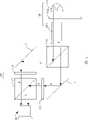
图1是本发明第一实施例的立体投影光学系统的结构示意图;1 is a schematic structural view of a stereoscopic projection optical system according to a first embodiment of the present invention;
图2是图1的立体投影光学系统的另一种结构的示意图;Fig. 2 is a schematic diagram of another structure of the stereoscopic projection optical system of Fig. 1;
图3是在图1的立体投影光学系统设置有多个偏振片的结构示意图;Fig. 3 is a structural schematic diagram of a plurality of polarizers arranged in the stereoscopic projection optical system of Fig. 1;
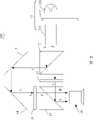
图4是本发明第二实施例的立体投影光学系统的结构示意图。FIG. 4 is a schematic structural diagram of a stereoscopic projection optical system according to a second embodiment of the present invention.
具体实施方式Detailed ways
为了对本发明作更进一步的说明,举以下较佳实施例并配合附图详细描述如下。In order to further illustrate the present invention, the following preferred embodiments are given and described in detail in conjunction with the accompanying drawings.
请参阅图1,为本发明所提供的第一实施例的立体投影光学系统100的结构示意图。该立体投影光学系统100包括沿光路方向依次设置的一光源组件11、一个第一偏振分束器12,分别设置于第一偏振分束器12不同出射光路上的第一、第二反射装置13、14,分别设置于所述第一、第二反射装置13、14的出射光路上的第一、第二穿透式空间光调制器15、16,一个设置于所述第一、第二穿透式空间光调制器15、16出射光路上的第二偏振分束器17,以及一个设置于第二偏振分束器17出射光路上的投影透镜18。Please refer to FIG. 1 , which is a schematic structural diagram of a stereoscopic projection
所述光源组件11包括依光路设置的一个照明光源111、一个色轮112以及一个积分器113。所述照明光源111发射包括显示彩色图像所需的红光(R)、绿光(G)和蓝光(B)的白光。该光源11可以为卤素灯、金属卤化物灯或氙灯等。在本实施例中,该光源11为卤素灯。所述色轮112包括红、绿、蓝三色区,其可在电机(图未示)的带动下高速旋转,以给投影光路配以各种色彩。所述积分器113用来均匀化和有效地使用光源11发出的光。The
所述第一偏振分束器(Polarization Beam Splitter,PBS)12用于将来自光源组件11的非偏振光变成偏振方向相互垂直的第一偏振光和第二偏振光,例如变成S偏振光和P偏振光。该S偏振光被该第一偏振分束器12反射,而P偏振光透过该第一偏振分束器12。该第一偏振分束器12可以为金属栅格型偏振片(Wire Grid Polarizer,简称WGP偏振片),也可以为偏振分光棱镜,在本实施例中,该第一偏振分束器12为偏振分光棱镜。The first polarizing beam splitter (Polarization Beam Splitter, PBS) 12 is used to change the unpolarized light from the
所述第一、第二反射装置13、14可以为一种反射镜,设置于所述第一偏振分束器12出射的光到下述的第二偏振分束器17入射的光的光路上,其可分别设置于第一偏振分束器12的两条出射光路上,也可以都设置于所述第一偏振分束器12出射的S、P偏振光的其中一条出射光的光路上,用于改变第一偏振分束器12出射的S、P偏振光的光路,以将该第一偏振分束器12的出射光耦合到第二偏振分束器17中。在本实施例中,该第一、第二反射装置13、14分别设置于第一偏振分束器12出射的S、P偏振光的出射光路上。如图2所示,为另一种第一、第二反射装置13、14的设置方法,其将该第一、第二反射装置13、14设置于第一偏振分束器12的S偏振光的出射光路上。当然可以想到的是,该第一、第二反射装置13、14还可设置于第一偏振分束器12的P偏振光的出射光路上。另外,需要说明的是,该第一、第二反射装置13、14可以设置于所述第一、第二穿透式空间光调制器15、16的入射光路上,也可以设置于其出射光路上。在本实施例中,该第一、第二反射装置设置于所述第一、第二穿透式空间光调制器15、16的入射光路上。The first and
所述第一、第二穿透式空间光调制器15、16结构及工作原理基本相同,下面以第一穿透式空间光调制器15为例来说明其结构及工作原理。The structures and working principles of the first and second transmissive
所述第一穿透式空间光调制器15可以为液晶显示装置(Liquid Crystal Dispaly,LCD)。所述第一穿透式空间光调制器15通过控制输入光的偏振状态来调制入射光并给入射光加入空间信息,形成包括该空间信息的经过调制的出射光。所述空间信息可以为所述第一穿透式空间光调制器15所加载的控制信号电压,该控制信号电压直接控制薄膜晶体管的开关状态,再利用该薄膜晶体管来控制所述液晶分子的偏转状态,而液晶分子具有明显的光学各向异性,能够控制来自入射光的光线,从而实现为入射光加载图像信号的目的。在本实施例中,该所述第一穿透式空间光调制器15对入射的S偏振光进行调制,并在所述S偏振光上叠加空间信息,以产生一个包括空间信息的出射光,即包括有空间信息的P偏振光。该P偏振光被该第一穿透式空间光调制器15发射并透过第二偏振分束器17发射出去。The first transmissive
所述第二穿透式空间光调制器16对入射的所述P偏振光进行调制,并在所述P偏振光上叠加空间信息,以产生一个包括空间信息的出射光,即包括有空间信息的S偏振光。该S偏振光被第二穿透式空间光调制器16发射并又被第二偏振分束器17反射而发射出去。The second transmissive
所述第二偏振分束器17与第一偏振分束器12的结构及工作原理基本相同,在此不再赘述。该第二偏振分束器17设置于第一、第二穿透式空间光调制器15、16的出射光的光路上。由所述第一穿透式空间光调制器15的出射光即P偏振光透过该第二偏振分束器17发射出去而进入下述的投影透镜16中。而第二穿透式空间光调制器16的出射光即S偏振光被该第二偏振分束器17反射而发射出去而进入投影透镜18中,以被投影到屏幕上(图未示)。The structure and working principle of the second polarizing
所述投影透镜18设置于第二偏振分束器17的出射光的光路上,用于将出射光所形成的图像放大,并将放大的图像投影到屏幕上。The
可以理解的是,为了进一步提高系统的对比度,还可以在上述的立体投影光学系统中加入多个偏振片19,如图3所示,该偏振片17可以让一定偏振方向的光通过,而吸收其它偏振方向的光,例如让P偏振光通过,而吸收S偏振光或者让S偏振光通过,而吸收P偏振光。该多个偏振片19的具体的放置位置可以为第一、第二偏振分束器12、17的光路之间的任意位置。在本实施例中在第一所述第一穿透式空间光调制器15与第二偏振分束器17之间以及第二穿透式空间光调制器16与第二偏振分束器17之间都设置有偏振片19。It can be understood that, in order to further improve the contrast of the system, a plurality of
请参阅图4,为本发明提供的第二实施例的投影光学系统200的结构示意图。该立体投影光学系统200包括沿光路方向依次设置的一光源组件21、一个第一偏振分束器22,分别设置于第一偏振分束器22不同出射光路上的第一、第二反射装置23、24,设置于所述第一、第二反射装置23、24的出射光路上的第一、第二穿透式空间光调制器25、26,一个设置于所述第一、第二穿透式空间光调制器25、26出射光路上的第二偏振分束器27以及一个设置于第二偏振分束器17出射光路上的投影透镜28。Please refer to FIG. 4 , which is a schematic structural diagram of a projection optical system 200 according to a second embodiment of the present invention. The stereoscopic projection optical system 200 includes a light source assembly 21, a first polarizing beam splitter 22 arranged in sequence along the direction of the optical path, and first and second reflecting devices 23 respectively arranged on different exiting optical paths of the first polarizing beam splitter 22. , 24, the first and second transmissive spatial light modulators 25 and 26 arranged on the outgoing light paths of the first and second reflecting devices 23 and 24, one of which is arranged on the first and second transmissive A second polarizing beam splitter 27 on the outgoing light path of the spatial light modulators 25 and 26 and a projection lens 28 arranged on the outgoing light path of the second
该第二实施例与第一实施例的不同在于所述第一、第二偏振分束器22、27对S偏振光及P偏振光的作用不同。在该第二实施例中,所述第一、第二偏振分束器22、27反射P偏振光,而可以让S偏振光透过各偏振分束器。而该P偏振光和S偏振光在各光学元件即第一偏振分束器22、第一、第二穿透式空间光调制器25、26以及第二偏振分束器27中的传输光路是相同的。The difference between the second embodiment and the first embodiment lies in that the effects of the first and second polarizing beam splitters 22 and 27 on S-polarized light and P-polarized light are different. In the second embodiment, the first and second polarizing beam splitters 22 and 27 reflect P-polarized light, but allow S-polarized light to pass through each polarizing beam splitter. The transmission optical paths of the P-polarized light and S-polarized light in each optical element, that is, the first polarizing beam splitter 22, the first and second transmissive spatial light modulators 25, 26 and the second polarizing beam splitter 27 are identical.
同理,为了进一步提高系统的对比度,还可以在第二实施例的立体投影光学系统200中加入多个偏振片29,其设置位置与第一实施例相同。Similarly, in order to further improve the contrast of the system, a plurality of polarizers 29 may also be added to the stereoscopic projection optical system 200 of the second embodiment, and the setting positions thereof are the same as those of the first embodiment.
上述的立体投影光学系统通过为第一、第二穿透式空间光调制器分别输入载有不同信息的光,而该第一、第二穿透式空间光调制器所形成的两幅图像分别以P偏振光和S偏振光或S偏振光和P偏振光通过投影透镜投影出去,当观看者的左右眼分别戴上检偏方向相互垂直的两片偏振片,就可以观察到立体的图像信息。The above-mentioned stereoscopic projection optical system respectively inputs light carrying different information to the first and second transmissive spatial light modulators, and the two images formed by the first and second transmissive spatial light modulators are respectively The P-polarized light and S-polarized light or S-polarized light and P-polarized light are projected through the projection lens. When the left and right eyes of the viewer are respectively equipped with two polarizers whose analyzing directions are perpendicular to each other, three-dimensional image information can be observed. .
另外,本领域技术人员还可在本发明精神内做其它变化,只要其不偏离本发明的技术效果,都应包含在本发明所要求保护的范围之内。In addition, those skilled in the art can also make other changes within the spirit of the present invention, as long as they do not deviate from the technical effect of the present invention, all should be included in the scope of protection claimed by the present invention.
Claims (10)
- [claim 1] a kind of stereo projection optical system, it is characterized in that: it comprises:One first polarization beam apparatus, this first polarization beam apparatus are used for incident light is divided into orthogonal first polarized light of polarization state and second polarized light;First, second penetration spatial light modulator is on the exit direction of corresponding respectively first, second polarized light that is arranged at described first polarization beam apparatus;One second polarization beam apparatus, this second polarization beam apparatus are arranged on the light path of emergent light of described first, second penetration spatial light modulator;Throwed into the first penetration spatial light modulator from first polarized light of the described first polarization beam apparatus outgoing, this first penetration spatial light modulator is modulated into second polarized light emission with this first polarized light and goes out, and launches through second polarization beam apparatus;Throwed into the second penetration spatial light modulator from second polarized light of the described first polarization beam apparatus outgoing, this second penetration spatial light modulator is modulated into first polarized light emission with this second polarized light and goes out, and this first polarized light is gone out through the second polarization beam apparatus back reflection.
- [claim 2] stereo projection optical system as claimed in claim 1 is characterized in that: described first, second polarization beam apparatus is a metal grate type polaroid.
- [claim 3] stereo projection optical system as claimed in claim 1 is characterized in that: described first, second polarization beam apparatus is a polarization splitting prism.
- [claim 4] stereo projection optical system as claimed in claim 1 is characterized in that: described first, second penetration spatial light modulator is a liquid crystal indicator.
- [claim 5] stereo projection optical system as claimed in claim 1 is characterized in that: described first polarized light is a kind of in S polarized light and the P polarized light.
- [claim 6] stereo projection optical system as claimed in claim 5 is characterized in that: when first polarized light was the S polarized light, second polarized light was the P polarized light.
- [claim 7] stereo projection optical system as claimed in claim 5 is characterized in that: when first polarized light was the P polarized light, second polarized light was the S polarized light.
- [claim 8] stereo projection optical system as claimed in claim 1, it is characterized in that: described stereo projection optical system also comprises at least two reflection units, the emergent light that these two reflection units are arranged at described first polarization beam apparatus is used for the emergent light of first polarization beam apparatus is coupled to second polarization beam apparatus on the light path of the incident light of second polarization beam apparatus.
- [claim 9] stereo projection optical system as claimed in claim 1, it is characterized in that: described stereo projection optical system also comprises a projecting lens that is arranged on the described second polarization beam apparatus emergent light direction, is used for the formed image of emergent light is amplified.
- [claim 10] stereo projection optical system as claimed in claim 1 is characterized in that: described stereo projection optical system also comprises a plurality of polaroids, and these a plurality of polaroids are arranged at respectively between first polarization beam apparatus and the second polarization beam apparatus light path.
Priority Applications (2)
| Application Number | Priority Date | Filing Date | Title |
|---|---|---|---|
| CNA2007102014865ACN101377571A (en) | 2007-08-28 | 2007-08-28 | Stereo projection optical system |
| US11/952,970US8077196B2 (en) | 2007-08-28 | 2007-12-07 | Stereo projection optical system |
Applications Claiming Priority (1)
| Application Number | Priority Date | Filing Date | Title |
|---|---|---|---|
| CNA2007102014865ACN101377571A (en) | 2007-08-28 | 2007-08-28 | Stereo projection optical system |
Publications (1)
| Publication Number | Publication Date |
|---|---|
| CN101377571Atrue CN101377571A (en) | 2009-03-04 |
Family
ID=40406784
Family Applications (1)
| Application Number | Title | Priority Date | Filing Date |
|---|---|---|---|
| CNA2007102014865APendingCN101377571A (en) | 2007-08-28 | 2007-08-28 | Stereo projection optical system |
Country Status (2)
| Country | Link |
|---|---|
| US (1) | US8077196B2 (en) |
| CN (1) | CN101377571A (en) |
Cited By (9)
| Publication number | Priority date | Publication date | Assignee | Title |
|---|---|---|---|---|
| CN102004388A (en)* | 2010-10-15 | 2011-04-06 | 天津峰景光电科技有限公司 | Three-dimensional miniature projector module |
| CN102325242A (en)* | 2011-04-08 | 2012-01-18 | 香港应用科技研究院有限公司 | Multi-image projection device |
| CN102483520A (en)* | 2009-06-29 | 2012-05-30 | 瑞尔D股份有限公司 | Stereoscopic projection system employing spatial multiplexing at an intermediate image plane |
| CN102566218A (en)* | 2012-02-03 | 2012-07-11 | 上海广擎光电科技有限公司 | Dual-chip passive polarized type three-dimensional projection system |
| WO2012146043A1 (en)* | 2011-04-26 | 2012-11-01 | 浙江亿思达显示科技有限公司 | 3d optical projection system and dual-chip beam splitting and combining module thereof |
| CN103454778A (en)* | 2013-09-16 | 2013-12-18 | 曹乃元 | Naked-eye 3D projection system |
| CN110146986A (en)* | 2019-01-14 | 2019-08-20 | 深圳珑璟光电技术有限公司 | An augmented reality display optical system |
| CN113495374A (en)* | 2020-03-20 | 2021-10-12 | 中国科学院西安光学精密机械研究所 | Method and system for improving diffraction efficiency of acousto-optic tunable filter |
| CN118938489A (en)* | 2024-08-30 | 2024-11-12 | 黑龙江天有为电子股份有限公司 | Optical system and HUD device for naked-eye 3D imaging |
Families Citing this family (26)
| Publication number | Priority date | Publication date | Assignee | Title |
|---|---|---|---|---|
| ES2428693T3 (en) | 2003-02-12 | 2013-11-08 | The Procter & Gamble Company | Absorbent core for an absorbent article |
| EP1913914B2 (en) | 2003-02-12 | 2014-08-06 | The Procter and Gamble Company | Absorbent core for an absorbent article |
| CA2838432C (en) | 2011-06-10 | 2018-02-27 | The Procter & Gamble Company | Absorbent structure for absorbent articles |
| DE202012013608U1 (en) | 2011-06-10 | 2018-04-30 | The Procter & Gamble Company | Absorption structure for absorbent article |
| PL3284449T3 (en) | 2011-06-10 | 2020-03-31 | The Procter & Gamble Company | Disposable diapers |
| JP5940655B2 (en) | 2011-06-10 | 2016-06-29 | ザ プロクター アンド ギャンブル カンパニー | Absorbent core for disposable absorbent articles |
| MX348890B (en) | 2012-11-13 | 2017-07-03 | Procter & Gamble | Absorbent articles with channels and signals. |
| PL2740449T3 (en) | 2012-12-10 | 2019-07-31 | The Procter & Gamble Company | Absorbent article with high absorbent material content |
| US8979815B2 (en) | 2012-12-10 | 2015-03-17 | The Procter & Gamble Company | Absorbent articles with channels |
| JP5618032B1 (en)* | 2013-01-25 | 2014-11-05 | パナソニック株式会社 | Stereo camera |
| DE202014011107U1 (en) | 2013-06-14 | 2017-12-15 | The Procter & Gamble Company | When wet, channels forming absorbent article and absorbent core |
| US9987176B2 (en) | 2013-08-27 | 2018-06-05 | The Procter & Gamble Company | Absorbent articles with channels |
| US9789011B2 (en) | 2013-08-27 | 2017-10-17 | The Procter & Gamble Company | Absorbent articles with channels |
| US11207220B2 (en) | 2013-09-16 | 2021-12-28 | The Procter & Gamble Company | Absorbent articles with channels and signals |
| JP6169800B2 (en) | 2013-09-16 | 2017-07-26 | ザ プロクター アンド ギャンブル カンパニー | Absorbent articles with channels and labels |
| EP2851048B1 (en) | 2013-09-19 | 2018-09-05 | The Procter and Gamble Company | Absorbent cores having material free areas |
| US9789009B2 (en) | 2013-12-19 | 2017-10-17 | The Procter & Gamble Company | Absorbent articles having channel-forming areas and wetness indicator |
| ES2643577T3 (en) | 2014-05-27 | 2017-11-23 | The Procter & Gamble Company | Absorbent core with absorbent material design |
| EP2949300B1 (en) | 2014-05-27 | 2017-08-02 | The Procter and Gamble Company | Absorbent core with absorbent material pattern |
| US10736795B2 (en) | 2015-05-12 | 2020-08-11 | The Procter & Gamble Company | Absorbent article with improved core-to-backsheet adhesive |
| JP6743057B2 (en) | 2015-05-29 | 2020-08-19 | ザ プロクター アンド ギャンブル カンパニーThe Procter & Gamble Company | Absorbent article having channels and wetness indicators |
| EP3167859B1 (en) | 2015-11-16 | 2020-05-06 | The Procter and Gamble Company | Absorbent cores having material free areas |
| EP3238676B1 (en) | 2016-04-29 | 2019-01-02 | The Procter and Gamble Company | Absorbent core with profiled distribution of absorbent material |
| EP3238678B1 (en) | 2016-04-29 | 2019-02-27 | The Procter and Gamble Company | Absorbent core with transversal folding lines |
| US11153541B2 (en) | 2018-08-31 | 2021-10-19 | Sony Corporation | Illuminator and display apparatus |
| CN109188700B (en)* | 2018-10-30 | 2021-05-11 | 京东方科技集团股份有限公司 | Optical display system and AR/VR display device |
Family Cites Families (9)
| Publication number | Priority date | Publication date | Assignee | Title |
|---|---|---|---|---|
| KR100197833B1 (en) | 1995-12-29 | 1999-06-15 | 윤종용 | Three dimentional television adopting double scan mode |
| EP1337117A1 (en) | 2002-01-28 | 2003-08-20 | Thomson Licensing S.A. | Stereoscopic projection system |
| JP2004126496A (en) | 2002-08-05 | 2004-04-22 | Hitachi Ltd | Optical unit and projection type image display device using the same |
| EP1610566A1 (en)* | 2004-06-25 | 2005-12-28 | Sony Deutschland GmbH | Imaging unit for color projection engine comprising reflective displays |
| US7261418B2 (en)* | 2004-11-12 | 2007-08-28 | 3M Innovative Properties Company | Projection apparatus |
| TWI286226B (en) | 2006-01-03 | 2007-09-01 | Coretronic Corp | Light source module and optical projection apparatus |
| WO2008003163A1 (en)* | 2006-07-02 | 2008-01-10 | Simon Andrew Boothroyd | Image-combining device and projection display apparatus having image-combining devices incorporated therein |
| US20080231953A1 (en)* | 2007-03-22 | 2008-09-25 | Young Garrett J | System and Method for LED Polarization Recycling |
| CN101377572A (en)* | 2007-08-28 | 2009-03-04 | 鸿富锦精密工业(深圳)有限公司 | Stereo projection optical system |
- 2007
- 2007-08-28CNCNA2007102014865Apatent/CN101377571A/enactivePending
- 2007-12-07USUS11/952,970patent/US8077196B2/ennot_activeExpired - Fee Related
Cited By (14)
| Publication number | Priority date | Publication date | Assignee | Title |
|---|---|---|---|---|
| CN102483520B (en)* | 2009-06-29 | 2014-05-28 | 瑞尔D股份有限公司 | Stereoscopic projection system employing spatial multiplexing at an intermediate image plane |
| CN102483520A (en)* | 2009-06-29 | 2012-05-30 | 瑞尔D股份有限公司 | Stereoscopic projection system employing spatial multiplexing at an intermediate image plane |
| CN102004388A (en)* | 2010-10-15 | 2011-04-06 | 天津峰景光电科技有限公司 | Three-dimensional miniature projector module |
| CN102325242A (en)* | 2011-04-08 | 2012-01-18 | 香港应用科技研究院有限公司 | Multi-image projection device |
| CN102325242B (en)* | 2011-04-08 | 2013-07-17 | 香港应用科技研究院有限公司 | Multi-image projection device |
| WO2012146043A1 (en)* | 2011-04-26 | 2012-11-01 | 浙江亿思达显示科技有限公司 | 3d optical projection system and dual-chip beam splitting and combining module thereof |
| US9279996B2 (en) | 2011-04-26 | 2016-03-08 | Zhejiang Estar Display Tech Co., Ltd. | 3D projection optical system and dual-chip light splitting and light combining module thereof |
| CN102566218A (en)* | 2012-02-03 | 2012-07-11 | 上海广擎光电科技有限公司 | Dual-chip passive polarized type three-dimensional projection system |
| CN103454778B (en)* | 2013-09-16 | 2015-09-23 | 曹乃元 | Bore hole 3D optical projection system |
| CN103454778A (en)* | 2013-09-16 | 2013-12-18 | 曹乃元 | Naked-eye 3D projection system |
| CN110146986A (en)* | 2019-01-14 | 2019-08-20 | 深圳珑璟光电技术有限公司 | An augmented reality display optical system |
| CN113495374A (en)* | 2020-03-20 | 2021-10-12 | 中国科学院西安光学精密机械研究所 | Method and system for improving diffraction efficiency of acousto-optic tunable filter |
| CN118938489A (en)* | 2024-08-30 | 2024-11-12 | 黑龙江天有为电子股份有限公司 | Optical system and HUD device for naked-eye 3D imaging |
| CN118938489B (en)* | 2024-08-30 | 2025-03-14 | 黑龙江天有为电子股份有限公司 | Optical system for naked eye 3D imaging and HUD equipment |
Also Published As
| Publication number | Publication date |
|---|---|
| US8077196B2 (en) | 2011-12-13 |
| US20090058994A1 (en) | 2009-03-05 |
Similar Documents
| Publication | Publication Date | Title |
|---|---|---|
| CN101377571A (en) | Stereo projection optical system | |
| CN101408675B (en) | Stereo projection optical system | |
| CN101398536B (en) | Stereo projection optical system | |
| CN101408677B (en) | Stereo projection optical system | |
| US8482549B2 (en) | Mutiple image projection apparatus | |
| CN101377572A (en) | Stereo projection optical system | |
| CN107889552B (en) | High-brightness image display device using modulator asymmetric driver and method of operation thereof | |
| KR20090100361A (en) | 2D / 3D projector with rotating translucent cylinder for alternating polarization | |
| CN101408678A (en) | Stereo projection optical system | |
| TWI357986B (en) | Optical system for stereo projection | |
| CN101373275A (en) | Stereo projection optical system | |
| CN101398537A (en) | Stereo projection optical system | |
| TW200916828A (en) | Optical system for stereo projection | |
| JP4155275B2 (en) | Image display device | |
| JP6028914B2 (en) | Image display system | |
| US8888292B2 (en) | Projection apparatus for providing multiple viewing angle images | |
| US6899429B2 (en) | Optical process unit, image generation system using the same and optical process method of the same | |
| TWI352216B (en) | Stereo projection optical system | |
| CN101408676A (en) | Stereo projection optical system | |
| JP5759288B2 (en) | Polarization modulator and image projection apparatus | |
| TWI359284B (en) | Optical system for stereo projection | |
| KR20150101153A (en) | stereoscopic display device and driving method thereof using polarization beam splitter | |
| JP2005043656A (en) | Projection solid image display device | |
| CN101393322A (en) | Stereo projection optical system | |
| TWI356191B (en) | Optical system for stereo projection |
Legal Events
| Date | Code | Title | Description |
|---|---|---|---|
| C06 | Publication | ||
| PB01 | Publication | ||
| C10 | Entry into substantive examination | ||
| SE01 | Entry into force of request for substantive examination | ||
| C02 | Deemed withdrawal of patent application after publication (patent law 2001) | ||
| WD01 | Invention patent application deemed withdrawn after publication | Open date:20090304 |