CN101361252A - Independent device for generating electrical energy - Google Patents
Independent device for generating electrical energyDownload PDFInfo
- Publication number
- CN101361252A CN101361252ACNA2006800515726ACN200680051572ACN101361252ACN 101361252 ACN101361252 ACN 101361252ACN A2006800515726 ACNA2006800515726 ACN A2006800515726ACN 200680051572 ACN200680051572 ACN 200680051572ACN 101361252 ACN101361252 ACN 101361252A
- Authority
- CN
- China
- Prior art keywords
- magnetic circuit
- central opening
- coil
- excitation coil
- arm
- Prior art date
- Legal status (The legal status is an assumption and is not a legal conclusion. Google has not performed a legal analysis and makes no representation as to the accuracy of the status listed.)
- Granted
Links
Images


Classifications
- H—ELECTRICITY
- H02—GENERATION; CONVERSION OR DISTRIBUTION OF ELECTRIC POWER
- H02K—DYNAMO-ELECTRIC MACHINES
- H02K35/00—Generators with reciprocating, oscillating or vibrating coil system, magnet, armature or other part of the magnetic circuit
- H02K35/02—Generators with reciprocating, oscillating or vibrating coil system, magnet, armature or other part of the magnetic circuit with moving magnets and stationary coil systems
Landscapes
- Engineering & Computer Science (AREA)
- Power Engineering (AREA)
- Reciprocating, Oscillating Or Vibrating Motors (AREA)
- Near-Field Transmission Systems (AREA)
- Electromagnets (AREA)
Abstract
Description
Translated fromChinese技术领域technical field
本发明涉及一种用于产生电能的独立装置。本发明的装置利用通过感应线圈的磁通量的变化产生电流。本发明还涉及由用于产生电能的独立装置提供能量的远程控制装置。The invention relates to a self-contained device for generating electrical energy. The device of the present invention utilizes changes in magnetic flux through an induction coil to generate an electric current. The invention also relates to a remote control device powered by a separate device for generating electrical energy.
背景技术Background technique
在以下描述中,术语“用于产生电能的独立装置”用以表示在不使用电流源以及不与电网相连,即无线的情况下能够产生电流的装置。In the following description, the term "stand-alone device for generating electrical energy" is used to denote a device capable of generating electric current without using a current source and without being connected to the grid, ie wirelessly.
美国专利申请2003/048018披露了一种发电机,其包括配有多个磁导体的定子,由延伸通过每个磁导体的绕组构成的电导体和包含多个永磁体的移动部分,该移动部分能够相对于定子移动以在绕组中产生电流。每个磁导体通过永磁体形成绕部分绕组延伸的磁路。在该文献中,产生的磁通量被分成两部分并因此使得绕组中获得的磁通变化不足以产生具有足够强度的电流。US patent application 2003/048018 discloses an electrical generator comprising a stator with a plurality of magnetic conductors, an electrical conductor consisting of a winding extending through each magnetic conductor and a moving part containing a plurality of permanent magnets, the moving part Can move relative to the stator to generate current in the windings. Each magnetic conductor forms a magnetic circuit extending around the partial winding through a permanent magnet. In this document, the generated magnetic flux is divided into two parts and thus the variation of the magnetic flux obtained in the winding is not sufficient to generate a current with sufficient intensity.
从专利申请WO2004/093299还可了解到机械能量转变成电能的转换器。该转换器包括永磁体和软磁体元件,这两个形成磁路和围绕部分磁路的电线圈。软磁体元件和永磁体被安装以相对于彼此旋转,这样允许移动而在通过线圈的磁路中产生磁通变化,进而导致线圈中电流的产生。A converter for converting mechanical energy into electrical energy is also known from patent application WO 2004/093299. The converter consists of a permanent magnet and a soft magnetic element, both forming a magnetic circuit and an electric coil surrounding part of the magnetic circuit. The soft magnetic element and the permanent magnet are mounted to rotate relative to each other, which allows movement to produce a change in flux in the magnetic circuit through the coil, which in turn results in the generation of current in the coil.
文献WO2004/093299实现了转换器在独立能量开关中的应用,所述独立能量开关即不具有能源且是无线的开关。当开关被机械启动时,由通过线圈的磁通量变化产生的电流能够为无线电信号发射器供给能量。无线电信号被传送到远程接收器,其随后发生响应,以对电气设备进行开关。当开关离接收器非常远或者由于许多物体而与后者分开时,产生的无线电信号在各种情况下不总是足以到达接收器。为了提高转换器的性能,必须增加线圈的匝数,进而增加了开关的尺寸,并且在给定用于绕组的铜线的价钱的情况下,制造的成本增加了。The document WO 2004/093299 implements the use of a converter in a stand-alone energy switch, ie a switch that does not have an energy source and is wireless. When the switch is mechanically actuated, the electrical current generated by the change in magnetic flux through the coil powers the radio signal transmitter. The radio signal is transmitted to a remote receiver, which then responds to switch the electrical device on and off. When the switch is very far away from the receiver or is separated from the latter by many objects, the resulting radio signal is not always sufficient to reach the receiver in each case. To increase the performance of the converter, the number of turns of the coil must be increased, which in turn increases the size of the switch and, given the cost of the copper wire used for the windings, increases the cost of manufacture.
发明内容Contents of the invention
本发明的目的是提出一种用于产生电能的上述类型的装置,其具有增强的性能同时保持小的占用面积以及适度的成本。The object of the present invention is to propose a device of the above-mentioned type for generating electrical energy with enhanced performance while maintaining a small footprint and moderate costs.
该目的通过提供一种用于产生电能的独立装置而实现,该装置包括:This object is achieved by providing a self-contained device for generating electrical energy comprising:
设有中心开口的激励线圈,Excitation coil with central opening,
通过所述线圈的中心开口的磁路,该磁路由固定部分和移动部分构成,该移动部分能够相对于所述固定部分移动,以改变通过所述激励线圈的磁通量,由此在激励线圈内产生电流,A magnetic circuit through the central opening of the coil, which consists of a fixed part and a moving part which is movable relative to the fixed part to vary the magnetic flux passing through the excitation coil, thereby generating in the excitation coil current,
其中,所述磁路若干次通过的所述激励线圈的中心开口,形成至少一个环(loop)。Wherein, the central opening of the excitation coil through which the magnetic circuit passes several times forms at least one loop.
根据本发明的一具体特征,所述磁路两次通过所述激励线圈的中心开口,形成一个环。According to a particular feature of the invention, said magnetic circuit passes twice through the central opening of said excitation coil, forming a loop.
根据本发明的另一具体特征,所述磁路的固定部分两次通过所述激励线圈的中心开口,形成一个环。According to another particular feature of the invention, the fixed part of the magnetic circuit passes twice through the central opening of the excitation coil, forming a loop.
因此,在包括两次通过激励线圈形成其环的磁路的用于产生电能的装置中,提高了感应系数,并且因此根据关系式E=1/2·L·I2,线圈中存储的能量数量也提高了,在上述关系式中E是线圈中存储的能量,L是线圈的感应系数并且I是通过线圈的磁通量变化所产生的电流强度。Thus, in a device for generating electrical energy comprising a magnetic circuit which passes twice through the energized coil forming its loop, the inductance is increased and therefore according to the relation E=1/2·L·I2 , the energy stored in the coil Quantities are also raised, where E is the energy stored in the coil, L is the inductance of the coil and I is the current intensity produced by the change in magnetic flux through the coil in the above relation.
因此,在移动部分的操作速度给定并且线圈匝数相同的情况下,本发明装置中由于通过线圈的磁通量变化而产生的电流是磁路仅通过线圈一次的现有技术装置中产生的电流的2倍。因此,根据以上限定的关系式,本发明装置中线圈内存储的能量E也是现有技术装置中产生的能量的2倍。Therefore, given the operating speed of the moving part and the same number of turns of the coil, the current produced in the device of the present invention due to the change of the magnetic flux through the coil is smaller than that produced in the prior art device in which the magnetic circuit passes through the coil only once. 2 times. Therefore, according to the relationship defined above, the energy E stored in the coil in the device of the present invention is also twice the energy generated in the device of the prior art.
此外,用于产生磁路的铁磁材料,例如铁,比用于形成线圈匝的铜便宜很多。因此,利用增加使用的铁量来弥补最小化提高装置性能所需的铜的量,可以十分有利且节省成本。Furthermore, the ferromagnetic material used to create the magnetic circuit, such as iron, is much cheaper than the copper used to form the coil turns. Therefore, it may be advantageous and cost-effective to offset the need to minimize the amount of copper needed to improve device performance by increasing the amount of iron used.
磁路长度的增加根据其固有原理当然地会增加感应系数(同样通量下的较长长度的铁),因此根据上述已经定义的关系式E=1/2·L·I2,线圈中存储的能量可得以增加。The increase of the magnetic circuit length will of course increase the inductance according to its inherent principle (longer length of iron under the same flux), so according to the above-mentioned defined relationship E=1/2·L·I2 , the stored in the coil energy can be increased.
根据本发明,线圈能够恢复与通量变化以及该变化的速度相关联的能量。通过调节与通过线圈的磁通量的变化速度相关联的电压峰值,还可提高能量产生性能。磁通量的变化速度对应磁路的移动部分相对于磁路的固定部分的移动速度。According to the invention, the coil is able to recover the energy associated with the change in flux and the speed of this change. Energy generation performance may also be improved by adjusting the voltage peak associated with the rate of change of magnetic flux through the coil. The rate of change of the magnetic flux corresponds to the rate of movement of the moving part of the magnetic circuit relative to the fixed part of the magnetic circuit.
因此,在不增加尺寸和占用面积的情况下,本发明的装置相比于现有技术装置能够获得增强的性能,或获得与现有技术装置相当的性能但具有更小的尺寸和占用面积。Thus, the device of the present invention can achieve enhanced performance compared to prior art devices, or comparable performance to prior art devices but with a smaller size and footprint, without increasing size and footprint.
根据本发明的另一具体特征,所述固定部分包括与不相连的两个臂联接的座,所述两个臂为第一臂和第二臂,它们各自通过激励线圈的中心开口。According to another particular feature of the invention, said fixed portion comprises a seat coupled to two arms that are not connected, a first arm and a second arm, each passing through a central opening of the excitation coil.
因此,根据本发明,磁路的固定部分形成为三个单独的部分,即座和两个臂。在制造过程中,两个臂通过线圈的中心开口并且座的每个腿与臂的一端相连,这样得到极好的刚性整体子组件。所述臂可以嵌入构成线圈保持器的材料中。Thus, according to the invention, the fixed part of the magnetic circuit is formed in three separate parts, namely the seat and the two arms. During manufacture, the two arms pass through the central opening of the coil and each leg of the seat is connected to one end of the arms, resulting in an extremely rigid overall subassembly. The arms may be embedded in the material making up the coil holder.
根据本发明,在所述磁路中循环的磁场沿一路径行进,所述路径经过所述移动部分、第一臂、座和第二臂,并返回到移动部分,所述磁场沿同一方向在所述两个臂中通过。According to the invention, the magnetic field circulating in the magnetic circuit follows a path which passes through the moving part, the first arm, the seat and the second arm and returns to the moving part, the magnetic field in the same direction in The two arms pass through.
根据本发明的另一具体特征,每个臂具有形成为所述移动部分的终点挡板的自由端。According to another particular feature of the invention, each arm has a free end formed as an end stop of said moving part.
根据本发明的另一具体特征,所述座呈U形,包括跨过所述激励线圈的两个平行腿。所述座的平行腿各自包括例如用于接收臂的一端的槽口。According to another particular feature of the invention, said seat is U-shaped, comprising two parallel legs spanning said excitation coil. The parallel legs of the seat each comprise a notch, for example for receiving one end of an arm.
根据本发明的另一具体特征,所述移动部分包括能够进行旋转移动的移动永磁体。所述永磁体的旋转移动是例如在由终点挡板限定的两个极端位置之间进行的摇臂移动。所述终点挡板是例如由所述通过线圈的臂的自由端形成的。According to another particular feature of the invention, said mobile part comprises a mobile permanent magnet capable of rotational movement. The rotational movement of the permanent magnet is, for example, a rocker movement between two extreme positions defined by end stops. The end stop is for example formed by the free end of the arm passing through the coil.
有利地,所述移动部分装配在朝一个极端位置向该移动部分施力的弹性装置上。Advantageously, said moving part is fitted on elastic means biasing it towards one extreme position.
根据本发明的另一具体特征,所述移动部分呈H形,并由保持在两个平行的铁磁层之间的永磁体构成。According to another particular feature of the invention, said moving part is H-shaped and is composed of a permanent magnet held between two parallel ferromagnetic layers.
根据本发明的另一具体特征,所述永磁体具有垂直于所述两个铁磁层所限定的平面的磁化方向。According to another particular feature of the invention, said permanent magnet has a magnetization direction perpendicular to the plane defined by said two ferromagnetic layers.
根据本发明的另一具体特征,所述移动部分是手动操作的。所述装置是通过摇杆或按钮类型的开关操作的。所述移动部分还可以由位置探测器中的一机械装置移动。According to another particular feature of the invention, said moving part is manually operated. The device is operated by a rocker or button type switch. The moving part can also be moved by a mechanical device in the position detector.
根据本发明,所述装置可以利用微机电技术制造。According to the invention, the device can be manufactured using microelectromechanical technology.
本发明还涉及一种远程控制装置,其包括与远程接收器耦接的发射器和如前所述的用于产生电能的独立装置,该独立装置用于产生电流,以为所述发射器提供能量。The invention also relates to a remote control device comprising a transmitter coupled to a remote receiver and a separate device as described above for generating electrical power for generating an electrical current to power said transmitter .
附图说明Description of drawings
本发明的其它特征和优点在以下参照附图以示例方式给出的对实施例的详细描述中将变得明显,在附图中:Other features and advantages of the invention will become apparent from the following detailed description of embodiments given by way of example with reference to the accompanying drawings in which:
图1示出了由根据本发明的用于产生电能的独立装置提供能量的远程控制装置的子组件,Figure 1 shows sub-assemblies of a remote control device powered by a stand-alone device for generating electrical energy according to the invention,
图2以分解图示出了本发明装置中所用的磁路的固定部分,Figure 2 shows the stationary part of the magnetic circuit used in the device of the invention in an exploded view,
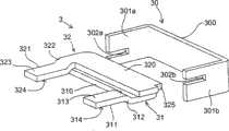
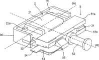
图3是示出了根据本发明的用于产生电能的独立装置的四分之三图(three-quarter view),所述装置安装在远程控制装置内,Figure 3 is a three-quarter view showing a stand-alone device for generating electrical energy according to the invention, said device being installed in a remote control device,
图4是从上方示出了根据本发明的用于产生电能的独立装置的示意图,所述装置安装在远程控制装置内,Figure 4 is a schematic view from above showing a self-contained device for generating electrical energy according to the invention, said device being installed in a remote control device,
图5是示出了本发明的分解图,Figure 5 is an exploded view showing the present invention,
图6A和6B是示出了分别处于第一极端位置和第二极端位置的移动部分的示意性正视图,6A and 6B are schematic front views showing the moving part in a first extreme position and a second extreme position, respectively,
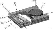
图7示意性示出了本发明装置的一实施例变型。FIG. 7 schematically shows a variant embodiment of the device according to the invention.
具体实施方式Detailed ways
在以下的描述中,术语“顶”和“底”以及所用的其他等效表示应在附图中以垂直方向的轴作为参考来理解。In the following description, the terms "top" and "bottom" and other equivalent expressions used should be understood with reference to the vertical axis in the drawings.
根据本发明的用于产生电能的独立装置1能够借助外部机械动作,例如手动,改变通过线圈2的磁通量,从而在激励线圈2中产生电流。The self-contained device 1 for generating electrical energy according to the invention is capable of changing the magnetic flux through the
上述装置1用于无线的且不具备内电流源的远程控制装置中。该远程控制装置例如可利用能够控制光的摇杆或按钮型开关手动操作,并可在空间内的各个位置处无限制地定位。远程控制装置特别地包括图1中所示的机械子组件。该机械子组件用于接收根据本发明的用于产生电能的独立装置1,并且还包括用于为产生电能的装置1传递机械能的操作设备6、7。远程控制装置还包括由上述装置1产生的电流供给能量以向远程接收器发送无线电信号的发射器(未示出),以及特别地包括存储根据本发明的装置1产生的电能的设备,如电容器,以便使在下游传递至发射器的电流量平稳的电子电路(未示出)。The device 1 described above is used in a remote control device that is wireless and does not have an internal current source. The remote control is manually operable, eg, with a rocker or push button type switch capable of controlling lights, and can be positioned without limitation at various positions within the space. The remote control device notably includes the mechanical subassembly shown in FIG. 1 . This mechanical subassembly is intended to receive the stand-alone device 1 for generating electrical energy according to the invention and also comprises operating devices 6 , 7 for transferring mechanical energy to the device 1 for generating electrical energy. The remote control device also includes a transmitter (not shown) powered by the electric current generated by the device 1 described above to send a radio signal to a remote receiver, and in particular a device for storing the electrical energy generated by the device 1 according to the invention, such as a capacitor , an electronic circuit (not shown) to smooth the amount of current delivered downstream to the emitter.
根据本发明用于产生电能的独立装置1还可实现为其他应用,例如位置探测器或机械压力传感器,其中产生和测量的电流量可用于确定是否施加了机械力。机械作用能够产生用于触发例如警报器或信号装置或如之前所述为无线电发射器供给能量的电流。The stand-alone device 1 for generating electrical energy according to the invention can also be realized in other applications, such as position detectors or mechanical pressure sensors, where the amount of electrical current generated and measured can be used to determine whether a mechanical force has been applied. The mechanical action can generate an electrical current that is used to trigger eg a siren or signaling device or to energize a radio transmitter as described above.
参照图2至6B,根据本发明的装置1特别地包括由固定部分3和移动部分5构成的磁路以及激励线圈2,通过该磁路能够计算磁场。这可以利用MEMS(微机电系统)技术实现。MEMS技术是公知的,其实现为叠置连续的多个层,其中一层例如是牺牲层,利用蚀刻随后去除该层以释放移动部分。Referring to FIGS. 2 to 6B , the device 1 according to the invention notably comprises a magnetic circuit composed of a
磁路中的磁通量由移动部分5相对于固定部分3的瞬时角位置限定,使得移动部分5相对于固定部分3的移动产生通过线圈2的磁通量变化,该变化在线圈中引发电流。由磁通量变化在线圈2的端子处产生的电压依赖于时间并因此依赖于移动部分5相对于固定部分3的移动速度。The magnetic flux in the magnetic circuit is defined by the instantaneous angular position of the moving
激励线圈2包括非磁性(amagnetic)材料制成的保持器20,在保持器上缠绕了由N匝导电线构成的线圈21(图3和4)。保持器20在纵轴(A)上形成中心开口,并调整开口的尺寸使得磁路能够若干次通过该开口。在附图中,磁路的固定部分3两次通过线圈2的中心开口,形成环。因此,磁路第一次通过线圈2的中心开口,随后绕线圈2缠绕以形成环,并且第二次通过线圈2的中心开口。激励线圈的保持器20包括筒固定部(barrel fixing)22a、22b,其用于接收线圈2的导电线的两端以使其与置于保持器20上的电子卡(未示出)相连。The
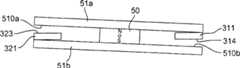
磁路的移动部分5例如是对称的H型,其例如包括保持在两个平行铁磁材料层51a、51b,即顶层51a和底层51b,之间的永磁体50。永磁体50固定在底层51a和顶层51b的内表面510a和510b上。该移动部分5装配成在垂直于保持器20中心开口纵轴(A)的水平旋转轴(R)上旋转。旋转轴(R)在图3和4中表示为圆柱件52,其结合至安装在移动部分5上的支撑件53,并与移动部分5结合旋转。永磁体在垂直于移动部分5的旋转轴(R)的垂直方向上,如上下方向上被南北极化(图6A和6B)。The moving
磁路的固定部分3由具有高磁导率的材料,如铁磁材料制成。参照图2,固定部分3包括跨过激励线圈2(图4)以形成环的U形座30。座30由此具有彼此平行并由中间芯部300分开的第一腿301a和第二腿301b。两个腿301a、301b沿平行于移动部分5的旋转轴(R)的方向延伸激励线圈2的两侧,而没有通过保持器20的中心开口。每个腿301a、301b的自由端具有槽口302a、302b。The
参照图2,磁路的固定部分3还包括分开、不相连且不同的第一臂31和第二臂32,一个臂是另一个的镜像。这些臂31、32为L形,并且各自具有从第一端开始的长分支310、320以及终止于第二自由端的短分支311、321。这些臂在两个分支的连接点还设有逐渐倾斜的部分312、322。这两个臂31、32的长分支310、320分别在两个平面上通过保持器20的中心开口,所述平面平行于线圈2的中心开口的纵轴(A)。第一臂31借助第一端与座30的第一腿301a相连,而第二臂32借助其第一端与座30的第二腿301b相连。在每个臂21、32的第一端上产生的对准不连续部(alignmentdiscontinuity)325能够使臂31、32接合在其连接的腿301a、301b的槽口302a、302b中。中心开口的外侧,每个臂31、32的倾斜部分312、322使短分支311、321返回到同一水平平面,移动部分5的旋转轴(R)也位于该平面内。每个臂31、32的第二端置于移动部分5的永磁体50的两侧,并位于移动部分5的两个铁磁层51a、51b之间。每个臂31、32的短分支311、321形成移动部分5的终点挡板,并限定出两个相对支承平台,即顶部支承平台313、323和底部支承平台314、324。移动部分5在每个臂31、32形成的终点挡板之间具有旋转自由度。Referring to Figure 2, the
根据本发明,在保持器20的中心开口内设置例如由塑性材料制成的适当引导装置,以引导每个臂31、32并使它们保持彼此相距足够距离,从而不会干扰磁路中磁场的循环,并避免臂31、32之间的泄漏。According to the invention, suitable guide means, for example made of plastic material, are provided in the central opening of the
因为座30设置成使得其两个腿301a、301b位于线圈2的两侧,所以臂31、32中循环的磁场总是沿相同方向通过线圈2的中心开口。因此,磁场沿相同方向两次通过激励线圈2的中心开口。如果磁路通过激励线圈的中心开口超过两次,则产生的磁场沿相同方向以与通过线圈的相同次数通过激励线圈的中心开口。Since the
因此根据本发明,磁路的固定部分3形成为三个单独的部分,即座30和两个臂31、32。在制造过程中,两个臂31、32通过线圈2的中心开口并且座30的每个腿301a、301b与臂31、32的第一端相连,这使得可以产生极好的刚性紧凑子组件。根据本发明,两个臂31、32还可嵌入形成激励线圈2的保持器20的材料中,以形成由线圈2和臂31、32构成的极好的刚性件。According to the invention, therefore, the
根据本发明,确定磁性材料制造的各种元件的截面,以使磁路在产生能量的独立装置1的使用范围内具有最小饱和度。According to the invention, the cross-sections of the various elements made of magnetic material are determined so that the magnetic circuit has a minimum degree of saturation within the range of use of the self-contained device 1 for generating energy.
移动部分5绕轴(R)进行摇臂移动,并具有由终点挡板限定的两个不同极端位置,移动部分5借助磁力保持在每个极端位置。当移动部分从其一个极端位置升起时,在超过中心平衡位置的情况下,由于磁效应而瞬间被吸引到另一极端位置。英国专利申请1 312 927中对该现象做了特别描述。The moving
在第一极端位置(图6a)上,移动部分5的底层51b的内表面510b被磁力吸靠于第一臂的短分支311的底部支承平台314,而移动部分5的顶层51a的内表面510a被磁力吸靠于第二臂32的短分支321的顶部支承平台323。In the first extreme position ( FIG. 6 a ), the
在第一极端位置上,磁路中循环的磁场沿以下路径行进:In the first extreme position, the magnetic field circulating in the magnetic circuit follows the following path:
永磁体50,
移动部分5的顶层51a,the
第二臂32,
座30的第二腿301b,the
座30的中间芯部300,the
座30的第一腿301a,the
第一臂31,
移动部分5的底层51b,the
永磁体50。
在第二极端位置(图6B)上,移动部分5的顶层51a的内表面510a被磁力吸靠于第一臂31的短分支311的顶部支承平台313,而移动部分5的底层51b的内表面510b被磁力吸靠于第二臂32的短分支321的底部支承平台324。In the second extreme position (FIG. 6B), the
在第二极极端位置上,磁路中循环的磁场沿以下相反路径行进:At the second pole extreme position, the magnetic field circulating in the magnetic circuit follows the following reverse path:
永磁体50,
移动部分5的顶层51a,the
第一臂31,
座30的第一腿301a,the
座30的中间芯部300,the
座30的第二腿301b,the
第二臂32,
移动部分5的底层51b,the
永磁体50。
因此,磁路中形成的磁场在通过线圈2的两个臂31、32中沿相同方向定向。Thus, the magnetic field formed in the magnetic circuit is oriented in the same direction in the two
在机械开关型应用中,弹簧板54(图3和4)一方面接合安装至装置的操作设备6、7(图1),而另一方面通过与支撑件53相连并具有三角形截面的构件55与移动部分5相连,支撑件本身安装在移动部分5上。确定弹簧板54的尺寸,使其在被供以一定量的机械能量时突然变型,从而以旋转方式操作移动部分。因此,在操作时,弹簧板54在引起移动部分5摇动之前能够将机械能量存储到一定的阈值。弹簧板54由此能够给予本发明装置1恒定的操作动态,其不依赖于用户所施加的机械压力。In a mechanical switch type application, the spring plate 54 ( FIGS. 3 and 4 ) engages on the one hand the operating device 6 , 7 ( FIG. 1 ) mounted to the device and on the other hand passes through a
在开关型的应用中,移动部分5的极端位置之一,例如第一极端位置(图6A)是稳定的平衡位置,而另一极端位置,即第二极端位置(图6B)是不稳定的。弹簧板54实际安装在弹性装置上,如弹簧(未示出),使得能够重新恢复根据本发明的装置1,并由此使移动部分5在移动之后系统地(systematically)返回到稳定的平衡位置。因此,弹簧板54的变形所产生的机械能量必须足以在移动部分5处于第一稳定极端位置时使其从支承平台314、323(图6A)脱离。In switch-type applications, one of the extreme positions of the moving
因此,在开关中,操作总是引起移动部分5在其第一极端位置和第二极端位置之间去和回。在去的移动中,产生通过线圈2的磁通量的第一变化并由此产生第一电流,而在回来的移动中,产生通过线圈2的磁通量的第二变化并由此产生第二电流。因此,单一的操作能够产生双倍的电能量。Thus, in a switch, operation always causes the moving
根据图7中所示的本发明装置的实施例变型,磁路包括固定部分3′和移动部分5′。在以上描述的装置中,固定部分3′包括两次通过线圈2的保持器中心开口的两个部分31′、32′。此外,固定部分3′包括位于线圈2外侧的两个不相连的部分,移动部分5′位于这两个部分之间。移动部分5′例如包括在其周边具有永磁体50′构成的部分的铁磁材料圆柱体。在磁路的固定部分3′的两个不相连的部分之间,该移动部分5′被操作以绕其旋转轴(R′)旋转。根据该变型,移动部分5’的旋转轴(R′)是垂直的,且垂直于线圈2保持器的中心开口的纵轴(A)。该变型的整体操作与之前描述的相同,也就是说,移动部分5′关于其轴(R′)的旋转移动产生通过线圈2的磁通量变换,进而导致电流的产生。According to an embodiment variant of the device of the invention shown in FIG. 7 , the magnetic circuit comprises a
显然,在不脱离本发明的精神范围的情况下,可以做出其他变型和细节上的改进,甚至可考虑使用等同装置。It is obvious that other modifications and improvements in detail may be made, and equivalent means may even be considered, without departing from the spirit and scope of the invention.
Claims (16)
Applications Claiming Priority (3)
| Application Number | Priority Date | Filing Date | Title |
|---|---|---|---|
| FR0553539 | 2005-11-22 | ||
| FR0553539AFR2893780A1 (en) | 2005-11-22 | 2005-11-22 | Electric energy generation device for e.g. supplying transmitter, has magnetic circuit formed of movable part and fixed part that traverses central opening of coil two times by forming loop, where circuit is made of ferromagnetic material |
| PCT/EP2006/067755WO2007060072A1 (en) | 2005-11-22 | 2006-10-25 | Stand-alone device for generating electrical energy |
Publications (2)
| Publication Number | Publication Date |
|---|---|
| CN101361252Atrue CN101361252A (en) | 2009-02-04 |
| CN101361252B CN101361252B (en) | 2012-07-18 |
Family
ID=36794915
Family Applications (1)
| Application Number | Title | Priority Date | Filing Date |
|---|---|---|---|
| CN2006800515726AExpired - Fee RelatedCN101361252B (en) | 2005-11-22 | 2006-10-25 | Stand-alone and remote-controlled devices for generating electrical energy |
Country Status (8)
| Country | Link |
|---|---|
| US (1) | US8148856B2 (en) |
| EP (1) | EP1952516A1 (en) |
| JP (1) | JP5128487B2 (en) |
| CN (1) | CN101361252B (en) |
| AU (1) | AU2006316662B2 (en) |
| CA (1) | CA2630554C (en) |
| FR (1) | FR2893780A1 (en) |
| WO (1) | WO2007060072A1 (en) |
Cited By (5)
| Publication number | Priority date | Publication date | Assignee | Title |
|---|---|---|---|---|
| CN102823061A (en)* | 2010-03-23 | 2012-12-12 | Zf腓德烈斯哈芬股份公司 | Radio switch |
| CN102823119A (en)* | 2010-03-23 | 2012-12-12 | Zf腓德烈斯哈芬股份公司 | Induction generator |
| CN102938600A (en)* | 2011-09-21 | 2013-02-20 | 武汉领普科技有限公司 | Staggering mesh-type magnetic power generation device |
| CN104883025A (en)* | 2015-06-12 | 2015-09-02 | 武汉领普科技有限公司 | Self-resetting generating device and switch |
| CN106899190A (en)* | 2015-12-21 | 2017-06-27 | 上海交通大学 | A kind of micro-vibration electricity energy harvester of utilization flux steering improve generating efficiency |
Families Citing this family (35)
| Publication number | Priority date | Publication date | Assignee | Title |
|---|---|---|---|---|
| DE102008003595B4 (en)* | 2008-01-09 | 2009-10-08 | Panasonic Electric Works Europe Ag | energy converters |
| DE102008003596A1 (en)* | 2008-01-09 | 2009-07-23 | Panasonic Electric Works Europe Ag | Switching device and method for switching on an electrical appliance |
| FR2928501B1 (en)* | 2008-03-04 | 2011-04-01 | Schneider Electric Ind Sas | DEVICE FOR GENERATING ENERGY WITH TWO MOVING PARTS |
| FR2953059B1 (en)* | 2009-11-25 | 2011-11-04 | Schneider Electric Ind Sas | REMOTE CONTROL DEVICE |
| FR2953659B1 (en)* | 2009-12-04 | 2011-12-23 | Schneider Electric Ind Sas | ELECTRIC POWER GENERATING DEVICE AND REMOTE CONTROL PROVIDED WITH SUCH A DEVICE |
| DE102011007397B4 (en)* | 2011-04-14 | 2016-03-10 | Hahn-Schickard-Gesellschaft für angewandte Forschung e.V. | Device for converting kinetic energy into electrical energy |
| JP5859763B2 (en)* | 2011-07-07 | 2016-02-16 | アルプス電気株式会社 | Power generation input device and electronic apparatus using the power generation input device |
| WO2013084409A1 (en)* | 2011-12-09 | 2013-06-13 | パナソニック株式会社 | Power generation device |
| US9343931B2 (en) | 2012-04-06 | 2016-05-17 | David Deak | Electrical generator with rotational gaussian surface magnet and stationary coil |
| DE102012220418A1 (en)* | 2012-11-09 | 2014-05-15 | Zf Friedrichshafen Ag | An induction generator and method for generating an electric current using an induction generator |
| DE102012220419A1 (en) | 2012-11-09 | 2014-05-15 | Zf Friedrichshafen Ag | An induction generator and method for generating an electric current using an induction generator |
| DE102012112897A1 (en)* | 2012-12-21 | 2014-07-10 | Eltako GmbH Schaltgeräte | radio switch |
| JP5979028B2 (en)* | 2013-01-31 | 2016-08-24 | オムロン株式会社 | Power generator, transmitter, switching device |
| JP6479011B2 (en)* | 2013-08-26 | 2019-03-06 | エンホウ リュウ | Self-powered wireless switch |
| FR3017007B1 (en) | 2014-01-27 | 2017-08-04 | Schneider Electric Ind Sas | SECURE ELECTRIC POWER SUPPLY SYSTEM |
| JP6198323B2 (en)* | 2014-02-05 | 2017-09-20 | アルプス電気株式会社 | Generator |
| FR3023648B1 (en) | 2014-07-09 | 2016-07-01 | Schneider Electric Ind Sas | EMERGENCY STOP DEVICE |
| WO2016143262A1 (en)* | 2015-03-09 | 2016-09-15 | パナソニックIpマネジメント株式会社 | Power generation device |
| JP6558048B2 (en) | 2015-04-24 | 2019-08-14 | ミツミ電機株式会社 | Power switch |
| CN110908320B (en)* | 2015-05-29 | 2022-05-10 | 广东易百珑智能科技有限公司 | Self-generating wireless switch and application thereof |
| US9843248B2 (en)* | 2015-06-04 | 2017-12-12 | David Deak, SR. | Rocker action electric generator |
| CN106469630B (en)* | 2015-08-18 | 2019-03-12 | 泰科电子(深圳)有限公司 | Polarity relay |
| CN205081657U (en)* | 2015-10-23 | 2016-03-09 | 瑞声光电科技(常州)有限公司 | Vibration motor |
| JP6058773B2 (en)* | 2015-10-27 | 2017-01-11 | アルプス電気株式会社 | Electronic equipment using a power generation input device |
| CN105469568A (en)* | 2015-11-30 | 2016-04-06 | 南京邮电大学 | Self-powered wireless switch |
| CN107852080A (en)* | 2016-02-04 | 2018-03-27 | 廖淑辉 | Self-generating remote controller and its application |
| US10673313B2 (en)* | 2016-02-24 | 2020-06-02 | YuanFang LIU | Self-powered wireless switch |
| FR3071678B1 (en)* | 2017-09-28 | 2019-09-13 | Commissariat A L'energie Atomique Et Aux Energies Alternatives | ELECTROMAGNETIC ENERGY CONVERTER |
| EP3704785B1 (en) | 2017-10-30 | 2024-07-03 | WePower Technologies LLC | Magnetic momentum transfer generator |
| US11368079B2 (en) | 2019-11-06 | 2022-06-21 | David Deak, SR. | Offset triggered cantilever actuated generator |
| DE102019127605A1 (en)* | 2019-10-14 | 2021-04-15 | Enocean Gmbh | Electromagnetic energy converter |
| US11973391B2 (en) | 2019-11-21 | 2024-04-30 | Wepower Technologies Llc | Tangentially actuated magnetic momentum transfer generator |
| CN112614326A (en)* | 2020-12-09 | 2021-04-06 | 无锡迪富智能电子股份有限公司 | Self-generating remote controller for intelligent closestool |
| FR3122049B1 (en) | 2021-04-15 | 2023-03-03 | Commissariat Energie Atomique | Electromagnetic device for converting mechanical energy into electrical energy |
| CN119231867B (en)* | 2024-11-28 | 2025-03-14 | 克瑞科技(东莞)有限公司 | Linear motor for small household appliances |
Family Cites Families (12)
| Publication number | Priority date | Publication date | Assignee | Title |
|---|---|---|---|---|
| FR2093358A5 (en)* | 1970-04-03 | 1972-01-28 | Zentronik Veb K | |
| EP0303054B1 (en)* | 1984-04-04 | 1993-06-09 | Omron Tateisi Electronics Co. | Electromagnetic drive and polarized relay |
| KR950000241B1 (en)* | 1990-01-12 | 1995-01-12 | 배연수 | Magnetic circuit and induction method of rotation apparatus for electric power |
| JPH04197041A (en)* | 1990-11-27 | 1992-07-16 | Matsushita Electric Works Ltd | Charger for portable electric device |
| US5349256A (en)* | 1993-04-23 | 1994-09-20 | Holliday Jeffrey C | Linear transducer |
| DE19620880A1 (en)* | 1996-05-23 | 1997-11-27 | Brandestini Marco | Method and device for generating electrical energy for operating small electrical appliances |
| JP3106144B2 (en)* | 1999-03-30 | 2000-11-06 | 昭 松下 | Composite magnetic material electromotive force generator |
| SE521607C2 (en)* | 2000-04-07 | 2003-11-18 | Abb Ab | A linear electric machine |
| SE524861C2 (en)* | 2002-08-14 | 2004-10-12 | Abb Ab | An electric machine and its use |
| FR2847071B1 (en)* | 2002-11-13 | 2004-12-24 | Schneider Electric Ind Sas | ELECTROMAGNETIC ACTUATOR |
| DE10301192A1 (en)* | 2003-01-15 | 2004-07-29 | Robert Bosch Gmbh | Electrical power supply to a tire pressure sensor is provided by voltage induced in coil when wheel rotates |
| DE10315765C5 (en)* | 2003-04-07 | 2021-03-11 | Enocean Gmbh | Use of an electromagnetic energy converter |
- 2005
- 2005-11-22FRFR0553539Apatent/FR2893780A1/ennot_activeWithdrawn
- 2006
- 2006-10-25USUS12/094,242patent/US8148856B2/enactiveActive
- 2006-10-25CNCN2006800515726Apatent/CN101361252B/ennot_activeExpired - Fee Related
- 2006-10-25WOPCT/EP2006/067755patent/WO2007060072A1/enactiveApplication Filing
- 2006-10-25AUAU2006316662Apatent/AU2006316662B2/ennot_activeCeased
- 2006-10-25JPJP2008541678Apatent/JP5128487B2/ennot_activeExpired - Fee Related
- 2006-10-25CACA2630554Apatent/CA2630554C/ennot_activeExpired - Fee Related
- 2006-10-25EPEP06807535Apatent/EP1952516A1/ennot_activeCeased
Cited By (8)
| Publication number | Priority date | Publication date | Assignee | Title |
|---|---|---|---|---|
| CN102823061A (en)* | 2010-03-23 | 2012-12-12 | Zf腓德烈斯哈芬股份公司 | Radio switch |
| CN102823119A (en)* | 2010-03-23 | 2012-12-12 | Zf腓德烈斯哈芬股份公司 | Induction generator |
| CN102823119B (en)* | 2010-03-23 | 2015-02-25 | Zf腓德烈斯哈芬股份公司 | Induction generator |
| CN102823061B (en)* | 2010-03-23 | 2015-05-20 | Zf腓德烈斯哈芬股份公司 | Radio switch |
| US9214716B2 (en) | 2010-03-23 | 2015-12-15 | Zf Friedrichshafen Ag | Radio switch |
| CN102938600A (en)* | 2011-09-21 | 2013-02-20 | 武汉领普科技有限公司 | Staggering mesh-type magnetic power generation device |
| CN104883025A (en)* | 2015-06-12 | 2015-09-02 | 武汉领普科技有限公司 | Self-resetting generating device and switch |
| CN106899190A (en)* | 2015-12-21 | 2017-06-27 | 上海交通大学 | A kind of micro-vibration electricity energy harvester of utilization flux steering improve generating efficiency |
Also Published As
| Publication number | Publication date |
|---|---|
| EP1952516A1 (en) | 2008-08-06 |
| FR2893780A1 (en) | 2007-05-25 |
| CA2630554A1 (en) | 2007-05-31 |
| AU2006316662B2 (en) | 2010-08-12 |
| CA2630554C (en) | 2015-04-21 |
| US8148856B2 (en) | 2012-04-03 |
| JP2009516802A (en) | 2009-04-23 |
| US20080315595A1 (en) | 2008-12-25 |
| JP5128487B2 (en) | 2013-01-23 |
| WO2007060072A1 (en) | 2007-05-31 |
| AU2006316662A1 (en) | 2007-05-31 |
| CN101361252B (en) | 2012-07-18 |
Similar Documents
| Publication | Publication Date | Title |
|---|---|---|
| CN101361252B (en) | Stand-alone and remote-controlled devices for generating electrical energy | |
| JP5824647B2 (en) | Power generator | |
| JP4225792B2 (en) | Inductive voltage control circuit | |
| JP2017085885A (en) | Induction generator and manufacturing method thereof | |
| AU2012200662B2 (en) | Wireless switching device | |
| US9985509B2 (en) | Induction generator and method for generating an electric current using an induction generator | |
| JP2009100523A (en) | Permanent magnet element and oscillating generator, and acceleration sensor | |
| AU2011295275B2 (en) | Device for detecting and signaling a change in the state of a push button | |
| US6171886B1 (en) | Method of making integrated hybrid silicon-based micro-actuator devices | |
| CN106716565B (en) | Electromagnetic adjustment equipment | |
| WO2014021196A1 (en) | Power generation device | |
| US6229300B1 (en) | Wiegand tilt sensor | |
| JP2012249442A (en) | Oscillating generator | |
| CN100369173C (en) | Linear Magnetic Drive | |
| JP2004360747A (en) | Spring constant variable magnetic spring device | |
| JP2005250284A (en) | Stage device and camera shake correction device using the stage device | |
| JPH08205508A (en) | Linear solenoid | |
| JPS591055B2 (en) | magnetic actuator device | |
| KR102230962B1 (en) | Actuator | |
| JP2006246691A (en) | Linear oscillating actuator module | |
| JP2005210609A (en) | Actuator | |
| JP2009290923A (en) | Magnetostriction actuator | |
| JP2007252166A (en) | Actuator | |
| TW200600956A (en) | Focusing structure of image device |
Legal Events
| Date | Code | Title | Description |
|---|---|---|---|
| C06 | Publication | ||
| PB01 | Publication | ||
| C10 | Entry into substantive examination | ||
| SE01 | Entry into force of request for substantive examination | ||
| C14 | Grant of patent or utility model | ||
| GR01 | Patent grant | ||
| CF01 | Termination of patent right due to non-payment of annual fee | Granted publication date:20120718 Termination date:20201025 | |
| CF01 | Termination of patent right due to non-payment of annual fee |