CN101357051A - Suction Inlet Assembly for Vacuum Cleaners - Google Patents
Suction Inlet Assembly for Vacuum CleanersDownload PDFInfo
- Publication number
- CN101357051A CN101357051ACNA2008101103442ACN200810110344ACN101357051ACN 101357051 ACN101357051 ACN 101357051ACN A2008101103442 ACNA2008101103442 ACN A2008101103442ACN 200810110344 ACN200810110344 ACN 200810110344ACN 101357051 ACN101357051 ACN 101357051A
- Authority
- CN
- China
- Prior art keywords
- vacuum cleaner
- extension tube
- cleaner
- main body
- assembly
- Prior art date
- Legal status (The legal status is an assumption and is not a legal conclusion. Google has not performed a legal analysis and makes no representation as to the accuracy of the status listed.)
- Pending
Links
Images


Landscapes
- Electric Vacuum Cleaner (AREA)
- Nozzles For Electric Vacuum Cleaners (AREA)
Abstract
Translated fromChinese
Description
Translated fromChinese相关申请的交叉参考Cross References to Related Applications
本申请要求于2007年8月14日向美国专利商标局提交的申请号为No.60/964676的美国专利申请,以及于2007年9月14日和2007年8月2日向韩国知识产权局提交的申请号为Nos.2007-0093884和Nos.2007-0077662的韩国专利申请的优先权,其整个公开内容通过参考包含于此。This application claims U.S. Patent Application No. 60/964676 filed with the United States Patent and Trademark Office on August 14, 2007, and filed with the Korean Intellectual Property Office on September 14, 2007 and August 2, 2007 The priority of Korean Patent Application Nos. 2007-0093884 and Nos. 2007-0077662, the entire disclosure of which is hereby incorporated by reference.
技术领域technical field
本发明涉及一种真空吸尘器,更具体的是,本发明涉及一种真空吸尘器,其能够通过使用由吸尘器主体内部驱动的电机产生的吸力从待清洁表面吸入带有灰尘的空气,从吸入的空气中过滤灰尘,并将净化的空气排放至吸尘器主体外部。The present invention relates to a vacuum cleaner, and more particularly, to a vacuum cleaner capable of sucking dust-laden air from a surface to be cleaned by using suction generated by a motor driven inside the main body of the cleaner, from the sucked air Dust is filtered in the middle of the vacuum cleaner, and the purified air is discharged to the outside of the main body of the vacuum cleaner.
背景技术Background technique
真空吸尘器可大致分为立式吸尘器和罐式吸尘器。立式吸尘器具有吸入口组件直接连接至吸尘器主体,而不需要使用单独的软管或延伸管的结构。这种立式吸尘器利用其重量进行清洁,并因此在清洁诸如地毯的纤维物方面很有效。罐式吸尘器具有与立式吸尘器不同的结构,其中吸入口组件与吸尘器主体流体连通。由于吸入口组件相对自由操作,所以当立式吸尘器无法进入诸如狭窄地方或阶梯的地方时,罐式吸尘器会更有效。Vacuum cleaners can be broadly classified into upright vacuum cleaners and canister vacuum cleaners. The upright vacuum cleaner has a structure in which the suction assembly is directly connected to the main body of the vacuum cleaner without using a separate hose or extension pipe. Such upright cleaners use their weight to clean and are therefore effective in cleaning fibrous objects such as carpets. Canister vacuum cleaners have a different construction than upright vacuum cleaners in that the suction inlet assembly is in fluid communication with the cleaner body. Because the suction assembly is relatively free to operate, canister vacuums are more effective in places where an upright vacuum cannot access such as narrow places or steps.
另外,如美国专利文件No.53096和No.5524321公开内容,已建议一种具有升降结构的真空吸尘器,以结合罐式和立式吸尘器的优点。该升降结构使得吸尘器主体能够与吸入口组件分离。In addition, as disclosed in US Patent Documents No. 53096 and No. 5524321, a vacuum cleaner having a lifting structure has been proposed to combine the advantages of the canister type and the upright cleaner. The lifting structure enables the main body of the vacuum cleaner to be separated from the suction port assembly.
然而,这种可转换的真空吸尘器具有一些缺陷。通常,立式吸尘器需要从吸入口组件纵向延伸的分离支撑框架,罐式需要用户在分离位置收起诸如延伸管或软管的部件,供以后使用。However, such convertible vacuum cleaners have some drawbacks. Typically, upright vacuums require a separate support frame that extends longitudinally from the suction assembly, and canisters require the user to stow away components such as extension tubes or hoses in a separate location for later use.
由于不同的流体路径基于真空吸尘器是在直立模式下还是在罐式模式下操作而形成在吸入口组件和吸尘器主体之间,所以可转换的真空吸尘器还需要流体路径转换结构,用以改变立式和罐式之间的流体路径。分离流体路径转换结构的需要使得结构变得更加复杂。另外,当用户使用罐式模式时,由于用户不得不将延伸管从吸尘器主体中分离并将其重新连接至吸尘器主体的吸入口,所以用户感到不便。Convertible vacuum cleaners also require fluid path switching structures to change the upright position since different fluid paths are formed between the suction inlet assembly and the cleaner body based on whether the vacuum cleaner is operating in upright or canister mode. Fluid path between tank and tank. The need for separate fluid path transition structures further complicates the structure. In addition, when the user uses the canister mode, the user feels inconvenience because the user has to detach the extension pipe from the cleaner main body and reconnect it to the suction port of the cleaner main body.
另一个缺陷在于:真空吸尘器通常被制成适合于成人高度的用户使用,这阻碍了用户存放吸尘器的自由度。Another disadvantage is that vacuum cleaners are usually made for users of adult height, which hinders the user's freedom of storage of the vacuum cleaner.
发明内容Contents of the invention
本发明的典型实施例克服上述的不足和以上未提到的其他缺陷。因此,本发明目的在于提供一种立式和罐式可切换式的真空吸尘器,其易于被收起并能够使用户使用的便利性最大化。Exemplary embodiments of the present invention overcome the above disadvantages and other disadvantages not mentioned above. Therefore, it is an object of the present invention to provide an upright and canister switchable vacuum cleaner which can be easily stowed away and can maximize user convenience.
本发明一方面提供一种真空吸尘器,其包括:吸入口组件,所述吸入口组件包括吸入口和吸入通道,用于吸入来自待清洁对象的带有灰尘的空气;吸尘器主体,所述吸尘器主体容纳灰尘分离单元和电机,所述电机与所述灰尘分离单元连接;以及延伸管,所述延伸管与所述吸尘器主体流体连通,所述延伸管可沿所述吸尘器主体的一部分纵向连接或分离;其特征在于,如果真空吸尘器在直立模式下操作,所述延伸管与所述吸入口组件连接,所述延伸管被用作空气通向所述吸尘器主体的通道,并且所述延伸管支撑所述吸尘器主体,如果真空吸尘器在罐式模式下操作时,所述延伸管从所述吸入口组件分离。One aspect of the present invention provides a vacuum cleaner, which includes: a suction port assembly, which includes a suction port and a suction channel, for sucking air with dust from an object to be cleaned; a vacuum cleaner body, the vacuum cleaner body housing a dust separation unit and a motor connected to the dust separation unit; and an extension tube in fluid communication with the cleaner body, the extension tube being connectable or detachable longitudinally along a portion of the cleaner body ; characterized in that, if the vacuum cleaner is operated in an upright mode, the extension tube is connected to the suction inlet assembly, the extension tube is used as a passage for air to the main body of the vacuum cleaner, and the extension tube supports the The main body of the vacuum cleaner, the extension tube is detached from the suction inlet assembly if the vacuum cleaner is operated in a canister mode.
吸入口组件进一步包括旋转连接器,所述旋转连接器可与所述延伸管连接或断开。旋转连接器可包括铰接轴,该铰接轴的两端均可旋转与所述吸入口组件的后部连接;以及与铰接轴接合的接合管,该接合管与吸入通道流体连通,并与延伸管可分离地接合。The suction port assembly further includes a swivel connector connectable to or disconnectable from the extension tube. The swivel connector may include a hinge shaft, both ends of which are rotatably connected to the rear of the suction port assembly; and a coupling tube engaged with the hinge shaft, which is in fluid communication with the suction passage and is connected to the extension tube Detachably joined.
吸尘器主体可包括至少一个形成于一侧的弹簧连接器,以与延伸管锁扣接合。The cleaner body may include at least one spring connector formed on one side to snap-engage with the extension pipe.
如果真空吸尘器处于直立模式,延伸管保持与旋转连接器连接,并相对于吸入口组件旋转,以允许吸尘器主体相对于吸入口组件转动。If the vacuum cleaner is in the upright mode, the extension tube remains connected to the swivel connector and rotates relative to the suction port assembly to allow rotation of the cleaner body relative to the suction port assembly.
真空吸尘器可通过两个步骤的操作从直立模式切换到罐式模式,该两个步骤的操作包括将延伸管从旋转连接器分离,以及将附件喷嘴连接至延伸管的一端。The vacuum cleaner can be switched from the upright mode to the canister mode in a two-step operation that includes detaching the extension tube from the swivel connector and connecting the accessory nozzle to one end of the extension tube.
本发明另一方面提供了一种真空吸尘器,其包括吸入口组件,该吸入口组件包括吸入口以及吸入通道,用于从待清洁对象吸入带有灰尘的空气;容纳灰尘分离单元和与灰尘分离单元连接的电机的吸尘器主体;操作手柄组件,该操作手柄组件中的一端通过软管与吸尘器主体流体连通,另一端与延伸管流体连通,该延伸管可与吸尘器主体连接或分离;以及携带手柄组件,该携带手柄组件沿吸尘器主体滑动,以与操作手柄组件一起或单独增加长度。如果真空吸尘器处于直立模式,延伸管与吸入口组件流体连通,被用作空气通向吸尘器主体的通道,并支撑吸尘器主体,如果真空吸尘器处于罐式模式时,延伸管从吸入口组件分离。Another aspect of the present invention provides a vacuum cleaner, which includes a suction port assembly including a suction port and a suction channel for sucking dust-laden air from an object to be cleaned; accommodating a dust separation unit and separating from dust A vacuum cleaner body with a unit-connected motor; an operating handle assembly in which one end is in fluid communication with the vacuum cleaner body through a hose and the other end is in fluid communication with an extension tube that can be attached to or detached from the vacuum cleaner body; and a carrying handle Assembly, the carrying handle assembly slides along the main body of the vacuum cleaner to increase in length together with the operating handle assembly or separately. The extension tube is in fluid communication with the suction inlet assembly, is used to channel air to and supports the vacuum cleaner body if the vacuum cleaner is in the upright mode, and is detached from the suction inlet assembly if the vacuum cleaner is in the canister mode.
携带手柄组件可包括主体部件,手柄形成在所述主体部件中,并且所述操作手柄组件插入在所述主体部件的后侧中;滑杆,所述滑杆形成在所述吸尘器主体中,以沿吸尘器主体的纵向滑动;以及操作单元,所述操作单元与滑杆连接,所述操作单元被形成在所述主体部件上,以被部分的暴露在所述吸尘器主体的外部。操作单元选择性地锁定和解锁所述滑杆和所述操作手柄组件。The carrying handle assembly may include a main body part in which a handle is formed and the operating handle assembly is inserted in a rear side of the main body part; a slide bar formed in the cleaner main body to sliding along the longitudinal direction of the cleaner main body; and an operating unit connected to the slide bar, the operating unit being formed on the main body part to be partially exposed outside the cleaner main body. An operating unit selectively locks and unlocks the slide bar and the operating handle assembly.
操作单元通过转动主体部件的暴露部分解锁操作手柄组件,并通过按压主体部件的暴露部分解锁滑杆。The operating unit unlocks the operating handle assembly by turning the exposed part of the main body part, and unlocks the slide bar by pressing the exposed part of the main body part.
操作单元可包括杆固定壳体,该杆固定壳体固定形成在主体部件中,以支撑滑杆;旋转部件,其可旋转形成于杆固定壳体的上部,并包括从吸尘器主体后侧突出的插销,以被插入至操作手柄组件的锁定孔;按钮部件,在该按钮部件中,其上部从主体部件的上表面突出,下部设置在旋转部件内部,以允许所述按钮部件沿所述旋转部件单独竖直地地移动;以及弹性构件,用于弹性支撑按钮部件,以允许按钮部件相对于杆固定壳体扭曲和压缩。The operation unit may include a rod fixing case fixedly formed in the main body part to support the slide rod; a rotating part rotatably formed in the upper part of the rod fixing case and including a a latch to be inserted into the locking hole of the operating handle assembly; a button part in which the upper part protrudes from the upper surface of the main body part and the lower part is provided inside the rotating part to allow the button part to move along the rotating part individually vertically moving; and an elastic member for elastically supporting the button part to allow twisting and compression of the button part relative to the lever fixing case.
弹性构件可为螺旋弹簧,该弹性构件的一端固定于杆固定壳体,另一端固定于按钮部件的内侧。The elastic member may be a coil spring, and one end of the elastic member is fixed to the rod fixing case, and the other end is fixed to the inner side of the button part.
因此,提供了一种具有简单结构的可切换的真空吸尘器,当在直立模式下操作时,延伸管支撑吸尘器主体,并因此消除用于支撑吸尘器主体的分离框架的需要,并且在立式和罐式模式下,在吸入口组件和吸尘器组件之间使用相同的空气通道,因此消除用于切换分离流动通道的需要。Therefore, there is provided a switchable vacuum cleaner having a simple structure, the extension pipe supports the cleaner main body when operating in the upright mode, and thus eliminates the need for a separate frame for supporting the cleaner main body, and is available in upright and canister In mode, the same air passage is used between the suction assembly and the cleaner assembly, thus eliminating the need for switching separate flow passages.
另外,通过接合延伸管和吸入口组件或使延伸管从吸入口组件分离实现立式和罐式模式之间的简单和快速的切换。Additionally, simple and quick switching between upright and canister modes is achieved by engaging or detaching the extension tube and suction port assembly.
另外,提供一种可延伸和可伸缩的操作手柄组件,并且当真空吸尘器处于操作状态时,操作手柄组件延伸,当真空吸尘器收起时,操作手柄组件被收回。结果,可减小真空吸尘器的总体高度,并因此能够不用太过担心收起真空吸尘器后的空间限制。In addition, an extendable and retractable operating handle assembly is provided, and when the vacuum cleaner is in an operating state, the operating handle assembly is extended, and when the vacuum cleaner is stowed, the operating handle assembly is retracted. As a result, the overall height of the vacuum cleaner can be reduced, and thus the space constraints of stowing the vacuum cleaner can be less of a concern.
附图说明Description of drawings
将从以下的实施例的说明中,参照附图使本发明的典型实施例的这些和/或其它方面和优点变得更显而易见并更易于理解,其中:These and/or other aspects and advantages of exemplary embodiments of the present invention will become more apparent and better understood from the following description of embodiments, with reference to the accompanying drawings, in which:
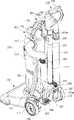
图1是根据本发明第一典型实施例的、在直立模式下操作的真空吸尘器的侧视图;1 is a side view of a vacuum cleaner operating in an upright mode according to a first exemplary embodiment of the present invention;
图2是图解示出根据本发明第一典型实施例的、处于分离状态的真空吸尘器的立体图;2 is a perspective view illustrating a vacuum cleaner in a detached state according to a first exemplary embodiment of the present invention;
图3是根据本发明第一典型实施例的、在罐式模式下操作的真空吸尘器的侧视图;Fig. 3 is a side view of a vacuum cleaner operating in a canister mode according to a first exemplary embodiment of the present invention;
图4和5是图解示出根据本发明第二典型实施例的、在直立模式下操作的真空吸尘器的立体图;4 and 5 are perspective views diagrammatically showing a vacuum cleaner operating in an upright mode according to a second exemplary embodiment of the present invention;
图6是图4所示的操作手柄组件的立体图;Fig. 6 is a perspective view of the operating handle assembly shown in Fig. 4;
图7是图4所示的携带手柄组件的立体图;Fig. 7 is a perspective view of the carrying handle assembly shown in Fig. 4;
图8是图解示出图7所示的安装在操作手柄组件内部的操作单元的立体图;8 is a perspective view diagrammatically showing the operating unit installed inside the operating handle assembly shown in FIG. 7;
图9是图解示出图8所示的连接有滑杆的操作单元的立体图;9 is a perspective view diagrammatically showing the operation unit shown in FIG. 8 to which the slide bar is connected;
图10是图解示出图8所示的操作单元的内部的横截面图;FIG. 10 is a cross-sectional view diagrammatically showing the inside of the operation unit shown in FIG. 8;
图11是根据本发明第二典型实施例的、在直立模式下操作的真空吸尘器的视图;11 is a view of a vacuum cleaner operating in an upright mode according to a second exemplary embodiment of the present invention;
图12是根据本发明第二典型实施例的、在罐式模式下操作的真空吸尘器的视图;12 is a view of a vacuum cleaner operating in a canister mode according to a second exemplary embodiment of the present invention;
所有附图中,相同的参考符号将被理解为表示相同的元件,特征和结构。Throughout the drawings, the same reference symbols will be understood to represent the same elements, features and structures.
具体实施方式Detailed ways
在说明书中限定的诸如详细结构和元件的内容为帮助全面理解本发明实施例而提供。因此,本领域技术人员可以理解,在不背离本发明的范围和精神的情况下可以对此实施例进行变更。同样,为了清楚和简明,将忽略对已知功能和结构的描述。Matters such as detailed structures and elements defined in the description are provided to assist in a comprehensive understanding of the embodiments of the present invention. Accordingly, those skilled in the art will appreciate that changes may be made in this embodiment without departing from the scope and spirit of the invention. Also, descriptions of well-known functions and constructions are omitted for clarity and conciseness.
参考图1和2,根据本发明第一典型实施例的真空吸尘器,其包括清洁单元10和吸入口组件20。清洁单元10可从吸入口组件20分离,并分离地使用。Referring to FIGS. 1 and 2 , a vacuum cleaner according to a first exemplary embodiment of the present invention includes a
清洁单元10可包括吸尘器主体11,软管13,操作手柄组件15,以及延伸管17。The
吸尘器单元11可包括吸入电机12a,吸入电机12a用于在吸尘器主体11内部产生吸力;以及灰尘分离单元12b,灰尘分离单元12b用于通过吸入电机12a产生的吸力,从通过软管13吸入的空气中分离灰尘,并收集分离的灰尘。灰尘分离单元12b可适当地具有气旋结构,用于利用离心力将灰尘从吸入的空气中分离。然而,可以理解的是也可以采用其他替代方式。例如,可安装灰尘袋以收集灰尘。The
吸尘器主体11可包括一对锁扣接合部件14a,14b,锁扣接合部件14a,14b在吸尘器主体11的一侧上竖直地对齐,用于与延伸管17锁扣接合。这里,并不限制锁扣接合部件的数目,但是可根据需要改变。例如,三个或更多锁扣接合部件,或者甚至单独一个锁扣接合部件都可形成于吸尘器主体11上,以支持吸尘器主体11和延伸管17的牢固接合。The
吸尘器主体11还可包括形成于上侧上的携带手柄11a,用于从吸入口组件20分离吸尘器主体11时,可由用户夹持,并携带吸尘器主体11。吸尘器主体11包括形成在下表面上的多个辅助轮19,用以帮助吸尘器主体11更平滑地沿地板移动。The
软管13可由柔性材料制造。软管13的一端可连接至吸尘器主体11的一侧,且软管13与灰尘分离单元12b流体连通。The
操作手柄组件15包括紧握部件15a,以被用户紧握。操作手柄组件15排列在软管13和延伸管17之间,以与两者流体连通。The operating
延伸管17扮演引导通道的角色,该引导通道将来自吸入口组件20或附件喷嘴30(图3)的灰尘引向清洁单元10。延伸管17可具有伸缩结构,从而当真空吸尘器在罐式模式下操作时,可调节长度以供使用。延伸管17可和吸尘器主体11至少一样长,以使用户能够在直立模式下来回轻松地按压吸入口组件20。The
吸入口组件20可具有形成在下表面上的吸入端口20a,吸入端口20a吸入来自待清洁表面的空气和灰尘;一对主轮21a,21b,主轮21a,21b辅助吸入口组件20沿待清洁表面的运动;以及位于后侧中间的铰接部件23。The
铰接部件23包括铰接轴23a,铰接轴23a相对于铰接部件23的前进方向以垂直关系设置,并具有与吸入口组件20可转地接合的两端;以及与铰接轴23a相接合的连接管23b。连接管23b与延伸管17可分离地连接,并在大约为90°的旋转角度(θ)内旋转。The
接管23b的旋转角度(θ)被设定为:在连接管23b处于与吸入口组件20所位于的表面成平行关系时,允许接管23b在吸入口组件20前以大约110°旋转。于是,吸尘器主体11在直立模式下相对于与地板垂直的线略微倾斜,使得吸尘器主体11的重心从吸入口组件20的后部切换至前部,因此允许吸尘器主体11牢固放置于吸入口组件20的上侧。当真空吸尘器不进行清洁操作时,这种结构防止吸尘器主体11在地板上转动,以及防止吸尘器主体11被诸如施加到吸尘器上的振动的外力影响损坏。还可采用在吸尘器主体11的下端和吸入口组件20的上端上设置的用于锁扣接合的锁扣部件的实例,用于在适当位置固定吸尘器主体11。The angle of rotation (θ) of the
连接管23b与形成于吸入口组件20内部的流入通道20b流体连通。因此连接管23b起到引导通道的作用,该引导通道将来自吸入通道20b的灰尘和空气导向延伸管17。当真空吸尘器处于直立模式时,吸尘器主体11和延伸管17可以以预定角度向用户倾斜,以允许用户更方便地使用吸尘器。The
以下将详细描述根据本发明第一典型实施例的、处于直立模式和罐式模式下的真空吸尘器操作。Operations of the vacuum cleaner in the upright mode and the canister mode according to the first exemplary embodiment of the present invention will be described in detail below.
图2主要示出处于直立模式的真空吸尘器,其中,延伸管17与锁扣一接合部件14a,14b锁扣接合,并且延伸管17的一端与铰接部件23的连接管23b相接合。FIG. 2 mainly shows the vacuum cleaner in the upright mode, wherein the
在直立模式下,清洁单元10设置在吸入口组件的上部中,通过延伸管17与吸入口组件20流体连通。In the upright mode, the
由于为电机12a供电并且电机12a产生吸力,来自待清洁表面的室内灰尘和空气通过吸入口20,然后通过吸入通道20b被吸入。As the
带有灰尘的空气在流入到灰尘分离单元12b中之前,依次通过连接管23b,延伸管17,操作手柄15以及软管13。灰尘在灰尘分离单元12b内部与空气分离,并被收集到设在灰尘分离单元12内部的灰尘收集区域(未示出)中。清洁后的空气穿过电机12a,并通过形成于吸尘器主体11的区域上的排放孔(未示出)排放至外部,该吸尘器主体11与电机12a相邻。The dust-laden air passes through the
用户可将吸尘器切换成在罐式模式下操作,以清洁某些对于相对较大和较重的立式吸尘器来说难以覆盖的地方。Users can switch the vacuum cleaner to operate in canister mode to clean certain spots that are difficult for relatively large and heavy upright vacuum cleaners.
因此,如图2所示,用户使延伸管17从铰接部件23的连接管23b分离,并因此使清洁单元10从吸入口组件20完全分离。如图3所示,然后用户使延伸管17从吸尘器主体11的锁扣-接合部件14a,14b分离,然后,需要时,将比吸入口组件20相对较小且较轻的附件喷嘴30连接至延伸管17的一端。Therefore, as shown in FIG. 2 , the user detaches the
切换成罐式吸尘器的真空吸尘器开始通过附件喷嘴30利用吸力从吸入口组件20周围吸入空气和灰尘,随着为吸入电机12a供电而开始驱动时产生该吸力。The vacuum cleaner switched to a canister cleaner starts to suck in air and dust from around the
带有灰尘的空气进入附件喷嘴30,并依次通过延伸管17,操作手柄组件15,以及软管13,并进入灰尘从空气中分离的灰尘分离单元12b。然后,灰尘在设置在灰尘分离单元12b内部的灰尘收集区域(未示出)中被收集,并且净化的空气通过吸入电机12a,并然后通过形成于部分的吸尘器主体11中的排放孔(未示出)排放至外部,该吸尘器主体11与吸入电机12a相邻The dust-laden air enters the
如上所述,由于延伸管17可在直立模式下作为框架使用,避免了用于支撑位于吸入口组件20之上的吸尘器主体11的分离框架的需要,因此吸入口组件20可以更简单设计制造,As mentioned above, since the
由于吸尘器主体11被制成在直立模式下以预定角度(θ)围绕吸入口组件20旋转,从而允许用户更方便操作吸入口组件20,因此使真空吸尘器更加便于使用。Since the cleaner
根据本发明典型实施例的真空吸尘器还通过简单的两个步骤操作易于在立式和罐式模式之间变换,该两个步骤的操作包括将延伸管17接合至连接管23b或从连接管23b分离,以及将吸尘器主体11接合至吸入口组件20或从吸入口组件20分离。Vacuum cleaners according to exemplary embodiments of the present invention are also easy to change between upright and canister modes by a simple two-step operation comprising engaging the
以下将参照图4至12说明根据本发明第二典型实施例的真空吸尘器。A vacuum cleaner according to a second exemplary embodiment of the present invention will be described below with reference to FIGS. 4 to 12 .
参照图4至12,根据本发明第二典型实施例的真空吸尘器包括吸入口组件100,吸尘器主体200,操作手柄组件300,延伸管320以及携带手柄组件400。Referring to FIGS. 4 to 12 , a vacuum cleaner according to a second exemplary embodiment of the present invention includes a
吸入口组件100可具有形成于下表面的吸入口(未示出),所述吸入口用于吸入来自待清洁表面的空气和灰尘;以及一对主轮111和112,所述一对主轮111和112用于辅助吸入口组件100在清洁表面上的运动。The
吸入口组件100还包括可关于吸入口组件100的后部中间部分转动、以允许吸尘器主体200围绕吸入口组件100转动的支撑部件120。支撑部件120可包括锁定设备(未示出),用于锁定和解锁吸尘器主体200的下端。支撑部件120还可包括延伸管容纳部件121,延伸管容纳部件121与吸入口组件100流体连通,并具有用于容纳延伸管320一端的穿孔121。The
吸入口组件100可包括用于解锁支撑部件120的第一杆,从而当吸入口组件100被改变成可运动状态时,支撑部件120固定在吸入口组件100中;以及第二杆140,第二杆140用于操作支撑部件120的锁定设备以从支撑部件120解锁吸尘器主体200的下部。The
吸尘器主体200可包括形成于前部的电机室220,电机室220用于容纳灰尘分离单元210和吸入电机(未示出);和用于可拆卸地安装延伸管320的第一和第二延伸管支撑部件241和243,以及用于可拆卸地安装软管310的第一和第二软管支撑部件245和247。第一延伸管支撑部件241以及第一和第二软管支撑部件245和247中的每个都具有打开的拱形端,以便于延伸管320或软管310的安装和拆卸,并在合适的位置中弹性地支撑延伸管320或软管310。第二延伸管支撑部件具有钩结构,并设置在吸尘器主体200的预定位置以与穿孔121a相对应,以允许用户将延伸管320插入到延伸管容纳部件121的穿孔121a中。The cleaner
吸尘器主体200还可在其两个下侧上包括一对可旋转接合的辅助轮201和203。辅助轮201和203用于当吸尘器主体200从吸入口组件100分离且在罐式模式(图12)下使用时,辅助吸尘器主体200的运动,。The
灰尘分离单元210可包括气旋单元211,气旋单元211用于通过软管310、利用离心力,将灰尘从通过管310吸入的空气中分离开;以及灰尘容器213,灰尘容器213被挤压到气旋单元211的下侧中、用于容纳从气旋单元211分离的灰尘。The
电机室220容纳用于提供内部吸力的吸入电机(未示出),并与气旋单元211流体连通,以在灰尘从气旋单元211分离后,吸入来自气旋单元211的空气。The
操作手柄组件300的一端连接至软管310,另一端连接至延伸管320。参照图6,操作手柄组件300包括形成于前面的突出301,用于插入到形成于携带手柄组件400内部的孔414c(图7)中。突出301包括形成用于容纳插销434f的锁定孔303(图7)。One end of the
操作手柄组件300还包括形成在后侧上的紧握部件305,用于被用户紧握;和一对形成在下侧上的突出307和309,用于被插入到一对引导孔414e和414f(图7)中,这将在以下进行描述。The operating
操作手柄组件300允许用户在直立模式下有效地操作真空吸尘器,并且还允许用户在罐式模式下操作与延伸管320一起形成于延伸管320的另一侧的附件喷嘴(图12)。为了打开或关闭吸入电机(未示出),按钮部件(未示出)可被设置到操作手柄组件300。The operating
延伸管320可被实现为套管,和第一典型实施例中的延伸管17相同,其长度可被调整。The
参照图7至9,携带手柄组件400可包括主体部件410,滑杆420,以及操作单元430。Referring to FIGS. 7 to 9 , the carrying
主体部件410包括前和后壳体411和413,并还包括其中限定的、用以容纳操作单元430的空间。前壳体411包括:弯曲手柄412,弯曲手柄412从用户手柄上侧向下延伸;一对引导部件414a和414b,一对引导部件414a和414b从两侧后部以预定距离相互平行突出;凹入部件414c,凹入部件414c形成在一对引导部件414a和414b之间;以及引导孔414d,引导孔414d水平地形成在凹入部件414c中。The
该对引导部件414a和414b包括一对引导槽414e和414f,用于容纳操作手柄组件300的突出对307和309,使得操作手柄组件300的突出301可精确插入到凹入部件414c中。当操作手柄组件300的突出301插入到凹入部件414c中或从凹入部件414c分离时,引导孔414d引导插销434f的横向运动,以被插入到锁定孔303中或从锁定孔303中分离。The pair of
滑杆420与沿吸尘器主体200纵向形成的杆插入部件207可滑动地接合。滑杆420包括:形成在下侧上不平区域421,用以在滑杆420被收回时,防止滑杆420与杆插入部件207完全分离。The sliding
参照图8和9,操作单元430包括杆固定壳体431,旋转单元433、按钮部件435以及弹性构件439(图10)。8 and 9, the
杆固定壳体431固定于主体部件410的内侧,并与滑杆420的上端牢固接合。杆固定壳体431包括形成于上部上的圆柱形部件432a。圆柱形部件432a引导旋转部件433的旋转,并引导按钮部件435的竖直或垂直滑动运动。圆柱形部件432a包括在其圆周上对称地形成的一对滑动突出432b和432c。The
旋转部件433包括一对沿其圆周形成的第一长孔434b和434c,以容纳第一滑动突出对432b和432c。The rotating
旋转部件433包括在其圆周上沿长度方向延伸的一对第二对称长孔434d和434e。旋转部件433包括从其圆周突出的插销434f,以及形成于插销434f一侧的倾斜面434g和434h,操作手柄组件300的突出301沿倾斜面434g和434h滑动。The rotating
按钮部件435基本以圆柱形形状形成。按钮部件435的下部依次插入旋转部件433和圆柱形部件432a,并且上部穿过主体部件410的上部而穿到主体部件410外部。按钮部件435包括从上部延伸的旋转杆436a,以旋转按钮部件435。按钮部件435包括法兰型制动器436b,以将按钮部件435的推进运动限制到预定深度。一对第二对称滑动突出436d和436e形成于制动器436b的下部的按钮部件435的圆周上,用以可滑动地插入到旋转部件433的一对第二长孔434d和434e中。The
按钮部件435包括形成于其内侧的向下逐渐变细的按压肋435c。向下逐渐变细的按压肋435c推动压杆437,压杆437穿透杆固定壳体431的上部,并且在滑杆420内侧纵向设置,使得压杆437被完全容纳在杆插入部件207时,其可使在滑杆420附近形成的锁定设备(未示出)锁定滑杆420,或使滑杆420解锁。可以应用多个锁定设备,锁定设备包括将延长手柄固定于行李上的锁定器。The
弹性构件439弹性支持按钮部件435,使得按钮部件可相对于杆固定壳体431扭转和压缩。弹性构件439的一端439a可适当地固定于杆固定壳体431的一部分,另一端439b可按需要固定于按钮部件435的向下变细的按压肋435c的一部分。可适当地使用螺旋弹簧作为弹性构件439。The
以下将描述根据本发明第二典型实施例的真空吸尘器处于罐式模式和直立模式下的操作。Operations of a vacuum cleaner in a canister mode and an upright mode according to a second exemplary embodiment of the present invention will be described below.
参照图11,当真空吸尘器在直立模式操作下时,吸尘器主体200的下部锁定在支撑部件120(图1)中。延伸管320的一端穿过第二延伸管支撑部件243(图2),并且操作手柄组件300插入操作手柄组件400的后壳体413中。Referring to FIG. 11 , when the vacuum cleaner is operated in the upright mode, the lower portion of the
该插入包括将操作手柄组件300的突出对307和309插入到引导孔对414e和414f中,和使将操作手柄组件300的突出301压住插销434f的倾斜表面434g和434h,插销434f突出通过后壳体413的引导孔414d,并被定位于后壳体413的孔414c中。The insertion includes inserting the pair of protrusions 307 and 309 of the
通过弹性件439被横向弹性支撑的插销434f以预定角度沿引导孔414d转动,且然后,当突出301插入到孔414c中时,沿引导孔414d回转,以被插入突出301的锁定孔303中。The
根据操作手柄组件300插入携带手柄组件400中的运动,延伸管320的一端插入延伸管容纳部件121的穿孔121a中。According to the motion of inserting the
然后,如图11所示,用户将操作手柄组件300举至其身高处,以使真空吸尘器沿地板方便地移动。以下将描述改变操作手柄组件300的高度的过程。Then, as shown in FIG. 11 , the user lifts the
用户拉操作手柄组件300,以使延伸管320延伸。也就是说,用户沿按钮部件435的轴向竖直地按压按钮部件435,以操作锁定设备(未示出)释放滑杆420。The user pulls on the
用户保持按压通过弹性构件439弹性支撑的按钮部件435,并拉操作手柄组件300,使得操作手柄组件300与携带手柄组件400一起,从吸尘器主体200上部被释放,其中携带手柄组件400与操作手柄组件300相接合。然后,当用户停止按压按钮部件435时,按钮部件435通过弹性构件439的返回力作用返回至原始位置。The user keeps pressing the
结果,用户可以将真空吸尘器的操作手柄组件300举至身高处,并可将真空吸尘器作为立式真空吸尘器使用。As a result, the user can lift the
以下将参照图12描述真空吸尘器从直立模式切换至罐式模式的过程。The process of switching the vacuum cleaner from the upright mode to the canister mode will be described below with reference to FIG. 12 .
当用户以预定角度转动按钮部件435的旋转杆436a时,使旋转部件435的插销434f沿引导孔414d转动,并从锁定孔303分离。When the user rotates the
用户使旋转杆436a保持在旋转位置中,并向上手拉操作手柄组件300,使得突出对307和309从引导孔对414e和414f中分离。在此过程中,当操作手柄组件300的突出301从414c分离时,插销434f沿引导孔414d运动,并返回至初始位置。The user holds the
如上所述,用户可通过简单地旋转按钮部件435和拉或推操作手柄组件300将真空吸尘器从直立模式切换至罐式模式。As described above, the user can switch the vacuum cleaner from the upright mode to the canister mode by simply rotating the
为收起真空吸尘器,参照图12,用户将操作手柄组件300锁定至携带手柄组件400,将延伸管320插入到延伸管支撑部件241和243中,将软管310插入到第一和第二管支撑部件245和247中,并推操作手柄组件300,以减小延伸管320的长度,并随后减小真空吸尘器的总体重量。To put away the vacuum cleaner, referring to FIG. 12, the user locks the operating
如在第一典型实施例中一样,由于吸入口组件100不需要用于支持吸尘器主体200的分离框架部件,因此可以实现简单的结构。As in the first exemplary embodiment, since the
根据本发明的第二典型实施例,处于直立模式下的真空吸尘器具有和第一典型实施例中相同的灰尘和空气吸入路径。因此,带有灰尘的空气进入吸入口组件100,依次穿过延伸管320,操作手柄组件300以及管310,并进入气旋单元211。灰尘被分离,并被收集在灰尘容器213中,同时空气通过吸入电机(未示出)并被排放至吸尘器主体200外部。According to the second exemplary embodiment of the present invention, the vacuum cleaner in the upright mode has the same dust and air suction paths as in the first exemplary embodiment. Therefore, air with dust enters the
尽管已经示出并说明了本发明的实施例,然而本领域普通技术人员将认识到的是,在不背离本发明的原理和精神的情况下可以对此实施例进行变更,本发明的范围由权利要求及其等效形式所限定。While an embodiment of the present invention has been shown and described, those of ordinary skill in the art will recognize that changes may be made to this embodiment without departing from the principles and spirit of the invention, the scope of which is defined by defined in the claims and their equivalents.
Claims (11)
Translated fromChineseApplications Claiming Priority (4)
| Application Number | Priority Date | Filing Date | Title |
|---|---|---|---|
| KR20070077662 | 2007-08-02 | ||
| KR20070077662 | 2007-08-02 | ||
| US60/964,676 | 2007-08-14 | ||
| KR20070093884 | 2007-09-14 |
Publications (1)
| Publication Number | Publication Date |
|---|---|
| CN101357051Atrue CN101357051A (en) | 2009-02-04 |
Family
ID=40329751
Family Applications (2)
| Application Number | Title | Priority Date | Filing Date |
|---|---|---|---|
| CNA2008101103442APendingCN101357051A (en) | 2007-08-02 | 2008-06-04 | Suction Inlet Assembly for Vacuum Cleaners |
| CNA2008101255271APendingCN101357052A (en) | 2007-08-02 | 2008-06-10 | upright vacuum cleaner |
Family Applications After (1)
| Application Number | Title | Priority Date | Filing Date |
|---|---|---|---|
| CNA2008101255271APendingCN101357052A (en) | 2007-08-02 | 2008-06-10 | upright vacuum cleaner |
Country Status (1)
| Country | Link |
|---|---|
| CN (2) | CN101357051A (en) |
Cited By (49)
| Publication number | Priority date | Publication date | Assignee | Title |
|---|---|---|---|---|
| CN103945750A (en)* | 2011-10-26 | 2014-07-23 | 伊莱克斯公司 | Cleaning nozzle for a vacuum cleaner |
| US9015899B2 (en) | 2009-03-13 | 2015-04-28 | G.B.D. Corp. | Surface cleaning apparatus with different cleaning configurations |
| WO2015068046A3 (en)* | 2013-11-07 | 2015-09-24 | Techtronic Industries Co. Ltd. | Latching arrangement for vacuum cleaner |
| US9198551B2 (en) | 2013-02-28 | 2015-12-01 | Omachron Intellectual Property Inc. | Surface cleaning apparatus |
| US9226633B2 (en) | 2009-03-13 | 2016-01-05 | Omachron Intellectual Property Inc. | Surface cleaning apparatus |
| US9232877B2 (en) | 2010-03-12 | 2016-01-12 | Omachron Intellectual Property Inc. | Surface cleaning apparatus with enhanced operability |
| CN105411494A (en)* | 2015-11-26 | 2016-03-23 | 苏州德易仕清洁科技有限公司 | Steam mop handle storage device |
| US9301662B2 (en) | 2006-12-12 | 2016-04-05 | Omachron Intellectual Property Inc. | Upright vacuum cleaner |
| CN105455725A (en)* | 2014-09-26 | 2016-04-06 | Lg电子株式会社 | Vacuum cleaner |
| US9314138B2 (en) | 2013-02-28 | 2016-04-19 | Omachron Intellectual Property Inc. | Surface cleaning apparatus |
| CN105615766A (en)* | 2014-11-03 | 2016-06-01 | 康塔有限公司 | Ground cleaning equipment |
| US9364127B2 (en) | 2013-02-28 | 2016-06-14 | Omachron Intellectual Property Inc. | Surface cleaning apparatus |
| US9386895B2 (en) | 2009-03-13 | 2016-07-12 | Omachron Intellectual Property Inc. | Surface cleaning apparatus |
| US9392916B2 (en) | 2009-03-13 | 2016-07-19 | Omachron Intellectual Property Inc. | Surface cleaning apparatus |
| US9427122B2 (en) | 2009-03-13 | 2016-08-30 | Omachron Intellectual Property Inc. | Surface cleaning apparatus |
| US9451852B2 (en) | 2009-03-13 | 2016-09-27 | Omachron Intellectual Property Inc. | Surface cleaning apparatus with different cleaning configurations |
| US9456721B2 (en) | 2013-02-28 | 2016-10-04 | Omachron Intellectual Property Inc. | Surface cleaning apparatus |
| US9480373B2 (en) | 2009-03-13 | 2016-11-01 | Omachron Intellectual Property Inc. | Surface cleaning apparatus |
| CN106419734A (en)* | 2016-09-13 | 2017-02-22 | 成都聚智工业设计有限公司 | Portable dust collector |
| US9591953B2 (en) | 2009-03-13 | 2017-03-14 | Omachron Intellectual Property Inc. | Surface cleaning apparatus |
| CN106667368A (en)* | 2017-02-23 | 2017-05-17 | 江苏美的清洁电器股份有限公司 | Air flue switching mechanism for dust collector, air inlet pipe connecting structure and dust collector |
| US9693666B2 (en) | 2011-03-04 | 2017-07-04 | Omachron Intellectual Property Inc. | Compact surface cleaning apparatus |
| US9962050B2 (en) | 2016-08-29 | 2018-05-08 | Omachron Intellectual Property Inc. | Surface cleaning apparatus |
| CN108778081A (en)* | 2015-12-21 | 2018-11-09 | 伊莱克斯家用护理产品有限公司 | Multi-functional vacuum cleaner |
| US10136780B2 (en) | 2016-08-29 | 2018-11-27 | Omachron Intellectual Property Inc. | Surface cleaning apparatus |
| US10136779B2 (en) | 2016-08-29 | 2018-11-27 | Omachron Intellectual Property Inc. | Surface cleaning apparatus |
| US10292550B2 (en) | 2016-08-29 | 2019-05-21 | Omachron Intellectual Property Inc. | Surface cleaning apparatus |
| US10299649B2 (en) | 2013-02-28 | 2019-05-28 | Omachron Intellectual Property Inc. | Surface cleaning apparatus |
| US10321794B2 (en) | 2016-08-29 | 2019-06-18 | Omachron Intellectual Property Inc. | Surface cleaning apparatus |
| US10405711B2 (en) | 2016-08-29 | 2019-09-10 | Omachron Intellectual Property Inc. | Surface cleaning apparatus |
| US10413141B2 (en) | 2016-08-29 | 2019-09-17 | Omachron Intellectual Property Inc. | Surface cleaning apparatus |
| US10433689B2 (en) | 2016-08-29 | 2019-10-08 | Omachron Intellectual Property Inc. | Surface cleaning apparatus |
| US10433686B2 (en) | 2007-08-29 | 2019-10-08 | Omachron Intellectual Property Inc. | Configuration of a surface cleaning apparatus |
| US10441125B2 (en) | 2016-08-29 | 2019-10-15 | Omachron Intellectual Property Inc. | Surface cleaning apparatus |
| US10441124B2 (en) | 2016-08-29 | 2019-10-15 | Omachron Intellectual Property Inc. | Surface cleaning apparatus |
| US10548442B2 (en) | 2009-03-13 | 2020-02-04 | Omachron Intellectual Property Inc. | Portable surface cleaning apparatus |
| US10729295B2 (en) | 2016-08-29 | 2020-08-04 | Omachron Intellectual Property Inc. | Surface cleaning apparatus |
| US10765277B2 (en) | 2006-12-12 | 2020-09-08 | Omachron Intellectual Property Inc. | Configuration of a surface cleaning apparatus |
| CN112826365A (en)* | 2016-05-09 | 2021-05-25 | Lg电子株式会社 | vacuum cleaner holder |
| US11363928B2 (en) | 2016-05-09 | 2022-06-21 | Lg Electronics Inc. | Cleaner holder |
| US11478117B2 (en) | 2016-08-29 | 2022-10-25 | Omachron Intellectual Property Inc. | Surface cleaning apparatus |
| US11612288B2 (en) | 2009-03-13 | 2023-03-28 | Omachron Intellectual Property Inc. | Surface cleaning apparatus |
| US11690489B2 (en) | 2009-03-13 | 2023-07-04 | Omachron Intellectual Property Inc. | Surface cleaning apparatus with an external dirt chamber |
| CN116472978A (en)* | 2023-04-07 | 2023-07-25 | 宁波霍德智能科技有限公司 | Multifunctional pet care device |
| US11751733B2 (en) | 2007-08-29 | 2023-09-12 | Omachron Intellectual Property Inc. | Portable surface cleaning apparatus |
| US11839348B2 (en) | 2016-05-09 | 2023-12-12 | Lg Electronics Inc. | Cleaner holder |
| US12048409B2 (en) | 2007-03-11 | 2024-07-30 | Omachron Intellectual Property Inc. | Portable surface cleaning apparatus |
| US12220099B2 (en) | 2006-12-12 | 2025-02-11 | Omachron Intellectual Property Inc. | Surface cleaning apparatus |
| US12251716B2 (en) | 2016-12-27 | 2025-03-18 | Omachron Intellectual Property Inc. | Surface cleaning apparatus |
Families Citing this family (7)
| Publication number | Priority date | Publication date | Assignee | Title |
|---|---|---|---|---|
| KR20110102606A (en)* | 2010-03-11 | 2011-09-19 | 주식회사 한경희생활과학 | Vacuum cleaner |
| GB2484122A (en)* | 2010-09-30 | 2012-04-04 | Dyson Technology Ltd | A cylinder type cleaning appliance |
| EP3030125B1 (en)* | 2013-08-09 | 2020-07-22 | Techtronic Floor Care Technology Limited | Vacuum cleaner including a removable handle assembly |
| GB2546543B (en)* | 2016-01-22 | 2019-01-02 | Dyson Technology Ltd | Separating apparatus and vacuum cleaner |
| GB2546542B (en)* | 2016-01-22 | 2018-07-04 | Dyson Technology Ltd | Vacuum cleaner |
| CN114305203B (en)* | 2020-01-03 | 2023-06-30 | 北京石头世纪科技股份有限公司 | Dust collector control method and dust collector |
| CN111973764A (en)* | 2020-08-13 | 2020-11-24 | 班涵昱 | A eliminate and kill device for clearing up object surface germ |
- 2008
- 2008-06-04CNCNA2008101103442Apatent/CN101357051A/enactivePending
- 2008-06-10CNCNA2008101255271Apatent/CN101357052A/enactivePending
Cited By (92)
| Publication number | Priority date | Publication date | Assignee | Title |
|---|---|---|---|---|
| US11700984B2 (en) | 2006-12-12 | 2023-07-18 | Omachron Intellectual Property Inc. | Configuration of a surface cleaning apparatus |
| US12256882B2 (en) | 2006-12-12 | 2025-03-25 | Omachron Intellectual Property Inc. | Upright vacuum cleaner |
| US10765277B2 (en) | 2006-12-12 | 2020-09-08 | Omachron Intellectual Property Inc. | Configuration of a surface cleaning apparatus |
| US11076729B2 (en) | 2006-12-12 | 2021-08-03 | Omachron Intellectual Property Inc. | Upright vacuum cleaner |
| US9301662B2 (en) | 2006-12-12 | 2016-04-05 | Omachron Intellectual Property Inc. | Upright vacuum cleaner |
| US12220099B2 (en) | 2006-12-12 | 2025-02-11 | Omachron Intellectual Property Inc. | Surface cleaning apparatus |
| US10076217B2 (en) | 2006-12-12 | 2018-09-18 | Omachron Intellectual Property Inc. | Upright vacuum cleaner |
| US12048409B2 (en) | 2007-03-11 | 2024-07-30 | Omachron Intellectual Property Inc. | Portable surface cleaning apparatus |
| US10542856B2 (en) | 2007-08-29 | 2020-01-28 | Omachron Intellectual Property Inc. | Configuration of a surface cleaning apparatus |
| US10433686B2 (en) | 2007-08-29 | 2019-10-08 | Omachron Intellectual Property Inc. | Configuration of a surface cleaning apparatus |
| US12324557B2 (en) | 2007-08-29 | 2025-06-10 | Omachron Intellectual Property Inc. | Portable surface cleaning apparatus |
| US10561286B2 (en) | 2007-08-29 | 2020-02-18 | Omachron Intellectual Property Inc. | Configuration of a surface cleaning apparatus |
| US11751733B2 (en) | 2007-08-29 | 2023-09-12 | Omachron Intellectual Property Inc. | Portable surface cleaning apparatus |
| US11771276B2 (en) | 2009-03-13 | 2023-10-03 | Omachron Intellectual Property Inc. | Surface cleaning apparatus |
| US11896183B2 (en) | 2009-03-13 | 2024-02-13 | Omachron Intellectual Property Inc. | Surface cleaning apparatus with different cleaning configuration |
| US9392916B2 (en) | 2009-03-13 | 2016-07-19 | Omachron Intellectual Property Inc. | Surface cleaning apparatus |
| US9427122B2 (en) | 2009-03-13 | 2016-08-30 | Omachron Intellectual Property Inc. | Surface cleaning apparatus |
| US9451852B2 (en) | 2009-03-13 | 2016-09-27 | Omachron Intellectual Property Inc. | Surface cleaning apparatus with different cleaning configurations |
| US9015899B2 (en) | 2009-03-13 | 2015-04-28 | G.B.D. Corp. | Surface cleaning apparatus with different cleaning configurations |
| US9480373B2 (en) | 2009-03-13 | 2016-11-01 | Omachron Intellectual Property Inc. | Surface cleaning apparatus |
| US11771278B2 (en) | 2009-03-13 | 2023-10-03 | Omachron Intellectual Property Inc. | Surface cleaning apparatus |
| US9591953B2 (en) | 2009-03-13 | 2017-03-14 | Omachron Intellectual Property Inc. | Surface cleaning apparatus |
| US10512374B2 (en) | 2009-03-13 | 2019-12-24 | Omachron Intellectual Property Inc. | Surface cleaning apparatus with different cleaning configurations |
| US10548442B2 (en) | 2009-03-13 | 2020-02-04 | Omachron Intellectual Property Inc. | Portable surface cleaning apparatus |
| US11771277B2 (en) | 2009-03-13 | 2023-10-03 | Omachron Intellectual Property Inc. | Surface cleaning apparatus |
| US9066642B2 (en) | 2009-03-13 | 2015-06-30 | G.B.D. Corp. | Surface cleaning apparatus with different cleaning configurations |
| US9801511B2 (en) | 2009-03-13 | 2017-10-31 | Omachron Intellectual Property Inc. | Surface cleaning apparatus with different cleaning configurations |
| US9907444B2 (en) | 2009-03-13 | 2018-03-06 | Omachron Intellectual Property Inc. | Surface cleaning apparatus with different cleaning configurations |
| US9386895B2 (en) | 2009-03-13 | 2016-07-12 | Omachron Intellectual Property Inc. | Surface cleaning apparatus |
| US11744417B2 (en) | 2009-03-13 | 2023-09-05 | Omachron Intellectual Property Inc. | Surface cleaning apparatus with different cleaning configuration |
| US11950751B2 (en) | 2009-03-13 | 2024-04-09 | Omachron Intellectual Property Inc. | Surface cleaning apparatus with an external dirt chamber |
| US9301663B2 (en) | 2009-03-13 | 2016-04-05 | Omachron Intellectual Property Inc. | Surface cleaning apparatus with different cleaning configurations |
| US11690489B2 (en) | 2009-03-13 | 2023-07-04 | Omachron Intellectual Property Inc. | Surface cleaning apparatus with an external dirt chamber |
| US11622659B2 (en) | 2009-03-13 | 2023-04-11 | Omachron Intellectual Property Inc. | Portable surface cleaning apparatus |
| US11612288B2 (en) | 2009-03-13 | 2023-03-28 | Omachron Intellectual Property Inc. | Surface cleaning apparatus |
| US11571096B2 (en) | 2009-03-13 | 2023-02-07 | Omachron Intellectual Property Inc. | Surface cleaning apparatus with different cleaning configurations |
| US11529031B2 (en) | 2009-03-13 | 2022-12-20 | Omachron Intellectual Property Inc. | Portable surface cleaning apparatus |
| US10327608B2 (en) | 2009-03-13 | 2019-06-25 | Omachron Intellectual Property Inc. | Surface cleaning apparatus with different cleaning configurations |
| US11330944B2 (en) | 2009-03-13 | 2022-05-17 | Omachron Intellectual Property Inc. | Portable surface cleaning apparatus |
| US12251074B2 (en) | 2009-03-13 | 2025-03-18 | Omachron Intellectual Property Inc. | Surface cleaning apparatus with an external dirt chamber |
| US9226633B2 (en) | 2009-03-13 | 2016-01-05 | Omachron Intellectual Property Inc. | Surface cleaning apparatus |
| US9232877B2 (en) | 2010-03-12 | 2016-01-12 | Omachron Intellectual Property Inc. | Surface cleaning apparatus with enhanced operability |
| US11771275B2 (en) | 2010-03-12 | 2023-10-03 | Omachron Intellectual Property Inc. | Surface cleaning apparatus with enhanced operability |
| US9668631B2 (en) | 2010-03-12 | 2017-06-06 | Omachron Intellectual Property Inc. | Surface cleaning apparatus with enhanced operability |
| US11839342B2 (en) | 2010-03-12 | 2023-12-12 | Omachron Intellectual Property Inc. | Surface cleaning apparatus with enhanced operability |
| US9693666B2 (en) | 2011-03-04 | 2017-07-04 | Omachron Intellectual Property Inc. | Compact surface cleaning apparatus |
| US10602894B2 (en) | 2011-03-04 | 2020-03-31 | Omachron Intellectual Property Inc. | Portable surface cleaning apparatus |
| US11612283B2 (en) | 2011-03-04 | 2023-03-28 | Omachron Intellectual Property Inc. | Surface cleaning apparatus |
| CN103945750A (en)* | 2011-10-26 | 2014-07-23 | 伊莱克斯公司 | Cleaning nozzle for a vacuum cleaner |
| US10638897B2 (en) | 2013-02-28 | 2020-05-05 | Omachron Intellectual Property Inc. | Surface cleaning apparatus |
| US9364127B2 (en) | 2013-02-28 | 2016-06-14 | Omachron Intellectual Property Inc. | Surface cleaning apparatus |
| US11700985B2 (en) | 2013-02-28 | 2023-07-18 | Omachron Intellectual Property Inc. | Surface cleaning apparatus |
| US9931005B2 (en) | 2013-02-28 | 2018-04-03 | Omachron lntellectual Property Inc. | Surface cleaning apparatus |
| US10299649B2 (en) | 2013-02-28 | 2019-05-28 | Omachron Intellectual Property Inc. | Surface cleaning apparatus |
| US10893783B2 (en) | 2013-02-28 | 2021-01-19 | Omachron Intellectual Property Inc. | Surface cleaning apparatus |
| US9198551B2 (en) | 2013-02-28 | 2015-12-01 | Omachron Intellectual Property Inc. | Surface cleaning apparatus |
| US9314138B2 (en) | 2013-02-28 | 2016-04-19 | Omachron Intellectual Property Inc. | Surface cleaning apparatus |
| US9456721B2 (en) | 2013-02-28 | 2016-10-04 | Omachron Intellectual Property Inc. | Surface cleaning apparatus |
| US10624511B2 (en) | 2013-02-28 | 2020-04-21 | Omachron Intellectual Property Inc. | Surface cleaning apparatus |
| US11889968B2 (en) | 2013-02-28 | 2024-02-06 | Omachron Intellectual Property Inc. | Surface cleaning apparatus |
| EP3065612A4 (en)* | 2013-11-07 | 2017-08-02 | Techtronic Industries Company Limited | Latching arrangement for vacuum cleaner |
| WO2015068046A3 (en)* | 2013-11-07 | 2015-09-24 | Techtronic Industries Co. Ltd. | Latching arrangement for vacuum cleaner |
| CN105455725A (en)* | 2014-09-26 | 2016-04-06 | Lg电子株式会社 | Vacuum cleaner |
| US10413142B2 (en) | 2014-09-26 | 2019-09-17 | Lg Electronics Inc. | Vacuum cleaner |
| CN105615766A (en)* | 2014-11-03 | 2016-06-01 | 康塔有限公司 | Ground cleaning equipment |
| CN105411494A (en)* | 2015-11-26 | 2016-03-23 | 苏州德易仕清洁科技有限公司 | Steam mop handle storage device |
| CN108778081A (en)* | 2015-12-21 | 2018-11-09 | 伊莱克斯家用护理产品有限公司 | Multi-functional vacuum cleaner |
| CN108778081B (en)* | 2015-12-21 | 2023-06-02 | 伊莱克斯家用护理产品有限公司 | multifunctional vacuum cleaner |
| US11839348B2 (en) | 2016-05-09 | 2023-12-12 | Lg Electronics Inc. | Cleaner holder |
| CN112826365A (en)* | 2016-05-09 | 2021-05-25 | Lg电子株式会社 | vacuum cleaner holder |
| US12150614B2 (en) | 2016-05-09 | 2024-11-26 | Lg Electronics Inc. | Cleaner holder |
| US12108923B2 (en) | 2016-05-09 | 2024-10-08 | Lg Electronics Inc. | Cleaner holder |
| US11363928B2 (en) | 2016-05-09 | 2022-06-21 | Lg Electronics Inc. | Cleaner holder |
| US11399676B2 (en) | 2016-05-09 | 2022-08-02 | Lg Electronics Inc. | Cleaner holder |
| US10292550B2 (en) | 2016-08-29 | 2019-05-21 | Omachron Intellectual Property Inc. | Surface cleaning apparatus |
| US10413141B2 (en) | 2016-08-29 | 2019-09-17 | Omachron Intellectual Property Inc. | Surface cleaning apparatus |
| US10441125B2 (en) | 2016-08-29 | 2019-10-15 | Omachron Intellectual Property Inc. | Surface cleaning apparatus |
| US10433689B2 (en) | 2016-08-29 | 2019-10-08 | Omachron Intellectual Property Inc. | Surface cleaning apparatus |
| US10729295B2 (en) | 2016-08-29 | 2020-08-04 | Omachron Intellectual Property Inc. | Surface cleaning apparatus |
| US11478117B2 (en) | 2016-08-29 | 2022-10-25 | Omachron Intellectual Property Inc. | Surface cleaning apparatus |
| US10136780B2 (en) | 2016-08-29 | 2018-11-27 | Omachron Intellectual Property Inc. | Surface cleaning apparatus |
| US10136779B2 (en) | 2016-08-29 | 2018-11-27 | Omachron Intellectual Property Inc. | Surface cleaning apparatus |
| US10405711B2 (en) | 2016-08-29 | 2019-09-10 | Omachron Intellectual Property Inc. | Surface cleaning apparatus |
| US10321794B2 (en) | 2016-08-29 | 2019-06-18 | Omachron Intellectual Property Inc. | Surface cleaning apparatus |
| US9962050B2 (en) | 2016-08-29 | 2018-05-08 | Omachron Intellectual Property Inc. | Surface cleaning apparatus |
| US10441124B2 (en) | 2016-08-29 | 2019-10-15 | Omachron Intellectual Property Inc. | Surface cleaning apparatus |
| US12161281B2 (en) | 2016-08-29 | 2024-12-10 | Omachron Intellectual Property Inc. | Surface cleaning apparatus |
| CN106419734A (en)* | 2016-09-13 | 2017-02-22 | 成都聚智工业设计有限公司 | Portable dust collector |
| US12251716B2 (en) | 2016-12-27 | 2025-03-18 | Omachron Intellectual Property Inc. | Surface cleaning apparatus |
| CN106667368A (en)* | 2017-02-23 | 2017-05-17 | 江苏美的清洁电器股份有限公司 | Air flue switching mechanism for dust collector, air inlet pipe connecting structure and dust collector |
| CN116472978A (en)* | 2023-04-07 | 2023-07-25 | 宁波霍德智能科技有限公司 | Multifunctional pet care device |
| CN116472978B (en)* | 2023-04-07 | 2023-10-03 | 宁波霍德智能科技有限公司 | Multifunctional pet care device |
Also Published As
| Publication number | Publication date |
|---|---|
| CN101357052A (en) | 2009-02-04 |
Similar Documents
| Publication | Publication Date | Title |
|---|---|---|
| CN101357051A (en) | Suction Inlet Assembly for Vacuum Cleaners | |
| US20090031522A1 (en) | Suction port assembly of vacuum cleaner | |
| KR100831346B1 (en) | Vacuum cleaner | |
| KR101491002B1 (en) | Vacuum cleaner | |
| US20090144929A1 (en) | Vacuum cleaner used as both upright type cleaner and canister type cleaner | |
| CA2659212C (en) | Surface cleaning apparatus | |
| CN101390723B (en) | A cleaning device | |
| JP4692590B2 (en) | Vacuum cleaner handle assembly | |
| US20100175217A1 (en) | Cyclonic surface cleaning apparatus with externally positioned dirt chamber | |
| KR20080096191A (en) | Canister / Stick Vacuum Cleaner | |
| US20070251048A1 (en) | Vacuum cleaner | |
| US20100229334A1 (en) | Dirt collection chamber for a cyclonic surface cleaning apparatus | |
| CN108135413A (en) | Cyclone dust collector and with its vacuum cleaner | |
| US7155772B2 (en) | Fixing device for attaching/detaching dust receptacle of cyclone-type vacuum cleaner and vacuum cleaner having the same | |
| US20060225243A1 (en) | Vacuum cleaner | |
| JP7461729B2 (en) | Vacuum cleaner | |
| KR20090013644A (en) | Vacuum cleaner with upright and canister type | |
| KR100934135B1 (en) | Vacuum cleaner | |
| JP4559920B2 (en) | Vacuum cleaner | |
| KR101043840B1 (en) | Vacuum cleaner | |
| KR100941426B1 (en) | Dust collection unit of vacuum cleaner | |
| CN221331056U (en) | Surface cleaning equipment | |
| CN120641013A (en) | Multipurpose vacuum cleaner |
Legal Events
| Date | Code | Title | Description |
|---|---|---|---|
| C06 | Publication | ||
| PB01 | Publication | ||
| C10 | Entry into substantive examination | ||
| SE01 | Entry into force of request for substantive examination | ||
| C02 | Deemed withdrawal of patent application after publication (patent law 2001) | ||
| WD01 | Invention patent application deemed withdrawn after publication | Application publication date:20090204 |