CN101355975B - Medical Fluid Injection System - Google Patents
Medical Fluid Injection SystemDownload PDFInfo
- Publication number
- CN101355975B CN101355975BCN2006800508258ACN200680050825ACN101355975BCN 101355975 BCN101355975 BCN 101355975BCN 2006800508258 ACN2006800508258 ACN 2006800508258ACN 200680050825 ACN200680050825 ACN 200680050825ACN 101355975 BCN101355975 BCN 101355975B
- Authority
- CN
- China
- Prior art keywords
- injection
- syringe
- display
- user
- patient
- Prior art date
- Legal status (The legal status is an assumption and is not a legal conclusion. Google has not performed a legal analysis and makes no representation as to the accuracy of the status listed.)
- Active
Links
Images


Classifications
- A—HUMAN NECESSITIES
- A61—MEDICAL OR VETERINARY SCIENCE; HYGIENE
- A61M—DEVICES FOR INTRODUCING MEDIA INTO, OR ONTO, THE BODY; DEVICES FOR TRANSDUCING BODY MEDIA OR FOR TAKING MEDIA FROM THE BODY; DEVICES FOR PRODUCING OR ENDING SLEEP OR STUPOR
- A61M5/00—Devices for bringing media into the body in a subcutaneous, intra-vascular or intramuscular way; Accessories therefor, e.g. filling or cleaning devices, arm-rests
- A61M5/007—Devices for bringing media into the body in a subcutaneous, intra-vascular or intramuscular way; Accessories therefor, e.g. filling or cleaning devices, arm-rests for contrast media
- A—HUMAN NECESSITIES
- A61—MEDICAL OR VETERINARY SCIENCE; HYGIENE
- A61M—DEVICES FOR INTRODUCING MEDIA INTO, OR ONTO, THE BODY; DEVICES FOR TRANSDUCING BODY MEDIA OR FOR TAKING MEDIA FROM THE BODY; DEVICES FOR PRODUCING OR ENDING SLEEP OR STUPOR
- A61M5/00—Devices for bringing media into the body in a subcutaneous, intra-vascular or intramuscular way; Accessories therefor, e.g. filling or cleaning devices, arm-rests
- A—HUMAN NECESSITIES
- A61—MEDICAL OR VETERINARY SCIENCE; HYGIENE
- A61M—DEVICES FOR INTRODUCING MEDIA INTO, OR ONTO, THE BODY; DEVICES FOR TRANSDUCING BODY MEDIA OR FOR TAKING MEDIA FROM THE BODY; DEVICES FOR PRODUCING OR ENDING SLEEP OR STUPOR
- A61M31/00—Devices for introducing or retaining media, e.g. remedies, in cavities of the body
- A—HUMAN NECESSITIES
- A61—MEDICAL OR VETERINARY SCIENCE; HYGIENE
- A61M—DEVICES FOR INTRODUCING MEDIA INTO, OR ONTO, THE BODY; DEVICES FOR TRANSDUCING BODY MEDIA OR FOR TAKING MEDIA FROM THE BODY; DEVICES FOR PRODUCING OR ENDING SLEEP OR STUPOR
- A61M5/00—Devices for bringing media into the body in a subcutaneous, intra-vascular or intramuscular way; Accessories therefor, e.g. filling or cleaning devices, arm-rests
- A61M5/14—Infusion devices, e.g. infusing by gravity; Blood infusion; Accessories therefor
- A61M5/142—Pressure infusion, e.g. using pumps
- A61M5/14212—Pumping with an aspiration and an expulsion action
- A61M5/14216—Reciprocating piston type
- A—HUMAN NECESSITIES
- A61—MEDICAL OR VETERINARY SCIENCE; HYGIENE
- A61M—DEVICES FOR INTRODUCING MEDIA INTO, OR ONTO, THE BODY; DEVICES FOR TRANSDUCING BODY MEDIA OR FOR TAKING MEDIA FROM THE BODY; DEVICES FOR PRODUCING OR ENDING SLEEP OR STUPOR
- A61M5/00—Devices for bringing media into the body in a subcutaneous, intra-vascular or intramuscular way; Accessories therefor, e.g. filling or cleaning devices, arm-rests
- A61M5/14—Infusion devices, e.g. infusing by gravity; Blood infusion; Accessories therefor
- A61M5/142—Pressure infusion, e.g. using pumps
- A61M5/145—Pressure infusion, e.g. using pumps using pressurised reservoirs, e.g. pressurised by means of pistons
- A61M5/1452—Pressure infusion, e.g. using pumps using pressurised reservoirs, e.g. pressurised by means of pistons pressurised by means of pistons
- A—HUMAN NECESSITIES
- A61—MEDICAL OR VETERINARY SCIENCE; HYGIENE
- A61M—DEVICES FOR INTRODUCING MEDIA INTO, OR ONTO, THE BODY; DEVICES FOR TRANSDUCING BODY MEDIA OR FOR TAKING MEDIA FROM THE BODY; DEVICES FOR PRODUCING OR ENDING SLEEP OR STUPOR
- A61M5/00—Devices for bringing media into the body in a subcutaneous, intra-vascular or intramuscular way; Accessories therefor, e.g. filling or cleaning devices, arm-rests
- A61M5/14—Infusion devices, e.g. infusing by gravity; Blood infusion; Accessories therefor
- A61M5/168—Means for controlling media flow to the body or for metering media to the body, e.g. drip meters, counters ; Monitoring media flow to the body
- A61M5/16804—Flow controllers
- A61M5/16827—Flow controllers controlling delivery of multiple fluids, e.g. sequencing, mixing or via separate flow-paths
- A—HUMAN NECESSITIES
- A61—MEDICAL OR VETERINARY SCIENCE; HYGIENE
- A61M—DEVICES FOR INTRODUCING MEDIA INTO, OR ONTO, THE BODY; DEVICES FOR TRANSDUCING BODY MEDIA OR FOR TAKING MEDIA FROM THE BODY; DEVICES FOR PRODUCING OR ENDING SLEEP OR STUPOR
- A61M5/00—Devices for bringing media into the body in a subcutaneous, intra-vascular or intramuscular way; Accessories therefor, e.g. filling or cleaning devices, arm-rests
- A61M5/14—Infusion devices, e.g. infusing by gravity; Blood infusion; Accessories therefor
- A61M5/168—Means for controlling media flow to the body or for metering media to the body, e.g. drip meters, counters ; Monitoring media flow to the body
- A61M5/16877—Adjusting flow; Devices for setting a flow rate
- A—HUMAN NECESSITIES
- A61—MEDICAL OR VETERINARY SCIENCE; HYGIENE
- A61M—DEVICES FOR INTRODUCING MEDIA INTO, OR ONTO, THE BODY; DEVICES FOR TRANSDUCING BODY MEDIA OR FOR TAKING MEDIA FROM THE BODY; DEVICES FOR PRODUCING OR ENDING SLEEP OR STUPOR
- A61M5/00—Devices for bringing media into the body in a subcutaneous, intra-vascular or intramuscular way; Accessories therefor, e.g. filling or cleaning devices, arm-rests
- A61M5/36—Devices for bringing media into the body in a subcutaneous, intra-vascular or intramuscular way; Accessories therefor, e.g. filling or cleaning devices, arm-rests with means for eliminating or preventing injection or infusion of air into body
- A61M5/365—Air detectors
- G—PHYSICS
- G16—INFORMATION AND COMMUNICATION TECHNOLOGY [ICT] SPECIALLY ADAPTED FOR SPECIFIC APPLICATION FIELDS
- G16H—HEALTHCARE INFORMATICS, i.e. INFORMATION AND COMMUNICATION TECHNOLOGY [ICT] SPECIALLY ADAPTED FOR THE HANDLING OR PROCESSING OF MEDICAL OR HEALTHCARE DATA
- G16H40/00—ICT specially adapted for the management or administration of healthcare resources or facilities; ICT specially adapted for the management or operation of medical equipment or devices
- G16H40/60—ICT specially adapted for the management or administration of healthcare resources or facilities; ICT specially adapted for the management or operation of medical equipment or devices for the operation of medical equipment or devices
- G16H40/63—ICT specially adapted for the management or administration of healthcare resources or facilities; ICT specially adapted for the management or operation of medical equipment or devices for the operation of medical equipment or devices for local operation
- G—PHYSICS
- G16—INFORMATION AND COMMUNICATION TECHNOLOGY [ICT] SPECIALLY ADAPTED FOR SPECIFIC APPLICATION FIELDS
- G16Z—INFORMATION AND COMMUNICATION TECHNOLOGY [ICT] SPECIALLY ADAPTED FOR SPECIFIC APPLICATION FIELDS, NOT OTHERWISE PROVIDED FOR
- G16Z99/00—Subject matter not provided for in other main groups of this subclass
- A—HUMAN NECESSITIES
- A61—MEDICAL OR VETERINARY SCIENCE; HYGIENE
- A61B—DIAGNOSIS; SURGERY; IDENTIFICATION
- A61B6/00—Apparatus or devices for radiation diagnosis; Apparatus or devices for radiation diagnosis combined with radiation therapy equipment
- A61B6/48—Diagnostic techniques
- A61B6/481—Diagnostic techniques involving the use of contrast agents
- A—HUMAN NECESSITIES
- A61—MEDICAL OR VETERINARY SCIENCE; HYGIENE
- A61B—DIAGNOSIS; SURGERY; IDENTIFICATION
- A61B6/00—Apparatus or devices for radiation diagnosis; Apparatus or devices for radiation diagnosis combined with radiation therapy equipment
- A61B6/50—Apparatus or devices for radiation diagnosis; Apparatus or devices for radiation diagnosis combined with radiation therapy equipment specially adapted for specific body parts; specially adapted for specific clinical applications
- A61B6/504—Apparatus or devices for radiation diagnosis; Apparatus or devices for radiation diagnosis combined with radiation therapy equipment specially adapted for specific body parts; specially adapted for specific clinical applications for diagnosis of blood vessels, e.g. by angiography
- A—HUMAN NECESSITIES
- A61—MEDICAL OR VETERINARY SCIENCE; HYGIENE
- A61B—DIAGNOSIS; SURGERY; IDENTIFICATION
- A61B6/00—Apparatus or devices for radiation diagnosis; Apparatus or devices for radiation diagnosis combined with radiation therapy equipment
- A61B6/54—Control of apparatus or devices for radiation diagnosis
- A61B6/548—Remote control of the apparatus or devices
- A—HUMAN NECESSITIES
- A61—MEDICAL OR VETERINARY SCIENCE; HYGIENE
- A61M—DEVICES FOR INTRODUCING MEDIA INTO, OR ONTO, THE BODY; DEVICES FOR TRANSDUCING BODY MEDIA OR FOR TAKING MEDIA FROM THE BODY; DEVICES FOR PRODUCING OR ENDING SLEEP OR STUPOR
- A61M5/00—Devices for bringing media into the body in a subcutaneous, intra-vascular or intramuscular way; Accessories therefor, e.g. filling or cleaning devices, arm-rests
- A61M5/14—Infusion devices, e.g. infusing by gravity; Blood infusion; Accessories therefor
- A61M2005/1401—Functional features
- A61M2005/1403—Flushing or purging
- A—HUMAN NECESSITIES
- A61—MEDICAL OR VETERINARY SCIENCE; HYGIENE
- A61M—DEVICES FOR INTRODUCING MEDIA INTO, OR ONTO, THE BODY; DEVICES FOR TRANSDUCING BODY MEDIA OR FOR TAKING MEDIA FROM THE BODY; DEVICES FOR PRODUCING OR ENDING SLEEP OR STUPOR
- A61M5/00—Devices for bringing media into the body in a subcutaneous, intra-vascular or intramuscular way; Accessories therefor, e.g. filling or cleaning devices, arm-rests
- A61M5/14—Infusion devices, e.g. infusing by gravity; Blood infusion; Accessories therefor
- A61M5/168—Means for controlling media flow to the body or for metering media to the body, e.g. drip meters, counters ; Monitoring media flow to the body
- A61M5/16804—Flow controllers
- A61M5/16809—Flow controllers by repeated filling and emptying of an intermediate volume
- A—HUMAN NECESSITIES
- A61—MEDICAL OR VETERINARY SCIENCE; HYGIENE
- A61M—DEVICES FOR INTRODUCING MEDIA INTO, OR ONTO, THE BODY; DEVICES FOR TRANSDUCING BODY MEDIA OR FOR TAKING MEDIA FROM THE BODY; DEVICES FOR PRODUCING OR ENDING SLEEP OR STUPOR
- A61M5/00—Devices for bringing media into the body in a subcutaneous, intra-vascular or intramuscular way; Accessories therefor, e.g. filling or cleaning devices, arm-rests
- A61M5/36—Devices for bringing media into the body in a subcutaneous, intra-vascular or intramuscular way; Accessories therefor, e.g. filling or cleaning devices, arm-rests with means for eliminating or preventing injection or infusion of air into body
Landscapes
- Health & Medical Sciences (AREA)
- Engineering & Computer Science (AREA)
- Biomedical Technology (AREA)
- Public Health (AREA)
- General Health & Medical Sciences (AREA)
- Heart & Thoracic Surgery (AREA)
- Hematology (AREA)
- Life Sciences & Earth Sciences (AREA)
- Animal Behavior & Ethology (AREA)
- Anesthesiology (AREA)
- Veterinary Medicine (AREA)
- Vascular Medicine (AREA)
- Business, Economics & Management (AREA)
- General Business, Economics & Management (AREA)
- Epidemiology (AREA)
- Medical Informatics (AREA)
- Primary Health Care (AREA)
- Emergency Medicine (AREA)
- Physics & Mathematics (AREA)
- Fluid Mechanics (AREA)
- Infusion, Injection, And Reservoir Apparatuses (AREA)
Abstract
Description
Translated fromChinese技术领域technical field
本发明一般涉及一种改进的注射器系统,该系统用于注射诸如射线照像造影流体的医用流体,并特别适应于血管造影术。The present invention relates generally to an improved injector system for injecting medical fluids, such as radiographic contrast fluids, and is particularly adapted for angiography.
背景技术Background technique
血管造影术是用于诊断和治疗心血管状况的进程,包括血管的反常或受限情况,血管在人体或动物体内构成使血液行进通过的通路网络。在血管造影术过程中,射线照像造影材料通过导管注射到静脉或动脉中,并且之后行进到与静脉或动脉流体连通的血管结构中。当X光通过体内造影材料被注射进入的区域时,X光被造影材料吸收,从而提供了所希望血管结构的射线照像影像。所述影像可记录在胶片或录影带上和/或显示在荧光镜监视器上。所述影像可用于多种目的,例如,诊断和例如血管成形术之类的治疗进程,其中,气球可插入血管系统中并充气以打开狭窄处。Angiography is a procedure used to diagnose and treat cardiovascular conditions, including abnormalities or restrictions of the blood vessels that form the network of pathways in the human or animal body through which blood travels. During angiography, radiographic contrast material is injected through a catheter into a vein or artery and then travels into vascular structures in fluid communication with the vein or artery. As the x-rays pass through the region of the body into which the contrast material is injected, the x-rays are absorbed by the contrast material, thereby providing a radiographic image of the desired vascular structure. The images can be recorded on film or videotape and/or displayed on a fluoroscopic monitor. The images can be used for a variety of purposes, eg, diagnostics and therapeutic procedures such as angioplasty, in which a balloon is inserted into the vascular system and inflated to open up a stenosis.
造影材料可通过手动或自动注射系统注射到导管中。虽然用于注射造影材料的设备可以不同,但大多数当前系统包括有效连接到导管的注射管。注射管具有用于保持造影材料的腔和在腔内可往复运动的柱塞。当柱塞移动而在腔内形成局部真空时,造影材料被吸入腔中。柱塞反向移动首先迫使空气排出腔外,然后以由柱塞移动速度确定的速度和量将造影材料传输到导管。Contrast material can be injected into the catheter by manual or automated injection systems. While the equipment used to inject the contrast material can vary, most current systems include an injection tube operatively connected to a catheter. The syringe has a lumen for holding the contrast material and a plunger reciprocable within the lumen. Contrast material is drawn into the lumen as the plunger moves to create a partial vacuum within the lumen. Reverse movement of the plunger first forces air out of the lumen and then delivers contrast material to the catheter at a rate and volume determined by the speed of plunger movement.
在手动系统中,用户或操作者加载注射管并在将注射管连接到导管之前将空气从腔中排出。手动系统的用户通过改变施加于柱塞的人力而调节注射的速度和量。手动系统的最大注射压力通常限制在150 p.s.i.(即,可由人的手施加的最大压力),且流体最大量约为12cc。这样的手动系统通常不适合于任何安全特性,例如,限制或防止注射超出预定注射参数(例如速度或压力)范围,并通常不包括用于探测空气气泡或其他有害物的致动传感器或警报。In manual systems, the user or operator loads the syringe and expels air from the lumen before connecting the syringe to the catheter. Users of manual systems adjust the speed and volume of injection by varying the human force applied to the plunger. Manual systems are typically limited to a maximum injection pressure of 150 p.s.i. (ie, the maximum pressure that can be applied by a human hand) and a maximum fluid volume of approximately 12cc. Such manual systems are generally not adapted for any safety features, such as limiting or preventing injections outside predetermined injection parameters (eg, speed or pressure), and generally do not include actuation sensors or alarms to detect air bubbles or other hazards.
血管造影术可以包括注射不同于造影材料的流体。例如,可能希望进行盐水冲洗和/或流体药物注射。最常用手动注射系统中的一种包括:具有多个手动致动阀的阀机构,操作者选择性地开启和关闭这些阀,以引导所希望的流体流入或流出连接到注射管或导管的流体通道。当操作者将造影材料抽吸或注射进入注射管腔中或将其排出时,流体流动通过由所述阀的相对位置引导的最小阻力路径。当改变阀的位置时,可选择性地注射一种或多种流体。Angiography may involve injection of a fluid other than the contrast material. For example, saline flushes and/or fluid drug injections may be desired. One of the most commonly used manual injection systems includes a valve mechanism with a plurality of manually actuated valves that the operator selectively opens and closes to direct the desired fluid flow into or out of a fluid connected to a syringe or catheter aisle. When the operator aspirates or injects contrast material into the injection lumen or expels it, fluid flows through the path of least resistance directed by the relative positions of the valves. When changing the position of the valve, one or more fluids can be selectively injected.
特定的自动流体传输系统提供控制面板或用户界面,其可通过例如医生的经过训练的专业人员使用或操作。专业人员可使用控制面板输入一个或多个注射参数。用户界面可包括触摸面板屏幕。这些参数可然后在病人注射进程中使用。特定的自动注射系统需要输入以下注射参数:将被注射的造影材料的量,注射流速,所允许的最大注射压力,和注射流速变化率(即,上升时间)。控制面板可直接连接到注射头或连接到病人的床台面。Certain automated fluid transfer systems provide a control panel or user interface that can be used or operated by a trained professional such as a physician. A professional may use the control panel to enter one or more injection parameters. The user interface may include a touch panel screen. These parameters can then be used during the patient injection procedure. A particular automatic injection system requires input of the following injection parameters: amount of contrast material to be injected, injection flow rate, maximum allowable injection pressure, and rate of change of injection flow rate (ie, rise time). The control panel can be attached directly to the injection head or to the patient's bedtop.
发明内容Contents of the invention
根据特定的实施例,提供一种具有双注射管组件的注射系统。一个注射管能够保持第一流体介质(例如造影剂),而第二注射管能够保持第二流体介质(例如盐水)。每一注射管包括独立的入口和出口端口。入口端口用于将注射管填充以流体,而出口端口用于将流体从注射管中排出。According to certain embodiments, an injection system having a dual syringe assembly is provided. One syringe can hold a first fluid medium (eg contrast medium) and the second syringe can hold a second fluid medium (eg saline). Each syringe includes independent inlet and outlet ports. The inlet port is used to fill the syringe with fluid, and the outlet port is used to expel fluid from the syringe.
根据特定的实施例,提供一种使用一次性盒的注射系统,一次性盒提供至注射系统的流体连接。由注射系统配发的流体通过一次性盒提供给病人。一个或多个管路部件连接在注射系统与一次性盒之间。阀,且特别是节流阀,可用于防止流体在特定情况下流到一次性盒,并且还防止流体回流。一次性盒提供在盒与注射系统之间的流体连接,并且还提供用于可连接到病人管路的连接。一次性盒可为在每次病人使用之后弃置的单一用途部件。According to certain embodiments, there is provided an injection system using a disposable cartridge providing a fluid connection to the injection system. Fluids dispensed by the injection system are provided to the patient through a disposable cartridge. One or more tubing components are connected between the injection system and the disposable cartridge. Valves, and particularly throttle valves, can be used to prevent fluid from flowing to the disposable cartridge under certain circumstances, and also to prevent fluid from flowing back. The disposable cartridge provides a fluid connection between the cartridge and the injection system, and also provides connections for connectable to patient circuits. The disposable cartridge may be a single use component that is disposed of after each patient use.
根据特定的实施例,提供一种具有多个显示装置的注射系统。在此方面,小的显示装置可直接设置在指示器上,而较大的显示装置(主控制面板)可远离小的显示装置定位。小的显示装置可用于提供设定信息、错误及解决信息、和其他系统信息,而且还可用于获取来自用户的特定输入,例如瓶或袋的尺寸。在一个方面,提供另外的远程显示器,其可为个人数字助理(PDA)的尺寸。根据一个实施例,这种另外的远程显示器可通过无线连接与主控制面板通讯。由于这种显示器可移动,因而医生可灵活使用这种另外的远程显示器。所述另外的显示器由于其尺寸而非常轻便并便于使用。在一个实施方案中,所述另外的显示器提供了用户输入能力和显示输出能力。According to certain embodiments, an infusion system having a plurality of display devices is provided. In this regard, the small display device can be positioned directly on the indicator, while the larger display device (main control panel) can be located remotely from the small display device. A small display device can be used to provide setup information, error and resolution information, and other system information, and can also be used to capture specific input from the user, such as bottle or bag dimensions. In one aspect, an additional remote display is provided, which may be the size of a personal digital assistant (PDA). According to one embodiment, such additional remote displays may communicate with the main control panel via a wireless connection. Since this display is movable, the doctor has the flexibility to use this additional remote display. The additional display is very light and easy to use due to its size. In one embodiment, the additional display provides user input capabilities and display output capabilities.
根据特定的实施例,提供一种注射系统,以实现使用情景照明辅助流体注射系统用户的方法。在这些实施例中,所述方法包括:在流体注射系统上提供第一视觉指示物以指示用户在系统上执行设定功能,如果用户不正确执行设定功能,则在系统上提供第二视觉指示物,如果用户正确执行了设定功能,则在系统上提供第三视觉指示物。According to certain embodiments, an infusion system is provided to enable a method of assisting a user of a fluid infusion system using contextual lighting. In these embodiments, the method includes providing a first visual indicator on the fluid injection system to instruct the user to perform a programmed function on the system, and providing a second visual indicator on the system if the user incorrectly performed the programmed function. An indicator, providing a third visual indicator on the system if the user has correctly performed the set function.
根据特定的实施例,提供一种注射系统,其中具有改进的图形用户界面(GUI),用于在系统中的显示装置中进行显示。一个方面还提供了可个性化区域注射按钮、用于快速浏览的图标、和预限定图标的范围。在一些实施例中,GUI在系统的指导或快速设定模式中提供用户界面。在这些实施例中,GUI的功能可与情景照明的一个或多个方面同步。GUI中的各种其他项目提供了改进的用户界面。According to certain embodiments, an injection system is provided having an improved graphical user interface (GUI) for display on a display device in the system. An aspect also provides a personalisable area injection button, icons for quick viewing, and a range of predefined icons. In some embodiments, the GUI provides a user interface in a guided or quick setup mode of the system. In these embodiments, the functionality of the GUI may be synchronized with one or more aspects of ambient lighting. Various other items in the GUI provide an improved user interface.
本发明一个或多个实施例的细节在以下的附图和描述中阐述。根据描述和附图并根据各权利要求,本发明的其他特征、目的和优点将变得显而易见。The details of one or more embodiments of the invention are set forth in the accompanying drawings and the description below. Other features, objects, and advantages of the invention will be apparent from the description and drawings, and from the claims.
附图说明Description of drawings
图1是例示血管造影注射器系统的优选实施例的立体图。Figure 1 is a perspective view illustrating a preferred embodiment of an angiography injector system.
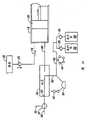
图2A-2G是例示图1所示系统的操作的示意图。2A-2G are schematic diagrams illustrating the operation of the system shown in FIG. 1 .
图3是图1所示注射器系统的控制系统的电结构图。FIG. 3 is an electrical block diagram of the control system of the injector system shown in FIG. 1 .
图4例示了注射器系统的优选实施例的前面板控制器和显示器。Figure 4 illustrates the front panel controls and display of a preferred embodiment of the injector system.
图5A和5B是图1所示系统的远程控制器的侧视图和局部俯视立体图。5A and 5B are side and partial top perspective views of the remote controller of the system shown in FIG. 1 .
图6是脚踏远程控制器的立体图。Figure 6 is a perspective view of the foot remote controller.
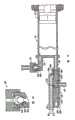
图7A-7D例示了入口止回阀和歧管在造影剂填充、空气清理和病人注射操作过程中的操作。7A-7D illustrate the operation of the inlet check valve and manifold during contrast fill, air purge, and patient injection operations.
图8A-8C例示了入口止回阀的更详细的操作。8A-8C illustrate more detailed operation of the inlet check valve.
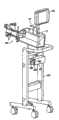
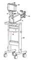
图9A和9B是例示血管造影注射器系统的第二实施例结构的立体图。9A and 9B are perspective views illustrating the structure of a second embodiment of the angiographic injector system.
图10是例示图9中公开的系统的一部分的安装结构的机械结构图。FIG. 10 is a mechanical structure diagram illustrating a mounting structure of a part of the system disclosed in FIG. 9 .
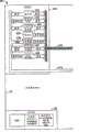
图11A和11B是图9和10所示系统的控制系统和电功能的电结构图。11A and 11B are electrical block diagrams of the control system and electrical functions of the system shown in FIGS. 9 and 10 .
图12是图11所示控制系统的注射器马达控制部分的电结构图。FIG. 12 is an electrical block diagram of the injector motor control portion of the control system shown in FIG. 11 .
图13是图11所示控制系统的蠕动泵马达控制部分的相关安全电路的电结构图。Fig. 13 is an electrical structural diagram of the relevant safety circuit of the peristaltic pump motor control part of the control system shown in Fig. 11 .
图14是图11所示系统的显示器的通电屏幕的示意图。14 is a schematic illustration of a power-on screen of the display of the system shown in FIG. 11 .
图15是图11所示系统的显示器的后校准屏幕的示意图。15 is a schematic illustration of a post-calibration screen of the display of the system shown in FIG. 11 .
图16是图11所示系统的显示器的检测屏幕的示意图。FIG. 16 is a schematic diagram of a detection screen of the display of the system shown in FIG. 11 .
图17是图11所示系统的显示器的前校准屏幕的示意图。FIG. 17 is a schematic illustration of the front calibration screen of the display of the system shown in FIG. 11 .
图18是图11所示系统的显示器的第一启动指令屏幕的示意图。FIG. 18 is a schematic diagram of a first start-up instruction screen of the display of the system shown in FIG. 11 .
图19是图11所示系统的显示器的第二启动指令屏幕的示意图。FIG. 19 is a schematic diagram of a second start-up instruction screen of the display of the system shown in FIG. 11 .
图20是图11所示系统的显示器的第三启动指令屏幕的示意图。FIG. 20 is a schematic diagram of a third start-up instruction screen of the display of the system shown in FIG. 11 .
图21是图11所示系统的显示器的第四启动指令屏幕的示意图。FIG. 21 is a schematic diagram of a fourth start-up instruction screen of the display of the system shown in FIG. 11 .
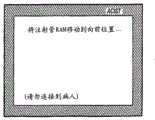
图22是图11所示系统的显示器的准备填充注射管屏幕的示意图。22 is a schematic illustration of a ready to fill syringe screen of the display of the system shown in FIG. 11. FIG.
图24是图11所示系统的显示器的清理通告屏幕的示意图。FIG. 24 is a schematic diagram of a cleanup notification screen of the display of the system shown in FIG. 11 .
图25是图11所示系统的显示器的线路清理指令屏幕的示意图。FIG. 25 is a schematic diagram of a line clearing instruction screen of the display of the system shown in FIG. 11 .
图26是图11所示系统的显示器的清理线路通告屏幕的示意图。FIG. 26 is a schematic diagram of a clear line announcement screen of the display of the system shown in FIG. 11 .
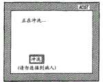
图27是图11所示系统的显示器的最终的盐水冲洗指令屏幕的示意图。27 is a schematic illustration of the final saline flush instruction screen of the display of the system shown in FIG. 11 .
图28是图11所示系统的显示器的盐水冲洗通告屏幕的示意图。28 is a schematic illustration of a saline flush notification screen of the display of the system shown in FIG. 11 .
图29是图11所示系统的显示器的最终的启动屏幕的示意图。FIG. 29 is a schematic illustration of the final start-up screen of the display of the system shown in FIG. 11 .
图30是图11所示系统的主显示器屏幕的示意图。FIG. 30 is a schematic diagram of the main display screen of the system shown in FIG. 11 .
图31是图30所示主显示器屏幕的示意图,其中例示了注射模式中的操作。Figure 31 is a schematic illustration of the main display screen shown in Figure 30 illustrating operation in the injection mode.
图32是图30所示主显示器屏幕的示意图,其中例示了当选择固定速度的操作模式时所显示的键区。32 is a schematic diagram of the main display screen shown in FIG. 30 illustrating the keypad displayed when the fixed speed mode of operation is selected.
图33是图30所示主显示器屏幕的示意图,其中例示了当选择可变速度的操作模式时所显示的键区。33 is a schematic diagram of the main display screen shown in FIG. 30 illustrating the keypad displayed when the variable speed mode of operation is selected.
图34是图30所示主显示器屏幕的示意图,其中例示了在手动清理模式中的操作。FIG. 34 is a schematic diagram of the main display screen shown in FIG. 30 illustrating operation in the manual cleaning mode.
图35是图30所示主显示器屏幕的示意图,其中例示了在手动补充模式中的操作。FIG. 35 is a schematic view of the main display screen shown in FIG. 30 illustrating operation in the manual replenishment mode.
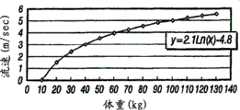
图36A-C例示了通过与病人体重相关的算法确定的流速极限的默认注射参数值的对比图线。36A-C illustrate plots comparing default injection parameter values for flow rate limits determined by an algorithm related to patient weight.
图37A-C例示了通过与病人体重相关的本发明的算法确定的流量极限的默认注射参数值的对比图线。37A-C illustrate comparative plots of default injection parameter values for flow limits determined by the algorithm of the present invention in relation to patient weight.
图38是例示用于确定图36和37所示与病人相关的默认注射参数的过程的示意性流程图。FIG. 38 is a schematic flow diagram illustrating a process for determining the patient-related default injection parameters shown in FIGS. 36 and 37 .
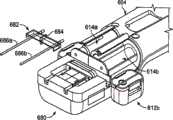
图39A-C是根据一个实施例的动力双注射管造影剂注射系统的视图。39A-C are views of a powered dual syringe contrast injection system, according to one embodiment.
图40A-B和41A-B是可用于动力注射系统中的一次性流体连接器的特定实施例的立体图。40A-B and 41A-B are perspective views of certain embodiments of disposable fluid connectors that may be used in power injection systems.
图42是根据一个实施例包括注射管和蠕动泵的动力注射系统的立体图。Figure 42 is a perspective view of a powered injection system including a syringe and a peristaltic pump, according to one embodiment.
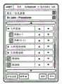
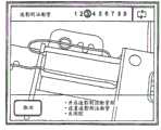
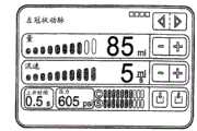
图43-图54例示了可设置在动力注射系统中图形用户界面(GUI)内的屏幕显示的各种实施例。43-54 illustrate various embodiments of screen displays that may be provided within a graphical user interface (GUI) in a power injection system.
图55A是可用于动力注射系统的阀的一个实施例的立体图。Figure 55A is a perspective view of one embodiment of a valve that may be used in a power injection system.
图55B是可用于动力注射系统的阀的另一实施例的立体图。Figure 55B is a perspective view of another embodiment of a valve that may be used in a power injection system.
图56是可用于动力注射系统的手动控制器的一个实施例的立体图。Figure 56 is a perspective view of one embodiment of a manual control that may be used with a power injection system.
具体实施方式Detailed ways
通过在此进行的更详细的描述将认识到的是,本发明的各种实施例的原理可应用于多种不同的自动注射器系统物理结构。这类系统的示例将在下文中大致描述。参见各附图,图1显示了注射器系统10,用于在交互的医生控制下将射线照像造影材料注射到血管中。系统10包括主控制台12,手持式远程控制器14,注射管保持器16,注射管主体18,注射管柱塞20,射线照像材料储器(瓶)22,单向阀24,歧管26,高压管28,导管30,病人给药端口32,三通旋塞34,T连接器36,压力传感器38,旋塞40,管路42,蠕动泵44,盐水止回阀46,废料止回阀48,盐水袋52,和袋支撑架54。As will be appreciated from the more detailed description presented herein, the principles of the various embodiments of the invention are applicable to a variety of different autoinjector system physical configurations. Examples of such systems are generally described below. Referring to the drawings, Figure 1 shows an
控制台12容纳用于系统10的电子控制器以及驱动活塞20和蠕动泵44的马达。在控制台12的前表面上,用户界面55提供控制开关56和显示器58,由此,用户可进入控制设置并监控系统10的操作状态。控制台可为自立式的,且优选地设置为安装在运输车组件上。Console 12 houses the electronic controls for
通过适合的电源为系统的所有电子部件提供电力,此电源还设置为与主电源安全地电隔离。此电源可位于控制台12内,但优选地与控制台12分开安装,即安装在墙上或安装车上。All electronic components of the system are powered by a suitable power supply, which is also set to be safely galvanically isolated from the mains power supply. This power supply may be located within the
远程控制器14通过缆线60连接到控制台12(不过,在其他实施例中,远程控制器14可通过诸如RF、红外光或超声联结等无线连接方式进行连接)。远程控制器14在如图1所示的实施例中为手持式控制器,并且包括重置开关62、盐水推进钮开关64和流速控制杆或触发器66。通过按压触发器66,用户可将命令信号提供到控制台12以提供连续可变的注射速度。The
注射管保持器16从控制台12的左手侧突出。注射管保持器16优选地由洁净材料制成,并包括半柱形背壳68、半柱形前门70(在图1中显示为打开位置)和储器保持器72。Projecting from the left hand side of the
注射管18是透明或半透明的塑料柱,其开放端74连接到控制台12。注射管18的封闭端76包含两部分:上部分78和下部分80。
柱塞20在注射管主体18内可移动。柱塞20连接到位于控制台12内的马达并由此马达驱动。A
射线照像造影材料储器22通过单向止回阀24连接到上部分78。射线照像造影材料从储器22通过止回阀24和上部分78被吸引到由注射管主体18和柱塞22限定的泵送腔中。止回阀24优选地为受力的单向阀,其允许空气从注射管主体18流回到储器22中,但不允许射线照像造影材料从注射管主体18流到储器22中。这允许系统的自动空气清理,这将在下文中更详细地描述。The radiographic
注射管主体18的下部分80连接到歧管26。歧管26包括弹簧偏置滑阀,所述滑阀通常连接传感器/盐水端口82与病人端口84。当将注射射线照像造影材料时,射线照像材料的压力导致滑阀改变状态,使得下部分80连接到病人端口84。The
高压管28是将病人端口84连接到导管30的柔性管。三通旋塞34位于管28的远端。可旋转的鲁尔锁定连接器86连接到旋塞34并与在导管30近端的鲁尔连接器88配合。旋塞34可阻塞在管28与导管30之间的流通,而允许给药端口32至导管30的流通或连接。
除了通过导管30将射线照像材料注射到病人体内,系统10还允许执行其他相关功能。当即将通过导管30将给药传输到病人时,可以将用于传输病人给药的装置(在图1中未示出)连接到给药端口32。In addition to injecting radiographic material into the patient through
当导管30在病人体内就位而尚未进行射线照像造影材料注射时,压力传感器38通过从导管30、管28、病人端口84、歧管26、传感器/盐水端口82、管路90、T连接器36和管路92延伸的流体柱来监控血压。传感器38具有相关联的旋塞40,旋塞40允许传感器38在校准过程中暴露于大气压,并允许去除/排出存留的空气,因而传感器38的拱顶腔可进行盐水冲洗。When the
蠕动泵44从袋50中将盐水溶液通过盐水止回阀46、管路42、T连接器36和管路90供应到盐水端口82。当蠕动泵44操作以供应盐水溶液时,盐水溶液通过歧管26供应到病人端口84,并之后通过管28供应到导管30。
蠕动泵44还反向操作而从导管30吸取流体,流体通过管28、歧管26、管路90、T连接器36和管路42至废料止回阀48并之后进入废料收集袋52中。
在本发明的优选实施例中,注射管主体18、歧管26、管28、拱顶30、T连接器36、管路42、止回阀46和48、袋50和52、以及管路90和92均为一次性物件。每次为新的病人执行血管造影术过程时,这些物件必须安装在系统10中。一旦系统10通过所安装的所有一次性物件而设定,则门70关闭,注射管主体19被充以造影材料并清理空气,用户(通常为医生)进入系统10中,并将安全参数应用于射线照像造影材料注射。这些安全参数通常包括在任一注射过程中射线照像造影材料的注射最大量、注射最大流速、注射管主体18内施加的最大压力、和注射的最大上升时间或加速度。为了致动造影材料注射,用户通过压下触发器66操作远程控制器14。在预设安全参数的范围内,系统10使注射流速随着触发器66的行进力或距离的增加而增加。In a preferred embodiment of the invention,
通常,用户将使用荧光透视法或其他成像方法根据连续观测造影剂流出进入被注射结构而计量所注射的造影材料的速率的量。系统10允许用户使造影剂注射适应于病人需要,由此使所述过程的质量最佳化,增加了安全性,并减少了进行荧光透视法检查所需的造影材料的量。Typically, the user will use fluoroscopy or other imaging methods to meter the amount of the rate of injected contrast material based on continuous observation of the outflow of contrast material into the injected structure.
图2A-2G的示意图例示了系统10的七种不同操作过程中的流体流径。这些操作是:造影剂填充(图2A)、空气清理(图2B)、对病人注射(图2C)、对病人施压(图2D)、盐水冲洗(图2E)、抽吸废料(图2F)、和对病人给药(图2G)。2A-2G are schematic diagrams illustrating fluid flow paths during seven different operations of
在图2A中所示的造影剂填充操作包括:将注射管主体18填充来自储器(造影介质供应器)22中的射线照像造影材料。造影剂填充操作在系统10初始设定时执行,并可在系统10的操作过程中当注射管主体18中的射线照像造影材料处于低量的任何时候重复进行。The contrast filling operation shown in FIG. 2A includes filling the
在系统10初始设定时,柱塞20被初始驱动至其邻近于注射管主体18的封闭端的向前最远位置。这将会使处于注射管主体18内的大多数空气排至大气中。Upon initial setting of the
柱塞20然后回缩而在注射管主体18内形成真空,以吸引造影材料从储器22通过止回阀24经由上端口78进入注射管主体18。The
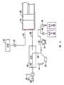
造影剂填充操作通常导致一些空气被吸入或存留在注射管主体18内。显然重要的是,防止空气经由导管30被注射进入病人体内。如图2B中所示的空气清理操作的目的正在于此。而且,处于不同高度处的两端口的位置允许更安全地防止在注射时形成气泡。The contrast filling operation typically results in some air being aspirated or trapped within
在空气清理操作的过程中,柱塞20向前行进以排出驻留在注射管主体18内的空气。空气轻于造影材料,并聚集在注射管主体18的顶部附近。随着柱塞20向前移动,空气从注射管主体18中经由上端口78和单向阀24排出。在图2B所示的实施例中,单向阀24为受力的单向阀,其允许射线照像造影材料从储器22流到上端口78,但不允许射线照像造影材料沿相反方向从上端口78流到储器22。不过,阀24将允许空气从端口78流到储器22。一旦射线照像造影材料开始从注射管主体18经由上端口78流向阀24,则阀24关闭以阻止朝向储器22的任何进一步流动。During an air purge operation,
在可替代实施例中,阀24也可以是在控制台12内电路的控制下的螺线管致动的或马达驱动的阀。在任一情况下,阀24能够承受在注射操作过程中对其施加的相对较高压力。优选地,阀24能够承受高达约1200psi的静流体压力。In alternative embodiments,
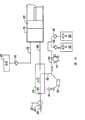
图2C例示了对病人注射操作。柱塞20在用户的交互控制下向前行进,其中用户控制远程控制器14的触发器66。柱塞20的运动形成液压力,以将造影材料压出注射管主体18而经由下端口80且经由歧管26和高压管28进入导管30中。如图2C中所示,注射管下端口80和病人端口84相连用于在对病人注射操作中使流体流通。Figure 2C illustrates the injection procedure for a patient. The
歧管26包含一阀,用于控制在病人端口84与注射管下端口80或传感器/盐水端口82之间的流体连接的路线。在本发明一个实施例中,歧管26包括滑阀,该滑阀通过弹簧偏置而使病人端口84一般连通到传感器/盐水端口82(如图2A和2B中所示)。当随着柱塞20向前运动而在注射管下端口80处累积压力时,克服对于滑阀的偏置力,使得注射管下端口80连接到病人端口84,而传感器/盐水端口82与歧管26内的阀断开连接以保护压力传感器38免于暴露于由于对病人注射操作所产生的高压力。
在对病人注射操作过程中,滑阀响应于从注射管下端口80施加于该滑阀上的渐增压力而自动打开。当在每一次对病人注射操作结束时通过柱塞20回缩而施加轻度真空时,滑阀关闭并返回其原来位置,从而允许病人端口84连接到传感器38。The spool valve automatically opens in response to increasing pressure applied to the spool valve from the
在可替代实施例中,歧管26内的阀是电动机械的或马达驱动的阀,并在适合的时候致动以将注射管下端口80或传感器/盐水端口82连接到病人端口84。致动器机构通过控制台12进行控制。在此可替代实施例中,同样地,所述阀保护压力传感器38免于暴露于高压力。In an alternative embodiment, the valves within
图2D例示了对病人施压操作。系统10允许读取病人的血压,并且通过导管30监控血压。可以在除了对病人注射、盐水冲洗和抽吸废料操作以外的任何时候通过使用压力传感器38监控病人血压。通过压力传感器38产生的压力读数可通过手动打开旋塞40和关闭旋塞34以将压力传感器38暴露于大气压力而得以标准化。Figure 2D illustrates the operation of applying pressure to the patient.
在如图2E中所示的盐水冲洗操作过程中,盐水溶液用于冲洗所有内部线路、压力传感器腔38、管28和导管30。如图2E中所示,蠕动泵44沿着使盐水溶液从袋50被吸引通过止回阀46并通过管路42而至盐水端口82的方向操作。歧管26将盐水端口82连接到病人端口84,使得盐水溶液被泵送出病人端口84并通过管路28和导管30。During a saline flush operation as shown in FIG. 2E , a saline solution is used to flush all internal lines,
在抽吸废料操作过程中,病人端口84再次连接到盐水端口82。在此操作过程中,蠕动泵44沿着与其在盐水冲洗操作过程中旋转的相反方向操作。其结果是,病人流体从病人端口84被抽吸至盐水端口82,并然后经由管路42和止回阀48进入废料收集袋52中。蠕动泵44用作一种阀,用于夹紧/闭塞管路42并防止与止回阀46和48关联的盐水和废料容器50和52往来回流。
当导管30在病人体内就位时,所希望的是,可以为病人提供给药。系统10通过提供病人给药端口32而允许这种选择。如图2G中所示,当旋塞34打开时,连接到端口32的给药源将连接到病人端口84,并且由此连接到导管30。在对病人给药操作中,蠕动泵44和柱塞20不移动。With the
图3是已用于上述血管造影注射器系统的控制系统的电结构图。图3所示电控制系统包括单一的数字电脑100,电脑100通过接口102接收来自远程控制器14和前面板控制器56的输入信号,并向显示器58提供信号用于显示操作数据、警报、状态信息和操作者提示。以下优选实施例将描述改进的电控制系统;不过,在此描述的单一电脑系统完成包含上述血管造影注射器系统10各部件的血管造影注射器系统的功能性描述。FIG. 3 is an electrical block diagram of a control system that has been used in the above-described angiography injector system. The electrical control system shown in FIG. 3 includes a single
电脑100通过包含马达104、马达放大器106、转速计108、电位计110、整流器112、压敏测压单元114和A/D转换器116的马达驱动电路控制柱塞20的运动。
马达放大器106响应于来自电脑100的控制电压、向前/向后、和/制动信号以及来自转速计108经由整流器112的速度反馈信号而向马达104提供驱动器1信号。转速计108和电位计110的输出作为速度监控和位置监控信号通过A/D转换器116提供到电脑100。这允许电脑100检查马达速度、马达方向和位置(容量为计算值)。
压力感应器114检测马达电流或柱塞力以测量施加于注射管主体18内射线照像造影材料的压力。这种压力监控信号通过A/D转换器116和接口102提供到电脑100。
蠕动泵44在电脑100的控制下通过泵马达120、马达驱动器122和光学编码器124驱动。电脑100将盐水(向前)和废料(向后)驱动信号提供到马达驱动器122,以沿用于盐水冲洗的向前方向和沿用于废料抽吸的向后方向操作泵马达120。光学编码器124将速度方向监控信号提供到接口102,用以同时指示泵马达120的旋转速度和方向。The
图3例示了控制系统的实施例,其中,阀马达130用于致动各阀,例如单向阀24和歧管26内的阀。在此实施例中,电脑100通过马达驱动器132控制阀马达130,并通过来自电位计134的位置监控反馈信号而监控位置。在此具体实施例中,阀马达130为分级马达。FIG. 3 illustrates an embodiment of a control system in which a
电脑100根据来自温度感应器140的温度控制信号监控造影材料的温度。温度感应器140优选地位于注射管主体18附近。如果通过温度感应器140检测到的温度过高,则电脑100将使马达104操作不能进行,从而停止对病人注射。如果温度过低,则电脑100将一温度起动驱动器信号提供到加热器驱动器150,以起动加热器152。在一个优选实施例中,加热器152是位于注射管保持器116内且邻近于注射管主体18的电阻膜加热器。The
电脑100还接收来自造影剂瓶感应器160、向前极限感应器162、向后极限感应器164、注射管缺失感应器166、腔开放感应器168、无造影剂气泡探测器170和线路中空气气泡探测器172的反馈信号。The
造影剂瓶感应器160是位于储器保持器72内的微型开关。来自感应器160的造影剂瓶存在信号的状态指示储器22是否在保持器72内就位。如果储器22不存在,则电脑100将使填充操作不能进行。The
向前极限感应器162和向后极限感应器164检测柱塞20的端极限位置。当柱塞20到达其向前极限位置时,不允许柱塞20进一步向前运动。类似地,当向后极限感应器164指示柱塞20已经到达其向后极限位置时,不允许其进一步向后运动。The
注射管缺失感应器166为微型开关或红外发射器/探测器,用于指示注射管主体18是否在注射管保持器16内就位。如果注射管主体18未就位,则除了柱塞20可移动到其向后极限位置(即,返回零点)以外,所有运动功能均不能进行。
腔开放感应器168为微型开关或红外发射器/探测器,用于检测注射管保持器16的门70是否打开。当来自感应器168的信号指示了门70打开时,所有运动功能均不能进行。仅当门70关闭并锁定时,才可以允许某种运动。当指示了门70关闭且感应器166指示了注射管主体18就位时,系统10的其他正常功能可以进行。Cavity
气泡探测器170位于储器22与上端口78之间,并且优选地为检测空气气泡的红外发射器/探测器。如果在填充操作过程中在储器22与上端口78之间的流径中检测到存在空气气泡,则使填充操作不能进行,直到连接好新的储器。
气泡探测器172定位用于检测在高压线路28中的空气气泡。气泡探测器172优选地为红外发射器/探测器类型的气泡探测器。在高压线路28中检测到任何空气气泡导致所有流体推出功能不能进行,无论此流体是来自蠕动泵44的盐水溶液还是来自注射管主体18的造影材料。
图3所示控制系统还能够通过受控于电脑100的继电器180将控制信号提供到x射线设备。此外,电脑100还接收来自血压传感器38的数据和来自分离于注射器系统10的心电图仪(ECG)系统的数据。压力和ECG信号通过信号调节器和A/D转换器190接收,并传输到电脑100。在一个优选实施例中,电脑100使用ECG信号而使得马达104的操作(以及对病人注射操作)与心跳同步。The control system shown in FIG. 3 can also provide control signals to the x-ray equipment through the relay 180 controlled by the
在心舒期中(此时心脏处于收缩状态之间),血液主要流向心脏。在心缩期中(此时心脏收缩)连续注射造影材料可导致造影材料溢出至主动脉中。通过主要在心舒期中注射,可减少造影剂剂量,而不损害将造影剂注射到冠状动脉中的过程的完整性。During diastole (when the heart is between contractions), blood flows primarily to the heart. Continuous injection of contrast material during systole (when the heart contracts) can result in overflow of contrast material into the aorta. By injecting primarily in diastole, the contrast dose can be reduced without compromising the integrity of the process of contrast injection into the coronary arteries.
在优选实施例中,射线照像造影材料的注射与冠状动脉血流同步。心缩期和心舒期的时间周期可以使用心电图(ECG)电信号、动脉血压波形分析或其他基于心跳速率的时序而确定。通过控制马达104的速度、柱塞20的速度以及运动,造影材料注射在心缩期阶段中断,以在这段时间中减少或停止造影剂注射。结合远程控制器14,操作者可改变造影剂注射到冠状动脉中的速率,而同时电脑100使造影剂注射相对于心脏循环而自动脉动。In a preferred embodiment, the injection of the radiographic contrast material is synchronized with coronary blood flow. The time periods of systole and diastole may be determined using electrocardiogram (ECG) electrical signals, arterial blood pressure waveform analysis, or other heart rate-based timing. Contrast material injection is interrupted during the systolic phase by controlling the speed of
运动中的造影材料的惯性力以及保持造影材料并将其传送给病人的容器和管路的膨胀,可能导致在注射管主体18内的柱塞20的运动与造影材料从导管30进入病人体内的运动之间的相位滞后。为了调节在柱塞20运动与造影剂排入病人体内之间的相位滞后,可通过控制面板54输入可变时间补偿值,使得心脏周期的时序可以通过选定的时间进行补偿。由于相位滞后的量级可取决于心跳速率频率,因此,电脑100内的算法根据注射造影材料过程中的即时心跳速率而连续且自动地调节时间补偿值的量级。The inertial forces of the contrast material in motion and the expansion of the container and tubing that hold the contrast material and deliver it to the patient may cause the movement of the
图4显示了控制面板54的一个实施例,其中例示本发明一个实施例的前面板控制开关56和显示器58。前面板控制开关56包括:设定/填充/结束开关200、清理开关202、抽吸开关204、盐水开关206、起动OK开关208、注射量极限开关210a和210b、注射速率极限开关212a和212b、注射压力极限开关214a和214b、上升时间开关216a和216b、OK开关218、注射范围拨动开关220、大注射OK开关222、和停止开关224。Figure 4 shows one embodiment of a
设定/填充/结束开关200是瞬时按钮开关。当开关200首次启动时,将通知用户将注射管18放置在注射管保持器16中。当注射管18已经放置在注射管保持器16中(这将通过感应器166指示电脑100)时,将指示用户关闭和锁定所述腔(即,关闭门70)。柱塞20移动到其向前最远位置,从而将注射管内的所有空气排出。显示器58然后指示操作者应连接造影剂储器22。一旦造影剂储器22已被放置就位,则需要操作者按下OK开关218,此时柱塞20将以设定速率(优选地对应于10毫升/秒的流速)回缩至达到注射管最大容量。如果实际速率(如通过从A/D转换器116向电脑100反馈所示)大于所设定的速率,则系统10将停止。Set/Fill/End switch 200 is a momentary push button switch. When the switch 200 is first activated, the user will be notified to place the
一旦柱塞20处于其向后最远位置,则马达104致动而使柱塞向前移动以清理所有空气气泡。压力感应器114提供单向阀24何时关闭的指示,压力开始在注射管主体18内累积。一旦清理完成,则注射总量和注射次数计数被重置。Once the
将开关200致动还允许Ml收缩并允许柱塞20与注射管主体18脱离接合。Actuating the switch 200 also allows M1 to retract and allow the
清理开关202是受保护的瞬时按钮开关。清理开关202当启动时使柱塞20向前移动以将空气通过上端口78排出。柱塞20的向前移动受限制并当达到注射管18内的预定压力时停止。这通过压力感应器114检测。通过清理开关202启动的清理操作将排出注射管18内的空气。用户也可以使用清理开关202并通过按下清理开关202且持续保持其状态而清理通过病人端口84的流体。Purge switch 202 is a protected momentary push button switch. Purge switch 202 , when actuated, moves
抽吸开关204是瞬时按钮开关,其导致电脑100启动蠕动泵44的泵马达120。泵马达120操作而以设定速度抽吸导管30内的物质,其中抽吸的流体被收集在废料袋52中。在抽吸过程中,所有其他运动功能脱离接合。如果马达120的实际速度大于设定速度,则电脑100将使马达120停止。Suction switch 204 is a momentary push button switch that causes
盐水开关206是交替动作开关。泵马达120响应于盐水开关206的按动而启动,来自袋50的盐水溶液以设定速度被引入歧管26和导管30中。如果盐水开关206在10秒内并未第二次按下以停止盐水溶液流动,则电脑100自动停止泵马达120。如果发生超时,则盐水开关206必须在启动任何进一步的动作之前重置到其原来的状态。The saline switch 206 is an alternate action switch.
起动OK开关208是瞬时按钮开关。当系统在注射结束时已探测到禁止功能而并非检测到达到极限,则在启动OK开关218并启动任何进一步的功能之前必须启动起动OK开关208。Start OK switch 208 is a momentary push button switch. When the system has detected inhibiting the function at the end of the injection but not detecting that the limit has been reached, the activate OK switch 208 must be activated before activating the OK switch 218 and enabling any further functions.
注射量极限键210a和210b被按压以增大或减小系统将在任一注射中注射的最大注射量。键210a使最大量值增大,而键210b使最大量值减小。一旦最大注射量极限被设定,如果测得的量达到设定值,则电脑100将使马达104停止,并将不重启,直到压下OK开关218。如果已选定大的注射(即,大于10毫升),则OK开关218和大注射OK开关220在启动大注射之前必须均重置。Injection volume limit keys 210a and 210b are pressed to increase or decrease the maximum injection volume that the system will inject in any one injection. Key 210a increases the maximum magnitude and key 210b decreases the maximum magnitude. Once the maximum injection volume limit is set, if the measured volume reaches the set value, the
注射速率极限键212a和212b允许医生选择在任一注射中系统可以达到的最大流速。如果测得的速率(该速率通过来自转速计108和电位计110的反馈信号确定)达到设定值,则电脑100将控制马达104而将流速限制到设定值。Injection rate limit keys 212a and 212b allow the physician to select the maximum flow rate the system can achieve in any one injection. If the measured rate (determined by feedback signals from the
注射压力极限键214a和214b允许医生选择在任一注射中系统可以达到的最大压力。如果测得的压力(如通过压力感应器114确定的压力)达到设定值,则电脑100将控制马达104而将压力限制到注射压力极限。注射速率也将由此受到限制。Injection pressure limit keys 214a and 214b allow the physician to select the maximum pressure the system can achieve in any one injection. If the measured pressure (as determined by the pressure sensor 114) reaches the set point, the
上升时间键216a和216b允许医生选择在任一注射中当流速改变时系统允许的上升时间。电脑100控制马达104而将上升时间限制到设定值。Rise time keys 216a and 216b allow the physician to select the rise time the system will allow as the flow rate changes in any one injection. The
在可替代实施例中,键210a-210b、212a-212b、214a-214b和216a-216b可更换为用于选择数字值的其他装置。这些装置包括:选择盘、数字键盘、触摸屏。In alternative embodiments, the keys 210a-210b, 212a-212b, 214a-214b, and 216a-216b may be replaced with other means for selecting numeric values. These devices include: selection dial, numeric keypad, touch screen.
OK开关218是重置各功能和硬件感应器的瞬时按钮开关。电脑100响应于OK开关218的启动而控制显示器58要求操作者确认所选定的正确功能。启动OK开关218导致状态被设置为就绪。OK switch 218 is a momentary push button switch that resets functions and hardware sensors. In response to actuation of the OK switch 218, the
注射范围开关220是拨动开关。根据开关220是否处于“小”或“大”的位置,为下一次注射选择高或低的注射量范围。Injection range switch 220 is a toggle switch. Depending on whether switch 220 is in the "small" or "large" position, a high or low injection volume range is selected for the next injection.
大注射OK开关222是瞬时按钮开关。当已通过注射范围开关220选定大注射范围时,大注射OK按钮222必须启动用以使OK开关219能够工作。OK开关218必须在每一注射之前启动。在进行大量注射时,需要用户通过启动第一大注射OK开关222并之后启动OK开关218来确认所选定的量。Large Shot
停止开关224是瞬时按钮开关。当按动停止开关224时,使得所有功能不能进行。显示器58保持能够显示的状态。The stop switch 224 is a momentary push button switch. When the stop switch 224 is pressed, all functions are disabled. The
显示面板58包括设定显示器250、状态显示器252、警报显示器254、极限显示器256、注射总数显示器260、注射总量显示器262、流速显示器264、注射量显示器266、注射量极限显示器268、注射速率极限显示器270、压力极限显示器272、最小上升时间显示器274、大注射显示器276、和实时时钟显示器278。
当操作者进行设定过程时,设定显示器250包含一系列消息。在设定显示器250中的消息显示通过如前所述地致动设定开关200而启动。The
状态显示器252提供多种不同操作状况之一的闪烁指示。在图4中所示实施例中,这些可显示的状态状况包括:“就绪”、“设定”、“注射”、“填充”、“冲洗”和“抽吸”。Status display 252 provides a blinking indication of one of a number of different operating conditions. In the embodiment shown in FIG. 4, these displayable status conditions include: "Ready", "Set", "Inject", "Fill", "Flush", and "Aspiration".
警报显示器254和极限显示器256通知操作者如下状况:系统10遭遇临界控制参数并将不能进行操作,或系统10达到上极限或下极限并将以受限制方式继续作用,或系统10达到上极限或下极限并将继续工作。Alarm display 254 and limit display 256 notify the operator of the following conditions:
注射显示器260的总数显示了为当前病人情况提供的(累积)注射总数。在当前病人情况中的累积总量通过总量显示器262显示。The total number of injections display 260 shows the (cumulative) total number of injections provided for the current patient condition. The cumulative total in the current patient condition is displayed via the total display 262 .
显示器264和266提供对于当前或上一次注射的信息。显示器264显示在注射过程中对病人的实时流速的数字值。一旦注射完成,则显示器264上所显示的值表示在此注射过程中达到的流速峰值。显示器266显示在最近的注射过程中注射量的数字值。Displays 264 and 266 provide information on the current or last injection. Display 264 displays digital values of the real-time flow rate to the patient during the injection. Once the injection is complete, the value shown on display 264 represents the peak flow rate achieved during the injection. Display 266 shows the numerical value of the injection volume during the most recent injection.
显示器268显示了通过操作开关210a和210b所选定的最大注射量的数字值。类似地,显示器270显示了通过开关212a和212b所选定的系统允许的最大流速的数字值。显示器272显示了系统允许在注射管18中形成的最大压力的数字值。压力极限通过开关214a和214b选定。Display 268 shows the numerical value of the maximum injection volume selected by operating switches 210a and 210b. Similarly, display 270 shows a numerical value for the maximum flow rate allowed by the system selected by switches 212a and 212b. Display 272 shows a numerical value for the maximum pressure the system allows to develop in
显示器274显示了当改变流速时系统允许的最小上升时间。最小上升时间通过开关216a和216b选定。Display 274 shows the minimum rise time allowed by the system when changing the flow rate. The minimum rise time is selected by switches 216a and 216b.
当操作者已选定了大注射级别时,显示器276提供清晰指示。Display 276 provides a clear indication when the operator has selected a large injection level.
实时时钟显示器278以小时、分钟和秒显示了当前时间。Real time clock display 278 shows the current time in hours, minutes and seconds.
图5A和5B显示了远程控制器14的一个实施例,其包括设计为符合用户的手的主壳体300。触发器66相对于壳体300可移动,而触发器66的位置产生随触发器位置而变化的命令信号。在一个实施例中,触发器66联接到壳体300内的电位计。命令信号控制指令流动速率或速度。流速直接成比例于触发器位置。Figures 5A and 5B show one embodiment of the
重置开关62是瞬时按钮开关,其功能与OK开关218相同。可替代地,重置开关62也可被标为“OK”。
在远程控制器14上的盐水开关64是交替动作按钮开关,此开关被按动而开通并被再次按动而关断。盐水开关62的功能与在前面板54上的盐水开关206相同。The
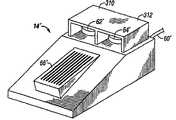
如本发明另一实施例中所示,采用脚踏形式的可替代的远程控制器14’用于替代如图1以及图5A和5B中所示的手持式远程控制器14。脚踏控制器14’包括用于提供命令信号的脚操作速度踏板或触发器66’以及重置或OK开关62’和盐水开关64’。盖310和312保护开关62’和64’,使得其可仅通过手致动而不会意外通过脚致动。脚踏远程控制器14’通过缆线60’连接到控制台12,但可以可替代地通过无线联接实现连接。As shown in another embodiment of the present invention, an alternative
图7A-7D和图8A-8C例示了在造影剂填充、空气清理和对病人注射操作的过程中单向阀24和歧管26的结构和操作。Figures 7A-7D and Figures 8A-8C illustrate the structure and operation of the one-
图7A和8A例示了在造影剂填充操作过程中的单向阀或止回阀24、歧管26、注射管主体18和柱塞20。入口止回阀或单向阀24包括受力球350,球350位于图7A和7B中的阀腔352内的下方就位位置。造影材料通过柱塞20向后运动被引入注射管主体18中。造影材料流动穿过球350周围的通路354并进入上端口78。7A and 8A illustrate the one-way or
歧管26包含弹簧载荷滑阀360,滑阀360包括阀心主体362、轴364、O形环366、368和370、偏置弹簧372和保持器374。如图7A中所示,在造影剂填充操作过程中,偏置弹簧372促使阀心主体362至其朝向注射管主体18的最右位置。在此位置,阀心主体362阻塞注射管主体18的下端口80,而同时通过斜通路376将传感器盐水端口82连接到病人端口84。一方面的O形环366和368以及另一方面的O形环370位于斜通路376的相反侧上以提供流体密封。
图7B和8B例示了空气清理操作。注射管主体18已被填充以造影剂流体,但还具有滞留空气。柱塞20被驱动向前以将空气通过上端口78并通过止回阀24压出注射管主体18之外。空气的力可导致止回阀20中的球350略微升起。不过,球350足够重,使得被压出注射管主体18之外并朝向储器22返回的空气不能将球350升起至其最上就位位置而在此处阻塞空气流出注射管主体18。Figures 7B and 8B illustrate the air purge operation.
在空气清理操作过程中,滑阀360处于与图7A中相同的位置。斜通路376将传感器盐水端口82与病人端口84相连。其结果是,通过压力传感器38的压力监控可在空气清理(以及造影剂填充)操作过程中进行。During air purge operation,
图7C和8C例示了在空气清理操作结束时和在对病人注射操作开始时歧管26和止回阀24的状态。7C and 8C illustrate the state of the manifold 26 and
在图7C中,所有空气已经从注射管主体18中排出。球350可浮在射线照像造影材料上,使得当所有空气已经被去除且射线照像造影材料开始流出注射管主体18并通过上端口78至阀腔352时,球350向上移动至其上就位位置。球350阻塞任何射线照像造影材料的连续向上流动,如图7C和8C中所示。In FIG. 7C all air has been expelled from the
在图7C中所示的状态中,注射管主体18内的压力,特别是下端口80中的压力,尚未达到克服弹簧372的偏置力的水平。其结果是,阀心主体362尚未移动到左方,而斜通路376继续连接传感器盐水端口82与病人端口84。In the state shown in FIG. 7C , the pressure within
图7D例示了对病人注射操作。柱塞20向前移动,入口止回阀24关闭。下端口80处的压力变得足够高以克服弹簧372的偏置力。阀心主体362已被驱动到左方,从而使下端口80连接到病人端口84。与此同时,阀心主体362阻塞传感器/盐水端口82。Figure 7D illustrates the injecting operation on a patient. The
通过操作滑阀360,柱塞20和注射管主体18运动所产生的高压直接连接到病人端口84,而盐水端口82和压力传感器38被保护而免于高压。By operating
用于致动的压力在制造后可通过增大或减小注射管预载荷而改变和确定。The pressure for actuation can be varied and determined after manufacture by increasing or decreasing syringe preload.
本领域技术人员应认识到的是,可以配置常用血管造影注射器系统10的其他结构。例如,在名称为“双端口注射管(Dual Port Syringe)”的美国专利6,099,502(在此以参见的方式引入本文)的文献中描述的可替代的注射管和安装系统部分,可用于替换和/或修改以上所述的方案。进一步地,本领域技术人员应认识到的是,可采用其他改进,例如对组件歧管部分的改进,例如,如在名称为“具有自动高/低压开关的血管造影注射器系统(Angiographic Injector System with AutomaticHigh/Low Pressure Switching)”的美国专利6,221,045(在此以参见的方式引入本文)中所述,也可以采用远程控制器14的其他结构。远程控制器组件的许多可替代结构在所引用的申请文件以及名称为“气动控制器和方法(Pneumatic Controller and Method)”的美国专利5,916,165和名称为“手持式气动控制器装置(Hand-Held Pneumatic ControlDevice)”的美国专利D404,717中进行描述,所有这些专利文献在此以参见的方式引入本文。Those skilled in the art will recognize that other configurations of conventional
以上附图所示血管造影注射器系统的可替代实施例结构在图9a和9b中以10’指示。在图9中所示实施例中,血管造影注射器系统10的一些部件的物理位置已重新设置以利于系统使用。例如,在描述的第一实施例中的用户界面54、控制开关56和显示器58已被并入单一的控制面板400中。在所示第二实施例中,控制面板400安装到旋转基底上的控制台或注射器头12’,其可通过用户脱离连接或再连接以优化位置。图9所示结构的机械流程图在图10中例示。参见图9和10,电源59’电路例示为机械安装而与控制台12’分离。控制台和电源安装到整体指示为402的车,车402包括便于移动的轮,并优选地设计为当用于其预计方法时提供稳定性并防止倾翻。所述车使控制台和电源组件能够快速附接和拆除,以允许控制台和电源靠置在装备有配合连接部的床或其他静止装置上。参见图10,手动式控制器14’例示为有效连接到控制面板400,蠕动泵组件44’显示为机械安装到控制台12’。用于保持如之前相对于本发明第一实施例所述的注射管和相关部件的组件整体指示为名称为“安装腔”404的功能块。这些如前所述并且被称为“一次性”物件的部件(即,注射管、注射管主体内的活塞、造影剂阀、病人歧管、造影剂针、和病人血压端口)整体表示为功能块406。An alternative embodiment configuration of the angiography injector system shown in the above figures is indicated at 10' in Figures 9a and 9b. In the embodiment shown in FIG. 9, the physical location of some components of
用于血管造影注射器系统10’的第二优选控制结构的电子功能结构图如图11中所示。多幅图(图11a和图11b)均包括血管造影注射器系统10’的电子控制网络。为了易于描述图11的网络,之前用于第一实施例中相应电子部件的数字,在描述图11中的类似功能电子部件时将不必完全相同。参见图11,控制系统包括两个分立的电脑系统,每一系统具有智能以监测和控制注射器系统的功能。如同之前实施例所述,电脑系统通常接收离子控制面板400的输入信号,并且提供信号以显示数据、警报、状态详细和操作员提示。在优选实施例中,电脑系统包括两个微电脑。整体指示为410的PC处理器用作控制系统的主处理器,整体指示为412的嵌入处理器用作从处理器。通常,主处理器指令嵌入处理器执行命令,但两个处理器均监控所进行的动作。为了安全,两个处理器均用作独立的动作监控器。键功能,例如注射器马达运动和蠕动马达运动,同时通过两个微电脑监控。在优选实施例中,PC处理器410具有386 DOS中央处理单元,而嵌入核处理器412具有HC 16位中央处理单元。应认识到的是,在本发明的精神和意图的范围内,可以使用其他类型的微处理器。An electronic functional block diagram of a second preferred control architecture for angiography injector system 10' is shown in FIG. The various figures (Figs. 11a and 11b) all include the electronic control network of the angiography injector system 10'. For ease of describing the network of FIG. 11 , the numbers previously used for corresponding electronic components in the first embodiment will not necessarily be identical when describing similarly functioning electronic components in FIG. 11 . Referring to Figure 11, the control system consists of two separate computer systems, each with intelligence to monitor and control the functions of the injector system. As with previous embodiments, the computer system typically receives input signals from the
参见图11,应注意的是,PC处理器410通过第一通讯总线414与系统中的电子部件通讯,而嵌入核处理器412通过第二通讯总线416与系统中的电路通讯。两个处理器通过其相应的数据总线和整体指示为417和418的一对通讯寄存器而相互通讯。通常的“监控/动力失效/重置”功能由功能块419指示,ECG所需信息可基于先入先出方式由用于通过两个微处理器进行处理的功能块420收集。通常,系统中不同电子功能块以及两个总线414和416之间的通讯类型,通过与相应电子功能块相关联的图11中各信号流路径并通过这些信号流路内的信号流注释进行指示。Referring to FIG. 11 , it should be noted that the
参见图11,与安装腔404相关联的各种电子功能和检测功能包括:名称为“腔关闭”(422)的感应器,其指示用于将一次性注射管加载到安装腔中的前加载腔门何时关闭;指示为“造影剂排空”(423)的造影剂瓶感应器,其位于并保持器内并指示瓶中是否存在流体;指示为“上、下阀感应器”(424)的两个阀感应器,其用于使电脑确定病人歧管阀和造影剂阀的状态;指示为“EL背灯”(425)的电致发光背灯,其有利于手动探测注射管和一次性物件内的气泡;指示为“造影剂加热器”(426)的加热元件,其位于注射管保持器内并邻近注射管主体;指示为“RTD温度感应器”(427)的一对温度感应器,其位于注射管主体的邻近处,用于提供信号以控制造影剂加热器,从而使造影材料保持相对恒定的温度;和指示为“气泡探测”(428)的空气柱探测感应器,其定位以检测高压线路中的空气,并监控泵送至病人的流体的气泡或空气柱情况。如图11中所示,除了EL背灯425以外,安装腔中的每一感应器与两个处理器均实现通讯。Referring to Figure 11, the various electronic and detection functions associated with the mounting cavity 404 include: a sensor named "Cavity Closed" (422), which indicates the front load for loading a disposable syringe into the mounting cavity When the chamber door is closed; a contrast bottle sensor, indicated as "Contrast Empty" (423), which sits and holds in the holder and indicates whether there is fluid in the bottle; indicated as an "Up and Down Valve Sensor" (424 ), which are used to allow the computer to determine the status of the patient manifold valve and contrast valve; an electroluminescent backlight indicated as "EL backlight" (425), which facilitates manual detection of syringes and Air bubbles within the disposable; heating element indicated as "Contrast Media Heater" (426), located within the syringe holder adjacent to the syringe body; pair of temperatures indicated as "RTD Temperature Sensors" (427) a sensor, located adjacent to the syringe body, for providing a signal to control the contrast medium heater so that the contrast material maintains a relatively constant temperature; and an air column detection sensor indicated as "bubble detection" (428), It is positioned to detect air in the high pressure line and monitor the fluid being pumped to the patient for air bubbles or columns of air. As shown in FIG. 11, except for the
通常,控制面板400包括臂灯430、扬声器431、触摸屏432、显示器433和应急开关434。臂灯430当注射器准备执行注射时点亮。扬声器431是可选特征,可提供与用户的声讯界面交流。在优选实施例中,显示器433为用于显示系统操作状态的液晶(LCD)面板。触摸屏432覆盖在LCD面板上并供用户用于控制系统,这将在下文中更详细地描述。控制面板的所有功能块与PC处理器410直接通讯。应急开关434与两个通讯总线414和416以及将在下文中描述的断流继电器和注射器马达固态继电器直接通讯。Generally, the
手动控制功能块14’包括远程手动控制器单元的电路功能。如前所述,手动控制器是用于以一定方式控制血管造影注射器泵的装置,使得控制器当被用户致动时输出成比例于手动控制装置的位移的电信号。所述控制器是与两个微处理器均通讯的无源电机械装置,如图11中所示。手动控制器包含一对标度接触感应器,所述感应器可远程确定物体位置并用于确定控制器的可手动移动部分的有效行进距离和方位。所述感应器由指示为“模拟霍耳效应”(440)和“数字霍耳效应压电”(441)的两个功能块指示。盐水重置功能通过“盐水重置钮”(442)指示,而指示为“控制类型和连接”(443)的功能块通过手动控制器向微处理器提供设定指示,即系统是否用于执行“固定速率”或“可变速率”注射。在可变速率操作模式下,允许操作者通过手动控制器改变即时注射速率至预定最大流速。在固定操作模式下,当操作者按压手动控制器致动器时,控制器系统将相应地以在注射过程之前已进入控制系统的预定固定速率简单地注射造影材料。The manual
蠕动泵44’在微处理器的控制下通过泵马达和马达驱动器而驱动。整体指示为“PWM控制电路”(450)的马达驱动器,将脉宽调制控制信号提供到蠕动泵马达。电脑将向前(盐水)和向后(废料)驱动信号提供到马达驱动器,以沿用于盐水冲洗的向前方向和沿用于抽吸废料的向后方向而操作泵马达。优选实施例的蠕动泵包括“过速过扭转”感应器451和“断流继电器”452。过速/过扭转感应器451将反馈信号提供到微处理器,以通过泵驱动电路450准确控制蠕动泵的速度。断流继电器452可通过微处理器或通过应急停止开关434启动。The peristaltic pump 44' is driven by the pump motor and motor driver under the control of the microprocessor. A motor driver, generally designated "PWM Control Circuit" (450), provides a pulse width modulated control signal to the peristaltic pump motor. The computer provides forward (salt water) and reverse (waste) drive signals to the motor driver to operate the pump motor in the forward direction for saline flushing and in the reverse direction for aspiration of waste. The peristaltic pump of the preferred embodiment includes an "over-speed and over-torque"
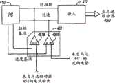
注射器马达460有效连接以移动在注射管内的活塞或擦刷,并受控于“马达控制器”放大器(461)。在优选实施例中,马达驱动器461是标配的伺服放大器,其可通过在下文中描述的多重循环控制结构而准确控制。通常,马达放大器响应于一控制电压而将驱动信号提供到马达。向前、向后和中断信号来自电脑,来自光学编码器的速度反馈信号用于控制速度。监控马达状态,整体由名称为“马达状态过速/过扭转”(462)的功能块指示,用于检测马达速度和位置的独立的光学编码器由“编码器”功能块(463)指示。电位计用于将备份信号提供到嵌入微处理器,以指示马达的绝对“位置”。电位计在结构图中指示为“绝对位置电位”功能块(464)。光学编码器和电位计的输出作为速度监控信号和位置监控信号提供到处理器,而且,允许电脑检查马达速度、马达方向和位置。一对向前和向后极限感应器检测注射管活塞的端极限位置,并通过名称为“F/R极限开关”(465)的功能块指示。当活塞到达其向前极限位置时,不允许进一步的向前运动。类似地,当向后极限感应器指示活塞已到达其向后极限位置时,不允许进一步的向后运动。注射管马达控制器还包括固态继电器(470),用于在来自处理器或应急开关434的命令下使注射器马达不能进行工作。A
电源59’将所有电力提供到系统,并包括能够选择将电源连接到110-120伏特交流电或220-240伏特交流电的外置的可选择电压范围的开关59a’。在优选实施例中,线路电压操作频率必须在47至63Hz之间,而且线路电压必须能够承载10安培电流。电源进一步包括电力指示灯59b’、导通/阻断开关59c’和提供连接器用于将缆线引导至底盘12’内的电路的缆线连接器59d’。The power supply 59' provides all power to the system and includes an external selectable voltage range switch 59a' that enables the option to connect the power supply to either 110-120 VAC or 220-240 VAC. In a preferred embodiment, the line voltage operating frequency must be between 47 and 63 Hz, and the line voltage must be capable of carrying 10 amps. The power supply further includes a power indicator light 59b', an on/off switch 59c' and a cable connector 59d' providing a connector for routing a cable to circuitry within the chassis 12'.
图12中例示了用于控制注射器马达460优选的多重循环控制结构的更详细的电子功能块电路网络。参照图12,在此优选实施例中,注射器马达460是受控于伺服放大器网络电路461的无刷直流马达。在优选实施例中,伺服放大器使用积分编码器反馈输入信号,用于速度控制。伺服放大器具有整体指示为461a的输出驱动端口、反馈信号输入端口461b、速度控制信号输入端口461c和一对模拟输出信号端口461d和461e。输出端口461d承载形成于伺服放大器内并成比例于马达460的压力或扭矩的电压信号,并向被称为“模拟流量”线路的输出反馈线路提供信号。输出端口461e承载形成于伺服放大器内并成比例于马达460的速度的电压信号,并向被称为“模拟速度”的线路提供信号。光学积分编码器(在图12中未示出)有效连接到注射器马达460的输出驱动器(在图11中指示为463),并将脉冲序列反馈信号提供返回伺服放大器461的反馈输入端口461b,从而通过伺服放大器461提供马达460的准确速度控制。这种循环被称为第一循环或图中的“伺服循环”。在优选实施例中,伺服放大器461是标配放大器,其通过此标准伺服循环结构提供非常准确的注射器马达460速度控制,并几乎不需要进一步的控制。积分编码器信号也通过指示为472的信号调节解码电路被反馈到一对计数器473和474,所述计数器将累积计数信号分别提供到嵌入处理器412和PC处理器410。分别来自伺服放大器461的输出端口461d和461e的模拟流量信号和模拟速度信号作为输入信号被直接馈送到嵌入处理器412,并分别应用于“马达状态过速过扭转”功能块462的对比器462a和462b的第一信号输入。用于对比器462a和462b的基准信号输入相连,以从PC处理器410接收与“扭转基准”和“速度基准”输入信号对应的输入信号。A more detailed circuit network of electronic functional blocks for controlling the preferred multiple loop control structure of the
对比器462a和462b分别将接收自伺服放大器461的反馈信号与接收自PC处理器410的基准电压信号比较,并将表示“过扭转”和“过速”分别提供到嵌入处理器412和PC处理器410,如图12中所示。Comparators 462a and 462b compare the feedback signal received from
在注射过程中,主PC处理器410指令嵌入处理器412执行注射。在此命令中的一部分中,PC处理器告知嵌入处理器所希望流速和最大压力所允许的条件。PC处理器恰在发出注射命令之前,在两个对比器462a和462b中设定基准电压值,其中一个表示嵌入处理器所允许实现的最大流速,而另一个表示所允许的最大压力。在注射过程中,来自伺服放大器461的“模拟流量”和“模拟速度”反馈信号被反馈到对比器462a和462b。如果这些反馈信号电压中的任一个超过相应的对比器的基准电压,则通过所触发的对比器将适合的输出信号提供回到两个处理器。如果任一处理器接收到一个或两个来自对比器的信号,则此处理器将切断对注射器马达460的供电,从而立刻停止注射。During an injection, the
在注射过程中,嵌入处理器412使用数字编码器463确定冲头或注射管活塞的当时位置。在优选实施例中,对于注射每毫米的造影材料,从编码器463接收1317次计数。随着活塞在注射过程中移动,嵌入处理器每10毫秒观测一次冲头或活塞的当时位置。嵌入处理器然后基于简单的梯形类型运动而计算冲头的理论位置。如果当时位置与实际位置之差大于预定的毫米数,则停止注射并报告误差。During an injection, the embedded
电位计464提供“模拟位置”信号,并以类似方式使用,但其容差较高。在对冲头或活塞移动的校准过程中,系统计算出表示每移动1毫米的欧姆数。在注射过程中,嵌入处理器使用相同的理论梯形运动以确定活塞的理论位置。关于数字编码器处理,如果冲头的当时位置与实际模拟位置读数之差大于预定的欧姆数,则停止注射并报告误差。
相应地,建立多重循环控制网络,其中,马达460的主导伺服反馈循环控制通过借助编码器信号提供的“误差循环”而补偿,所述编码器信号反馈通过解码器电路472和计数器473和嵌入处理器412而返回到伺服放大器461的信号输入端461c。第一或称“伺服循环”是使用比例积分的标准的速度控制循环;而外“误差循环”是位置控制循环,用于简单地周期检查伺服循环控制,从而确保伺服循环准确控制马达速度。有效连接到马达460齿轮机构输出的电位计是绝对位置感应器,其简单用作编码器循环的备份。类似地,如果处理器412在通过副“误差循环”提供速度校正信号时无法以预计的方式操作,则通过计数器474至PC处理器410的编码器反馈,用作通过嵌入处理器412至主误差循环控制的冗余备份。Accordingly, a multiple loop control network is established wherein the dominant servo feedback loop control of the
如上文中简要所述,多处理器的可用性提供了在各检测电路中使用智能而进行真正多冗余检测的能力。此外,两个或更多个处理器的特征提供了冗余控制和监控诸如注射马达运动和蠕动马达运动之类的系统关键功能安全特征的能力。这些状态均由如上所述的两个微处理器主动监控,如图11和12所示。例如,通过积分编码器463将信号经由解码电路472和一对计数器473和474馈送到两个处理器,而提供用于注射马达的“过速安全电路”。使用两个独立处理器用于接收编码器信息,这作为用于检测流速的安全电路,这是因为嵌入处理器和PC处理器均对脉冲计数以确定注射流速。如前所述,各自的计数累积一指定时程,从而计算出平均速度。如果出现过速状态,则任一处理器可基于其自身的决策能力而独立地关断注射器马达,这样提供了安全特征。这种冗余检测路径双处理器控制允许在单部件失效的情况下进行安全监控。As briefly mentioned above, the availability of multiple processors provides the ability to use intelligence in each detection circuit for true multiple redundant detection. Additionally, the feature of two or more processors provides the ability to redundantly control and monitor system-critical functional safety features such as injection motor motion and peristaltic motor motion. These states are actively monitored by the two microprocessors as described above, as shown in Figures 11 and 12. For example, an "overspeed safety circuit" for the injection motor is provided by
类似地,通过与用于提供过速安全电路相同的硬件,而提供“过量安全电路。通过计数器473和474提供的从编码器至嵌入处理器和PC处理器的脉冲,允许两个处理器对脉冲独立计数以确定注射量。任一处理器可在过量情况下独立关断注射器马达。Similarly, the "overspeed safety circuit" is provided by the same hardware as is used to provide the overspeed safety circuit. Pulses from the encoder to the embedded processor and the PC processor are provided by counters 473 and 474, allowing the two processors to Pulses are counted independently to determine injection volume.Either processor can independently shut down the syringe motor in the event of an overdose.
从电位计464接收的“模拟位置”信号允许嵌入处理器通过读取电位计的模拟电压输出变化而检查注射量,由此,通过“模拟位置”信号提供进一步的不需要多处理器的双重安全特征。通过提供电位计作为积分编码器的备份,为检测注射量提供进一步的双重冗余安全。The "analog position" signal received from the
如前所述地提供双重冗余马达安全电路,用于注射器马达的“过流”和“过速”状况。这些电路之前通过对比器462a和462b描述。对比器462a使用来自伺服放大器461的“模拟流量”反馈信号而将双输入信号提供到嵌入处理器和PC处理器,从而提供双处理器流量测量安全电路检测。类似地,对比器462b根据来自伺服放大器461的“模拟速度”信号而将双输入信号施加于两个处理器,从而提供对注射器马达速度的双冗余检测。Dual redundant motor safety circuits are provided as previously described for "over current" and "over speed" conditions of the syringe motor. These circuits were previously described by comparators 462a and 462b. The comparator 462a provides dual input signals to the embedded processor and the PC processor using the "analog flow" feedback signal from the
提供类似的安全电路用于控制蠕动泵44’。如图11中所示,蠕动泵还包括过速/过扭转网络451。在优选实施例中,蠕动泵44’不是类似于注射器马达的无刷马达,并且从PWM控制电路450接收脉宽调制输入信号。泵马达44’提供反向电势(back EMF),此反向电势可被检测到并与来自马达驱动器电路450的输出电流一起用作反馈信号。在图13中更详细地例示了蠕动泵安全电路的电子结构示意图。参见图13,PC处理器和嵌入处理器分别指示为410和412。图13中所示的安全电路与用于检测注射器马达的速度和流量的电路大致相同。过速/或扭转网络451的一对对比器451a和451b的使用方式,类似于如前所述的注射器马达的安全电路使用对比器462a和462b的方式。对比器451a向两个处理器提供过扭转输出信号,对比器451b向两个处理器提供过速输入信号。对比器451a从PC处理器410接收扭矩基准电压信号,对比器451b从处理器410接收速度基准电压信号。对比器451a监控来自马达驱动器网络450的流量输出信号,并且当所监控的流量输出信号超过从处理器410提供的扭矩基准信号时提供一输出信号。对比器451b监控来自马达44’的反向电势信号,并当此反向电势超过由处理器410施加的速度基准电压信号时提供一输出信号。嵌入处理器412将主驱动控制信号提供到马达驱动器450。A similar safety circuit is provided for controlling the peristaltic pump 44'. As shown in FIG. 11 , the peristaltic pump also includes an overspeed/
在如图9中所示的实施例中,操作者/用户所有与系统的交互作用通过控制面板进行,例外是开通电源和启动应急停止开关。与系统中的一个或多个处理器的通讯,通过覆盖显示器433的触摸屏432上的开关进行。电脑在显示器上形成不同屏幕,屏幕具有对准触摸屏上的触模板的适合的激活开关指示物,这样使得操作者能够通过触摸屏与微处理器交流。当对系统进行电力启动时,控制面板显示器将通知用户系统正在进行自诊检查。在诊断和校准检查之后,显示器将图示出不同设定窗口,从而为操作者提供一系列指示,这些指示将通过逐步设定过程而指导操作者,通常包括注射管加载、锁定和填充,一次性连接,和冲洗。In the embodiment shown in Figure 9, all operator/user interaction with the system is through the control panel, with the exception of turning on the power and activating the emergency stop switch. Communication with one or more processors in the system occurs through switches on a
图14-17中图示了样品屏幕,其通过PC处理器生成,并为用户显示动力开启、校准和自诊断功能。参见图14-17,初始动力开启屏幕如图14中所示。此屏幕当系统运行以进行内部诊断检查时保持可见,从而确保所有功能正确工作。系统然后将自动开始设定和校准。图15中的屏幕将在注射管冲头移动到后位置时显示,此后,图16中的屏幕将显示以指令操作者如何对注射管组件加载。当完成注射管加载步骤时,操作者按压图16中的触摸屏上的“完毕”块。系统现在准备开始“设定”进程,并在注射管冲头移向其向前位置时显示图17中的屏幕。Sample screens are illustrated in Figures 14-17, which are generated by the PC processor and display the power-on, calibration and self-diagnostic functions to the user. Referring to FIGS. 14-17 , the initial power on screen is shown in FIG. 14 . This screen remains visible while the system is running for internal diagnostic checks to ensure all functions are working correctly. The system will then automatically begin setup and calibration. The screen in Figure 15 will be displayed when the syringe ram is moved to the rear position, after which the screen in Figure 16 will be displayed to instruct the operator how to load the syringe assembly. When the syringe loading step is complete, the operator presses the "done" block on the touch screen in FIG. 16 . The system is now ready to begin the "SET" process and will display the screen in Figure 17 as the syringe plunger moves towards its forward position.
“设定”指令随着图18中的屏幕开始。参见图18,,操作者被指令以逐步进行的方式对系统的管路组件部分进行加载。当操作者已经完成图18中确认的步骤时,其通过按压“完毕”开关激活触摸屏,并继续进行图19中的屏幕上指示的步骤。图19中的屏幕包括压力拱顶、歧管和流体线路的冲洗操作。当这些步骤已完成并且“完毕”开关已激活时,图20的设定指令屏幕将显示。屏幕20提供用于将系统的压力感应器和泵组件附接的指令。当完成图20中的屏幕项目并激活“完毕”开关时,图21的设定指令屏幕将显示。图21的步骤完成了设定指令,当操作者激活图21屏幕的“完毕”开关时,系统准备填充注射管。应注意的是,在包含图18-21所示屏幕上的所有设定步骤中,操作者可以通过按压屏幕上的“返回”开关区域而选择退回至前一屏幕。The "SET" command begins with the screen in Figure 18. Referring to Figure 18, the operator is instructed to load the tubing assembly portion of the system in a step-by-step fashion. When the operator has completed the steps identified in FIG. 18, he activates the touch screen by pressing the "done" switch and proceeds with the steps indicated on the screen in FIG. The screen in Figure 19 includes flush operations for pressure vaults, manifolds, and fluid lines. When these steps have been completed and the "Done" switch has been activated, the setup instruction screen of Figure 20 will be displayed.
当完成设定指令时,在系统进行后续填充注射管之前,操作者必须激活图22中的屏幕的“OK”开关。当激活“OK”开关时,系统将继续进行自动填充和清理操作。当注射管活塞缩回注射管后部从而将造影材料抽吸注射管中时,图23的屏幕将显示。然后,当活塞变向并开始向前运动时,空气将被清理至注射管上端口之外,在此时段中,图24中的屏幕将显示。注射管活塞在病人歧管移动之前自动停止。在注射管清理操作之后,图25中的屏幕将显示,以向操作者提供如何对从注射管下端口至系统高压线路的线路继续进行清理的指令。为了清理线路,操作者必须压下并保持图25中的“清理”开关,而且在空气和气泡被压出注射管与病人歧管之间的线路并从病人歧管的前部/前端排出进入高压线路中时实际观察清理过程。当这一进程已经完成时,操作者松开“清理”开关并激活图25中的屏幕的“完毕”开关。当操作者接合“清理”开关时,图26的屏幕将显示。当操作者不再接触“清理”开关时,图25的屏幕将再次出现。当激活图25中的“完毕”开关之后,图27中的显示屏幕将显示。When the set command is complete, the operator must activate the "OK" switch of the screen in Figure 22 before the system proceeds to subsequently fill the syringe. When the "OK" switch is activated, the system will continue with automatic fill and purge operations. The screen of Figure 23 will be displayed when the syringe plunger is retracted to the back of the syringe, drawing the contrast material into the syringe. Then, as the piston reverses direction and begins to move forward, air will be purged out of the port on the syringe, during which time the screen in Figure 24 will be displayed. Syringe plunger stops automatically before patient manifold moves. After the syringe purge operation, the screen in Figure 25 will be displayed to provide the operator with instructions on how to proceed with the purge of the line from the syringe lower port to the system high pressure line. In order to clear the line, the operator must depress and hold the "clear" switch in Figure 25, and the air and air bubbles are forced out of the line between the syringe and the patient manifold and out the front/front of the patient manifold into the Actual observation of the cleaning process while in the high-voltage line. When the process has been completed, the operator releases the "Clean" switch and activates the "Done" switch of the screen in FIG. 25 . When the operator engages the "Clean" switch, the screen of Figure 26 will be displayed. When the operator no longer touches the "Clean" switch, the screen of Figure 25 will reappear. When the "DONE" switch in Fig. 25 is activated, the display screen in Fig. 27 will be displayed.
图27的处理步骤与最终盐水冲洗进程相关。当操作者接合图27中的屏幕的“冲洗”开关时,系统将冲洗从盐水袋至旋塞的线路,以确保在线路中不存在空气气泡。只要操作者持续接合图27中的屏幕的“冲洗”开关,则图28中的屏幕将显示。当完成最终盐水冲洗进程时,操作者将松开“冲洗”开关并接合屏幕27中的“完毕”开关,这将使得图29的显示屏幕显示。图29的屏幕是最终启动屏幕。在完成图29中的屏幕的指令之后,操作者激活显示的“完毕”开关,完成启动进程,系统现在准备连接导管。The processing steps of Figure 27 are associated with the final saline rinse process. When the operator engages the "flush" switch of the screen in Figure 27, the system will flush the line from the saline bag to the tap to ensure that no air bubbles are present in the line. As long as the operator continues to engage the "flush" switch of the screen in Figure 27, the screen in Figure 28 will display. When the final saline rinse session is complete, the operator will release the "Rinse" switch and engage the "Done" switch in screen 27, which will cause the display screen of FIG. 29 to display. The screen of Figure 29 is the final startup screen. After completing the instructions of the screen in Figure 29, the operator activates the displayed "done" switch, completing the start-up process and the system is now ready for catheter connection.
当成功完成上述启动进程时,系统显示出整体上在图30中指示的主屏幕。优选结构的控制面板主显示屏幕分为图30中所示的各部分。应认识到的是,显示屏幕的所有格式通过PC微处理器410提供和控制。参见图30,四个“功能键”沿屏幕右侧竖直排列,并表示为“注射”(500)、“盐水”501、“抽吸“(502)和“清理”(503)。这四个功能软键的图标对准触摸屏432的适合的开关块,使得操作者可压下所选择的功能键并调出所选功能的状态窗口。状态窗口指示为505,指示物窗口位于506处。状态窗口用于显示系统消息和向用户提供关于系统操作状态的反馈。状态指示物窗口506显示被激活的关键系统传感器。Upon successful completion of the boot process described above, the system displays the main screen indicated generally in FIG. 30 . The control panel main display screen of the preferred construction is divided into the sections shown in FIG. 30 . It should be appreciated that all formats of the display screens are provided and controlled by the
三个“注射类型”或“选择注射”键指示为LCA(左冠状动脉)508、RCA(右冠状动脉)509和LV/Ao(左心室/主动脉)510,其位于功能键上方并为操作者提供与将执行的注射进程的类型相关的输入。可通过简单地压下这三个类型按钮之一而改变注射类型。当选择了新的类型时,所选择类型的默认参数值被计算出并显示在参数键中。在优选实施例中(在下文中更详细描述),注射参数的计算基于实际值,例如,被治疗病人的体重。所选择注射键的文字指示在显示屏幕的最顶部指示。在图30中所示的示例屏幕中,LCA键已被选择且其相关指示“左冠状动脉“显示在屏幕的顶部。The three "Injection Type" or "Select Injection" keys are indicated as LCA (Left Coronary Artery) 508, RCA (Right Coronary Artery) 509, and LV/Ao (Left Ventricle/Aorta) 510, which are located above the function keys and are operated The latter provides input related to the type of injection procedure to be performed. The injection type can be changed by simply depressing one of the three type buttons. When a new type is selected, the default parameter values for the selected type are calculated and displayed in the parameter key. In a preferred embodiment (described in more detail below), the calculation of injection parameters is based on actual values, eg, the weight of the patient being treated. The text indication of the selected injection key is indicated at the very top of the display screen. In the example screen shown in Figure 30, the LCA key has been selected and its associated indication "Left Coronary Artery" is displayed at the top of the screen.
当注射状态窗口打开时或在设定进程中,可通过压下所希望的参数的图标而改变以下参数:流速,注射量,注射压力,和“上升时间”。注射参数/极限键沿显示屏幕的顶部定位。When the Injection Status window is open or during setup, the following parameters can be changed by pressing the icon of the desired parameter: Flow Rate, Injection Volume, Injection Pressure, and "Rise Time". Injection parameter/limit keys are located along the top of the display screen.
“流速”窗口512显示出在完全压下手动远程控制器时可获得的最大流速。流速的单位是毫升/秒。“注射量”面板513显示出在单一注射中可注射的总量极限。此参数的单位是毫升。“注射压力”窗口512显示出在注射过程中注射管内所允许的最大压力。如果达到此压力,则将亮起警示灯,注射流速将被限制在所指示压力的情况。压力的单位是psi。“上升时间”窗口515显示出在注射过程中所允许的最大上升时间。上升时间的单位是秒。The "Flow Rate"
系统具有自动或手动对注射管补充的独特能力,如在名称为“具有自动高/低压力开关的血管造影注射器系统(Angiographic InjectorSystem with Automatic High/Low Pressure Switching)”的美国专利5,800,397中所述,在此以参见的方式引入此专利。“补充”键位于显示屏幕的包含显示屏幕“选项”部分的最下部分中。整体上指示为517的补充键可在某一情况或进程中的任意时间通过简单地压下所希望的图标而重置。The system has the unique ability to automatically or manually refill the syringe as described in U.S. Patent 5,800,397 entitled "Angiographic Injector System with Automatic High/Low Pressure Switching," This patent is hereby incorporated by reference. The "Supplement" key is located in the lowermost portion of the display screen containing the "Options" portion of the display screen. Supplementary keys, generally indicated at 517, can be reset at any time during a situation or process by simply depressing the desired icon.
第二个选项键整体上指示为“速度类型”键并位于518处,其允许将注射进程选择为“固定”速度或“可变”速度,这可以通过远程手动控制器14’实时控制。The second option key is generally indicated as a "Speed Type" key and is located at 518, which allows selection of the injection procedure as a "fixed" speed or a "variable" speed, which can be controlled in real time by the remote
处理器将在注射进程中存在的即时状况相关实时信息提供给用户。这些状况显示在状态窗口505中,如在图31中的示例屏幕上所示。显示面板还在“最后注射”窗口520中显示最后注射的结果。最后注射的结果包括最后执行的注射的“总量”和“最大流速”。显示面板还指示在当前病例中已注射到病人体内的造影材料累积总量,如在“造影剂总量”显示窗口522中所示。最后注射的和造影剂总量的窗口位于显示屏幕左下部分附近。由于病例进程可涉及多种注射管填充进程,因此,造影剂总量显示提供了在注射进程中即时可用的重要信息。进一步地,这样的填充进程可呈现出整体或仅部分的注射管填充。现有技术依赖于操作者/用户保持已通过连续注射过程给药至病人的造影材料的总量的记录。如果不能保持造影材料注射量的准确的累积总量,则可能导致对病人的注射材料过量。The processor provides the user with real-time information about the immediate conditions that exist during the injection process. These conditions are displayed in the
在优选实施例中,指示为“病人体重”的显示窗口/键指示为524。在优选实施例中,此显示窗口显示出当前病人的体重。选择此键将允许用户将病人体重kg值输入到系统中。病人体重用于计算注射的值和极限(在下文中更详细描述)。In the preferred embodiment, a display window/key designation is indicated at 524 as "Patient Weight". In a preferred embodiment, the display window shows the current patient weight. Selecting this key will allow the user to enter a patient weight in kg into the system. Patient body weight was used to calculate injection values and limits (described in more detail below).
显示面板上的最终键是位于显示面板右下部分附近的“结束病例”键526。激活此键将提示用户在系统停机之前或在开始新的病例之前进行正确步骤。The final key on the display panel is the "End Case" key 526 located near the lower right portion of the display panel. Activating this key will prompt the user to take the correct steps before shutting down the system or starting a new case.
应急按钮或开关434(图11)物理定位在控制面板的右上部分上。这是位于显示屏幕上的(除了动力供应开关以外)仅有的功能开关。应急开关使得任何正在进行的功能不能进行,并在状态窗口中显示消息:应急按钮被接合。应急按钮或开关是预备动作类型的开关。此按钮在被接合时启动。为了使此开关脱离接合,用户必须再次按压此按钮。A panic button or switch 434 (FIG. 11) is physically located on the upper right portion of the control panel. This is the only functional switch (besides the power supply switch) located on the display screen. The panic switch disables any function in progress and displays a message in the status window: Panic button engaged. Panic buttons or switches are ready-to-action type switches. This button activates when engaged. To disengage the switch, the user must press the button again.
可通过按压所希望参数的键(512-515)改变注射极限。如果注射(键518)设定为“固定”模式,则将在状态窗口中为用户呈现键盘。这种状况如图32中所示。现在可输入新的值。这种新的值将由处理器检查其是否处于所选择排出类型的可接受范围内。如果输入值超出可接受范围,则将显示消息而向用户指示这一事实。如果按压“取消”键,则先前设定值将保持设定。如果注射选项(键518)设定为“可变”模式,则在状态窗口中显示六个不同值的选项供用户选择。对应于这种情况的示例显示窗口如图33中所示。如果按压“取消”键,则先前设定值将保持设定。The injection limit can be changed by pressing the key (512-515) for the desired parameter. If the injection (key 518) is set to "fixed" mode, the user will be presented with a keyboard in the status window. This situation is shown in FIG. 32 . New values can now be entered. This new value will be checked by the processor to see if it is within the acceptable range for the selected drain type. If the entered value is outside the acceptable range, a message will be displayed to indicate this fact to the user. If the "Cancel" key is pressed, the previously set value will remain set. If the injection option (key 518) is set to "Variable" mode, six options of different values are displayed in the status window for the user to select. An example display window corresponding to this case is shown in FIG. 33 . If the "Cancel" key is pressed, the previously set value will remain set.
通过按压“注射”按钮或键500开始注射。如果选择了LV/Ao(大注射按钮),则用户将需要对此确认。LV/Ao注射进程表示使用最大量的造影材料;而RCA注射进程使用最小量的造影材料。然后,通过在显示上的提示询问用户是否准备好“供给”注射。用户必须按压状态窗口中的“OK”键。对此,如果在注射管中没有足够造影剂执行所需注射,则系统将提示补充。补充将自动或手动进行,这取决于“补充”选项键517的状态。当量级正确时,将提示用户激活手动控制器14’用于启动注射进程。Injection is initiated by pressing the "inject" button or
如果注射量小于量极限的10%,则注射量将不会增加,手动控制器将保持供给状态。“大”注射需要用户在允许另一注射之前再次按压“大OK”。用户通过按压屏幕上的任意键退出注射功能。If the injection volume is less than 10% of the volume limit, the injection volume will not increase, and the manual controller will keep feeding. A "big" injection requires the user to press "big OK" again before allowing another injection. The user exits the injection function by pressing any key on the screen.
盐水冲洗功能通过激活“盐水”键501启动,其中将盐水从盐水袋中吸出并冲洗一次性部分和线路连接部分。当启动这一功能时,“盐水冲洗”状态窗口将显示有“冲洗”键和“完毕”键。按压“冲洗”键将以盐水冲洗一次性部分达10秒或直到用户停止按压所述键。按压窗口中的“完毕”键将结束冲洗过程并使得用户返回到“主”屏幕。The saline flush function is initiated by activating the "saline"
抽吸功能将线路流体从导管中通过一次性部分吸回到废料袋中。这还可用于当在线路中探测到气泡时去除气泡。抽吸功能通过在显示面板上选择“抽吸”按钮或键502而启动。“抽吸”状态窗口将在屏幕上显示。按压“抽吸”键时,只要压下“抽吸”键,则将线路流体通过一次性部分吸回到废料袋中,并可持续10秒。按压“完毕”按钮将使得用户返回“主”屏幕。The suction function draws line fluid from the catheter through the disposable part back into the waste bag. This can also be used to remove air bubbles when they are detected in the line. The suction function is activated by selecting the "suction" button or key 502 on the display panel. The "Aspiration" status window will be displayed on the screen. When the "suction" key is pressed, line fluid is drawn through the disposable part back into the waste bag for as long as the "suction" key is pressed for 10 seconds. Pressing the "Done" button will return the user to the "Home" screen.
手动清理功能用于从一次性部分中冲洗空气。清理时有两个选项,包括注射管清理和线路清理。注射管清理包括从注射管中清理空气,并在空气已被清理出注射管且流体推压注射管止回阀关闭时将停止。线路清理将空气从注射管通过病人歧管清理至旋塞。这种方法将通过一次性部分发送造影材料,并将与气泡探测装置脱离接合。这种清理在系统起动时进行,以将空气从注射管的相连部分清除至病人歧管和病人歧管阀上的前部。在一进程中,也可当在已经尝试了抽吸冲洗进程之后在一次性部分内仍留存有空气气泡时使用线路清理。为了实现“清理”功能,从“主”屏幕中选择“清理”键503。“清理”状态窗口将显示。在屏幕上呈现三个选项:“注射管”,“取消”,和“线路”。选择“取消”将返回“主”屏幕。如果选择“线路”,则警告用户使病人脱离连接。用户必须通过按压“OK”键对此确认。对此,或者如果选择“注射管”,则“清理”键和“完毕”键显示在窗口中。“清理”键是按压保持键,其将启动并持续清理线路或注射管,直到用户松开此键,其中可持续10秒。如果空气被完全清理出去而且造影剂阀成功关闭,则清理将自动停止。如果用户在阀关闭之前停止清理,则将有消息指示清理未完成。按压屏幕上的“完毕”键或其他任何键将退出清理功能。手动清理功能的示例屏幕如图34中所示。The manual purge function is used to flush air from the disposable part. There are two options for cleaning, Syringe Cleaning and Line Cleaning. Syringe purge involves purging air from the syringe and will stop when the air has been purged out of the syringe and the fluid is pushing the syringe check valve closed. Line purge purges air from the syringe through the patient manifold to the stopcock. This method will send the contrast material through the disposable portion and will disengage the bubble detection device. This purge occurs at system start-up to purge air from the connected portion of the syringe to the front on the patient manifold and patient manifold valve. In one session, line cleaning may also be used when air bubbles remain in the disposable portion after the suction flushing session has been attempted. To enable the "Cleanup" function, the "Cleanup"
当对于所希望的注射量极限而在注射管内没有足够造影剂介质时,如果通过键517选择自动补充选项,则注射管将自动补充至110ml。这将在注射时自动进行。如果选择手动补充,则“补充”状态窗口将显示。“清理”键、“完毕”键和“补充”键在此窗口中激活。按压并保持“补充”键将吸引柱塞返回以填充注射管。在注射管中造影剂介质的当前量显示为其在填充。当松开“补充”按钮时,不继续进行补充操作。按压“清理“键时,只要“清理”键被压下,则空气和流体将清理出注射管。按压“完毕”按钮将使得用户返回“主”屏幕。如果在注射管中仍然没有足够当造影剂以满足注射值的极限,则在注射时将重新打开“补充”状态窗口。用于手动补充操作的示例屏幕如图35中所示。When there is not enough contrast medium in the syringe for the desired injection volume limit, if the auto-refill option is selected via
为了结束病例,激活“结束病例”按钮526。“取消”键和“结束”键显示在状态框中。如果选择“取消”键,则用户返回“主”屏幕。如果选择“结束”键,则开始结束病例的进程。当高压线路脱离连接且造影剂容器从接收器移除时,“无造影剂”的指示物将出现。如果然后压下或选择“完毕”按钮,则柱塞从注射管主体自动缩回,并可通过解锁和打开腔而将注射管从系统中移除。To end the case, the "End Case"
现有的系统并未提供自动确定与将被治疗的病人的值或特性直接相关的默认注射参数的功能。这样的特性可能包括例如如下事物,即,人的体重、年龄和健康程度,血管强度,导管尺寸,等等。例如,现有技术的系统已经包括对于所存储注射参数值的记忆回忆特征,所述参数值可已经由针对特定病人或特定进程的医生存储,其中,所存储的参数表示此医生的典型注射参数选择。本发明的不同实施例提供了恰在注射进程之前用于确定建议默认注射参数值的自动方法,所述注射参数值与将被治疗的病人的值或状况直接相关。在此方法的优选实施例方案中,使用病人的“体重”计算出注射参数默认值。不过,如上所述,在进行默认值计算时可使用其他特定的病人因数。在优选实施例中,基于病人体重确定默认注射参数,已使用了三套不同的公式或算法,其对应于系统可执行的三种不同的注射类型(即LCA、RCA或LV/Ao)。对于LCA(左冠状动脉进程),用于确定三个注射参数默认值的公式是:Existing systems do not provide for automatic determination of default injection parameters that are directly related to values or characteristics of the patient to be treated. Such characteristics may include, for example, the person's weight, age and fitness, vessel strength, catheter size, and the like. For example, prior art systems have included memory recall features for stored injection parameter values that may have been stored by a physician for a particular patient or procedure, where the stored parameters represent typical injection parameters for that physician choose. Various embodiments of the present invention provide automated methods for determining suggested default injection parameter values directly prior to an injection procedure that are directly related to the values or conditions of the patient to be treated. In a preferred embodiment of the method, default values for injection parameters are calculated using the patient's "weight". However, as noted above, other patient-specific factors may be used in making the default value calculations. In a preferred embodiment, to determine default injection parameters based on patient weight, three different sets of formulas or algorithms have been used, corresponding to the three different injection types (ie LCA, RCA or LV/Ao) that the system can perform. For LCA (left coronary artery progression), the formulas used to determine the default values for the three injection parameters are:
LCA流速极限=3.5Ln(体重)-7.6 公式1LCA flow rate limit = 3.5Ln (body weight) - 7.6
LCA量极限=5.17Ln(体重)-11 公式2LCA amount limit = 5.17Ln (body weight) - 11
LCA上升时间=(流速+10)/100 公式3LCA rise time = (flow rate+10)/100
LCA压力极限=(流速+20)25 公式4LCA pressure limit = (flow rate + 20) 25
表1提供了对于所选择的病人体重通过公式1-4确定的计算默认注射参数值的清单。Table 1 provides a list of calculated default injection parameter values determined by Equations 1-4 for selected patient weights.
表1:左冠状动脉默认参数Table 1: Left Coronary Default Parameters
在优选实施例中,RCA(右冠状动脉进程)的默认注射参数通过公式5-8确定:In a preferred embodiment, the default injection parameters for RCA (right coronary artery progression) are determined by Equations 5-8:
RCA流速极限=2.1Ln(体重)-4.8 公式5RCA flow rate limit = 2.1Ln (body weight) - 4.8
RCA量极限=2.7Ln(体重)-6 公式6RCA amount limit = 2.7Ln (body weight) - 6
RCA上升时间=(流速+10)/100 公式7RCA rise time = (flow rate+10)/100
RCA压力极限=(流速+15)25 公式8RCA pressure limit = (flow rate + 15) 25
表2提供了对于所选择的病人体重通过公式5-8确定的四个注射参数值的清单。Table 2 provides a list of the four injection parameter values determined by Equations 5-8 for selected patient weights.
表2:右冠状动脉默认参数Table 2: Right coronary artery default parameters
在优选实施例中,选择LV/Ao注射(左心室/主动脉进程)的默认注射参数通过公式9-12确定:In a preferred embodiment, default injection parameters for selecting LV/Ao injection (left ventricle/aortic progression) are determined by Equations 9-12:
LV/Ao流速极限=7Ln(体重)-16 公式9LV/Ao flow rate limit = 7Ln (body weight) - 16
LV/Ao量极限=22Ln(体重)-46 公式10LV/Ao amount limit = 22Ln (body weight) - 46
LV/Ao上升时间=(流速+10)/100 公式11LV/Ao rise time = (flow rate+10)/100
LV/Ao压力极限=60(流速)+200 公式12LV/Ao pressure limit = 60 (flow rate) + 200
表3例示了对于所选择的病人体重通过公式9-12确定的默认注射参数值。Table 3 illustrates default injection parameter values determined by Equations 9-12 for selected patient weights.
表3:左心室/主动脉默认参数Table 3: Left Ventricle/Aorta Default Parameters
图36例示了对于流速极限的默认注射参数值的对比图线,其中,病人体重为10-130kg,流速极限的值分别根据用于左冠状动脉、右冠状动脉和左心室/主动脉功能的公式1、5和9确定。Figure 36 illustrates a comparison graph of default injection parameter values for flow rate limits, where the patient weight is 10-130 kg, the values of flow rate limits are according to the formulas for left coronary artery, right coronary artery and left ventricle/aortic function respectively 1, 5 and 9 are OK.
图37例示了对于量极限的默认注射参数值的对比图线,其中,病人体重范围为10-130kg,量极限的值分别根据用于左冠状动脉、右冠状动脉和左心室/主动脉选择的公式2、6和10计算出。Figure 37 illustrates a comparison graph of default injection parameter values for volume limits, where the patient weight range is 10-130 kg, the volume limit values are selected for left coronary artery, right coronary artery, and left ventricle/aorta, respectively.
应认识到的是,基于病人特定特性(例如体重)自动确定默认注射参数值,使得与特定病人选择正确默认参数相关的猜测因素最小化,并提供一种方法用于确定适应于注射进程之间病人状况变化的默认参数,且使得操控注射进程的医生或操作者不得不赖以选择或确定正确注射参数默认值的附加图表和图线不再必需。It will be appreciated that automatically determining default injection parameter values based on patient-specific characteristics (e.g., body weight) minimizes the guesswork associated with selecting the correct default parameters for a particular patient and provides a method for determining what is appropriate between injection sessions. Patient conditions vary by default, and additional charts and graphs are no longer necessary so that a physician or operator manipulating the injection process has to rely on selecting or determining the correct default values for the injection parameters.
相应地,为了确定用于特定注射进程的一套默认注射参数值,用户需要简单地选择由选择按钮508-510提供的三个注射选择器之一,并在病人体重窗口524中输入病人体重kg值。此过程的流程图如图38中所示。参见图38,在包括初始选择将执行的注射类型在内的初始设定过程(块530)之后,操作者输入病人体重(块531)。微处理器根据所选择的注射进程(即LCA、RCA或LV/Ao)并根据通过显示面板输入系统中的病人体重使用适合于此的算法自动确定默认注射参数(块532)。然后,计算出的默认注射参数值显示在主屏幕上(块533)从而完成此过程。操作者可选择改变所确定的值,但在大多数应用中将不需改变默认值。Accordingly, to determine a default set of injection parameter values for a particular injection session, the user simply selects one of the three injection selectors provided by the selection buttons 508-510 and enters the patient's weight in kg in the
图39A-C是根据一个实施例的双注射管造影剂注射系统的视图。图39A是系统600的立体图。图39B是系统600显示了不同内部构件的视图。图39C是系统600的一部分的俯视图。这些图中显示的系统600是双注射管系统,其包括:控制面板602,注射头604,和动力源(未示出)。医用流体的第一储器610附接到注射头604,而医用流体的第二储器606也附接到注射头604。在一个实施例中,储器610包括瓶装的无菌造影剂介质,而储器606包括袋装的无菌稀释剂,例如盐水。39A-C are views of a dual syringe contrast injection system, according to one embodiment. FIG. 39A is a perspective view of system 600 . Figure 39B is a view of the system 600 showing the various internal components. FIG. 39C is a top view of a portion of system 600 . The system 600 shown in these figures is a dual syringe system that includes: a control panel 602, an
注射头604包括不同子构件。例如,注射头604包括:小显示器608,第一和第二注射管/柱塞组件614a和614b,第一和第二阀/空气探测组件612a和612b,和组件620。组件620包括第三和第四阀/空气探测组件。在一个实施例中,用于这些组件中的阀包括节流阀。这些节流阀可通过电磁、气动或其他形式的驱动机构致动。注射系统600能够将流体从储器610通过管路616a引入第一注射管/柱塞组件614a中,并进一步能够将流体从储器606通过管路616b引入第二注射管/柱塞614b中。管路616a行进通过第一阀/空气探测组件612a,管路616b行进通过第二阀/空气探测组件612b。门613a用于覆盖管路616a的行进通过组件612a的部分,门613b用于覆盖管路616b的行进通过组件612b的部分。在一个实施例中,门613a和613b是透明的或半透明的,而且每一门铰接到其相应节流阀/空气探测组件(用于开启和关闭)的外边缘。在一个实施例中,门613a和613b中的每一门铰接到其相应节流阀/空气探测组件的内边缘。
组件614a能够将医用流体排入输出管路618a中,组件614b能够将医用流体排入输出管路618b中。输出管路618a行进通过第三阀/空气探测组件,输出管路618b行进通过第四阀/空气探测组件。门622a用于覆盖输出管路618a的行进通过第三组件的部分,门622b用于覆盖输出管路618b的行进通过第四组件的部分。在一个实施例中,门622a和622b是透明的或半透明的,而且每一门铰接到用于开启和关闭的组件620的外边缘。在一个实施例中,门622a和622b中的每一门均连接到用于开启和关闭的组件620的顶部上的共用铰接组件。
在一个实施例中,空气探测器包括空气量探测器。根据一个实施例,空气探测器还能够探测空气气泡。In one embodiment, the air detector comprises an air volume detector. According to one embodiment, the air detector is also capable of detecting air bubbles.
系统600进一步包括主控制面板602和小控制面板608。系统600的操作者可以在启动注射进程之前使用主控制面板602设定一个或多个注射进程参数。操作者也可以在注射进程中使用主控制面板602修改注射进程的一个或多个方面、参数,等,或者,可以使用面板602暂停、恢复或结束注射进程和开始新的进程。控制面板602还向操作者显示各种注射相关信息,例如,流速、量、压力、上升时间、进程类型、流体信息和病人信息。在一个实施例中,主控制面板602可连接到病人台面,而同时电连接到注射头604。在此实施例中,操作者可手动地将主面板602移动到所希望的位置,而同时仍然可接入由面板602提供的所有功能。System 600 further includes a main control panel 602 and a
在一个实施例中,小面板608提供由主面板602所提供的功能的一部分。例如,操作者可使用小面板608管理注射器设定。操作者可与小面板608交互以管理注射器设定。小面板608可显示在此过程中进行辅助的设定指导指令。小面板608还可显示特定的错误和解决信息以辅助操作者。例如,小面板可警告操作者在液体储器和/或注射管中造影剂或盐水流体的量低。在一个实施例中,小面板608提供相对于主面板602的独特显示功能和/或额外功能,这将在下文中更详细地描述。In one embodiment, the
在一个实施例中,进一步提供另外的远程显示器(未示出),其可为个人数字助理(PDA)的尺寸。根据一个实施例,这种另外的远程显示器可通过无线连接与主控制面板602通讯。由于这种另外的远程显示器可移动,因而医生可对其灵活使用。而且,所述另外的显示器由于其尺寸而非常便于携带且使用方便。根据一个实施例,远程显示器能够接收用户输入并提供显示信息作为输出,而且可提供由主面板602所提供的功能的一部分。在一个实施例中,所述另外的远程显示器提供相对于主面板602的独特显示功能和/或额外功能。In one embodiment, an additional remote display (not shown), which may be the size of a personal digital assistant (PDA), is further provided. According to one embodiment, such additional remote displays may communicate with the main control panel 602 via a wireless connection. Since this additional remote display is movable, it can be used flexibly by the doctor. Moreover, the additional display is very portable and easy to use due to its size. According to one embodiment, the remote display is capable of receiving user input and providing display information as output, and may provide a portion of the functionality provided by the main panel 602 . In one embodiment, the additional remote displays provide unique display functionality and/or additional functionality relative to the main panel 602 .
在一个实施例中,输出管路618a和618b包括可重复使用的部分和单一使用部分。在此实施例中,输出管路618a和618b的单一使用部分连接到病人导管并在病人进程之后弃置。可重复使用部分是所述管路的直接连接到注射管组件614a和614b的输出端的部分。在一个实施例中,可重复使用部分和单一使用部分可通过流体连接器相连。在组件620中的阀(例如节流阀)有助于防止交叉感染。In one embodiment, output lines 618a and 618b include reusable sections and single use sections. In this embodiment, the single use portions of output lines 618a and 618b are connected to the patient catheter and disposed of after the patient procedure. The reusable portion is the portion of the tubing that connects directly to the output ends of
在一个实施例中,管路616a连接到注射管组件614a的流体输入端口,管路616b连接到注射管组件614b的流体输入端口。输出管路618a(或在一个实施例中为至少其可重复使用部分)连接到注射管组件614a的流体输出端口,输出管路618b(或在一个实施例中为至少其可重复使用部分)连接到注射管组件614b的流体输出端口。In one embodiment, tubing 616a is connected to the fluid input port of
在一个实施例中,储器606、储器610、管路616a和616b、注射管组件614a和614b、以及管路618a和618b的可重复使用部分,是可在多个病人进程中可重复使用的部件。管路618a和618b的单一使用部分是仅用于单一病人进程并在用后弃置的一次性部件。In one embodiment, reusable portions of
图39B显示了系统600的特定部件的内视图。图39B显示了两个马达/致动器组件630a和630b。组件中的每一马达驱动线性致动器之一。每一线性致动器驱动一个注射管的柱塞。例如,马达/致动器组件630a中的线性致动器可驱动注射管组件614a中的柱塞,马达/致动器组件630b中的线性致动器可驱动注射管组件614b中的柱塞。各柱塞能够在注射管筒内沿向前或向后方向移动。当向前移动时,柱塞使液体注射到病人线路中。例如,当注射管组件614a内的柱塞沿向前方向移动(朝向图39B中的左方)时,柱塞能够使液体注射到输出管路618a中。当向后方向移动(朝向图39B中的右方)时,柱塞能够使液体从储器610填充到注射管组件614a中。FIG. 39B shows an internal view of certain components of system 600 . Figure 39B shows two motor/actuator assemblies 630a and 630b. Each motor in the assembly drives one of the linear actuators. Each linear actuator drives a plunger of a syringe. For example, a linear actuator in motor/actuator assembly 630a can drive a plunger in
如图39B中所示,组件612a包括阀632a和空气探测器634a。同样,组件612b包括阀632b和空气探测器634b。在一个实施例中,阀632a和632b包括节流阀。每个阀632a和632b可通过系统600开启或关闭,以分别控制通向注射管组件614a和614b的流体连接。例如,系统600可开启阀632a以将流体从储器610填充到注射管组件614a中。系统600还可开启阀632b以将流体从储器606填充到注射管组件614b中。在一个实施例中,系统600能够同时或大致同时填充注射管组件614a和614b。系统600可在流体注射过程中关闭阀632a和/或632b。例如,在使用注射管组件614a将流体从组件614a注射到输出管路618a中时,系统600可关闭阀632a。As shown in Figure 39B,
空气探测器634a和634b探测相关管路616a和616b中的空气量或空气气泡的存在情况。这些探测器可包括光学、声学或其他形式的传感器。根据一个实施例,当这些传感器中的一个或多个产生信号以指示在通向注射管614a和/或614b的流体线路中可能存在空气时,系统600可警告用户终止注射进程。Air detectors 634a and 634b detect the amount of air or the presence of air bubbles in associated lines 616a and 616b. These detectors may include optical, acoustic or other forms of sensors. According to one embodiment, when one or more of these sensors generates a signal indicating the possible presence of air in the fluid lines leading to
在图39B的实施例中,组件620包括输出阀636a和636b以及输出空气探测器638a和638b。在一个实施例中,阀636a和636b包括节流阀。系统600控制输出阀636a和636b,从而当流体可能通过输出管路618a和/或618b注射到病人体内时进行控制。例如,系统600可开启阀636a以允许组件614a将流体注射到输出管路618a中。系统还可开启阀636b以允许组件614b将流体注射到输出管路618b中。在一个实施例中,系统600可同时或大致同时将流体分别从注射管组件614a和614b注射到输出管路618a和618b中。在此实施例中,两个阀636a和636b均开启。当系统600将流体从储器610和/或606填充到对应的注射管组件中时,系统600可关闭阀636a和636b。例如,系统600当其将流体从储器610填充到注射管组件614a中时可关闭阀636a。在这种情况下,阀632a将开启。In the embodiment of FIG. 39B,
空气探测器638a和638b的功能类似于探测器634a和634b的功能,不过其分别位于相关输出管路618a和618b中的更下游。这些探测器638a和638b当其探测到相关管路中的空气气泡或空气量时向系统600提供信号。当系统600接收并处理来自探测器638a和638b的任何这样的信号时,系统600可警示用户,或可自动放弃或停止注射进程,以防止将空气注射到病人体内。Air detectors 638a and 638b function similarly to detectors 634a and 634b, but are located further downstream in associated output lines 618a and 618b, respectively. These detectors 638a and 638b provide a signal to the system 600 when it detects an air bubble or volume in the associated line. When system 600 receives and processes any such signals from detectors 638a and 638b, system 600 may alert the user, or may automatically abort or stop the injection procedure, to prevent injection of air into the patient.
在一个实施例中,当用户将特定部件手动加载到系统600中时,系统600开启阀632a、632b、636a或636b中的一个或多个。例如,当用户手动加载诸如组件614a和管路616a之类的注射管组件和管路时,系统600可开启诸如阀632a之类的输入阀。在另一实施例中,当用户手动加载诸如管路618b之类的输出管路时,系统600可开启诸如阀636b之类的输出阀。In one embodiment, when a user manually loads a particular component into system 600, system 600 opens one or more of valves 632a, 632b, 636a, or 636b. For example, system 600 may open an input valve, such as valve 632a, when a user manually loads a syringe assembly and tubing, such as
图39C显示了系统600一部分的俯视图。图39C显示了根据一个实施例的可用情景照明的示例。在此实施例中,情景照明关联到每一阀和空气探测器。发光显示器650a和650b分别关联到阀632a和632b,并位于这些部件的邻近处。在一个实施例中,发光显示器邻近于所关联的部件。发光显示器652a和652b关联到阀634a和634b,并位于这些部件的邻近处。发光显示器654a和654b关联到阀636a和636b,并位于这些部件的邻近处。发光显示器656a和656b关联到阀638a和638b,并位于这些部件的邻近处。各发光显示器有助于为操作者指示具体部件(例如,阀和空气探测器)位于系统600中的何处。在一个实施例中,发光显示器650a、650b、652a、652b、654a、654b、656a和656b包括照明样式,例如发光图案。FIG. 39C shows a top view of a portion of system 600 . Figure 39C shows an example of available scene lighting according to one embodiment. In this embodiment, ambient lighting is associated with each valve and air detector.
在一个实施例中,系统600为可能对系统600不太熟悉或经验较少的用户提供指导设定模式。在此实施例中,情景照明有助于指导用户如何设定所用的系统600。例如,系统600可使一个或多个发光显示器闪烁、变色或提供其他视觉指示,以表明在特定方式下进行设定或者表明所处的特定状况。在一种情况下,系统600可使显示器650a闪烁,以指示用户通过阀632a加载管路616a。一旦用户已成功加载管路或以其他方式正确执行了设定功能,则系统600可之后使发光显示器650显示稳态(非闪烁)光以指示加载完成或成功。类似地,显示器的变色(例如从红变绿)可指示已成功完成一步骤。在指导设定过程中,可通过类似方式控制其余显示器650b、652a、652b、654a、654b、656a和656b。在一个实施例中,系统600将不使发光显示器发出稳态光(其指示成功加载),直到用户已经关闭了适当的加载门613a、613b、622a和/或622b,或者直到用户已经通过其他方式正确执行了设定。In one embodiment, system 600 provides a guided setup mode for users who may be less familiar or less experienced with system 600 . In this embodiment, ambient lighting helps guide the user in how to configure the system 600 for use. For example, system 600 may cause one or more illuminated displays to blink, change color, or provide other visual indications that they are set in a particular manner or that they are in a particular situation. In one instance, system 600 may blink
在一个实施例中,系统600进一步为使用系统600相当有经验的用户提供快速设定模式。在此实施例中,用户可按照用户的考虑而加载系统部件,当用户已经成功完成加载各部件或采用其他方式正确执行了一个或多个设定功能之后,系统600将使显示器变亮。例如,当用户已经通过阀636b和空气探测器638b加载输出管路618b之后,系统600可使发光显示器654b和656b视觉显示稳态光,以指示用户已经成功完成通过这些部件加载输出管路618。系统600还可使显示出特定颜色(例如绿色)光的一种或多种照明样式指示成功加载。In one embodiment, the system 600 further provides a quick setup mode for users with considerable experience in using the system 600 . In this embodiment, the user may load system components at the user's discretion, and the system 600 will brighten the display after the user has successfully loaded the components or otherwise performed one or more set functions correctly. For example, after the user has loaded output line 618b through valve 636b and air detector 638b, system 600 may cause illuminated
在一个实施例中,系统600还可使发光显示器显示区别颜色以指示潜在的或实际的错误状况,或指示用户不正确执行一设定功能。例如,系统600可使显示器650b显示稳态红色以指示用户阀632b已失效。或者,系统600可使显示器656a显示稳态红色以指示用户空气探测器638a已经探测到空气的存在。可以提供其他各种视觉或图像样式、显示等,用于系统600中的发光显示器650a、650b、652a、652b、654a、654b、656a和656b。In one embodiment, the system 600 may also cause the illuminated display to display a distinct color to indicate a potential or actual error condition, or to indicate to the user that a programmed function was incorrectly performed. For example, the system 600 may cause the
图40A-B和41 A-B是可用于诸如系统600的动力注射系统中的一次性流体连接部的特定实施例的立体图。虽然这些图中所示的示例突出了可用于双注射管注射系统中的一次性连接部,但其他实施例中,所使用的这些注射系统中的连接部具有其他结构,例如注射管和蠕动泵,例如在图42中的系统中所示。在不同实施例中,一次性流体连接部可连接到一个或多个加压单元,例如,注射管、蠕动泵或其他形式的泵。一次性流体连接部的不同实施例有助于使动力注射系统和/或病人线路所需的连接部的数量最小化。40A-B and 41A-B are perspective views of certain embodiments of disposable fluid connections that may be used in a power injection system such as system 600. While the examples shown in these figures highlight disposable connections that can be used in dual syringe injection systems, other embodiments use connections in these injection systems with other configurations, such as syringes and peristaltic pumps , such as shown in the system in Figure 42. In various embodiments, the disposable fluid connection may be connected to one or more pressurized units, such as syringes, peristaltic pumps, or other forms of pumps. Various embodiments of disposable fluid connections help minimize the number of connections required for a power injection system and/or patient circuit.
图40A显示了可用于注射系统600的一次性流体连接器682的一个实施例。在此实施例中,一次性流体连接器682可加载到注射头604的组件部分680中。这样,连接器682作为一个单一组件连接到注射器。图40B显示了连接器682当其已加载到部分680中之后的示例。根据一个实施例,连接器682仅用于单一病人进程(单一使用)。在此实施例中,连接器682在已用于特定病人的注射进程之后被弃置。在一个实施例中,连接器682被称为“一次性盒”,其可作为一个组件加载到注射头604的部分680或从其卸载。根据一个实施例,连接器682的连到部分680顶部上的部分或构件由诸如塑料的弹性材料制成。根据一个实施例,此构件不可移动地附接到管路686a和686b。当操控连接器682或者将连接器682加载到病人680中或将其卸载时,用户可控制和/或操控不可移动地附接到管路686a和686b的所述构件。根据一个实施例,这允许用户容易和方便地处理连接器682。在一个实施例中,所述构件可被可移动地连接到管路686a和686b。One embodiment of a disposable
图40A-B中所示连接器682包括输出管路686a和686b。连接器682进一步包括连接部684。连接部684可用于将连接器682连接到外医用装置或连接到外信号器。连接部684连接到注射头604。例如,在一个实施例中,连接部684可连接到压力感应器,使得系统600可监控血液动力信号。在此实施例中,使用缆线将压力感应器连接到连接部684。连接部684包括RJ-11连接器,然后,来自压力感应器的信号可通过连接部684发送到系统600进行处理。在一个实施例中,可以使用缆线将诸如血液动力监控装置或充气装置之类的外医用装置通过连接部684直接连接到系统600。在一个实施例中,系统600能够通过连接部684的情况探测连接器682是否连接到头604。在此实施例中,系统600通过连到头604的部分680的电连接部探测连接部684存在情况。The
如图40A-B中所示,当加载连接器682时,输出管路686a和686b位于部分680的分立的槽或通道中。输出管路686a和686b分别包括输出管路618a和618b的单一使用部分。根据一个实施例,管路686a和686b仅用于单一使用(病人),而且在单个病人进程之后被弃置。管路686a和686b具有近端,所述近端分别连接到输出管路618a和618b的在多次病人进程中可重复使用的相应部分,并分别直接连接到注射管组件614a和614b的输出端口。管路686a和686b具有远端,每一所述远端可连接到与病人相连的病人线路。使用阀636a和636b(例如节流阀)有助于防止输出管路618a和618b可重复使用部分的交叉感染。在一个实施例中,管路686a和686b连接到流体阀,例如参照(在下文中的)图55A和55B所显示和描述的弹性阀。在此实施例中,管路686a连接到阀的第一输入端口,管路686b连接到阀的第二输入端口。阀的输出端口然后连接到病人线路。所述阀控制流体流动通过管路686a或686b至病人线路。As shown in FIGS. 40A-B , when the
图41A-B是根据另一实施例的可用于诸如系统600的动力注射系统中的一次性流体连接器的立体图。图41A显示了可用于系统600中的一次性流体连接器690的示例,图41B显示了连接器690当其已加载到注射头604的组件部分696中之后的示例。连接器690包括与之前显示和描述的连接部684类似的连接部692。连接器690包括用于加载到部分696中的部件,该部件具有大于在前图中所示连接器682的尺寸。在一个实施例中,这种大尺寸部件滑入并移过所述部分696的接收器区域,输出管路686a和686b由于穿过所述部分696的窄的槽或通道,因而其紧邻定位。41A-B are perspective views of a disposable fluid connector that may be used in a power injection system, such as system 600, according to another embodiment. FIG. 41A shows an example of a disposable
图42是根据一个实施例的动力注射系统700的立体图,其中包括注射管714和诸如蠕动泵724之类的泵。在这一实施例中,注射管714用于将诸如造影剂介质之类的第一医用流体传输给病人,泵724用于将诸如盐水稀释剂之类的第二流体传输给病人。系统700还包括:主控制面板702,小控制面板708,第一流体储器710,第二流体储器706,输入管路716,输出管路718a和718b,组件720,和门722a和722b。FIG. 42 is a perspective view of a power injection system 700 including a syringe 714 and a pump, such as a peristaltic pump 724 , according to one embodiment. In this embodiment, syringe 714 is used to deliver a first medical fluid, such as a contrast medium, to the patient, and pump 724 is used to deliver a second fluid, such as saline diluent, to the patient. System 700 also includes: main control panel 702, small control panel 708, first fluid reservoir 710, second fluid reservoir 706, input line 716, output lines 718a and 718b, assembly 720, and doors 722a and 722b.
在一个实施例中,控制面板702在形状和功能上类似于在图39A中所示面板602,而小面板708在形状和功能上类似于面板608。储器710包含第一医用流体,例如造影剂介质,而储器706包含第二流体,例如盐水。如在图42的示例中所示,储器710是玻璃瓶,储器706是塑料袋。在其他实施例中,可使用其他类型的储器。当注射管714内的柱塞缩回时,储器710内的流体经由管路716填充到注射管714中。系统700能够控制柱塞的移动。在一个实施例中,系统700在收到用户输入时控制柱塞的移动,用户输入例如为来自手动控制装置的用户输入或在面板702和/或708上提供的用户输入。储器706内的流体通过蠕动泵724的操作移动通过管路718b。泵724还受控于系统700。In one embodiment, control panel 702 is similar in shape and function to panel 602 shown in FIG. 39A , while small panel 708 is similar in shape and function to
包含在注射管714内的医用流体可通过输出管路718a注射到病人体内,来自储器706的医用流体可通过泵724的操作通过输出管路718b注射到病人体内。在一个实施例中,输出管路718a和718b有效连接到病人导管。Medical fluid contained within syringe 714 may be injected into the patient through output line 718a, and medical fluid from reservoir 706 may be injected into the patient through output line 718b by operation of pump 724. In one embodiment, output lines 718a and 718b are operatively connected to a patient catheter.
在一个实施例中,管路18a包括单一使用部分和多次使用部分。单一使用部分有效连接到病人线路(导管),多次使用部分连接到注射管714的输出端。单一使用部分和多次使用部分通过连接器相连。In one embodiment, tubing 18a includes a single use portion and a multiple use portion. The single use portion is operatively connected to a patient circuit (catheter) and the multiple use portion is connected to the outlet of syringe 714 . The single use part and the multiple use part are connected by connectors.
在一个实施例中,储器706、储器710、管路716、注射管714和管路718a的可重复使用部分,是可在多个病人进程中可重复使用的部件,而管路718a和管路718b的单一使用部分是仅用于单一病人进程的一次性部件。组件720包括两个阀和空气探测器组件(每个关联到注射管714和泵724)。门722a和722b铰接到组件720并类似于门622a和622b而作用。在一个实施例中,系统700进一步包括在储器710与注射管组件714之间的阀和空气探测器(未示出),其类似于在图39B中显示的阀632a和空气探测器634a。管路716行进通过此阀并通过空气探测器。在一个实施例中,所述阀包括节流阀。In one embodiment, the reusable portions of reservoir 706, reservoir 710, tubing 716, syringe 714, and tubing 718a are reusable components that can be used over multiple patient sessions, while tubing 718a and The single use portion of tubing 718b is a disposable component used only for a single patient procedure. Assembly 720 includes two valve and air detector assemblies (each associated with syringe 714 and pump 724). Doors 722a and 722b are hinged to assembly 720 and function similarly to doors 622a and 622b. In one embodiment, system 700 further includes a valve and air detector (not shown) between reservoir 710 and syringe assembly 714, similar to valve 632a and air detector 634a shown in Figure 39B. Line 716 runs through this valve and through the air detector. In one embodiment, the valve comprises a throttle valve.
在一个实施例中,进一步提供有另外的远程显示器(未示出),其可为个人数字助理(PDA)的尺寸。根据一个实施例,这种另外的远程显示器可通过无线连接与主控制面板702通讯。由于这种另外的远程显示器可移动,因而医生可对其灵活使用。而且,所述另外的显示器由于其尺寸而非常便于携带且使用方便。根据一个实施例,远程显示器能够接收用户输入并提供显示信息作为输出,而且可提供由主面板702所提供的功能的一部分。在一个实施例中,所述另外的远程显示器提供相对于主面板702的独特显示功能和/或额外功能。In one embodiment, there is further provided an additional remote display (not shown), which may be the size of a personal digital assistant (PDA). According to one embodiment, such additional remote displays may communicate with the main control panel 702 via a wireless connection. Since this additional remote display is movable, it can be used flexibly by the doctor. Moreover, the additional display is very portable and easy to use due to its size. According to one embodiment, the remote display is capable of receiving user input and providing display information as output, and may provide a portion of the functionality provided by the main panel 702 . In one embodiment, the additional remote displays provide unique display functionality and/or additional functionality relative to the main panel 702 .
图43-图54例示了可设置在动力注射系统中的图形用户界面(GUI)内的屏幕显示器的各种实施例,动力注射系统例如为图39A中所示系统600或图42中所示系统700。这些屏幕显示器可设置在系统的控制面板上,例如之前显示和描述的控制面板602、608、702和/或708上。在一个实施例中,这些屏幕显示器也可设置在连接到主面板的另外的小的远程便携式显示器上。这样的小的远程显示器的示例已在上文中描述。43-54 illustrate various embodiments of screen displays that may be placed within a graphical user interface (GUI) in a power injection system, such as the system 600 shown in FIG. 39A or the system shown in FIG. 42 700. These screen displays may be located on a control panel of the system, such as
在一个实施例中,图43中所示屏幕显示器设置在系统的主控制台或控制面板上,例如在控制面板602或702上。如图43中所示,由于控制面板包括触摸屏界面,因而系统的用户可与所提供的屏幕显示器交互。在一个实施例中,控制面板还包括可由用户压下以向系统提供输入的硬按钮。在其他实施例中,可使用其他形式的用户界面(例如,声音激活、手动控制、足动控制的形式)。In one embodiment, the screen display shown in FIG. 43 is located on the main console or control panel of the system, such as on control panel 602 or 702 . As shown in Figure 43, since the control panel includes a touch screen interface, a user of the system can interact with the provided on-screen display. In one embodiment, the control panel also includes hard buttons that can be depressed by the user to provide input to the system. In other embodiments, other forms of user interface (eg, voice activated, manually controlled, foot controlled forms) may be used.
用户可通过选择所显示的选项之一来选择将被执行的进程类型。在图43中,显示选项为“LCA”(左冠状动脉)、“RCA”(右冠状动脉)和“LV/Ao”(左心室/主动脉)。每一选项与对应的诸如图标之类的图像符号相关联。每一符号关联到可对病人执行的相关医疗进程。在一个实施例中,每一符号表示病人的与将执行的医疗进程相关联的解剖位置(例如,LCA、RCA、LV/Ao),如图43的示例中所示。在此示例中,用户已经选择了“LCA”。在一个实施例中,每一符号表示在执行医疗进程中将使用的医疗装置或装备的类型。The user can select the type of process to be performed by selecting one of the displayed options. In FIG. 43, the displayed options are "LCA" (left coronary artery), "RCA" (right coronary artery), and "LV/Ao" (left ventricle/aorta). Each option is associated with a corresponding graphic symbol, such as an icon. Each symbol is associated with an associated medical procedure that can be performed on the patient. In one embodiment, each symbol represents an anatomical location of the patient (eg, LCA, RCA, LV/Ao) associated with the medical procedure to be performed, as shown in the example of FIG. 43 . In this example, the user has selected "LCA". In one embodiment, each symbol represents the type of medical device or equipment to be used in performing the medical procedure.
一旦用户已进行了选择,则针对该选择的与对应医疗进程相关联的默认注射参数被调出并向用户显示。在图43的示例中,显示针对选择“LCA”的默认参数,其关联到左冠状动脉的注射进程。在一个实施例中,这些默认参数存储在系统内并且由制造商配置。在一个实施例中,用户能够对存储的默认参数进行个性化设置。这些参数应用于单独的病人注射进程。根据一个实施例,在向用户显示参数之后,用户可然后使用GUI修改一个或多个参数。Once the user has made a selection, the default injection parameters associated with the corresponding medical procedure for that selection are called up and displayed to the user. In the example of FIG. 43 , the default parameters are shown for the selection "LCA", which is associated with the injection course of the left coronary artery. In one embodiment, these default parameters are stored within the system and configured by the manufacturer. In one embodiment, the user is able to personalize the stored default parameters. These parameters apply to individual patient injection sessions. According to one embodiment, after displaying the parameters to the user, the user may then use the GUI to modify one or more parameters.
使用图像符号或图标有助于为用户提供与将被执行的适合进程相关联的快速和可识别的图像。这可协助提高设定的工作流和速度,并可有助于防止错误。在一个实施例中,图像图标也可显示为不同颜色,以指示装置的状态或状况。在一个实施例中,可使用不同的颜色用于以下状态:未选择,已选择,已装备(注射器),和已接触(通过用户)。例如,当用户已选择了选项之一之后,系统可通过改变所选择选项(以及对应图像符号)的颜色而在GUI内突出显示所选择的选项。The use of pictorial symbols or icons helps to provide the user with a quick and recognizable image associated with the appropriate process to be performed. This can help improve workflow and speed of setup and can help prevent errors. In one embodiment, the image icons may also be displayed in different colors to indicate the status or condition of the device. In one embodiment, different colors may be used for the following states: not selected, selected, equipped (injector), and engaged (by user). For example, after the user has selected one of the options, the system may highlight the selected option within the GUI by changing the color of the selected option (and the corresponding graphic symbol).
在图43中,用户可修改最大注射量、最大流速、上升时间和最大指示压力。屏幕显示器可包括条形指示物以及相关的数字值,用以指示在相关造影剂储器(例如储器706或710)中剩余的造影剂或盐水的量。用户可按压“注射”按钮而使流体注射开始,或可按压“补充”按钮而使补充操作开始。用户可按压“注射”用于一种流体介质(例如造影剂)的操作,并同时或大致同时按压“补充”按钮用于第二流体介质(例如盐水)的操作(根据一个实施例)。在一个实施例中,系统根据之前所输入系统中的信息获悉储器的尺寸/容量。In Figure 43, the user can modify the maximum injection volume, maximum flow rate, rise time and maximum indicated pressure. The screen display may include a bar indicator and an associated numerical value to indicate the amount of contrast agent or saline remaining in the associated contrast agent reservoir (eg, reservoir 706 or 710 ). The user may press the "inject" button to start fluid injection, or may press the "refill" button to start the refill operation. The user may press "inject" for one fluid medium (eg contrast medium) and simultaneously or approximately simultaneously press the "refill" button for a second fluid medium (eg saline) (according to one embodiment). In one embodiment, the system knows the size/capacity of the reservoir based on information previously entered into the system.
图44显示了根据一个实施例的显示器上激活和未激活屏幕部分的示例。在此实施例中,名称为“调节设定”的屏幕窗口是激活窗口,而所有其他背景菜单或窗口是未激活的(灰色显示)。以这种方式,用户的焦点可仅导向显示器的激活部分,而显示器的其余部分完全不能操作。在此示例中,用户的注意力直接导向调节设定,以根据用户的之前选择进行修改。用户可使用激活窗口调节最大压力、上升时间和KVO(保持静脉开放)流速(如果KVO特征开启)。Figure 44 shows an example of active and inactive screen portions on a display, according to one embodiment. In this embodiment, the screen window named "Adjustment Settings" is the active window, while all other background menus or windows are inactive (grayed out). In this way, the user's focus can be directed only to the active portion of the display, leaving the rest of the display completely inoperable. In this example, the user's attention is directed to adjusting the settings for modification based on the user's previous selections. The activation window allows the user to adjust the maximum pressure, rise time, and KVO (keep vein open) flow rate (if the KVO feature is on).
图45显示了类似于图43中所示的屏幕显示器。不过,图45中的显示器包括一些另外的特征。如图所示,屏幕显示器提供另外的细节,例如之前注射的流速,之前注射的注射量,和给定病例的流体注射总量。屏幕显示器还提供了关于所用导管当前尺寸、计算出的注射压力、上升时间和KVO速度的细节。此外,屏幕显示器在屏幕底部提供了控制和设定,用于控制和管理外医用装置,例如,充气装置(用于充气/放气的“充放气装置”)。在一个实施例中,充气装置可为自动充气装置。通过使用屏幕显示器上的GUI,用户可装备/拆卸充气装置,可选择将在进程中使用的充气/收缩/等的类型,并可调节诸如充气/放气压力和时间之类的各种充气/放气参数。通过在控制面板上显示的单一GUI,在图45中所示屏幕显示器为用户提供了大量选项用于控制多种医用装置。FIG. 45 shows a screen display similar to that shown in FIG. 43 . However, the display in Figure 45 includes some additional features. As shown, the screen display provides additional details, such as flow rate for previous injections, injection volume for previous injections, and total fluid injection for a given case. The on-screen display also provides details on the current size of catheter used, calculated injection pressure, rise time and KVO speed. In addition, the on-screen display provides controls and settings at the bottom of the screen for controlling and managing external medical devices, such as inflatable devices ("inflator" for inflation/deflation). In one embodiment, the inflation device may be an automatic inflation device. By using the GUI on the screen display, the user can equip/dismount the inflator, can select the type of inflation/deflation/etc. Deflate parameters. The screen display shown in Figure 45 provides the user with numerous options for controlling a variety of medical devices through a single GUI displayed on the control panel.
图46A和46B显示了可为例如医生之类的用户提供的示例性屏幕显示器,用于个性化设置针对特定个人的各种注射设定或参数。由于个人的注射系统可能在不同时间由多个不同的医生或操作者使用,因此,针对给定进程类型或情况根据医生自己选择或喜好的设定而形成一个或多个模板,通常对医生是有用的。当个人用户希望使用系统时,这一用户可于是快速方便地调出其存储在系统中的喜好模板。46A and 46B show exemplary screen displays that may be provided to a user, such as a physician, for personalizing various injection settings or parameters for a particular individual. Since an individual's injection system may be used by a number of different doctors or operators at different times, it is usually necessary for the doctor to form one or more templates for a given procedure type or situation according to the settings of the doctor's own choice or preference. useful. When an individual user wishes to use the system, this user can then quickly and easily call up his favorite templates stored in the system.
如图46A中所示,用户已经选择了示例性医生的进程。显示出各种进程,例如“儿科其他”、“儿科冠状动脉”和“儿科颈动脉”。默认的进程设定可由制造商加载到系统中,当可进一步由用户进行个性化设置。在个人进程类型中,系统可显示另外的病人项目,例如病人的年龄或年龄段。As shown in Figure 46A, the user has selected an exemplary physician's procedure. Various processes are shown, such as Pediatric Other, Pediatric Coronary, and Pediatric Carotid. Default process settings can be loaded into the system by the manufacturer, and can be further customized by the user. In the personal session type, the system can display additional patient items, such as the patient's age or age range.
在图46B的示例中,用户对于所指示医生已经选择了“儿科其他”的通用进程类型的“年龄5-7”。对于此医生,所指示的参数将存储为默认参数,用于具体进程类型和处于指定年龄范围内的病人。如图46B中所示,屏幕中显示了对于所选择类型的具体进程的参数。这些示例性进程为“左冠状动脉”、“右冠状动脉”和“左心室”。相关的图像表示物或图标显示在进程的文字描述旁边。而且显示出对于每一进程的指定参数,例如最大注射量和最大流速。用户可选择或改变用于所指示医生的任何进程参数,而且这些选择或改变可之后存储在系统中用于以后的使用。In the example of FIG. 46B , the user has selected "Ages 5-7" for the generic procedure type "Pediatric Other" for the indicated physician. For this physician, the indicated parameters will be stored as default parameters for the specific procedure type and patients within the specified age range. As shown in FIG. 46B, the screen displays the parameters for the specific process of the selected type. These exemplary processes are "left coronary artery", "right coronary artery" and "left ventricle". The associated graphical representation or icon is displayed next to the textual description of the process. Also displayed are specified parameters for each process, such as maximum injection volume and maximum flow rate. The user can select or change any procedure parameters for the indicated physician, and these selections or changes can then be stored in the system for later use.
图47显示了具有错误指示物的示例性屏幕显示器。如图所示,此特定的错误指示物为用户图示指示了具体警告。在这种情况下,该警告指示,造影剂瓶已空。在此实施例中,用户必须在返回之前显示的屏幕之前敲击“OK”按钮。警告窗口提供了另一示例,即向用户显示焦点高亮窗口,而同时所有其他窗口和/或GUI部分变暗/变灰并弱化显示。在一个实施例中,图47中所示警告以特定颜色显示,例如黄色显示。在此实施例中,一种颜色用于特定类型的警报,而其他的颜色用于其他类型的警报或错误。使用颜色协助用户快速准确地确定和解决在系统中可能发生或已经发生的问题。Figure 47 shows an exemplary screen display with error indicators. As shown, this particular error indicator graphically indicates specific warnings for the user. In this case, the warning indicates that the contrast medium bottle is empty. In this embodiment, the user must hit the "OK" button before returning to the previously displayed screen. Alert windows provide another example of showing a focus highlighted window to the user while all other windows and/or GUI parts are dimmed/grayed and faded. In one embodiment, the warning shown in FIG. 47 is displayed in a particular color, such as yellow. In this embodiment, one color is used for certain types of alerts, while other colors are used for other types of alerts or errors. Use color to assist users in quickly and accurately identifying and resolving problems that may or have occurred in the system.
图48至图50提供了可由系统提供的屏幕显示器的示例,用于设定注射系统(例如系统600或700)。在一个实施例中,设定屏幕能够同时设置在主控制面板(例如面板602)和注射头上的小面板(例如面板608)上。在此实施例中,根据设定信息的类型或次序,主控制面板能够提供特定设定信息(或设定屏幕),而小控制面板能够提供其他设定信息(或屏幕)。在一个实施例中,设定屏幕仅设置在主控制面板或小控制面板上。在一个实施例中,设定屏幕也可设置在小的远程便携式面板(可为PDA的尺寸)上。48-50 provide examples of on-screen displays that may be provided by the system for setting up an infusion system (eg, system 600 or 700). In one embodiment, setup screens can be located on both the main control panel (eg, panel 602 ) and a small panel on the injection head (eg, panel 608 ). In this embodiment, according to the type or order of the setting information, the main control panel can provide specific setting information (or setting screens), and the small control panel can provide other setting information (or screens). In one embodiment, the setting screens are provided only on the main control panel or the sub-control panels. In one embodiment, the setup screen may also be provided on a small remote portable panel (which may be the size of a PDA).
在一个实施例中,注射系统提供了指导设定和快速专业设定模式。对于系统不太熟悉或经验较少的用户或者可能希望对于如何使用系统得到更详细指导的用户,可以使用指导设定模式。在指导设定模式中,在注射头上的情景照明可进一步有助于指导用户如果设定所用的系统。例如,当对于指导设定模式通过GUI(控制台上的图形用户界面)上的指令进行处理时,系统可使注射头上的一个或多个发光显示器(例如其样式)闪烁、变色或提供一些其他形式的视觉指示,以表明以特定方式进行设定或存在特定状况(例如错误状况)。例如,在一种情况下,GUI可表明用户将加载造影剂注射管。在注射头上,与造影剂注射管相关的相关发光显示器可通过特定颜色(例如黄色)闪烁,以指示用户在何处采取行动。GUI可然后为用户提供有关加载造影剂注射管的图像和文字指令。以这种方式,用户接收来自GUI和在注射头上对应指示物(通过情景照明)的用于提供设定辅助的设定指导指令。可以提供另外的指令用于其他设定任务,例如加载储器,加载管路,加载料筒,将手动控制器安装到系统,等等。还可使用不同的颜色和颜色样式。例如,系统可提供黄色灯/照明样式以指示将执行特定设定步骤,或提供白色灯/样式以指示已成功执行了特定设定步骤,或提供红色灯/样式以指示已出现了一个或多个错误。此外,系统可为不同状态状况提供闪烁或稳态光样式。例如,系统可提供闪烁光以指示将执行特定设定步骤,或提供稳态光以指示已完成了特定设定步骤。In one embodiment, the injection system provides a guided setup and a quick professional setup mode. For users who are less familiar or experienced with the system, or who may wish to receive more detailed instructions on how to use the system, there is a guided setup mode. In guided setup mode, ambient lighting on the injection head can further help guide the user how to setup the system for use. For example, the system may cause one or more illuminated displays (such as their pattern) on the injection head to blink, change color, or provide some Other forms of visual indication that something is set in a certain way or that a certain condition (such as an error condition) exists. For example, in one instance, the GUI may indicate that the user is to load a contrast media syringe. On the injector head, the associated illuminated display associated with the contrast medium injector can flash through a specific color (eg yellow) to indicate to the user where to take action. The GUI can then provide the user with graphical and textual instructions for loading the contrast syringe. In this way, the user receives set-up guidance instructions from the GUI and corresponding pointers on the injection head (via contextual lighting) to provide set-up assistance. Additional instructions may be provided for other setup tasks, such as loading reservoirs, loading lines, loading cartridges, installing manual controls to the system, and the like. Different colors and color styles are also available. For example, the system may provide a yellow light/pattern to indicate that a particular set step will be performed, a white light/pattern to indicate that a set step has been successfully performed, or a red light/pattern to indicate that one or more error. In addition, the system can provide blinking or steady-state light patterns for different status conditions. For example, the system may provide a blinking light to indicate that a particular setup step is about to be performed, or a steady light to indicate that a particular setup step has been completed.
在一个实施例中,系统进一步为对使用系统更有经验的用户或可能希望浏览交互设定进程的用户提供快速专业设定模式。在此实施例中,用户可按照用户的考虑加载系统部件,系统将实施特定照明样式以指示用户已成功完成了特定设定阶段。例如,在用户已经加载管路通过阀和空气探测器之后,系统可使在注射头上的发光显示器视觉显示稳态光,以指示用户已成功完成了加载管路。系统还可使显示特定颜色(例如,绿色)光的一种或多种照明样式指示成功加载。图49显示了可供用户用于选择指导设定模式或专业设定模式的GUI示例。显示出注射头及其连接到手动控制器的图像表示物。一旦设定启动,则可使用不同的光和照明样式。In one embodiment, the system further provides a quick professional setup mode for users who are more experienced with the system or who may wish to navigate through the interactive setup process. In this embodiment, the user can load system components at the user's discretion and the system will implement a specific lighting pattern to indicate that the user has successfully completed a specific set-up stage. For example, after the user has loaded the line through the valve and air detector, the system can cause the illuminated display on the injection head to visually show a steady light to indicate that the user has successfully completed loading the line. The system may also cause one or more lighting patterns to display light of a particular color (eg, green) to indicate successful loading. Figure 49 shows an example of a GUI that may be used by a user to select a guided setup mode or a professional setup mode. A pictorial representation of the injection head and its connection to the hand controller is shown. Once set up, different lights and lighting styles are available.
图48显示了在指导和/或快速模式中在指示物初始设定过程中可在控制台上设置的一个GUI示例。在GUI内显示出注射头的各种部件的图像表示物,例如,流体储器,注射管和各种不同的阀/空气探测器组件。与图像表示物一起使用的图标和光颜色编码,指示出盐水已从盐水储器加载到注射管中。在此初始设定过程中,在注射头上的情景照明样式也可与GUI上的指令结合使用。如果用户已选择了指导设定模式,则系统将在盐水已成功加载之后在GUI上显示下一步的设定步骤或指令。通过在GUI内使用不同形式的视觉指示物(例如,图像符号或文字指令),系统能够指示用户哪一特定设定功能将对于对应系统部件执行。在一个实施例中,图像图标,例如箭头或甚至彩色高亮,可用于GUI中。图像图标可显示为各种不同的颜色。在指导设定模式中,GUI可提供一系列视觉指示物或指令,已向用户提供详细的系统设定指令。Figure 48 shows an example of a GUI that can be set on the console during pointer initial setup in guided and/or express mode. Graphical representations of the various components of the injector head are displayed within the GUI, eg, fluid reservoirs, syringes and various valve/air detector assemblies. Icons and light color coding used with the pictorial representations indicate that saline has been loaded from the saline reservoir into the syringe. Mood lighting patterns on the injector head can also be used in conjunction with commands on the GUI during this initial setup process. If the user has selected the guided setup mode, the system will display the next setup steps or instructions on the GUI after the saline has been successfully loaded. By using different forms of visual indicators (eg, graphical symbols or textual instructions) within the GUI, the system can indicate to the user which specific set function is to be performed for the corresponding system component. In one embodiment, graphical icons, such as arrows or even colored highlights, may be used in the GUI. Image icons can be displayed in various colors. In the guided setup mode, the GUI may provide a series of visual indicators or instructions to provide the user with detailed system setup instructions.
图50显示了根据一个实施例的可在指导设定进程中提供的GUI示例。在此示例中,GUI向用户提供用于设定造影剂注射管的指令。GUI提供了加载到注射头中的造影剂注射管的图像表示物以及输入和输出管路的表示物。如图所示,输入管路行进通过阀和空气探测器。GUI内的文字指令指示用户将开启造影剂注射管腔,将注射管放置在所述腔内,并然后关闭所述腔。GUI内图像和文字信息的组合在设定过程中向用户提供多种形式的有用信息。Figure 50 shows an example of a GUI that may be provided during a guided setup process, according to one embodiment. In this example, the GUI provides instructions to the user for setting up the contrast injection tube. The GUI provides a graphical representation of the contrast medium syringe loaded into the injector head, as well as representations of the input and output lines. The input line runs through the valve and air detector as shown. Textual instructions within the GUI instruct the user to open the contrast medium injection lumen, place the injection tube within the lumen, and then close the lumen. The combination of image and text information within the GUI provides various forms of useful information to the user during the setup process.
图51至图54提供可显示在诸如面板608和708之类的小控制面板内的图像信息示例。图51显示可设置在GUI内以显示左冠状动脉注射进程的细节和参数的屏幕示例。用户可使用“+”和“-”按钮修改在所述进程中将被传输的医用流体的最大量以及最大流速。在一个实施例中,这些按钮是设置在控制面板壳体上的硬按钮。在一个实施例中,这些按钮设置在触摸屏面板内。图51还显示了上升时间和计算出或测得的流体压力以及在造影剂和盐水流体储器中剩余流体量的条形指示物。当用户未处于主控制面板的邻近处时,用户可方便地找到在小控制面板(位于注射头上)上显示的特定用途的信息。51-54 provide examples of graphical information that may be displayed within a small control panel such as
图52提供了可设置在GUI内的设定信息的另一示例。如图所示,此特定示例提供了与指导设定过程相关的信息。文字信息指令用户放置管路通过阀并关闭门。图像信息显示出放置为通过阀的管路的表示物,其中的箭头指向所述阀,用于使用户识别。FIG. 52 provides another example of setting information that can be set within the GUI. As shown, this particular example provides information relevant to the guided setup process. The text message instructs the user to place the tubing through the valve and close the door. The image information shows a representation of the tubing placed through the valve with an arrow pointing to the valve for user identification.
图53提供了瓶的选择屏幕示例。根据一个实施例,通过与GUI的交互,用户可选择造影剂瓶的所用容量或尺寸。如图53所示,用户可从所显示的选项中通过触摸按钮800、802、804或806进行选择。之前所用的造影剂储器的容量或尺寸也显示在GUI中。在一个实施例中,按钮800、802、804和806是硬按钮。在一个实施例中,按钮800、802、804和806是在触摸屏上可选择的按钮。Figure 53 provides an example selection screen for a bottle. According to one embodiment, through interaction with the GUI, the user may select the volume or size of the contrast agent bottle to be used. As shown in FIG. 53 , the user may select from the displayed options by touching
图54提供了可向用户显示的警告示例。例如,此警告可设置在小控制面板上的如图51中所示的屏幕显示器上。此特定警报指示,所用流体储器的流体量低。图标或图像表示物显示在对应条形指示物旁边。在图54中,警告指示,造影剂储器量低。当用户看到此警告时,用户意识到可能迫切需要进行更换。当造影剂储器实际上已空时,可显示出分立的警报或错误指示物。Figure 54 provides an example of a warning that can be displayed to the user. For example, this warning could be placed on a small control panel on an on-screen display as shown in FIG. 51 . This particular alarm indicates that the fluid reservoir used is low on fluid. Icons or graphical representations are displayed next to corresponding bar indicators. In FIG. 54, a warning indicates that the contrast agent reservoir is low. When the user sees this warning, the user realizes that a replacement may be urgently needed. A separate alarm or error indicator may be displayed when the contrast reservoir is actually empty.
各种屏幕可显示在远程的小显示器或控制面板上。根据一个实施例,这种远程面板可以使用无线连接与主面板通讯。在一个实施例中,远程面板为便携式并较小,例如为PDA(个人数字助理)的尺寸。根据一个实施例,远程面板的屏幕尺寸可小于主面板的屏幕尺寸,但可仍然能够为用户提供大量的显示信息,包括多种不同颜色的信息。根据一个实施例,用户还能够使用远程面板输入信息,并然后将其传送回主面板。Various screens can be displayed on remote small displays or control panels. According to one embodiment, such a remote panel may communicate with the main panel using a wireless connection. In one embodiment, the remote panel is portable and small, eg the size of a PDA (Personal Digital Assistant). According to one embodiment, the screen size of the remote panel may be smaller than the screen size of the main panel, but may still be able to provide the user with a large amount of displayed information, including information in a variety of different colors. According to one embodiment, the user is also able to enter information using the remote panel and then transmit it back to the main panel.
图55A是可用于动力注射系统的阀的一个实施例的立体图。例如,根据一个实施例,阀可用于图39A中所示系统600或图42中所示系统700。在一个实施例中,阀包括作为病人线路一部分的弹性阀组件,即,单一使用工具。图55A中所示的阀包括:第一输入端口900,第二输入端口904,感应器连接部902,和输出端口906。感应器连接部902可连接到压力感应器,用于监控血液动力情况。压力感应器然后可连接到血液动力监控系统。输入端口900可连接到第一流体输出线路,例如图39A中所示输出管路618b。在一个实施例中,输入端口900连接到低压线路。输入端口904可连接到第二流体输出线路,例如输出管路618a。在一个实施例中,输入端口904连接到高压线路。输出端口906连接到通向导管的病人线路。在此实施例中,流体排出端口906并注射到病人体内。在一个实施例中,阀用作为单向阀,其允许流体从端口900或904流向端口906,但不允许反向流动。在一个实施例中,阀能够提供双向流体流动。Figure 55A is a perspective view of one embodiment of a valve that may be used in a power injection system. For example, according to one embodiment, a valve may be used in the system 600 shown in FIG. 39A or the system 700 shown in FIG. 42 . In one embodiment, the valve comprises a resilient valve assembly as part of the patient circuit, ie, a single use tool. The valve shown in FIG. 55A includes: a
图55B是可用于动力注射系统的阀的另一实施例的立体图,其中,动力注射系统例如为系统600或系统700。在此实施例中,所述阀包括:第一输入端口910,第二输入端口914,输出端口916和通放口912。在图55B中所示的阀不包括感应器连接,而使包括通放口912。55B is a perspective view of another embodiment of a valve that may be used in a power injection system, such as system 600 or system 700 . In this embodiment, the valve includes: a
图56是可用于动力注射系统的手动控制器的一个实施例的立体图,其中动力注射系统例如为系统600或系统700。这种手动控制器可连接到系统并供用户用于控制对病人的流体注射。在一个实施例中,手动控制器是一次性部件,其在每次病人进程之后被弃置。在一个实施例中,手动控制器在多次进程中可重复使用。FIG. 56 is a perspective view of one embodiment of a manual controller that may be used with a power injection system, such as system 600 or system 700 . Such a manual controller can be connected to the system and used by the user to control the injection of fluids to the patient. In one embodiment, the manual controller is a disposable component that is disposed of after each patient session. In one embodiment, the manual controller is reusable over multiple sessions.
手动控制器包括:壳体1000,第一按钮1002,和第二按钮1004。如图所示,壳体1000符合人体使用环境并较细,且可良好配合于用户手掌中。在一个实施例中,壳体1000由塑料材料制成,按钮1002和1004由诸如硅树脂或橡胶之类的柔性材料制成。用户可按压按钮1002以将诸如盐水之类的第一流体注射到病人体内。用户可按压按钮1004以将诸如造影剂之类的第二流体注射到病人体内。在一个实施例中,用户可按压按钮1002以注射预定量的流体。在一种模式中,用户可按压按钮1004以按照可变速率注射可变量的流体,这取决于用户按压按钮1004的时间和力度。在一个实施例中,用户可使用相同的手指(例如拇指)按压按钮1002或按钮1004。在一个实施例中,用户可同时或大致同时使用不同的手指按压按钮1002和1004。在一个实施例中,手动控制器和对应按钮使用气动界面或电子界面连接到注射系统。在其他实施例中,可使用其他界面。在一个实施例中,图56中所示手动控制器可以替代图1中所示手动控制器14。The manual controller includes: a
应认识到的是,虽然已公开了对本发明优选实施例的描述的应用,不过,根据在上文中的描述,在此未具体公开或提及的其他修改对于本领域技术人员而言是显而易见的。以上描述意在提供优选实施例、结构、方法、算法和应用的具体示例。相应地,本发明并不局限于任何特定的实施例或结构或其组成部分。It will be appreciated that while there has been disclosed the use of the description of the preferred embodiment of the invention, other modifications not specifically disclosed or mentioned herein will be apparent to those skilled in the art from the foregoing description. . The above description is intended to provide specific examples of preferred embodiments, structures, methods, algorithms and applications. Accordingly, the invention is not limited to any particular embodiment or structure or component parts thereof.
Claims (11)
Translated fromChinesePriority Applications (3)
| Application Number | Priority Date | Filing Date | Title |
|---|---|---|---|
| CN201310150127.7ACN103550846B (en) | 2005-11-21 | 2006-11-16 | Medical fluid injection system |
| CN201310150153.XACN103550836B (en) | 2005-11-21 | 2006-11-16 | Medical fluid injection system |
| CN201310150125.8ACN103550845B (en) | 2005-11-21 | 2006-11-16 | Medical fluid injection system |
Applications Claiming Priority (3)
| Application Number | Priority Date | Filing Date | Title |
|---|---|---|---|
| US73882905P | 2005-11-21 | 2005-11-21 | |
| US60/738,829 | 2005-11-21 | ||
| PCT/US2006/060983WO2007062315A2 (en) | 2005-11-21 | 2006-11-16 | Medical fluid injection system |
Related Child Applications (3)
| Application Number | Title | Priority Date | Filing Date |
|---|---|---|---|
| CN201310150125.8ADivisionCN103550845B (en) | 2005-11-21 | 2006-11-16 | Medical fluid injection system |
| CN201310150153.XADivisionCN103550836B (en) | 2005-11-21 | 2006-11-16 | Medical fluid injection system |
| CN201310150127.7ADivisionCN103550846B (en) | 2005-11-21 | 2006-11-16 | Medical fluid injection system |
Publications (2)
| Publication Number | Publication Date |
|---|---|
| CN101355975A CN101355975A (en) | 2009-01-28 |
| CN101355975Btrue CN101355975B (en) | 2013-06-12 |
Family
ID=38068008
Family Applications (4)
| Application Number | Title | Priority Date | Filing Date |
|---|---|---|---|
| CN201310150153.XAActiveCN103550836B (en) | 2005-11-21 | 2006-11-16 | Medical fluid injection system |
| CN2006800508258AActiveCN101355975B (en) | 2005-11-21 | 2006-11-16 | Medical Fluid Injection System |
| CN201310150127.7AActiveCN103550846B (en) | 2005-11-21 | 2006-11-16 | Medical fluid injection system |
| CN201310150125.8AActiveCN103550845B (en) | 2005-11-21 | 2006-11-16 | Medical fluid injection system |
Family Applications Before (1)
| Application Number | Title | Priority Date | Filing Date |
|---|---|---|---|
| CN201310150153.XAActiveCN103550836B (en) | 2005-11-21 | 2006-11-16 | Medical fluid injection system |
Family Applications After (2)
| Application Number | Title | Priority Date | Filing Date |
|---|---|---|---|
| CN201310150127.7AActiveCN103550846B (en) | 2005-11-21 | 2006-11-16 | Medical fluid injection system |
| CN201310150125.8AActiveCN103550845B (en) | 2005-11-21 | 2006-11-16 | Medical fluid injection system |
Country Status (7)
| Country | Link |
|---|---|
| US (4) | US9259526B2 (en) |
| EP (5) | EP2468351B1 (en) |
| JP (6) | JP5147710B2 (en) |
| KR (2) | KR101437341B1 (en) |
| CN (4) | CN103550836B (en) |
| IL (1) | IL191423A (en) |
| WO (1) | WO2007062315A2 (en) |
Families Citing this family (227)
| Publication number | Priority date | Publication date | Assignee | Title |
|---|---|---|---|---|
| US8065161B2 (en) | 2003-11-13 | 2011-11-22 | Hospira, Inc. | System for maintaining drug information and communicating with medication delivery devices |
| US9123077B2 (en) | 2003-10-07 | 2015-09-01 | Hospira, Inc. | Medication management system |
| USD1031029S1 (en) | 2003-11-25 | 2024-06-11 | Bayer Healthcare Llc | Syringe plunger |
| EP2468351B1 (en) | 2005-11-21 | 2019-01-09 | ACIST Medical Systems, Inc. | Medical fluid injection system |
| US8540683B2 (en) | 2006-10-09 | 2013-09-24 | Acist Medical Systems, Inc. | Syringe device and injector system including a vent for relieving a vacuum within a syringe |
| AU2007317669A1 (en) | 2006-10-16 | 2008-05-15 | Hospira, Inc. | System and method for comparing and utilizing activity information and configuration information from mulitple device management systems |
| US8011250B2 (en)* | 2006-12-22 | 2011-09-06 | Fraunhofer-Gesellschaft Zur Foerderung Der Angewandten Forschung E.V. | Apparatus and method for controlling and monitoring the pressure in pressure line or pipes |
| JP5503531B2 (en) | 2007-05-02 | 2014-05-28 | グーグル インコーポレイテッド | User interface for web-based video player |
| US8281332B2 (en)* | 2007-05-02 | 2012-10-02 | Google Inc. | Animated video overlays |
| US20080306443A1 (en)* | 2007-06-06 | 2008-12-11 | Mallinckrodt Inc. | Medical Fluid Injector Having Wireless Pressure Monitoring Feature |
| EP2263720B1 (en)* | 2007-08-20 | 2012-06-13 | Mallinckrodt LLC | Fluid driven medical injectors |
| WO2009030804A1 (en)* | 2007-09-07 | 2009-03-12 | Abb Technology Ag | Configuration of intelligent electronic device |
| ES2401831T3 (en)* | 2007-11-19 | 2013-04-24 | Mallinckrodt Llc | Automatic injector with status messaging |
| CN101868268B (en)* | 2007-11-20 | 2015-01-07 | 马林克罗特有限公司 | Power injector with ram retraction |
| US9026370B2 (en) | 2007-12-18 | 2015-05-05 | Hospira, Inc. | User interface improvements for medical devices |
| JP2011516111A (en) | 2008-03-11 | 2011-05-26 | マリンクロッド・インコーポレイテッド | Power injector with help functionality |
| US7922700B2 (en)* | 2008-10-30 | 2011-04-12 | Acist Medical Systems, Inc. | Pinch valve mechanism for a medical fluid injection device |
| US8812082B2 (en) | 2008-10-30 | 2014-08-19 | Acist Medical Systems, Inc. | Automatically supplying a pressurizing unit of a medical injection device with fluid |
| US8882708B2 (en) | 2008-10-30 | 2014-11-11 | Acist Medical Systems, Inc. | Mating mechanism for a pressurizing unit and corresponding sleeve in a medical fluid injection device |
| USD625315S1 (en)* | 2008-11-04 | 2010-10-12 | Xerox Corporation | Numeric values spin boxes for a touch-based user interface for a display screen |
| US8080001B2 (en) | 2008-11-26 | 2011-12-20 | Acist Medical Systems, Inc. | Fluid connection assembly with locking mechanism |
| US8613730B2 (en) | 2008-11-26 | 2013-12-24 | Acist Medical Systems, Inc. | Apparatus and methods for fluid pressurizing units of injection systems |
| US8555183B2 (en)* | 2009-02-03 | 2013-10-08 | The Boeing Company | Software-based system and method for changing structural feature designations |
| WO2010117919A1 (en)* | 2009-04-08 | 2010-10-14 | Mallinckrodt Inc. | Vacuum assist syringe filling |
| US8271106B2 (en) | 2009-04-17 | 2012-09-18 | Hospira, Inc. | System and method for configuring a rule set for medical event management and responses |
| US8343098B2 (en)* | 2009-06-29 | 2013-01-01 | Acist Medical Systems, Inc. | Method and system for removing air from a flow path of a fluid injection device |
| EP2456572B1 (en) | 2009-07-24 | 2014-02-26 | BAYER Medical Care Inc. | Multi-fluid medical injector system |
| ES3004613T3 (en) | 2009-07-29 | 2025-03-12 | Icu Medical Inc | Fluid transfer devices |
| EP2298382A1 (en)* | 2009-09-18 | 2011-03-23 | SMC-Swiss Medical Care S.A. | Device for injecting contrast products |
| US20110082450A1 (en)* | 2009-10-02 | 2011-04-07 | Cardiofocus, Inc. | Cardiac ablation system with inflatable member having multiple inflation settings |
| US9119925B2 (en)* | 2009-12-04 | 2015-09-01 | Covidien Lp | Quick initiation of respiratory support via a ventilator user interface |
| US8335992B2 (en) | 2009-12-04 | 2012-12-18 | Nellcor Puritan Bennett Llc | Visual indication of settings changes on a ventilator graphical user interface |
| US8924878B2 (en) | 2009-12-04 | 2014-12-30 | Covidien Lp | Display and access to settings on a ventilator graphical user interface |
| US8552880B2 (en)* | 2009-12-04 | 2013-10-08 | Smiths Medical Asd, Inc. | Guided user help system for an ambulatory infusion system |
| US9262588B2 (en) | 2009-12-18 | 2016-02-16 | Covidien Lp | Display of respiratory data graphs on a ventilator graphical user interface |
| US8499252B2 (en) | 2009-12-18 | 2013-07-30 | Covidien Lp | Display of respiratory data graphs on a ventilator graphical user interface |
| EP2547456B1 (en)* | 2010-03-18 | 2017-09-27 | Graco Minnesota Inc. | Adjusting pump flow at tool |
| USD678304S1 (en)* | 2010-03-31 | 2013-03-19 | Spintso International Ab | Display screen or portion thereof with graphical user interface |
| AU2011254555B2 (en)* | 2010-05-21 | 2014-05-08 | Gambro Lundia Ab | User interface, machine and method |
| JP5400226B2 (en)* | 2010-09-10 | 2014-01-29 | 株式会社日立製作所 | System for managing tasks based on user operations that are processing tasks for a computer system, and a method for displaying information relating to such tasks |
| US9526920B2 (en) | 2010-10-12 | 2016-12-27 | Smith & Nephew, Inc. | Medical device |
| WO2012071314A1 (en)* | 2010-11-24 | 2012-05-31 | Acist Medical Systems, Inc. | Contrast media injector syringe inlet valve system |
| US20120204997A1 (en) | 2011-02-15 | 2012-08-16 | Acist Medical Systems, Inc. | Monitoring injector operation |
| JP5844055B2 (en)* | 2011-03-04 | 2016-01-13 | 大研医器株式会社 | Counting device, display device used therefor, and injection device with counting function provided with counting device |
| WO2012151542A2 (en) | 2011-05-04 | 2012-11-08 | Acist Medical Systems, Inc. | Hemodynamic pressure sensor test system and method |
| EP2707049B1 (en) | 2011-05-12 | 2019-07-03 | Bayer Healthcare LLC | Fluid injection system having various systems for controlling an injection procedure |
| US20130015945A1 (en)* | 2011-07-14 | 2013-01-17 | P & F Brother Industrial Corporation | Function setting method for a control panel of an exercise equipment |
| US8754720B2 (en) | 2011-08-03 | 2014-06-17 | Mi Yan | Two-stage pulse signal controller |
| AU2012299169B2 (en) | 2011-08-19 | 2017-08-24 | Icu Medical, Inc. | Systems and methods for a graphical interface including a graphical representation of medical data |
| CA2852271A1 (en) | 2011-10-21 | 2013-04-25 | Hospira, Inc. | Medical device update system |
| US10022498B2 (en) | 2011-12-16 | 2018-07-17 | Icu Medical, Inc. | System for monitoring and delivering medication to a patient and method of using the same to minimize the risks associated with automated therapy |
| KR102145639B1 (en) | 2011-12-22 | 2020-08-19 | 아이씨유 메디칼 인코퍼레이티드 | Fluid transfer devices and methods of use |
| CN104125842B (en)* | 2011-12-22 | 2017-06-20 | 赛诺菲-安万特德国有限公司 | Device with main control unit, control unit and electromechanical arrangement and method of operating such a device |
| WO2013126318A1 (en) | 2012-02-22 | 2013-08-29 | Mallinckrodt Llc | Injector system |
| JP6306566B2 (en) | 2012-03-30 | 2018-04-04 | アイシーユー・メディカル・インコーポレーテッド | Air detection system and method for detecting air in an infusion system pump |
| US9055870B2 (en) | 2012-04-05 | 2015-06-16 | Welch Allyn, Inc. | Physiological parameter measuring platform device supporting multiple workflows |
| US9235682B2 (en) | 2012-04-05 | 2016-01-12 | Welch Allyn, Inc. | Combined episodic and continuous parameter monitoring |
| USD772252S1 (en)* | 2012-04-05 | 2016-11-22 | Welch Allyn, Inc. | Patient monitoring device with a graphical user interface |
| USD916713S1 (en) | 2012-04-05 | 2021-04-20 | Welch Allyn, Inc. | Display screen with graphical user interface for patient central monitoring station |
| US10226200B2 (en) | 2012-04-05 | 2019-03-12 | Welch Allyn, Inc. | User interface enhancements for physiological parameter monitoring platform devices |
| WO2013177527A1 (en) | 2012-05-25 | 2013-11-28 | Acist Medical Systems, Inc. | Fluid flow measurement systems and methods |
| EP2668988B1 (en)* | 2012-05-30 | 2018-11-07 | ARKRAY, Inc. | Channel bubble reduction device, channel bubble reduction program, channel bubble reduction method, liquid provision device and chromatography device |
| JP6208440B2 (en)* | 2012-05-30 | 2017-10-04 | アークレイ株式会社 | Bubble reduction device, chromatography device, bubble reduction method, and bubble reduction program |
| US9241641B2 (en) | 2012-07-20 | 2016-01-26 | Acist Medical Systems, Inc. | Fiber optic sensor assembly for sensor delivery device |
| AU2013296555B2 (en) | 2012-07-31 | 2017-10-19 | Icu Medical, Inc. | Patient care system for critical medications |
| US9867929B2 (en)* | 2012-08-15 | 2018-01-16 | Becton, Dickinson And Company | Pump engine with metering system for dispensing liquid medication |
| US9320846B2 (en)* | 2012-08-28 | 2016-04-26 | Osprey Medical, Inc. | Devices and methods for modulating medium delivery |
| WO2014037946A1 (en) | 2012-09-05 | 2014-03-13 | Elcam Medical Agricultural Cooperative Association Ltd. | Electronic auto-injection device |
| CN102846407B (en)* | 2012-09-19 | 2015-02-18 | 陈凯 | Automatic continuous injection unit for simultaneously injecting poultry with two drugs |
| US9877650B2 (en)* | 2012-09-20 | 2018-01-30 | Masimo Corporation | Physiological monitor with mobile computing device connectivity |
| EP2897673B1 (en) | 2012-09-24 | 2020-01-22 | Medline Industries, Inc. | Power injector device and method of use |
| US9265925B2 (en) | 2012-10-16 | 2016-02-23 | Acist Medical Systems, Inc. | Controlling flow in a medical injection system |
| US20160210881A9 (en)* | 2012-11-01 | 2016-07-21 | Tyrone Ralph Smith | Scientific Instrument Trainer |
| US8915399B1 (en) | 2012-11-06 | 2014-12-23 | Acist Medical Systems, Inc. | Simulated contrast injection medium |
| USD740848S1 (en)* | 2012-11-07 | 2015-10-13 | Life Technologies Corporation | Display screen with graphical user interface |
| US20140276536A1 (en)* | 2013-03-14 | 2014-09-18 | Asante Solutions, Inc. | Infusion Pump System and Methods |
| US11369739B2 (en) | 2013-01-21 | 2022-06-28 | Medline Industries, Lp | Method to provide injection system parameters for injecting fluid into patient |
| USD746856S1 (en)* | 2013-02-07 | 2016-01-05 | Tencent Technology (Shenzhen) Company Limited | Display screen portion with an animated graphical user interface |
| WO2014138446A1 (en) | 2013-03-06 | 2014-09-12 | Hospira,Inc. | Medical device communication method |
| US9737649B2 (en) | 2013-03-14 | 2017-08-22 | Smith & Nephew, Inc. | Systems and methods for applying reduced pressure therapy |
| JP2016517318A (en) | 2013-03-14 | 2016-06-16 | スミス アンド ネフュー インコーポレーテッド | System and method for administering decompression therapy |
| US20140276379A1 (en) | 2013-03-15 | 2014-09-18 | Medrad, Inc. | Intelligent and configurable fluid delivery system and methods for its use |
| US11058811B2 (en)* | 2013-03-15 | 2021-07-13 | Bayer Healthcare Llc | Intelligent and configurable fluid delivery system and methods for its use |
| US20140276042A1 (en)* | 2013-03-15 | 2014-09-18 | Syntheon, Llc | Integrated catheter and powered injector system for use in performing radial angiography |
| CN105307705B (en)* | 2013-04-11 | 2019-03-08 | 株式会社根本杏林堂 | Medical liquid injection device, medical liquid injection system and display method |
| AU2014268355B2 (en) | 2013-05-24 | 2018-06-14 | Icu Medical, Inc. | Multi-sensor infusion system for detecting air or an occlusion in the infusion system |
| WO2014194065A1 (en) | 2013-05-29 | 2014-12-04 | Hospira, Inc. | Infusion system and method of use which prevents over-saturation of an analog-to-digital converter |
| US10166328B2 (en) | 2013-05-29 | 2019-01-01 | Icu Medical, Inc. | Infusion system which utilizes one or more sensors and additional information to make an air determination regarding the infusion system |
| KR20160021194A (en)* | 2013-06-14 | 2016-02-24 | 바이엘 메디컬 케어 인크. | Portable fluid delivery system |
| JP5976983B1 (en)* | 2013-07-01 | 2016-08-24 | ズーリック・メディカル・コーポレイションZurich Medical Corporation | Apparatus and method for intravascular measurement |
| JP2015052592A (en)* | 2013-08-07 | 2015-03-19 | アークレイ株式会社 | Liquid chromatography device, liquid chromatography analysis method, and liquid chromatography analysis program |
| WO2015023515A1 (en) | 2013-08-13 | 2015-02-19 | Smith & Nephew, Inc. | Systems and methods for applying reduced pressure therapy |
| EP3039596A4 (en) | 2013-08-30 | 2017-04-12 | Hospira, Inc. | System and method of monitoring and managing a remote infusion regimen |
| NL2011470C2 (en)* | 2013-09-19 | 2015-04-07 | Medicor Internat N V | Methods and tools relating to the administration of contrast medium. |
| US9662436B2 (en) | 2013-09-20 | 2017-05-30 | Icu Medical, Inc. | Fail-safe drug infusion therapy system |
| USD774043S1 (en)* | 2013-10-23 | 2016-12-13 | St. Jude Medical, Cardiology Division, Inc. | Display screen with graphical user interface for ablation generator |
| US10311972B2 (en) | 2013-11-11 | 2019-06-04 | Icu Medical, Inc. | Medical device system performance index |
| EP3071253B1 (en) | 2013-11-19 | 2019-05-22 | ICU Medical, Inc. | Infusion pump automation system and method |
| ES2805051T3 (en) | 2013-11-25 | 2021-02-10 | Icu Medical Inc | Procedures and system for filling I.V. bags with therapeutic liquid |
| HRP20241397T1 (en) | 2014-01-10 | 2024-12-20 | Bayer Healthcare Llc | CONNECTOR FOR DISPOSABLE KIT |
| JP6348722B2 (en)* | 2014-01-31 | 2018-06-27 | 株式会社根本杏林堂 | Chemical injection device and control method thereof |
| WO2015124569A1 (en) | 2014-02-21 | 2015-08-27 | Nestec S.A. | Infusion pump with graphic user interface |
| CN103877648A (en)* | 2014-02-21 | 2014-06-25 | 厦门鑫康顺医疗科技有限公司 | Contrast medium high-pressure injector and component thereof |
| EP3110474B1 (en) | 2014-02-28 | 2019-12-18 | ICU Medical, Inc. | Infusion system and method which utilizes dual wavelength optical air-in-line detection |
| CN103845101A (en)* | 2014-03-14 | 2014-06-11 | 深圳市爱杰特医药科技有限公司 | Injection liquid transferring device |
| CN103860166B (en)* | 2014-03-28 | 2016-04-13 | 江南大学 | There is the electrocardio-monitor of intravenous injection function |
| US10004845B2 (en) | 2014-04-18 | 2018-06-26 | Becton, Dickinson And Company | Split piston metering pump |
| EP3138032B1 (en) | 2014-04-30 | 2024-07-24 | ICU Medical, Inc. | Patient care system with conditional alarm forwarding |
| USD759665S1 (en)* | 2014-05-13 | 2016-06-21 | Google Inc. | Display panel or portion thereof with animated computer icon |
| US11344673B2 (en) | 2014-05-29 | 2022-05-31 | Icu Medical, Inc. | Infusion system and pump with configurable closed loop delivery rate catch-up |
| US9724470B2 (en) | 2014-06-16 | 2017-08-08 | Icu Medical, Inc. | System for monitoring and delivering medication to a patient and method of using the same to minimize the risks associated with automated therapy |
| US9416775B2 (en) | 2014-07-02 | 2016-08-16 | Becton, Dickinson And Company | Internal cam metering pump |
| CA2959162C (en)* | 2014-08-28 | 2023-02-28 | Unitract Syringe Pty Ltd | Sensor systems for drug delivery devices |
| USD752624S1 (en)* | 2014-09-01 | 2016-03-29 | Apple Inc. | Display screen or portion thereof with graphical user interface |
| US9539383B2 (en) | 2014-09-15 | 2017-01-10 | Hospira, Inc. | System and method that matches delayed infusion auto-programs with manually entered infusion programs and analyzes differences therein |
| EP3978064A1 (en) | 2014-11-20 | 2022-04-06 | ViaCyte, Inc. | Instruments and methods for loading cells into implantable devices |
| US11344668B2 (en)* | 2014-12-19 | 2022-05-31 | Icu Medical, Inc. | Infusion system with concurrent TPN/insulin infusion |
| US10507319B2 (en) | 2015-01-09 | 2019-12-17 | Bayer Healthcare Llc | Multiple fluid delivery system with multi-use disposable set and features thereof |
| US10850024B2 (en) | 2015-03-02 | 2020-12-01 | Icu Medical, Inc. | Infusion system, device, and method having advanced infusion features |
| KR20160108247A (en)* | 2015-03-04 | 2016-09-19 | 삼성전자주식회사 | Medical image system and method for the same |
| EP3304370B1 (en) | 2015-05-26 | 2020-12-30 | ICU Medical, Inc. | Infusion pump system and method with multiple drug library editor source capability |
| AU2016268353A1 (en)* | 2015-05-27 | 2017-11-09 | Bayer Health Care Llc | Fluid injection systems and features |
| EP4582638A3 (en)* | 2015-08-13 | 2025-07-30 | Bayer HealthCare LLC | Systems for determining, and devices for indicating, viable life of eplaceable components thereof and methods therefor |
| DK3341048T3 (en) | 2015-08-28 | 2023-08-21 | Bayer Healthcare Llc | SYSTEM AND METHOD FOR VERIFYING INJECTION FLUID FILLING AND IMAGE RECOGNITION OF POWER INJECTOR SYSTEM TRAITS |
| EP4534065A3 (en)* | 2015-12-04 | 2025-06-04 | ICU Medical, Inc. | Systems methods and components for transferring medical fluids |
| EP3387838A4 (en)* | 2015-12-13 | 2019-05-15 | Ustudio, Inc. | VIDEO DRIVE FRAME FOR A MULTIMEDIA DISTRIBUTION AND MANAGEMENT PLATFORM |
| DE102015122347A1 (en)* | 2015-12-21 | 2017-06-22 | Fresenius Medical Care Deutschland Gmbh | Sensor-controlled display output for dialysis machines |
| US20170258982A1 (en)* | 2016-03-10 | 2017-09-14 | Bayer Healthcare Llc | System and methods for pre-injection pressure prediction in injection procedures |
| CA3023658C (en) | 2016-05-13 | 2023-03-07 | Icu Medical, Inc. | Infusion pump system and method with common line auto flush |
| US10987091B2 (en)* | 2016-05-17 | 2021-04-27 | Biosense Webster (Israel) Ltd. | System and method for catheter connections |
| WO2017214441A1 (en) | 2016-06-10 | 2017-12-14 | Icu Medical, Inc. | Acoustic flow sensor for continuous medication flow measurements and feedback control of infusion |
| TWI651107B (en) | 2016-06-15 | 2019-02-21 | 拜耳保健公司 | Multi-use disposable system and syringe therefor |
| US10532166B2 (en) | 2016-07-08 | 2020-01-14 | Bayer Heatlhcare Llc | System and method for identifying a fill volume of a fluid chamber |
| CA3030786A1 (en) | 2016-07-14 | 2018-01-18 | Icu Medical, Inc. | Multi-communication path selection and security system for a medical device |
| USD851745S1 (en) | 2016-07-19 | 2019-06-18 | Icu Medical, Inc. | Medical fluid transfer system |
| EP3487468B1 (en) | 2016-07-25 | 2025-10-01 | ICU Medical, Inc. | Systems and components for trapping air bubbles in medical fluid transfer modules and systems |
| USD808417S1 (en)* | 2016-09-15 | 2018-01-23 | General Electric Company | Display screen or portion thereof with transitional graphical user interface |
| CN109843369B (en) | 2016-10-17 | 2021-11-09 | 拜耳医药保健有限公司 | Fluid control valve and manifold |
| USD835648S1 (en) | 2016-10-27 | 2018-12-11 | Smith & Nephew, Inc. | Display screen or portion thereof with a graphical user interface for a therapy device |
| US12263326B2 (en) | 2016-11-14 | 2025-04-01 | Bayer Healthcare Llc | Methods and systems for verifying the contents of a syringe used for medical fluid delivery |
| CN108802353A (en)* | 2017-05-05 | 2018-11-13 | 宏碁股份有限公司 | Fluid sampling system and fluid sensing device thereof |
| MA49507A (en)* | 2017-06-30 | 2020-05-06 | Osprey Medical Inc | MEDIUM INJECTION DEVIATION AND MEASUREMENT |
| JP7126544B2 (en) | 2017-07-07 | 2022-08-26 | ニューロダーム リミテッド | Vial adapter, method and filling system for filling a reservoir of a drug delivery device with a flowable drug using the vial adapter |
| US20230123806A1 (en) | 2017-07-07 | 2023-04-20 | Neuroderm, Ltd. | Device for subcutaneous delivery of fluid medicament |
| USD833478S1 (en)* | 2017-08-07 | 2018-11-13 | Vudu, Inc. | Display screen or portion thereof with transitional graphical user interface |
| AU2018326386B2 (en) | 2017-08-31 | 2024-03-28 | Bayer Healthcare Llc | Fluid injector system volume compensation system and method |
| US20210244371A1 (en)* | 2017-09-04 | 2021-08-12 | Beijing Chest Hospital, Capital Medical University | Coronary vein guiding system and accompanying vein guiding method and system |
| CN107693895A (en)* | 2017-09-19 | 2018-02-16 | 中国人民解放军第三军医大学第附属医院 | Nerve block anesthesia is with injecting pump |
| US11033678B2 (en) | 2017-11-20 | 2021-06-15 | Agist Medical Systems, Inc. | Compact injector drive |
| US11040147B2 (en) | 2017-11-21 | 2021-06-22 | Acist Medical Systems, Inc. | Injector position sensing |
| CN111491680B (en) | 2017-12-13 | 2023-08-29 | 里珍纳龙药品有限公司 | Device and method for accurate dose delivery |
| US10089055B1 (en) | 2017-12-27 | 2018-10-02 | Icu Medical, Inc. | Synchronized display of screen content on networked devices |
| CN107991038B (en)* | 2017-12-30 | 2023-11-10 | 四川省广元市康康医疗器械有限公司 | High-pressure injector limit tester and high-pressure injector limit testing method |
| WO2019193032A1 (en) | 2018-04-03 | 2019-10-10 | Kinepict Health Ltd. | Contrast agent delivery system and method of delivering contrast agent to a patient, computer program and non-volatile data carrier |
| WO2019199749A1 (en)* | 2018-04-10 | 2019-10-17 | Bayer Healthcare Llc | Independent workflow aware user interfaces for power injector system operation |
| EP3781233B1 (en) | 2018-04-19 | 2025-09-17 | Bayer Healthcare LLC | System and method for air detection in fluid injector |
| CN108680765B (en)* | 2018-05-16 | 2020-07-28 | 英华达(上海)科技有限公司 | Flow velocity sensing device and flow velocity sensing system |
| JP7348916B2 (en) | 2018-05-23 | 2023-09-21 | アシスト・メディカル・システムズ,インコーポレイテッド | Flow measurement using image data |
| ES2985889T3 (en) | 2018-07-17 | 2024-11-07 | Icu Medical Inc | Updating infusion pump drug libraries and operational software in a networked environment |
| US11483402B2 (en) | 2018-07-17 | 2022-10-25 | Icu Medical, Inc. | Maintaining clinical messaging during an internet outage |
| CA3106519A1 (en) | 2018-07-17 | 2020-01-23 | Icu Medical, Inc. | Systems and methods for facilitating clinical messaging in a network environment |
| US11139058B2 (en) | 2018-07-17 | 2021-10-05 | Icu Medical, Inc. | Reducing file transfer between cloud environment and infusion pumps |
| EP3827337A4 (en) | 2018-07-26 | 2022-04-13 | ICU Medical, Inc. | Drug library management system |
| US10692595B2 (en) | 2018-07-26 | 2020-06-23 | Icu Medical, Inc. | Drug library dynamic version management |
| CN108992743B (en)* | 2018-08-06 | 2022-01-07 | 广州友沃医疗设备有限公司 | Injection method and device for automatically generating injection plan |
| US20210316062A1 (en)* | 2018-08-27 | 2021-10-14 | Dana-Farber Cancer Institute, Inc. | Modular radio-labeling tracer synthesizer |
| CA3111209A1 (en) | 2018-08-28 | 2020-03-05 | Bayer Healthcare Llc | Fluid injector system with improved ratio performance |
| JP7450608B2 (en) | 2018-08-28 | 2024-03-15 | バイエル・ヘルスケア・エルエルシー | Fluid injector system, method for preventing fluid backflow, and computer program product |
| CN109010978A (en)* | 2018-09-14 | 2018-12-18 | 安吉特(天津)科技有限公司 | A kind of full-automatic angiography injecting systems |
| USD998631S1 (en) | 2018-10-11 | 2023-09-12 | Masimo Corporation | Display screen or portion thereof with a graphical user interface |
| USD999246S1 (en) | 2018-10-11 | 2023-09-19 | Masimo Corporation | Display screen or portion thereof with a graphical user interface |
| USD998630S1 (en) | 2018-10-11 | 2023-09-12 | Masimo Corporation | Display screen or portion thereof with a graphical user interface |
| USD917564S1 (en) | 2018-10-11 | 2021-04-27 | Masimo Corporation | Display screen or portion thereof with graphical user interface |
| USD916135S1 (en) | 2018-10-11 | 2021-04-13 | Masimo Corporation | Display screen or portion thereof with a graphical user interface |
| US11406286B2 (en) | 2018-10-11 | 2022-08-09 | Masimo Corporation | Patient monitoring device with improved user interface |
| USD1041511S1 (en) | 2018-10-11 | 2024-09-10 | Masimo Corporation | Display screen or portion thereof with a graphical user interface |
| USD917550S1 (en) | 2018-10-11 | 2021-04-27 | Masimo Corporation | Display screen or portion thereof with a graphical user interface |
| JP7404360B2 (en) | 2018-10-31 | 2023-12-25 | アシスト・メディカル・システムズ,インコーポレイテッド | fluid pressure sensor protection |
| WO2020118214A1 (en)* | 2018-12-07 | 2020-06-11 | University Of Pittsburgh - Of The Commonwealth System Of Higher Education | Ultrasound-guided rete testis injection/aspiration device |
| CN109675139A (en)* | 2019-01-29 | 2019-04-26 | 刘静 | Medical fluid infusion component and system |
| US11357913B2 (en)* | 2019-05-03 | 2022-06-14 | Carefusion 303, Inc. | Medication delivery system with control valve |
| CA3138528A1 (en) | 2019-05-08 | 2020-11-12 | Icu Medical, Inc. | Threshold signature based medical device management |
| CN110327518A (en)* | 2019-05-20 | 2019-10-15 | 南京感控通化工产品经营部 | Automatic injection system, method, computer equipment and readable storage medium storing program for executing |
| US20220323672A1 (en)* | 2019-09-02 | 2022-10-13 | Nemera La Verpillière | System and device for dispensing a product |
| US11918775B2 (en) | 2019-09-10 | 2024-03-05 | Bayer Healthcare Llc | Pressure jackets and syringe retention features for angiography fluid injectors |
| EP4035710A4 (en)* | 2019-09-25 | 2022-09-14 | Shenzhen Mindray Scientific Co., Ltd. | Syringe pump, syringe pump system, syringe pump control method, and storage medium |
| CN110947083A (en)* | 2019-11-22 | 2020-04-03 | 中山大学附属第八医院(深圳福田) | High-pressure equal-volume injector, injection method and application |
| US11278671B2 (en) | 2019-12-04 | 2022-03-22 | Icu Medical, Inc. | Infusion pump with safety sequence keypad |
| WO2021154782A1 (en)* | 2020-01-27 | 2021-08-05 | Becton, Dickinson And Company | Flow sensor system |
| KR20220133218A (en) | 2020-01-30 | 2022-10-04 | 어시스트 메디칼 시스템즈, 인크. | valve assembly |
| CR20220394A (en) | 2020-02-21 | 2023-01-23 | Bayer Healthcare Llc | Fluid path connectors for medical fluid delivery |
| PT4110452T (en) | 2020-02-28 | 2025-01-14 | Bayer Healthcare Llc | FLUID MIXING SET |
| WO2021188460A1 (en) | 2020-03-16 | 2021-09-23 | Bayer Healthcare Llc | Stopcock apparatus for angiography injector fluid paths |
| US11590057B2 (en) | 2020-04-03 | 2023-02-28 | Icu Medical, Inc. | Systems, methods, and components for transferring medical fluids |
| CN115697435A (en) | 2020-06-18 | 2023-02-03 | 拜耳医药保健有限责任公司 | Inline Bubble Suspension Device for the Fluid Path of Angiography Injectors |
| BR112022023788A2 (en) | 2020-06-18 | 2022-12-27 | Bayer Healthcare Llc | SYSTEM AND METHOD OF COUPLING A SYRINGE PLUNGER WITH AN INJECTOR |
| CN111803759B (en)* | 2020-07-20 | 2022-11-18 | 张正伟 | Constant temperature heating infusion perfusion treatment pump |
| CA3189781A1 (en) | 2020-07-21 | 2022-01-27 | Icu Medical, Inc. | Fluid transfer devices and methods of use |
| RS66861B1 (en) | 2020-08-11 | 2025-06-30 | Bayer Healthcare Llc | Features for angiography syringe |
| US11633534B2 (en)* | 2020-08-18 | 2023-04-25 | Acist Medical Systems, Inc. | Angiogram injections using electrocardiographic synchronization |
| US11560964B2 (en) | 2020-08-21 | 2023-01-24 | Acist Medical Systems, Inc. | Valve actuation device coupling |
| US20230310759A1 (en)* | 2020-08-25 | 2023-10-05 | Yong Hyun Kim | Medicinal liquid pumping apparatus and preparation method for medicinal liquid injection using same |
| KR102558984B1 (en)* | 2020-08-25 | 2023-07-25 | 김용현 | Method for manufacturing pre-filled medicinal liquid pumping assembly, pre-filled medicinal liquid pumping assembly, and pre-filled medicinal liquid injection apparatus |
| EP4208798A4 (en) | 2020-09-05 | 2024-10-09 | ICU Medical, Inc. | Identity-based secure medical device communications |
| KR20240093390A (en)* | 2020-11-13 | 2024-06-24 | 칼렙 헤르난데즈 | Systems, methods, computing platforms, and storage media for automatically displaying visualizations of materials in desired volumes |
| CN116547022A (en) | 2020-12-01 | 2023-08-04 | 拜耳医药保健有限责任公司 | Cassette for holding fluid path components of a fluid injector system |
| US11135360B1 (en) | 2020-12-07 | 2021-10-05 | Icu Medical, Inc. | Concurrent infusion with common line auto flush |
| CN112957567A (en)* | 2021-02-09 | 2021-06-15 | 杭州堃博生物科技有限公司 | Injection pump control method, system and equipment thereof |
| WO2022265695A1 (en)* | 2021-06-17 | 2022-12-22 | Bayer Healthcare Llc | System and method for detecting fluid type in tubing for fluid injector apparatus |
| US20230052862A1 (en) | 2021-08-12 | 2023-02-16 | Imperative Care, Inc. | Sterile packaging assembly for robotic interventional device |
| US12419703B2 (en) | 2022-08-01 | 2025-09-23 | Imperative Care, Inc. | Robotic drive system for achieving supra-aortic access |
| CN113713202B (en)* | 2021-09-13 | 2023-08-22 | 临床支持有限公司 | High pressure contrast agent injection system |
| CN113857164B (en)* | 2021-09-29 | 2022-07-29 | 天津市中西医结合医院(天津市南开医院) | Pulse type device for automatically flushing central venous catheter and cleaning method thereof |
| USD1091564S1 (en)* | 2021-10-13 | 2025-09-02 | Icu Medical, Inc. | Display screen or portion thereof with graphical user interface for a medical device |
| USD1043740S1 (en) | 2021-11-01 | 2024-09-24 | Caleb Hernandez | Display screen or portion thereof with graphical user interface |
| USD1043739S1 (en) | 2021-11-01 | 2024-09-24 | Caleb Hernandez | Display screen or portion thereof with graphical user interface |
| CA3241894A1 (en) | 2021-12-10 | 2023-06-15 | Icu Medical, Inc. | Medical fluid compounding systems with coordinated flow control |
| CN118765205A (en)* | 2022-02-23 | 2024-10-11 | 金镕玄 | Drug liquid suction component and drug liquid injection preparation method using the drug liquid suction component |
| CN114870125A (en)* | 2022-04-21 | 2022-08-09 | 健帆生物科技集团股份有限公司 | Pipeline structure installation prompting method, storage medium and blood purification equipment |
| CN119137677A (en)* | 2022-05-04 | 2024-12-13 | 拜耳医药保健有限责任公司 | Systems, methods, and computer program products for operating a guided workflow feature of a fluid injector system |
| KR102809396B1 (en)* | 2022-07-21 | 2025-05-23 | 신화주택(주) | Method and apparatus for controlling operation of device that automatically injects various types of contrast medium |
| US20240041480A1 (en) | 2022-08-02 | 2024-02-08 | Imperative Care, Inc. | Multi catheter system with integrated fluidics management |
| USD1036479S1 (en)* | 2022-11-04 | 2024-07-23 | Hyundai Motor Company | Display panel with the graphical user interface |
| US20240181213A1 (en) | 2022-12-01 | 2024-06-06 | Imperative Care, Inc. | Drive table with shuttle |
| CN116212144A (en)* | 2023-01-06 | 2023-06-06 | 公安部鉴定中心 | Portable intelligent forensic cadaver angiography perfusion equipment |
| US12377206B2 (en) | 2023-05-17 | 2025-08-05 | Imperative Care, Inc. | Fluidics control system for multi catheter stack |
| KR102687831B1 (en)* | 2023-12-07 | 2024-08-05 | 대한민국 | Fish trap washing device |
Citations (7)
| Publication number | Priority date | Publication date | Assignee | Title |
|---|---|---|---|---|
| EP0589328A2 (en)* | 1992-09-23 | 1994-03-30 | Becton, Dickinson and Company | Syringe pump with graphical display of error conditions |
| US5330431A (en)* | 1993-03-12 | 1994-07-19 | Glenn Herskowitz | Infusion pump |
| US20020115933A1 (en)* | 2001-02-14 | 2002-08-22 | Douglas Duchon | Fluid injector system |
| US6692241B2 (en)* | 2000-08-14 | 2004-02-17 | Terumo Kabushiki Kaisha | Infusion pump |
| US20040073161A1 (en)* | 2001-02-22 | 2004-04-15 | Yasuharu Tachibana | Syringe pump, and liquid feeding method |
| US20040084358A1 (en)* | 2001-04-13 | 2004-05-06 | Chf Solutions, Inc. | User interface for blood treatment device |
| US20040143185A1 (en)* | 1999-07-30 | 2004-07-22 | Zatezalo Douglas M. | Fluid injection system providing visual stimuli |
Family Cites Families (75)
| Publication number | Priority date | Publication date | Assignee | Title |
|---|---|---|---|---|
| JPS6284435U (en)* | 1985-11-14 | 1987-05-29 | ||
| GB8612378D0 (en) | 1986-05-21 | 1986-06-25 | Johnsen Jorgensen Jaypak | Mixing products |
| US4950255A (en) | 1988-04-07 | 1990-08-21 | I-Flow Corporation | Catheter connector and clamp |
| US4950245A (en)* | 1988-07-08 | 1990-08-21 | I-Flow Corporation | Multiple fluid cartridge and pump |
| US5131816A (en)* | 1988-07-08 | 1992-07-21 | I-Flow Corporation | Cartridge fed programmable ambulatory infusion pumps powered by DC electric motors |
| JP2811197B2 (en)* | 1989-03-31 | 1998-10-15 | ジーイー横河メディカルシステム株式会社 | Imaging site specifying device for diagnostic imaging equipment |
| JPH03292964A (en)* | 1990-04-11 | 1991-12-24 | Tomio Sugawara | Device for automatically and alternately injecting medicine or contrast medium |
| JPH05154197A (en)* | 1990-07-31 | 1993-06-22 | Getsutsu Bros:Kk | Power contraster system for dsa, ptca |
| CA2045070A1 (en) | 1990-07-31 | 1992-02-01 | Kazuaki Mizoguchi | Control system for dsa and ptca |
| US5252044A (en)* | 1992-10-20 | 1993-10-12 | Medflow, Inc. | Parenteral fluid pump with disposable cassette |
| US7033339B1 (en)* | 1998-05-29 | 2006-04-25 | Becton Dickinson And Company (Part Interest) | Self sealing luer receiving stopcock |
| US5840026A (en)* | 1994-09-21 | 1998-11-24 | Medrad, Inc. | Patient specific dosing contrast delivery systems and methods |
| US5782796A (en)* | 1995-02-10 | 1998-07-21 | Baxter International Inc. | Foldable dialysis unit with integral pump and a method for performing solution exchange |
| US6099502A (en) | 1995-04-20 | 2000-08-08 | Acist Medical Systems, Inc. | Dual port syringe |
| US20030028145A1 (en)* | 1995-04-20 | 2003-02-06 | Duchon Douglas J. | Angiographic injector system with multiple processor redundancy |
| US7267666B1 (en)* | 1995-04-20 | 2007-09-11 | Acist Medical Systems, Inc. | Angiographic injector system with multiple processor redundancy |
| PT821566E (en) | 1995-04-20 | 2004-03-31 | Acist Medical Sys Inc | ANGIOGRAPHIC INJECTOR |
| US6221045B1 (en) | 1995-04-20 | 2001-04-24 | Acist Medical Systems, Inc. | Angiographic injector system with automatic high/low pressure switching |
| US5795317A (en)* | 1995-06-07 | 1998-08-18 | Cobe Laboratories, Inc. | Extracorporeal blood processing methods and apparatus |
| CN1145812A (en) | 1995-06-08 | 1997-03-26 | 中国人民解放军二一三医院 | Automatic medical injection instrument |
| US5782805A (en) | 1996-04-10 | 1998-07-21 | Meinzer; Randolph | Medical infusion pump |
| US5916165A (en) | 1997-11-06 | 1999-06-29 | Invasatec, Inc. | Pneumatic controller and method |
| USD404717S (en) | 1997-11-06 | 1999-01-26 | Invasatec, Inc. | Hand-held pneumatic control device |
| ES2252871T3 (en) | 1997-11-07 | 2006-05-16 | Acist Medical Systems, Inc. | ANGIOGRAPHIC INJECTOR SYSTEM WITH MULTIPLE FLUID PROCESSOR. |
| DE19900936A1 (en)* | 1999-01-13 | 2000-07-20 | Ulrich Gmbh & Co Kg | Injector for the application of liquids |
| JP2001000429A (en)* | 1999-06-23 | 2001-01-09 | Hitachi Medical Corp | X-ray imaging device |
| WO2001008727A1 (en)* | 1999-07-30 | 2001-02-08 | Medrad, Inc. | Injector systems and syringe adapters for use therewith |
| US20030216643A1 (en)* | 1999-07-30 | 2003-11-20 | Zatezalo Douglas M. | Programmable injector control |
| US6520930B2 (en)* | 1999-11-24 | 2003-02-18 | Medrad, Inc. | Injectors, injector systems and injector control |
| US6626862B1 (en)* | 2000-04-04 | 2003-09-30 | Acist Medical Systems, Inc. | Fluid management and component detection system |
| JP3602414B2 (en) | 2000-07-03 | 2004-12-15 | 周三 佐藤 | Water-absorbing pavement |
| US20020085952A1 (en)* | 2000-09-27 | 2002-07-04 | Ellingboe Bruce S. | Blood perfusion system |
| US7094216B2 (en)* | 2000-10-18 | 2006-08-22 | Medrad, Inc. | Injection system having a pressure isolation mechanism and/or a handheld controller |
| CN1443329A (en)* | 2000-11-22 | 2003-09-17 | 里科尔公司 | System and methods for documenting medical findings of physical examination |
| JP2002210007A (en)* | 2001-01-18 | 2002-07-30 | Aloka Co Ltd | Syringe pump for radioactive pharmaceutical preparation |
| US7044933B2 (en)* | 2001-03-01 | 2006-05-16 | Scimed Life Systems, Inc. | Fluid injection system for coronary intervention |
| US20030030011A1 (en)* | 2001-05-17 | 2003-02-13 | Purepulse Technologies, Inc. | Light treatment control in a fluid treatment system using light for the treatment of fluid products |
| WO2003024385A1 (en)* | 2001-09-12 | 2003-03-27 | Terumo Kabushiki Kaisha | Medicine container and medicine injector comprising the same |
| US7176030B2 (en)* | 2002-06-17 | 2007-02-13 | O.R. Solutions, Inc. | Method and apparatus for ensuring sterility of disposable medical items used with medical equipment |
| WO2003038566A2 (en)* | 2001-11-01 | 2003-05-08 | Scott Laboratories, Inc. | User interface for sedation and analgesia delivery systems and methods |
| US7020844B2 (en) | 2001-11-21 | 2006-03-28 | General Electric Company | Method and apparatus for managing workflow in prescribing and processing medical images |
| JP2005526540A (en) | 2001-12-31 | 2005-09-08 | ビー ブラウン メディカル インコーポレイテッド | Drug formulation information management system |
| US6780170B2 (en)* | 2002-05-15 | 2004-08-24 | Liebel-Flarsheim Company | Hydraulic remote for a medical fluid injector |
| US7553294B2 (en)* | 2002-05-30 | 2009-06-30 | Medrad, Inc. | Syringe plunger sensing mechanism for a medical injector |
| US7488309B2 (en) | 2002-07-03 | 2009-02-10 | Bioanalytical Systems, Inc. | Device and method for drug delivery to animals |
| US7267667B2 (en)* | 2002-07-11 | 2007-09-11 | Boston Scientific Scimed, Inc. | Fluid management system for coronary intervention |
| EP1382359B1 (en)* | 2002-07-19 | 2007-02-07 | Terumo Kabushiki Kaisha | Peritoneal dialysis apparatus and storage medium storing a program for controlling said apparatus |
| US6929619B2 (en)* | 2002-08-02 | 2005-08-16 | Liebel-Flarshiem Company | Injector |
| US6802855B2 (en) | 2002-08-08 | 2004-10-12 | Medivance Incorporated | Patient temperature control system connector apparatus |
| WO2004036386A2 (en)* | 2002-10-18 | 2004-04-29 | Diebold, Incorporated | Automated banking machine |
| JP4731795B2 (en)* | 2003-02-18 | 2011-07-27 | 株式会社根本杏林堂 | Chemical injection device |
| WO2004091688A2 (en)* | 2003-04-08 | 2004-10-28 | Medrad, Inc. | Fluid delivery systems, devices and methods for delivery of hazardous fluids |
| JP4477317B2 (en) | 2003-06-25 | 2010-06-09 | テルモ株式会社 | Infusion pump and syringe pump |
| US7577727B2 (en)* | 2003-06-27 | 2009-08-18 | Newisys, Inc. | Dynamic multiple cluster system reconfiguration |
| JP4654129B2 (en)* | 2003-07-18 | 2011-03-16 | 株式会社根本杏林堂 | A chemical injection device that displays an image of the input injection conditions |
| ITMO20030259A1 (en)* | 2003-09-25 | 2005-03-26 | Gambro Lundia Ab | USER INTERFACE FOR A TREATMENT MACHINE |
| US7029456B2 (en)* | 2003-10-15 | 2006-04-18 | Baxter International Inc. | Medical fluid therapy flow balancing and synchronization system |
| US8571881B2 (en)* | 2004-11-09 | 2013-10-29 | Spectrum Dynamics, Llc | Radiopharmaceutical dispensing, administration, and imaging |
| CN101579239B (en)* | 2004-02-11 | 2014-09-10 | 阿西斯特医疗系统公司 | Method system and apparatus for operating medical injector and diagnostic imaging device |
| US8029511B2 (en)* | 2004-03-22 | 2011-10-04 | Disc Dynamics, Inc. | Multi-stage biomaterial injection system for spinal implants |
| WO2005099566A1 (en)* | 2004-04-07 | 2005-10-27 | Konica Minolta Medical & Graphic, Inc. | Radiation image photography system, radiation image photography program, and information storage medium |
| US7556619B2 (en)* | 2004-04-16 | 2009-07-07 | Medrad, Inc. | Fluid delivery system having a fluid level sensor and a fluid control device for isolating a patient from a pump device |
| CA2565270A1 (en)* | 2004-05-04 | 2005-11-17 | E-Z-Em, Inc. | Method and system for implementing a graphical user interface for a multi-fluid injection device |
| US20060079842A1 (en)* | 2004-10-13 | 2006-04-13 | Liebel-Flarsheim Company | Powerhead control in a power injection system |
| US8900187B2 (en)* | 2004-10-13 | 2014-12-02 | Mallinckrodt Llc | Powerhead control in a power injection system |
| US7507221B2 (en)* | 2004-10-13 | 2009-03-24 | Mallinckrodt Inc. | Powerhead of a power injection system |
| EP1812101A4 (en)* | 2004-11-16 | 2014-04-23 | Medrad Inc | Modeling of pharmaceutical propagation |
| US20060276352A1 (en) | 2005-06-02 | 2006-12-07 | James N. Vinci | Oil composition and its use in a transmission |
| US7675380B2 (en)* | 2005-06-14 | 2010-03-09 | National Semiconductor Corporation | Integrated digitally controlled linear-in-decibels attenuator |
| EP2468351B1 (en) | 2005-11-21 | 2019-01-09 | ACIST Medical Systems, Inc. | Medical fluid injection system |
| US20080077072A1 (en)* | 2006-08-15 | 2008-03-27 | Richard Keenan | Analyte detection system with user interface providing trend display |
| JP2012507357A (en)* | 2008-10-31 | 2012-03-29 | マリンクロッド エルエルシー | Multiple dose injection system |
| CN102365106B (en)* | 2009-04-08 | 2014-12-17 | 马林克罗特有限公司 | Multi-dose medical fluid injection system having patient-specific tubing set with use indicator |
| EP2724739B1 (en)* | 2009-07-30 | 2015-07-01 | Tandem Diabetes Care, Inc. | Portable infusion pump system |
| CA2760057C (en)* | 2009-09-29 | 2018-01-09 | Mallinckrodt Llc | Systems and method for assessing functionality of dual check valve arrangements in medical tubing sets |
- 2006
- 2006-11-16EPEP12160418.5Apatent/EP2468351B1/enactiveActive
- 2006-11-16EPEP06846325.6Apatent/EP1951355B1/enactiveActive
- 2006-11-16KRKR1020137022835Apatent/KR101437341B1/ennot_activeExpired - Fee Related
- 2006-11-16USUS12/094,009patent/US9259526B2/enactiveActive
- 2006-11-16CNCN201310150153.XApatent/CN103550836B/enactiveActive
- 2006-11-16CNCN2006800508258Apatent/CN101355975B/enactiveActive
- 2006-11-16CNCN201310150127.7Apatent/CN103550846B/enactiveActive
- 2006-11-16EPEP12160420Apatent/EP2469438A1/ennot_activeCeased
- 2006-11-16WOPCT/US2006/060983patent/WO2007062315A2/enactiveApplication Filing
- 2006-11-16EPEP12160415Apatent/EP2469437A1/ennot_activeCeased
- 2006-11-16KRKR1020087015101Apatent/KR101458416B1/enactiveActive
- 2006-11-16EPEP12160411.0Apatent/EP2468350B1/enactiveActive
- 2006-11-16CNCN201310150125.8Apatent/CN103550845B/enactiveActive
- 2006-11-16JPJP2008542502Apatent/JP5147710B2/enactiveActive
- 2008
- 2008-05-13ILIL191423Apatent/IL191423A/enactiveIP Right Grant
- 2011
- 2011-12-28JPJP2011288177Apatent/JP5631858B2/enactiveActive
- 2011-12-28JPJP2011288315Apatent/JP2012091014A/ennot_activeCeased
- 2011-12-28JPJP2011288211Apatent/JP5465712B2/enactiveActive
- 2011-12-28JPJP2011288267Apatent/JP2012091013A/enactivePending
- 2012
- 2012-09-14USUS13/620,198patent/US9566381B2/enactiveActive
- 2012-09-14USUS13/620,068patent/US9457140B2/enactiveActive
- 2012-09-14USUS13/620,123patent/US10226568B2/enactiveActive
- 2014
- 2014-04-24JPJP2014089804Apatent/JP5897060B2/enactiveActive
Patent Citations (7)
| Publication number | Priority date | Publication date | Assignee | Title |
|---|---|---|---|---|
| EP0589328A2 (en)* | 1992-09-23 | 1994-03-30 | Becton, Dickinson and Company | Syringe pump with graphical display of error conditions |
| US5330431A (en)* | 1993-03-12 | 1994-07-19 | Glenn Herskowitz | Infusion pump |
| US20040143185A1 (en)* | 1999-07-30 | 2004-07-22 | Zatezalo Douglas M. | Fluid injection system providing visual stimuli |
| US6692241B2 (en)* | 2000-08-14 | 2004-02-17 | Terumo Kabushiki Kaisha | Infusion pump |
| US20020115933A1 (en)* | 2001-02-14 | 2002-08-22 | Douglas Duchon | Fluid injector system |
| US20040073161A1 (en)* | 2001-02-22 | 2004-04-15 | Yasuharu Tachibana | Syringe pump, and liquid feeding method |
| US20040084358A1 (en)* | 2001-04-13 | 2004-05-06 | Chf Solutions, Inc. | User interface for blood treatment device |
Also Published As
Similar Documents
| Publication | Publication Date | Title |
|---|---|---|
| CN101355975B (en) | Medical Fluid Injection System | |
| CN101300042B (en) | Method for providing injection procedure information in an injection system | |
| EP1037682B1 (en) | Angiographic injector system with multiple processor redundancy | |
| US20020198496A1 (en) | System and method for multiple injection procedures on heart vessels | |
| US20030028145A1 (en) | Angiographic injector system with multiple processor redundancy | |
| US20130066201A1 (en) | Angiographic injector system with multiple processor redundancy | |
| WO2007133942A2 (en) | Air purge in a fluid injection system | |
| HK1172708A (en) | Method to provide graphical setup information to a user of a powered medical fluid injection system | |
| HK1172574A (en) | Medical fluid injection system | |
| HK1172709A (en) | Medical fluid injection system with stored injection parameters | |
| HK1172574B (en) | Medical fluid injection system | |
| HK1172573B (en) | Medical fluid injection system |
Legal Events
| Date | Code | Title | Description |
|---|---|---|---|
| C06 | Publication | ||
| PB01 | Publication | ||
| C10 | Entry into substantive examination | ||
| SE01 | Entry into force of request for substantive examination | ||
| C14 | Grant of patent or utility model | ||
| GR01 | Patent grant |