CN101344706B - Portable electronic device and camera module thereof - Google Patents
Portable electronic device and camera module thereofDownload PDFInfo
- Publication number
- CN101344706B CN101344706BCN2007101260862ACN200710126086ACN101344706BCN 101344706 BCN101344706 BCN 101344706BCN 2007101260862 ACN2007101260862 ACN 2007101260862ACN 200710126086 ACN200710126086 ACN 200710126086ACN 101344706 BCN101344706 BCN 101344706B
- Authority
- CN
- China
- Prior art keywords
- light
- lens
- input end
- convex lens
- portable electronic
- Prior art date
- Legal status (The legal status is an assumption and is not a legal conclusion. Google has not performed a legal analysis and makes no representation as to the accuracy of the status listed.)
- Active
Links
- 238000011144upstream manufacturingMethods0.000claimsabstractdescription23
- 230000003287optical effectEffects0.000claimsdescription18
- 238000001228spectrumMethods0.000claims5
- 239000007787solidSubstances0.000claims1
- 230000003068static effectEffects0.000claims1
- 238000004519manufacturing processMethods0.000description2
- 230000004075alterationEffects0.000description1
- 238000011038discontinuous diafiltration by volume reductionMethods0.000description1
- 230000007246mechanismEffects0.000description1
- 238000000034methodMethods0.000description1
- 238000012986modificationMethods0.000description1
- 230000004048modificationEffects0.000description1
- 230000009467reductionEffects0.000description1
Images


Landscapes
- Studio Devices (AREA)
- Transforming Light Signals Into Electric Signals (AREA)
Abstract
Translated fromChinese
Description
Translated fromChinese技术领域technical field
本发明涉及一种照相模块及一种可携式电子装置,更特别涉及一种可携式电子装置的照相模块及包含所述照相模块的可携式电子装置。The present invention relates to a camera module and a portable electronic device, more particularly to a camera module of a portable electronic device and a portable electronic device including the camera module.
背景技术Background technique
参考图1,传统的3G照相手机100在手机前侧110设有第二照相模块130,就如同一般的视频电话所用的照相(video camera)模块;在手机背侧120则设有主照相模块140,就如同一般数字相机上的静态照相(still camera)模块。一般来说,由于功能上的不同,第二照相模块130通常具有较低的分辨率及较短的焦距;而主照相模块140则具有较高的分辨率及较长的焦距。With reference to Fig. 1, traditional 3G camera
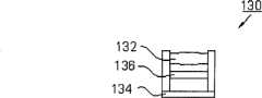
参考图2a,传统的视频电话所用的照相模块130包含透镜单元132以及图像传感器134,例如CMOS或CCD。透镜单元132可由单一透镜或两个透镜所组成,可将来自外界的图像光线引导至图像传感器134上,图像传感器134再将其转换成电子信号。为了滤除不必要的红外光,在透镜单元132和图像传感器134之间,设置有红外截止滤光片(IR cut filter)136。Referring to FIG. 2a, a
参考图2b,一般的主照相模块140包含由三片镜片所组成的三片镜片组142以及图像传感器144。同样地,镜片组142用于将来自外界的图像光线引导至图像传感器144上,图像传感器144再将其转换成电子信号。在镜片组142及图像传感器144之间,也设有红外截止滤光片146,以将不必要的红外光滤除。Referring to FIG. 2 b , a general
此外,参考图3,市面上还有一种具有可转动照相模块310的照相手机300,使用者可根据需要自行将照相模块310转动至手机300的前侧或背侧。In addition, referring to FIG. 3 , there is also a
上述照相手机100包含有两个照相模块130、140,各个照相模块130、140必须有它自己的图像传感器134、144,否则无法运作,但这将造成成本上的增加。再者,虽然手机300仅使用一个可转动的照相模块310,但这会增加机构设计的难度,而且也有使用上可靠度不足的疑虑。The above-mentioned
有鉴于此,便有必要提出一种可携式电子装置的照相模块,以解决上述问题。In view of this, it is necessary to propose a camera module of a portable electronic device to solve the above problems.
发明内容Contents of the invention
本发明的一个目的在于提供一种可携式电子装置的照相模块,能够通过共享组件来达到减少体积及降低成本的目的。An object of the present invention is to provide a camera module of a portable electronic device, which can reduce volume and cost by sharing components.
在第一实施例中,本发明的可携式电子装置的照相模块包含分光组件,其具有第一光输入端、第二光输入端及光输出端。第二透镜单元位于分光组件的第二光输入端的上游,可将收集到的图像光线引导至分光组件的第二光输入端,分光组件再将其由光输出端输出。图像传感器位于分光组件的光输出端下游,可将从其中射出的图像光线转换成电子信号。此外,反射镜设于分光组件的第一光输入端的上游,在反射镜的上游还设有第一透镜单元。反射镜用于将通过第一透镜单元的图像光线反射至分光组件的第一光输入端。进入分光组件第一光输入端的图像光线会从光输出端输出,并到达图像传感器。第一透镜单元可以是三片镜片组,由两个凸透镜以及设于两者光学路径之间的一个凹透镜所组成。而第二透镜单元可以是单个凸透镜,胶合在分光组件的第二光输入端上;或者是三片镜片组,由两个凸透镜以及设于两者光学路径之间的一个凹透镜所组成。In the first embodiment, the camera module of the portable electronic device of the present invention includes a light splitting component having a first light input end, a second light input end and a light output end. The second lens unit is located upstream of the second light input end of the light splitting assembly, and can guide the collected image light to the second light input end of the light splitting assembly, and the light splitting assembly outputs it from the light output end. The image sensor is located downstream of the light output end of the light splitting component, and can convert the image light emitted therefrom into an electronic signal. In addition, the reflection mirror is arranged upstream of the first light input end of the light splitting assembly, and a first lens unit is also arranged upstream of the reflection mirror. The reflection mirror is used to reflect the image light passing through the first lens unit to the first light input end of the light splitting assembly. The image light entering the first light input end of the light splitting component will be output from the light output end and reach the image sensor. The first lens unit may be a three-piece lens group, which is composed of two convex lenses and a concave lens arranged between the two optical paths. The second lens unit can be a single convex lens glued on the second light input end of the light splitting assembly; or a three-piece lens group consisting of two convex lenses and a concave lens arranged between the two optical paths.
在第二实施例中,本发明的可携式电子装置的照相模块类似第一实施例的照相模块,其差异在于第一实施例的第一透镜单元中位于凹透镜至反射镜之光学路径之间的凸透镜,在第二实施例中移到反射镜的下游至分光组件的第一光输入端的上游之间。In the second embodiment, the camera module of the portable electronic device of the present invention is similar to the camera module of the first embodiment, the difference is that the first lens unit of the first embodiment is located between the optical path from the concave lens to the mirror In the second embodiment, the convex lens is moved between the downstream of the reflector and the upstream of the first light input end of the light splitting assembly.
在第三实施例中,本发明的可携式电子装置的照相模块与第一实施例的照相模块类似,也具有分光组件、图像传感器及反射镜。但在分光组件的光输出端的下游至图像传感器的上游之间,设有凸透镜。在反射镜的上游设有凸透镜;而在反射镜的下游至分光组件之第一光输入端的上游之间,设有凹透镜。In the third embodiment, the camera module of the portable electronic device of the present invention is similar to the camera module in the first embodiment, and also has a light splitting component, an image sensor and a mirror. However, a convex lens is provided between the downstream of the light output end of the light splitting assembly and the upstream of the image sensor. A convex lens is arranged upstream of the reflection mirror; a concave lens is arranged between the downstream of the reflection mirror and the upstream of the first light input end of the light splitting assembly.
本发明的另一个目的在于提供一种可携式电子装置,其壳体前侧设有一个开孔,壳体后侧设有另一个开孔,上述各实施例的照相模块则设于壳体内。当图像光线通过各个开孔入射至照相模块后,最后会到达各照相模块的图像传感器上。图像传感器则将所接收到的图像光线转换成对应的电子信号,并由位在壳体前侧上的显示单元根据电子信号将图像传感器所接收到的图像显示。Another object of the present invention is to provide a portable electronic device, the front side of the housing is provided with an opening, the rear side of the housing is provided with another opening, and the camera module of the above-mentioned embodiments is arranged in the housing . After the image light is incident on the camera module through each opening, it will finally reach the image sensor of each camera module. The image sensor converts the received image light into a corresponding electronic signal, and the display unit on the front side of the casing displays the image received by the image sensor according to the electronic signal.
本发明的照相模块可应用于需要照相功能的可携式电子装置上,以接收来自不同方向的图像光线,并通过共享相同的组件来达到减少照相模块的体积以及降低成本的目的。The camera module of the present invention can be applied to portable electronic devices that require a camera function to receive image light from different directions, and achieve the purpose of reducing the size and cost of the camera module by sharing the same components.
为了让本发明的上述和其它目的、特征和优点能更明显,下文特举本发明实施例,并配合所附图示,作详细说明如下。In order to make the above and other objects, features and advantages of the present invention more apparent, the following specifically cites the embodiments of the present invention, together with the accompanying drawings, for a detailed description as follows.
附图说明Description of drawings
图1为传统的具有两个照相模块的照相手机;Fig. 1 is a traditional camera phone with two camera modules;
图2a为传统照相手机上的第二照相模块;Figure 2a is a second camera module on a conventional camera phone;
图2b为传统照相手机上的主照相模块;Figure 2b is the main camera module on a traditional camera phone;
图3为传统的具有一个可转动的照相模块的照相手机;Fig. 3 is a conventional camera phone with a rotatable camera module;
图4、5、6a与6b为本发明第一实施例不同形式的可携式电子装置的照相模块;4, 5, 6a and 6b are camera modules of different forms of portable electronic devices according to the first embodiment of the present invention;
图7、8、9a与9b为本发明第二实施例不同形式的可携式电子装置的照相模块;7, 8, 9a and 9b are camera modules of different forms of portable electronic devices according to the second embodiment of the present invention;
图10与11为本发明第三实施例不同形式的可携式电子装置的照相模块;10 and 11 are camera modules of different forms of portable electronic devices according to the third embodiment of the present invention;
图12为应用本发明的可携式电子装置的照相模块的手机。FIG. 12 is a mobile phone using the camera module of the portable electronic device of the present invention.
附图标记说明Explanation of reference signs
100 照相手机 110 前侧100
120 背侧 130 照相模块120
132 透镜单元 134 图像传感器132
136 红外截止滤光片 142 三片镜片组136
144 图像传感器 146 红外截止滤光片144
300 照相手机 310 照相模块300
400 照相模块 410 透镜单元400
412 凸透镜 414 凹透镜412 Convex
416 凸透镜 420 分光组件416 Convex
422 光输入端 424 光输入端422
426 光输出端 430 图像传感器426
432 红外截止滤光片 440 图像光线432
450 反射镜 460 透镜单元450
462 凸透镜 464 凹透镜462 Convex
466 凸透镜 470 图像光线466 Convex
500 照相模块 600 照相模块500
612 凸透镜 614 凹透镜612 Convex lens 614 Concave lens
616 凸透镜 664 凹透镜616 Convex
666 凸透镜 700 可携式电子装置666 Convex
710 前侧 712 开孔710
720 后侧 722 开孔720
730 壳体 740 显示单元730
具体实施方式Detailed ways
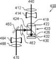
参考图4,本发明第一实施例的可携式电子装置的照相模块400包含分光组件420,例如是立体型分光器(cube-type beam splitter)或平板型分光器(plate-type beam splitter),其具有两个光输入端422、424及一个光输出端426。第二透镜单元410位于分光组件光输入端422的上游,可将接收到的图像光线440引导至分光组件的光输入端422,分光组件420再将其由光输出端426输出。图像传感器430,例如是CCD或CMOS,位于分光组件光输出端426的下游,可将从其中射出的图像光线440转换成对应的电子信号。为滤除不必要的红外光,在分光组件光输出端426的下游以及图像传感器430的上游之间,还设置有红外截止滤光片432。此外,本发明第一实施例的照相模块400还包含反射镜450以及第一透镜单元460。反射镜450位于分光组件420的光输入端424的上游以及第一透镜单元460的下游,以将通过第一透镜单元460的图像光线470反射至分光组件420的光输入端424。进入光输入端424的图像光线470会从光输出端426输出,并到达图像传感器430,接着再转换成另一个对应的电子信号。Referring to FIG. 4, the
上述照相模块400仅包含一个图像传感器430,但利用反射镜450及分光组件420可感测来自不同方向的图像光线。因此,当本发明的照相模块400应用于手机上时,第二透镜单元410可装设于手机前侧,用来当作视讯相机(video camera)模块的光学组件;而第一透镜单元460可装设于手机背侧,可以是一个三片镜片组,由两凸透镜462、466以及设于两者光学路径之间的凹透镜464所组成,用来当作静态照相(still camera)模块的光学组件。以此方式,将减少图像传感器及红外截止滤光片的使用,可降低照相手机的制造成本。The above-mentioned
参考图5,为降低照相模块400的体积,第二透镜单元410可以是单个凸透镜,并可胶合在分光组件420的光输入端422上。此外,参考图6a,第二透镜单元410可为一个三片镜片组,由凸透镜412、416以及设于两者光学路径之间的凹透镜414所组成,用以提高图像的分辨率。另外,凸透镜416可胶合至分光组件420的光输入端422上(见图6b)。由于第二透镜单元410系采用三片镜片,图像的分辨率得以提高,因此其也可作为静态照相模块来使用。上述第二透镜单元410及第一透镜单元460中的凹透镜414、464,用以修正象差(aberration),以提高图像质量。Referring to FIG. 5 , in order to reduce the volume of the
参考图7、8、9a与9b,本发明第二实施例的可携式电子装置的照相模块500,分别类似图4、5、6a与6b中的照相模块400,其差异仅在于照相模块500的凸透镜462设置于反射镜450至分光组件420的光输入端424的光学路径之间。本发明第二实施例的可携式电子装置的照相模块500的凸透镜466与凹透镜464,用以依序接收图像光线470,并将其引导至反射镜450,反射镜450再将图像光线470反射至凸透镜462,凸透镜462再将其引导至分光组件420的光输入端424。Referring to FIGS. 7, 8, 9a and 9b, the
参考图10,本发明第三实施例的可携式电子装置的照相模块600与图4的照相模块400类似,也具有分光组件420、红外截止滤光片432、图像传感器430及反射镜450,但在分光组件420的光输出端426的下游至图像传感器430的上游之间设有凸透镜616。在反射镜450的上游设有凸透镜666;而在反射镜450的下游至分光组件420的光输入端424上游之间设有凹透镜664。当图像光线440由分光组件的光输入端422进入而从光输出端426射出时,凸透镜616会将图像光线440收集并引导至图像传感器430上。此外,图像光线470经由凸透镜666的收集,再经反射镜450的反射而到达分光组件420的光输入端424。由分光组件光输入端424进入的图像光线470将由光输出端426射出,并由凸透镜616引导至图像传感器430上。Referring to FIG. 10, the
上述凸透镜616的作用与第二透镜单元410的作用相同,而凸透镜666、凹透镜664与凸透镜616的共同作用与第一透镜单元460的作用相同,在此不再详述。相较于图4的照相模块400,本实施例的照相模块600减少了一个凸透镜的使用,因此制造成本得以降低,且照相模块的体积也得以减少。The function of the
参考图11,本发明的照相模块600的分光组件420的光输入端422的上游,还可设置凸透镜612以及位于两者光学路径之间的凹透镜614,用于顺次接收图像光线440,并将其引导至分光组件420的光输入端422上,以通过这样提高图像的分辨率。Referring to FIG. 11 , upstream of the
参考图12,本发明的照相模块400、500及600可应用于需要照相和视频功能的可携式电子装置700,例如3G(third generation)手机上。可携式电子装置700包含有壳体730,其前侧710上设有开孔712,后侧720上则设有开孔722,照相模块400、500或600则设于壳体730内(未显示)。图像光线440通过开孔712入射至照相模块400、500或600后,最后会到达各照相模块400、500或600的图像传感器430;而图像光线470通过开孔722入射至照相模块400、500或600后,最后也会到达各照相模块400、500或600的图像传感器430。图像传感器430则将图像光线440、470转换成对应的电子信号,并由位于壳体前侧710上的显示单元740根据电子信号将图像传感器430所接收到的图像显示。应注意的是,在一般情况下,图像光线440与470并不会同时到达图像传感器430。由于照相模块400、500及600内各组件的作用已于前述各实施例中详细说明,在此不再详述。Referring to FIG. 12, the
在不改变原有光路的调制传递函数(Modulation Transfer Function;MTF)的情况下,本发明的照相模块通过共享组件来达到减少体积及降低成本的目的。此外,原先较低分辨率的第二照相模块,也可依照需求增加透镜的数目,通过这样提高第二照相模块的分辨率,使其有更大的利用弹性。Without changing the Modulation Transfer Function (MTF) of the original optical path, the camera module of the present invention achieves the purpose of reducing volume and cost by sharing components. In addition, the number of lenses of the original lower resolution second camera module can also be increased according to the requirement, and the resolution of the second camera module can be increased in this way to make it more flexible to use.
应注意的是,上述各实施例仅是本发明的优选实施形式,本发明主要使用了分光组件420、反射镜450以及图像传感器430,以实现本发明的通过共享组件来达到减少体积及降低成本的目的。也就是反射镜450将图像光线470反射至分光组件420的光输入端424上,再由分光组件420的光输出端426输出,最后到达图像传感器430;而图像光线440则入射至分光组件420的光输入端422,再由分光组件420的光输出端426输出,并到达图像传感器430。It should be noted that the above-mentioned embodiments are only preferred implementation forms of the present invention, and the present invention mainly uses the
虽然本发明已通过上述优选实施例揭示,但上述实施例并非用以限定本发明,任何本领域普通技术人员在不脱离本发明的精神和范围内,可以作各种更动与修改。因此本发明的保护范围应当以所附的权利要求书所界定的范围为准。Although the present invention has been disclosed by the above preferred embodiments, the above embodiments are not intended to limit the present invention, and any person skilled in the art can make various changes and modifications without departing from the spirit and scope of the present invention. Therefore, the protection scope of the present invention should be determined by the scope defined in the appended claims.
Claims (9)
Priority Applications (1)
| Application Number | Priority Date | Filing Date | Title |
|---|---|---|---|
| CN2007101260862ACN101344706B (en) | 2007-07-11 | 2007-07-11 | Portable electronic device and camera module thereof |
Applications Claiming Priority (1)
| Application Number | Priority Date | Filing Date | Title |
|---|---|---|---|
| CN2007101260862ACN101344706B (en) | 2007-07-11 | 2007-07-11 | Portable electronic device and camera module thereof |
Publications (2)
| Publication Number | Publication Date |
|---|---|
| CN101344706A CN101344706A (en) | 2009-01-14 |
| CN101344706Btrue CN101344706B (en) | 2010-09-15 |
Family
ID=40246728
Family Applications (1)
| Application Number | Title | Priority Date | Filing Date |
|---|---|---|---|
| CN2007101260862AActiveCN101344706B (en) | 2007-07-11 | 2007-07-11 | Portable electronic device and camera module thereof |
Country Status (1)
| Country | Link |
|---|---|
| CN (1) | CN101344706B (en) |
Cited By (6)
| Publication number | Priority date | Publication date | Assignee | Title |
|---|---|---|---|---|
| WO2017139600A1 (en)* | 2016-02-12 | 2017-08-17 | Contrast Optical Design & Engineering, Inc. | Systems and methods for hdr video capture with a mobile device |
| US9948829B2 (en) | 2016-02-12 | 2018-04-17 | Contrast, Inc. | Color matching across multiple sensors in an optical system |
| US10554901B2 (en) | 2016-08-09 | 2020-02-04 | Contrast Inc. | Real-time HDR video for vehicle control |
| US10951888B2 (en) | 2018-06-04 | 2021-03-16 | Contrast, Inc. | Compressed high dynamic range video |
| US11265530B2 (en) | 2017-07-10 | 2022-03-01 | Contrast, Inc. | Stereoscopic camera |
| US12309427B2 (en) | 2018-08-14 | 2025-05-20 | Contrast, Inc. | Image compression |
Families Citing this family (7)
| Publication number | Priority date | Publication date | Assignee | Title |
|---|---|---|---|---|
| CN102447836A (en)* | 2009-06-16 | 2012-05-09 | 英特尔公司 | Camera applications in a handheld device |
| TWI434121B (en)* | 2011-05-13 | 2014-04-11 | Quanta Comp Inc | Double direction camera and portable electronic device |
| US8830337B2 (en)* | 2012-09-04 | 2014-09-09 | Himax Imaging Limited | Electronic device with camera functions |
| CN102981350B (en)* | 2012-10-11 | 2015-10-14 | 广东欧珀移动通信有限公司 | A kind of bidirectional imaging device and electronic equipment |
| CN103744255A (en)* | 2013-12-25 | 2014-04-23 | 李东 | Non-linear type optical path camera device |
| US9274311B2 (en)* | 2014-01-13 | 2016-03-01 | Genius Electronic Optical Co., Ltd. | Compact narrow field of view lenses for mobile devices |
| TWI721354B (en)* | 2019-01-07 | 2021-03-11 | 友達光電股份有限公司 | Electronic device and method of switching light receiving direction of which |
Citations (3)
| Publication number | Priority date | Publication date | Assignee | Title |
|---|---|---|---|---|
| GB2368221A (en)* | 2000-08-31 | 2002-04-24 | Lee Scott Friend | Camera apparatus having both omnidirectional and normal view imaging modes. |
| CN1402499A (en)* | 2001-08-16 | 2003-03-12 | 日本电气株式会社 | Portable camera communication terminal with camera |
| US6975358B1 (en)* | 2000-08-31 | 2005-12-13 | Intel Corporation | Dual channel imaging device |
- 2007
- 2007-07-11CNCN2007101260862Apatent/CN101344706B/enactiveActive
Patent Citations (3)
| Publication number | Priority date | Publication date | Assignee | Title |
|---|---|---|---|---|
| GB2368221A (en)* | 2000-08-31 | 2002-04-24 | Lee Scott Friend | Camera apparatus having both omnidirectional and normal view imaging modes. |
| US6975358B1 (en)* | 2000-08-31 | 2005-12-13 | Intel Corporation | Dual channel imaging device |
| CN1402499A (en)* | 2001-08-16 | 2003-03-12 | 日本电气株式会社 | Portable camera communication terminal with camera |
Cited By (21)
| Publication number | Priority date | Publication date | Assignee | Title |
|---|---|---|---|---|
| US10819925B2 (en) | 2016-02-12 | 2020-10-27 | Contrast, Inc. | Devices and methods for high dynamic range imaging with co-planar sensors |
| US11785170B2 (en) | 2016-02-12 | 2023-10-10 | Contrast, Inc. | Combined HDR/LDR video streaming |
| US10200569B2 (en) | 2016-02-12 | 2019-02-05 | Contrast, Inc. | Color matching across multiple sensors in an optical system |
| US10257394B2 (en) | 2016-02-12 | 2019-04-09 | Contrast, Inc. | Combined HDR/LDR video streaming |
| US10257393B2 (en) | 2016-02-12 | 2019-04-09 | Contrast, Inc. | Devices and methods for high dynamic range video |
| US10264196B2 (en) | 2016-02-12 | 2019-04-16 | Contrast, Inc. | Systems and methods for HDR video capture with a mobile device |
| US10536612B2 (en) | 2016-02-12 | 2020-01-14 | Contrast, Inc. | Color matching across multiple sensors in an optical system |
| US12250357B2 (en) | 2016-02-12 | 2025-03-11 | Contrast, Inc. | Combined HDR/LDR video streaming |
| US10742847B2 (en) | 2016-02-12 | 2020-08-11 | Contrast, Inc. | Devices and methods for high dynamic range video |
| US10805505B2 (en) | 2016-02-12 | 2020-10-13 | Contrast, Inc. | Combined HDR/LDR video streaming |
| US9948829B2 (en) | 2016-02-12 | 2018-04-17 | Contrast, Inc. | Color matching across multiple sensors in an optical system |
| US11637974B2 (en) | 2016-02-12 | 2023-04-25 | Contrast, Inc. | Systems and methods for HDR video capture with a mobile device |
| WO2017139600A1 (en)* | 2016-02-12 | 2017-08-17 | Contrast Optical Design & Engineering, Inc. | Systems and methods for hdr video capture with a mobile device |
| US11368604B2 (en) | 2016-02-12 | 2022-06-21 | Contrast, Inc. | Combined HDR/LDR video streaming |
| US11463605B2 (en) | 2016-02-12 | 2022-10-04 | Contrast, Inc. | Devices and methods for high dynamic range video |
| US11910099B2 (en) | 2016-08-09 | 2024-02-20 | Contrast, Inc. | Real-time HDR video for vehicle control |
| US10554901B2 (en) | 2016-08-09 | 2020-02-04 | Contrast Inc. | Real-time HDR video for vehicle control |
| US11265530B2 (en) | 2017-07-10 | 2022-03-01 | Contrast, Inc. | Stereoscopic camera |
| US10951888B2 (en) | 2018-06-04 | 2021-03-16 | Contrast, Inc. | Compressed high dynamic range video |
| US11985316B2 (en) | 2018-06-04 | 2024-05-14 | Contrast, Inc. | Compressed high dynamic range video |
| US12309427B2 (en) | 2018-08-14 | 2025-05-20 | Contrast, Inc. | Image compression |
Also Published As
| Publication number | Publication date |
|---|---|
| CN101344706A (en) | 2009-01-14 |
Similar Documents
| Publication | Publication Date | Title |
|---|---|---|
| CN101344706B (en) | Portable electronic device and camera module thereof | |
| TWI398718B (en) | Portable electronic device and camera module therefor | |
| CN110888216B (en) | Optical lenses, lens modules and terminals | |
| US10701252B2 (en) | Imaging optical system, imaging system, and imaging apparatus | |
| US8830337B2 (en) | Electronic device with camera functions | |
| CN115561881B (en) | Camera module and electronic equipment | |
| JP2004309695A (en) | Imaging optical system and imaging apparatus using imaging optical system | |
| JP2004341013A (en) | Imaging optical system and imaging device using the same | |
| CN114002831A (en) | Optical lens, lens module and terminal | |
| CN112904529A (en) | Optical lens, lens module and electronic equipment | |
| JP2001166209A (en) | Image optical system | |
| CN111830684B (en) | Compact telephoto lens | |
| US20120038749A1 (en) | Stereoscopic camera module and electronic device using the same | |
| KR20070015774A (en) | Lens system for compact camera module and imaging lens with infrared cut-off function | |
| KR102345118B1 (en) | A Camera Module and Portable Terminal having the Same | |
| WO2021143204A1 (en) | Light-splitting flat panel, light-splitting device, light-splitting lens, camera, and electronic device | |
| CN102200675A (en) | Device with lens transition function | |
| CN102116999A (en) | Portable electronic device | |
| JP4197886B2 (en) | Electronic imaging device | |
| CN112243076A (en) | electronic device | |
| CN214480818U (en) | Camera module and electronic device with camera function | |
| CN216057225U (en) | Camera module and terminal equipment | |
| JP2019152850A (en) | Imaging optical system, imaging system and imaging apparatus | |
| KR100853689B1 (en) | Low Light Camera Module Structure | |
| JP2004233536A (en) | Imaging optical system and image pickup unit using the same |
Legal Events
| Date | Code | Title | Description |
|---|---|---|---|
| C06 | Publication | ||
| PB01 | Publication | ||
| C10 | Entry into substantive examination | ||
| SE01 | Entry into force of request for substantive examination | ||
| C14 | Grant of patent or utility model | ||
| GR01 | Patent grant |