CN101344221A - LED lamp strip type street lamp - Google Patents
LED lamp strip type street lampDownload PDFInfo
- Publication number
- CN101344221A CN101344221ACNA2007101680549ACN200710168054ACN101344221ACN 101344221 ACN101344221 ACN 101344221ACN A2007101680549 ACNA2007101680549 ACN A2007101680549ACN 200710168054 ACN200710168054 ACN 200710168054ACN 101344221 ACN101344221 ACN 101344221A
- Authority
- CN
- China
- Prior art keywords
- lamp
- light
- high power
- radiator
- circuit board
- Prior art date
- Legal status (The legal status is an assumption and is not a legal conclusion. Google has not performed a legal analysis and makes no representation as to the accuracy of the status listed.)
- Granted
Links
Images


Classifications
- Y—GENERAL TAGGING OF NEW TECHNOLOGICAL DEVELOPMENTS; GENERAL TAGGING OF CROSS-SECTIONAL TECHNOLOGIES SPANNING OVER SEVERAL SECTIONS OF THE IPC; TECHNICAL SUBJECTS COVERED BY FORMER USPC CROSS-REFERENCE ART COLLECTIONS [XRACs] AND DIGESTS
- Y02—TECHNOLOGIES OR APPLICATIONS FOR MITIGATION OR ADAPTATION AGAINST CLIMATE CHANGE
- Y02B—CLIMATE CHANGE MITIGATION TECHNOLOGIES RELATED TO BUILDINGS, e.g. HOUSING, HOUSE APPLIANCES OR RELATED END-USER APPLICATIONS
- Y02B20/00—Energy efficient lighting technologies, e.g. halogen lamps or gas discharge lamps
- Y02B20/72—Energy efficient lighting technologies, e.g. halogen lamps or gas discharge lamps in street lighting
Landscapes
- Non-Portable Lighting Devices Or Systems Thereof (AREA)
- Arrangement Of Elements, Cooling, Sealing, Or The Like Of Lighting Devices (AREA)
- Fastening Of Light Sources Or Lamp Holders (AREA)
Abstract
Translated fromChinese
Description
Translated fromChinese所属技术领域Technical field
本发明系关于一种发光装置,尤指一种可应用于室外之灯杆上作为路灯,或其它照明或造景用途的发光二极管灯条式路灯设计。The present invention relates to a light emitting device, in particular to a light emitting diode strip type street light design that can be applied to an outdoor light pole as a street light, or for other lighting or landscaping purposes.
背景技术Background technique
目前应用于如路灯之类的发光装置概有利用灯泡或高功率发光二极管等发光组件作为发光源等二种型式,其中灯泡式发光装置因灯泡的耗电量高、光衰大、故障率高及灯泡更换频率高等缺点,故目前发光装置朝向低耗电量、光衰小及故障率较低的发光二极管式发光装置发展。At present, there are two types of light-emitting devices used in street lamps, such as light bulbs or high-power light-emitting diodes, etc. And the disadvantages such as high frequency of bulb replacement, so the current light-emitting device is developing towards the light-emitting diode type light-emitting device with low power consumption, low light decay and low failure rate.
目前习知应用于路灯之类的发光二极管路灯之设计,如图15所示,其主要系采取类似光盘之组成构造设计,亦即习知发光二极管路灯系将复数个高功率发光二极管模块(40)逐一焊接于一铝质电路板(41)上,电性连接其线路,再令铝质电路板(41)连接于一具有大型散热片的散热灯座(42)上,以便把高功率发光二极管模块(40)点亮产生的热,经由该铝质电路板(41)传导至该具有大型散热片的散热灯座(42)上,另于该高功率发光二极管模块(40)前端装设一灯罩(43),该发光二极管路灯组设于路灯的灯杆顶端,提供夜间道路照明之用途。At present, the design of LED street lamps used in street lamps is known, as shown in Figure 15, which mainly adopts a composition structure design similar to that of an optical disc, that is, the conventional LED street lamps are a plurality of high-power LED modules (40 ) are welded to an aluminum circuit board (41) one by one, and the circuit is electrically connected, and then the aluminum circuit board (41) is connected to a heat dissipation lamp holder (42) with a large heat sink, so as to emit high-power light The heat generated by the lighting of the diode module (40) is conducted through the aluminum circuit board (41) to the heat dissipation lamp holder (42) with large heat sinks, and is installed at the front end of the high-power light-emitting diode module (40). A lampshade (43), the light-emitting diode street lamp set is arranged on the top of the lamp pole of the street lamp, and provides the purpose of road lighting at night.
惟前揭发光二极管路灯之使用,虽可提供亮光作为路灯等照明用途,然而,该发光二极管路灯在实际使用过程中存在有以下诸多缺点:However, the use of LED street lamps disclosed above can provide bright light as street lamps and other lighting purposes. However, the LED street lamps have the following disadvantages in actual use:
1.维修不便:习知发光二极管路灯中之复数发光二极管组件系逐一焊接于铝质电路板上,除组装施工上非常麻烦不便,而且当该发光二极管路灯组设于路灯等灯具中使用时,倘若其中有任一高功率发光二极管模块故障或损坏时,一般水电工根本无法自行使用焊枪等工具将损坏的高功率发光二极管模块自电路板上焊下,重新再焊接新的发光二极管组件,因维修拆换困难之故,通常须由专业人员将整个光盘拆下,整组送回原制造厂商维修,或是作整组光盘更换,有维修成本高之缺点。1. Inconvenient maintenance: In conventional LED street lamps, multiple LED components are soldered to the aluminum circuit board one by one, which is very troublesome and inconvenient in assembly and construction, and when the LED street lamp is used in street lamps and other lamps, If any of the high-power LED modules fails or is damaged, general plumbers cannot use tools such as welding torches to solder the damaged high-power LED modules off the circuit board and re-solder new LED components. Due to the difficulty in maintenance and replacement, professionals usually have to disassemble the entire disc and send the entire set back to the original manufacturer for repair, or replace the entire set of discs, which has the disadvantage of high maintenance costs.
2.散热性能不佳:习知之发光二极管路灯中,其所使用之高功率发光二极管模块于工作时会产生高温,由于一发光二极管路灯须装设复数发光二极管组件方能提供足够的光源,因该些发光二极管组件系一同焊设于该铝质电路板汇集传导至共同散热体之灯具座上,因热流加乘效果,且基于发光二极管路灯的重量不宜过重,体积不宜过大等限制下,使得散热灯具座的散热面积有限,故在散热机构设计不良的状态下,造成该发光二极管路灯的散热效果不佳,易使部分发光二极管组件因散热路径差产生的高温而易于烧毁、缩短使用寿命,且连同该铝质电路板上的电子组件也受高温而影响其工作效能,缩短该些电子组件的使用寿命。2. Poor heat dissipation performance: In the conventional LED street lamps, the high-power LED modules used in them will generate high temperature during operation. Since an LED street lamp must be installed with multiple LED components to provide sufficient light source, therefore These LED components are welded together on the aluminum circuit board and conducted to the lamp holder of the common radiator. Due to the effect of heat flow multiplication, and based on the weight of the LED street lamp should not be too heavy, the volume should not be too large and other restrictions. , so that the heat dissipation area of the heat dissipation lamp holder is limited, so in the state of poor design of the heat dissipation mechanism, the heat dissipation effect of the LED street lamp is not good, and it is easy to cause some LED components to be easily burned due to the high temperature generated by the poor heat dissipation path, shortening the use Life, and the electronic components on the aluminum circuit board are also affected by high temperature to affect their working performance, shortening the service life of these electronic components.
3.配光曲线设计困难:一般高功率发光二极管发出之光形为圆形,导致习知发光二极管路灯所发出之光形也近似圆形,但一般路灯所需求之配光曲线为长条式的椭圆形,以满足道路照明之需要,若要将习知发光二极管路灯配光曲线达到长条式的椭圆形,其铝质电路板与大型散热灯座都要随之改变,因应各种配光曲线之需求将会有各种不同之铝质电路板与大型散热灯座,如此会造成庞大之模具与制造成本之浪费,因此习知发光二极管路灯不易作为各种配光曲线的变化设计。3. It is difficult to design the light distribution curve: the light shape emitted by general high-power light-emitting diodes is circular, so the light shape emitted by conventional light-emitting diode street lights is also similar to a circle, but the light distribution curve required by general street lights is long. oval shape to meet the needs of road lighting. If the light distribution curve of conventional LED street lamps is to be elongated oval shape, the aluminum circuit board and the large heat dissipation lamp holder must be changed accordingly. The demand for light curves will require various aluminum circuit boards and large heat-dissipating lamp holders, which will result in a huge waste of molds and manufacturing costs. Therefore, it is not easy to design various light distribution curves for conventional LED street lights.
发明内容Contents of the invention
本发明之主要目的在于提供一种发光二极管灯条式路灯,希藉此设计,克服习知发光二极管路灯维修不便、散热效果不佳及光形不易设计等缺点。The main purpose of the present invention is to provide a light-emitting diode strip-type street light, hoping to overcome the disadvantages of conventional light-emitting diode street lights such as inconvenient maintenance, poor heat dissipation effect and difficult light shape design.
为达成前揭目的,本发明所设计之发光二极管灯条式路灯系包括:In order to achieve the purpose disclosed above, the light-emitting diode lamp strip street lamp designed by the present invention includes:
一灯具座,系一板形座体;以及A lamp holder, which is a plate-shaped holder; and
数组主照明灯条,所述之主照明灯条系包括一散热体、一电路板设于该散热体中,该些主照明灯条各具有数个高功率发光二极管模块电性连接该电路板,该些主照明灯条系以该散热体可拆组地分布组设于该灯具座上,使该高功率发光二极管模块可对外投光。An array of main lighting strips. The main lighting strips include a radiator and a circuit board disposed in the radiator. Each of the main lighting strips has several high-power LED modules electrically connected to the circuit board. The main lighting strips are disassembled and assembled on the lamp holder, so that the high-power light-emitting diode module can project light to the outside.
本发明藉由发光二极管灯条式路灯设计,其特点至少包括有:The present invention is designed by the light-emitting diode strip type street lamp, and its characteristics include at least:
1.维修简便:本发明之发光二极管灯条式路灯系于一灯具座上装设数组独立的主照明灯条,该些主照明灯条与灯具座为可拆组之结构,藉此模块化之设计,使其重量轻、易安装及节省成本,且在维修方面,该些主照明灯条中之任一发光二体组件故障时,维修人员可快速而简便地将故障的发光二极管组件予以更换,具有极佳之维修简便性。1. Easy maintenance: The LED strip light street lamp of the present invention is equipped with a set of independent main lighting strips on a lamp holder. The design makes it light in weight, easy to install and cost-saving, and in terms of maintenance, when any LED component in these main lighting strips fails, the maintenance personnel can quickly and easily replace the faulty LED component , with excellent ease of maintenance.
2.独立的散热机制:各主照明灯条具有独立的散热机制,散热效果佳:本发明所设计之主照明灯条,因每一主照明灯条本身各具有一散热体,藉由该散热体将组设其中的高功率发光二极管模块点亮所产生的热向外散热,使每一主照明灯条各具有独立的散热机制,克服习知发光二极管路灯需要藉由外部散热机制来排除发光二极管组件所产生的之热,进而避免该发光二极管组件因高温而烧毁,具有较长的使用寿命,且因各主照明灯条各具有独立的散热机制,在灯具的设计上,不须特别考虑散热的问题。2. Independent heat dissipation mechanism: each main lighting strip has an independent heat dissipation mechanism, and the heat dissipation effect is good: the main lighting strip designed in the present invention, because each main lighting strip itself has a heat sink, through the heat dissipation The body dissipates the heat generated by lighting the high-power LED modules assembled therein, so that each main lighting strip has an independent heat dissipation mechanism, which overcomes the conventional LED street lights that need to use an external heat dissipation mechanism to eliminate light emission The heat generated by the diode components can prevent the LED components from being burned due to high temperature, and has a long service life, and because each main lighting strip has an independent heat dissipation mechanism, no special consideration is required in the design of the lamp The problem of heat dissipation.
本发明之次一目的系进一步令该发光二极管灯条式路灯具有配光曲线设计容易之功用,其中系令该灯具座之座体为一板体弯折成形的立体构件,该座体具有一平板部,以及至少一斜板部成形于该平板部侧端,所述之斜板部相对于该平板部呈一倾斜角度,该些主照明灯条分布组设于该平板部及斜板上,该些主照明灯条各具有数个高功率发光二极管模块,于该灯具座上呈矩阵状排列,且搭配该灯具座之角度设计,使其可依该灯具照明之设计上的需要,令其照明面积可以均匀及广角化,且配合矩阵排列的投光光点设计,于点亮时具有新颖科技的视觉效果;另一方面,该灯具可依配光曲线简易地透过该灯具座座体之斜板部角度变更,即能轻易设计出长条式的椭圆形之光形,以满足道路照明之需要。The second object of the present invention is to further make the light-emitting diode strip type street lamp have the function of easy light distribution curve design, wherein the base of the lamp holder is a three-dimensional member formed by bending a plate, and the base has a A flat plate portion and at least one slanted plate portion are formed on the side end of the flat plate portion. The slanted plate portion is at an angle of inclination relative to the flat plate portion. The main lighting strips are distributed and assembled on the flat plate portion and the inclined plate. , each of these main lighting strips has several high-power LED modules, which are arranged in a matrix on the lamp holder, and matched with the angle design of the lamp holder, so that it can meet the lighting design requirements of the lamp, so that Its lighting area can be uniform and wide-angle, and with the matrix-arranged light spot design, it has a novel and technological visual effect when lit; on the other hand, the lamp can easily pass through the lamp base according to the light distribution curve Changing the angle of the sloping plate of the body can easily design a long oval light shape to meet the needs of road lighting.
本发明之再一目的系进一步令该发光二极管灯条式路灯中,进一步包括至少一景观灯条设于该灯具座上,使该发光二极管灯条式路灯除可整合该灯具座之数主照明灯条,应用于路灯中作为灯具,使其除具有基本的照明功能外,更进一步结合景观灯条,兼具都市造景之夜间市区景观美化效果。Another object of the present invention is to further make the LED light strip street lamp further include at least one landscape light bar on the lamp holder, so that the LED light strip street lamp can integrate the main lighting of the lamp holder The light bar is used as a lamp in the street lamp, so that it not only has the basic lighting function, but also further combines the landscape light bar, and has the effect of beautifying the urban landscape at night in urban landscaping.
本发明之又一目的系进一步令本发明景观灯条中之高功率发光二极管模块为全彩型高功率发光二极管模块,并使该电路板可利用市电之交流电源频率取样电路来取得交流电源频率,并以此交流电源频率作为时间计算的基准,来进行发光二极管景观灯条之同步控制,令在同一区域内之发光二极管景观灯条一起点亮变色时,可以长时间维持同步变色之效果。Another object of the present invention is to further make the high-power LED module in the landscape light bar of the present invention a full-color high-power LED module, and make the circuit board obtain AC power by using the AC power frequency sampling circuit of the mains Frequency, and use the AC power frequency as the basis for time calculation to carry out synchronous control of LED landscape light strips, so that when the LED landscape light strips in the same area light up and change color together, the effect of synchronous color change can be maintained for a long time .
附图说明Description of drawings
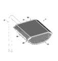
图1系本发明发光二极管灯条式路灯之一较佳实施例设于路灯灯杆上的立体示意图。FIG. 1 is a three-dimensional schematic diagram of a preferred embodiment of a light-emitting diode strip-type street light of the present invention installed on a street light pole.
图2系本发明发光二极管灯条式路灯增设景观灯条之另一较佳实施例设于路灯灯杆上的立体示意图。Fig. 2 is a three-dimensional schematic view of another preferred embodiment of adding a landscape light bar to the LED strip-type street lamp of the present invention installed on the street lamp pole.
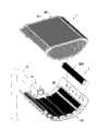
图3系本发明图2所示较佳实施例之局部分解示意图。Fig. 3 is a partially exploded schematic view of the preferred embodiment shown in Fig. 2 of the present invention.
图4系本发明发光二极管灯条式路灯各较佳实施例中主照明灯条之立体分解示意图。Fig. 4 is a three-dimensional exploded schematic view of the main lighting strip in each preferred embodiment of the LED strip-type street lamp of the present invention.
图5系本发明发光二极管灯条式路灯各较佳实施例中主照明灯条另一较佳实施例之立体分解示意图。Fig. 5 is a three-dimensional exploded schematic diagram of another preferred embodiment of the main lighting strip in each preferred embodiment of the LED strip-type street lamp of the present invention.
图6系第二、三图所示发光二极管灯条式路灯较佳实施例中景观灯条之立体分解示意图。Fig. 6 is a three-dimensional exploded schematic view of the landscape light bar in the preferred embodiment of the LED light bar type street light shown in the second and third figures.
图7系第六图所示景观灯条较佳实施例之部分电路之方块图。Fig. 7 is a block diagram of some circuits of a preferred embodiment of the landscape light bar shown in Fig. 6 .
图8系图2所示发光二极管灯条式路灯较佳实施例组设于路灯灯杆上之仰视立体示意图。Fig. 8 is a perspective view from above of a preferred embodiment of the LED light bar type street light shown in Fig. 2 assembled on the street light pole.
图9系图2所示发光二极管灯条式路灯较佳实施例组设于路灯灯杆上之整体仰视立体示意图。Fig. 9 is an overall perspective view from above of a preferred embodiment of the light-emitting diode strip type street lamp shown in Fig. 2 assembled on a street lamp pole.
图10系图2所示发光二极管灯条式路灯较佳实施例之投光示意图。Fig. 10 is a schematic diagram of the light projection of a preferred embodiment of the LED light bar type street lamp shown in Fig. 2 .
图11系本发明发光二极管灯条式路灯增设景观灯条及灯罩之一较佳实施例之立体分解示意图。Fig. 11 is a three-dimensional exploded schematic diagram of a preferred embodiment of adding a landscape light bar and a lampshade to the LED strip-type street lamp of the present invention.
图12系第十一图所示发光二极管灯条式路灯较佳实施例组合后之立体示意图。Fig. 12 is a three-dimensional schematic diagram of a preferred embodiment of the light-emitting diode strip type street lamp shown in Fig. 11 after assembly.
图13系本发明发光二极管灯条式路灯增设相同于主照明灯条之景观灯条及灯罩之另一较佳实施例之立体分解示意图。Fig. 13 is a three-dimensional exploded schematic view of another preferred embodiment of adding a landscape light bar and a lampshade that are the same as the main lighting light bar to the LED light bar type street lamp of the present invention.
图14系第十图所示发光二极管灯条式路灯较佳实施例组合后之立体示意图。Fig. 14 is a three-dimensional schematic diagram of a preferred embodiment of the light-emitting diode strip type street lamp shown in Fig. 10 after assembly.
图15系习知发光二极管路灯之立体分解示意图。Fig. 15 is a three-dimensional exploded schematic diagram of a conventional LED street lamp.
主要组件符号说明Explanation of main component symbols
(1)发光二极管灯条式路灯(1) LED strip street lights
(2)灯杆 (3)灯杆固定座(2) Light pole (3) Light pole fixing seat
(10)灯具座 (11)平板部(10) Lamp holder (11) Flat panel
(12)斜板部 (13)纵板部(12) Inclined plate part (13) Longitudinal plate part
(131)连接部(131) Connecting part
(20)主照明灯条(20) Main lighting strip
(21)散热体 (211)组接板(21) Radiator (211) Assembly plate
(212)容置区 (213)散热鳍片(212) Accommodating area (213) Radiating fins
(214)贯穿孔(214) Through hole
(22)电路板 (221)连接器(22) Circuit board (221) Connector
(222)端子座(222) Terminal block
(23)高功率发光二极管模块(23) High Power LED Module
(231)接脚(231) Pins
(24)侧盖 (241)防水垫圈(24) Side cover (241) Waterproof gasket
(25)反光灯罩 (26)透光体(25) Reflective lampshade (26) Translucent body
(28)导线(28) Wire
(30)景观灯条 (30A)景观灯条(30)Landscape light bar (30A)Landscape light bar
(31)导光体(31) Light guide
(32)端盖 (321)嵌合槽(32) End cap (321) Fitting groove
(33)高功率发光二极管模块(33) High Power LED Module
(331)模块固定座 (34)控制电路板(331)Module holder (34)Control circuit board
(341)连接器(341)Connector
(35)交流电源频率取样电路(35) AC power frequency sampling circuit
(351)光耦合器 (352)整流二极管(351) Optocoupler (352) Rectifier Diode
(353)限流电阻 (354)输出电阻(353) Current limiting resistor (354) Output resistor
(36)控制电路 (37)防水垫圈(36) Control circuit (37) Waterproof gasket
(38)防水接头 (39)导线(38) Waterproof connector (39) Wire
(40)高功率发光二极管模块(40) High Power LED Modules
(41)铝质电路板 (42)散热灯座(41) Aluminum circuit board (42) Heat sink lamp holder
(43)灯罩(43) Lamp shade
(50)灯罩 (51)散热孔(50) Lampshade (51) Cooling hole
具体实施方式Detailed ways
如图1、2、11、13所示,系揭示本发明发光二极管灯条式路灯之数种具体可行的较佳实施例,由图中可以见及,该发光二极管灯条式路灯(1)系包括一灯具座(10)以及数组主照明灯条(20),或如第二、十一、十三图所示者,进一步包括至少一景观灯条(30)、(30A),或如图12、13所示者,再进一步包括一灯罩(50),其中:As shown in Figures 1, 2, 11, and 13, it discloses several specific and feasible preferred embodiments of the LED strip street lamp of the present invention. It can be seen from the figure that the LED strip street lamp (1) It includes a lamp holder (10) and an array of main lighting strips (20), or as shown in the second, eleventh, and thirteenth figures, and further includes at least one landscape light strip (30), (30A), or as shown in Those shown in Figures 12 and 13 further comprise a lampshade (50), wherein:
如图1-3所示,该灯具座(10)系包括一板形的座体,该座体可为一平面板体,或为一板体弯折成形的立体构件,该板体弯折成形之座体具有一平板部(11),以及至少一斜板部(12)系成形于该平板部(11)侧端,所述之斜板部(12)相对于该平板部(11)具有一倾斜角度,该斜板部(12)可为倾斜之平面状,或为弯弧之弧曲斜面状等设计,该灯具座(10)之平板部(11)、斜板部(12)上各设有数穿孔,用以分别提供主照明灯条(20)组设其上。As shown in Figures 1-3, the lamp holder (10) includes a plate-shaped seat body, which can be a flat plate body, or a three-dimensional member formed by bending a plate body, and the plate body is bent and formed The seat body has a flat plate portion (11), and at least one inclined plate portion (12) is formed on the side end of the flat plate portion (11), and the described inclined plate portion (12) has a An angle of inclination, the slant plate portion (12) can be designed as an inclined plane, or as an arc-curved inclined surface, etc., the flat plate portion (11) and the slant plate portion (12) of the lamp holder (10) Each is provided with several perforations for providing main lighting strips (20) to be assembled on it.
如图1所示之较佳实施例,该灯具座(10)之座体系于其平板部(11)相对应两侧各设数斜板部(12)自该平板部(11)侧边接续弯折倾斜,每一侧接续弯折成形的数斜板部(12)相对于该平板部(11)之倾斜角度依序渐增;如第二、三图所示之较佳实施例,该灯具座(10)之座体更进一步于两侧最外侧斜板部(12)末端接续一延伸之纵板部(13),该二纵板部(13)上设置二连接部(131)间隔相对,于该二连接部(131)间形成一朝上的凹形口,分别提供一景观灯条(30)组设其中。In the preferred embodiment shown in Figure 1, the seat system of the lamp holder (10) is provided with several sloping plate parts (12) on the corresponding two sides of the flat part (11) and continues from the side of the flat part (11). Bending and tilting, the inclination angles of the number of slant plate parts (12) that are bent and formed on each side gradually increase relative to the flat plate part (11); as in the preferred embodiment shown in the second and third figures, the The seat body of the lamp holder (10) is further connected with an extended vertical plate portion (13) at the end of the outermost sloping plate portion (12) on both sides, and two connecting portions (131) are arranged on the two vertical plate portions (13) In contrast, an upward concave opening is formed between the two connecting parts (131), and a landscape light bar (30) is respectively provided and assembled therein.
如图4所示,该些主照明灯条(20)各包括一散热体(21)、一电路板(22)以及至少一高功率发光二极管模块(23),该散热体(21)系为导热性材料制成的长条中空构件,其包括一组接板(211)设于该散热体(21)出光面、一容置区(212)位于该散热体(21)内侧,以及数散热鳍片(213)成形于该散热体(21)外侧面,该电路板(22)系设于该散热体(21)之容置区(212)内,所述的高功率发光二极管模块(23)为一组内含高功率发光二极管的组件,该高功率发光二极管模块(23)上设有一组接脚(231),可拆组地装设于该电路板(22)的连接器(221)上,该高功率发光二极管模块(23)之发光端可通过该散热体(21)之组接板(211)外,该些主照明灯条(20)系以其散热体(21)之组接板(211)分布组设于该灯具座(10)上,该高功率发光二极管模块(23)所发射的光可通过该灯具座(10)对外投光。As shown in Figure 4, these main lighting strips (20) each include a radiator (21), a circuit board (22) and at least one high-power LED module (23), and the radiator (21) is A long hollow member made of thermally conductive material, which includes a set of connecting plates (211) arranged on the light-emitting surface of the heat sink (21), an accommodating area (212) located inside the heat sink (21), and several heat sinks. Fins (213) are formed on the outer surface of the radiator (21), the circuit board (22) is arranged in the accommodation area (212) of the radiator (21), and the high-power light-emitting diode module (23 ) is a set of components containing high-power light-emitting diodes. The high-power light-emitting diode module (23) is provided with a set of pins (231), which are detachably mounted on the connector (221) of the circuit board (22). ), the light-emitting end of the high-power light-emitting diode module (23) can pass through the assembly plate (211) of the heat sink (21), and the main lighting strips (20) are connected by the heat sink (21) The assembly plate (211) is distributed and assembled on the lamp holder (10), and the light emitted by the high-power light-emitting diode module (23) can be projected to the outside through the lamp holder (10).
前述之主照明灯条(20)之散热体(21)可使用导热材料挤制成的构件,该组接板(211)一体成形于该散热体(21)出光面,该散热体(21)两端连通容置区(212)的开口处各设一侧盖(24)配合防水垫圈(241)作防水性密封,该电路板(22)其上设有至少一端子座(222),并外接之导线(28)穿过一侧盖(24)外,用以外接电源;该散热体(21)出光面之组接板(211)上设有相对于高功率发光二极管模块(23)数量的贯穿孔(214),提供该些高功率发光二极管模块(23)抵贴组设于该组接板(211)上,其接脚(231)通过该贯穿孔(214)插接于电路板(22)上相对应的连接器(221)上电性连接,并使该些高功率发光二极管模块(23)点亮时产生的热可直接热传导至该散热体(21)上散热。The radiator (21) of the aforementioned main lighting strip (20) can be extruded from a thermally conductive material. Both ends are connected to the opening of the accommodation area (212) and each side cover (24) is provided with a waterproof gasket (241) for waterproof sealing. The circuit board (22) is provided with at least one terminal block (222), and The external wire (28) passes through the side cover (24) for external power supply; the assembly plate (211) of the light-emitting surface of the radiator (21) is provided with a number corresponding to the number of high-power light-emitting diode modules (23). The through hole (214) provides these high-power LED modules (23) to be assembled on the assembly board (211), and its pins (231) are plugged into the circuit board through the through hole (214) The corresponding connectors (221) on the (22) are electrically connected, and the heat generated when these high-power light-emitting diode modules (23) are lit can be directly thermally conducted to the radiator (21) for heat dissipation.
如图4所示,前述之主照明灯条(20)尚可进一步于每一高功率发光二极管模块(23)之出光端装设一反光灯罩(25),并于该反光灯罩(25)前端装设一透光体(26),且该透光体(26)可选自平面镜、凸透镜与凹透镜中的一种,可根据每一高功率发光二极管模块(23)点亮时的发光角度,来决定使用平面镜、凸透镜与凹透镜,该反光灯罩(25)可固接于该散热体(21)之组接板(211)上。As shown in Figure 4, the aforementioned main lighting strip (20) can be further equipped with a reflector lampshade (25) at the light-emitting end of each high-power LED module (23), and at the front end of the reflector lampshade (25) A light-transmitting body (26) is installed, and the light-transmitting body (26) can be selected from one of a plane mirror, a convex lens and a concave lens, and can be lighted according to the light-emitting angle of each high-power light-emitting diode module (23), To determine the use of plane mirrors, convex lenses and concave lenses, the reflective lampshade (25) can be fixed on the assembly plate (211) of the radiator (21).
如图5所示之另一较佳实施例,该些主照明灯条(20)各包括一散热体(21)、一电路板(22)以及至少一高功率发光二极管模块(23),该散热体(21)系为导热性材料制成之长条构件,该散热体(21)外周面形成数散热鳍片(213),该散热体(21)中形成一具有开口之容置区(212),于该容置区(212)开口处装设一可拆组的组接板(211),该组接板(211)上设有至少一贯穿孔(214),该散热体(21)两端连通容置区(212)的开口处各设一侧盖(24)配合防水垫圈(241)作防水性密封;该电路板(22)可为具有导热性之电路板(如铝质电路板…等),该电路板(22)系设于该散热体(21)之容置区(212)内,其上设有至少一端子座(222),并外连接一导线(28)伸出散热体(21)之一侧盖(24)外,所述的高功率发光二极管模块(23)为一组内含高功率发光二极管的组件,其底面具有数接点,使该高功率发光二极管模块(23)可透过表面粘着技术焊接于该电路板(22)上,每一高功率发光二极管模块(23)之出光端尚可进一步装设一反光灯罩(25),该反光灯罩(25)前端亦可再装设一透光体(26),且该透光体(26)可选自平面镜、凸透镜与凹透镜中的一种用以提高每一高功率发光二极管模块(23)点亮时的发光角度,来决定使用平面镜、凸透镜与凹透镜,所述之高功率发光二极管模块(23)之发光端可通过该组接板(211)之贯穿孔(214)对外投光。Another preferred embodiment shown in Figure 5, these main lighting strips (20) each include a radiator (21), a circuit board (22) and at least one high-power light-emitting diode module (23), the The heat sink (21) is a strip member made of thermally conductive material. Several cooling fins (213) are formed on the outer peripheral surface of the heat sink (21), and an accommodating area with an opening is formed in the heat sink (21). 212), a detachable assembly plate (211) is installed at the opening of the accommodation area (212), the assembly plate (211) is provided with at least one through hole (214), and the radiator (21) Both ends are connected to the opening of the accommodation area (212) and are respectively provided with a side cover (24) to cooperate with a waterproof gasket (241) to make a waterproof seal; the circuit board (22) can be a circuit board with thermal conductivity (such as an aluminum circuit board... etc.), the circuit board (22) is set in the accommodation area (212) of the heat sink (21), and at least one terminal block (222) is arranged on it, and a wire (28) is connected to the outside to extend Out of one side cover (24) of the radiator (21), the high-power light-emitting diode module (23) is a group of components containing high-power light-emitting diodes, and its bottom surface has digital contacts, so that the high-power light-emitting diodes The module (23) can be welded on the circuit board (22) through surface-mounting technology, and a light-emitting end of each high-power light-emitting diode module (23) can be further equipped with a reflector lampshade (25), and the reflector lampshade (25 ) front end can also be equipped with a light-transmitting body (26), and the light-transmitting body (26) can be selected from a kind of plane mirror, convex lens and concave lens in order to improve the lighting of each high-power light-emitting diode module (23). The light-emitting angle at the time determines the use of plane mirrors, convex lenses and concave lenses. The light-emitting end of the high-power light-emitting diode module (23) can project light through the through hole (214) of the assembly plate (211).
该景观灯条(30)(30A)可为灯条式发光模块、或为相同于如前揭主照明灯条(20)的发光模块、或为其它型式的发光模块,其中如图6所示之较佳实施例系揭示该景观灯条(30)采用灯条式发光模块设计,其主要包括一导光体(31)、一高功率发光二极管模块(33)、一控制电路板(34)以及二端盖(32),该导光体(31)系可透光材料(如压克力…等)成形的对象,其形状可为直条棒状体、或为条状体成形之其它几何形状,该导光体(31)内可掺入散射体,且该散射体可选自气泡、光丝、扩散剂及扩散粉中的一种;该高功率发光二极管模块(33)为一组内含至少一高功率发光二极管组件之模块,使该高功率发光二极管模块(33)可为可发出特定波长之单色型发光二极管模块、或为全彩型发光二极管模块,其中该高功率发光二极管模块(33)为全彩型高功率发光二极管模块时,其包含有数颗可发出不同波长的发光二极管组件,使其可受控变化发出不同的色光,该高功率发光二极管模块(33)可直接设于该导光体(31)一端,或藉由一模块固定座(331)设置于导光体(31)一端,使该高功率发光二极管模块(33)之发光端朝向导光体(31)之端部,该控制电路板(34)系设于该高功率发光二极管模块(33)的背部电性连接,该控制电路板(34)且外接导线,用以外接电源,该高功率发光二极管模块(33)具有一组接脚,该控制电路板(34)上设有连接器(341),提供该高功率发光二极管模块(33)以其接脚插设于该连接器(341)上,电性连接该控制电路板(34),该二端盖(32)系分别组接于该导光体(31)两端,其一端盖(32)系结合防水垫圈(37)组接该导光体(31)之一端部,且将该高功率发光二极管模块(33)及控制电路板(34)罩盖于内,该控制电路板(34)外接之导线(39)穿过该端盖(32)或进一步套设一防水接头(38)作为防水性密封,该二端盖(32)与该导光体(31)端部间可藉由套接、螺接或其它组接手段组合,于本较佳实施例中,系揭示该二端盖(32)以螺接方式组接于该棒状导光体(31)两端,该二端盖(32)之外端部尚可形成一嵌合槽(321),使该景观灯条(30)组设于该灯具座(10)两侧纵板部(13)二连接部(131)间,可以该嵌合槽(321)与该连接部(131)嵌接组合,使该景观灯条(30)固定该灯具座(10)之纵板部(13)上。The landscape light bar (30) (30A) can be a light bar type light-emitting module, or a light-emitting module that is the same as the main light bar (20) disclosed above, or a light-emitting module of other types, as shown in Figure 6 The preferred embodiment discloses that the landscape light bar (30) adopts a light bar-type light-emitting module design, which mainly includes a light guide (31), a high-power light-emitting diode module (33), a control circuit board (34) And two end caps (32), the light guide (31) is an object that can be shaped by light-transmitting materials (such as acrylic... etc.), and its shape can be a straight rod-shaped body, or other geometric shapes formed by a strip-shaped body shape, the light guide body (31) can be mixed with a scatterer, and the scatterer can be selected from one of bubbles, light filaments, diffusion agents and diffusion powders; the high-power light-emitting diode module (33) is a set of A module containing at least one high-power light-emitting diode component, so that the high-power light-emitting diode module (33) can be a monochromatic light-emitting diode module that can emit a specific wavelength, or a full-color light-emitting diode module, wherein the high-power light-emitting diode module When the diode module (33) is a full-color high-power light-emitting diode module, it includes several light-emitting diode components that can emit different wavelengths, so that it can be controlled to change and emit different colors. The high-power light-emitting diode module (33) can be Set directly at one end of the light guide body (31), or arrange at one end of the light guide body (31) through a module fixing seat (331), so that the light-emitting end of the high-power light-emitting diode module (33) faces the light guide body ( 31), the control circuit board (34) is electrically connected to the back of the high-power light-emitting diode module (33), and the control circuit board (34) is connected with an external wire for external power supply. The light-emitting diode module (33) has a group of pins, and the control circuit board (34) is provided with a connector (341), and the high-power light-emitting diode module (33) is provided with its pins plugged into the connector (341). ), which is electrically connected to the control circuit board (34), the two end caps (32) are respectively assembled at both ends of the light guide (31), and one end cap (32) is combined with a waterproof gasket (37) Connect to one end of the light guide (31), and cover the high-power light-emitting diode module (33) and the control circuit board (34) inside, and the wire (39) connected externally to the control circuit board (34) passes through The end cap (32) may be further sleeved with a waterproof joint (38) as a waterproof seal, and the two end caps (32) and the end of the light guide body (31) can be connected by sockets, screws or other combinations. The combination of connecting means, in this preferred embodiment, discloses that the two end caps (32) are assembled at both ends of the rod-shaped light guide (31) in a screw connection mode, and the outer ends of the two end caps (32) A fitting groove (321) can still be formed, so that the landscape light bar (30) is assembled between the two connecting parts (131) of the longitudinal plate parts (13) on both sides of the lamp holder (10), and the fitting groove ( 321) is embedded and combined with the connecting portion (131), so that the landscape light bar (30) is fixed on the vertical plate portion (13) of the lamp holder (10).
如图13、14所示,系揭示该景观灯条(30A)其组成构造大致上相同于前揭主照明灯条(20)的发光模块,亦即该景观灯条(30A)系包括一散热体、一控制电路板设于该散热体中,以及数个全彩型高功率发光二极管模块设于该散热体中并电性连接该控制电路板,该景观灯条系以该散热体可拆组地组设于该灯具座(10)上,该些高功率发光二极管模块可对外投光。该景观灯条(30A)使用之高功率发光二极管模块为全彩型高功率发光二极管模块,亦即包含有数颗可发出不同波长的发光二极管组件,使其可受控变化发出不同的色光。As shown in Figures 13 and 14, it is disclosed that the composition and structure of the landscape light bar (30A) is substantially the same as that of the light-emitting module of the main lighting light bar (20) exposed before, that is, the landscape light bar (30A) includes a heat dissipation Body, a control circuit board is set in the heat sink, and several full-color high-power LED modules are set in the heat sink and electrically connected to the control circuit board, the landscape light bar is detachable by the heat sink Groups are arranged on the lamp holder (10), and these high-power light-emitting diode modules can project light to the outside. The high-power LED module used in the landscape light bar (30A) is a full-color high-power LED module, that is, it contains several LED components that can emit different wavelengths, so that it can be controlled to change and emit different colors.
前述之景观灯条(30)、(30A)中之高功率发光二极管模块(33)为全彩型高功率发光二极管模块时,该景观灯条(30)所使用之控制电路板(34)之部分电路,如图7所示,其包括有:When the high-power light-emitting diode module (33) in the aforementioned landscape light bar (30), (30A) is a full-color high-power light-emitting diode module, the control circuit board (34) used in the landscape light bar (30) Part of the circuit, as shown in Figure 7, includes:
一交流电源频率取样电路(35),其输入端系连接市电之交流电源,以取出该交流电源之频率,并于其输出端送出相对应该之连续脉波;An AC power frequency sampling circuit (35), the input end of which is connected to the AC power source of the mains, to extract the frequency of the AC power source, and send corresponding continuous pulse waves at its output end;
一控制电路(36),系内建有多组变化模式,该控制电路(36)一输入端系连接前述交流电源频率取样电路(35)以接收该连续脉波,并藉此脉波得与交流电源频率同步,并根据变化模式产生一控制信号,控制高功率发光二极管模块之复数发光二极管组件之明灭与颜色变化。A control circuit (36) has many groups of change modes built in, and an input end of the control circuit (36) is connected to the aforementioned AC power frequency sampling circuit (35) to receive the continuous pulse wave, and the pulse wave can be compared with The frequency of the AC power supply is synchronized, and a control signal is generated according to the change mode to control the light-off and color changes of the multiple LED components of the high-power LED module.
前述交流电源频率取样电路(35)主要是以一光耦合器(351)构成,该光耦合器(351)内部的发光二极管系与一整流二极管(352)及一限流电阻(353)串联,输入的交流电源系经过该整流二极管(352)及限流电阻(353)整流后成为半波波形,该光耦合器(351)之发光二极管系由该整流后的电源驱动;又该光耦合器(351)内部的光敏晶体管系连接于一输出电阻(354)与接地之间,该输出电阻(354)的另一端系连接该直流电源。当前述光耦合器(351)内部的发光二极管由整流后的半波弦波驱动点亮时,系可驱动光敏晶体管导通,藉由光敏晶体管交替地导通/截止,于输出电阻(354)上系可产生一周期性的连续脉波。The aforementioned AC power frequency sampling circuit (35) is mainly composed of an optocoupler (351), and the light emitting diode inside the optocoupler (351) is connected in series with a rectifier diode (352) and a current limiting resistor (353). The input AC power system becomes a half-wave waveform after being rectified by the rectifier diode (352) and the current limiting resistor (353), and the light-emitting diode of the optocoupler (351) is driven by the rectified power supply; and the optocoupler The photosensitive transistor inside (351) is connected between an output resistor (354) and the ground, and the other end of the output resistor (354) is connected to the DC power supply. When the light-emitting diode inside the optocoupler (351) is driven by the rectified half-wave sine wave to light up, it can drive the phototransistor to be turned on, and the phototransistor is turned on/off alternately, and the output resistor (354) The upper line can produce a periodic continuous pulse wave.
藉此,该景观灯条(30)外接上市电之交流电源时,因每个地区之市电频率均相同(例如为50HZ或60HZ),所以利用此市电之交流电源频率作为该景观灯条之同步信号,以便让景观灯条(30)达到同步变色之效果。In this way, when the landscape light bar (30) is externally connected to the AC power of the commercial power, since the frequency of the commercial power in each region is the same (for example, 50HZ or 60HZ), the frequency of the AC power of the city power is used as the landscape light bar synchronous signal, so that the landscape light bar (30) can achieve the effect of synchronous color change.
如图11至14所示,系揭示本发明发光二极管灯条式路灯(1)进一步包括一灯罩(50)之较佳实施例,所述之灯罩(50)系罩设于该灯具座(10)上,并藉由卡扣、螺丝锁固或其它等固接手段组设定位,将该些主照明灯条(20)或进一步包括景观灯条(30)(30a)罩盖于内,藉以增加该路灯(1)的美观性。As shown in Figures 11 to 14, it is disclosed that the light-emitting diode lamp strip street lamp (1) of the present invention further includes a preferred embodiment of a lampshade (50), and the described lampshade (50) is set on the lamp holder (10) ), and set the position by means of buckle, screw locking or other fastening means, cover these main lighting strips (20) or further include landscape lighting strips (30) (30a), In order to increase the aesthetics of the street lamp (1).
前述之灯罩(50)可为金属板一体成形,或如图11至14所示之各较佳实施例,该灯罩(50)为金属板组合而成,并与该灯具座(10)之形状相匹配,其中为使该灯罩(50)进一步具有良好的散热性,该灯罩(50)上更设有复数个散热孔(51),以便于该些主照明灯条(20)、景观灯条(30)(30A)产生的高热散发之用。The aforementioned lampshade (50) can be formed integrally with a metal plate, or the preferred embodiments shown in Figures 11 to 14. In order to make the lampshade (50) further have good heat dissipation, a plurality of cooling holes (51) are further provided on the lampshade (50), so that these main lighting strips (20), landscape lighting strips (30) (30A) for high heat dissipation.
本发明藉由该发光二极管灯条式路灯(1)设计,于使用时,以应用于路灯为例,如图8至9所示,该发光二极管灯条式路灯(1)可利用其灯具座(10)直接组设于一灯杆(2)上端,或以该灯具座(10)结合一灯杆固定座(3)配合螺丝组设于于一灯杆(2)上端,其次,再令该些主照明灯条(20)以及景观灯条(30)(30A)的导线插入该灯杆(2)内连接电源,组成一路灯,当该发光二极管灯条式路灯(1)点亮时,设于该灯具座(10)上之数主照明灯条(20)各以其高功率发光二极管模块(23)发光。The present invention uses the design of the light-emitting diode strip-type street lamp (1). When in use, it is applied to a street lamp as an example. As shown in Figures 8 to 9, the light-emitting diode strip-type street lamp (1) can use its lamp holder (10) directly assemble on the upper end of a light pole (2), or combine the lamp holder (10) with a light pole fixing seat (3) to cooperate with the screw group and set on the upper end of a light pole (2), and then make The lead wires of these main lighting strips (20) and landscape light strips (30) (30A) are inserted into the light pole (2) to connect to the power supply to form a road light. When the light emitting diode strip type street light (1) lights , the number of main lighting strips (20) that are located on the lamp holder (10) each emit light with its high-power light-emitting diode module (23).
如图10所示来说明其配光角度之设计,其中藉由该灯具座(10)上位于平板部(11)主要照射范围为灯具之正下方,两侧相邻平板部(11)之斜板部(12)主要照射范围为路灯正下方之两侧,另一个角度更倾斜之斜板部(12)其照射范围为路灯下方之外围两侧,使该些高功率发光二极管模块(23)向下投光之照射范围具有均匀且其光形为长条式的椭圆形,以满足道路照明之需要,同时利用该些高功率发光二极管模块(23)于该灯具座(10)上呈矩阵状排列之投光光点设计,使该发光二极管灯条式路灯(1)点亮时可呈现新颖科技的视觉效果。As shown in Figure 10 to illustrate the design of its light distribution angle, the main irradiation range of the lamp holder (10) located on the flat part (11) is directly below the lamp, and the oblique angles of the adjacent flat parts (11) on both sides The main irradiating range of the plate part (12) is the two sides directly below the street lamp, and the sloping plate part (12) with a more inclined angle has its irradiating range on both sides of the periphery below the street lamp, so that these high-power light-emitting diode modules (23) The irradiation range of the downward projection light is uniform and its light shape is a long ellipse to meet the needs of road lighting. At the same time, these high-power light-emitting diode modules (23) are used to form a matrix on the lamp holder (10) The design of projecting light spots arranged in a shape enables the light-emitting diode strip street lamp (1) to present a novel and technological visual effect when it is lit.
此外,当街道旁整列路灯上所装设之发光二极管灯条式路灯(1)附加有该景观灯条(30)时,该些景观灯条(30)可藉由该高功率发光二极管模块(33)对导光体(31)投射特定波长的色光,或利用全彩型高功率发光二极管模块配合电路控制,进而利用市电之交流电源频率作为该景观灯条之同步信号,以便让每一组景观灯条(30)产生同步变色之效果,作为街道景观造景之用,创造都市美学。In addition, when the landscape light strips (30) are attached to the light-emitting diode strip-type street lights (1) installed on the street lights beside the street, these landscape light strips (30) can be powered by the high-power light-emitting diode module ( 33) Project color light of a specific wavelength to the light guide (31), or use a full-color high-power light-emitting diode module to cooperate with circuit control, and then use the AC power frequency of the mains as the synchronization signal of the landscape light bar, so that each The set of landscape light bars (30) produces the effect of synchronous color change, which is used as streetscape landscaping to create urban aesthetics.
由上述可知,本发明相较于传统灯泡型路灯有低耗电量、光衰小、故障率较低及景观照明之优点,相较于习知发光二极管路灯有维修简便、独立的散热机制、配光曲线容易设计及景观照明之优点、系确实具有产业利用性、新颖性及进步性等专利要件,爰依法具文提出申请。From the above, it can be known that compared with the traditional bulb-type street lamp, the present invention has the advantages of low power consumption, low light decay, low failure rate and landscape lighting. Compared with the conventional LED street lamp, it has the advantages of easy maintenance, independent heat dissipation mechanism, The light distribution curve is easy to design and the advantages of landscape lighting, and it really has the patent elements such as industrial applicability, novelty and progress, so it is necessary to file an application in accordance with the law.
本发明所附图式仅提供参考与说明用,并非用来对本发明加以限制者。故举凡运用本发明专利说明书及图标内容所为之等效结构变化,均同理包含于本发明之范围内,合予陈明。The accompanying drawings of the present invention are provided for reference and illustration only, and are not intended to limit the present invention. Therefore, all equivalent structural changes made by using the contents of the patent specification and diagrams of the present invention are equally included in the scope of the present invention and are hereby declared.
Claims (19)
Priority Applications (1)
| Application Number | Priority Date | Filing Date | Title |
|---|---|---|---|
| CN2007101680549ACN101344221B (en) | 2007-10-29 | 2007-10-29 | LED lamp strip type street lamp |
Applications Claiming Priority (1)
| Application Number | Priority Date | Filing Date | Title |
|---|---|---|---|
| CN2007101680549ACN101344221B (en) | 2007-10-29 | 2007-10-29 | LED lamp strip type street lamp |
Publications (2)
| Publication Number | Publication Date |
|---|---|
| CN101344221Atrue CN101344221A (en) | 2009-01-14 |
| CN101344221B CN101344221B (en) | 2010-09-29 |
Family
ID=40246282
Family Applications (1)
| Application Number | Title | Priority Date | Filing Date |
|---|---|---|---|
| CN2007101680549AExpired - Fee RelatedCN101344221B (en) | 2007-10-29 | 2007-10-29 | LED lamp strip type street lamp |
Country Status (1)
| Country | Link |
|---|---|
| CN (1) | CN101344221B (en) |
Cited By (19)
| Publication number | Priority date | Publication date | Assignee | Title |
|---|---|---|---|---|
| CN101761839A (en)* | 2009-05-14 | 2010-06-30 | 浙江西子光电科技有限公司 | Light-emitting diode (LED) illuminating device with easy assembly and disassembly |
| CN101900263A (en)* | 2009-06-01 | 2010-12-01 | 彭云滔 | Combined high-power LED lamp |
| WO2010139179A1 (en)* | 2009-06-01 | 2010-12-09 | Peng Yuntao | Combined high-power led lamp |
| CN101915381A (en)* | 2010-08-20 | 2010-12-15 | 河南光之源太阳能科技有限公司 | High-power LED street lamp |
| WO2012037710A1 (en)* | 2010-09-21 | 2012-03-29 | Wang Yi | Led street lamp |
| CN102454918A (en)* | 2010-10-20 | 2012-05-16 | 富准精密工业(深圳)有限公司 | Light-emitting diode (LED) lamp |
| CN102454919A (en)* | 2010-10-20 | 2012-05-16 | 富准精密工业(深圳)有限公司 | LED lamp |
| CN102454916A (en)* | 2010-10-20 | 2012-05-16 | 富准精密工业(深圳)有限公司 | LED lamps |
| CN102086984B (en)* | 2009-12-04 | 2012-10-17 | 富士迈半导体精密工业(上海)有限公司 | LED lamps |
| CN101881383B (en)* | 2009-05-08 | 2013-01-23 | 安提亚科技股份有限公司 | Fresnel-style LED light bar lamps |
| CN103134023A (en)* | 2011-12-01 | 2013-06-05 | 海洋王照明科技股份有限公司 | Lamp |
| WO2013102373A1 (en)* | 2012-01-06 | 2013-07-11 | 胜方光电科技股份有限公司 | Modularized street lamp |
| CN103511880A (en)* | 2012-06-25 | 2014-01-15 | 隆达电子股份有限公司 | Light emitting diode lighting device |
| CN103528034A (en)* | 2013-10-23 | 2014-01-22 | 中微光电子(潍坊)有限公司 | LED street lamp light source module, manufacturing method thereof and cooling device thereof |
| CN107909932A (en)* | 2015-03-23 | 2018-04-13 | 深圳市雷迪奥视觉技术有限公司 | A kind of embedded high-power lamp LED display |
| CN110553228A (en)* | 2018-05-15 | 2019-12-10 | 四季洋圃生物机电股份有限公司 | Light emitting diode lamp holder |
| CN110566918A (en)* | 2019-10-12 | 2019-12-13 | 佛山市顺德区胜鸿塑料制品有限公司 | High-performance waterproof rack for LED lamp |
| CN106537026B (en)* | 2014-09-02 | 2020-09-08 | 索尼公司 | Bulb-type light source device and light guide member |
| WO2021121073A1 (en)* | 2019-12-18 | 2021-06-24 | 深圳市中光工业技术研究院 | Beam lamp light source system |
Family Cites Families (2)
| Publication number | Priority date | Publication date | Assignee | Title |
|---|---|---|---|---|
| CN1594962A (en)* | 2003-10-29 | 2005-03-16 | 陈海生 | LED lamp |
| CN200961806Y (en)* | 2006-10-22 | 2007-10-17 | 佛山市顺德区裕升光电技术有限公司 | LED road lamp |
- 2007
- 2007-10-29CNCN2007101680549Apatent/CN101344221B/ennot_activeExpired - Fee Related
Cited By (22)
| Publication number | Priority date | Publication date | Assignee | Title |
|---|---|---|---|---|
| CN101881383B (en)* | 2009-05-08 | 2013-01-23 | 安提亚科技股份有限公司 | Fresnel-style LED light bar lamps |
| CN101761839A (en)* | 2009-05-14 | 2010-06-30 | 浙江西子光电科技有限公司 | Light-emitting diode (LED) illuminating device with easy assembly and disassembly |
| CN101900263A (en)* | 2009-06-01 | 2010-12-01 | 彭云滔 | Combined high-power LED lamp |
| WO2010139179A1 (en)* | 2009-06-01 | 2010-12-09 | Peng Yuntao | Combined high-power led lamp |
| CN102086984B (en)* | 2009-12-04 | 2012-10-17 | 富士迈半导体精密工业(上海)有限公司 | LED lamps |
| CN101915381A (en)* | 2010-08-20 | 2010-12-15 | 河南光之源太阳能科技有限公司 | High-power LED street lamp |
| WO2012037710A1 (en)* | 2010-09-21 | 2012-03-29 | Wang Yi | Led street lamp |
| CN102454918A (en)* | 2010-10-20 | 2012-05-16 | 富准精密工业(深圳)有限公司 | Light-emitting diode (LED) lamp |
| CN102454919A (en)* | 2010-10-20 | 2012-05-16 | 富准精密工业(深圳)有限公司 | LED lamp |
| CN102454916A (en)* | 2010-10-20 | 2012-05-16 | 富准精密工业(深圳)有限公司 | LED lamps |
| CN103134023A (en)* | 2011-12-01 | 2013-06-05 | 海洋王照明科技股份有限公司 | Lamp |
| WO2013102373A1 (en)* | 2012-01-06 | 2013-07-11 | 胜方光电科技股份有限公司 | Modularized street lamp |
| GB2513038A (en)* | 2012-01-06 | 2014-10-15 | Amko Solara Lighting Co Ltd | Modularized street lamp |
| CN103511880A (en)* | 2012-06-25 | 2014-01-15 | 隆达电子股份有限公司 | Light emitting diode lighting device |
| CN103511880B (en)* | 2012-06-25 | 2015-11-18 | 隆达电子股份有限公司 | Light emitting diode lighting device |
| CN103528034A (en)* | 2013-10-23 | 2014-01-22 | 中微光电子(潍坊)有限公司 | LED street lamp light source module, manufacturing method thereof and cooling device thereof |
| CN106537026B (en)* | 2014-09-02 | 2020-09-08 | 索尼公司 | Bulb-type light source device and light guide member |
| CN107909932A (en)* | 2015-03-23 | 2018-04-13 | 深圳市雷迪奥视觉技术有限公司 | A kind of embedded high-power lamp LED display |
| CN107909932B (en)* | 2015-03-23 | 2019-11-26 | 深圳市雷迪奥视觉技术有限公司 | A kind of embedded high-power lamp LED display |
| CN110553228A (en)* | 2018-05-15 | 2019-12-10 | 四季洋圃生物机电股份有限公司 | Light emitting diode lamp holder |
| CN110566918A (en)* | 2019-10-12 | 2019-12-13 | 佛山市顺德区胜鸿塑料制品有限公司 | High-performance waterproof rack for LED lamp |
| WO2021121073A1 (en)* | 2019-12-18 | 2021-06-24 | 深圳市中光工业技术研究院 | Beam lamp light source system |
Also Published As
| Publication number | Publication date |
|---|---|
| CN101344221B (en) | 2010-09-29 |
Similar Documents
| Publication | Publication Date | Title |
|---|---|---|
| CN101344221A (en) | LED lamp strip type street lamp | |
| TWI351490B (en) | ||
| CN102165251B (en) | LED lighting device | |
| JP3146628U (en) | Light emitting diode lamp | |
| US7824070B2 (en) | LED lighting fixture | |
| US7654703B2 (en) | Directly viewable luminaire | |
| KR100999162B1 (en) | Lighting device using light emitting diode | |
| US20110156584A1 (en) | Led lighting device | |
| KR100923982B1 (en) | LED fluorescent lamp type fluorescent lamp | |
| US20130107530A1 (en) | High Efficiency LED Lighting System with Thermal Diffusion | |
| KR101278258B1 (en) | Lamp with appearance distinguished from main lighting | |
| KR101406515B1 (en) | LED Lighting Modules | |
| KR100981683B1 (en) | LED lighting equipment | |
| JP6074704B2 (en) | lighting equipment | |
| KR101058901B1 (en) | LED landscape lighting equipment | |
| KR100990424B1 (en) | LED lighting device with angle setting function for light emission direction | |
| KR101150830B1 (en) | a frame for light-instrument with radiation of heat and LED lighting using frame | |
| KR20100025697A (en) | Plate type streetlight device using led | |
| US10907804B2 (en) | Lighting apparatus | |
| JP3156929U (en) | LED lighting equipment | |
| CN101881383B (en) | Fresnel-style LED light bar lamps | |
| KR20120070847A (en) | The illumination module for illumination system based on blue-chip and the illumination system therewith | |
| ES2221560B1 (en) | "LIGHTING MODULE". | |
| TW201033523A (en) | Fresnel-type LED strip-type lamp |
Legal Events
| Date | Code | Title | Description |
|---|---|---|---|
| C06 | Publication | ||
| PB01 | Publication | ||
| C10 | Entry into substantive examination | ||
| SE01 | Entry into force of request for substantive examination | ||
| C14 | Grant of patent or utility model | ||
| GR01 | Patent grant | ||
| CF01 | Termination of patent right due to non-payment of annual fee | Granted publication date:20100929 Termination date:20141029 | |
| EXPY | Termination of patent right or utility model |