CN101342679A - A polishing head for chemical mechanical polishing - Google Patents
A polishing head for chemical mechanical polishingDownload PDFInfo
- Publication number
- CN101342679A CN101342679ACNA2008101187043ACN200810118704ACN101342679ACN 101342679 ACN101342679 ACN 101342679ACN A2008101187043 ACNA2008101187043 ACN A2008101187043ACN 200810118704 ACN200810118704 ACN 200810118704ACN 101342679 ACN101342679 ACN 101342679A
- Authority
- CN
- China
- Prior art keywords
- retaining ring
- mechanical polishing
- chamber
- barrier film
- rubbing head
- Prior art date
- Legal status (The legal status is an assumption and is not a legal conclusion. Google has not performed a legal analysis and makes no representation as to the accuracy of the status listed.)
- Pending
Links
Images


Landscapes
- Mechanical Treatment Of Semiconductor (AREA)
- Finish Polishing, Edge Sharpening, And Grinding By Specific Grinding Devices (AREA)
Abstract
Translated fromChinese
Description
Translated fromChinese技术领域technical field
本发明涉及集成电路制造技术领域,特别是涉及一种用于化学机械抛光的抛光头。The invention relates to the technical field of integrated circuit manufacturing, in particular to a polishing head for chemical mechanical polishing.
背景技术Background technique
在集成电路的制造过程中,由于特征尺寸的不断缩小和金属互连层数的不断增加,图形曝光的焦深变得越来越小。要实现多层布线,晶圆表面必须具有很高的均匀性,而CMP(Chemical-MechanicalPolish,化学机械抛光)技术是目前最有效的全局平坦化技术。In the manufacturing process of integrated circuits, due to the continuous reduction of feature size and the continuous increase of the number of metal interconnection layers, the depth of focus of pattern exposure becomes smaller and smaller. To realize multi-layer wiring, the surface of the wafer must have high uniformity, and CMP (Chemical-Mechanical Polish, chemical mechanical polishing) technology is currently the most effective global planarization technology.
CMP技术是将待抛光的晶圆由抛光头夹持,并将其以一定压力压在抛光垫上,在抛光过程中,抛光头带动晶圆沿转轴旋转,抛光垫则沿另一转轴旋转,由磨粒和化学溶液组成的抛光液在晶圆和抛光垫之间流动,通过化学和机械的共同作用实现表面平坦化。在抛光过程中,抛光头起着夹持晶圆并对其背侧施加下压力(downforce)的作用,是实现表面平坦化的关键所在。CMP technology is to hold the wafer to be polished by the polishing head and press it on the polishing pad with a certain pressure. During the polishing process, the polishing head drives the wafer to rotate along the rotation axis, and the polishing pad rotates along the other rotation axis. The polishing liquid composed of abrasive grains and chemical solution flows between the wafer and the polishing pad, and the surface is planarized through the joint action of chemical and mechanical. During the polishing process, the polishing head plays the role of clamping the wafer and exerting a downforce on its backside, which is the key to achieving surface planarization.
在现有的CMP技术中,已知有多种原因可以引起晶圆表面的非均匀性。这些原因包括:施加到晶圆背侧的下压力不均匀、因抛光垫在晶圆边缘区域和在中心区域出现的典型作用差异而引起的边缘效应、金属/氧化层的非均匀沉积等。迄今为止,为同时解决这些问题所做的努力尚没有取得成功。In the existing CMP technology, it is known that there are various reasons that can cause the non-uniformity of the wafer surface. These reasons include: non-uniform down force applied to the backside of the wafer, edge effects due to the typical difference in the action of the polishing pad at the edge and center of the wafer, non-uniform deposition of the metal/oxide layer, etc. Efforts to address these issues simultaneously have so far been unsuccessful.
与此同时,随着特征尺寸的不断缩小,为了降低RC(阻容)延迟,铜互连和低k材料的引入已成为必然。而低k材料的多孔结构使得其机械性能变得很差,CMP过程中的常规下压力(2.0-6.0psi)已无法满足要求,必须采用低下压力(<2.0psi),这就需要对抛光头进行相应的改进。At the same time, with the continuous shrinking of the feature size, in order to reduce the RC (resistance capacitance) delay, the introduction of copper interconnection and low-k materials has become inevitable. However, the porous structure of low-k materials makes its mechanical properties very poor. The conventional downforce (2.0-6.0psi) in the CMP process can no longer meet the requirements, and low downforce (<2.0psi) must be used, which requires the polishing head Make corresponding improvements.
发明内容Contents of the invention
本发明实施例要解决的问题是提供一种用于化学机械抛光的抛光头,以实现在抛光过程中获得较好的均匀性。The problem to be solved by the embodiments of the present invention is to provide a polishing head for chemical mechanical polishing, so as to achieve better uniformity in the polishing process.
为达到上述目的,本发明实施例的技术方案提供一种用于化学机械抛光的抛光头,所述抛光头包括:In order to achieve the above object, the technical solution of the embodiment of the present invention provides a polishing head for chemical mechanical polishing, the polishing head includes:
基座,所述基座下方边缘区域有环状凹槽;a base with an annular groove in the lower edge area of the base;
保持环隔膜,固定在所述基座的下方,与所述环状凹槽形成保持环腔室;The retaining ring diaphragm is fixed under the base and forms a retaining ring chamber with the annular groove;
保持环,通过所述保持环隔膜浮动于所述保持环腔室的下方,所述保持环在所述基座的正下方设置有口袋区域,用来容纳晶圆;a retaining ring floating below the retaining ring chamber through the retaining ring diaphragm, and the retaining ring is provided with a pocket area directly below the base for accommodating wafers;
多腔室隔膜,所述多腔室隔膜有盘状平面,其上集成有多个同心环状肋,所述盘状平面、同心环状肋与所述基座的下表面形成多个相互独立的同心环状腔室。A multi-chamber diaphragm, the multi-chamber diaphragm has a disc-shaped plane on which a plurality of concentric annular ribs are integrated, and the disc-shaped plane, concentric annular ribs and the lower surface of the base form a plurality of mutually independent concentric annular chambers.
其中,所述保持环腔室容纳有气体或液体,所述气体或液体的压力通过所述保持环隔膜传递至所述保持环,形成下压力。Wherein, the retaining ring chamber contains gas or liquid, and the pressure of the gas or liquid is transmitted to the retaining ring through the retaining ring diaphragm to form a downward force.
其中,所述多个相互独立的同心环状腔室容纳有气体或液体,所述气体或液体的压力通过所述多腔室隔膜传递至晶圆,形成下压力。Wherein, the multiple independent concentric annular chambers contain gas or liquid, and the pressure of the gas or liquid is transmitted to the wafer through the multi-chamber diaphragm to form a downward force.
其中,所述保持环腔室内的气体或液体的压力是可以调节的。Wherein, the pressure of the gas or liquid in the retaining ring chamber can be adjusted.
其中,所述多个相互独立的同心环状腔室内的气体或液体的压力可以分别调节。Wherein, the pressure of the gas or liquid in the plurality of mutually independent concentric annular chambers can be adjusted separately.
其中,所述同心环状肋的末端有垂直于所述同心环状肋的环状平板,用于与所述基座固定。Wherein, the end of the concentric annular rib has an annular flat plate perpendicular to the concentric annular rib for fixing with the base.
其中,所述多个相互独立的同心环状腔室为3-5个。Wherein, the plurality of mutually independent concentric annular chambers is 3-5.
其中,所述保持环隔膜和多腔室隔膜的材料为弹性材料,所述弹性材料包括氟橡胶、硅橡胶或聚氨酯橡胶。Wherein, the materials of the retaining ring diaphragm and the multi-chamber diaphragm are elastic materials, and the elastic materials include fluorine rubber, silicon rubber or polyurethane rubber.
其中,所述保持环隔膜与所述基座的固定方式和所述多腔室隔膜与所述基座的固定方式,为采用粘贴和/或机械连接的方式。Wherein, the fixing method of the retaining ring diaphragm and the base and the fixing method of the multi-chamber diaphragm and the base are pasting and/or mechanical connection.
其中,所述保持环的下部有多个沿径向打通、均匀分布的凹槽,所述凹槽用于在抛光过程中液体及磨削的排入/排出通道。Wherein, the lower part of the retaining ring has a plurality of radially opened and uniformly distributed grooves, and the grooves are used for liquid and grinding discharge in/out channels during the polishing process.
与现有技术相比,本发明的技术方案具有如下优点:Compared with the prior art, the technical solution of the present invention has the following advantages:
本发明实施例在抛光过程中,该抛光头可以根据多腔室隔膜调节作用在晶圆上不同区域的下压力,可以根据保持环隔膜调节作用在保持环上的下压力,同时多腔室隔膜和保持环隔膜的设计可实现低下压力抛光,因此能够改善晶圆表面的平坦化效果。In the embodiment of the present invention, during the polishing process, the polishing head can adjust the downforce acting on different regions on the wafer according to the multi-chamber diaphragm, and can adjust the downforce acting on the retaining ring according to the retaining ring diaphragm, while the multi-chamber diaphragm The design of the diaphragm and retaining ring enables low downforce polishing, thereby improving planarization of the wafer surface.
附图说明Description of drawings
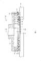
图1是本发明实施例的一种抛光头的剖面结构示意图;Fig. 1 is the cross-sectional structure schematic diagram of a kind of polishing head of the embodiment of the present invention;
图2是本发明实施例的一种抛光头的另一剖面结构示意图;Fig. 2 is another sectional structural schematic diagram of a kind of polishing head of the embodiment of the present invention;
图3是本发明实施例的一种保持环的剖面结构示意图;Fig. 3 is a schematic cross-sectional structure diagram of a retaining ring according to an embodiment of the present invention;
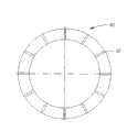
图4是本发明实施例的一种保持环的仰视示意图;Fig. 4 is a schematic bottom view of a retaining ring according to an embodiment of the present invention;
图5是本发明实施例的一种多腔室隔膜的剖面结构示意图;5 is a schematic cross-sectional structure diagram of a multi-chamber diaphragm according to an embodiment of the present invention;
图6是本发明实施例的一种多腔室隔膜的俯视示意图。Fig. 6 is a schematic top view of a multi-chamber membrane according to an embodiment of the present invention.
具体实施方式Detailed ways
下面结合附图和实施例,对本发明的具体实施方式作进一步详细描述。以下实施例用于说明本发明,但不用来限制本发明的范围。The specific implementation manners of the present invention will be further described in detail below in conjunction with the accompanying drawings and embodiments. The following examples are used to illustrate the present invention, but are not intended to limit the scope of the present invention.
图1和图2是根据本发明优选实施例的抛光头100的剖面结构示意图。抛光头100包括一上壳体10、一基座20、一保持环隔膜30、一保持环40以及一多腔室隔膜50。1 and 2 are schematic cross-sectional structural views of a
上壳体10可与一驱动轴相连接,并在抛光过程中以驱动轴带动晶圆200沿轴线90朝一固定方向旋转。驱动轴在抛光过程中与抛光垫300呈垂直状态。上壳体10呈圆柱形状,其外径对于200mm规格的晶圆约为250mm,对于300mm规格的晶圆则约为350mm。此外,有通孔穿过上壳体10,用以气体或液体管路穿过,以便用气压或液压控制抛光头100对晶圆200施加下压力。考虑到其结构特点及工况环境,上壳体10应选用强度高、韧性好、耐腐蚀的材料,如304#钢、316#钢、钛酸铝陶瓷等。The
基座20呈圆柱形状,其外径与上壳体10相一致。其上有用以形成保持环腔室的环状凹槽。基座20上与上壳体10相连接,下与保持环40及多腔室隔膜50相连接。基座20同样应选用强度高、韧性好、耐腐蚀的材料。The
保持环隔膜30是一环状薄膜,其完全覆盖在基座20的环状凹槽上,并利用钳制环74、75固定,从而形成保持环腔室66。保持环隔膜30通过钳制环74、75采用粘贴或机械连接或二者并用的方式固定。考虑到其结构特点及工况环境,保持环隔膜30的材料应为氟橡胶、硅橡胶或聚氨酯橡胶等弹性材料,厚度为0.2-3mm。The
保持环40为一环状平板,其通过某种方式与保持环隔膜30连接,并经由保持环隔膜30浮动于保持环腔室66的下方,从而在基座20的正下方定义出一口袋区域,其大小恰好用来容纳晶圆200。在抛光过程中,保持环40的内环表面咬合晶圆200,以避免晶圆200从抛光头100底部滑出。在抛光过程中,保持环40直接与抛光垫200接触,其磨损、腐蚀情况非常严重,因此保持环40应选用强度高、弹性好、耐磨损、耐腐蚀、温差变形小的材料,PPS(Polyphenylene Sulfide聚苯硫醚)、PEEK(Poly Ether Ether Ketone,聚醚醚酮)等工程塑料为其较佳选择。The
见图3和图4,保持环40的上部有一环状台阶41,保持环40通过环状台阶41的上表面与保持环隔膜30固定,从而保证了保持环40有足够的浮动空间。保持环40的下部有多个沿径向打通、均匀分布的凹槽42,凹槽42用作在抛光过程中液体及磨削的排入/排出通道。凹槽42的深度在2-5mm之间,数量在6-12个之间为宜。3 and 4, there is an
回到图1和图2,多腔室隔膜50呈圆盘状,其上集成有多个同心环状肋。多腔室隔膜50与基座20的下表面一起形成了多个相互独立的同心环状腔室61、62、63、64、65。在抛光过程中,多腔室隔膜50的下表面与晶圆200的背侧接触,并通过多个相互独立的同心环状腔室61、62、63、64、65对晶圆背侧施加气体或液体压力,形成下压力。对于200mm规格的晶圆,同心环状腔室以3个为佳,对于300mm规格的晶圆,同心环状腔室以5个为佳。该优选实施例中的同心环状腔室为5个。Referring back to FIG. 1 and FIG. 2 , the
见图5和图6,多腔室隔膜50的圆盘状平面上集成有5个同心环状肋51、52、53、54、55,这些同心环状肋的末端分别有一个垂直于该同心环状肋的环状平板51a、52a、53a、54a、55a。通过这些环状平板及钳制环71、72、73,多腔室隔膜50采用粘贴或机械连接或二者并用的方式固定在基座20上,形成多个相互独立的同心环状腔室61、62、63、64、65。考虑到其结构特点及工况环境,多腔室隔膜50的材料应为氟橡胶、硅橡胶或聚氨酯橡胶等弹性材料,厚度为0.2-3mm。See Fig. 5 and Fig. 6, five concentric
回到图1和图2,根据本发明的优选实施例,基座20上开有61a、62a、63a、64a、65a、66a等通孔,用于向同心环状腔室61、62、63、64、65及保持环腔室66中通入气体或液体,从而对晶圆200和保持环40施加下压力。改变通入气体量或液体量的大小即可改变不同腔室的压力大小,进而可以改变施加在晶圆200上相应区域和保持环40上的压力大小。Returning to Fig. 1 and Fig. 2, according to the preferred embodiment of the present invention, the
前面提到,影响晶圆表面非均匀性的主要因素之一是金属/氧化层的非均匀沉积导致晶圆表面出现的高低落差。而本抛光头的多腔室设计能够对晶圆背侧的不同区域施加不同的压力,也就是说,对高的区域施加大一点的压力,这样抛光速率会更快,对低的区域施加小一些的压力,这样抛光速率会慢一些,如此以来就能够消除金属/氧化层的非均匀沉积导致的高低落差,使抛光后的晶圆表面达到较佳的均匀性。之所以把多腔室设计呈同心环状分布,是因为前道工序-金属/氧化层的沉积一般采用旋涂等方式进行,这些工艺形成的高低落差往往呈同心环状分布。As mentioned earlier, one of the main factors affecting the non-uniformity of the wafer surface is the uneven deposition of the metal/oxide layer resulting in a drop in height on the wafer surface. However, the multi-chamber design of the polishing head can apply different pressures to different areas on the backside of the wafer, that is, apply a little higher pressure to the high area, so that the polishing rate will be faster, and apply less pressure to the low area. Some pressure, so that the polishing rate will be slower, so that the height difference caused by the non-uniform deposition of the metal/oxide layer can be eliminated, so that the polished wafer surface can achieve better uniformity. The reason why the multi-chamber design is distributed in a concentric ring is because the deposition of the metal/oxide layer in the previous process is generally carried out by spin coating, etc., and the height difference formed by these processes is often distributed in a concentric ring.
与此同时,通过改变通入保持环腔室66中气体量或液体量的大小可改变作用在保持环40上的下压力,从而可以调节保持环40对抛光垫300的压缩程度,改善因抛光垫在晶圆边缘区域和在中心区域出现的典型作用差异而引起的边缘效应。At the same time, the downforce acting on the retaining
本发明的抛光头能够改善晶圆边缘的非均匀性;能够调节晶圆表面材料的去除轮廓,以补偿晶圆上的结构层的非均匀沉积;能够实现低下压力抛光,进而能够获得优异的平坦化效果。The polishing head of the present invention can improve the non-uniformity of the wafer edge; can adjust the removal profile of the wafer surface material to compensate for the non-uniform deposition of the structural layer on the wafer; can realize low down pressure polishing, and then can obtain excellent flatness effect.
以上所述仅是本发明的优选实施方式,应当指出,对于本技术领域的普通技术人员来说,在不脱离本发明技术原理的前提下,还可以做出若干改进和润饰,这些改进和润饰也应视为本发明的保护范围。The above is only a preferred embodiment of the present invention, it should be pointed out that for those of ordinary skill in the art, without departing from the technical principle of the present invention, some improvements and modifications can also be made. These improvements and modifications It should also be regarded as the protection scope of the present invention.
Claims (10)
Priority Applications (1)
| Application Number | Priority Date | Filing Date | Title |
|---|---|---|---|
| CNA2008101187043ACN101342679A (en) | 2008-08-19 | 2008-08-19 | A polishing head for chemical mechanical polishing |
Applications Claiming Priority (1)
| Application Number | Priority Date | Filing Date | Title |
|---|---|---|---|
| CNA2008101187043ACN101342679A (en) | 2008-08-19 | 2008-08-19 | A polishing head for chemical mechanical polishing |
Publications (1)
| Publication Number | Publication Date |
|---|---|
| CN101342679Atrue CN101342679A (en) | 2009-01-14 |
Family
ID=40244861
Family Applications (1)
| Application Number | Title | Priority Date | Filing Date |
|---|---|---|---|
| CNA2008101187043APendingCN101342679A (en) | 2008-08-19 | 2008-08-19 | A polishing head for chemical mechanical polishing |
Country Status (1)
| Country | Link |
|---|---|
| CN (1) | CN101342679A (en) |
Cited By (14)
| Publication number | Priority date | Publication date | Assignee | Title |
|---|---|---|---|---|
| CN101780657A (en)* | 2010-03-25 | 2010-07-21 | 南京航空航天大学 | Polishing loading device capable of uniformly distributing load on surface of loader |
| CN102380820A (en)* | 2010-08-31 | 2012-03-21 | 不二越机械工业株式会社 | Polishing apparatus |
| CN104942697A (en)* | 2014-03-24 | 2015-09-30 | 盛美半导体设备(上海)有限公司 | Wafer grinding head and wafer absorbing method |
| CN106887399A (en)* | 2010-12-20 | 2017-06-23 | Ev 集团 E·索尔纳有限责任公司 | Storing apparatus for keeping chip |
| CN106891244A (en)* | 2017-03-01 | 2017-06-27 | 天津华海清科机电科技有限公司 | Rubbing head |
| CN107756232A (en)* | 2017-11-10 | 2018-03-06 | 北京鼎泰芯源科技发展有限公司 | A kind of wafer polishing apparatus |
| CN107953242A (en)* | 2017-12-22 | 2018-04-24 | 北京半导体专用设备研究所(中国电子科技集团公司第四十五研究所) | Color-buffing finish device and polishing system |
| CN109623628A (en)* | 2018-12-12 | 2019-04-16 | 大连理工大学 | Inhibit the method for edge effect in a kind of mechanical lapping or polishing process |
| CN112045548A (en)* | 2020-08-24 | 2020-12-08 | 华海清科股份有限公司 | Wafer bearing device for chemical mechanical polishing and chemical mechanical polishing equipment |
| CN114286736A (en)* | 2019-08-27 | 2022-04-05 | 应用材料公司 | Chemical mechanical polishing correction tool |
| CN115151376A (en)* | 2020-07-08 | 2022-10-04 | 应用材料公司 | Multi-tooth magnetron retaining ring |
| CN115805523A (en)* | 2022-12-29 | 2023-03-17 | 西安奕斯伟材料科技有限公司 | Fixed plate, polishing device and polishing method |
| CN116276624A (en)* | 2023-03-29 | 2023-06-23 | 江苏山水半导体科技有限公司 | Chemical mechanical polishing method for improving PSG removal rate and consistency thereof |
| CN120244827A (en)* | 2025-05-29 | 2025-07-04 | 北京特思迪半导体设备有限公司 | Capsule film, polishing press head, equipment and method for polishing square substrate |
- 2008
- 2008-08-19CNCNA2008101187043Apatent/CN101342679A/enactivePending
Cited By (26)
| Publication number | Priority date | Publication date | Assignee | Title |
|---|---|---|---|---|
| CN101780657B (en)* | 2010-03-25 | 2011-05-11 | 南京航空航天大学 | Polishing loading device capable of uniformly distributing load on surface of loader |
| CN101780657A (en)* | 2010-03-25 | 2010-07-21 | 南京航空航天大学 | Polishing loading device capable of uniformly distributing load on surface of loader |
| CN102380820A (en)* | 2010-08-31 | 2012-03-21 | 不二越机械工业株式会社 | Polishing apparatus |
| CN102380820B (en)* | 2010-08-31 | 2015-07-15 | 不二越机械工业株式会社 | Polishing apparatus |
| CN106887399B (en)* | 2010-12-20 | 2020-02-21 | Ev 集团 E·索尔纳有限责任公司 | Accommodating device for holding wafers |
| CN106887399A (en)* | 2010-12-20 | 2017-06-23 | Ev 集团 E·索尔纳有限责任公司 | Storing apparatus for keeping chip |
| US11756818B2 (en) | 2010-12-20 | 2023-09-12 | Ev Group E. Thallner Gmbh | Accommodating device for retaining wafers |
| US11355374B2 (en) | 2010-12-20 | 2022-06-07 | Ev Group E. Thallner Gmbh | Accommodating device for retaining wafers |
| US10886156B2 (en) | 2010-12-20 | 2021-01-05 | Ev Group E. Thallner Gmbh | Accomodating device for retaining wafers |
| US10325798B2 (en) | 2010-12-20 | 2019-06-18 | Ev Group E. Thallner Gmbh | Accommodating device for retaining wafers |
| CN104942697A (en)* | 2014-03-24 | 2015-09-30 | 盛美半导体设备(上海)有限公司 | Wafer grinding head and wafer absorbing method |
| CN104942697B (en)* | 2014-03-24 | 2019-02-19 | 盛美半导体设备(上海)有限公司 | Grinding wafer head and wafer adsorption method |
| CN106891244A (en)* | 2017-03-01 | 2017-06-27 | 天津华海清科机电科技有限公司 | Rubbing head |
| CN107756232A (en)* | 2017-11-10 | 2018-03-06 | 北京鼎泰芯源科技发展有限公司 | A kind of wafer polishing apparatus |
| CN107953242A (en)* | 2017-12-22 | 2018-04-24 | 北京半导体专用设备研究所(中国电子科技集团公司第四十五研究所) | Color-buffing finish device and polishing system |
| CN109623628A (en)* | 2018-12-12 | 2019-04-16 | 大连理工大学 | Inhibit the method for edge effect in a kind of mechanical lapping or polishing process |
| CN114286736A (en)* | 2019-08-27 | 2022-04-05 | 应用材料公司 | Chemical mechanical polishing correction tool |
| US12365060B2 (en) | 2019-08-27 | 2025-07-22 | Applied Materials, Inc. | Chemical mechanical polishing correction tool |
| CN115151376B (en)* | 2020-07-08 | 2024-05-24 | 应用材料公司 | Multi-tooth magnetic retaining ring |
| CN115151376A (en)* | 2020-07-08 | 2022-10-04 | 应用材料公司 | Multi-tooth magnetron retaining ring |
| CN112045548B (en)* | 2020-08-24 | 2022-09-06 | 华海清科股份有限公司 | Wafer bearing device for chemical mechanical polishing and chemical mechanical polishing equipment |
| CN112045548A (en)* | 2020-08-24 | 2020-12-08 | 华海清科股份有限公司 | Wafer bearing device for chemical mechanical polishing and chemical mechanical polishing equipment |
| CN115805523A (en)* | 2022-12-29 | 2023-03-17 | 西安奕斯伟材料科技有限公司 | Fixed plate, polishing device and polishing method |
| CN116276624B (en)* | 2023-03-29 | 2024-01-23 | 江苏山水半导体科技有限公司 | Chemical mechanical polishing method for improving PSG removal rate and consistency thereof |
| CN116276624A (en)* | 2023-03-29 | 2023-06-23 | 江苏山水半导体科技有限公司 | Chemical mechanical polishing method for improving PSG removal rate and consistency thereof |
| CN120244827A (en)* | 2025-05-29 | 2025-07-04 | 北京特思迪半导体设备有限公司 | Capsule film, polishing press head, equipment and method for polishing square substrate |
Similar Documents
| Publication | Publication Date | Title |
|---|---|---|
| CN101342679A (en) | A polishing head for chemical mechanical polishing | |
| CN101143432B (en) | Multi-Layer Pads for Low Pressure Grinding | |
| KR101358821B1 (en) | Retaining ring, flexible membrane for applying load to a retaining ring, and retaining ring assembly | |
| JP5329071B2 (en) | Carrier head with retaining ring and carrier ring | |
| TWI574785B (en) | Inner retaining ring and outer retaining ring | |
| JP6158637B2 (en) | Elastic film and substrate holding device | |
| TWI818306B (en) | Retaining ring for cmp | |
| US9399277B2 (en) | Polishing apparatus and polishing method | |
| KR100727485B1 (en) | Polishing pads and methods for manufacturing the same, and chemical mechanical polishing apparatus and method | |
| JP2008131049A (en) | Carrier ring for carrier head | |
| JP2008142884A (en) | Flexible film for carrier head | |
| US20110081832A1 (en) | Polishing device and polishing method | |
| US20190270180A1 (en) | Carrier head having abrasive structure on retainer ring | |
| TW520319B (en) | Polishing head of chemical mechanical polishing apparatus and polishing method using the same | |
| KR20230094096A (en) | High-precision substrate polishing system | |
| JP3575944B2 (en) | Polishing method, polishing apparatus, and method of manufacturing semiconductor integrated circuit device | |
| CN216967413U (en) | Retainer ring and substrate grinding device comprising same | |
| JP3648200B2 (en) | Structure of 3 chamber type chemical mechanical polishing head and polishing method | |
| JP2003220553A (en) | Polishing head and polishing method | |
| US20250229379A1 (en) | High-precision substrate polishing system | |
| KR100553704B1 (en) | Chemical mechanical polishing apparatus and polishing pad used therein | |
| KR20220062809A (en) | Retainer ring and substrate polishing appratus comprising the same | |
| EP4562675A1 (en) | Carrier for polishing workpieces with flats or voids | |
| KR20030077802A (en) | Chemical mechanical polishing apparatus having a polishing head | |
| KR20220062814A (en) | Retainer ring and substrate polishing appratus comprising the same |
Legal Events
| Date | Code | Title | Description |
|---|---|---|---|
| C06 | Publication | ||
| PB01 | Publication | ||
| C10 | Entry into substantive examination | ||
| SE01 | Entry into force of request for substantive examination | ||
| C12 | Rejection of a patent application after its publication | ||
| RJ01 | Rejection of invention patent application after publication | Application publication date:20090114 |