CN101340765B - LED rear mirror control circuit - Google Patents
LED rear mirror control circuitDownload PDFInfo
- Publication number
- CN101340765B CN101340765BCN2007101272588ACN200710127258ACN101340765BCN 101340765 BCN101340765 BCN 101340765BCN 2007101272588 ACN2007101272588 ACN 2007101272588ACN 200710127258 ACN200710127258 ACN 200710127258ACN 101340765 BCN101340765 BCN 101340765B
- Authority
- CN
- China
- Prior art keywords
- unit
- light
- signal
- control circuit
- oscillating
- Prior art date
- Legal status (The legal status is an assumption and is not a legal conclusion. Google has not performed a legal analysis and makes no representation as to the accuracy of the status listed.)
- Expired - Fee Related
Links
- 230000000087stabilizing effectEffects0.000claimsabstractdescription22
- 230000009514concussionEffects0.000claims8
- 238000004020luminiscence typeMethods0.000claims4
- 238000010586diagramMethods0.000description6
- 230000000694effectsEffects0.000description5
- 230000010355oscillationEffects0.000description4
- 230000001105regulatory effectEffects0.000description4
- 239000002131composite materialSubstances0.000description3
- 238000004519manufacturing processMethods0.000description3
- 230000015572biosynthetic processEffects0.000description2
- 239000003086colorantSubstances0.000description2
- 230000007547defectEffects0.000description2
- 230000006872improvementEffects0.000description2
- 238000012986modificationMethods0.000description2
- 230000004048modificationEffects0.000description2
- 238000011160researchMethods0.000description2
- 230000006641stabilisationEffects0.000description2
- 238000011105stabilizationMethods0.000description2
- 238000003786synthesis reactionMethods0.000description2
- 230000009286beneficial effectEffects0.000description1
- 230000004397blinkingEffects0.000description1
- 239000003990capacitorSubstances0.000description1
- 230000008859changeEffects0.000description1
- 230000001276controlling effectEffects0.000description1
- 230000007812deficiencyEffects0.000description1
- 238000005516engineering processMethods0.000description1
- 238000009434installationMethods0.000description1
- 238000011900installation processMethods0.000description1
- 230000009191jumpingEffects0.000description1
- 238000000034methodMethods0.000description1
- 230000000750progressive effectEffects0.000description1
- 230000000007visual effectEffects0.000description1
Images


Landscapes
- Lighting Device Outwards From Vehicle And Optical Signal (AREA)
Abstract
Description
Translated fromChinese技术领域technical field
本发明涉及一种LED照后镜的控制电路,特别是涉及一种适用于机车照后镜且控制LED的明灭状态达到警示功能的LED照后镜的控制电路。The invention relates to a control circuit for an LED rear-viewing mirror, in particular to a control circuit for an LED rear-viewing mirror which is suitable for a motorcycle rear-viewing mirror and controls the on-off state of an LED to achieve a warning function.
背景技术Background technique
车辆在行使的过程中,若驾驶人欲减速、变换车道或转弯时,会借由警示灯提醒其他驾驶人其车辆的动向,以免发生碰撞等影响行车安全的情形。因此,警示灯的作用并非用于照明,而是利用灯光的视觉效果提醒其他驾驶人该行驶车辆的动向,然而,一般指示行车动向的警示灯大部分安装于车头灯及车尾灯处,以供前、后方及侧边来车辨认该车辆的行驶动向,为了加强提醒的范围与作用,更有车辆进一步在其照后镜处或车管两侧装设警示灯。When the vehicle is running, if the driver intends to slow down, change lanes or turn, the warning lights will be used to remind other drivers of the movement of the vehicle, so as to avoid collisions and other situations that affect driving safety. Therefore, the function of the warning light is not for lighting, but to remind other drivers of the movement of the vehicle by using the visual effect of the light. Vehicles coming from the front, rear and sides can identify the driving trend of the vehicle. In order to strengthen the scope and effect of reminders, vehicles are further equipped with warning lights at the rear mirror or both sides of the vehicle tube.
如中国台湾专利公告第243784号的“车辆警示灯装置”,是包括一用以提供线路的电源且具稳压效果电源供应稳压器;一用以调整灯泡于车辆行驶中警示灯灯泡左右跳动发亮的速度的振荡器、一上、下计数器及用以控制该计数器的上计数或下计数的两控制器、一用以接受上、下计数器输出讯号的解码器、一具有数个受解码器的输出所控制的灯泡的警示灯;其中,解码器与警示灯间具有一控制闸,而该控制闸的一端连接有一踩刹车时即可导通的控制器;借车辆踩刹车时该控制器便导通,传予该控制闸一低电位,使控制闸控制警示灯所有灯泡全亮;而车辆未踩刹车、电源于开动或行驶中时控制器未导通,使控制闸控制警示灯呈左、右跳动闪烁状,使车辆于二不同行驶状况,具有二种不同安全警示识别者。但本习知技术若于车辆转弯其方向灯及煞车灯同时作动时,则无法以警示灯明灭的方式区分车辆行驶的动向,易使其他驾驶人产生误会而发生危险。For example, the "vehicle warning light device" of Taiwan Patent Announcement No. 243784 includes a power supply for providing a circuit and a power supply regulator with a voltage stabilizing effect; Oscillator with bright speed, an up and down counter and two controllers for controlling the up or down count of the counter, a decoder for receiving the output signals of the up and down counters, a decoder with several decoded The warning light of the bulb controlled by the output of the device; wherein, there is a control gate between the decoder and the warning light, and one end of the control gate is connected to a controller that can be turned on when the brake is stepped on; when the vehicle is stepped on the brake, the control The device is turned on, and a low potential is passed to the control gate, so that all the bulbs of the control gate control warning lights are on; and the controller is not turned on when the vehicle is not on the brakes, the power supply is running or driving, so that the control gate controls the warning lights It is in the shape of left and right jumping and flickering, so that the vehicle has two different safety warning identifiers in two different driving conditions. However, if this prior art is turning its direction lights and brake lights at the same time when the vehicle is turning, it is impossible to distinguish the movement of the vehicle with the warning lights on and off, which will easily cause other drivers to misunderstand and cause danger.
又如中国台湾专利公告第M285489号的“车辆警示灯控制系统”,其包含一计数器集成电路IC,该计数器集成电路IC并设有由复数电容、复数指示灯、稽纳二极管及电阻组成的稳定电路,复数指示灯分布于电路板的周边;一行车小夜灯的讯号是以二极管及电阻连接到前述计数器积体电路IC组成的控制电路;煞车灯的讯号是以二极管、稽纳二极管及电阻连接到前述计数器积体电路IC组成的控制电路;一方向灯,具有独立的方向灯控制电路,以二极管配合方向灯组成的独立运作效果。本习知技术虽改善前一习知技术的问题,但仍存在一些缺失,那就是本习知技术其煞车灯与方向灯的输入讯号是独立传输至对应的发光二极管,因此形成二独立的电路而增加生产成本及安装时间。Another example is the "vehicle warning light control system" of Taiwan Patent Announcement No. M285489, which includes a counter integrated circuit IC. circuit, a plurality of indicator lights are distributed around the circuit board; the signal of a car night light is a control circuit composed of diodes and resistors connected to the aforementioned counter integrated circuit IC; the signal of the brake lights is connected by diodes, zener diodes and resistors A control circuit composed of the aforementioned counter integrated circuit IC; a directional light, with an independent directional light control circuit, and an independent operation effect composed of diodes and directional light. Although this prior art improves the problems of the previous prior art, there are still some deficiencies, that is, in this prior art, the input signals of the brake lights and direction lights are independently transmitted to the corresponding light-emitting diodes, thus forming two independent circuits And increase production cost and installation time.
有鉴于上述现有的车辆警示灯存在的缺陷,本发明人基于从事此类产品设计制造多年丰富的实务经验及专业知识,并配合学理的运用,积极加以研究创新,以期创设一种新型结构的LED照后镜的控制电路,能够改进一般现有的车辆警示灯,使其更具有实用性。经过不断的研究、设计,并经过反复试作样品及改进后,终于创设出确具实用价值的本发明。In view of the above-mentioned defects in the existing vehicle warning lights, the inventor actively researches and innovates based on years of rich practical experience and professional knowledge engaged in the design and manufacture of such products, and cooperates with the application of academic theories, in order to create a new type of structure. The control circuit of the LED rear mirror can improve the general existing vehicle warning lamps and make them more practical. Through continuous research, design, and after repeated trial samples and improvements, the present invention with practical value is finally created.
发明内容Contents of the invention
本发明的主要目的在于,克服现有的车辆警示灯存在的缺陷,而提供一种新型结构的LED照后镜的控制电路,所要解决的技术问题是使其以单一回路的控制电路触动发光单元,而产生具警示作用的效果,从而更加适于实用。The main purpose of the present invention is to overcome the defects existing in the existing vehicle warning lights, and provide a control circuit for LED rear mirrors with a new structure. The technical problem to be solved is to make it touch the light emitting unit with a single loop control circuit. , and produce a warning effect, which is more suitable for practical use.
本发明的目的及解决其技术问题是采用以下技术方案来实现的。依据本发明提出的一种LED照后镜的控制电路,以一输入装置与一输出装置相连接,该输入装置以一稳压单元、一第一震荡单元与一第二震荡单元并联于一电力单元后端,该电力单元是分别传输一输入讯号至该稳压单元及该第一、二震荡单元而形成一稳压讯号、一第一震荡讯号及一第二震荡讯号;而该输出装置包含一第一发光单元及一第二发光单元,该第一、二发光单元分别具有至少一发光二极管,该些发光二极管是具有不同的导通电压,其中,该稳压讯号与该第一、二震荡讯号相互混合后输入该输出装置,并传输至该第一、二发光单元而使发光二极管产生光源。The purpose of the present invention and the solution to its technical problems are achieved by adopting the following technical solutions. According to the control circuit of an LED rear-view mirror proposed by the present invention, an input device is connected with an output device, and the input device is connected in parallel with a voltage stabilizing unit, a first oscillation unit and a second oscillation unit to a At the back end of the unit, the power unit transmits an input signal to the voltage stabilizing unit and the first and second oscillating units respectively to form a stabilizing signal, a first oscillating signal and a second oscillating signal; and the output device includes A first light-emitting unit and a second light-emitting unit, the first and second light-emitting units respectively have at least one light-emitting diode, and the light-emitting diodes have different conduction voltages, wherein the voltage stabilization signal and the first and second light-emitting units The oscillating signals are mixed and input to the output device, and transmitted to the first and second light-emitting units to make the light-emitting diodes generate light.
本发明的目的及解决其技术问题还可采用以下技术措施进一步实现。The purpose of the present invention and its technical problems can also be further realized by adopting the following technical measures.
前述的LED照后镜的控制电路,其中所述的电力单元是为一车用电池。In the control circuit for the aforementioned LED rear-view mirror, the power unit is a vehicle battery.
前述的LED照后镜的控制电路,其中所述的第一震荡单元是为一555震荡器。In the control circuit of the aforementioned LED rear-view mirror, the first oscillating unit is a 555 oscillator.
前述的LED照后镜的控制电路,其中所述的第二震荡单元是为一555震荡器。In the control circuit of the aforementioned LED rear-view mirror, the second oscillating unit is a 555 oscillator.
前述的LED照后镜的控制电路,其中所述的稳压单元是以一齐纳二极管提供稳压电路。In the control circuit of the aforementioned LED rear-view mirror, the voltage stabilizing unit is a Zener diode to provide a voltage stabilizing circuit.
前述的LED照后镜的控制电路,其中所述的发光二极管为蓝光。The control circuit of the aforementioned LED rear-view mirror, wherein the light-emitting diodes are blue light.
前述的LED照后镜的控制电路,其中所述的发光二极管为黄光。The control circuit of the aforementioned LED rear-view mirror, wherein the light-emitting diode is yellow light.
本发明与现有技术相比具有明显的优点和有益效果。由以上可知,为了达到上述目的,本发明提供了一种LED照后镜的控制电路,是一输入装置与一输出装置相连接,该输入装置以一稳压单元、一第一震荡单元与一第二震荡单元并联于一电力单元后端,该电力单元是分别传输一输入讯号至该稳压单元及该第一、二震荡单元而形成一稳压讯号、一第一震荡讯号及一第二震荡讯号;而该输出装置包含一第一发光单元及一第二发光单元,该第一、二发光单元分别具有至少一发光二极管,该些发光二极管是具有不同的导通电压,其中,该稳压讯号与该第一、二震荡讯号相互混合后输入该输出装置,并传输至该第一、二发光单元而使发光二极管产生光源。Compared with the prior art, the present invention has obvious advantages and beneficial effects. As can be seen from the above, in order to achieve the above object, the present invention provides a control circuit for an LED rear-view mirror, wherein an input device is connected with an output device, and the input device is composed of a voltage stabilizing unit, a first oscillating unit and a The second oscillating unit is connected in parallel to the rear end of a power unit, and the power unit transmits an input signal to the voltage stabilizing unit and the first and second oscillating units respectively to form a stabilizing signal, a first oscillating signal and a second oscillating signal; and the output device includes a first light-emitting unit and a second light-emitting unit, the first and second light-emitting units respectively have at least one light-emitting diode, and these light-emitting diodes have different conduction voltages, wherein the stable The voltage signal is mixed with the first and second oscillating signals and then input to the output device, and transmitted to the first and second light emitting units to make the light emitting diodes generate light.
借由上述技术方案,本发明LED照后镜的控制电路至少具有下列优点:By means of the above technical solution, the control circuit of the LED rear mirror of the present invention has at least the following advantages:
本发明仅一单一回路的电路控制各输入讯号(如大灯、方向灯及煞车灯),可节省生产成本且安装过程简易省时。The present invention only controls each input signal (such as headlights, direction lights and brake lights) with a single loop circuit, which can save production cost and the installation process is simple and time-saving.
本发明以具有不同导通电压的发光二极管接收具有不同高低准位及频率的输入讯号,使不同电压讯号驱动不同灯色的发光二极管,具有较佳的辨识度。The present invention uses light-emitting diodes with different conduction voltages to receive input signals with different high and low levels and frequencies, so that different voltage signals drive light-emitting diodes with different light colors, which has better recognition.
综上所述,本发明具有上述诸多优点及实用价值,其不论在电路结构或功能上皆有较大的改进,在技术上有显著的进步,并产生了好用及实用的效果,且较现有的车辆警示灯具有增进的突出功效,从而更加适于实用,并具有产业的广泛利用价值,诚为一新颖、进步、实用的新设计。To sum up, the present invention has the above-mentioned many advantages and practical value, and it has great improvement no matter in circuit structure or function, has significant progress in technology, and has produced easy-to-use and practical effects, and is relatively The existing vehicle warning light has enhanced outstanding functions, is more suitable for practical use, and has wide industrial application value. It is a novel, progressive and practical new design.
上述说明仅是本发明技术方案的概述,为了能够更清楚了解本发明的技术手段,而可依照说明书的内容予以实施,并且为了让本发明的上述和其他目的、特征和优点能够更明显易懂,以下特举较佳实施例,并配合附图,详细说明如下。The above description is only an overview of the technical solution of the present invention. In order to better understand the technical means of the present invention, it can be implemented according to the contents of the description, and in order to make the above and other purposes, features and advantages of the present invention more obvious and understandable , the following preferred embodiments are specifically cited below, and are described in detail as follows in conjunction with the accompanying drawings.
附图说明Description of drawings
图1为本发明LED照后镜的控制电路的方块图。Fig. 1 is a block diagram of the control circuit of the LED rear mirror of the present invention.
图2为本发明LED照后镜的控制电路的实施例示意图。Fig. 2 is a schematic diagram of an embodiment of the control circuit of the LED rear-viewing mirror of the present invention.
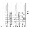
图3为本发明LED照后镜的控制电路的输入讯号及其合成的示意图。FIG. 3 is a schematic diagram of the input signal and its synthesis of the control circuit of the LED rear-view mirror of the present invention.
具体实施方式Detailed ways
为更进一步阐述本发明为达成预定发明目的所采取的技术手段及功效,以下结合附图及较佳实施例,对依据本发明提出的LED照后镜的控制电路其具体实施方式、结构、特征及其功效,详细说明如后。In order to further explain the technical means and effects that the present invention adopts to achieve the intended purpose of the invention, the specific implementation, structure and characteristics of the control circuit of the LED rear-view mirror proposed according to the present invention will be described below in conjunction with the accompanying drawings and preferred embodiments. and its efficacy are described in detail below.
请参阅图1所示,为本发明LED照后镜的控制电路的方块图;如图所示,本发明以一输入装置1与一输出装置2相连接形成主要架构,该输入装置1是以一稳压单元11、一第一震荡单元12与一第二震荡单元13并联于一电力单元10后端,该电力单元10分别提供一输入讯号Vi至该稳压单元11及该第一、二震荡单元12、13而产生不同准位或频率的稳压讯号Vs、第一震荡讯号Vs1及第二震荡讯号Vs2,该稳压讯号Vs及该第一、二震荡讯号Vs1、Vs2混合后输入该输出装置2,并分别传输至第一发光单元21及第二发光单元22,如是构成一种LED照后镜的控制电路,在本发明中该第一、二震荡单元12、13可为555震荡器。Please refer to Fig. 1, which is a block diagram of the control circuit of the LED rear mirror of the present invention; A
另请参阅图2所示,为本发明LED照后镜的控制电路的实施例示意图;图2的电路中包括一输入装置1及一输出装置2,该输入装置1与该输出装置2是相互连结,该输入装置1的电力单元10(本实施例中以车用电池为最佳)是分别传送一输入讯号Vi至该稳压单元11、第一震荡单元12及第二震荡单元13;该稳压单元11主要是为一共基型态(Common Base)的稳压电路,以齐纳二极管Zender Diode提供晶体管Q1其基极(base)与射极(emitter)的导通电压,再经二极管D1串联输出而形成一稳定的电压讯号,其中,电容C1是用以消除杂讯;而该第一、二震荡单元12、13可将该输入讯号Vi转换为具高、低准位的方波周期讯号,即第一震荡讯号Vs1与第二震荡讯号Vs2,其中,该第一、二震荡讯号Vs1、Vs2是为不同频率的讯号,在本发明实施例中,该第一震荡讯号Vs1其频率是较该第二震荡讯号Vs2低,且该第一、二震荡讯号Vs1、Vs2是具有较该稳压讯号Vs高的电位;该稳压讯号Vs及第一、二震荡讯号Vs1、Vs2混合后产生一合成讯号Vm,该合成讯号Vm是分别传输至该输出装置2的第一发光单元21及第二发光单元22,该第一、第二发光单元21、22是分别包含一恒流电路及至少一发光二极管LED1、LED2,以第一发光单元21为例,其恒流电路主要由二晶体管Q2、Q4及复数偏压电组器R2、R4、R6所构成,其中晶体管Q4的基极是连接至晶体管Q2的射极,当合成讯号Vm进入时,晶体管Q4关闭(turn off)而晶体管Q2导通(turn on),故电阻器R4上的电流是全部供应晶体管Q2作为基极电流,并结合集极电流形成射极电流而于电阻器R6上产生压降,当电阻器R6两端的电压到达预设值而提供晶体管Q4其基极与射极足以的导通电压使其导通时,晶体管Q4的集极(collector)便产生一集极电流,使原本经电阻器R4流至晶体管Q2的基极电流降低,进而导致晶体管Q2的集极电流减少,如此,若将电阻器R6上的偏压固定在预设值即可使流经发光二极管LED1的电流稳定;在本实施例中,该发光二极管LED2具有较发光二极管LED1高的导通电压,仅可被具有较高电位的第一、二震荡讯号Vs1、Vs2所驱动发光。See also shown in Fig. 2, be the embodiment schematic diagram of the control circuit of LED mirror of the present invention; In the circuit of Fig. 2, comprise an
请参阅图3所示,为本发明LED照后镜的控制电路的输入讯号及其合成的示意图;借以说明该稳压讯号Vs与该第一、二震荡讯号Vs1、Vs2及其相互加成后驱动发光二极管LED1、LED2明灭的情况,如图所示,该稳压单元11是将该电力单元10的输入讯号Vi转换成一稳定的稳压讯号Vs,可使发光二极管LED1导通而持续产生光源,而令具较高导通电压的发光二极管LED2呈恒灭状态;该第一、二震荡单元12、13是将电力单元10的输入讯号Vi分别转换为一具有高、低准位的第一、二震荡讯号Vs1、Vs2,可使发光二极管LED1、LED2于单位周期内产生明灭的闪烁态样,其中该第二震荡讯号Vs2是具有较高的频率,意即发光二极管LED1、LED2借该第二震荡讯号Vs2产生闪烁速度较快的光源;当稳压讯号Vs分别与第一、二震荡讯号Vs1、Vs2合成时,因该发光二极管LED1受稳压讯号Vs驱动故保持发光状态,而该发光二极管LED2受第一、二震荡讯号Vs1、Vs2驱动则呈闪烁状态;另外,当第一、二震荡讯号Vs1、Vs2相互合成时,发光二极管LED1、LED2是于单位周期内持续发光一段时间后,另以闪烁的型态呈现。本发明的发光二极管LED1、LED2是可为不同颜色,如蓝光及黄光,借其灯色的差异及明灭状态的不同,令本发明具有较佳辨识度,使其他驾驶人能明确分辨装设有本发明的车辆其行进的动向,以确保行车安全。Please refer to Figure 3, which is a schematic diagram of the input signal and its synthesis of the control circuit of the LED rear mirror of the present invention; in order to illustrate the voltage stabilization signal Vs and the first and second oscillating signals Vs1, Vs2 and their mutual addition. To drive the light-emitting diodes LED1 and LED2 to turn on and off, as shown in the figure, the
以上所述,仅是本发明的较佳实施例而已,并非对本发明作任何形式上的限制,虽然本发明已以较佳实施例揭露如上,然而并非用以限定本发明,任何熟悉本专业的技术人员,在不脱离本发明技术方案范围内,当可利用上述揭示的技术内容作出些许更动或修饰为等同变化的等效实施例,但凡是未脱离本发明技术方案的内容,依据本发明的技术实质对以上实施例所作的任何简单修改、等同变化与修饰,均仍属于本发明技术方案的范围内。The above description is only a preferred embodiment of the present invention, and does not limit the present invention in any form. Although the present invention has been disclosed as above with preferred embodiments, it is not intended to limit the present invention. Anyone familiar with this field Those skilled in the art, without departing from the scope of the technical solution of the present invention, can use the technical content disclosed above to make some changes or modify equivalent embodiments with equivalent changes, but all the content that does not depart from the technical solution of the present invention, according to the present invention Any simple modifications, equivalent changes and modifications made to the above embodiments by the technical essence still belong to the scope of the technical solution of the present invention.
Claims (4)
Priority Applications (1)
| Application Number | Priority Date | Filing Date | Title |
|---|---|---|---|
| CN2007101272588ACN101340765B (en) | 2007-07-03 | 2007-07-03 | LED rear mirror control circuit |
Applications Claiming Priority (1)
| Application Number | Priority Date | Filing Date | Title |
|---|---|---|---|
| CN2007101272588ACN101340765B (en) | 2007-07-03 | 2007-07-03 | LED rear mirror control circuit |
Publications (2)
| Publication Number | Publication Date |
|---|---|
| CN101340765A CN101340765A (en) | 2009-01-07 |
| CN101340765Btrue CN101340765B (en) | 2011-07-06 |
Family
ID=40214689
Family Applications (1)
| Application Number | Title | Priority Date | Filing Date |
|---|---|---|---|
| CN2007101272588AExpired - Fee RelatedCN101340765B (en) | 2007-07-03 | 2007-07-03 | LED rear mirror control circuit |
Country Status (1)
| Country | Link |
|---|---|
| CN (1) | CN101340765B (en) |
Families Citing this family (2)
| Publication number | Priority date | Publication date | Assignee | Title |
|---|---|---|---|---|
| JP6071371B2 (en)* | 2011-10-03 | 2017-02-01 | Necライティング株式会社 | Light emitting diode lamp |
| DE102015223448A1 (en)* | 2015-11-26 | 2017-06-01 | Osram Gmbh | Control device and control method for controlling a vehicle headlight, vehicle headlight with the control device and vehicle with the vehicle headlight |
Citations (3)
| Publication number | Priority date | Publication date | Assignee | Title |
|---|---|---|---|---|
| CN2216480Y (en)* | 1994-11-16 | 1996-01-03 | 吴俊达 | vehicle warning light device |
| US6888383B1 (en)* | 2003-09-08 | 2005-05-03 | National Semiconductor Corporation | Open loop LED driver system |
| CN1847054A (en)* | 2005-04-05 | 2006-10-18 | 咸瑞科技股份有限公司 | Driving circuit for vehicle light emitting device |
- 2007
- 2007-07-03CNCN2007101272588Apatent/CN101340765B/ennot_activeExpired - Fee Related
Patent Citations (3)
| Publication number | Priority date | Publication date | Assignee | Title |
|---|---|---|---|---|
| CN2216480Y (en)* | 1994-11-16 | 1996-01-03 | 吴俊达 | vehicle warning light device |
| US6888383B1 (en)* | 2003-09-08 | 2005-05-03 | National Semiconductor Corporation | Open loop LED driver system |
| CN1847054A (en)* | 2005-04-05 | 2006-10-18 | 咸瑞科技股份有限公司 | Driving circuit for vehicle light emitting device |
Also Published As
| Publication number | Publication date |
|---|---|
| CN101340765A (en) | 2009-01-07 |
Similar Documents
| Publication | Publication Date | Title |
|---|---|---|
| CN106427768B (en) | A kind of lamp control device for the direct-injection type turn signal lamp showing battery capacity | |
| CN106427767B (en) | A kind of lamp control device of the LED location lamp of display battery capacity | |
| US9321397B2 (en) | Full-screen display device of automobile taillights | |
| CN106530977A (en) | OLED position lamp capable of displaying battery level, and lamp control device thereof | |
| US12420702B2 (en) | Vehicle projection device, control method therefor, and vehicle lamp | |
| CN206594967U (en) | A kind of OLED position lamps for showing battery electric quantity | |
| CN108569198A (en) | A kind of rear combined lamp of automobile and its control method based on OLED light source | |
| CN206446514U (en) | A kind of LED location lamp for showing battery electric quantity | |
| CN207311259U (en) | A kind of rear combined lamp of automobile based on OLED light source | |
| CN101340765B (en) | LED rear mirror control circuit | |
| CN106515557A (en) | Reflection type steering signal lamp having function of displaying electric quantity of battery and lamp control device of reflection type steering signal lamp | |
| CN114633681B (en) | Automobile grille lamp with image processor | |
| CN108692278A (en) | A kind of automobile dynamic steering lamp system | |
| CN207150895U (en) | A kind of LED car lamp controller | |
| CN101190666A (en) | Vehicle LED tail light device and motor vehicle including the tail light device | |
| JP2021068689A (en) | Automobile led lighting module | |
| CN213799433U (en) | Automobile grille lamp with image processor | |
| JP6499870B2 (en) | Car interior lighting system | |
| CN108575011A (en) | A LED car light controller | |
| TWI311959B (en) | ||
| CN220701241U (en) | Headlights | |
| CN217116451U (en) | Circuit of bus type control lamp | |
| CN217917764U (en) | Have LED headlight for electric motor car of short-distance beam blast and daytime prompt facility concurrently | |
| CN108093506A (en) | A kind of daytime running lights and the LED drive circuit of position lamp multiplexing | |
| CN203005227U (en) | Vehicle lamp module |
Legal Events
| Date | Code | Title | Description |
|---|---|---|---|
| C06 | Publication | ||
| PB01 | Publication | ||
| C10 | Entry into substantive examination | ||
| SE01 | Entry into force of request for substantive examination | ||
| C14 | Grant of patent or utility model | ||
| GR01 | Patent grant | ||
| C17 | Cessation of patent right | ||
| CF01 | Termination of patent right due to non-payment of annual fee | Granted publication date:20110706 Termination date:20120703 |