CN101330099B - Fabrication of semiconductor nanowire assemblies and electrical devices comprising nanowire assemblies - Google Patents
Fabrication of semiconductor nanowire assemblies and electrical devices comprising nanowire assembliesDownload PDFInfo
- Publication number
- CN101330099B CN101330099BCN2008101360028ACN200810136002ACN101330099BCN 101330099 BCN101330099 BCN 101330099BCN 2008101360028 ACN2008101360028 ACN 2008101360028ACN 200810136002 ACN200810136002 ACN 200810136002ACN 101330099 BCN101330099 BCN 101330099B
- Authority
- CN
- China
- Prior art keywords
- nanowires
- nanowire
- light
- wire diameter
- etching
- Prior art date
- Legal status (The legal status is an assumption and is not a legal conclusion. Google has not performed a legal analysis and makes no representation as to the accuracy of the status listed.)
- Expired - Fee Related
Links
- 239000002070nanowireSubstances0.000titleclaimsabstractdescription403
- 239000004065semiconductorSubstances0.000titleclaimsabstractdescription56
- 238000004519manufacturing processMethods0.000titleabstractdescription17
- 230000000712assemblyEffects0.000title2
- 238000000429assemblyMethods0.000title2
- 239000000758substrateSubstances0.000claimsdescription79
- 239000004020conductorSubstances0.000claimsdescription69
- 238000009413insulationMethods0.000claims1
- 238000005530etchingMethods0.000abstractdescription143
- 238000000034methodMethods0.000abstractdescription95
- 238000001228spectrumMethods0.000abstractdescription17
- 238000010521absorption reactionMethods0.000abstractdescription11
- 230000008569processEffects0.000description69
- 239000010410layerSubstances0.000description50
- 230000005670electromagnetic radiationEffects0.000description17
- 230000010287polarizationEffects0.000description16
- 239000000243solutionSubstances0.000description16
- 229910052751metalInorganic materials0.000description15
- 239000002184metalSubstances0.000description15
- 239000002105nanoparticleSubstances0.000description15
- 239000002800charge carrierSubstances0.000description14
- 239000010408filmSubstances0.000description13
- 239000000203mixtureSubstances0.000description12
- 239000003054catalystSubstances0.000description9
- 239000000463materialSubstances0.000description9
- 229910052710siliconInorganic materials0.000description9
- VYPSYNLAJGMNEJ-UHFFFAOYSA-NSilicium dioxideChemical compoundO=[Si]=OVYPSYNLAJGMNEJ-UHFFFAOYSA-N0.000description8
- XUIMIQQOPSSXEZ-UHFFFAOYSA-NSiliconChemical compound[Si]XUIMIQQOPSSXEZ-UHFFFAOYSA-N0.000description8
- 238000009826distributionMethods0.000description8
- 230000003287optical effectEffects0.000description8
- 239000010703siliconSubstances0.000description8
- 238000005424photoluminescenceMethods0.000description7
- 239000000126substanceSubstances0.000description7
- 239000002019doping agentSubstances0.000description6
- 229910052737goldInorganic materials0.000description6
- 239000010931goldSubstances0.000description6
- 230000001939inductive effectEffects0.000description6
- 230000005855radiationEffects0.000description6
- PCHJSUWPFVWCPO-UHFFFAOYSA-NgoldChemical compound[Au]PCHJSUWPFVWCPO-UHFFFAOYSA-N0.000description5
- 150000002500ionsChemical class0.000description5
- 230000031700light absorptionEffects0.000description5
- 230000006798recombinationEffects0.000description5
- 238000005215recombinationMethods0.000description5
- 238000001035dryingMethods0.000description4
- 230000000977initiatory effectEffects0.000description4
- 235000012239silicon dioxideNutrition0.000description4
- 239000007787solidSubstances0.000description4
- 239000002904solventSubstances0.000description4
- 230000003595spectral effectEffects0.000description4
- ZMBHCYHQLYEYDV-UHFFFAOYSA-Ntrioctylphosphine oxideChemical compoundCCCCCCCCP(=O)(CCCCCCCC)CCCCCCCCZMBHCYHQLYEYDV-UHFFFAOYSA-N0.000description4
- LRHPLDYGYMQRHN-UHFFFAOYSA-NN-ButanolChemical compoundCCCCOLRHPLDYGYMQRHN-UHFFFAOYSA-N0.000description3
- 230000002776aggregationEffects0.000description3
- 230000008901benefitEffects0.000description3
- 238000006243chemical reactionMethods0.000description3
- 230000007423decreaseEffects0.000description3
- 239000011521glassSubstances0.000description3
- 238000002955isolationMethods0.000description3
- BASFCYQUMIYNBI-UHFFFAOYSA-NplatinumChemical compound[Pt]BASFCYQUMIYNBI-UHFFFAOYSA-N0.000description3
- 239000010453quartzSubstances0.000description3
- 239000000376reactantSubstances0.000description3
- 229910052814silicon oxideInorganic materials0.000description3
- 239000011701zincSubstances0.000description3
- XKRFYHLGVUSROY-UHFFFAOYSA-NArgonChemical compound[Ar]XKRFYHLGVUSROY-UHFFFAOYSA-N0.000description2
- LFQSCWFLJHTTHZ-UHFFFAOYSA-NEthanolChemical compoundCCOLFQSCWFLJHTTHZ-UHFFFAOYSA-N0.000description2
- 229910001218Gallium arsenideInorganic materials0.000description2
- AMQJEAYHLZJPGS-UHFFFAOYSA-NN-PentanolChemical compoundCCCCCOAMQJEAYHLZJPGS-UHFFFAOYSA-N0.000description2
- 239000004809TeflonSubstances0.000description2
- 229920006362Teflon®Polymers0.000description2
- 238000004220aggregationMethods0.000description2
- PNEYBMLMFCGWSK-UHFFFAOYSA-Naluminium oxideInorganic materials[O-2].[O-2].[O-2].[Al+3].[Al+3]PNEYBMLMFCGWSK-UHFFFAOYSA-N0.000description2
- 239000007864aqueous solutionSubstances0.000description2
- 230000001419dependent effectEffects0.000description2
- 230000000694effectsEffects0.000description2
- 239000006193liquid solutionSubstances0.000description2
- 238000004020luminiscence typeMethods0.000description2
- 238000012544monitoring processMethods0.000description2
- 239000002071nanotubeSubstances0.000description2
- 238000000206photolithographyMethods0.000description2
- 229910052697platinumInorganic materials0.000description2
- -1platinumChemical compound0.000description2
- 229910052711seleniumInorganic materials0.000description2
- 238000000926separation methodMethods0.000description2
- 229910052717sulfurInorganic materials0.000description2
- 229910052725zincInorganic materials0.000description2
- OKTJSMMVPCPJKN-UHFFFAOYSA-NCarbonChemical compound[C]OKTJSMMVPCPJKN-UHFFFAOYSA-N0.000description1
- KRHYYFGTRYWZRS-UHFFFAOYSA-MFluoride anionChemical compound[F-]KRHYYFGTRYWZRS-UHFFFAOYSA-M0.000description1
- YCKRFDGAMUMZLT-UHFFFAOYSA-NFluorine atomChemical compound[F]YCKRFDGAMUMZLT-UHFFFAOYSA-N0.000description1
- 229910005540GaPInorganic materials0.000description1
- 229910000673Indium arsenideInorganic materials0.000description1
- RTAQQCXQSZGOHL-UHFFFAOYSA-NTitaniumChemical compound[Ti]RTAQQCXQSZGOHL-UHFFFAOYSA-N0.000description1
- HCHKCACWOHOZIP-UHFFFAOYSA-NZincChemical compound[Zn]HCHKCACWOHOZIP-UHFFFAOYSA-N0.000description1
- 229910001297Zn alloyInorganic materials0.000description1
- 238000005054agglomerationMethods0.000description1
- 150000001335aliphatic alkanesChemical class0.000description1
- 125000000217alkyl groupChemical group0.000description1
- 125000003277amino groupChemical group0.000description1
- 238000013459approachMethods0.000description1
- 229910052786argonInorganic materials0.000description1
- 238000003491arrayMethods0.000description1
- 230000005540biological transmissionEffects0.000description1
- 230000015572biosynthetic processEffects0.000description1
- 230000000903blocking effectEffects0.000description1
- 125000000484butyl groupChemical group[H]C([*])([H])C([H])([H])C([H])([H])C([H])([H])[H]0.000description1
- 229910052793cadmiumInorganic materials0.000description1
- 125000003178carboxy groupChemical group[H]OC(*)=O0.000description1
- 238000005266castingMethods0.000description1
- 230000003197catalytic effectEffects0.000description1
- 238000006555catalytic reactionMethods0.000description1
- 239000000919ceramicSubstances0.000description1
- 230000008859changeEffects0.000description1
- 229910052681coesiteInorganic materials0.000description1
- 239000003086colorantSubstances0.000description1
- 229910052802copperInorganic materials0.000description1
- 229910052906cristobaliteInorganic materials0.000description1
- 239000013078crystalSubstances0.000description1
- 238000000151depositionMethods0.000description1
- 238000013461designMethods0.000description1
- 238000010586diagramMethods0.000description1
- 230000005684electric fieldEffects0.000description1
- AZHSSKPUVBVXLK-UHFFFAOYSA-Nethane-1,1-diolChemical compoundCC(O)OAZHSSKPUVBVXLK-UHFFFAOYSA-N0.000description1
- 238000001704evaporationMethods0.000description1
- 230000008020evaporationEffects0.000description1
- 230000005284excitationEffects0.000description1
- 230000005669field effectEffects0.000description1
- 229910052731fluorineInorganic materials0.000description1
- 239000011737fluorineSubstances0.000description1
- 150000002222fluorine compoundsChemical class0.000description1
- 229910052733galliumInorganic materials0.000description1
- 239000007789gasSubstances0.000description1
- 229910052732germaniumInorganic materials0.000description1
- 229910002804graphiteInorganic materials0.000description1
- 239000010439graphiteSubstances0.000description1
- RPQDHPTXJYYUPQ-UHFFFAOYSA-Nindium arsenideChemical compound[In]#[As]RPQDHPTXJYYUPQ-UHFFFAOYSA-N0.000description1
- AMGQUBHHOARCQH-UHFFFAOYSA-Nindium;oxotinChemical compound[In].[Sn]=OAMGQUBHHOARCQH-UHFFFAOYSA-N0.000description1
- 239000012212insulatorSubstances0.000description1
- 229910052742ironInorganic materials0.000description1
- 230000001678irradiating effectEffects0.000description1
- 238000000608laser ablationMethods0.000description1
- 239000007788liquidSubstances0.000description1
- 230000007246mechanismEffects0.000description1
- 229910044991metal oxideInorganic materials0.000description1
- 150000004706metal oxidesChemical class0.000description1
- 150000002739metalsChemical class0.000description1
- 239000002159nanocrystalSubstances0.000description1
- 229910052759nickelInorganic materials0.000description1
- TWNQGVIAIRXVLR-UHFFFAOYSA-Noxo(oxoalumanyloxy)alumaneChemical compoundO=[Al]O[Al]=OTWNQGVIAIRXVLR-UHFFFAOYSA-N0.000description1
- 125000001147pentyl groupChemical groupC(CCCC)*0.000description1
- 238000001259photo etchingMethods0.000description1
- 229920000642polymerPolymers0.000description1
- 238000009417prefabricationMethods0.000description1
- 238000012545processingMethods0.000description1
- BDERNNFJNOPAEC-UHFFFAOYSA-Npropan-1-olChemical compoundCCCOBDERNNFJNOPAEC-UHFFFAOYSA-N0.000description1
- 239000002096quantum dotSubstances0.000description1
- 230000009467reductionEffects0.000description1
- 230000004044responseEffects0.000description1
- 239000000377silicon dioxideSubstances0.000description1
- 229910052709silverInorganic materials0.000description1
- 239000002356single layerSubstances0.000description1
- 229910052682stishoviteInorganic materials0.000description1
- PXQLVRUNWNTZOS-UHFFFAOYSA-NsulfanylChemical class[SH]PXQLVRUNWNTZOS-UHFFFAOYSA-N0.000description1
- 239000013077target materialSubstances0.000description1
- 230000008685targetingEffects0.000description1
- 229910052714telluriumInorganic materials0.000description1
- 239000010409thin filmSubstances0.000description1
- 239000010936titaniumSubstances0.000description1
- 229910052719titaniumInorganic materials0.000description1
- 229910052905tridymiteInorganic materials0.000description1
- 238000011144upstream manufacturingMethods0.000description1
Images


Classifications
- G—PHYSICS
- G01—MEASURING; TESTING
- G01N—INVESTIGATING OR ANALYSING MATERIALS BY DETERMINING THEIR CHEMICAL OR PHYSICAL PROPERTIES
- G01N33/00—Investigating or analysing materials by specific methods not covered by groups G01N1/00 - G01N31/00
- G01N33/48—Biological material, e.g. blood, urine; Haemocytometers
- G01N33/50—Chemical analysis of biological material, e.g. blood, urine; Testing involving biospecific ligand binding methods; Immunological testing
- G01N33/53—Immunoassay; Biospecific binding assay; Materials therefor
- G01N33/543—Immunoassay; Biospecific binding assay; Materials therefor with an insoluble carrier for immobilising immunochemicals
- G01N33/54366—Apparatus specially adapted for solid-phase testing
- G01N33/54373—Apparatus specially adapted for solid-phase testing involving physiochemical end-point determination, e.g. wave-guides, FETS, gratings
- B—PERFORMING OPERATIONS; TRANSPORTING
- B82—NANOTECHNOLOGY
- B82Y—SPECIFIC USES OR APPLICATIONS OF NANOSTRUCTURES; MEASUREMENT OR ANALYSIS OF NANOSTRUCTURES; MANUFACTURE OR TREATMENT OF NANOSTRUCTURES
- B82Y10/00—Nanotechnology for information processing, storage or transmission, e.g. quantum computing or single electron logic
- B—PERFORMING OPERATIONS; TRANSPORTING
- B82—NANOTECHNOLOGY
- B82Y—SPECIFIC USES OR APPLICATIONS OF NANOSTRUCTURES; MEASUREMENT OR ANALYSIS OF NANOSTRUCTURES; MANUFACTURE OR TREATMENT OF NANOSTRUCTURES
- B82Y15/00—Nanotechnology for interacting, sensing or actuating, e.g. quantum dots as markers in protein assays or molecular motors
- B—PERFORMING OPERATIONS; TRANSPORTING
- B82—NANOTECHNOLOGY
- B82Y—SPECIFIC USES OR APPLICATIONS OF NANOSTRUCTURES; MEASUREMENT OR ANALYSIS OF NANOSTRUCTURES; MANUFACTURE OR TREATMENT OF NANOSTRUCTURES
- B82Y20/00—Nanooptics, e.g. quantum optics or photonic crystals
- B—PERFORMING OPERATIONS; TRANSPORTING
- B82—NANOTECHNOLOGY
- B82Y—SPECIFIC USES OR APPLICATIONS OF NANOSTRUCTURES; MEASUREMENT OR ANALYSIS OF NANOSTRUCTURES; MANUFACTURE OR TREATMENT OF NANOSTRUCTURES
- B82Y40/00—Manufacture or treatment of nanostructures
- H—ELECTRICITY
- H01—ELECTRIC ELEMENTS
- H01L—SEMICONDUCTOR DEVICES NOT COVERED BY CLASS H10
- H01L21/00—Processes or apparatus adapted for the manufacture or treatment of semiconductor or solid state devices or of parts thereof
- H01L21/02—Manufacture or treatment of semiconductor devices or of parts thereof
- H01L21/04—Manufacture or treatment of semiconductor devices or of parts thereof the devices having potential barriers, e.g. a PN junction, depletion layer or carrier concentration layer
- H01L21/18—Manufacture or treatment of semiconductor devices or of parts thereof the devices having potential barriers, e.g. a PN junction, depletion layer or carrier concentration layer the devices having semiconductor bodies comprising elements of Group IV of the Periodic Table or AIIIBV compounds with or without impurities, e.g. doping materials
- H01L21/30—Treatment of semiconductor bodies using processes or apparatus not provided for in groups H01L21/20 - H01L21/26
- H01L21/302—Treatment of semiconductor bodies using processes or apparatus not provided for in groups H01L21/20 - H01L21/26 to change their surface-physical characteristics or shape, e.g. etching, polishing, cutting
- H01L21/306—Chemical or electrical treatment, e.g. electrolytic etching
- H01L21/30604—Chemical etching
- H01L21/30612—Etching of AIIIBV compounds
- H—ELECTRICITY
- H10—SEMICONDUCTOR DEVICES; ELECTRIC SOLID-STATE DEVICES NOT OTHERWISE PROVIDED FOR
- H10D—INORGANIC ELECTRIC SEMICONDUCTOR DEVICES
- H10D30/00—Field-effect transistors [FET]
- H10D30/01—Manufacture or treatment
- H10D30/014—Manufacture or treatment of FETs having zero-dimensional [0D] or one-dimensional [1D] channels, e.g. quantum wire FETs, single-electron transistors [SET] or Coulomb blockade transistors
- H—ELECTRICITY
- H10—SEMICONDUCTOR DEVICES; ELECTRIC SOLID-STATE DEVICES NOT OTHERWISE PROVIDED FOR
- H10D—INORGANIC ELECTRIC SEMICONDUCTOR DEVICES
- H10D30/00—Field-effect transistors [FET]
- H10D30/40—FETs having zero-dimensional [0D], one-dimensional [1D] or two-dimensional [2D] charge carrier gas channels
- H10D30/43—FETs having zero-dimensional [0D], one-dimensional [1D] or two-dimensional [2D] charge carrier gas channels having 1D charge carrier gas channels, e.g. quantum wire FETs or transistors having 1D quantum-confined channels
- H—ELECTRICITY
- H10—SEMICONDUCTOR DEVICES; ELECTRIC SOLID-STATE DEVICES NOT OTHERWISE PROVIDED FOR
- H10D—INORGANIC ELECTRIC SEMICONDUCTOR DEVICES
- H10D62/00—Semiconductor bodies, or regions thereof, of devices having potential barriers
- H10D62/10—Shapes, relative sizes or dispositions of the regions of the semiconductor bodies; Shapes of the semiconductor bodies
- H10D62/117—Shapes of semiconductor bodies
- H10D62/118—Nanostructure semiconductor bodies
- H10D62/119—Nanowire, nanosheet or nanotube semiconductor bodies
- H10D62/122—Nanowire, nanosheet or nanotube semiconductor bodies oriented at angles to substrates, e.g. perpendicular to substrates
- H—ELECTRICITY
- H01—ELECTRIC ELEMENTS
- H01L—SEMICONDUCTOR DEVICES NOT COVERED BY CLASS H10
- H01L21/00—Processes or apparatus adapted for the manufacture or treatment of semiconductor or solid state devices or of parts thereof
- H01L21/02—Manufacture or treatment of semiconductor devices or of parts thereof
- H01L21/02104—Forming layers
- H01L21/02365—Forming inorganic semiconducting materials on a substrate
- H01L21/02518—Deposited layers
- H01L21/02521—Materials
- H—ELECTRICITY
- H01—ELECTRIC ELEMENTS
- H01L—SEMICONDUCTOR DEVICES NOT COVERED BY CLASS H10
- H01L21/00—Processes or apparatus adapted for the manufacture or treatment of semiconductor or solid state devices or of parts thereof
- H01L21/02—Manufacture or treatment of semiconductor devices or of parts thereof
- H01L21/02104—Forming layers
- H01L21/02365—Forming inorganic semiconducting materials on a substrate
- H01L21/02612—Formation types
- H01L21/02617—Deposition types
- H01L21/02636—Selective deposition, e.g. simultaneous growth of mono- and non-monocrystalline semiconductor materials
- H01L21/02639—Preparation of substrate for selective deposition
- H01L21/02645—Seed materials
- H—ELECTRICITY
- H01—ELECTRIC ELEMENTS
- H01L—SEMICONDUCTOR DEVICES NOT COVERED BY CLASS H10
- H01L21/00—Processes or apparatus adapted for the manufacture or treatment of semiconductor or solid state devices or of parts thereof
- H01L21/02—Manufacture or treatment of semiconductor devices or of parts thereof
- H01L21/02104—Forming layers
- H01L21/02365—Forming inorganic semiconducting materials on a substrate
- H01L21/02656—Special treatments
- H01L21/02664—Aftertreatments
- Y—GENERAL TAGGING OF NEW TECHNOLOGICAL DEVELOPMENTS; GENERAL TAGGING OF CROSS-SECTIONAL TECHNOLOGIES SPANNING OVER SEVERAL SECTIONS OF THE IPC; TECHNICAL SUBJECTS COVERED BY FORMER USPC CROSS-REFERENCE ART COLLECTIONS [XRACs] AND DIGESTS
- Y10—TECHNICAL SUBJECTS COVERED BY FORMER USPC
- Y10S—TECHNICAL SUBJECTS COVERED BY FORMER USPC CROSS-REFERENCE ART COLLECTIONS [XRACs] AND DIGESTS
- Y10S977/00—Nanotechnology
- Y10S977/70—Nanostructure
- Y10S977/701—Integrated with dissimilar structures on a common substrate
- Y10S977/72—On an electrically conducting, semi-conducting, or semi-insulating substrate
- Y10S977/721—On a silicon substrate
Landscapes
- Engineering & Computer Science (AREA)
- Chemical & Material Sciences (AREA)
- Health & Medical Sciences (AREA)
- Nanotechnology (AREA)
- Life Sciences & Earth Sciences (AREA)
- Physics & Mathematics (AREA)
- Immunology (AREA)
- General Physics & Mathematics (AREA)
- Crystallography & Structural Chemistry (AREA)
- Manufacturing & Machinery (AREA)
- Condensed Matter Physics & Semiconductors (AREA)
- Molecular Biology (AREA)
- Hematology (AREA)
- Biomedical Technology (AREA)
- Urology & Nephrology (AREA)
- Power Engineering (AREA)
- Microelectronics & Electronic Packaging (AREA)
- Computer Hardware Design (AREA)
- General Health & Medical Sciences (AREA)
- Microbiology (AREA)
- Chemical Kinetics & Catalysis (AREA)
- Cell Biology (AREA)
- Food Science & Technology (AREA)
- Biochemistry (AREA)
- Analytical Chemistry (AREA)
- Biotechnology (AREA)
- Medicinal Chemistry (AREA)
- General Chemical & Material Sciences (AREA)
- Pathology (AREA)
- Optics & Photonics (AREA)
- Biophysics (AREA)
- Mathematical Physics (AREA)
- Theoretical Computer Science (AREA)
- Thin Film Transistor (AREA)
- Led Devices (AREA)
- Weting (AREA)
- Crystals, And After-Treatments Of Crystals (AREA)
- Inorganic Fibers (AREA)
Abstract
Translated fromChinese
Description
Translated fromChinese本申请为分案申请,其原申请是2006年6月21日进入中国国家阶段、国际申请日为2004年12月3日的国际专利申请PCT/IB2004/052651,该原申请的中国国家申请号是200480038258.5,发明名称为“制造半导体纳米线阻以及包括纳米线阻的电器件”。This application is a divisional application. The original application is the international patent application PCT/IB2004/052651 which entered the Chinese national phase on June 21, 2006, and the international filing date is December 3, 2004. The Chinese national application number of the original application It is 200480038258.5, and the title of the invention is "Manufacturing semiconductor nanowire resistors and electrical devices including nanowire resistors."
本发明涉及用于制造具有期望的线径的半导体纳米线组的方法和设备。The present invention relates to methods and apparatus for fabricating groups of semiconducting nanowires with desired wire diameters.
本发明还涉及包括纳米线组的电器件。The invention also relates to electrical devices comprising groups of nanowires.
US-A1-2002/0,130,311公开了一种制造半导体纳米线组的方法的实施例,所述半导体纳米线具有期望的线径。纳米线是准一维导体或半导体。它们沿着纵轴延伸并且具有沿着该纵轴的从几百纳米或以下到几微米或者甚至更长的布线长度。垂直于纵轴,纳米线具有线径,该线径引起下述量子局限(quantum confinement)效应并且通常小于几百纳米。该线径可以在100nm以下并且例如可以在2与20或50nm之间的范围内。由于垂直于纵轴的相对较小的尺寸,而使诸如电子和空穴的电荷载流子被限制成垂直于纵轴,即在径向方向上。结果,电荷载流子具有由线径确定的离散量子机械能级。与此相反,由于沿着纵轴的相对较大的尺寸,而使电荷载流子不被限定在作为布线长度的函数的离散量子机械能级中。US-A1-2002/0,130,311 discloses an embodiment of a method of manufacturing a set of semiconductor nanowires having a desired wire diameter. Nanowires are quasi-one-dimensional conductors or semiconductors. They extend along a longitudinal axis and have a wiring length along the longitudinal axis of from a few hundred nanometers or less to several micrometers or even longer. Perpendicular to the longitudinal axis, the nanowires have a diameter that induces the quantum confinement effect described below and is typically smaller than a few hundred nanometers. The wire diameter can be below 100 nm and can range, for example, between 2 and 20 or 50 nm. Due to the relatively small dimension perpendicular to the longitudinal axis, charge carriers such as electrons and holes are confined perpendicular to the longitudinal axis, ie in the radial direction. As a result, the charge carriers have discrete quantum mechanical energy levels determined by the wire diameter. In contrast, due to the relatively large dimension along the longitudinal axis, charge carriers are not confined to discrete quantum mechanical energy levels as a function of wire length.
在公知的方法中,通过激光催化生长(LGG)工艺来形成GaP纳米线,即通过对固态GaP靶的激光烧蚀来产生Ga和P反应物。GaP靶包括相对少量的金,其用作纳米线生长的催化剂。相对较差地限定由此获得的纳米线的直径。或者,靶没有催化剂并且可以通过金纳米团(nanocluster)催化将反应物引入到纳米线结构中。为此,可以使用由SiO2衬底支撑的还被称作为纳米点的催化剂纳米团。反应物和金纳米点通过汽-液体-固体(VLS)生长机制产生纳米线。为了生长具有期望直径的布线,使用具有与期望的线径相似的尺寸的纳米点。以这种方式生长的纳米线具有由纳米点的平均尺寸所确定的平均线径。In a known method, GaP nanowires are formed by a laser catalytic growth (LGG) process, ie by laser ablation of a solid GaP target to generate Ga and P reactants. The GaP target includes a relatively small amount of gold, which acts as a catalyst for nanowire growth. The diameter of the nanowires thus obtained is relatively poorly defined. Alternatively, the target has no catalyst and the introduction of reactants into the nanowire structure can be catalyzed by gold nanoclusters. For this, catalyst nanoclusters, also called nanodots, supported by aSiO2 substrate can be used. The reactants and gold nanodots generate nanowires through a vapor-liquid-solid (VLS) growth mechanism. To grow wires with the desired diameter, nanodots with dimensions similar to the desired wire diameter are used. Nanowires grown in this manner have an average wire diameter determined by the average size of the nanodots.
公知方法的缺点是:不能很好地控制线径,即,经常纳米线中的至少一个不具有期望的线径。在公知的方法中,需要尺寸与期望的线径相似并且由衬底支撑的纳米点。当错误地使用一个或多个具有错误直径的纳米点时,获得一个或多个具有与期望的线径不同的线径的纳米线。此外,可能发生在需要相对高温的VLS生长期间,一个或多个纳米点与衬底分离并且与一个或多个其他纳米点聚合。从得到的成团的纳米点生长纳米线,其线径由成团的纳米点的尺寸决定而不是由单个纳米点的尺寸决定,产生线径大于期望的线径的纳米线。为了减小和在理想情况下防止这种不希望出现的聚合成团,催化剂纳米颗粒的密度由此纳米线的密度必须相对较低。A disadvantage of the known method is that the wire diameter is not well controlled, ie often at least one of the nanowires does not have the desired wire diameter. In known methods, nanodots with dimensions similar to the desired wire diameter and supported by a substrate are required. When erroneously using one or more nanodots with the wrong diameter, one or more nanowires with a wire diameter different from the desired wire diameter are obtained. Furthermore, it may happen that during VLS growth, which requires relatively high temperatures, one or more nanodots detach from the substrate and aggregate with one or more other nanodots. Nanowires are grown from the resulting clustered nanodots with wire diameters determined by the size of the clustered nanodots rather than the size of the individual nanodots, resulting in nanowires with diameters larger than desired. In order to reduce and ideally prevent this undesired aggregation of aggregates, the density of the catalyst nanoparticles and thus the density of the nanowires must be relatively low.
本发明的目的是提供一种制造半导体纳米线组的方法,其中相对较好地控制线径。It is an object of the present invention to provide a method for the manufacture of groups of semiconductor nanowires in which the diameter of the wires is relatively well controlled.
本发明由独立权利要求限定。从属权利要求限定有利的实施例。The invention is defined by the independent claims. The dependent claims define advantageous embodiments.
根据本发明,可以实现该目的是因为该方法包括以下步骤:提供预制造的半导体纳米线组,至少一个预制造的半导体纳米线的线径大于期望的线径;并且通过蚀刻来减小所述至少一个预制造的纳米线的线径,通过由所述至少一个预制造的纳米线所吸收的电磁辐射来引起蚀刻,选择电磁辐射的最小波长,使得当所述至少一个预制造的纳米线达到期望的线径时,大大减小所述至少一个预制造的纳米线的吸收。According to the invention, this object is achieved because the method comprises the steps of: providing a set of prefabricated semiconducting nanowires, at least one of which has a diameter larger than the desired diameter; and reducing said The wire diameter of at least one prefabricated nanowire is etched by electromagnetic radiation absorbed by the at least one prefabricated nanowire, the minimum wavelength of the electromagnetic radiation is selected such that when the at least one prefabricated nanowire reaches The absorption of the at least one prefabricated nanowire is greatly reduced when the desired wire diameter is obtained.
为了减小线径大于期望的线径的所述至少一个预制造的半导体纳米线的线径,对预制造的半导体纳米线组进行由电磁辐射引起的蚀刻处理。从US-4,518,456中获知的由电磁辐射引起的蚀刻处理是一种其中将要被蚀刻的半导体物体例如放置在如H3PO4或HCl的水溶液中的方法。在物体与溶液接触的同时,通过电磁辐射照射该物体要被蚀刻的部分。电磁辐射对于肉眼可以是可见的或不可见的,并且在该申请的下文中被简称为“光”。光至少部分被将要蚀刻的物体吸收,由此产生电子和空穴。这些光产生的电荷载流子,即电子和/或空穴,然后扩散并在物体与溶液之间的界面处引起化学反应。在这些在现有技术中还被称为光蚀刻的化学反应过程中,将纳米线的原子离子化并使其溶解在溶液中。可以通过光产生的电荷载流子例如空穴来引起这些原子的离子化。溶解由此产生的离子的工艺可以包括将这些离子与溶液中的离子化合。后一种离子可以由光产生的电荷载流子例如电子引起。对于含有溶液的氟中的InP,六个空穴可以从InP中形成In3+和P3+。。这些正离子可以与负的氟离子F-化合,其是通过使F2+2电子产生2F-的反应而形成的。本领域公知的相似工艺可以用于其他的纳米线组分物。In order to reduce the wire diameter of the at least one prefabricated semiconductor nanowire having a wire diameter larger than the desired wire diameter, the group of prefabricated semiconductor nanowires is subjected to an etching treatment caused by electromagnetic radiation. An etching process caused by electromagnetic radiation known from US-4,518,456 is a method in which the semiconductor object to be etched is placed, for example, in an aqueous solution such as H3 PO4 or HCl. While the object is in contact with the solution, the portion of the object to be etched is irradiated with electromagnetic radiation. Electromagnetic radiation may or may not be visible to the naked eye and is referred to simply as "light" hereinafter in this application. The light is at least partially absorbed by the object to be etched, thereby generating electrons and holes. These photogenerated charge carriers, electrons and/or holes, then diffuse and cause chemical reactions at the interface between the object and the solution. During these chemical reactions, also known in the prior art as photolithography, the atoms of the nanowires are ionized and dissolved in solution. Ionization of these atoms can be induced by photogenerated charge carriers such as holes. The process of dissolving the ions thus produced may include combining these ions with ions in solution. The latter ions can be induced by photogenerated charge carriers such as electrons. For InP in fluorine containing solution, six holes can form In3+ and P3+ from InP. . These positive ions can combine with the negative fluoride ion, F− , which is formed by the reaction of F2 +2 electrons to produce 2F− . Similar processes known in the art can be used for other nanowire compositions.
在本申请中,术语“半导体”表示一类其中可以例如以上述方式通过引发蚀刻的光来产生电子空穴对的材料。如果没有不同的陈述,在该申请的剩余部分中,术语“纳米线”意味着半导体纳米线。In this application, the term "semiconductor" denotes a class of materials in which electron-hole pairs can be generated, for example in the manner described above, by light inducing etching. If not stated otherwise, in the remainder of this application the term "nanowire" means semiconductor nanowire.
如上所述,蚀刻需要由预制造的纳米线来吸收光。由于量子机械局限,由光所产生的电子和空穴可用的量子机械能级取决于线径。随着线径减小,能级之间的间隔,即导带与价带之间的间隔,也被称为带隙,也增加并且相应地需要较大的能量来产生电子空穴对。As mentioned above, etching requires light absorption by the prefabricated nanowires. Due to quantum mechanical limitations, the available quantum mechanical energy levels for electrons and holes generated by light depend on the wire diameter. As the wire diameter decreases, the separation between the energy levels, that is, the separation between the conduction band and the valence band, also known as the bandgap, also increases and correspondingly greater energy is required to generate electron-hole pairs.
当使用具有给定波长λ的光时,存在某一线径,在该线径下,光子的能量不再足以产生电子空穴对。结果,大大地减小了蚀刻效率。蚀刻工艺实际上停止,即蚀刻处理自行终止。通过适当地选择光的光谱,尤其是最短的波长,在下文中被称为光谱的最小波长,当至少一个预制造的纳米线具有期望的线径时可以实现蚀刻处理的自行终止。由于这种自行终止,而在所获得的半导体纳米线组中,相对较好地控制线径。该方法具有另外的优点:线径不取决于在公知方法中所使用的用来控制线径的纳米点的尺寸。因此,在根据本发明蚀刻纳米线之后,纳米点的尺寸并不重要并且偶然的纳米点的聚合成团不会产生具有大于期望的线径的线径的纳米线。When using light with a given wavelength λ, there exists a certain path at which the energy of the photons is no longer sufficient to generate electron-hole pairs. As a result, etching efficiency is greatly reduced. The etching process is actually stopped, ie the etching process terminates itself. By properly selecting the spectrum of light, especially the shortest wavelength, hereinafter referred to as the minimum wavelength of the spectrum, self-termination of the etching process can be achieved when at least one prefabricated nanowire has a desired wire diameter. Due to this self-termination, the wire diameter is relatively well controlled in the obtained set of semiconducting nanowires. This method has the additional advantage that the wire diameter does not depend on the size of the nanodots used in known methods to control the wire diameter. Thus, after etching the nanowires according to the invention, the size of the nanodots is not critical and accidental agglomeration of nanodots will not result in nanowires with wire diameters larger than desired.
每一个期望的线径对应于某一波长,其值取决于纳米线的化学组成。通常对于越小的线径,需要越短的光波长。假如最短的波长对应于期望的线径,则可以使用包括几个各自具有不同波长的光谱分量的光来代替具有单个波长的光。换句话说,选择光的光谱使得当至少一个预制造的纳米线达到期望的线径时显著地减小该至少一个预制造的纳米线的吸收。Each desired wire diameter corresponds to a certain wavelength, the value of which depends on the chemical composition of the nanowire. Typically for smaller wire diameters, shorter wavelengths of light are required. Provided that the shortest wavelength corresponds to the desired wire diameter, light comprising several spectral components each having a different wavelength may be used instead of light having a single wavelength. In other words, the spectrum of light is selected such that the absorption of the at least one prefabricated nanowire is substantially reduced when the at least one prefabricated nanowire reaches a desired wire diameter.
对于纳米线,由光所产生的电子和空穴可用的量子机械能级不取决于布线长度,如以上讨论的那样。因此,根据本发明的方法用于所有的纳米线,而与它们的布线长度无关。For nanowires, the quantum mechanical energy levels available to photogenerated electrons and holes do not depend on wire length, as discussed above. Therefore, the method according to the invention is used for all nanowires irrespective of their wiring length.
从D.Talapin等人发表在2002年的Journal of Physical Chemistry B的106卷第12659-12663页上的文章“Etching of colloidal InP nanocrystals withfluorides:photochemical nature of the process resulting in highphotoluminescence efficiency”中,获知可以蚀刻尺寸为5.2nm或以下的纳米点。根据该文章,通过由纳米点吸收的光来引起蚀刻。选择光的光谱使得当纳米点达到期望的尺寸时显著减小纳米点的吸收。From the article "Etching of collagenal InP nanocrystals with fluorides: photochemical nature of the process resulting in high photoluminescence efficiency" published by D.Talapin et al. Nanodots with a size of 5.2 nm or less. According to the article, etching is induced by light absorbed by the nanodots. The spectrum of light is chosen such that the absorption of the nanodots is substantially reduced when the nanodots reach the desired size.
对于纳米点,由光所产生的电子和空穴可用的量子机械能级取决于纳米点的尺寸,即取决于所有三个方向上的尺寸。相反,根据本发明的方法与三个尺寸中的一个无关,即与布线长度无关。因此,根据Talapin的这篇文章的方法不能在独立于它们的布线长度的情况下用于所有的纳米线。For nanodots, the quantum mechanical energy levels available to photogenerated electrons and holes depend on the size of the nanodot, ie on dimensions in all three directions. In contrast, the method according to the invention is independent of one of the three dimensions, ie the wiring length. Therefore, the method according to this article by Talapin cannot be used for all nanowires independently of their wiring length.
可以通过任何用于制造纳米线的公知方法例如LCG或VLS方法来获得所提供的预制造的纳米线。或者,纳米线例如可以通过从单晶对它们进行蚀刻来获得。The provided prefabricated nanowires can be obtained by any known method for manufacturing nanowires, such as LCG or VLS methods. Alternatively, nanowires can be obtained, for example, by etching them from single crystals.
可以将预制造的纳米线附着到衬底上,可以使它们分散在液体溶液中或者可以将它们松散地布置在衬底上。Prefabricated nanowires can be attached to a substrate, they can be dispersed in a liquid solution, or they can be arranged loosely on the substrate.
纳米线组可以包括一个或多个纳米线。A set of nanowires may include one or more nanowires.
期望的线径可以是一个直径,或者当纳米线组包括一个以上的纳米线时,它可以是许多的针对各纳米线的线径。The desired wire diameter may be one diameter, or when the set of nanowires includes more than one nanowire, it may be a number of wire diameters for each nanowire.
纳米线组可以包括纳米线的选择,所述纳米线包括在衬底上或溶液中。The set of nanowires may include a selection of nanowires included on a substrate or in solution.
纳米线可以具有一致的组成物,即它们可以具有相同的作为线径和布线长度的函数的化学组成。或者,一些或所有的纳米线具有不一致的组成物,即它们可以具有作为线径和/或布线长度的函数的化学组成。由于半导体纳米线的掺杂而可以改变化学组成,其取决于线径和/或布线长度。Nanowires can have a consistent composition, ie they can have the same chemical composition as a function of wire diameter and wire length. Alternatively, some or all of the nanowires have a non-uniform composition, ie they may have a chemical composition as a function of wire diameter and/or wire length. The chemical composition can be changed due to the doping of the semiconductor nanowires, which depends on the wire diameter and/or wiring length.
在本申请中,术语“纳米线”表示具有实心的纳米线和具有空心的纳米线。在本领域中,后者还被称为纳米管。而且在后一种类型的纳米线中,由于垂直于纵轴的尺寸相对较小,所以诸如电子和空穴的电荷载流子被限定成垂直于纵轴,即限定在径向上。结果,电荷载流子具有离散的量子机械能级,其主要由限定这种类型的纳米线的中心的厚度决定。由于沿着纵轴的尺寸相对较大,所以不将电荷载流子限制在作为布线长度的函数的离散量子机械能级中,类似于具有实心的纳米线。当纳米线具有空心时,线径是指中心的厚度。中心的厚度是外线径与内线径的差,即中空部分的直径。In this application, the term "nanowire" means a nanowire with a solid core and a nanowire with a hollow core. In the art, the latter are also known as nanotubes. Also in the latter type of nanowires, due to the relatively small dimensions perpendicular to the longitudinal axis, charge carriers such as electrons and holes are confined perpendicular to the longitudinal axis, ie in the radial direction. As a result, charge carriers have discrete quantum-mechanical energy levels that are largely determined by the thickness that defines the center of this type of nanowire. Due to the relatively large dimension along the longitudinal axis, the charge carriers are not confined to discrete quantum mechanical energy levels as a function of wire length, similar to having a solid nanowire. When the nanowire has a hollow center, the wire diameter refers to the thickness of the center. The thickness of the center is the difference between the outer wire diameter and the inner wire diameter, which is the diameter of the hollow part.
在一个实施例中,使用辐射源,其发射引发蚀刻的电磁辐射以及除此之外的波长短于最小波长的电磁辐射。对由辐射源发出的电磁辐射进行光谱滤波以充分减少波长短于最小波长的电磁辐射。后一种波长短于最小波长的电磁辐射能够引发对具有期望的线径的预制造的半导体纳米线的蚀刻,即该电磁辐射具有比某一特定波长短的波长,在所述特定波长下蚀刻工艺在期望的线径下终止。在将电磁辐射射到预制造的纳米线上之前,对由辐射源发射的电磁辐射进行光谱过滤以充分减少波长短于最小波长的电磁辐射。这样,充分减小并且优选地有效防止对具有期望的线径的预制造的半导体纳米线的蚀刻。在本申请中,术语“光源”用作术语“辐射源”的同义词。术语“光源”不限于发射可见的电磁辐射的辐射源,而且可以包括发射对于肉眼来说不可见的电磁辐射的辐射源。In one embodiment, a radiation source is used which emits the etching-initiating electromagnetic radiation and otherwise electromagnetic radiation having a wavelength shorter than the minimum wavelength. The electromagnetic radiation emitted by the radiation source is spectrally filtered to substantially reduce electromagnetic radiation having wavelengths shorter than a minimum wavelength. The latter electromagnetic radiation having a wavelength shorter than the minimum wavelength, i.e. the electromagnetic radiation having a wavelength shorter than a certain wavelength at which the etching The process terminates at the desired wire diameter. Electromagnetic radiation emitted by the radiation source is spectrally filtered to substantially reduce electromagnetic radiation having wavelengths shorter than a minimum wavelength prior to directing the electromagnetic radiation onto the prefabricated nanowire. In this way, etching of prefabricated semiconductor nanowires having a desired wire diameter is substantially reduced and preferably effectively prevented. In this application, the term "light source" is used as a synonym for the term "radiation source". The term "light source" is not limited to radiation sources that emit visible electromagnetic radiation, but may include radiation sources that emit electromagnetic radiation that is invisible to the naked eye.
在一个实施例中,在减小线径的步骤之前,预制造的半导体纳米线具有大于或等于期望的线径的线径。在减小线径的步骤期间,对线径大于期望的线径的预制造的纳米线进行蚀刻直到它们具有期望的线径。这样,获得基本上具有相同的期望的线径的纳米线组,这可由包含在光谱中的最短波长所决定。由于纳米线的带隙直接与光引发蚀刻的终止有关,所以基本上该组所有的纳米线具有相同的带隙,所述带隙由包含在光谱中的最短波长所决定。In one embodiment, prior to the step of reducing the wire diameter, the prefabricated semiconductor nanowire has a wire diameter greater than or equal to the desired wire diameter. During the wire diameter reducing step, prefabricated nanowires having wire diameters larger than the desired wire diameter are etched until they have the desired wire diameter. In this way, groups of nanowires are obtained having substantially the same desired wire diameter, which can be determined by the shortest wavelength contained in the spectrum. Since the bandgap of the nanowires is directly related to the termination of photo-induced etching, essentially all nanowires of the group have the same bandgap determined by the shortest wavelength contained in the spectrum.
可以沿着轴对引发蚀刻处理的光进行线性偏振。通常,由半导体纳米线进行的光吸收是偏振选择性的。平行于纳米线的纵轴偏振的光,与垂直于该轴偏振的光相比,被纳米线更为有效地吸收。当半导体纳米线周围的介质具有与半导体纳米线不同的介电常数时,该差异特别大。通过利用线性偏振光,蚀刻效率取决于纳米线的取向:平行于轴取向的纳米线被相对有效地蚀刻,而垂直于轴取向的纳米线被相对无效地蚀刻。以中间蚀刻效率来蚀刻纵轴取向既不平行于偏振轴又不垂直于偏振轴的中间纳米线,所述中间蚀刻效率是纵轴与偏振轴之间的角度的函数。这样,可以获得具有依赖于取向的线径的纳米线组。The light that initiates the etching process can be linearly polarized along the axis. In general, light absorption by semiconductor nanowires is polarization selective. Light polarized parallel to the longitudinal axis of the nanowire is more efficiently absorbed by the nanowire than light polarized perpendicular to that axis. This difference is particularly large when the medium surrounding the semiconducting nanowire has a different dielectric constant than the semiconducting nanowire. By utilizing linearly polarized light, the etching efficiency depends on the orientation of the nanowires: nanowires oriented parallel to the axis are etched relatively efficiently, while nanowires oriented perpendicular to the axis are etched relatively ineffectively. Intermediate nanowires with their longitudinal axes oriented neither parallel nor perpendicular to the polarization axis are etched with an intermediate etch efficiency as a function of the angle between the longitudinal axis and the polarization axis. In this way, groups of nanowires with orientation-dependent wire diameters can be obtained.
引发蚀刻处理的光可以包括沿着第一轴被线性偏振的第一分量和沿着第二轴被线性偏振的第二分量,该第二轴与第一轴形成大于零的角度。这样,可以以与平行于第二轴取向的纳米线不同的方式蚀刻平行于第一轴取向的纳米线。第一轴可以垂直于第二轴。为此,可以调整两个分量的光谱特性和/或强度。可以同时或依次、即一个接一个地提供第一分量和第二分量。或者,可以部分同时地提供它们,即在某一时间段内一起提供这两个分量,而在另一时间段内,提供两个分量中的一个而不提供另一个。The light inducing the etching process may include a first component linearly polarized along a first axis and a second component linearly polarized along a second axis forming an angle greater than zero with the first axis. In this way, nanowires oriented parallel to the first axis can be etched differently than nanowires oriented parallel to the second axis. The first axis may be perpendicular to the second axis. To this end, the spectral properties and/or intensities of the two components can be adjusted. The first and second components may be provided simultaneously or sequentially, ie one after the other. Alternatively, they may be provided partially simultaneously, ie the two components are provided together during a certain period of time, and during another period of time, one of the two components is provided without the other.
当第一分量含有具有第一最小波长的第一光谱,而第二分量含有具有与第一最小波长不同的第二最小波长的第二光谱时,将平行于第一轴取向的纳米线蚀刻到由第一最小波长确定的线径,而将平行于第二轴取向的纳米线蚀刻到由第二最小波长确定的线径。因此可以获得在化学上一致的纳米线组,该组的纳米线根据它们的取向而具有不同的线径。换句话说,获得具有一致的化学组成的纳米线组,该纳米线组具有各向异性的带隙。When the first component contains a first spectrum having a first minimum wavelength and the second component contains a second spectrum having a second minimum wavelength different from the first minimum wavelength, etching the nanowires oriented parallel to the first axis into The wire diameter is determined by the first minimum wavelength, while the nanowires oriented parallel to the second axis are etched to the wire diameter determined by the second minimum wavelength. It is thus possible to obtain a chemically consistent set of nanowires having different wire diameters depending on their orientation. In other words, a group of nanowires with a uniform chemical composition and an anisotropic band gap is obtained.
另一种获得带隙在纳米线组中的各向异性分布的方法是基于蚀刻速率对吸收并且由此对光强度的依赖性。在一个实施例中,第一分量具有第一强度,而第二向量具有与第一强度不同的第二强度。结果,依赖于取向来对例如随机取向的纳米线组进行蚀刻。与主要平行于第二轴的纳米线相比,主要平行于第一轴的纳米线被更为有效地蚀刻。在一个实施例中,第二强度基本上为零,并且平行于第二轴的纳米线根本没被蚀刻。结果,可以获得具有期望的线径的纳米线组,该组的所有纳米线具有平行于第二轴的纵向方向。Another approach to obtain anisotropic distribution of the band gap in the nanowire group is based on the dependence of the etch rate on absorption and thus on light intensity. In one embodiment, the first component has a first intensity and the second vector has a second intensity different from the first intensity. As a result, groups of, for example, randomly oriented nanowires are etched in dependence on the orientation. Nanowires that are primarily parallel to the first axis are etched more efficiently than nanowires that are primarily parallel to the second axis. In one embodiment, the second intensity is substantially zero, and nanowires parallel to the second axis are not etched at all. As a result, a group of nanowires having a desired wire diameter can be obtained, all nanowires of the group having a longitudinal direction parallel to the second axis.
根据本发明的另一方案,期望的线径可以包括零,即通过由光引发的蚀刻将至少一个预制造的纳米线从预制造的纳米线组中除去。发明人已经理解的是,线径小于某一阈值的纳米线不再稳定,即它们破碎并且被有效地蚀刻掉。阈值通常取决于纳米线的化学组成并且可以远小于3nm,例如大约1nm。According to another aspect of the invention, the desired wire diameter may include zero, ie at least one prefabricated nanowire is removed from the group of prefabricated nanowires by photo-induced etching. The inventors have understood that nanowires with diameters below a certain threshold are no longer stable, ie they break and are effectively etched away. The threshold generally depends on the chemical composition of the nanowire and can be much smaller than 3 nm, for example about 1 nm.
线径小于或等于阈值的纳米线的不稳定性可以用于从预制造的纳米线组中除去纳米线。为此,使用包含由线径小于或等于阈值的纳米线所吸收的波长的光。该光引发对纳米线的蚀刻,使其降到某一线径,在该线径下纳米线破碎并由此消失。The instability of nanowires with wire diameters less than or equal to a threshold value can be used to remove nanowires from a prefabricated set of nanowires. For this, light containing wavelengths absorbed by nanowires having a wire diameter smaller than or equal to the threshold value is used. The light induces etching of the nanowires down to a certain diameter at which the nanowires break and thereby disappear.
当引起对期望的线径为零的纳米线进行蚀刻的光被线性偏振时,可以除去纵轴平行于光偏振的纳米线,而纵轴垂直于光的偏振方向的纳米线远远没有被有效地蚀刻。这样,可以除去基本上所有的平行于偏振方向的纳米线。当施加光甚至更长时间时,除去基本上所有的大体上不垂直于偏振方向的纳米线,并且获得沿着垂直于偏振方向的轴取向的纳米线组。由于没有对剩余的纳米线进行有效的蚀刻,所以它们具有基本上不变的线径分布。When the light that causes the etching of the desired zero-diameter nanowires is linearly polarized, nanowires whose longitudinal axis is parallel to the polarization of the light can be removed, while nanowires whose longitudinal axis is perpendicular to the polarization of the light are far less effective. etched. In this way, substantially all nanowires parallel to the polarization direction can be removed. When light is applied for an even longer time, substantially all nanowires substantially not perpendicular to the direction of polarization are removed and groups of nanowires oriented along an axis perpendicular to the direction of polarization are obtained. Since the remaining nanowires were not effectively etched, they had a substantially unchanged wire size distribution.
可以将预制造的纳米线分布在表面上或体积内,并且可以将引发对期望的线径为零的纳米线进行蚀刻的光施加到表面或体积的一部分。结果,可以将纳米线从表面或体积的被照射部分中除去,而不将其从表面或体积的剩余部分中除去。可以通过将光聚焦在要被照射的部分上来照射该部分。或者,可以通过诸如光刻掩模的掩模来部分地阻挡光。Prefabricated nanowires can be distributed on a surface or within a volume, and light that induces etching of the desired zero-diameter nanowires can be applied to a portion of the surface or volume. As a result, the nanowires can be removed from the irradiated portion of the surface or volume without removing them from the remainder of the surface or volume. The portion to be illuminated can be irradiated by focusing light on the portion. Alternatively, light may be partially blocked by a mask such as a photolithography mask.
根据本发明的另一个方案,预制造的半导体纳米线可以由衬底支撑。预制造的半导体纳米线可以位于表面上,可以将它们附着到表面和/或可以使它们与表面化学键合。如上所述,由于纳米线中的电荷载流子的量子局限,而使光引发的蚀刻处理自行终止。发明人已经理解的是,当由衬底支撑纳米线时没有显著地干扰量子局限。迄今为止这是令人惊讶的,因为衬底附近通常改变电荷载流子可用的量子机械能级。然而,发明人观察到量子机械能级的这种改变相对较小,并且蚀刻在基本相同的线径下自行终止。甚至当衬底是电导体并且预制造的半导体纳米线电连接到衬底时,该效应也发生。这种具有附着到其的纳米线的衬底对于制造包括这种纳米线的电器件来说是非常好的起点。According to another aspect of the invention, prefabricated semiconductor nanowires may be supported by a substrate. Prefabricated semiconducting nanowires can be located on the surface, they can be attached to the surface and/or they can be chemically bonded to the surface. As mentioned above, the photo-induced etching process is self-terminating due to the quantum confinement of the charge carriers in the nanowires. The inventors have appreciated that quantum confinement is not significantly disturbed when the nanowires are supported by a substrate. This has been surprising so far, since the vicinity of the substrate generally changes the quantum mechanical energy levels available to charge carriers. However, the inventors observed that this change in quantum mechanical energy level was relatively small, and the etch terminated itself at substantially the same wire diameter. This effect occurs even when the substrate is an electrical conductor and the prefabricated semiconductor nanowires are electrically connected to the substrate. Such a substrate with nanowires attached thereto is a very good starting point for fabricating electrical devices comprising such nanowires.
衬底可以具有由支撑预制造的半导体纳米线的部分和在该部分之外的另一部分构成的表面,至少另一部分为抗蚀剂。术语抗蚀剂意味着光引发的蚀刻不会或基本上不会改变表面。这样,在对纳米线的蚀刻期间,不对衬底的表面进行蚀刻。其基本上保持其初始的形状。这在将由衬底支撑的纳米线附着到衬底时是特别有利的,因为否则在蚀刻处理期间纳米线会发生分离,这可能使得纳米线在电器件中的应用变得更加复杂。The substrate may have a surface consisting of a portion supporting the prefabricated semiconductor nanowires and another portion other than the portion, at least the other portion being a resist. The term resist means that photo-induced etching does not or substantially does not alter the surface. In this way, the surface of the substrate is not etched during the etching of the nanowires. It substantially retains its original shape. This is particularly advantageous when attaching nanowires supported by a substrate to a substrate, since detachment of the nanowires would otherwise occur during the etching process, which may complicate the use of the nanowires in electrical devices.
衬底可以具有一致的组成物,该组成物是抗蚀剂。在另一实施例中,衬底包括不是抗蚀剂的第一层以及为抗蚀剂的第二层,第二层构成表面。第一层和第二层的组合允许获得期望的抗蚀剂表面,同时可以由第一层来提供不能由第二层单独提供的其他期望的衬底特性。第一层例如可以在机械上是刚性的,而第二层独自,即在没有第一层的情况下,在机械上不是刚性的。第一层可以是导电的,而第二层独自是绝缘的。如果第二层通过化学键连接到第一层则这经常是有利的,所述第二层是抗蚀剂,即基本上不被蚀刻处理所破坏。这确保在蚀刻处理期间由第二层很好地保护第一层,在蚀刻之后留下完整无缺的衬底。The substrate can have a consistent composition, which is resist. In another embodiment, the substrate comprises a first layer that is not a resist and a second layer that is a resist, the second layer constituting the surface. The combination of the first layer and the second layer allows a desired resist surface to be obtained, while other desirable substrate properties that cannot be provided by the second layer alone may be provided by the first layer. For example, the first layer can be mechanically rigid, while the second layer alone, ie without the first layer, is not mechanically rigid. The first layer may be conductive, while the second layer alone is insulating. It is often advantageous if the second layer is chemically bonded to the first layer, said second layer being resist, ie substantially not damaged by the etching process. This ensures that the first layer is well protected by the second layer during the etching process, leaving the substrate intact after etching.
如果第二层由选自烷基三乙氧基硅氧烷和烷基三甲氧基硅氧烷的一种或多种材料构成则这是有利的。这些材料可以形成有效保护第一层的层,所述第一层可以由选自硅、氧化硅、氧化铝、诸如铂的金属或聚合物的一种或多种元素构成。上述用于第二层的材料具有的优点是:例如由一个单层构成的相对薄层已经对第一层产生有效的保护。这是特别有利的,因为纳米线可以由第二层部分包围,被包围的部分也被保护不受蚀刻的影响。这产生在其由衬底支撑的端部没有被蚀刻或没有被有效蚀刻的纳米线。通过利用相对较薄的第二层,使没有被蚀刻或没有被有效蚀刻的纳米线的部分保持得较小。It is advantageous if the second layer consists of one or more materials selected from the group consisting of alkyltriethoxysiloxanes and alkyltrimethoxysiloxanes. These materials may form a layer effective to protect the first layer, which may consist of one or more elements selected from silicon, silicon oxide, aluminum oxide, metals such as platinum, or polymers. The aforementioned materials for the second layer have the advantage that a relatively thin layer, for example consisting of a single layer, already produces effective protection for the first layer. This is particularly advantageous because the nanowires can be partially surrounded by the second layer, the surrounded part being also protected from etching. This results in nanowires that are not etched, or not effectively etched, at their ends supported by the substrate. By using a relatively thin second layer, the portion of the nanowire that is not etched or not etched efficiently is kept small.
当提供预制造的半导体纳米线的步骤包括以下子步骤时:提供衬底,该衬底不是抗蚀剂;并且在衬底的表面上生长半导体纳米线,所生长的纳米线是预制造的半导体纳米线,如果在通过蚀刻减小至少一个预制造的纳米线的线径的步骤之前,用抗蚀剂层覆盖在提供预制造的半导体纳米线的步骤之后暴露出来的衬底表面,则这是有利的。换句话说,在生长纳米线之后提供抗蚀剂层。例如通过VLS生长来生长纳米线需要相对较高的温度。通过在纳米线的生长之后提供抗蚀剂层,确保抗蚀剂层不经受这些相对较高的温度。由此可以使用由不能承受这些温度的材料构成的抗蚀剂层。When the step of providing a prefabricated semiconductor nanowire comprises the substeps of: providing a substrate, which is not a resist; and growing a semiconductor nanowire on a surface of the substrate, the grown nanowire being a prefabricated semiconductor Nanowires, if the surface of the substrate exposed after the step of providing prefabricated semiconductor nanowires is covered with a resist layer before the step of reducing the wire diameter of at least one prefabricated nanowire by etching, then this is advantageous. In other words, the resist layer is provided after growing the nanowires. For example growing nanowires by VLS growth requires relatively high temperatures. By providing the resist layer after the growth of the nanowires it is ensured that the resist layer is not subjected to these relatively high temperatures. Resist layers made of materials which cannot withstand these temperatures can thus be used.
在许多的实施例中,将预制造的半导体纳米线分布在衬底的表面区域上。于是由第一光强度照射表面区域的一部分,而由小于第一光强度的第二光强度照射在该表面部分之外的另一表面部分是有利的。这样,在表面的一部分中引发对预制造的半导体纳米线的相对有效的蚀刻,而在表面的另一部分中基本上没有对预制造的半导体纳米线进行有效蚀刻,因为蚀刻效率与光强度成比例。这样,可以获得在一部分和另一部分中具有不同线径的纳米线的衬底。为此,当表面的一部分中的纳米线的线径由于蚀刻工艺的自行终止而不再改变时可以停止照射。当将这两部分集成在发光器件中时,可以获得与两种不同的线径相对应的两种不同的颜色。在一个实施例中,第二光强度基本上为零,即基本上不对表面的另一部分上的纳米线进行蚀刻。In many embodiments, prefabricated semiconductor nanowires are distributed over the surface area of the substrate. It is then advantageous to irradiate a part of the surface region with a first light intensity, while another surface part outside this surface part is irradiated with a second light intensity which is lower than the first light intensity. In this way, a relatively efficient etching of the prefabricated semiconductor nanowires is induced in one part of the surface, while substantially no effective etching of the prefabricated semiconductor nanowires occurs in another part of the surface, because the etching efficiency is proportional to the light intensity . In this way, a substrate having nanowires having different wire diameters in one part and another part can be obtained. For this purpose, the irradiation can be stopped when the diameter of the nanowires in a part of the surface no longer changes due to the self-termination of the etching process. When these two parts are integrated in a light emitting device, two different colors corresponding to two different wire diameters can be obtained. In one embodiment, the second light intensity is substantially zero, ie substantially does not etch the nanowires on the other portion of the surface.
在另一实施例中,将预制造的半导体纳米线分布在衬底的表面区域上,由具有第一最小波长的光照射表面区域的第一部分,由具有不同于第一波长的第二最小波长的光照射在该表面部分之外的表面的第二部分。而且,在这种情况下,可以获得在一部分和另一部分中具有不同线径的纳米线的衬底。当蚀刻纳米线直到蚀刻自行终止时,分别由第一最小波长和第二最小波长来确定线径。这具有的优点是:与上述实施例相比,线径的控制相对可靠。In another embodiment, prefabricated semiconductor nanowires are distributed over a surface area of a substrate, a first portion of the surface area is illuminated by light having a first minimum wavelength, and by light having a second minimum wavelength different from the first wavelength The light impinges on a second portion of the surface other than that surface portion. Also, in this case, a substrate having nanowires having different wire diameters in one part and another part can be obtained. When the nanowire is etched until the etching terminates itself, the wire diameter is determined by the first minimum wavelength and the second minimum wavelength, respectively. This has the advantage that the control of the wire diameter is relatively reliable compared to the above-described embodiments.
根据本发明的电器件可以包括半导体纳米线组,该组包括各自具有第一线径的第一纳米线子组和各自具有不同于第一线径的第二线径的第二纳米线子组,将第一子组的纳米线附着到衬底的第一部分,将第一子组的纳米线附着到衬底在第一部分之外的第二部分。这种电器件例如可以是发光器件,在该发光器件中,可以分别通过第一和第二子组的纳米线来发射不同波长的光。该电器件可以是集成电路,其中纳米线用作其电性能取决于带隙并且由此取决于线径的半导体元件。例子为晶体管,例如金属氧化物半导体场效应晶体管(MOSFET)和双极性晶体管,在所述MOSFET中纳米线构成半导体衬底。MOSFET的阈值电压取决于纳米线的带隙。因此在同一电器件中可以获得具有不同阈值电压的晶体管。或者,半导体元件可以包括二极管。An electrical device according to the present invention may comprise a group of semiconductor nanowires comprising a first subgroup of nanowires each having a first wire diameter and a second subgroup of nanowires each having a second wire diameter different from the first wire diameter, A first subset of nanowires is attached to a first portion of the substrate, and the first subset of nanowires is attached to a second portion of the substrate other than the first portion. Such an electrical device can be, for example, a light emitting device in which light of different wavelengths can be emitted by the first and second subgroups of nanowires, respectively. The electrical device may be an integrated circuit in which the nanowires are used as semiconductor elements whose electrical properties depend on the band gap and thus on the wire diameter. Examples are transistors such as Metal Oxide Semiconductor Field Effect Transistors (MOSFETs) and bipolar transistors in which the nanowires form the semiconductor substrate. The threshold voltage of the MOSFET depends on the bandgap of the nanowire. Transistors with different threshold voltages can thus be obtained in the same electrical device. Alternatively, the semiconductor element may include a diode.
可以将第一子组的纳米线电连接到导体,可以将第二子组的纳米线电连接到与上述导体电绝缘的另一导体元件。这样,可以借助于电流对第一子组的纳米线进行寻址而与第二子组的纳米线无关。A first subset of nanowires may be electrically connected to a conductor and a second subset of nanowires may be electrically connected to another conductor element electrically insulated from said conductor. In this way, the nanowires of the first subset can be addressed independently of the nanowires of the second subset by means of an electric current.
纳米线可以包括形成p-n结的p掺杂部分和n掺杂部分。该p-n结可以构成电特性取决于线径的二极管。电器件可以包括不同特性的电子二极管。二极管可以用作发光二极管。N掺杂部分和p掺杂部分中的至少一个可以是直接半导体。The nanowires may include p-doped portions and n-doped portions forming a p-n junction. This p-n junction can constitute a diode whose electrical characteristics depend on the wire diameter. Electrical devices may include electronic diodes of different characteristics. Diodes can be used as light emitting diodes. At least one of the N-doped portion and the p-doped portion may be a direct semiconductor.
可以将n掺杂部分电连接到离p-n结具有第一距离的第一导体,可以将p掺杂部分电连接到离p-n结具有第二距离的第二导体,该第二距离小于第一距离。通常,p掺杂部分的电导小于n掺杂部分的电导。因此,当p掺杂部分比n掺杂部分短时,电流相对较高。The n-doped portion may be electrically connected to a first conductor having a first distance from the p-n junction, and the p-doped portion may be electrically connected to a second conductor having a second distance from the p-n junction, the second distance being less than the first distance . Typically, the conductance of the p-doped portion is smaller than the conductance of the n-doped portion. Therefore, when the p-doped portion is shorter than the n-doped portion, the current is relatively high.
n掺杂部分可以具有大于p掺杂部分的线径的线径。p掺杂部分中的多数电荷载流子即空穴的迁移率小于n掺杂部分中的多数电荷载流子即电子的迁移率。因此,主要在p掺杂部分中发生复合。当电子和空穴复合时所发出的光的波长主要由其中发生复合的部分的线径、即p掺杂部分的线径来确定。可以通过使用根据本发明的方法来控制p掺杂部分的线径并由此控制波长。当n掺杂部分的线径大于p掺杂部分的线径时,n掺杂部分的电阻减小,导致更高的电流,而所发射的光的波长主要由p掺杂部分的线径所确定。这样,可以获得发光二极管,其发射相对较短的波长并且具有相对较高的亮度。The n-doped portion may have a wire diameter larger than that of the p-doped portion. The mobility of the majority charge carriers, ie holes, in the p-doped portion is less than the mobility of the majority charge carriers, ie electrons, in the n-doped portion. Therefore, recombination mainly occurs in the p-doped part. The wavelength of light emitted when electrons and holes recombine is mainly determined by the wire diameter of a portion where recombination occurs, that is, the wire diameter of the p-doped portion. The line diameter of the p-doped portion and thus the wavelength can be controlled by using the method according to the invention. When the wire diameter of the n-doped part is larger than that of the p-doped part, the resistance of the n-doped part decreases, resulting in a higher current, while the wavelength of the emitted light is mainly determined by the wire diameter of the p-doped part Sure. In this way, light-emitting diodes can be obtained which emit at a relatively short wavelength and which have a relatively high brightness.
参考附图,来进一步阐述和说明根据本发明的制造半导体纳米线组的方法的这些和其他方案,其中:These and other aspects of the method of manufacturing a semiconductor nanowire assembly according to the present invention are further elaborated and illustrated with reference to the accompanying drawings, wherein:
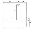
图1A和1B是具有附着于其的预制造的纳米线的衬底分别在蚀刻处理之前和在蚀刻处理之后的透视图;1A and 1B are perspective views of a substrate with prefabricated nanowires attached thereto before and after an etching process, respectively;
图2是用于执行根据本发明方法的设备的示意图;Figure 2 is a schematic diagram of an apparatus for carrying out the method according to the invention;
图3A和3B是预制造的纳米线组分别在蚀刻处理之前和在由非偏振光引发的蚀刻处理之后的顶视图;Figures 3A and 3B are top views of pre-fabricated nanowire groups before the etching process and after the etching process induced by unpolarized light, respectively;
图4A、4B和4C是预制造的纳米线组分别在蚀刻处理之前、在由线性偏振光所引发的蚀刻处理持续第一时间段之后以及在该蚀刻处理持续比第一时间段长的第二时间段之后的示意性顶视图;4A, 4B and 4C are prefabricated nanowire groups before the etching process, after the etching process induced by linearly polarized light for a first period of time, and after the etching process lasts for a second period longer than the first period of time. Schematic top view after time period;
图5A、5B和5C是预制造的纳米线组分别在蚀刻处理之前、在由沿着第一轴的线性偏振光所引发的蚀刻处理之后以及在由沿着垂直于第一轴的第二轴的线性偏振光所引发的蚀刻处理之后的示意性顶视图;5A, 5B and 5C are pre-fabricated nanowire groups before the etching process, after the etching process induced by linearly polarized light along the first axis, and after the etching process induced by linearly polarized light along the first axis. Schematic top view after etching process induced by linearly polarized light;
图6是具有含有抗蚀剂部分的表面的衬底的横截面图;Figure 6 is a cross-sectional view of a substrate having a surface containing resist portions;
图7是支撑预制造的纳米线组的衬底的示意性顶视图;Figure 7 is a schematic top view of a substrate supporting a prefabricated set of nanowires;
图8A和8B是在制造工艺第一阶段的包含预制造的纳米线组的电器件的示意性顶视图和沿图8A的线VIII-VIII的相应示意性横截面图;8A and 8B are schematic top views and corresponding schematic cross-sectional views along line VIII-VIII of FIG. 8A of an electrical device comprising a prefabricated set of nanowires at a first stage of the fabrication process;
图9A和9B是在制造工艺第二阶段的包含预制造的纳米线组的电器件的示意性顶视图和沿图9A的线IX-IX的相应示意性横截面图;9A and 9B are schematic top views and corresponding schematic cross-sectional views along line IX-IX of FIG. 9A of an electrical device comprising a prefabricated set of nanowires at a second stage of the fabrication process;
图10A和10B是在制造工艺第三阶段的包含预制造的纳米线组的电器件的示意性顶视图和沿图10A的线X-X的相应示意性横截面图;10A and 10B are schematic top views and corresponding schematic cross-sectional views along line X-X of FIG. 10A of an electrical device comprising a prefabricated set of nanowires at a third stage of the fabrication process;
图11A和11B是在制造工艺第四阶段的包含预制造的纳米线组的电器件的示意性顶视图和沿图11A的线XI-XI的相应示意性横截面图;11A and 11B are schematic top views and corresponding schematic cross-sectional views along line XI-XI of FIG. 11A of an electrical device comprising a prefabricated set of nanowires at a fourth stage of the fabrication process;
图12A和12B是在制造工艺第五阶段的包含预制造的纳米线组的电器件的示意性顶视图和沿图12A的线XII-XII的相应示意性横截面图;12A and 12B are schematic top views and corresponding schematic cross-sectional views along line XII-XII of FIG. 12A of an electrical device comprising a prefabricated set of nanowires at a fifth stage of the fabrication process;
图13是另一电器件的示意性横截面图。Fig. 13 is a schematic cross-sectional view of another electrical device.
附图未按比例绘制。通常,相同的元件由相同的参考标记表示。The figures are not drawn to scale. Generally, the same elements are denoted by the same reference signs.
在根据本发明的制造具有期望的线径的半导体纳米线组的方法中,首先提供预制造的半导体纳米线组10。可以以下列方式来获得纳米线10:In the method for manufacturing a semiconductor nanowire group with a desired wire diameter according to the present invention, firstly, a prefabricated
提供具有例如4埃的诸如Au、Ag、Pt、Cu、Fe、Ni或Co的金属的等价物的衬底20,例如由硅构成或由诸如可以具有天然氧化物的GaAs的III-V族半导体构成的晶片、或者由例如氧化铝或氧化硅制成的绝缘板,并将其放置在处于干燥炉(oven)下游端的由例如氧化铝、氧化硅、陶瓷或石墨制成的绝缘衬底固定器上。通过使用热电偶测量衬底下1mm处的衬底温度。当将具有金属膜的衬底加热到大约500摄氏度时,由金属膜形成纳米颗粒,所述纳米颗粒可以用作用于纳米线10生长的催化剂。金属膜的厚度可以在例如2和60埃之间。金属膜越厚,纳米颗粒的线径越大。在470摄氏度下加热由厚度为5埃的金构成的金属膜,获得直径为40nm的纳米线。A
将在λ=193nm的波长、100mJ每脉冲和1-10Hz的重复速率下操作的脉冲准分子激光器聚焦到靶上,该靶放置在处于干燥炉的石英管上游端的干燥炉外3-4cm处。靶可以是InP靶。或者,靶可以包括选自例如Si、Ge、InAs、GaP和GaAs的一个或多个靶。通常,材料可以是任何IV、III-V或II-VI族半导体材料。A pulsed excimer laser operating at a wavelength of λ=193 nm, 100 mJ per pulse and a repetition rate of 1-10 Hz was focused onto a target placed 3-4 cm outside the drying oven at the upstream end of the quartz tube of the drying oven. The target may be an InP target. Alternatively, the target may comprise one or more targets selected from, for example, Si, Ge, InAs, GaP, and GaAs. In general, the material can be any Group IV, III-V or II-VI semiconductor material.
将靶材料蒸发并传送到衬底20上。这导致纳米线10在由金属膜形成的纳米颗粒的催化作用下的生长。当衬底温度处于450-500℃的范围内时生长InP纳米线。温度越高,所生长的纳米线的线径越大。在500℃以上的温度下,可以形成InP纳米管,即具有空心的纳米线。生长期间的压力在100-200mbar的范围内,并且施加在100-300sccm之间的氩气流。当时加15000个激光脉冲时,纳米线的长度可以为例如2-10微米。分别采用较少和较多的激光脉冲可以获得较短和较长的纳米线。最终的线径由金属膜的厚度以及生长期间的衬底温度来决定。可以以例如0.001-1.0mol%的浓度添加掺杂剂以获得n型和/或p型InP纳米线。n型掺杂剂可以包括例如S、Se和Te,p型掺杂剂可以包括例如Zn。可以将掺杂剂添加到由准分子激光器照射的靶中,或者可以将其作为气体提供给干燥炉,而与靶的照射无关。纳米线中有效掺杂剂的最终水平为1017-1020原子/cm3。在生长工艺期间,例如通过将激光束转移到另一个靶上,例如选自上述靶中的一个,可以在布线中建立结,即p-n结和/或异质结。The target material is evaporated and transferred onto the
由此获得的预制造的半导体纳米线10由图1A所示的衬底20来支撑。至少一个预制造的半导体纳米线10’具有大于期望的线径d的线径d’。线径d’可以归因于两个或多个纳米颗粒在纳米线10生长期间的集合,和/或归因于淀积太厚的金属膜,和/或归因于在纳米线10合成期间的高温。The
衬底20可以是电导体,例如p掺杂或n掺杂的硅晶片。可以将预制造的半导体纳米线10导电连接到衬底20。为此,可以将金属膜淀积在不具有天然氧化膜的衬底20上。当在无氧气氛中形成用作催化剂的纳米颗粒和纳米线10时,可以将纳米线10导电连接到衬底20。
随后,通过蚀刻来减小至少一个预制造的纳米线10’的线径。为此,通过将0.1-20vol.%例如2.5vol.%的HF和20-200g/l例如62.5g/l的氧化三辛基膦(trioctylphosphideoxide)(TOPO)添加到诸如1-丁醇、戊醇、丙醇或乙醇的醇样品中,来制备蚀刻溶液。取代或除TOPO之外,可以使用三辛基膦(trioctylphosphide)(TOP)。TOP和TOPO的总量可以在20-200gl之间。将例如为20μl的由此获得的蚀刻溶液21的液滴滴掷到具有预制造的纳米线10的衬底20上。可以将图2所示的玻璃或特氟纶涂敷板22放置在液滴的顶部以避免溶液的蒸发。板22可以由未示出的支撑体结构来支撑,以获得蚀刻液体22的精确限定厚度。Subsequently, the diameter of at least one prefabricated nanowire 10' is reduced by etching. For this purpose, by adding HF of 0.1-20 vol.%, for example 2.5 vol.%, and 20-200 g/l, for example 62.5 g/l of trioctylphosphine oxide (TOPO) to e.g. 1-butanol, pentanol , propanol or ethanol alcohol samples to prepare etching solutions. Instead of or in addition to TOPO, trioctylphosphide (TOP) may be used. The total amount of TOP and TOPO can be between 20-200gl. A drop of the
通过使与蚀刻溶液接触的纳米线10经受光照,来蚀刻纳米线10。纳米线10的蚀刻由其所吸收的光来引起。选择光谱使得当至少一个预制造的纳米线10’到达期望的线径d时显著减小该至少一个预制造的纳米线10’的吸收。对于6、10、30、44和60nm的InP纳米线所期望的线径,最小波长分别大约为760、820、870、890和905nm。大量(bulk)InP的发射是在λ=920nm下。The
光引发蚀刻的自行终止归因于量子局限,其限制对如上所述的某些线径以下的光的吸收。图1B所示出的在该蚀刻处理之后的结果是预制造的纳米线10’具有期望的线径d。The self-termination of photoinduced etching is due to quantum confinement, which limits the absorption of light below certain line diameters as described above. The result after this etching process shown in Figure IB is a prefabricated nanowire 10' having the desired wire diameter d.
在一个实施例中,在减小线径的步骤之前,基本上所有预制造的纳米线10’的直径d’大于或等于期望的线径d。为此,用于形成催化剂纳米颗粒的金属膜可以相对较厚,使得基本上所有预制造的纳米线的线径大于期望的线径。在执行蚀刻处理之后,基本上所有的纳米线具有期望的线径d。术语“基本上所有的预制造的纳米线”和“基本上所有的纳米线”意味着将纳米线10’的预制造设计成产生具有大于期望直径d的直径d’的纳米线。由于偶然不期望地由金属膜形成一个或一些纳米颗粒,而使一个或一些纳米线会具有意外地小于期望的线径d的线径d’。In one embodiment, prior to the wire diameter reducing step, substantially all of the prefabricated nanowires 10' have a diameter d' greater than or equal to the desired wire diameter d. To this end, the metal film used to form the catalyst nanoparticles can be relatively thick such that substantially all of the prefabricated nanowires have a wire diameter larger than desired. After performing the etching process, substantially all nanowires have the desired wire diameter d. The terms "substantially all of the prefabricated nanowires" and "substantially all of the nanowires" mean that the prefabrication of the nanowires 10' is designed to produce nanowires with a diameter d' greater than the desired diameter d. One or some nanowires may have a wire diameter d' that is unexpectedly smaller than the desired wire diameter d due to the occasional undesired formation of one or some nanoparticles from the metal film.
对于光引发的蚀刻,可以使用在图2中示意性示出的设备29。该设备包括用于照射预制造的纳米线10的光源30,其例如可以为HgXe灯。该光源的光可以是非偏振的。于是可以同时蚀刻大面积的具有预制造的纳米线10的衬底20。光源30发射用于引发蚀刻的光谱。当蚀刻InP纳米线并以10nm的期望的线径为目标时,光谱具有820nm的最小波长。光源还发射其他在820与254nm之间的波长。具有其他波长的光源能够引发具有期望的线径d的预制造半导体纳米线10的蚀刻。为了大大减小对具有期望的线径d的纳米线10的蚀刻,通过滤波器31对由光源30发射的光进行光谱滤波,以在引发蚀刻之前充分减少具有其他波长的光。可以使用长通滤波器、诸如干扰滤波器的带通滤波器和/或单色器来基本上防止对具有期望的线径的纳米线的蚀刻。应用适当的滤波器,对纳米线进行尺寸选择性地光蚀刻以降至期望的线径。蚀刻工艺通常用去2-10小时。或者,使用激光器作为光源30。激光器的激光束可以被线性偏振,由此引发蚀刻处理的光沿着轴被线性偏振。激光器可以是可调激光器,例如二极管激光器或钛蓝宝石激光器。For photo-induced etching, the
可以通过物镜33将光源30的光聚焦到具有预制造的纳米线10的衬底20上。引发蚀刻的光的功率密度取决于所使用的物镜的放大倍率。放大倍率例如可以在50至1000x之间。在457nm的波长下,功率密度可以在0.5与10kW/cm2之间。例如通过偏振斜方六面体使偏振向量旋转。针对InP纳米线获得的最大激发偏振率为0.95。在光蚀刻3-120分钟之后,通常会观察到蓝色偏移和/或光致发光的强度增加。所获得的发射强度的最大增加为倍数1300。The light of the
在使预制造的纳米线经受蚀刻溶液之前,可以使纳米线经受20vol.%的HF水溶液,其可以除去纳米线外表面处的氧化物。这种处理可以减小通过光引发的蚀刻处理来减小线径所需要的处理时间。Before subjecting the prefabricated nanowires to the etching solution, the nanowires can be subjected to a 20 vol.% aqueous solution of HF, which can remove oxides at the outer surface of the nanowires. This process can reduce the processing time required to reduce the wire diameter by photo-induced etching process.
在蚀刻工艺期间,例如由于表示线径的光致发光(photo luminescence),而使纳米线可以发射光信号。可以通过监控器单元35来监测发光强度以及发光波长,所述监控器单元35可以提供与光致发光的强度相关的信号和/或与光致发光的波长相关的信号。可以根据由监控器单元35提供的一个或两个信号来控制光源30。例如,当监控器单元35提供表示光致发光具有预定的光谱组成的信号时,可以阻挡光源。当利用光引发蚀刻工艺的自行终止时,这允许减小并且优选避免在纳米线具有期望的线径之后的不必要的曝光和工艺时间。为此,可以将监控器单元35和光源30连接到诸如计算机的系统控制单元36。在图2所示的实施例中,由监控器单元35检测到的光由物镜33收集并通过光束分裂器37将其与引发蚀刻的光分离。光束分裂器37可以是在光致发光的波长下反射并在引发蚀刻的光的波长下透明的二向色镜。During the etching process, the nanowires may emit light signals, for example due to photoluminescence indicative of the wire diameter. The luminescence intensity as well as the luminescence wavelength can be monitored by a
在一个实施例中,不是通过由于量子局限而不再吸收光的这一事实来终止光引发的蚀刻。而是当纳米线具有期望的线径d时终止蚀刻,在该线径d下,仍吸收引发蚀刻的光。为了在蚀刻期间控制线径d,例如通过监控器35来监测由纳米线10发射的光,并且根据由纳米线10所发射的光的光谱组成和/或强度,来终止引发蚀刻的光的施加。为此,可以通过未示出的遮光器来切断或阻挡光源30。In one embodiment, photo-induced etching is not terminated by the fact that light is no longer absorbed due to quantum confinement. Instead, etching is terminated when the nanowire has a desired wire diameter d, at which the light that initiated the etching is still absorbed. In order to control the wire diameter d during etching, the light emitted by the
该方法是基于这样的理解:在光引发的蚀刻期间由纳米线10发射的光表示被蚀刻的纳米线组的线径d。纳米线10越薄,由纳米线发射的光更多地偏向蓝。因此,通过在蚀刻期间监测由纳米线10发射的光的波长,可以确定必须停止光施加以便获得期望的线径的时刻。The method is based on the understanding that the light emitted by the
在一个实施例中,提供一组随机取向的预制造的纳米线10。例如可以通过以下方式中的一种获得该组:可以在具有纹理表面的衬底20上生长纳米线10,部分的纹理表面具有随机的取向。这会导致随机取向的纳米线10。或者,可以通过超声波或通过在机械上去除掉纳米线10而使纳米线10与衬底20分离并且可以将所述纳米线10分散在溶剂中。可以将纳米线10溶解在例如任意的烷烃或烷醇C2-C12的溶剂中。可以根据本发明的方法通过照射包含溶液中的纳米线的容器来蚀刻纳米线。容器和溶剂对于引发蚀刻的光来说至少部分透明。容器和溶剂对于用于表示线径的光信号来说可以至少部分透明。容器可以具有包含玻璃或石英的壁。In one embodiment, a set of randomly oriented
可以通过滴掷将包含纳米线10的溶液淀积在衬底20上。可以利用流动组装(flow assembly)或电场对准来至少部分地确定纳米线的方向。The solution containing the
在一个实施例中,提供在图3A中示意性示出的一组随机取向的预制造的纳米线10。至少一个预制造的纳米线10’具有大于期望的线径d的线径d’。当提供该组时,该组可以包括一个或多个具有期望的线径d的纳米线10。在一个实施例中,图3A所示的在蚀刻处理前的预制造的纳米线组具有相对较宽的线径的分布。或者,在蚀刻处理之前提供的预制造的纳米线组具有相对较窄的线径的分布,如图4A所示。通过利用例如HeXe灯的非偏振光的光引发蚀刻,来处理图3A所示的预制造的纳米线组10。用于引发蚀刻的光的光谱具有最小波长λ,选择该最小波长使得光引发的蚀刻处理在期望的线径d下自行终止。或者,可以使用波长短于λ的光并且当用于表示线径的光信号表示纳米线组具有期望的线径时,终止蚀刻工艺。在图3B中示意性地示出由具有最小波长λ的光引发的蚀刻结果,其中选择所述最小波长λ使得光引发的蚀刻处理在期望的线径下自行终止:在光引发的蚀刻处理之后,纳米线组具有相对较窄的线径的分布。基本上所有的纳米线10具有期望的线径d,而与纳米线10的取向无关。In one embodiment, a set of randomly oriented
可以例如沿着在图4A与4B和4C之间示意性示出的轴40对引发蚀刻的光进行线性偏振。在一个实施例中,图4A所示的在蚀刻处理之前所提供的预制造的纳米线组10具有相对较窄的线径的分布。或者,在蚀刻处理之前所提供的预制造的纳米线组可以具有相对较宽的线径的分布,如图3A所示。利用线性偏振光来对图4A所示的预制造的纳米线组10进行光引发的蚀刻处理,其中可以通过诸如激光器的光源在该偏振状态下发射该线性偏振光,或者通过利用发射非线性偏振光例如非偏振光的光源,例如HeXe灯以及本例中的线性偏振器39,来获得该线性偏振光。甚至当例如由于光源30的偏振方向尽管不垂直于期望的偏振方向但也与其不同,和/或由于光源30的偏振比率较低而使光源30发射偏振光时,设备29也可以包括图2所示的偏振器39。如果存在,偏振器39可以位于光源30与滤波器31之间,如图2所示。或者,偏振器39和滤波器31可以互换,例如当滤波器31的传输取决于偏振方向时这可能是有利的。可以通过图2所示的且本领域公知的光学元件38,例如半拉姆达板或相互倾斜的镜的组合,来旋转引发蚀刻的光的偏振方向以获得沿着轴40的期望偏振。Light that initiates etching may be linearly polarized, for example, along axis 40 shown schematically between Figures 4A and 4B and 4C. In one embodiment, the prefabricated nanowire set 10 shown in FIG. 4A provided before the etching process has a relatively narrow distribution of wire diameters. Alternatively, the prefabricated nanowire set may be provided with a relatively broad distribution of wire diameters prior to the etching process, as shown in FIG. 3A . Photoinduced etching of the
通过纳米线10的线性偏振光的吸收取决于它们的取向:其纵轴平行于轴40的纳米线10相对有效地吸收光,其中使光沿着轴40偏振,而其纵轴垂直于轴40的纳米线10相对无效地吸收光。蚀刻效率取决于光的吸收。光子吸收得越多,蚀刻就越有效。因此,由线性偏振光引发的蚀刻是各向异性的,即,它们的纵轴平行于轴40的纳米线10被相对有效地蚀刻,而其纵轴垂直于轴40的纳米线10被相对无效地蚀刻。The absorption of linearly polarized light by
在光引发的蚀刻处理之后,那些其纵轴平行于轴40的纳米线10a具有期望的线径d,而那些其纵轴垂直于轴40的纳米线10b基本上未被有效地蚀刻,即,在蚀刻处理之后,它们的线径db基本上与蚀刻处理前相同,参见图4B。对于由参考标记10c和10d示例性示出的其纵轴即不平行又不垂直于轴40的纳米线,吸收效率在这两种极端之间。通常,吸收效率与纳米线10的纵轴与轴40之间的角度的三角函数成比例。结果,在蚀刻期间,这些具有中间位置的纳米线的线径被减小,比较初始线径dc’和dd’与图4B中的线径dc和dd。线径的减小取决于纵轴相对于轴40的取向。当平行于轴40的纳米线10a具有期望的线径d时,会停止光引发的蚀刻。可以通过监测用于表示线径的光信号来确定停止蚀刻处理的时刻。当该光信号包括用于表示期望的线径的分量时,会停止蚀刻处理。After the photo-induced etching process, those
在光引发的蚀刻处理之后,在图4B中示意性示出的纳米线组10具有相对较宽的线径的分布,而在光引发的蚀刻处理之前,在图4A中示意性示出的纳米线组10具有相对较小的线径的分布。纳米线10的线径取决于纳米线10的取向。After the photo-induced etching process, the
用于引发蚀刻的线性偏振光的光谱可以具有最小波长λ,选择该最小波长λ使得光引发的蚀刻处理在期望的线径d下自行终止。或者,可以使用波长短于λ的光,并且当用于表示线径的光信号表示纳米线组中的至少一些具有期望的线径d时,会终止蚀刻工艺。The spectrum of linearly polarized light used to initiate etching may have a minimum wavelength λ chosen such that the photo-induced etching process terminates itself at the desired wire diameter d. Alternatively, light with a wavelength shorter than λ may be used and the etching process may be terminated when the optical signal indicative of the wire diameter indicates that at least some of the set of nanowires have the desired wire diameter d.
当引发蚀刻处理的光具有被选择成使得光引发的蚀刻处理在期望的线径d下自行终止的最小波长λ时,可以在到达在图4B中示意性示出的状态时继续光引发的蚀刻处理。由于平行于轴40的纳米线10a具有期望的线径d,所以它们不再相对有效地吸收引发蚀刻的光。结果,它们基本上未被有效地蚀刻。它们可以根本上不被有效地蚀刻。由于垂直于轴40的纳米线10b也不相对有效地吸收引发蚀刻的光,所以它们也基本上未被有效地蚀刻。它们可以根本上不被有效地蚀刻。具有中间取向的纳米线10c、10d被相对有效地蚀刻,直到它们达到期望的线径d,在该期望的线径d下,大大地减小引发蚀刻的光的吸收并由此大大减小蚀刻的效率。由此获得的纳米线组在图4C中示意性地示出。When the light initiating the etching process has a minimum wavelength λ selected such that the photo-induced etching process terminates itself at the desired line diameter d, the photo-induced etching can be continued upon reaching the state schematically shown in FIG. 4B deal with. Since the
除了以上说明的且还被称为第一分量的线性偏振光之外,可以通过引发蚀刻处理的光的第二分量来照射随机取向的预制造的纳米线组。第二分量可以沿着垂直于第一轴的第二轴被线性偏振,所述第一轴例如平行于图4A-4C中示出的纳米线10b的纵轴。该第二分量可以引发纳米线10b的相对有效的蚀刻,利用第一分量蚀刻该纳米线10b相对无效。第一分量可以包含具有第一最小波长λ1的第一光谱,而第二分量可以包含具有与第一最小波长λ1不同的第二最小波长λ2的第二光谱。第一最小波长λ1和第二最小波长λ2可以分别对应于例如1.6和2.0eV的能量。平行于其带隙在本例中小于2.0eV的第二轴的纳米线吸收第二分量并且由此被蚀刻直到它们在本例中具有2.0eV的带隙。以这种方式,垂直于轴40的纳米线也可以被有效地蚀刻到期望的线径,该期望的线径可以与由第一最小波长λ1确定的期望的线径d不同。In addition to the linearly polarized light explained above and also referred to as the first component, the randomly oriented prefabricated nanowire groups can be illuminated by a second component of light that induces the etching process. The second component may be linearly polarized along a second axis perpendicular to a first axis, for example parallel to the longitudinal axis of the
可以同时、依次、或部分同时和部分依次地施加第一分量和第二分量。The first and second components may be applied simultaneously, sequentially, or partially simultaneously and partially sequentially.
当第二最小波长λ2与第一最小波长λ1不同时,色调调和(tone)可以以具有超出最大期望的线径的线径的纳米线开始。When the second minimum wavelengthλ2 is different from the first minimum wavelengthλ1 , a tone may start with nanowires having wire diameters that exceed the maximum desired wire diameter.
第一分量可以具有第一强度而第二分量可以具有与第一强度不同的第二强度。由于时刻处理的效率取决于由被蚀刻的纳米线所吸收的光的数量,并且由于对于偏振光、该数量取决于纳米线的取向,所以纳米线可以被各向异性地蚀刻,即取决于它们的取向。这可以在第二最小波长λ2不同于第一最小波长λ1时以及在他们相等时实现。The first component may have a first intensity and the second component may have a second intensity different from the first intensity. Since the efficiency of the instant process depends on the amount of light absorbed by the etched nanowires, and since for polarized light this amount depends on the orientation of the nanowires, the nanowires can be etched anisotropically, i.e. depending on their orientation. This can be achieved when the second minimum wavelengthλ2 is different from the first minimum wavelengthλ1 as well as when they are equal.
根据本发明的方法可以用于从预制造的纳米线组中除去一个或多个纳米线。在这种情况下,各纳米线的期望的线径包括零。为此,具有大约2.4eV或以上能量的光子的光可以用于InP。引发对期望的线径为零的纳米线进行蚀刻的光可以被线性偏振。The method according to the invention can be used to remove one or more nanowires from a prefabricated set of nanowires. In this case, the desired diameter of each nanowire includes zero. To this end, light with photons having an energy of about 2.4 eV or more can be used for InP. The light that initiates etching of the desired zero diameter nanowire can be linearly polarized.
图5A所示的在蚀刻处理之前所提供的预制造的纳米线组包括基本上水平的纳米线10h、基本上垂直的纳米线10v以及处于中间、即既不基本平行也不基本垂直的纳米线10i。当通过具有相对较短的波长的光照射该组,使得由纳米线吸收光直到它们破碎时,可以从该组中除去纳米线。The prefabricated set of nanowires provided prior to the etching process shown in FIG. 5A includes substantially
在图5A和5B的例子中,光沿着轴40被线性偏振,即它被垂直偏振。在这种情况下,基本上平行于轴40的纳米线10v相对有效地吸收光并且可以将其从该组中除去,而基本上垂直于轴40的纳米线10h相对较无效地吸收光。因此,不将它们从该组中除去。是否从该组中除去处于中间的、即既不基本水平也不基本垂直的纳米线10i取决于照射的持续时间。当在除去最后一个基本垂直的纳米线10v之后就立即终止照射时,纳米线10i可以保留。当继续照射时,它们也会被除去。在这种情况下照射持续得越长,剩余的纳米线10h的取向被限定得越好。In the example of Figures 5A and 5B, the light is linearly polarized along axis 40, ie it is vertically polarized. In this case,
在图5A和5C的例子中,光沿着垂直于轴40的轴41被线性偏振,即它被水平偏振。在这种情况下,基本上平行于轴41的纳米线10h相对有效地吸收光并且可以将其从该组中除去,而基本上垂直于轴41的纳米线10v相对较无效地吸收光。因此,不将它们从该组中除去。是否从该组中除去处于中间的、即既不基本水平也不基本垂直的纳米线10i取决于照射的持续时间。当在除去最后一个基本垂直的纳米线10h之后就立即终止照射时,纳米线10i可以保留。当继续照射时,它们也会被除去。在这种情况下照射持续得越长,剩余的纳米线10v的取向被限定得越好。In the example of Figures 5A and 5C, the light is linearly polarized along
当由衬底20支撑预制造的纳米线10时,在蚀刻处理期间,衬底20可以具有表面23,其由支撑预制造的半导体纳米线10的部分23a和在部分23a之外的另外部分23b构成,至少是该另一部分23b。衬底20可以是同质的并且完全由作为抗蚀剂的材料例如特氟纶构成。衬底20可以包括:不作为抗蚀剂的第一层24,例如硅晶片上的天然氧化物层;以及作为抗蚀剂的第二层25,图6所示的第二层25构成表面23的另一部分23b。通过化学键将第二层25连接到第一层24,该化学键在这两层之间产生相对较强的互连,并因此导致对第一层24的相对有效的保护。第二层25可以由选自烷基三乙氧基硅氧烷和烷基三甲氧基硅氧烷的一种或多种材料例如氨基丙基三乙氧基硅氧烷(APTES)构成。烷基可以是丙烷基(C3)、丁基(C4)、戊基(C5)直到C12。氨基可以由巯基或羧基来代替。When the
在一个实施例中,具有由层24构成的非抗蚀剂表面的衬底20,如具有例如天然氧化物的硅晶片,设置有金属膜以产生用作用于上述纳米线生长的催化剂的纳米颗粒。在纳米线10生长之后,具有纳米线的衬底20的表面23设置有是APTES的第二层25。将支撑预制造的纳米线的衬底在0.5%APTES在乙醇的溶液中浸入10分钟。第二层25选择性地结合,即它与构成第一层24的氧化物结合而不与由InP或任何其他的除硅之外的半导体构成的纳米线10结合。最终的结构在图6中示出。In one embodiment, a
在该实施例中,提供预制造的半导体纳米线的步骤包括提供可以具有第一层24的衬底20的子步骤。至少衬底20的一部分不是抗蚀剂。在衬底20的表面23a上生长半导体纳米线10。由此生长的半导体纳米线是预制造的半导体纳米线10。在提供预制造的半导体纳米线10的步骤之后并在通过如上所述的蚀刻来减小所述至少一个预制造的纳米线10的线径的步骤之前,利用抗蚀剂层25覆盖衬底20的表面23的部分23b。In this embodiment, the step of providing pre-fabricated semiconductor nanowires comprises the sub-step of providing a
在另一实施例中,通过提供具有作为第一层24的天然氧化物的硅晶片来形成衬底20。然后,第一层24被设置有由APTES构成的第二层25。随后,通过滴掷包含纳米线10的液体溶液来提供预制造的纳米线10,如上所述。In another embodiment,
当预制造的纳米线10由衬底20支撑并分布在衬底20的表面23上时,由用于引发蚀刻处理的光来照射表面的第一部分18,而表面中在第一部分18之外的第二部分19不被照射。以这种方式,不蚀刻第二部分19中的纳米线,而蚀刻第一部分18中的纳米线。结果,在蚀刻处理之后表面23的第一部分18中的纳米线具有期望的线径,而第二部分19中的纳米线仍具有它们初始的线径。可以通过由光引发的蚀刻来除去第一部分18中的纳米线10。When the
在一个实施例中,由第一光强度照射表面23的第一部分18,而由小于第一光强度的第二光强度照射第二部分19。结果,与第二部分19中的纳米线相比,第一部分18中的纳米线被更加有效地蚀刻。当在第二部分19中的纳米线的蚀刻自行终止之前例如通过阻挡光源30来停止光引发的蚀刻处理时,第一部分18中的纳米线10获得比第二部分19中的纳米线小的线径。In one embodiment, the first portion 18 of the
第一部分18中的纳米线的蚀刻可以自行终止或可以在达到使蚀刻自行终止的线径之前使其停止。在后一种情况下,可以根据用于表示线径的光信号来阻挡光源30。Etching of the nanowires in the first portion 18 may be self-terminating or may be stopped before reaching a wire diameter for etching to be self-terminating. In the latter case, the
可以通过掩模来限定可以不被照射或可以利用第二强度照射的第一部分18和第二部分19。掩模可以是设备29的分离部件。可以将掩模集成在滤波器31和/或板22中。当不照射部分19时,掩模阻挡射向第二部分19的光。当利用小于第一强度的第二强度来照射部分19时,掩模部分阻挡射向第二部分19的光。掩模可以是抗蚀剂并且可以在提供蚀刻溶液之前直接将其设置到第二部分19。取代掩模,可以提供光作为例如在表面23上进行扫描的聚焦光斑。可以调整扫描速度以改变有效的强度,即其中扫描速度相对较低的区域被相对有效地蚀刻,而其中扫描速度相对较高的区域被相对无效地蚀刻。或者,在扫描期间可以在作为位置的函数的强度和/或最小波长方面调制光。为此,设备可以包括由系统控制单元控制的扫描单元。The first portion 18 and the second portion 19 which may not be illuminated or which may be illuminated with the second intensity may be defined by a mask. The mask may be a separate component of
在一个实施例中,可以由具有第一最小波长的光照射表面23的第一部分18,可以由具有与第一最小波长不同的第二最小波长的光照射表面23中在第一部分18之外的第二部分19。以这种方式,可以将第一部分18中和第二部分19中的纳米线蚀刻到分别由第一最小波长和第二最小波长确定的不同的期望的线径。In one embodiment, the first portion 18 of the
当利用具有不同最小波长的光照射第一部分18和第二部分19时,可以依次照射第一部分18和第二部分19。当分别蚀刻第二部分19和第一部分18时,掩模可以用于阻挡射向第一部分18和第二部分19的光。该掩模可以类似于上述用于照射第一部分18而不照射第二部分19的掩模。或者,可以使用被构图的滤波器31,其具有用于传输具有第一最小波长的光的第一区域和用于传输具有第二最小波长的光的第二区域。将第一区域和第二区域设计成使得它们分别将光传输到第一部分18和第二部分19。When the first portion 18 and the second portion 19 are irradiated with light having different minimum wavelengths, the first portion 18 and the second portion 19 may be sequentially irradiated. The mask may be used to block light from the first portion 18 and the second portion 19 when the second portion 19 and the first portion 18 are respectively etched. The mask may be similar to the mask described above for illuminating the first portion 18 without illuminating the second portion 19 . Alternatively, a patterned
在制造电器件100的方法中可以使用根据本发明的纳米线组的制造方法。电器件100包括具有期望的线径的纳米线组10。电器件100可以包括各自电连接到第一导体110和第二导体120的纳米线10,第二导体120可以与第一导体110电绝缘。The manufacturing method of the nanowire group according to the present invention may be used in the method of manufacturing the
电器件100可以包括纳米线组10,该组包括:纳米线的第一子组10a,其各自具有第一线径da;以及纳米线的第二子组10b,其各自具有与第一线径da不同的第二线径db。可以将第一子组的纳米线10a附着到衬底20的第一部分,其在图8A-12B的例子中由第一导体110a构成。可以将第二子组的纳米线10b附着到衬底20的第二部分,其在图8A-12B的例子中由第一导体110b构成并且在第一部分之外。The
可以将第一子组的纳米线10a电连接到导体,其在图8A-12B的例子中由第一导体110a构成。可以将第二子组的纳米线10b电连接到另一导体,其在图8A-12B的例子中由第一导体110b构成并且与所述另一导体电绝缘。The first subset of
该方法包括以下步骤:根据上述方法的实施例制造具有期望的线径的半导体纳米线组10,并使其与第一导体110和第二导体120电接触。在图8A-12B中示出该方法的连续步骤。The method includes the following steps: manufacturing the
在第一步骤中,可以为硅晶片的衬底20设置有隔离区102,其可以是图8A和8B所示的浅沟槽绝缘(STI)区域,并且衬底20设置有第一导体110,其用于电接触稍候将要形成的纳米线10。可以通过掺杂衬底在STI区域之外的区域来形成第一电导体110。或者,可以淀积导体用于形成第一导体110。衬底20可以是诸如石英衬底的绝缘体。在这种情况下,不需要隔离区102。在图8A-12B的实施例中,提供三个平行的、相互绝缘的第一导体110。然而,本发明不限于三个互相绝缘的第一导体110。或者,可以将第一导体110导电连接到该组的所有纳米线10,或其可以包括N个相互电绝缘的导体,其中N是大于1的整数。这里以及在本申请的剩余部分中,术语“相互电绝缘”意味着不直接地使导体电连接。它并不排除间接地使导体电连接,即通过一个或多个附加的元件,例如纳米线10和/或第二导体120,使导体电连接。衬底20对于可见光可以是透明的。In a first step, the
可以将由诸如金的金属构成的纳米颗粒111设置到第一导体110上,所述纳米颗粒111可以用作用于生长纳米线10的催化剂,例如如上所述。在相应的纳米颗粒111的位置上生长纳米线10。图9A和9B所示的由此获得的预制造的纳米线10’中的至少一个的线径d’可以大于期望的线径d。为了减小其线径大于期望的线径d的那些纳米线10’的线径d’,对纳米线进行根据本发明的光引发的蚀刻处理。在生长纳米线10’之后并且在提供蚀刻溶液之前,预制造的电器件100可以设置有诸如APTES的抗蚀剂层,以保护STI区域,如果其存在的话,和/或衬底。
为了引发对图10A和10B所示的附着到第一导体110a的纳米线10a的蚀刻处理,可以使用具有第一最小波长的光来产生期望的线径da。在对附着到第一导体110a的纳米线10a进行该蚀刻处理期间,例如通过利用掩模可以防止分别对附着到第一导体110b和110c的纳米线10b和10c进行蚀刻。随后,通过利用具有第二最小波长的光的光引发蚀刻,可以对图10A和10B所示的附着到第一导体110c的纳米线10c进行蚀刻,产生期望的线径dc。在对附着到第一导体110c的纳米线10c进行该蚀刻处理期间,例如通过利用掩模可以防止分别对附着到第一导体110a和110b的纳米线10a和10b进行蚀刻。如果需要,也可以对附着到第一导体110b的纳米线10b进行蚀刻以获得期望的线径db。如果相关,纳米线10a、10b、以及10c的蚀刻可以自行终止或可以根据用于表示线径的光信号而使其终止。To induce the etching process of the
在该方法中,获得一组纳米线10a、10b、10c,其由三个纳米线子组构成,每个子组具有与其他两个子组的纳米线的线径不同的线径。将每个子组连接到特定的第一导体110a、110b、110c。In this method, a set of
随后,图10A和10B所示的预制造的电器件100可以设置有图11A和11B所示的优选为透明的电介质层130,例如旋涂玻璃(SOG)。由此获得的预制造的电器件100的上表面设置有用于电接触纳米线10的上端部分的第二导体120。Subsequently, the prefabricated
可以将纳米线10a、10b、10c的上端部分电连接到图12A和12B所示的相互电绝缘的第二导体120a、120b、120c。第一导体110a、110b和110c与第二导体120a、120b和120c相互垂直,并在本例中形成三乘三阵列。在图8A-12B的实施例中,将一个纳米颗粒111并由此将一个纳米线10设置在由第一导体110和第二导体120限定的每个交叉区域处,所述第一导体110和第二导体120在本例中限定矩形的三乘三阵列。本发明不限于该形状或尺寸的阵列。本发明不限于每一个交叉区域仅有一个纳米颗粒111和一个纳米线10。而是一些或所有的交叉区域可以具有一个以上的纳米颗粒111和一个纳米线10。Upper end portions of the
对于可见光第二导体120a、120b、120c可以至少部分透明。它们例如可以由氧化铟锡(ITO)构成。第一导体110和/或第二导体120可以由锌或锌合金构成。The
纳米线10a、10b、10c可以各自包括图13所示的形成p-n结的p掺杂部分10p和n掺杂部分10p。当将电流从第一导体110经由纳米线10发送到第二导体120时,从各n掺杂部分10n和p掺杂部分10p中注入电子和空穴。当这些电荷载流子复合时,发射出光。由于与空穴相比,电子的迁移率更高,所以主要在接近于p-n结的p掺杂部分10p中发光。The
在图12A和12B所示的电器件100中,纳米线10a、10b和10c可以各自包括p-n结。通过空穴和电子的上述复合发射的光的波长取决于带隙,并且因此取决于在复合位置上的线径。在图12A和12B的实施例中,纳米线10a、10b和10c可以具有不同的线径da、db和dc,因此它们可以发射不同波长的光。纳米线可以由InP构成,而且n掺杂部分10n例如由S、Se和/或Te掺杂,并且p掺杂部分10p例如由Zn或Cd掺杂。掺杂剂的浓度例如可以在1017-1020cm-3之间。In the
p-n结可以用作选择器件,即由第一导体110和第二导体120形成的阵列中的像素可以通过对相应的第一导体110和第二导体120施加偏压来进行选择。位于第一导体110b和第二导体120b的交叉处的纳米线10bb可以通过对这两个导体施加偏压来进行选择。在交叉处可以定位和选择一个以上的纳米线10bb。The p-n junction can be used as a selection device, ie a pixel in the array formed by the
或者,电器件100可以包括诸如晶体管的选择器件的阵列,所述晶体管可以是薄膜晶体管并且可以集成在衬底中。通过用于选择纳米线10的子组的选择线的栅格来对选择器件进行寻址。Alternatively,
在图13所示的实施例中,将n掺杂部分10n电连接到离p-n结具有第一距离ln的第一导体110。P掺杂部分10p电连接到离p-n结具有第二距离lp的第二导体120,第二距离lp小于第一距离ln。n掺杂部分10n具有大于p掺杂部分10p的线径dp的线径dn。In the embodiment shown in Figure 13, the n-doped portion 10n is electrically connected to the
由于p-n结的存在,而使由对引发蚀刻的光的吸收所产生的电子空穴对分离,使得电子流向n掺杂部分10n而空穴流向p掺杂部分10p。空穴主要负责光引发的蚀刻。p掺杂部分10p中的较高空穴浓度导致更高效的蚀刻,并且因此导致相对较小的线径dp。结果,纳米线具有两个区域,分别为具有不同的直径dn和dp的n掺杂部分10n和p掺杂部分10p。n掺杂区可以具有与蚀刻前的线径相似的直径。可以通过用于引发蚀刻的光的最小波长来预先确定p掺杂部分10p的线径dp。当蚀刻具有n掺杂部分10n和p掺杂部分10p的纳米线10时,可以观察到用于表示线径的光信号。由于p掺杂部分10p中的电子和空穴的复合而发射的光用于表示该部分的线径dp。一旦光信号表示达到期望的线径dp,则可以阻挡引发蚀刻的光以防止对n掺杂部分的任何进一步的蚀刻,该蚀刻会导致不希望出现的n掺杂部分10n的线径dn的进一步减小。Due to the existence of the p-n junction, the electron-hole pairs generated by the absorption of the light inducing the etching are separated, so that the electrons flow to the n-doped portion 10n and the holes flow to the p-doped portion 10p. Holes are mainly responsible for photo-induced etching. A higher hole concentration in the p-doped portion 10p results in more efficient etching and thus a relatively smaller wire diameter dp. As a result, the nanowire has two regions, an n-doped portion 10n and a p-doped portion 10p with different diameters dn and dp, respectively. The n-doped region may have a diameter similar to the wire diameter before etching. The line diameter dp of the p-doped portion 10p can be predetermined by the minimum wavelength of light used to induce etching. When the
应该注意的是,上述实施例是对本发明进行举例说明,而非限制本发明,并且本领域技术人员在不脱离所附权利要求书的范围下能够设计出许多可选实施例。在权利要求书中,任何放置在括号内的参考标记不应该被认为是限制本发明。词“包括”不排除在权利要求中所列的那些元件或步骤之外的其他元件或步骤的存在。元件之前的词“一个”不排除多个这种元件的存在。It should be noted that the above-mentioned embodiments illustrate rather than limit the invention, and that those skilled in the art will be able to design many alternative embodiments without departing from the scope of the appended claims. In the claims, any reference signs placed between parentheses shall not be construed as limiting the invention. The word "comprising" does not exclude the presence of other elements or steps than those listed in a claim. The word "a" or "an" preceding an element does not exclude the presence of a plurality of such elements.
制造具有期望的线径d的半导体纳米线组10的方法包括以下步骤:提供预制造的半导体纳米线组10’,至少一个预制造的半导体纳米线具有大于期望的线径d的线径d’,并且通过蚀刻来减小该至少一个预制造的纳米线10’的线径;由被该至少一个预制造的纳米线10’所吸收的光来引发该蚀刻,选择光的光谱使得当该至少一个预制造的纳米线达到期望的线径d时显著减小该至少一个预制造的纳米线的吸收。The method of manufacturing a
电器件100可以包括具有期望的线径d的纳米线组10。设备29可以用于执行根据本发明的方法。The
Claims (5)
Applications Claiming Priority (2)
| Application Number | Priority Date | Filing Date | Title |
|---|---|---|---|
| EP03104900.0 | 2003-12-22 | ||
| EP03104900 | 2003-12-22 |
Related Parent Applications (1)
| Application Number | Title | Priority Date | Filing Date |
|---|---|---|---|
| CNB2004800382585ADivisionCN100444338C (en) | 2003-12-22 | 2004-12-03 | Fabricating a set of semiconducting nanowires and an electric device comprising a set of nanowires |
Publications (2)
| Publication Number | Publication Date |
|---|---|
| CN101330099A CN101330099A (en) | 2008-12-24 |
| CN101330099Btrue CN101330099B (en) | 2010-12-08 |
Family
ID=34717225
Family Applications (2)
| Application Number | Title | Priority Date | Filing Date |
|---|---|---|---|
| CN2008101360028AExpired - Fee RelatedCN101330099B (en) | 2003-12-22 | 2004-12-03 | Fabrication of semiconductor nanowire assemblies and electrical devices comprising nanowire assemblies |
| CNB2004800382585AExpired - Fee RelatedCN100444338C (en) | 2003-12-22 | 2004-12-03 | Fabricating a set of semiconducting nanowires and an electric device comprising a set of nanowires |
Family Applications After (1)
| Application Number | Title | Priority Date | Filing Date |
|---|---|---|---|
| CNB2004800382585AExpired - Fee RelatedCN100444338C (en) | 2003-12-22 | 2004-12-03 | Fabricating a set of semiconducting nanowires and an electric device comprising a set of nanowires |
Country Status (7)
| Country | Link |
|---|---|
| US (1) | US7825032B2 (en) |
| EP (1) | EP1700329A2 (en) |
| JP (1) | JP2007525830A (en) |
| KR (1) | KR20060121225A (en) |
| CN (2) | CN101330099B (en) |
| TW (1) | TW200535914A (en) |
| WO (1) | WO2005064639A2 (en) |
Families Citing this family (64)
| Publication number | Priority date | Publication date | Assignee | Title |
|---|---|---|---|---|
| JP5349956B2 (en)* | 2005-04-25 | 2013-11-20 | スモルテック エービー | Controlled growth of nanostructures on substrates and electron-emitting devices based thereon |
| US7927948B2 (en) | 2005-07-20 | 2011-04-19 | Micron Technology, Inc. | Devices with nanocrystals and methods of formation |
| US7777291B2 (en) | 2005-08-26 | 2010-08-17 | Smoltek Ab | Integrated circuits having interconnects and heat dissipators based on nanostructures |
| EP2064744A2 (en)* | 2006-09-19 | 2009-06-03 | QuNano AB | Assembly of nanoscaled field effect transistors |
| US20080093693A1 (en)* | 2006-10-20 | 2008-04-24 | Kamins Theodore I | Nanowire sensor with variant selectively interactive segments |
| JP2008108757A (en)* | 2006-10-23 | 2008-05-08 | Matsushita Electric Works Ltd | Compound semiconductor light-emitting element, illumination apparatus employing the same and manufacturing method of compound semiconductor element |
| WO2008054283A1 (en)* | 2006-11-01 | 2008-05-08 | Smoltek Ab | Photonic crystals based on nanostructures |
| WO2008079078A1 (en)* | 2006-12-22 | 2008-07-03 | Qunano Ab | Elevated led and method of producing such |
| US20080157354A1 (en)* | 2007-01-03 | 2008-07-03 | Sharp Laboratories Of America, Inc. | Multiple stacked nanostructure arrays and methods for making the same |
| US7659200B2 (en)* | 2007-01-05 | 2010-02-09 | International Business Machines Corporation | Self-constrained anisotropic germanium nanostructure from electroplating |
| US8367506B2 (en) | 2007-06-04 | 2013-02-05 | Micron Technology, Inc. | High-k dielectrics with gold nano-particles |
| US8058155B1 (en)* | 2007-07-30 | 2011-11-15 | University Of South Florida | Integrated nanowires/microelectrode array for biosensing |
| EP2197782B1 (en) | 2007-09-12 | 2020-03-04 | Smoltek AB | Connecting and bonding adjacent layers with nanostructures |
| RU2010138584A (en) | 2008-02-25 | 2012-04-10 | Смольтек Аб (Se) | DEPOSITION AND SELECTIVE REMOVAL OF ELECTRICAL WIRING AUXILIARY LAYER FOR PROCESSING NANOSTRUCTURE |
| US8835831B2 (en) | 2010-06-22 | 2014-09-16 | Zena Technologies, Inc. | Polarized light detecting device and fabrication methods of the same |
| US8791470B2 (en) | 2009-10-05 | 2014-07-29 | Zena Technologies, Inc. | Nano structured LEDs |
| US8889455B2 (en) | 2009-12-08 | 2014-11-18 | Zena Technologies, Inc. | Manufacturing nanowire photo-detector grown on a back-side illuminated image sensor |
| US8384007B2 (en) | 2009-10-07 | 2013-02-26 | Zena Technologies, Inc. | Nano wire based passive pixel image sensor |
| US9000353B2 (en) | 2010-06-22 | 2015-04-07 | President And Fellows Of Harvard College | Light absorption and filtering properties of vertically oriented semiconductor nano wires |
| US8269985B2 (en) | 2009-05-26 | 2012-09-18 | Zena Technologies, Inc. | Determination of optimal diameters for nanowires |
| US8546742B2 (en) | 2009-06-04 | 2013-10-01 | Zena Technologies, Inc. | Array of nanowires in a single cavity with anti-reflective coating on substrate |
| US9343490B2 (en) | 2013-08-09 | 2016-05-17 | Zena Technologies, Inc. | Nanowire structured color filter arrays and fabrication method of the same |
| US9406709B2 (en) | 2010-06-22 | 2016-08-02 | President And Fellows Of Harvard College | Methods for fabricating and using nanowires |
| US8890271B2 (en) | 2010-06-30 | 2014-11-18 | Zena Technologies, Inc. | Silicon nitride light pipes for image sensors |
| US8519379B2 (en) | 2009-12-08 | 2013-08-27 | Zena Technologies, Inc. | Nanowire structured photodiode with a surrounding epitaxially grown P or N layer |
| US8866065B2 (en) | 2010-12-13 | 2014-10-21 | Zena Technologies, Inc. | Nanowire arrays comprising fluorescent nanowires |
| US20110115041A1 (en)* | 2009-11-19 | 2011-05-19 | Zena Technologies, Inc. | Nanowire core-shell light pipes |
| US9299866B2 (en) | 2010-12-30 | 2016-03-29 | Zena Technologies, Inc. | Nanowire array based solar energy harvesting device |
| US8748799B2 (en) | 2010-12-14 | 2014-06-10 | Zena Technologies, Inc. | Full color single pixel including doublet or quadruplet si nanowires for image sensors |
| US8274039B2 (en) | 2008-11-13 | 2012-09-25 | Zena Technologies, Inc. | Vertical waveguides with various functionality on integrated circuits |
| US8735797B2 (en) | 2009-12-08 | 2014-05-27 | Zena Technologies, Inc. | Nanowire photo-detector grown on a back-side illuminated image sensor |
| KR20100028412A (en)* | 2008-09-04 | 2010-03-12 | 삼성전자주식회사 | Light emitting diode using nano-rod and method for manufacturing the same |
| US8229255B2 (en) | 2008-09-04 | 2012-07-24 | Zena Technologies, Inc. | Optical waveguides in image sensors |
| US9082673B2 (en) | 2009-10-05 | 2015-07-14 | Zena Technologies, Inc. | Passivated upstanding nanostructures and methods of making the same |
| US9515218B2 (en) | 2008-09-04 | 2016-12-06 | Zena Technologies, Inc. | Vertical pillar structured photovoltaic devices with mirrors and optical claddings |
| US9478685B2 (en) | 2014-06-23 | 2016-10-25 | Zena Technologies, Inc. | Vertical pillar structured infrared detector and fabrication method for the same |
| US8507840B2 (en) | 2010-12-21 | 2013-08-13 | Zena Technologies, Inc. | Vertically structured passive pixel arrays and methods for fabricating the same |
| US8299472B2 (en) | 2009-12-08 | 2012-10-30 | Young-June Yu | Active pixel sensor with nanowire structured photodetectors |
| US7981772B2 (en) | 2008-12-29 | 2011-07-19 | International Business Machines Corporation | Methods of fabricating nanostructures |
| WO2011010988A1 (en)* | 2009-07-20 | 2011-01-27 | Hewlett-Packard Development Company, L.P | Nanowire sensor with angled segments that are differently functionalized |
| WO2011044226A2 (en)* | 2009-10-07 | 2011-04-14 | University Of Florida Research Foundation Inc. | Strain tunable silicon and germanium nanowire optoelectronic devices |
| EP2502264A4 (en) | 2009-11-19 | 2015-09-16 | California Inst Of Techn | METHODS OF MANUFACTURING SELF-ALIGNMENT DEVICES ON SEMICONDUCTORS |
| US8137981B2 (en)* | 2010-02-02 | 2012-03-20 | Nokia Corporation | Apparatus and associated methods |
| US8519479B2 (en)* | 2010-05-12 | 2013-08-27 | International Business Machines Corporation | Generation of multiple diameter nanowire field effect transistors |
| US8617412B2 (en)* | 2010-12-13 | 2013-12-31 | International Business Machines Corporation | Nano-filter and method of forming same, and method of filtration |
| FR2976123B1 (en)* | 2011-06-01 | 2013-07-05 | Commissariat Energie Atomique | SEMICONDUCTOR STRUCTURE FOR EMITTING LIGHT AND METHOD FOR PRODUCING SUCH STRUCTURE |
| EP2541581A1 (en)* | 2011-06-29 | 2013-01-02 | Khalid Waqas | Device comprising nanostructures and method of manufacturing thereof |
| JP5795527B2 (en)* | 2011-12-20 | 2015-10-14 | 日本電信電話株式会社 | Fabrication method of nanowire |
| FR2997558B1 (en)* | 2012-10-26 | 2015-12-18 | Aledia | OPTOELECTRIC DEVICE AND METHOD FOR MANUFACTURING THE SAME |
| FR2997420B1 (en) | 2012-10-26 | 2017-02-24 | Commissariat Energie Atomique | PROCESS FOR GROWING AT LEAST ONE NANOFIL FROM A TWO-STEP NITRIDE TRANSITION METAL LAYER |
| US9537044B2 (en)* | 2012-10-26 | 2017-01-03 | Aledia | Optoelectric device and method for manufacturing the same |
| FR2997557B1 (en) | 2012-10-26 | 2016-01-01 | Commissariat Energie Atomique | NANOFIL ELECTRONIC DEVICE WITH TRANSITION METAL BUFFER LAYER, METHOD OF GROWING AT LEAST ONE NANOWIL, AND DEVICE MANUFACTURING METHOD |
| US8890119B2 (en) | 2012-12-18 | 2014-11-18 | Intel Corporation | Vertical nanowire transistor with axially engineered semiconductor and gate metallization |
| US9493890B2 (en)* | 2013-02-19 | 2016-11-15 | Technische Universiteit Eindhoven | Direct band gap wurtzite semiconductor nanowires |
| FR3011381B1 (en) | 2013-09-30 | 2017-12-08 | Aledia | OPTOELECTRONIC DEVICE WITH LIGHT EMITTING DIODES |
| US9281363B2 (en) | 2014-04-18 | 2016-03-08 | Taiwan Semiconductor Manufacturing Company Ltd. | Circuits using gate-all-around technology |
| US9437699B2 (en) | 2014-10-03 | 2016-09-06 | Taiwan Semiconductor Manufacturing Company Limited | Method of forming nanowires |
| US10438715B2 (en)* | 2014-11-12 | 2019-10-08 | Samsung Electronics Co., Ltd. | Nanostructure, method of preparing the same, and panel units comprising the nanostructure |
| US11018254B2 (en)* | 2016-03-31 | 2021-05-25 | International Business Machines Corporation | Fabrication of vertical fin transistor with multiple threshold voltages |
| FR3061603B1 (en)* | 2016-12-29 | 2021-01-29 | Aledia | LIGHT-LUMINESCENT DIODE OPTOELECTRONIC DEVICE |
| KR102557754B1 (en)* | 2018-08-03 | 2023-07-20 | 삼성디스플레이 주식회사 | Light emitting element, Method of manufacturing the same and Display device comprising the Light emitting element |
| JP7056628B2 (en)* | 2019-06-28 | 2022-04-19 | セイコーエプソン株式会社 | Luminous device and projector |
| US12404169B2 (en) | 2020-02-06 | 2025-09-02 | Purdue Research Foundation | Large-scale plasmonic hybrid framework with built-in nanohole arrays as multifunctional optical sensing platforms |
| US11705363B2 (en)* | 2021-03-19 | 2023-07-18 | Samsung Electronics Co., Ltd | Fully aligned via integration with selective catalyzed vapor phase grown materials |
Family Cites Families (5)
| Publication number | Priority date | Publication date | Assignee | Title |
|---|---|---|---|---|
| US4518456A (en)* | 1983-03-11 | 1985-05-21 | At&T Bell Laboratories | Light induced etching of InP by aqueous solutions of H3 PO4 |
| CN101798057A (en)* | 2000-08-22 | 2010-08-11 | 哈佛学院董事会 | Doped elongated semiconductors, growing such semiconductors, devices including such semiconductors and fabricating such devices |
| JP3823784B2 (en)* | 2001-09-06 | 2006-09-20 | 富士ゼロックス株式会社 | Nanowire and manufacturing method thereof, and nanonetwork using the same, manufacturing method of nanonetwork, carbon structure, and electronic device |
| WO2003083949A1 (en)* | 2002-03-28 | 2003-10-09 | Koninklijke Philips Electronics N.V. | Nanowire and electronic device |
| US7192533B2 (en)* | 2002-03-28 | 2007-03-20 | Koninklijke Philips Electronics N.V. | Method of manufacturing nanowires and electronic device |
- 2004
- 2004-12-03CNCN2008101360028Apatent/CN101330099B/ennot_activeExpired - Fee Related
- 2004-12-03KRKR1020067012380Apatent/KR20060121225A/ennot_activeCeased
- 2004-12-03EPEP04801453Apatent/EP1700329A2/ennot_activeWithdrawn
- 2004-12-03USUS10/584,037patent/US7825032B2/ennot_activeExpired - Fee Related
- 2004-12-03WOPCT/IB2004/052651patent/WO2005064639A2/ennot_activeApplication Discontinuation
- 2004-12-03JPJP2006546415Apatent/JP2007525830A/ennot_activeAbandoned
- 2004-12-03CNCNB2004800382585Apatent/CN100444338C/ennot_activeExpired - Fee Related
- 2004-12-17TWTW093139265Apatent/TW200535914A/enunknown
Also Published As
| Publication number | Publication date |
|---|---|
| CN100444338C (en) | 2008-12-17 |
| US20080224115A1 (en) | 2008-09-18 |
| WO2005064639A3 (en) | 2006-02-23 |
| US7825032B2 (en) | 2010-11-02 |
| CN1898156A (en) | 2007-01-17 |
| EP1700329A2 (en) | 2006-09-13 |
| WO2005064639A2 (en) | 2005-07-14 |
| CN101330099A (en) | 2008-12-24 |
| JP2007525830A (en) | 2007-09-06 |
| KR20060121225A (en) | 2006-11-28 |
| TW200535914A (en) | 2005-11-01 |
Similar Documents
| Publication | Publication Date | Title |
|---|---|---|
| CN101330099B (en) | Fabrication of semiconductor nanowire assemblies and electrical devices comprising nanowire assemblies | |
| JP5226174B2 (en) | NANOSTRUCTURE, ELECTRONIC DEVICE HAVING SUCH NANOSTRUCTURE, AND METHOD FOR PREPARING NANOSTRUCTURE | |
| JP5635394B2 (en) | Manufacturing method of semiconductor device | |
| JP5490007B2 (en) | Nanowire-based optoelectronic device and corresponding process | |
| JP6322197B2 (en) | A method of modifying a nanowire-sized photoelectric structure and selected portions thereof. | |
| JP3243303B2 (en) | Quantum confined semiconductor light emitting device and method of manufacturing the same | |
| JP6353845B2 (en) | Manufacturing method of nanowire LED structure | |
| US7906354B1 (en) | Light emitting nanowire device | |
| US6242328B1 (en) | Method of activating compound semiconductor layer to p-type compound semiconductor layer | |
| US20110240099A1 (en) | Photovoltaic nanowire device | |
| US20130234182A1 (en) | Semiconductor light emitting device | |
| TW200950161A (en) | Optoelectronic semiconductor chip and its production method | |
| US8823045B2 (en) | Light emitting diode with graphene layer | |
| US8273640B2 (en) | Integrated semiconductor nanowire device | |
| WO2011011000A1 (en) | Autonomous light amplifying device for surface enhanced raman spectroscopy | |
| CN114024209B (en) | Gallium nitride-based micrometer line laser and preparation method thereof | |
| WO2011123257A1 (en) | Light emitting nanowire device | |
| JP2002353505A (en) | Light emitting diode and method of manufacturing the same | |
| KR20100113884A (en) | Preparing methods of vertical-type light emitting diode comprising zno nanostructures | |
| KR20110096990A (en) | Pattern formation method of semiconductor device | |
| JP2003124502A (en) | Fine light emitting device and method of forming fine light emitting device | |
| KR20120059788A (en) | method for forming pattern of semiconductor device | |
| JP2005268800A (en) | Semiconductor light emitting device manufacturing |
Legal Events
| Date | Code | Title | Description |
|---|---|---|---|
| C06 | Publication | ||
| PB01 | Publication | ||
| C10 | Entry into substantive examination | ||
| SE01 | Entry into force of request for substantive examination | ||
| C14 | Grant of patent or utility model | ||
| GR01 | Patent grant | ||
| C17 | Cessation of patent right | ||
| CF01 | Termination of patent right due to non-payment of annual fee | Granted publication date:20101208 Termination date:20111203 |