CN101329397B - Method and apparatus for rapidly detecting multi-wave beam - Google Patents
Method and apparatus for rapidly detecting multi-wave beamDownload PDFInfo
- Publication number
- CN101329397B CN101329397BCN2007101176383ACN200710117638ACN101329397BCN 101329397 BCN101329397 BCN 101329397BCN 2007101176383 ACN2007101176383 ACN 2007101176383ACN 200710117638 ACN200710117638 ACN 200710117638ACN 101329397 BCN101329397 BCN 101329397B
- Authority
- CN
- China
- Prior art keywords
- wave
- beams
- waveform
- detecting method
- detection
- Prior art date
- Legal status (The legal status is an assumption and is not a legal conclusion. Google has not performed a legal analysis and makes no representation as to the accuracy of the status listed.)
- Expired - Fee Related
Links
- 238000000034methodMethods0.000titleclaimsabstractdescription36
- 238000001514detection methodMethods0.000claimsabstractdescription47
- 239000000523sampleSubstances0.000claimsdescription9
- 230000001427coherent effectEffects0.000claimsdescription4
- 238000002955isolationMethods0.000claimsdescription3
- 230000005540biological transmissionEffects0.000abstractdescription28
- 230000009286beneficial effectEffects0.000abstractdescription3
- 230000000875corresponding effectEffects0.000description9
- 238000010586diagramMethods0.000description6
- 230000002596correlated effectEffects0.000description2
- 230000007812deficiencyEffects0.000description2
- 238000012805post-processingMethods0.000description2
- 238000006243chemical reactionMethods0.000description1
- 230000000052comparative effectEffects0.000description1
- 230000001143conditioned effectEffects0.000description1
- 230000008878couplingEffects0.000description1
- 238000010168coupling processMethods0.000description1
- 238000005859coupling reactionMethods0.000description1
- 238000002592echocardiographyMethods0.000description1
- 230000000694effectsEffects0.000description1
- 238000005516engineering processMethods0.000description1
- 238000012986modificationMethods0.000description1
- 230000004048modificationEffects0.000description1
- 238000012545processingMethods0.000description1
- 229920006395saturated elastomerPolymers0.000description1
Images


Landscapes
- Radar Systems Or Details Thereof (AREA)
- Measurement Of Velocity Or Position Using Acoustic Or Ultrasonic Waves (AREA)
Abstract
Translated fromChinese
Description
Translated fromChinese技术领域technical field
本发明涉及声纳和雷达技术,更具体地说,本发明涉及用于主动探测中的一种多波束快速扫描探测方法及装置。 The present invention relates to sonar and radar technology, more specifically, the present invention relates to a multi-beam rapid scanning detection method and device used in active detection. the
背景技术Background technique
在声纳和雷达领域,为获得目标的空间信息(方位角、俯仰角),常使所发射的主动脉冲具有一定的空间指向性,即形成发射波束。每次脉冲对特定区域(由波束宽度决定)进行探测。为了覆盖整个探测空间,系统按照“预置波束—>发射脉冲—>接收回波—>指向下一波束”的流程重复,进行扫描。早期声纳或雷达通过换能器/天线结构设计和机械扫描来实现这一目的,现代声纳和雷达一般采用换能器/天线阵列相控的方法来形成发射波束,以电子方式进行扫描。对于采用发射波束扫描的系统来说,需要扫描遍历所有波束后才得到探测空间的完整信息,对目标信息进行一次更新。 In the field of sonar and radar, in order to obtain the spatial information (azimuth angle, elevation angle) of the target, the active pulse emitted often has a certain spatial directivity, that is, the emission beam is formed. Each pulse probes a specific area (determined by the beam width). In order to cover the entire detection space, the system repeats the process of "preset beam—>transmit pulse—>receive echo—>point to the next beam" to scan. Early sonar or radar achieved this through transducer/antenna structure design and mechanical scanning. Modern sonar and radar generally use transducer/antenna array phase control to form a transmit beam and scan electronically. For a system that uses transmit beam scanning, it is necessary to scan through all the beams to obtain the complete information of the detection space and update the target information once. the
本领域技术人知道,发射波束越窄,得到的目标空间信息越精确,同时也更有利于回波检测,因为窄的发射波束所引起的混响/杂波强度更小。然而在现有的声纳/雷达探测中,在一个波束上发射脉冲信号后,需要等待进行回波接收,然后才能指向下一个波束发射脉冲信号,这是因为:1)现有的声纳/雷达系统在每个波束都发射相同的脉冲,如果当 前波束回波接收没有结束就向其它波束发射脉冲,就不能判断回波来自哪个波束;2)对于脉冲探测系统来说,发射主动脉冲期间接收机通常会因为直达波耦合而饱和,不能正常工作,如果在回波接收过程中发射主动脉冲,会丢失可能的目标回波。在每个波束上等待的时间由系统的最大探测距离决定:对于给定的探测距离d,在每个发射波束上都必须等待t=2d/c的时间,其中c为声波/电磁波的速度。因此,虽然采用更多的波束、更窄的发射波束有利于提高探测性能,但却意味着扫描整个探测范围所需的时间更长。与此同时,人们总是希望系统能够尽可能快地更新信息,及时反映探测范围内的态势。这样,系统探测目标的精度与更新速度之间的需求就存在矛盾。由于声速很低,对于主动声纳探测来讲这一问题就更加突出,因此在声纳中多采用较宽的发射波束或者全向发射,同时在接收端作全波束形成的方法来获得方位信息。但是,采用宽的发射波束或者全向发射不利于提高发射源级,并且会带来较强的混响干扰,使得检测性能下降。 Those skilled in the art know that the narrower the transmit beam, the more accurate the target space information can be obtained, and it is also more conducive to echo detection, because the reverberation/clutter intensity caused by the narrow transmit beam is smaller. However, in existing sonar/radar detection, after transmitting a pulse signal on a beam, it is necessary to wait for echo reception before it can point to the next beam to transmit a pulse signal. This is because: 1) the existing sonar/radar The radar system transmits the same pulse in each beam. If the current beam echo reception is not completed and the pulse is transmitted to other beams, it cannot be judged which beam the echo comes from; 2) For the pulse detection system, during the active pulse transmission period Receivers are often saturated with direct wave coupling, will not function properly, and will miss possible target echoes if an active pulse is transmitted during echo reception. The waiting time on each beam is determined by the maximum detection range of the system: for a given detection distance d, the time t=2d/c must be waited on each transmitted beam, where c is the speed of the acoustic/electromagnetic wave. Therefore, although using more beams and narrower transmit beams is beneficial to improve detection performance, it means that it takes longer to scan the entire detection range. At the same time, people always hope that the system can update information as quickly as possible to reflect the situation within the detection range in time. In this way, there is a contradiction between the accuracy of the system's detection target and the update speed. Since the speed of sound is very low, this problem is even more prominent for active sonar detection. Therefore, in sonar, a wider transmitting beam or omnidirectional transmission is often used, and at the same time, the method of full beamforming at the receiving end is used to obtain azimuth information. . However, the use of a wide transmitting beam or omnidirectional transmission is not conducive to improving the level of the transmitting source, and will bring strong reverberation interference, which will degrade the detection performance. the
由于现有技术的不足,就需要一种快速扫描方法和扫描装置。 Due to the deficiencies in the prior art, a fast scanning method and scanning device are needed. the
发明内容Contents of the invention
本发明的目的是克服现有技术的不足,提供一种多波束快速扫描方法及装置,以提高采用发射波束扫描的主动探测系统的信息更新速度。 The purpose of the present invention is to overcome the deficiencies of the prior art, and provide a multi-beam fast scanning method and device to improve the information update speed of the active detection system adopting transmit beam scanning. the
为了达到上述目的,本发明采取如下技术方案: In order to achieve the above object, the present invention takes the following technical solutions:
在一次主动探测中向多个波束分别发射波形不同、互不相关(即波形具有小的互相关函数值,例如利用同阶的不同本原多项式m序列码对 相同载波调相产生的波形)的脉冲,接收端根据波形的不同来区分回波的方位,使得在一个脉冲周期内可以覆盖更大的探测区域,从而提高扫描速度。具体步骤如下: In an active detection, multiple beams are transmitted with different waveforms and are not correlated with each other. Pulse, the receiving end distinguishes the azimuth of the echo according to the different waveforms, so that a larger detection area can be covered in one pulse period, thereby increasing the scanning speed. Specific steps are as follows:
(1)根据在一个脉冲周期内需要覆盖的波束数目设计一组互不相关的波形; (1) Design a set of uncorrelated waveforms according to the number of beams that need to be covered in one pulse period;
(2)根据在当前脉冲周期内所要覆盖的波束号对步骤(1)所生成的发射波形分别作预波束形成,得到要加载到换能器/天线阵元上的信号,将对应同一阵元的不同波形的预波束信号相加后加载到该阵元上进行发射; (2) According to the number of beams to be covered in the current pulse period, the transmit waveforms generated in step (1) are respectively pre-beam-formed to obtain the signals to be loaded on the transducer/antenna element, which will correspond to the same element The pre-beam signals of different waveforms are added and loaded onto the array element for transmission;
(3)接收脉冲回波,以各发射脉冲为复本对回波进行匹配处理,得到各波束指向上的目标信息; (3) Receive the pulse echo, use each transmitted pulse as a copy to match the echo, and obtain the target information on each beam pointing;
(4)重复步骤(2)—步骤(3),在余下的波束中确定下一组波束并进行扫描,直到遍历所有波束指向为止。 (4) Repeat step (2)-step (3), determine the next group of beams among the remaining beams and scan until all beam directions are traversed. the
在上述技术方案中,所述步骤(1)中是按照码分或/和频分的方法生成波形不同、互不相关的脉冲。 In the above technical solution, in the step (1), pulses with different waveforms and not correlated with each other are generated according to the method of code division or/and frequency division. the
在上述技术方案中,进一步地,所述步骤(2)中,同一组内的不同波束互相位于其它波束的最小响应位置。 In the above technical solution, further, in the step (2), different beams in the same group are located at the minimum response positions of other beams. the
在上述技术方案中,在步骤(2)中发射预波束形成是通过相控方法实现的。 In the above technical solution, the transmit pre-beam forming in step (2) is realized by a phase control method. the
为了达到上述发明目的,本发明提出一种采用多波束快速扫描的主动探测装置,包括以下结构: In order to achieve the purpose of the above invention, the present invention proposes an active detection device using multi-beam fast scanning, including the following structure:
主动探测发射端,包括一个波束选择器、预波束形成器、信号相加 器,由换能器/天线阵列以及与阵元数相对应的功率放大器组成的相控发射单元; The active detection transmitter includes a beam selector, a pre-beamformer, a signal adder, and a phased transmitter unit composed of a transducer/antenna array and a power amplifier corresponding to the number of array elements;
主动探测接收端,包括接收换能器/天线阵列以及与阵元数相对应的前置放大器、波束形成器、回波信号检测器及显示单元; Active detection receiving end, including receiving transducer/antenna array and preamplifier corresponding to the number of array elements, beamformer, echo signal detector and display unit;
双工转换器,用于完成换能器/天线阵列发射/接收状态的隔离与转换; Duplex converter, used to complete the isolation and conversion of the transducer/antenna array transmit/receive state;
波束扫描同步器,用于同步选择发射端与接收端的扫描波束号。 The beam scanning synchronizer is used for synchronously selecting the scanning beam numbers of the transmitting end and the receiving end. the
本发明能够达到如下技术效果: The present invention can achieve following technical effect:
(1)能够在一次发射中覆盖多个波束,与传统单波束扫描的方法相比,缩短了扫描整个探测空间所用的时间; (1) It can cover multiple beams in one transmission, which shortens the time spent scanning the entire detection space compared with the traditional single-beam scanning method;
(2)与全向或宽波束发射的系统相比,采用本发明扫描方法的主动探测系统可以采用更窄的发射波束,有利于降低混响/杂波的影响,从而提高检测性能。 (2) Compared with omnidirectional or wide-beam emission systems, the active detection system using the scanning method of the present invention can use narrower emission beams, which is beneficial to reduce the influence of reverberation/clutter, thereby improving detection performance. the
附图说明Description of drawings
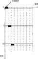
图1是本发明波束扫描方法与传统单波束扫描方法的对比示意图;图1.a所示为传统的单波束扫描系统发射探测脉冲的工作流程;图1.b所示为采用本发明的多波束快速扫描系统的工作流程; Fig. 1 is the comparative schematic diagram of the beam scanning method of the present invention and traditional single-beam scanning method; Fig. 1.a shows the work flow that traditional single-beam scanning system transmits detection pulse; The workflow of beam fast scanning system;
图2是本发明同一次发射中不同脉冲的指向性示意图; Fig. 2 is the directivity schematic diagram of different pulses in the same launch of the present invention;
图3是采用本发明所述的多波束快速扫描方法的一个主动探测装置的结构示意图。Fig. 3 is a schematic structural diagram of an active detection device using the multi-beam fast scanning method of the present invention.
具体实施方式Detailed ways
下面结合附图和具体实施方式对本发明作进一步详细描述: Below in conjunction with accompanying drawing and specific embodiment the present invention is described in further detail:
本发明的原理是在一次发射中发射分别覆盖多个波束的不同脉冲,各脉冲波形采用码分或/和频分方法设计,脉冲之间具有小的互相关性,接收机可根据波形的不同来区分回波所属波束(例如利用同阶的不同本原多项式m序列码对相同载波调相产生的波形),从而获得方位信息。 The principle of the present invention is to transmit different pulses covering multiple beams in one transmission, each pulse waveform is designed by code division or/and frequency division method, there is a small cross-correlation between pulses, and the receiver can use different waveforms To distinguish the beam to which the echo belongs (for example, using different primitive polynomial m-sequence codes of the same order to phase-modulate the waveform of the same carrier), so as to obtain the orientation information. the
作为多波束快速扫描方法的实施例,具体步骤如下: As an embodiment of the multi-beam fast scanning method, the specific steps are as follows:
(1)根据目标系统的具体应用需求确定系统覆盖的探测范围和方位分辨精度,即整个扫描开角φ、以及单个发射波束的宽度Δφ,则所需要扫描的总波束数目为M=φ/Δφ; (1) Determine the detection range and azimuth resolution accuracy covered by the system according to the specific application requirements of the target system, that is, the entire scanning opening angle φ, and the widthΔ φ of a single transmitting beam, then the total number of beams to be scanned is M=φ/Δφ ;
(2)确定每次发射中所能扫描的波束数目。由于在一次发射中覆盖多个波束,等于将发射系统的能量分配到多个波束,在总的发射功率一定的情况下,波束越多,每个波束上的等效源级就越小。所以,需要根据系统设计指标中所要求的每个发射波束上的等效发射源级,来确定一组发射中所能覆盖的波束数目。假设一次发射中所能扫描的波束数目为N,则需要重复K=M/N次扫描以覆盖整个探测范围; (2) Determine the number of beams that can be scanned in each transmission. Since multiple beams are covered in one transmission, it is equivalent to distributing the energy of the transmission system to multiple beams. When the total transmission power is constant, the more beams there are, the smaller the equivalent source level on each beam will be. Therefore, it is necessary to determine the number of beams that can be covered in a group of transmissions according to the equivalent transmission source level on each transmission beam required in the system design index. Assuming that the number of beams that can be scanned in one transmission is N, it is necessary to repeat K=M/N times of scanning to cover the entire detection range;
(3)确定扫描方案,即每次扫描所要覆盖的波束号。尽可能找到一种分配方案,使得在一次发射中所扫描的波束相互位于最小响应位置(避免出现在旁瓣上),以减小不同波束之间的相互干扰; (3) Determine the scanning scheme, that is, the number of beams to be covered by each scanning. Find an allocation scheme as much as possible so that the beams scanned in one transmission are located at the minimum response position (avoid appearing on the side lobe) to reduce the mutual interference between different beams;
(4)采用码分或/和频分方法设计N个互不相关的脉冲波形; (4) adopt code division or/and frequency division method to design N mutually independent pulse waveforms;
(5)根据步骤(3)所确定的方案进行一次扫描发射:将步骤(4)所得到的发射波形对当前所要覆盖的波束分别作预波束形成,并将对应 同一阵元的不同波形的预波束信号相加后发射; (5) Carry out a scanning transmission according to the scheme determined in step (3): use the transmission waveform obtained in step (4) to perform pre-beamforming on the current beams to be covered respectively, and pre-beam the different waveforms corresponding to the same element. The beam signals are summed and then transmitted;
(6)接收脉冲回波,以各发射波形为复本分别对回波进行匹配处理,得到各波束指向上的目标信息; (6) Receive the pulse echo, and use each transmitted waveform as a copy to perform matching processing on the echo, and obtain the target information on each beam point;
(7)重复步骤(5)、步骤(6),在余下的波束中确定下一组波束并进行扫描,重复K次以遍历所有波束。 (7) Steps (5) and (6) are repeated to determine the next group of beams among the remaining beams and perform scanning, repeating K times to traverse all beams. the
图1为本发明所提出的发射波束扫描方法与传统单波束扫描方法的对比示意图。图中T为主动脉冲时间长度,TP为一个脉冲探测周期(两次发射间隔,通常取T+2d/c)。如图1.a所示,传统扫描方法每次发射一个脉冲,对应一个波束。新方法中每次发射多个波形不同的脉冲,分别对应不同的波束,如图1.b所示。为了减小一次发射中不同脉冲之间相互干扰,它们所对应的波束号(方位角)并不连续,而是相互位于其它脉冲所在波束的极小响应位置上,如图2所示。图2是同一次发射中不同脉冲的指向性图,图中脉冲P1、P2、P3分别指向-14°、0°、+14°。在-14°(脉冲P1主瓣峰)处,脉冲P2、P3为极小响应。相应地,P1、P3在0°处为极小响应,P1、P2在+14°处为极小响应。同一次发射中不同脉冲的指向都被选取为满足这种相互位于“零点”的角度,从而进一步减小了不同脉冲间的干扰。仅作为原理描述目的,假设整个探测空间分为M=9个波束,则传统单波束扫描需要9次发射才可以完成覆盖。假设采用新方法后一次发射波所覆盖的波束数为N=3,则只需3次发射,覆盖探测空间所需时间缩短为原来的1/3,信息更新速率提高3倍。 FIG. 1 is a schematic diagram of a comparison between the transmitting beam scanning method proposed by the present invention and the traditional single beam scanning method. In the figure, T is the active pulse time length, and TP is a pulse detection period (the interval between two transmissions, usually T+2d/c). As shown in Figure 1.a, the traditional scanning method emits one pulse at a time, corresponding to one beam. In the new method, multiple pulses with different waveforms are transmitted each time, corresponding to different beams, as shown in Figure 1.b. In order to reduce the mutual interference between different pulses in one transmission, their corresponding beam numbers (azimuth angles) are not continuous, but are located at the minimum response positions of the beams where other pulses are located, as shown in Figure 2. Figure 2 is a directivity diagram of different pulses in the same transmission, in which pulses P1 , P2 , and P3 point to -14°, 0°, and +14°, respectively. At -14° (pulse P1 main lobe peak), pulses P2 , P3 are minimal responses. Correspondingly, P1 and P3 have a minimum response at 0°, and P1 and P2 have a minimum response at +14°. The directions of different pulses in the same transmission are all selected to meet the angle of "zero point" with each other, thereby further reducing the interference between different pulses. For the purpose of principle description only, assuming that the entire detection space is divided into M=9 beams, traditional single-beam scanning requires 9 transmissions to complete coverage. Assuming that the number of beams covered by one transmission wave after the new method is N=3, only three transmissions are required, the time required to cover the detection space is shortened to 1/3 of the original, and the information update rate is increased by 3 times.
图3是采用本发明所述的多波束快速扫描方法的主动探测装置结构示意图。系统采用收/发共用的线阵列,由一个双工转换器完成发射和接收信号的隔离。双工器以下左侧为发射端部分,由波形产生器、预波束形成器、波形相加器及功率放大器组成。右侧为接收端,由波束形成器、相干检测接收机以及回波后处理/显示单元组成。波束选择和扫描控制器控制发射接收端的波束扫描操作。该系统可在一次发射中同时扫描3个波束。工作时,扫描控制器选择一组波束,发射端的预波束形成器据此分别对由主动波形生成器产生3个脉冲波形作相控预波束形成,接下来在波形相加器中,对应同一阵元的波形被相加在一起,并且经过功率放大器送到相应阵元发射。脉冲发射结束后,系统进入回波接收状态,阵列输出信号首先经过前置放大器进行调理放大,然后进入波束形成器,波束形成器根据扫描控制器提供的波束号作波束形成,接下来各波束信号被送入相干检测接收机进行回波检测。相干检测接收机的核心是3个相关器,它们分别以发射脉冲为复本与对应波束的信号做相关。检测接收机输出经过后处理后最终由显示单元显示。一次脉冲周期结束后,扫描控制器选择下一组波束,系统对另外3个波束进行扫描探测。 Fig. 3 is a schematic structural diagram of an active detection device adopting the multi-beam fast scanning method of the present invention. The system adopts a shared line array for receiving and sending, and a duplex converter completes the isolation of transmitting and receiving signals. The left side below the duplexer is the transmitter part, which consists of a waveform generator, a pre-beamformer, a waveform adder and a power amplifier. On the right is the receiver, which consists of a beamformer, a coherent detection receiver, and an echo post-processing/display unit. The beam selection and scanning controller controls the beam scanning operation at the transmitting and receiving ends. The system can simultaneously scan 3 beams in one transmission. When working, the scanning controller selects a group of beams, and the pre-beamformer at the transmitting end performs phase-controlled pre-beamforming on the three pulse waveforms generated by the active waveform generator, and then in the waveform adder, corresponding to the same array The waveforms of the elements are summed together and sent to the corresponding element for transmission through the power amplifier. After the pulse transmission is over, the system enters the echo receiving state. The output signal of the array is conditioned and amplified by the preamplifier first, and then enters the beamformer. The beamformer performs beamforming according to the beam number provided by the scanning controller. Next, each beam signal It is sent to a coherent detection receiver for echo detection. The core of the coherent detection receiver is three correlators, which respectively use the transmitted pulse as a replica to correlate with the signal of the corresponding beam. The detection receiver output is finally displayed by the display unit after post-processing. After a pulse cycle ends, the scanning controller selects the next group of beams, and the system scans and detects the other three beams. the
最后所应说明的是,以上实施例仅用以说明本发明的技术方案而非限制。尽管参照实施例对本发明进行了详细说明,本领域的普通技术人员应当理解,对本发明的技术方案进行修改或者等同替换,都不脱离本发明技术方案的精神和范围,其均应涵盖在本发明的权利要求范围当中。 Finally, it should be noted that the above embodiments are only used to illustrate the technical solutions of the present invention rather than limit them. Although the present invention has been described in detail with reference to the embodiments, those skilled in the art should understand that modifications or equivalent replacements to the technical solutions of the present invention do not depart from the spirit and scope of the technical solutions of the present invention, and all of them should be included in the scope of the present invention. within the scope of the claims. the
Claims (9)
Priority Applications (1)
| Application Number | Priority Date | Filing Date | Title |
|---|---|---|---|
| CN2007101176383ACN101329397B (en) | 2007-06-20 | 2007-06-20 | Method and apparatus for rapidly detecting multi-wave beam |
Applications Claiming Priority (1)
| Application Number | Priority Date | Filing Date | Title |
|---|---|---|---|
| CN2007101176383ACN101329397B (en) | 2007-06-20 | 2007-06-20 | Method and apparatus for rapidly detecting multi-wave beam |
Publications (2)
| Publication Number | Publication Date |
|---|---|
| CN101329397A CN101329397A (en) | 2008-12-24 |
| CN101329397Btrue CN101329397B (en) | 2012-05-30 |
Family
ID=40205298
Family Applications (1)
| Application Number | Title | Priority Date | Filing Date |
|---|---|---|---|
| CN2007101176383AExpired - Fee RelatedCN101329397B (en) | 2007-06-20 | 2007-06-20 | Method and apparatus for rapidly detecting multi-wave beam |
Country Status (1)
| Country | Link |
|---|---|
| CN (1) | CN101329397B (en) |
Families Citing this family (8)
| Publication number | Priority date | Publication date | Assignee | Title |
|---|---|---|---|---|
| DE102010042653A1 (en) | 2010-10-20 | 2012-04-26 | Robert Bosch Gmbh | Method and device for object detection |
| WO2014157496A1 (en)* | 2013-03-29 | 2014-10-02 | 古河電気工業株式会社 | Pulse generation device |
| CN106341170A (en)* | 2015-07-07 | 2017-01-18 | 北京信威通信技术股份有限公司 | Beam training method |
| CN106487437B (en)* | 2015-08-27 | 2020-10-16 | 中兴通讯股份有限公司 | High-frequency synchronization realization method, system and device based on wide and narrow beam access |
| CN106850009B (en)* | 2015-11-30 | 2021-02-09 | 华为技术有限公司 | Method for determining communication beam and corresponding device |
| CN106443659B (en)* | 2016-08-25 | 2018-08-24 | 四川九洲空管科技有限责任公司 | A kind of low-altitude low-velocity small targets detection radar device and its detection method |
| CN109729533B (en)* | 2017-10-30 | 2022-02-01 | 中国移动通信有限公司研究院 | Beam scanning method and related equipment |
| CN109814089B (en)* | 2017-11-22 | 2023-01-03 | 长沙行深智能科技有限公司 | Active detection sensor control method and active detection sensor |
- 2007
- 2007-06-20CNCN2007101176383Apatent/CN101329397B/ennot_activeExpired - Fee Related
Non-Patent Citations (6)
| Title |
|---|
| Rabideau D.J., Parker P..Ubiquitous MIMO Multifunction Digital Array Radar.《2003 Conference Record of the Thirty-Seventh Asilomar Conference on Signals,Systems and Computers》.2003,第1卷1057-1064.* |
| Robey F.C.,Coutts S.,Weikle D.,McHarg J.C.,Cuomo K..MIMO Radar Theory and Experimental Results.《Conference Record of the Thirty-Eighth Asilomar Conference on Signals,Systems and Computers》.2004,第1卷300-304.* |
| 何子述,韩春林,刘波.MIMO雷达概念及其技术特点分析.《电子学报》.2005,第33卷(第12A期),2441-2445.* |
| 保铮 |
| 保铮;张庆文.一种新型的米波雷达──综合脉冲与孔径雷达.《现代雷达》.1995,第17卷(第1期),1-13.* |
| 张庆文.一种新型的米波雷达──综合脉冲与孔径雷达.《现代雷达》.1995,第17卷(第1期),1-13. |
Also Published As
| Publication number | Publication date |
|---|---|
| CN101329397A (en) | 2008-12-24 |
Similar Documents
| Publication | Publication Date | Title |
|---|---|---|
| CN101329397B (en) | Method and apparatus for rapidly detecting multi-wave beam | |
| CN110333293B (en) | A Method for Exciting and Detecting Concrete Defects by Square Grid Phased Ultrasonic Array | |
| CN102955155B (en) | Distributed active phased array radar and beam forming method thereof | |
| US6790182B2 (en) | Ultrasound system and ultrasound diagnostic apparatus for imaging scatterers in a medium | |
| US4458342A (en) | Diversified transmission multichannel detection system | |
| US11921184B2 (en) | Methods and apparatus for characterising the environment of a user platform | |
| US11073611B2 (en) | High spatial resolution 3D radar based on a single sensor | |
| US6736780B2 (en) | Synthetic aperture focusing method for ultrasound imaging based on planar waves | |
| CN110058218B (en) | Radio frequency stealth emission beam forming method and system based on four-dimensional antenna array | |
| JP2011257150A (en) | Azimuth detection device | |
| CN108196250B (en) | Continuous wave radar system and method for low-altitude small target detection | |
| KR101954183B1 (en) | Far-field signal measurement system of active phased array antenna and operation method for thereof | |
| WO1994011757A1 (en) | High resolution phased array echo imager | |
| JP2009002921A (en) | Radar equipment | |
| JP2011180004A (en) | Search radar device, and method of inhibiting unnecessary wave component in the search radar device | |
| CN116500625B (en) | Recovery imaging method, device, system, electronic equipment and readable storage medium | |
| JP2014062779A (en) | Target detection device | |
| CN108627839A (en) | A kind of object detection method and device based on sound wave Gao Gengxin rate emission mode | |
| JP4879761B2 (en) | Radar equipment | |
| CN109188405B (en) | Multi-beam sonar with adjustable beam number and design method | |
| JP2784843B2 (en) | Underwater position measurement method and measurement system | |
| JP2703790B2 (en) | Distance measuring device | |
| TWI702035B (en) | Ultrasonic imaging device and imaging method thereof | |
| JP2623969B2 (en) | Radar equipment | |
| RU2568339C1 (en) | Hydroacoustic system for near illumination |
Legal Events
| Date | Code | Title | Description |
|---|---|---|---|
| C06 | Publication | ||
| PB01 | Publication | ||
| C10 | Entry into substantive examination | ||
| SE01 | Entry into force of request for substantive examination | ||
| C14 | Grant of patent or utility model | ||
| GR01 | Patent grant | ||
| CF01 | Termination of patent right due to non-payment of annual fee | Granted publication date:20120530 Termination date:20150620 | |
| EXPY | Termination of patent right or utility model |