CN101327696A - tape supply box - Google Patents
tape supply boxDownload PDFInfo
- Publication number
- CN101327696A CN101327696ACNA2008101334555ACN200810133455ACN101327696ACN 101327696 ACN101327696 ACN 101327696ACN A2008101334555 ACNA2008101334555 ACN A2008101334555ACN 200810133455 ACN200810133455 ACN 200810133455ACN 101327696 ACN101327696 ACN 101327696A
- Authority
- CN
- China
- Prior art keywords
- tape
- ribbon
- supply
- supply box
- paper
- Prior art date
- Legal status (The legal status is an assumption and is not a legal conclusion. Google has not performed a legal analysis and makes no representation as to the accuracy of the status listed.)
- Granted
Links
Images


Classifications
- B—PERFORMING OPERATIONS; TRANSPORTING
- B41—PRINTING; LINING MACHINES; TYPEWRITERS; STAMPS
- B41J—TYPEWRITERS; SELECTIVE PRINTING MECHANISMS, i.e. MECHANISMS PRINTING OTHERWISE THAN FROM A FORME; CORRECTION OF TYPOGRAPHICAL ERRORS
- B41J15/00—Devices or arrangements of selective printing mechanisms, e.g. ink-jet printers or thermal printers, specially adapted for supporting or handling copy material in continuous form, e.g. webs
- B41J15/04—Supporting, feeding, or guiding devices; Mountings for web rolls or spindles
- B41J15/044—Cassettes or cartridges containing continuous copy material, tape, for setting into printing devices
- B—PERFORMING OPERATIONS; TRANSPORTING
- B41—PRINTING; LINING MACHINES; TYPEWRITERS; STAMPS
- B41J—TYPEWRITERS; SELECTIVE PRINTING MECHANISMS, i.e. MECHANISMS PRINTING OTHERWISE THAN FROM A FORME; CORRECTION OF TYPOGRAPHICAL ERRORS
- B41J15/00—Devices or arrangements of selective printing mechanisms, e.g. ink-jet printers or thermal printers, specially adapted for supporting or handling copy material in continuous form, e.g. webs
- B41J15/04—Supporting, feeding, or guiding devices; Mountings for web rolls or spindles
- B—PERFORMING OPERATIONS; TRANSPORTING
- B41—PRINTING; LINING MACHINES; TYPEWRITERS; STAMPS
- B41J—TYPEWRITERS; SELECTIVE PRINTING MECHANISMS, i.e. MECHANISMS PRINTING OTHERWISE THAN FROM A FORME; CORRECTION OF TYPOGRAPHICAL ERRORS
- B41J17/00—Mechanisms for manipulating page-width impression-transfer material, e.g. carbon paper
- B41J17/02—Feeding mechanisms
- B—PERFORMING OPERATIONS; TRANSPORTING
- B41—PRINTING; LINING MACHINES; TYPEWRITERS; STAMPS
- B41J—TYPEWRITERS; SELECTIVE PRINTING MECHANISMS, i.e. MECHANISMS PRINTING OTHERWISE THAN FROM A FORME; CORRECTION OF TYPOGRAPHICAL ERRORS
- B41J3/00—Typewriters or selective printing or marking mechanisms characterised by the purpose for which they are constructed
- B41J3/407—Typewriters or selective printing or marking mechanisms characterised by the purpose for which they are constructed for marking on special material
- B41J3/4075—Tape printers; Label printers
- B—PERFORMING OPERATIONS; TRANSPORTING
- B41—PRINTING; LINING MACHINES; TYPEWRITERS; STAMPS
- B41J—TYPEWRITERS; SELECTIVE PRINTING MECHANISMS, i.e. MECHANISMS PRINTING OTHERWISE THAN FROM A FORME; CORRECTION OF TYPOGRAPHICAL ERRORS
- B41J31/00—Ink ribbons; Renovating or testing ink ribbons
- B41J31/12—Ink ribbons having arrangements to prevent undesired contact between the impression-transfer material and machine parts or other articles
- B—PERFORMING OPERATIONS; TRANSPORTING
- B41—PRINTING; LINING MACHINES; TYPEWRITERS; STAMPS
- B41J—TYPEWRITERS; SELECTIVE PRINTING MECHANISMS, i.e. MECHANISMS PRINTING OTHERWISE THAN FROM A FORME; CORRECTION OF TYPOGRAPHICAL ERRORS
- B41J35/00—Other apparatus or arrangements associated with, or incorporated in, ink-ribbon mechanisms
- B41J35/04—Ink-ribbon guides
Landscapes
- Impression-Transfer Materials And Handling Thereof (AREA)
- Handling Of Continuous Sheets Of Paper (AREA)
- Printers Characterized By Their Purpose (AREA)
- Packaging Of Annular Or Rod-Shaped Articles, Wearing Apparel, Cassettes, Or The Like (AREA)
- Unwinding Webs (AREA)
- Wrappers (AREA)
- Automatic Tape Cassette Changers (AREA)
- Handling Of Sheets (AREA)
Abstract
Translated fromChinese
Description
Translated fromChinese本申请为申请人于2000年8月2日提交的申请号为00813373.5(PCT/US00/40541),发明名称为“纸带供给盒”的分案申请,。This application is a divisional application with the application number 00813373.5 (PCT/US00/40541) submitted by the applicant on August 2, 2000, and the title of the invention is "Paper Tape Supply Box".
技术领域technical field
本发明整体涉及一种纸带供给盒,具体而言,是涉及一种用于标签机中的纸带供给盒,该标签机用于将标记打印在这种纸带上,以便用来有选择地粘贴到所需物质上。进一步具体地说,本发明涉及通常被用作不分层的、热转印纸带供给盒类型的纸带供给盒。This invention relates generally to a tape supply cassette, and more particularly to a tape supply cassette for use in a labeling machine for printing indicia on such tape for use in selective Paste it on the desired substance. More particularly, the present invention relates to tape supply cassettes of the type commonly used as non-laminated, thermal transfer tape supply cassettes.
背景技术Background technique
现已存在大量用于连接标签或条带打印机等的现有技术的纸带供给盒和相关专利。这些纸带供给盒向打印头提供卷绕的打印纸带,用于在随后将被有选择地粘贴到所需物质上的纸带上打印标记。美国专利Nos.5,188,469;5,350,243;5,653,542;5,813,773;4,927,278;4,983,058和5,419,648等例举和公开了这些纸带供给盒中的一些纸带供给盒。这些纸带供给盒被设计用于标签机或打印机中,这些标签机或打印机具有用于将该盒容纳在一个可操作位置的盒容纳腔、一个热打印头和一个相关联的压纸辊,该关联压辊被有选择地朝向或背离打印头移动,并将纸带放置在关联压辊和打印头之间,其目的是为了在该纸带上定影图像或转印图像。这样的标签机或打印机也包括用于推进纸带穿过打印头以及推进各种其它的卷轴元件通过设备的装置。There are a large number of prior art tape supply cassettes and related patents for connection to label or strip printers and the like. These tape supply cassettes provide the printhead with wound printing tape for printing indicia on the tape which will then be selectively affixed to the desired substance. Some of these tape supply cassettes are illustrated and disclosed in US Patent Nos. 5,188,469; 5,350,243; 5,653,542; 5,813,773; 4,927,278; These tape supply cassettes are designed for use in labeling machines or printers having a cassette receiving chamber for housing the cassette in an operative position, a thermal print head and an associated platen roller, The associated platen roller is selectively moved toward or away from the printhead, and the paper web is placed between the associated platen roller and the printhead for the purpose of fixing or transferring an image on the paper web. Such labelers or printers also include means for advancing the paper web through the printhead and advancing various other spool elements through the apparatus.
虽然现有技术的纸带供给盒对于它们的特殊应用而言,能够令人满意地工作,但是仍不断需要对这样的纸带供给盒进行改进。此处不断需求改进的主要特征包括:纸带供给盒相对转印色带容纳不同尺寸和宽度的纸带的能力,纸带供给盒引导纸带穿过该供给盒并同时保证达到合适的纸带阻力的能力和纸带供给盒在切割位置最小化纸带的堵塞的能力等。因此,需要一种改进的用于上述纸带打印机的纸带供给盒和用于这种纸带供给盒的纸带。While prior art tape supply cassettes work satisfactorily for their particular application, there is a continuing need for improvements to such tape supply cassettes. Key features that are in constant need of improvement here include the ability of the tape supply cassette to accommodate tapes of different sizes and widths relative to the transfer ribbon, the tape supply cassette guiding the tape through the cassette while ensuring that the proper tape is achieved The ability of the resistance and the ability of the tape supply box to minimize the jamming of the tape at the cutting position, etc. Accordingly, there is a need for an improved tape supply cassette for the above-described tape printer and tape for such a tape supply cassette.
发明内容Contents of the invention
因此,本发明的一个目的是提供一种用于标签机或打印机的改进的纸带供给盒。SUMMARY OF THE INVENTION It is therefore an object of the present invention to provide an improved tape supply cassette for a labeling machine or printer.
本发明的另一个目的是提供一种用于这种供给盒的改进的纸带引导装置。Another object of the present invention is to provide an improved tape guide for such a cassette.
本发明的另一个目的是提供一种结合纸带参数的改进的纸带供给和引导机构,以保证纸带穿过供给盒的最优化运动,同时防止纸带供给卷轴空转。Another object of the present invention is to provide an improved tape feed and guide mechanism that incorporates tape parameters to ensure optimum movement of the tape through the supply cassette while preventing the tape supply spool from idling.
本发明的另一个目的是在供给盒的纸带出口端提供一种改进的装置,以便限制或消除由于打印纸带和纸带切割装置之间的相互作用而导致的阻塞问题。Another object of the present invention is to provide an improved arrangement at the tape outlet end of the supply cassette to limit or eliminate jamming problems due to interaction between the printing tape and the tape cutting means.
本发明的另一个目的是提供一种改进的不分层的、热转印类型的纸带供给盒。Another object of the present invention is to provide an improved non-laminated, thermal transfer type tape supply cassette.
根据本发明,提供了一种用于这样一种类型打印机的纸带供给盒,该打印机具有:供给盒容纳腔、限定打印站的打印头、和在打印和非打印位置之间可相对地朝向和离开打印头移动的压纸辊,所述供给盒包括:盒顶,盒底,和纸带的卷轴,所述盒底包括:旋转式支撑卷轴的纸带供给毂,和从毂径向向外延伸的多个纸带支撑筋,所述盒顶包括:与所述毂对齐的基本上环形的筋,筋具有适应于毂外圆尺寸的内圆尺寸,毂的上部边缘座落在筋中,和从筋径向向外延伸的多个纸带支撑筋,其中,筋与筋一起沿竖直方向支撑所述卷轴,定位盘设置在供给盒顶和纸带卷供给卷轴之间和供给盒底和纸带供给卷轴之间;和筋通过定位盘在竖直方向上支撑纸带供给卷轴。According to the present invention, there is provided a tape supply cassette for a printer of the type having a supply cassette receiving chamber, a printhead defining a printing station, and relatively oriented between printing and non-printing positions. and a platen roller that moves away from the printhead, the supply cassette includes a top, a bottom, and a spool of tape, the bottom of which includes a tape supply hub that rotatably supports the spool, and radially from the hub a plurality of paper tape support ribs extending outwardly, said box top comprising: a substantially annular rib aligned with said hub, the rib having an inner circular dimension adapted to the outer circumferential dimension of the hub, the upper edge of the hub seated in the rib , and a plurality of paper tape supporting ribs extending radially outward from the ribs, wherein the ribs together with the ribs support the reel in the vertical direction, and the positioning plate is arranged between the supply box top and the paper tape roll supply reel and the supply box Between the bottom and the tape supply reel; and the rib supports the paper tape supply reel in the vertical direction through the positioning plate.
通过参考附图、对优选实施例以及附属的权利要求书的说明,本发明的这些和其它目的将变得更加清楚。These and other objects of the present invention will become clearer by referring to the accompanying drawings, the description of the preferred embodiments and the appended claims.
附图说明Description of drawings
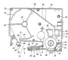
图1是根据本发明的纸带供给盒的等角视图。Figure 1 is an isometric view of a tape supply cassette in accordance with the present invention.
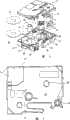
图2是本发明的纸带供给盒的等角、分解视图。Figure 2 is an isometric, exploded view of the tape supply cassette of the present invention.
图3是本发明的纸带供给盒底的内侧立面图,其中该纸带供给盒具有纸带供给卷轴、色带供给卷轴和色带重绕卷轴,而各种其它的元件被移去。Figure 3 is an inside elevational view of the base of the tape supply cassette of the present invention with the tape supply spool, the ribbon supply spool and the ribbon rewind spool with various other components removed.
图4是纸带供给盒顶的内侧立面图。Figure 4 is an inside elevational view of the top of the tape supply cassette.
图5是组装好的纸带供给盒的底立图。Figure 5 is a bottom elevation view of the assembled tape supply cassette.
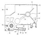
图6是与图3相似的纸带供给盒底的内侧立图,表示了纸带和色带的路径。Figure 6 is an inside elevation view of the bottom of the tape supply cassette similar to Figure 3, showing the path of the tape and ribbon.
图7是一个局部视图,部分地表示了与纸带切割装置相结合的纸带供给盒的纸带出口端。Figure 7 is a fragmentary view partially showing the tape outlet end of the tape supply cassette in combination with the tape cutting means.
图8是纸带供给盒的纸带出口端的局部前立图。Figure 8 is a partial front elevational view of the tape outlet end of the tape supply cassette.
图9表示了与图6相似的纸带供给盒的视图,其中该纸带供给盒结合了纸带切割装置的第二实施例。Figure 9 shows a view of a tape supply cassette similar to that of Figure 6 incorporating a second embodiment of the tape cutting device.
图10是一个部分剖视图,表示了沿图3中的剖面线9-9的视图。FIG. 10 is a partial sectional view showing the view along section line 9-9 in FIG. 3. FIG.
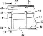
图11a是一个部分剖视图,表示了沿图10中的剖面线11-11的视图。Figure 11a is a partial sectional view showing the view along section line 11-11 in Figure 10.
图11b是一个与图11a相似的视图,只是将纸带供给盒的顶和底组装在一起。Figure 11b is a view similar to Figure 11a but with the top and bottom of the tape supply cassette assembled.
图12是一个部分剖视图,表示了与图10相似的另一个实施例。Fig. 12 is a partial sectional view showing another embodiment similar to Fig. 10 .
图13a是一个部分剖视图,表示了沿图12中的剖面线13-13的视图。FIG. 13a is a partial sectional view showing the view along section line 13-13 in FIG. 12. FIG.
图13b是一个与图13a相似的视图,只是将纸带供给盒的顶和底组装在一起。Figure 13b is a view similar to Figure 13a, but with the top and bottom of the tape supply cassette assembled.
图14是纸带供给盒的一部分的局部剖视图,表示了安装在两半纸带供给盒之间的纸带供应品。Figure 14 is a partial cross-sectional view of a portion of the tape supply cassette showing the tape supply mounted between the tape supply cassette halves.
图15是一个部分剖视图,表示了沿图3中剖面线15-15的视图。FIG. 15 is a partial sectional view showing the view taken along section line 15-15 of FIG. 3. FIG.
图16是一个剖视图,表示了纸带的结构。Fig. 16 is a sectional view showing the structure of the tape.
具体实施方式Detailed ways
本发明涉及一种纸带供给盒,具体而言,是涉及一种通常被用作不分层的纸带供给盒。这种类型的纸带供给盒被设计用于标签机或打印机中,这些标签机或打印机包括一个纸带供给盒容纳腔、一个打印头7(图6)、一个可朝向或背离打印头7移动以限定打印和非打印位置的压纸辊8、用于推进纸带和色带穿过纸带供给盒并经过打印站的装置和在打印后有选择地切断纸带的装置。This invention relates to a tape supply cassette and, more particularly, to a tape supply cassette which is generally used as a non-layered tape supply cassette. This type of tape supply cassette is designed for use in labeling machines or printers that include a tape supply cassette chamber, a print head 7 (Fig. 6), a
在对本发明优选实施例的说明中,首先参见图1和图2,其中图1表示了完全组装形式的供给盒,图2表示了分解形式的供给盒。一般地说,供给盒10包括供给盒顶11和供给盒底12。组装时,将顶11和底12固定在一起构成供给盒10,该供给盒10容纳纸带供应品13、色带供给卷轴23和色带卷带轴17。该供给盒还包括纸带出口端14、设置在该纸带出口端14上的纸带出口槽15以及当该供给盒被插入到打印机中时用于容纳打印头的打印头空腔或凹槽区域16。该打印头空腔被纸带/色带引导臂38在一侧限定,其中该引导臂38用于将纸带和色带引导到打印站。供给盒顶11与底12中的区域18和19分别限定容纳色带供给卷轴23和色带卷带轴17的区域。纸带推进辊20被设置在供给盒的纸带出口端。在优选实施例中,辊20是一个具有内花键、筋或其它与打印机驱动轴相配合的装置的驱动送纸辊。In describing the preferred embodiment of the invention, reference is first made to Figures 1 and 2, wherein Figure 1 shows the supply box in fully assembled form and Figure 2 shows the supply box in exploded form. Generally speaking, the
插销筋21被设置在供给盒的一侧,与打印机上的一个插销件(未示出)相配合,从而在供给盒被插入供给盒空腔时将供给盒固定在打印机中。第二插销筋22(图3)被设置在供给盒底12上的相反一侧,与第二打印机插销件(未示出)相配合。A
参见图2和图3,供给盒底12的内部被十分清楚地进行了表示。如图所示,供给盒底12包括底壁25和侧壁24,该侧壁24从底壁25基本上按直角向上延伸并围绕供给盒的基本部分延伸。与底壁25加工成一整体的是纸带供给毂26和数个纸带支撑筋28,这些纸带支撑筋28从毂26径向向外延伸。毂26通常呈圆柱形结构,从底壁25基本上按直角向上延伸,且其作用为可旋转地支撑纸带供给卷轴13的毂84。一对纸带遏制壁部分29、29被设置用于将纸带供给卷轴13包含在一个基本呈环形的结构中。伸长的纸带引导壁30从侧壁24的内侧部分延伸到位于一对隔开的壁部分32、32之间的纸带通过槽31处。该引导壁30从底壁25基本上按直角向上延伸,并确保将来自纸带供应品13的纸带恰当并准确地从纸带卷轴13引导至纸带通过槽31。Referring to Figures 2 and 3, the interior of the
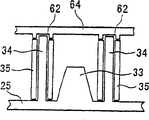
一对纸带导向件/柱34、34与底壁25加工成一整体,并且该纸带导向件/柱34、34从底壁25基本上按直角向上延伸。该纸带导向件/柱34、34支撑相应的用于引导缠绕在色带供给卷轴23上的带的辊35、35,其中该色带供给卷轴23被可旋转地安装在支撑柱36上。在优选实施例中,辊35、35具有通常呈圆柱形的结构,并且具有一个稍大于柱34、34外径的圆柱形内部开口。这使得纸带被纸带推进装置自由推动且围绕柱34、34被推进。在优选实施例中,一个阻挡件33被放置在辊35、35之间,用于防止纸带在辊35、35之间无意或有意地发送。因此,该件33迫使纸带围绕在辊35、35的外侧只有单一路径。从图15可清楚地看出,该阻挡件最好具有截面基本上呈梯形的结构。A pair of tape guides/posts 34 , 34 are integrally formed with
由供给盒底12的一部分限定的纸带/色带引导臂38包括一个外侧壁39和一个内侧壁40,它们大体上彼此平行。壁39和40中的每一个壁从底壁25起均具有大体相同的高度,且高于延伸围绕在供给盒底外周的侧壁24的主要部分。大体位于壁39和40之间的中间部分处的是一个纸带/色带隔离壁或阻挡件,该纸带/色带隔离壁或阻挡件由一对柱41、41和一个壁部分42限定,其中该壁部分42与该柱41、41加工成一整体在一起并在柱41、41之间延伸。最好如图10所示,柱41、41高于壁部分39和40,并且壁部分42或者明显矮于柱41、41,或者明显矮于壁39和40。柱41、41的上端设置有凹槽部分44,该凹槽部分44被设计成用于容纳上纸带引导件45,该上纸带引导件45与供给盒顶11限定纸带/色带引导臂38的相应部分加工成一整体。供给盒顶11的这一部分包括一对矮壁部分46和47,这些矮壁部分46和47被设计用于当供给盒被组装时与壁部分39和40相配合。The tape/
底壁25在纸带/色带引导臂38的区域内设置有一对底纸带/色带引导边48和49,分别用于引导纸带和色带的下边缘以相同高度通过引导臂38。相反,位于壁部分42和壁40之间的阻挡件色带侧则设置有一对引导边,这对引导边只用于引导色带的带边。阻挡件的位于壁部分42和壁39之间的纸带侧设置有一对隔开的纸带引导件45,这对引导件只用于引导纸带的带边。The
如图11b所示,当供给盒顶11和底12被组装时,纸带/色带引导臂38限定一个用于色带的引导通道50和一个用于纸带的引导通道51。如图所示,图10、11a和11b表示的特定实施例被设计用于一种供给盒,在该盒中色带比纸带宽,并且在该盒中纸带和色带的底边均被处于同一高度的共用引导边引导。在图11a和11b的实施例中,纸带引导边49同时引导纸带和色带的底边,而引导边52则引导色带的顶边,引导件45则引导纸带的顶边。As shown in Figure 11b, when the
图12、13a和13b表示了用于纸带臂的一个替代实施例。图12、13a和13b的实施例与图10、11a和11b的实施例相似,除了该实施例被设计用于一种供给盒,在该盒中纸带和色带具有相同的宽度以外。如图13b所示被组装时,该实施例中纸带/色带引导臂限定一个色带通道50和一个纸带通道51,这两个通道具有相同的高度尺寸。如图所示,当纸带/色带引导臂38被组装时,臂38限定色带通道50和具有相同高度的纸带通道51。在该实施例中,通道50和51二者在其底部均被引导边49限定,并且在其顶部均被引导边52限定。Figures 12, 13a and 13b show an alternative embodiment for the tape arm. The embodiment of Figures 12, 13a and 13b is similar to that of Figures 10, 11a and 11b, except that it is designed for use with a supply cassette in which the paper and ribbon are of the same width. When assembled as shown in Figure 13b, the ribbon/ribbon guide arm in this embodiment defines a
供给盒底还包括数个连接孔55,这些连接孔55位于穿过供给盒底的位置上,用于与来自供给盒顶的相应的连接柱56相配合,从而当供给盒被组装时,保持供给盒顶11和底12被连接在一起。The bottom of the supply box also includes several connection holes 55 which are positioned through the bottom of the supply box for cooperating with corresponding connection posts 56 from the top of the supply box so that when the supply box is assembled, the The
在纸带和色带离开引导臂38以后,它们经过打印站,如图6所示。从那,色带被引导围绕限定打印头凹槽16的壁,同时纸带被引导通过纸带推进器或送纸辊20。在优选实施例中,引导筋58和59不但处于同一高度,而且与引导臂38中的引导边48和49也处于同一高度。After the paper and ribbon exit the
最好如图1-6所示,打印头凹槽区域16在一侧被供给盒底的内壁部分40和供给盒顶的内壁部分68限定,在相反的一侧被壁部分86、88和89限定。这些壁部分86、88和89与底壁25加工成一整体,并且从底壁25基本上按直角向上延伸。这些壁部分86、88和89在其侧边彼此相互连接,构成一个大体连续的壁,该壁与壁部分40一起限定空腔16。如图所示,壁部分86和40的端部彼此隔开,从而提供一个开口,压纸辊8(图6)可以穿过该开口相对打印头7移动,以限定打印站。这些壁部分86、88和89共同构成一个引导部分,用于在打印站引导紧随打印操作的色带。如图所示,壁部分86和88之间以及壁部分88和89之间的连接设置有圆形边90和91,从而为向色带卷带轴17推进色带提供光滑的低摩擦表面。As best shown in FIGS. 1-6, the
如图4所示的供给盒顶11包括顶壁64和侧壁65,该侧壁65延伸围绕供给盒顶11外周的侧壁24的大部分。供给盒顶的一部分对应于纸带/色带引导臂38。该部分包括一个外边66和一个内边68,它们大体上彼此平行,并且分别对应于供给盒底12的边39和40。在优选实施例中,壁部分66和68比侧壁65的剩余部分矮。The
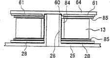
供给盒顶11的内侧包括相应于供给盒底12中的各种元件的元件,这些元件包括数个位于穿过顶壁64的位置上的连接柱56。这些连接柱56被设计用于插入供给盒底中的相应连接孔55中,从而将顶11固定到底12上。该供给盒顶还包括一个通常呈环形的筋60和数个从该筋60径向向外延伸的筋61。该环形筋60与毂26(图3)对齐,并且具有与毂26的外环尺寸大体相等的内环尺寸,从而当供给盒被组装时,毂26的上边便座落在环形筋60中。筋61与供给盒底的筋28相似,其作用为沿对供给盒顶和底垂直的方向支撑纸带11的卷轴。该供给盒顶11还包括一对柱容纳孔62、62,其具有内环尺寸,被设计用于容纳引导柱34、34的上端,如图15所示。The inside of the
最好如图5所示,供给盒的底侧包括一个与内毂26相对齐的开口69和位于供给盒底的一个角中的凹槽区域70,该区域70用于容纳数个供给盒检查孔71。这些孔71与一个或多个与打印机相关联的柱塞开关对齐,目的是向打印机提供关于供给盒内的纸带的特征,例如,纸带宽度、它是分层的还是不分层的,等等。该供给盒底还包括一个开口72,色带卷带轴穿过该开口72从打印机处延伸到与色带卷带轴17相互作用,并转动色带卷带轴17。纸带推进开口74被设置在供给盒的纸带出口端附近,并且被设计用于在打印机的纸带推进轴和纸带推进卷轴20之间提供一个接口。As best shown in Figure 5, the bottom side of the supply box includes an
如图7和8所示,纸带出口端14包括一个通常呈平面的表面75、肩部76和纸带出口槽或开口15。该平面表面75最好从肩部76开始经过槽15延伸至供给盒的最上端。在优选实施例中,大体呈平面的表面75与肩部76共同构成一个凹槽区域,用于容纳打印机的固定纸带切割件78的一个实施例。如图所示,该件78从供给盒侧壁的一个外表面部分和插销筋向内延伸。与切割件78相关联的是一个第二切割件79,该第二切割件79被设计成朝向和背离切割件78运动,如图所示。在图7的实施例中,切割装置是一种剪切机构,在该机构中切割件78容纳剪刀的一半,而切割件79则包含剪刀的另一半。为了有助于防止在切割操作中纸带挂在或卡在切割件79上,纸带出口槽15沿纸带穿过壁部分80的方向向上具有一定的角度。该槽15倾斜的角度值最好大于约5°,在大约5°和60°之间更好。As shown in FIGS. 7 and 8 , the
虽然对倾斜出口槽15的要求少于对例如图7中所示的剪刀切割机构的要求,但是当与例如图9中所示的切割机构,即钝切割机构一起使用时,这种倾斜出口槽就特别理想。具体而言,这种机构包括固定支撑件81和刀件82。在这种类型的切割机构中,刀件82沿相对一个枢转点的圆弧与支撑件81进行可移动切割配合。当该带角度的槽15被用于这种类型的切割机构时,能够使刀部分82从支撑件81移开,而不会带着纸带随其一块运动。若没有这种倾斜的或带角度的出口开口15,切割刀82卡住纸带端部从而阻塞打印机的趋势则明显增加。While the requirements for an
最好如图2和14所示,纸带卷轴13包括一个中心支撑毂84,该中心支撑毂84被设计用于套在毂26上。当纸带13的卷轴被组装到供给盒中后,在该纸带卷轴13的每一侧都放置有一个定位盘85。该定位盘包括一个表面(内表面)和一个与之相反的表面(外表面),其中该内表面是胶粘的或者包括少量的粘结剂,而外表面是相对光滑的或者是无摩擦的。定位盘85、85起两种主要作用。第一,它们防止当供给盒不被使用或正在操作时纸带13的卷轴空转或者松开。若没有盘85、85,供给盒的任何运动都可能引起纸带13的卷轴松开。第二,定位盘85、85控制纸带卷轴13的拖曳量。结合纸带的具体类型和硬度以及需要推进或拉动纸带围绕辊35、35的力的量,该拖曳必须是这样的,即确保纸带被合适地推进并穿过供给盒。具体而言,当纸带经过供给盒并且通过打印头时,纸带应该具有足够的拖曳量,从而该纸带将不会空转或松弛。另一方面,该拖曳量必须足够小,从而使纸带推进装置正向推进纸带穿过系统。另外,这种控制拖曳不论是在卷轴13的始端还是在卷轴13的末端都必须是连续的。此外,纸带还必须足够硬,以防止纸带卡在纸带切割机构上,从而阻塞打印机。As best shown in FIGS. 2 and 14 , the
用于本发明的供给盒的纸带13倾向于是一种所谓的不分层纸带,该纸带包括打印接收纸带层和释放层。具体而言,最好如图16所示,该打印接收纸带层包括基片92和涂敷在其上的涂层93。在优选实施例中,基片92是聚乙烯-对苯二酸盐(PET)片。该基片92最好具有惰性填料,例如,二氧化钛(TiO2),以使该基片呈白色。因为TiO2的存在,所以优选基片92的比重大于约1.1,大于约1.2更好,大于约1.3最好。具有这种惰性填料,例如,二氧化钛(TiO2),最好是用于现有技术基片中的化学增白剂,因为这种惰性填料在加热时能够提供尺寸稳定性并且防止变色。该基片92最好约2密耳(0.002英寸)厚。用于制造本发明的纸带13的这种类型的基片最好是由杜邦(Dupont)公司生产的PET基片。The
在基片92的打印接收表面上涂敷有一层热活化聚酯树脂涂层93。该聚酯树脂涂层93是一种相对薄的涂层,其作用主要是接收来自转印纸带的打印图像。因此,涂层92的化学特性必须是和转印色带的化学特性相容的。另外,涂层93和基片92二者最好是相容的(即二者都为聚酯)。On the print receiving surface of
一层粘结剂层94被涂敷到基片92的反面。这种粘结剂最好是优质的、自交叉链接丙烯酸粘结剂,该粘结剂对UV辐射以及各种化学物质和石油馏出物具有抵抗性。An
纸带13的第二部分是释放衬垫,该衬垫包含纸板95、中间涂层96和外释放涂层97。在优选实施例中,该纸层95是密度增大的牛皮纸,涂层96是一层聚乙烯涂层,而涂层97是一层硅涂层。The second part of the
在优选实施例中,纸带13的整体厚度约7密耳(0.007英寸),包括比释放衬垫部分(包含纸层95以及涂层96和97)薄的打印接收纸带部分(包含基片92以及层93和94)。In a preferred embodiment, the
设置在色带供给卷轴23上的色带是所谓的一种热转印或热活性色带。换言之,该色带能够有效地将图像从色带转印到纸带的打印接收表面上。用于本发明的供给盒的纸带和色带最好彼此相容。The ribbon provided on the
对于本发明的供给盒而言,纸带具有足够的硬度也是重要的,从而当纸带从出口槽15出去并且被切割机构切割时,该纸带能足够硬以阻止随可移动切割件的缩回而运动。在优选实施例中,通过纸板层95与涂层96和97的总共厚度大于纸带打印接收部分的厚度而得到这样的硬度。For the supply box of the present invention, it is also important that the paper strip has sufficient stiffness so that when the paper strip exits the
当供给盒被完全组装好时,纸带从纸带卷轴13沿图6所示的纸带路径延伸。具体而言,纸带从卷轴13处开始延伸穿过元件32、32之间的路径31,并且在卷轴13处纸带受到引导壁30的引导。纸带从那围绕引导辊35、35继续延伸,并且经过引导臂38中位于柱41、41和壁部分39之间的路径51。从那儿纸带接着延伸到并穿过位于打印头7和压纸辊8之间的打印区域,然后经过位于辊20和打印机驱动辊9之间的推进区域,之后向外穿出出口槽15。色带从色带供给卷轴23处开始延伸,经过位于柱41、41和壁部分40之间的路径50,穿过位于打印头7和压纸辊8之间的打印区域,然后围绕壁部分86、88和89到达色带卷带轴17。When the supply cassette is fully assembled, the tape extends from the
虽然对于优选实施例的说明已非常具体,但在不偏离本发明思想的条件下,可以做各种修改。因此,本发明的范围旨在由附属的权利要求书提出,而非由优选实施例的说明限定。Although the description of the preferred embodiment has been very specific, various modifications can be made without departing from the concept of the present invention. Accordingly, the scope of the invention is intended to be set forth by the appended claims rather than to be limited by the description of the preferred embodiments.
Claims (1)
Translated fromChineseApplications Claiming Priority (3)
| Application Number | Priority Date | Filing Date | Title |
|---|---|---|---|
| US14758299P | 1999-08-06 | 1999-08-06 | |
| US60/147582 | 1999-08-06 | ||
| US60/147,582 | 1999-08-06 |
Related Parent Applications (1)
| Application Number | Title | Priority Date | Filing Date |
|---|---|---|---|
| CNB008133735ADivisionCN1251877C (en) | 1999-08-06 | 2000-08-02 | tape supply box |
Publications (2)
| Publication Number | Publication Date |
|---|---|
| CN101327696Atrue CN101327696A (en) | 2008-12-24 |
| CN101327696B CN101327696B (en) | 2013-05-22 |
Family
ID=22522143
Family Applications (7)
| Application Number | Title | Priority Date | Filing Date |
|---|---|---|---|
| CN2008101334555AExpired - LifetimeCN101327696B (en) | 1999-08-06 | 2000-08-02 | tape supply box |
| CN2005100714341AExpired - LifetimeCN1680111B (en) | 1999-08-06 | 2000-08-02 | Print tape supply cassette |
| CN2006101003695AExpired - LifetimeCN1899837B (en) | 1999-08-06 | 2000-08-02 | tape supply box |
| CN201110107197.5AExpired - LifetimeCN102241204B (en) | 1999-08-06 | 2000-08-02 | Tape supply cartridge |
| CNB008133735AExpired - LifetimeCN1251877C (en) | 1999-08-06 | 2000-08-02 | tape supply box |
| CN2006101018510AExpired - LifetimeCN1880095B (en) | 1999-08-06 | 2000-08-02 | Tape supply cartridge |
| CN200510055849XAExpired - LifetimeCN1663807B (en) | 1999-08-06 | 2000-08-02 | tape supply box |
Family Applications After (6)
| Application Number | Title | Priority Date | Filing Date |
|---|---|---|---|
| CN2005100714341AExpired - LifetimeCN1680111B (en) | 1999-08-06 | 2000-08-02 | Print tape supply cassette |
| CN2006101003695AExpired - LifetimeCN1899837B (en) | 1999-08-06 | 2000-08-02 | tape supply box |
| CN201110107197.5AExpired - LifetimeCN102241204B (en) | 1999-08-06 | 2000-08-02 | Tape supply cartridge |
| CNB008133735AExpired - LifetimeCN1251877C (en) | 1999-08-06 | 2000-08-02 | tape supply box |
| CN2006101018510AExpired - LifetimeCN1880095B (en) | 1999-08-06 | 2000-08-02 | Tape supply cartridge |
| CN200510055849XAExpired - LifetimeCN1663807B (en) | 1999-08-06 | 2000-08-02 | tape supply box |
Country Status (9)
| Country | Link |
|---|---|
| US (1) | US6520696B2 (en) |
| EP (3) | EP1242246B1 (en) |
| JP (3) | JP4543601B2 (en) |
| KR (1) | KR100749361B1 (en) |
| CN (7) | CN101327696B (en) |
| AT (3) | ATE432169T1 (en) |
| AU (1) | AU2806701A (en) |
| DE (2) | DE60020164T2 (en) |
| WO (1) | WO2001010649A1 (en) |
Cited By (10)
| Publication number | Priority date | Publication date | Assignee | Title |
|---|---|---|---|---|
| CN101850675A (en)* | 2009-03-31 | 2010-10-06 | 兄弟工业株式会社 | Tape box |
| US9381756B2 (en) | 2009-03-31 | 2016-07-05 | Brother Kogyo Kabushiki Kaisha | Tape cassette |
| US9498988B2 (en) | 2009-03-31 | 2016-11-22 | Brother Kogyo Kabushiki Kaisha | Tape cassette |
| US9498998B2 (en) | 2008-12-25 | 2016-11-22 | Brother Kogyo Kabushiki Kaisha | Tape cassette |
| US9533522B2 (en) | 2008-12-25 | 2017-01-03 | Brother Kogyo Kabushiki Kaisha | Tape cassette |
| US9539837B2 (en) | 2009-12-16 | 2017-01-10 | Brother Kogyo Kabushiki Kaisha | Tape cassette |
| US9616690B2 (en) | 2009-03-31 | 2017-04-11 | Brother Kogyo Kabushiki Kaisha | Tape cassette |
| US9656495B2 (en) | 2009-12-28 | 2017-05-23 | Brother Kogyo Kabushiki Kaisha | Tape cassette |
| US9676217B2 (en) | 2009-06-30 | 2017-06-13 | Brother Kogyo Kabushiki Kaisha | Tape cassette |
| US12296580B2 (en) | 2009-03-31 | 2025-05-13 | Brother Kogyo Kabushiki Kaisha | Tape cassette |
Families Citing this family (55)
| Publication number | Priority date | Publication date | Assignee | Title |
|---|---|---|---|---|
| USD542334S1 (en)* | 2002-05-15 | 2007-05-08 | Brother Industries, Ltd. | Tape cartridge for tape printing machine |
| USD534203S1 (en)* | 2002-05-15 | 2006-12-26 | Brother Industries, Ltd. | Tape cartridge for tape printing machine |
| US6910819B2 (en) | 2003-08-12 | 2005-06-28 | Brady Worldwide, Inc. | Printer cartridge |
| GB2412351A (en)* | 2004-03-24 | 2005-09-28 | Esselte | A tape printer having separate tape and ink ribbon cassettes |
| CN101060985B (en)* | 2004-09-24 | 2012-06-13 | 兄弟工业株式会社 | Tape cassette and tape printer |
| GB0423010D0 (en)* | 2004-10-15 | 2004-11-17 | Esselte | Cassette |
| USD527419S1 (en)* | 2004-11-18 | 2006-08-29 | King Jim Co., Ltd. | Tape cartridge for a tape writing device |
| JP4561442B2 (en)* | 2005-03-30 | 2010-10-13 | ブラザー工業株式会社 | Tape cassette |
| GB0521754D0 (en)* | 2005-10-25 | 2005-11-30 | Esselte | Tape printing apparatus |
| US7441970B2 (en)* | 2005-11-10 | 2008-10-28 | Datacard Corporation | Ribbon tensioning mechanisms |
| JP4904882B2 (en) | 2006-03-29 | 2012-03-28 | ブラザー工業株式会社 | Printing cassette and lettering tape |
| JP2007301872A (en)* | 2006-05-12 | 2007-11-22 | Seiko Epson Corp | Split case, case disassembly device and tape cartridge |
| CN101334600B (en)* | 2007-06-26 | 2010-06-02 | 京瓷美达株式会社 | Sheet-feeding device and image forming apparatus provided with the same |
| GB2459531B (en)* | 2008-04-29 | 2010-10-13 | Dymo Nv | Label printer |
| PL2414165T3 (en)* | 2009-03-31 | 2014-08-29 | Brother Ind Ltd | Tape cassette and tape printer |
| JP4947085B2 (en)* | 2009-03-31 | 2012-06-06 | ブラザー工業株式会社 | Tape cassette |
| JP5062239B2 (en)* | 2009-11-27 | 2012-10-31 | ブラザー工業株式会社 | Tape cassette |
| JP5136503B2 (en) | 2009-03-31 | 2013-02-06 | ブラザー工業株式会社 | Tape cassette |
| ATE544604T1 (en)* | 2009-06-10 | 2012-02-15 | Brother Ind Ltd | PRINTER |
| US20100329767A1 (en)* | 2009-06-30 | 2010-12-30 | Brother Kogyo Kabushiki Kaisha | Tape cassette |
| USD647127S1 (en)* | 2009-07-06 | 2011-10-18 | Brother Industries, Ltd. | Tape cartridge for tape printing machine |
| JP5326950B2 (en)* | 2009-09-09 | 2013-10-30 | ブラザー工業株式会社 | Tape cassette |
| JP5093265B2 (en)* | 2010-02-26 | 2012-12-12 | ブラザー工業株式会社 | Tape cassette |
| JP5445267B2 (en)* | 2010-03-26 | 2014-03-19 | ブラザー工業株式会社 | Tape cassette |
| JP5348046B2 (en)* | 2010-03-26 | 2013-11-20 | ブラザー工業株式会社 | Tape cassette |
| US8384750B2 (en) | 2010-03-31 | 2013-02-26 | Brother Kogyo Kabushiki Kaisha | Printing apparatus |
| EP2371558B1 (en) | 2010-03-31 | 2015-04-15 | Brother Kogyo Kabushiki Kaisha | Thermal printer |
| JP5609353B2 (en)* | 2010-07-16 | 2014-10-22 | セイコーエプソン株式会社 | Tape printer |
| US8734035B2 (en)* | 2010-07-29 | 2014-05-27 | Brady Worldwide, Inc. | Media cartridge with shifting ribs |
| US8714471B2 (en)* | 2010-07-29 | 2014-05-06 | Brady Worldwide, Inc. | Friction core brake |
| WO2013164862A1 (en)* | 2012-05-04 | 2013-11-07 | Kosme S.R.L. Unipersonale | Device for feeding self-adhesive or "pressure sensitive" labels to a labelling machine |
| EP2724868B1 (en)* | 2012-10-26 | 2016-05-25 | Brother Kogyo Kabushiki Kaisha | Bookbinding tape cassette and bookbinding sheet |
| JP5708682B2 (en)* | 2013-02-26 | 2015-04-30 | ブラザー工業株式会社 | Tape cassette |
| JP6060787B2 (en)* | 2013-04-15 | 2017-01-18 | ブラザー工業株式会社 | Tape cassette |
| JP6232932B2 (en)* | 2013-10-31 | 2017-11-22 | ブラザー工業株式会社 | Roll mechanism with shaft, tape cartridge |
| JP6172457B2 (en)* | 2013-10-31 | 2017-08-02 | ブラザー工業株式会社 | Tape cartridge |
| EP3124275A4 (en)* | 2014-03-24 | 2018-03-14 | Seiko Epson Corporation | Tape printing device and tape printing system |
| CN104309313A (en)* | 2014-09-10 | 2015-01-28 | 合肥海闻自动化设备有限公司 | Digital label printer |
| JP6297514B2 (en)* | 2015-03-19 | 2018-03-20 | セイコーエプソン株式会社 | Tape cartridge |
| JP2016187923A (en)* | 2015-03-30 | 2016-11-04 | セイコーエプソン株式会社 | Tape cartridge |
| JP6365377B2 (en)* | 2015-03-31 | 2018-08-01 | ブラザー工業株式会社 | Tape cassette |
| CN104827786B (en)* | 2015-04-08 | 2017-09-29 | 北京硕方电子科技有限公司 | A kind of label machine and its ribbon cartridge |
| ITBO20150204A1 (en)* | 2015-04-22 | 2016-10-22 | One Code S R L | PRINT CARTRIDGE FOR WEIGHT-PRICING SCALES AND LABELING MACHINE. |
| CN105479953A (en)* | 2016-01-05 | 2016-04-13 | 北京硕方信息技术有限公司 | Ribbon box and printer with ribbon box |
| CN105500938B (en)* | 2016-01-05 | 2019-11-19 | 北京硕方信息技术有限公司 | Tape drum and printer with the tape drum |
| JP6493266B2 (en)* | 2016-03-25 | 2019-04-03 | ブラザー工業株式会社 | Tape cartridge |
| GB2559404A (en)* | 2017-02-06 | 2018-08-08 | Dover Europe Sarl | A printing apparatus |
| JP2018147058A (en)* | 2017-03-01 | 2018-09-20 | ブラザー工業株式会社 | Label creation processing program, label creation processing method, and label printer |
| USD893605S1 (en)* | 2017-07-27 | 2020-08-18 | Aimo Marking Co., Ltd | Label cartridge |
| USD865861S1 (en)* | 2017-07-31 | 2019-11-05 | Brother Industries, Ltd. | Tape cartridge for tape printing machine |
| JP6460192B2 (en)* | 2017-09-21 | 2019-01-30 | ブラザー工業株式会社 | Tape cassette |
| US11123999B2 (en) | 2018-09-03 | 2021-09-21 | Sanford, L.P. | Cassettes and label printers therefor |
| JP7389963B2 (en)* | 2019-07-31 | 2023-12-01 | ブラザー工業株式会社 | tape cassette |
| JP7306197B2 (en)* | 2019-09-30 | 2023-07-11 | ブラザー工業株式会社 | Printer and cassette for printing |
| KR102659404B1 (en)* | 2020-12-24 | 2024-04-19 | 세이코 엡슨 가부시키가이샤 | Tape cartridge |
Family Cites Families (28)
| Publication number | Priority date | Publication date | Assignee | Title |
|---|---|---|---|---|
| IT1159918B (en)* | 1978-10-03 | 1987-03-04 | Honeywell Inf Systems | ENDLESS INKED BELT CARTRIDGE WITH INTERCHANGEABLE REINKING CARTRIDGE |
| US4678353A (en)* | 1983-11-04 | 1987-07-07 | Kroy Inc. | Tape supply cartridge |
| US4927278A (en) | 1987-12-29 | 1990-05-22 | Brother Kogyo Kabushiki Kaisha | Tape cassette and tape printer for use therewith |
| US4815874A (en)* | 1988-02-01 | 1989-03-28 | Kroy Inc. | Thermal printer and tape-ribbon cartridge with cut-off mechanism |
| US5188469A (en) | 1988-10-14 | 1993-02-23 | Brother Kogyo Kabushiki Kaisha | Tape feed cassette with tape cutter and guide |
| JPH0434048Y2 (en)* | 1988-10-17 | 1992-08-13 | ||
| US5022771A (en)* | 1989-07-17 | 1991-06-11 | Kroy Inc. | Thermal printing apparatus and tape supply cartridge therefor |
| JPH03166969A (en)* | 1989-11-25 | 1991-07-18 | Seiko Epson Corp | Tape printer |
| JPH04208479A (en)* | 1990-12-03 | 1992-07-30 | Brother Ind Ltd | Tape feed mechanism for tape printing device |
| US5350243A (en)* | 1992-01-08 | 1994-09-27 | Brother Kogyo Kabushiki Kaisha | Tape cassette |
| JPH0675748U (en)* | 1993-04-12 | 1994-10-25 | ブラザー工業株式会社 | Tape printer device |
| JPH0768814A (en)* | 1993-09-06 | 1995-03-14 | Brother Ind Ltd | Tape printer |
| US5636926A (en)* | 1993-09-06 | 1997-06-10 | Brother Kogyo Kabushiki Kaisha | Tape-shaped label producing device |
| JP2959398B2 (en)* | 1994-05-25 | 1999-10-06 | ブラザー工業株式会社 | Tape cassette |
| JPH07314869A (en)* | 1994-05-25 | 1995-12-05 | Brother Ind Ltd | Tape cassette |
| JP3212445B2 (en)* | 1994-05-25 | 2001-09-25 | ブラザー工業株式会社 | Tape cassette |
| JPH0825706A (en)* | 1994-07-15 | 1996-01-30 | Brother Ind Ltd | Tape label producing device and tape label producing tape |
| US5609424A (en)* | 1994-07-18 | 1997-03-11 | Brother Kogyo Kabushiki Kaisha | Tape-shaped label producing device having input instructing messages |
| JP3968130B2 (en)* | 1994-08-09 | 2007-08-29 | セイコーエプソン株式会社 | Tape cartridge |
| JP3333324B2 (en)* | 1994-08-23 | 2002-10-15 | セイコーエプソン株式会社 | Tape cartridge and tape printer |
| JPH08109599A (en)* | 1994-10-03 | 1996-04-30 | Brother Ind Ltd | Antistatic release paper |
| JPH0985928A (en)* | 1995-09-25 | 1997-03-31 | Brother Ind Ltd | Tape cassette |
| JP3564848B2 (en)* | 1996-02-16 | 2004-09-15 | ブラザー工業株式会社 | Tape cassette |
| JP3674132B2 (en)* | 1996-02-28 | 2005-07-20 | ブラザー工業株式会社 | Tape label production equipment |
| JP3651101B2 (en)* | 1996-03-12 | 2005-05-25 | ブラザー工業株式会社 | Tape label production equipment |
| JPH09300793A (en)* | 1996-05-13 | 1997-11-25 | Brother Ind Ltd | Tape-shaped label making device |
| JP3863621B2 (en)* | 1997-02-24 | 2006-12-27 | 日東電工株式会社 | Adhesive tape |
| JPH10217563A (en)* | 1998-03-11 | 1998-08-18 | Brother Ind Ltd | Tape-shaped label making device |
- 2000
- 2000-08-02JPJP2001515138Apatent/JP4543601B2/ennot_activeExpired - Fee Related
- 2000-08-02CNCN2008101334555Apatent/CN101327696B/ennot_activeExpired - Lifetime
- 2000-08-02CNCN2005100714341Apatent/CN1680111B/ennot_activeExpired - Lifetime
- 2000-08-02KRKR1020027001568Apatent/KR100749361B1/ennot_activeExpired - Lifetime
- 2000-08-02DEDE60020164Tpatent/DE60020164T2/ennot_activeExpired - Lifetime
- 2000-08-02EPEP00963778Apatent/EP1242246B1/ennot_activeExpired - Lifetime
- 2000-08-02CNCN2006101003695Apatent/CN1899837B/ennot_activeExpired - Lifetime
- 2000-08-02CNCN201110107197.5Apatent/CN102241204B/ennot_activeExpired - Lifetime
- 2000-08-02ATAT05003912Tpatent/ATE432169T1/ennot_activeIP Right Cessation
- 2000-08-02ATAT05007821Tpatent/ATE517754T1/ennot_activeIP Right Cessation
- 2000-08-02ATAT00963778Tpatent/ATE295268T1/ennot_activeIP Right Cessation
- 2000-08-02DEDE60042288Tpatent/DE60042288D1/ennot_activeExpired - Lifetime
- 2000-08-02AUAU28067/01Apatent/AU2806701A/ennot_activeAbandoned
- 2000-08-02CNCNB008133735Apatent/CN1251877C/ennot_activeExpired - Lifetime
- 2000-08-02WOPCT/US2000/040541patent/WO2001010649A1/enactiveIP Right Grant
- 2000-08-02CNCN2006101018510Apatent/CN1880095B/ennot_activeExpired - Lifetime
- 2000-08-02EPEP05007821Apatent/EP1580007B1/ennot_activeExpired - Lifetime
- 2000-08-02CNCN200510055849XApatent/CN1663807B/ennot_activeExpired - Lifetime
- 2000-08-02EPEP05003912Apatent/EP1564005B1/ennot_activeExpired - Lifetime
- 2001
- 2001-05-21USUS09/860,629patent/US6520696B2/ennot_activeExpired - Lifetime
- 2006
- 2006-03-30JPJP2006093916Apatent/JP2006182034A/enactivePending
- 2006-03-30JPJP2006093917Apatent/JP4582040B2/ennot_activeExpired - Fee Related
Cited By (51)
| Publication number | Priority date | Publication date | Assignee | Title |
|---|---|---|---|---|
| US9682584B2 (en) | 2008-12-25 | 2017-06-20 | Brother Kogyo Kabushiki Kaisha | Tape cassette |
| US12304229B2 (en) | 2008-12-25 | 2025-05-20 | Brother Kogyo Kabushiki Kaisha | Tape cassette |
| US12233641B2 (en) | 2008-12-25 | 2025-02-25 | Brother Kogyo Kabushiki Kaisha | Tape cassette |
| US11479053B2 (en) | 2008-12-25 | 2022-10-25 | Brother Kogyo Kabushiki Kaisha | Tape cassette |
| US9498998B2 (en) | 2008-12-25 | 2016-11-22 | Brother Kogyo Kabushiki Kaisha | Tape cassette |
| US9511610B2 (en) | 2008-12-25 | 2016-12-06 | Brother Kogyo Kabushiki Kaisha | Tape cassette |
| US9511609B2 (en) | 2008-12-25 | 2016-12-06 | Brother Kogyo Kabushiki Kaisha | Tape cassette |
| US9511611B2 (en) | 2008-12-25 | 2016-12-06 | Brother Kogyo Kabushiki Kaisha | Tape cassette |
| US9522556B2 (en) | 2008-12-25 | 2016-12-20 | Brother Kogyo Kabushiki Kaisha | Tape cassette |
| US9533522B2 (en) | 2008-12-25 | 2017-01-03 | Brother Kogyo Kabushiki Kaisha | Tape cassette |
| US9539838B2 (en) | 2008-12-25 | 2017-01-10 | Brother Kogyo Kabushiki Kaisha | Tape Cassette |
| US11285749B2 (en) | 2008-12-25 | 2022-03-29 | Brother Kogyo Kabushiki Kaisha | Tape cassette |
| US9566812B2 (en) | 2008-12-25 | 2017-02-14 | Brother Kogyo Kabushiki Kaisha | Tape cassette |
| US10744798B2 (en) | 2008-12-25 | 2020-08-18 | Brother Kogyo Kabushiki Kaisha | Tape cassette |
| US10661589B2 (en) | 2008-12-25 | 2020-05-26 | Brother Kogyo Kabushiki Kaisha | Tape cassette |
| US9649861B2 (en) | 2008-12-25 | 2017-05-16 | Brother Kogyo Kabushiki Kaisha | Tape cassette |
| US9656496B2 (en) | 2008-12-25 | 2017-05-23 | Brother Kogyo Kabushiki Kaisha | Tape cassette |
| US10189284B2 (en) | 2008-12-25 | 2019-01-29 | Brother Kogyo Kabushiki Kaisha | Tape cassette |
| US9855779B2 (en) | 2008-12-25 | 2018-01-02 | Brother Kogyo Kabushiki Kaisha | Tape cassette |
| US9656497B2 (en) | 2008-12-25 | 2017-05-23 | Brother Kogyo Kabushiki Kaisha | Tape cassette |
| US9751349B2 (en) | 2008-12-25 | 2017-09-05 | Brother Kogyo Kabushiki Kaisha | Tape cassette |
| US9592692B2 (en) | 2009-03-31 | 2017-03-14 | Brother Kogyo Kabushiki Kaisha | Tape cassette |
| US11707938B2 (en) | 2009-03-31 | 2023-07-25 | Brother Kogyo Kabushiki Kaisha | Tape cassette |
| CN101850675B (en)* | 2009-03-31 | 2014-12-10 | 兄弟工业株式会社 | with box |
| US9656488B2 (en) | 2009-03-31 | 2017-05-23 | Brother Kogyo Kabushiki Kaisha | Tape cassette |
| US12296580B2 (en) | 2009-03-31 | 2025-05-13 | Brother Kogyo Kabushiki Kaisha | Tape cassette |
| US10201988B2 (en) | 2009-03-31 | 2019-02-12 | Brother Kogyo Kabushiki Kaisha | Tape cassette |
| US10201993B2 (en) | 2009-03-31 | 2019-02-12 | Brother Kogyo Kabushiki Kaisha | Tape cassette |
| US10226949B2 (en) | 2009-03-31 | 2019-03-12 | Brother Kogyo Kabushiki Kaisha | Tape cassette |
| US12257827B2 (en) | 2009-03-31 | 2025-03-25 | Brother Kogyo Kabushiki Kaisha | Tape cassette |
| US9381756B2 (en) | 2009-03-31 | 2016-07-05 | Brother Kogyo Kabushiki Kaisha | Tape cassette |
| US10618325B2 (en) | 2009-03-31 | 2020-04-14 | Brother Kogyo Kabushiki Kaisha | Tape cassette |
| US9616690B2 (en) | 2009-03-31 | 2017-04-11 | Brother Kogyo Kabushiki Kaisha | Tape cassette |
| US10675894B2 (en) | 2009-03-31 | 2020-06-09 | Brother Kogyo Kabushiki Kaisha | Tape cassette |
| US10744802B2 (en) | 2009-03-31 | 2020-08-18 | Brother Kogyo Kabushiki Kaisha | Tape cassette |
| CN101850675A (en)* | 2009-03-31 | 2010-10-06 | 兄弟工业株式会社 | Tape box |
| US11052685B2 (en) | 2009-03-31 | 2021-07-06 | Brother Kogyo Kabushiki Kaisha | Tape cassette |
| US11945217B2 (en) | 2009-03-31 | 2024-04-02 | Brother Kogyo Kabushiki Kaisha | Tape cassette |
| US9498988B2 (en) | 2009-03-31 | 2016-11-22 | Brother Kogyo Kabushiki Kaisha | Tape cassette |
| US11254149B2 (en) | 2009-03-31 | 2022-02-22 | Brother Kogyo Kabushiki Kaisha | Tape cassette |
| US11225099B2 (en) | 2009-06-30 | 2022-01-18 | Brother Kogyo Kabushiki Kaisha | Tape cassette |
| US9676217B2 (en) | 2009-06-30 | 2017-06-13 | Brother Kogyo Kabushiki Kaisha | Tape cassette |
| US12194765B2 (en) | 2009-06-30 | 2025-01-14 | Brother Kogyo Kabushiki Kaisha | Tape cassette |
| US9802432B2 (en) | 2009-06-30 | 2017-10-31 | Brother Kogyo Kabushiki Kaisha | Tape cassette |
| US11235600B2 (en) | 2009-12-16 | 2022-02-01 | Brother Kogyo Kabushiki Kaisha | Tape cassette |
| US9539837B2 (en) | 2009-12-16 | 2017-01-10 | Brother Kogyo Kabushiki Kaisha | Tape cassette |
| US10265976B2 (en) | 2009-12-16 | 2019-04-23 | Brother Kogyo Kabushiki Kaisha | Tape cassette |
| US11135862B2 (en) | 2009-12-28 | 2021-10-05 | Brother Kogyo Kabushiki Kaisha | Tape cassette with indicator portion having pressing and non-pressing portion for indentifying tape type |
| US12128697B2 (en) | 2009-12-28 | 2024-10-29 | Brother Kogyo Kabushiki Kaisha | Tape cassette |
| US10265982B2 (en) | 2009-12-28 | 2019-04-23 | Brother Kogyo Kabushiki Kaisha | Tape cassette |
| US9656495B2 (en) | 2009-12-28 | 2017-05-23 | Brother Kogyo Kabushiki Kaisha | Tape cassette |
Also Published As
Similar Documents
| Publication | Publication Date | Title |
|---|---|---|
| CN101327696B (en) | tape supply box | |
| EP1504916B1 (en) | Tape cassette | |
| US20070031171A1 (en) | Refillable tape cassette | |
| CN1331682C (en) | printer | |
| JP2867881B2 (en) | Tape cassette | |
| JP2921398B2 (en) | Tape cassette | |
| JP2959398B2 (en) | Tape cassette | |
| JPH11263056A (en) | Tape cassette | |
| HK1081153A (en) | Tape supply cartridge | |
| EP0855285B1 (en) | Winding core | |
| JP2878518B2 (en) | Ink ribbon cassette | |
| JP3603608B2 (en) | Braking device for ribbon cartridge and ribbon cartridge provided with the same | |
| JPH07314863A (en) | Tape cassette | |
| JP2020189457A (en) | Ink ribbon feed mechanism and tape printing device | |
| JP2013111879A (en) | Ink ribbon cassette | |
| JPH07314867A (en) | Tape cassette | |
| HK1068115B (en) | Tape cassette | |
| HK1099733B (en) | Tape cassette | |
| HK1068116B (en) | Tape cassette | |
| JPS6292882A (en) | Ink ribbon cartridge |
Legal Events
| Date | Code | Title | Description |
|---|---|---|---|
| C06 | Publication | ||
| PB01 | Publication | ||
| C10 | Entry into substantive examination | ||
| SE01 | Entry into force of request for substantive examination | ||
| C14 | Grant of patent or utility model | ||
| GR01 | Patent grant | ||
| CX01 | Expiry of patent term | ||
| CX01 | Expiry of patent term | Granted publication date:20130522 |