CN101321550B - Spraying methods and equipment - Google Patents
Spraying methods and equipmentDownload PDFInfo
- Publication number
- CN101321550B CN101321550BCN2006800453541ACN200680045354ACN101321550BCN 101321550 BCN101321550 BCN 101321550BCN 2006800453541 ACN2006800453541 ACN 2006800453541ACN 200680045354 ACN200680045354 ACN 200680045354ACN 101321550 BCN101321550 BCN 101321550B
- Authority
- CN
- China
- Prior art keywords
- housing
- spring
- user
- drive
- drive shaft
- Prior art date
- Legal status (The legal status is an assumption and is not a legal conclusion. Google has not performed a legal analysis and makes no representation as to the accuracy of the status listed.)
- Expired - Fee Related
Links
Images


Classifications
- A—HUMAN NECESSITIES
- A61—MEDICAL OR VETERINARY SCIENCE; HYGIENE
- A61M—DEVICES FOR INTRODUCING MEDIA INTO, OR ONTO, THE BODY; DEVICES FOR TRANSDUCING BODY MEDIA OR FOR TAKING MEDIA FROM THE BODY; DEVICES FOR PRODUCING OR ENDING SLEEP OR STUPOR
- A61M5/00—Devices for bringing media into the body in a subcutaneous, intra-vascular or intramuscular way; Accessories therefor, e.g. filling or cleaning devices, arm-rests
- A61M5/178—Syringes
- A61M5/31—Details
- A61M5/315—Pistons; Piston-rods; Guiding, blocking or restricting the movement of the rod or piston; Appliances on the rod for facilitating dosing ; Dosing mechanisms
- A61M5/31565—Administration mechanisms, i.e. constructional features, modes of administering a dose
- A61M5/31576—Constructional features or modes of drive mechanisms for piston rods
- A61M5/31583—Constructional features or modes of drive mechanisms for piston rods based on rotational translation, i.e. movement of piston rod is caused by relative rotation between the user activated actuator and the piston rod
- A—HUMAN NECESSITIES
- A61—MEDICAL OR VETERINARY SCIENCE; HYGIENE
- A61M—DEVICES FOR INTRODUCING MEDIA INTO, OR ONTO, THE BODY; DEVICES FOR TRANSDUCING BODY MEDIA OR FOR TAKING MEDIA FROM THE BODY; DEVICES FOR PRODUCING OR ENDING SLEEP OR STUPOR
- A61M5/00—Devices for bringing media into the body in a subcutaneous, intra-vascular or intramuscular way; Accessories therefor, e.g. filling or cleaning devices, arm-rests
- A61M5/178—Syringes
- A61M5/20—Automatic syringes, e.g. with automatically actuated piston rod, with automatic needle injection, filling automatically
- A—HUMAN NECESSITIES
- A61—MEDICAL OR VETERINARY SCIENCE; HYGIENE
- A61M—DEVICES FOR INTRODUCING MEDIA INTO, OR ONTO, THE BODY; DEVICES FOR TRANSDUCING BODY MEDIA OR FOR TAKING MEDIA FROM THE BODY; DEVICES FOR PRODUCING OR ENDING SLEEP OR STUPOR
- A61M5/00—Devices for bringing media into the body in a subcutaneous, intra-vascular or intramuscular way; Accessories therefor, e.g. filling or cleaning devices, arm-rests
- A61M5/178—Syringes
- A61M5/31—Details
- A61M5/315—Pistons; Piston-rods; Guiding, blocking or restricting the movement of the rod or piston; Appliances on the rod for facilitating dosing ; Dosing mechanisms
- A61M5/31533—Dosing mechanisms, i.e. setting a dose
- A61M5/31545—Setting modes for dosing
- A61M5/31548—Mechanically operated dose setting member
- A61M5/3155—Mechanically operated dose setting member by rotational movement of dose setting member, e.g. during setting or filling of a syringe
- A—HUMAN NECESSITIES
- A61—MEDICAL OR VETERINARY SCIENCE; HYGIENE
- A61M—DEVICES FOR INTRODUCING MEDIA INTO, OR ONTO, THE BODY; DEVICES FOR TRANSDUCING BODY MEDIA OR FOR TAKING MEDIA FROM THE BODY; DEVICES FOR PRODUCING OR ENDING SLEEP OR STUPOR
- A61M2205/00—General characteristics of the apparatus
- A61M2205/58—Means for facilitating use, e.g. by people with impaired vision
- A61M2205/581—Means for facilitating use, e.g. by people with impaired vision by audible feedback
- A—HUMAN NECESSITIES
- A61—MEDICAL OR VETERINARY SCIENCE; HYGIENE
- A61M—DEVICES FOR INTRODUCING MEDIA INTO, OR ONTO, THE BODY; DEVICES FOR TRANSDUCING BODY MEDIA OR FOR TAKING MEDIA FROM THE BODY; DEVICES FOR PRODUCING OR ENDING SLEEP OR STUPOR
- A61M2205/00—General characteristics of the apparatus
- A61M2205/58—Means for facilitating use, e.g. by people with impaired vision
- A61M2205/583—Means for facilitating use, e.g. by people with impaired vision by visual feedback
- A—HUMAN NECESSITIES
- A61—MEDICAL OR VETERINARY SCIENCE; HYGIENE
- A61M—DEVICES FOR INTRODUCING MEDIA INTO, OR ONTO, THE BODY; DEVICES FOR TRANSDUCING BODY MEDIA OR FOR TAKING MEDIA FROM THE BODY; DEVICES FOR PRODUCING OR ENDING SLEEP OR STUPOR
- A61M2205/00—General characteristics of the apparatus
- A61M2205/60—General characteristics of the apparatus with identification means
- A61M2205/6063—Optical identification systems
- A61M2205/6081—Colour codes
- A—HUMAN NECESSITIES
- A61—MEDICAL OR VETERINARY SCIENCE; HYGIENE
- A61M—DEVICES FOR INTRODUCING MEDIA INTO, OR ONTO, THE BODY; DEVICES FOR TRANSDUCING BODY MEDIA OR FOR TAKING MEDIA FROM THE BODY; DEVICES FOR PRODUCING OR ENDING SLEEP OR STUPOR
- A61M5/00—Devices for bringing media into the body in a subcutaneous, intra-vascular or intramuscular way; Accessories therefor, e.g. filling or cleaning devices, arm-rests
- A61M5/178—Syringes
- A61M5/31—Details
- A61M5/315—Pistons; Piston-rods; Guiding, blocking or restricting the movement of the rod or piston; Appliances on the rod for facilitating dosing ; Dosing mechanisms
- A61M5/31533—Dosing mechanisms, i.e. setting a dose
- A61M5/31535—Means improving security or handling thereof, e.g. blocking means, means preventing insufficient dosing, means allowing correction of overset dose
- A61M5/31543—Means improving security or handling thereof, e.g. blocking means, means preventing insufficient dosing, means allowing correction of overset dose piston rod reset means, i.e. means for causing or facilitating retraction of piston rod to its starting position during cartridge change
- A—HUMAN NECESSITIES
- A61—MEDICAL OR VETERINARY SCIENCE; HYGIENE
- A61M—DEVICES FOR INTRODUCING MEDIA INTO, OR ONTO, THE BODY; DEVICES FOR TRANSDUCING BODY MEDIA OR FOR TAKING MEDIA FROM THE BODY; DEVICES FOR PRODUCING OR ENDING SLEEP OR STUPOR
- A61M5/00—Devices for bringing media into the body in a subcutaneous, intra-vascular or intramuscular way; Accessories therefor, e.g. filling or cleaning devices, arm-rests
- A61M5/178—Syringes
- A61M5/31—Details
- A61M5/315—Pistons; Piston-rods; Guiding, blocking or restricting the movement of the rod or piston; Appliances on the rod for facilitating dosing ; Dosing mechanisms
- A61M5/31533—Dosing mechanisms, i.e. setting a dose
- A61M5/31545—Setting modes for dosing
- A61M5/31548—Mechanically operated dose setting member
- A61M5/3155—Mechanically operated dose setting member by rotational movement of dose setting member, e.g. during setting or filling of a syringe
- A61M5/31553—Mechanically operated dose setting member by rotational movement of dose setting member, e.g. during setting or filling of a syringe without axial movement of dose setting member
- A—HUMAN NECESSITIES
- A61—MEDICAL OR VETERINARY SCIENCE; HYGIENE
- A61M—DEVICES FOR INTRODUCING MEDIA INTO, OR ONTO, THE BODY; DEVICES FOR TRANSDUCING BODY MEDIA OR FOR TAKING MEDIA FROM THE BODY; DEVICES FOR PRODUCING OR ENDING SLEEP OR STUPOR
- A61M5/00—Devices for bringing media into the body in a subcutaneous, intra-vascular or intramuscular way; Accessories therefor, e.g. filling or cleaning devices, arm-rests
- A61M5/178—Syringes
- A61M5/31—Details
- A61M5/315—Pistons; Piston-rods; Guiding, blocking or restricting the movement of the rod or piston; Appliances on the rod for facilitating dosing ; Dosing mechanisms
- A61M5/31533—Dosing mechanisms, i.e. setting a dose
- A61M5/31545—Setting modes for dosing
- A61M5/31548—Mechanically operated dose setting member
- A61M5/3156—Mechanically operated dose setting member using volume steps only adjustable in discrete intervals, i.e. individually distinct intervals
Landscapes
- Health & Medical Sciences (AREA)
- Vascular Medicine (AREA)
- Engineering & Computer Science (AREA)
- Anesthesiology (AREA)
- Biomedical Technology (AREA)
- Heart & Thoracic Surgery (AREA)
- Hematology (AREA)
- Life Sciences & Earth Sciences (AREA)
- Animal Behavior & Ethology (AREA)
- General Health & Medical Sciences (AREA)
- Public Health (AREA)
- Veterinary Medicine (AREA)
- Infusion, Injection, And Reservoir Apparatuses (AREA)
Abstract
Description
Translated fromChinese技术领域technical field
本发明涉及一种注射方法和设备,具体而言,涉及一种提供自动药物传输和可变剂量设定的注射方法和设备。The present invention relates to an injection method and device, in particular, to an injection method and device providing automatic drug delivery and variable dose setting.
背景技术Background technique
US5,104,380描述了一种常用的笔式注射器,所述注射器设有由盖或者“剂量旋钮”提供的剂量计量装置,所述盖或者“剂量旋钮”相对于笔体可旋转到与将被注射的药物剂量相关的位置。旋转压缩(通过扭转)扭转弹簧,所述扭转弹簧通过配合的齿而防止松开。用户利用与笔体的外侧结合的滑动触发器而脱离棘轮齿,导致弹簧的解绕。这样依次导致结合到柱塞的驱动齿轮通过快速螺距螺纹而旋转。所述齿轮的转动使柱塞轴向运动通过所述笔体。柱塞作用在药物包含盒的“塞”上,随着柱塞的行进,从所述盒驱动药物。US5,104,380的注射器的结构是这样的:一旦用户拨动剂量旋钮至给定位置而设定剂量时,用户不能通过在相反的方向上卷绕剂量旋钮而减小所述设定。如果已经过度设定了剂量,用户就必须启动致动器以排出设定的剂量,并重拨正确的剂量。US 5,104,380 describes a commonly used pen-type injector provided with dose metering means provided by a cap or "dose knob" which is rotatable relative to the pen body to the point to be injected drug dose-related position. Rotation compresses (by twisting) the torsion spring, which is prevented from loosening by cooperating teeth. The user disengages the ratchet teeth with a slide trigger that engages the outside of the pen body, causing unwinding of the spring. This in turn causes the drive gear coupled to the plunger to rotate through the fast pitch threads. Rotation of the gear moves the plunger axially through the pen body. The plunger acts on the "plug" of the drug-containing cartridge, driving the drug from the cartridge as the plunger travels. The structure of the syringe of US 5,104,380 is such that once the user has set the dose by turning the dose knob to a given position, the user cannot decrease the setting by winding the dose knob in the opposite direction. If the dose has been over-set, the user must activate the actuator to expel the set dose and redial the correct dose.
WO02/053214描述了一种注射器,所述注射器包括相似的剂量设定机构。在此文件中所描述的设计要求保护以允许剂量旋钮在相反的方向上旋转,从而允许减小过度设定的剂量。WO02/053214 describes a syringe which includes a similar dose setting mechanism. The design described in this document claims to allow the dose knobs to be rotated in opposite directions, thereby allowing over-set doses to be reduced.
发明内容Contents of the invention
根据本发明的第一方面,提供了一种药物传递设备,包括:According to a first aspect of the present invention there is provided a drug delivery device comprising:
用于容纳药物包含部件的壳体;a housing for containing a drug containing component;
驱动部件,所述驱动部件安装在壳体之内,用于与药物包含部件结合且在壳体之内可轴向移动;a drive member mounted within the housing for engagement with the drug containing member and axially movable within the housing;
弹簧,所述弹簧包含在壳体之内并连接到驱动部件;a spring contained within the housing and connected to the drive member;
剂量设定旋钮,所述剂量设定旋钮连接到所述弹簧,并可旋转地连接到所述壳体,这样旋钮相对于壳体在第一方向上的旋转导致弹簧的压缩或者扭转;a dose setting knob connected to the spring and rotatably connected to the housing such that rotation of the knob relative to the housing in a first direction results in compression or twisting of the spring;
用户可致动触发器,用于释放弹簧以将驱动部件推动通过所述壳体;以及a user actuatable trigger for releasing the spring to push the drive member through the housing; and
用户可致动按钮,所述用户可致动按钮连接到所述壳体,用于相对于所述壳体进行轴向运动,所述按钮连接到所述弹簧以使弹簧松开或者扩张,而没有导致所述驱动部件的任何实质的运动。a user-actuatable button connected to the housing for axial movement relative to the housing, the button connected to the spring to cause the spring to relax or expand, and No substantial movement of the drive member is caused.
优选地,所述按钮的致动导致所述弹簧随着按钮的每次按压而以分立的步进方式松开或者扩张。Preferably, actuation of the button causes the spring to relax or expand in discrete steps with each depression of the button.
在本发明的一个实施例中,所述设备还包括:驱动轴,所述驱动轴延伸通过所述壳体,所述驱动轴通过棘轮机构连接到驱动元件,所述驱动元件连接到所述驱动部件,由此驱动元件的旋转引起所述驱动部件的轴向运动。当用户可致动按钮处于释放位置时所述剂量设定旋钮连接到驱动轴,用于与驱动轴一起旋转,且当按钮处于受压位置中时所述剂量设定旋钮与驱动轴分离,由此剂量旋钮能够相对于驱动轴旋转。In one embodiment of the invention, the device further comprises: a drive shaft extending through the housing, the drive shaft being connected by a ratchet mechanism to a drive element, the drive element being connected to the drive components, whereby rotation of the drive element causes axial movement of said drive component. The dose setting knob is connected to the drive shaft for rotation with the drive shaft when the user-actuatable button is in the released position, and is disconnected from the drive shaft when the button is in the depressed position, by The dose knob is rotatable relative to the drive shaft.
所述用户可致动触发器被配置成、当致动所述触发器时释放所述驱动元件而通过弹簧旋转所述驱动元件,当触发器处于其歇置状态中时固定驱动元件。The user-actuatable trigger is configured to release the drive element to rotate the drive element by a spring when the trigger is actuated, and to fix the drive element when the trigger is in its rest state.
所述棘轮机构优选地包括两组互补的齿,第一组形成在驱动轴的端部上,第二组形成在驱动元件上。当触发器处于其歇置状态时,所述驱动轴的齿能够越过驱动单元的齿,以当剂量旋钮沿着剂量设定方向旋转时允许驱动轴相对于驱动元件旋转。The ratchet mechanism preferably comprises two complementary sets of teeth, a first set formed on the end of the drive shaft and a second set formed on the drive element. When the trigger is in its rest state, the teeth of the drive shaft can pass over the teeth of the drive unit to allow rotation of the drive shaft relative to the drive element when the dose knob is rotated in the dose setting direction.
优选地,所述用户可致动按钮连接到所述驱动轴用于与所述驱动轴一起旋转。所述驱动轴包括将驱动轴锁定到剂量旋钮的装置,当按钮由用户按压时释放所述装置。所述锁定装置可以包括一个或者更多个齿,用于与围绕剂量旋钮的表面设置的齿条的齿啮合,当按压所述按钮时,所述齿向内自由弯曲。所述按钮可以进一步包括:用于在按下按钮时、在剂量减少方向上引起所述剂量旋钮旋转的装置;以及用于限定剂量减少步幅的装置。可以通过从用户可致动按钮下垂并与围绕剂量旋钮的表面形成的齿条啮合的分度指来设置这些装置。Preferably, said user actuatable button is connected to said drive shaft for rotation therewith. The drive shaft includes means for locking the drive shaft to the dose knob, which is released when the button is depressed by the user. The locking means may comprise one or more teeth for engaging the teeth of a rack provided around the surface of the dose knob, the teeth being free to flex inwardly when the button is pressed. The button may further comprise: means for causing rotation of the dose knob in a dose reducing direction when the button is depressed; and means for defining dose reduction steps. These devices may be provided by indexing fingers depending from the user-actuatable button and engaging a toothed rack formed around the surface of the dose knob.
根据本发明的第二方面,提供了一种药物传递设备,用于容纳药物包含部件,所述设备包括:According to a second aspect of the present invention there is provided a drug delivery device for containing a drug containing member, said device comprising:
弹簧装置,用于储存力,所述力当释放时导致药物从被容纳的药物包含部件喷射;spring means for storing a force which when released causes ejection of the drug from the contained drug containing part;
剂量旋钮,当在第一方向旋转时所述剂量旋钮将弹簧移动到力储存位置,所述剂量设定旋钮提供对应于各自剂量的多个分立(或离散、或不相关)设定位置;a dose knob which, when rotated in a first direction, moves a spring to a force stored position, said dose setting knob providing a plurality of discrete (or discrete, or unrelated) set positions corresponding to respective doses;
用户可致动触发器,用于释放所述被储存的力来将药物从所述药物包含部件喷射;以及a trigger actuated by a user for releasing said stored force to eject medicament from said medicament-containing member; and
用户可致动按钮,所述用户可致动按钮安置成通过按钮的每次按压而减小弹簧中的储存力,而没有导致药物从所述药物包含部件喷射。A user-actuatable button is arranged to reduce the stored force in the spring with each depression of the button without causing ejection of medicament from the medicament-containing part.
优选地,所述设备包括用于接合药物包含室的驱动装置;以及驱动轴,所述驱动轴连接在驱动装置和所述弹簧装置之间。在歇置状态中,所述剂量旋钮连接到驱动轴用于与所述驱动轴一起旋转。当按下按钮时,剂量旋钮与驱动轴至少临时分开,以允许剂量旋钮相对于驱动轴旋转。Preferably, the device comprises drive means for engaging the drug-containing chamber; and a drive shaft connected between the drive means and the spring means. In the rest state, the dose knob is connected to the drive shaft for rotation therewith. When the button is depressed, the dose knob is at least temporarily separated from the drive shaft to allow rotation of the dose knob relative to the drive shaft.
根据本发明的第三方面,提供了一种设定将从容纳在剂量传递设备之内的药物包含部件喷射的药物剂量的方法,所述方法包括:According to a third aspect of the present invention there is provided a method of setting a dose of medicament to be ejected from a medicament containing part contained within a dose delivery device, the method comprising:
在第一方向上将所述设备的剂量旋钮旋转到对应于各剂量的多个分立(或离散、或不相关)位置中的一个分立位置处;以及rotating a dose knob of the device in a first direction to one of a plurality of discrete (or discrete, or unrelated) positions corresponding to each dose; and
通过按下按钮一次或者更多次而将设定的剂量改变至减小的剂量。Change the set dose to a reduced dose by pressing the button one or more times.
根据本发明的第四方面,提供了一种药物传递设备,包括:According to a fourth aspect of the present invention, there is provided a drug delivery device, comprising:
用于容纳药物容纳部件的壳体;a housing for containing the drug containing component;
驱动部件,所述驱动部件安装在壳体之内,用于与药物包含部件接合并在所述壳体之内可轴向移动;a drive member mounted within the housing for engagement with the drug-containing member and axially movable within the housing;
弹簧,所述弹簧包含在所述壳体之内并连接到驱动部件;a spring contained within the housing and connected to the drive member;
剂量设定旋钮,所述剂量设定旋钮连接到所述弹簧,并可旋转地连接到壳体,这样旋钮相对于所述壳体在第一方向上的旋转导致弹簧的压缩或者扭转;a dose setting knob connected to the spring and rotatably connected to the housing such that rotation of the knob relative to the housing in a first direction results in compression or twisting of the spring;
弹簧保持装置,包括:带齿齿条,所述带齿齿条连接到壳体和剂量旋钮中的一个;以及至少一个弹簧安装齿,所述弹簧安装齿连接到壳体和剂量旋钮的另一个,所述齿或者每个齿与带齿齿条啮合以防止储存在弹簧上的力移动弹簧而释放所述力,同时允许用户在第二、相反的方向上旋转剂量旋钮,从而减少设定的剂量;以及a spring retaining device comprising: a toothed rack connected to one of the housing and the dose knob; and at least one spring mounted tooth connected to the other of the housing and the dose knob , the or each tooth engages with a toothed rack to prevent the force stored on the spring from moving the spring to release said force, while allowing the user to rotate the dose knob in a second, opposite direction, thereby reducing the set point. dosage; and
用户可致动触发器,用于释放弹簧,以将驱动部件推动通过所述壳体。A user may actuate a trigger for releasing the spring to push the drive member through the housing.
在本发明的优选实施例中,所述或者每个弹簧安装齿具有单体式模制结构,齿元件安装在模制弹簧的一端上。In a preferred embodiment of the invention the or each spring mounting tooth is of unitary molded construction, the tooth element being mounted on one end of the molded spring.
优选地,所述设备包括:细长的驱动轴,所述驱动轴将所述弹簧连接到所述驱动部件。所述驱动轴的一端连接到剂量旋钮,用于与所述驱动轴一起旋转。所述驱动轴的另外一端设置所述弹簧保持装置的一部分,或者是所述至少一个弹簧齿或者所述带齿的齿条。所述至少一个弹簧齿和所述带齿的齿条中的其余一个设置在所述驱动元件上,所述驱动元件通过所述用户可致动触发器连接到所述壳体。所述驱动元件又连接到驱动部件。所述触发器的致动释放所述驱动元件以在弹簧的作用下通过驱动轴在壳体之内旋转。驱动元件的旋转产生通过壳体的驱动部件的轴向运动。Preferably, the device comprises an elongate drive shaft connecting the spring to the drive member. One end of the drive shaft is connected to a dose knob for rotation therewith. The other end of the drive shaft is provided with a part of the spring holding device, or the at least one spring tooth or the toothed rack. The at least one spring tooth and the remaining one of the toothed rack are disposed on the drive element connected to the housing via the user-actuatable trigger. The drive element is in turn connected to a drive part. Actuation of the trigger releases the drive element to rotate within the housing by the drive shaft under the action of a spring. Rotation of the drive element produces axial movement of the drive part through the housing.
附图说明Description of drawings
为了更好地理解本发明且为了显示如何实施本发明,将通过参照附图的实例来进行说明,其中:For a better understanding of the invention and to show how it can be put into practice, it will be described by way of example with reference to the accompanying drawings, in which:
图1示意地显示了笔式注射器;Figure 1 schematically shows a pen injector;
图2显示了穿过图1的注射器的水平横截面,插入部显示了注射器的保持和触发器部分的放大视图;Figure 2 shows a horizontal cross-section through the syringe of Figure 1, with the insert showing an enlarged view of the retaining and trigger portions of the syringe;
图3显示了穿过图1的注射器的垂直横截面;Figure 3 shows a vertical cross-section through the syringe of Figure 1;
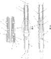
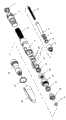
图4显示了图1的注射器的分解透视图;Figure 4 shows an exploded perspective view of the syringe of Figure 1;
图5显示了图1的注射器的剂量旋钮;Figure 5 shows the dose knob of the syringe of Figure 1;
图6显示了图1的注射器的离合器筒夹;Figure 6 shows the clutch cartridge of the syringe of Figure 1;
图7显示了图1的注射器的端部的部分横截面;Figure 7 shows a partial cross-section of the end of the syringe of Figure 1;
图8显示了图1的注射器的操作顺序;Figure 8 shows the sequence of operation of the syringe of Figure 1;
图9显示了通过注射器的可替换的内部结构的水平横截面,插入部显示了注射器的保持和触发器部分的放大视图;Figure 9 shows a horizontal cross-section through the alternative internal structure of the syringe, with the insert showing a magnified view of the retaining and trigger portion of the syringe;
图10显示了通过图9的可替换的注射器的垂直横截面;Figure 10 shows a vertical cross-section through the alternative syringe of Figure 9;
图11是图9的注射器的分解透视图;以及Figure 11 is an exploded perspective view of the syringe of Figure 9; and
图12显示了图9的注射器的驱动轴的端部的透视图。FIG. 12 shows a perspective view of the end of the drive shaft of the syringe of FIG. 9 .
具体实施方式Detailed ways
图1中显示了笔式注射器,所述笔式注射器具有用户可操作剂量设定机构。参照图2-7,可以看到,注射器包括壳体1和盖20,所述壳体1和盖20搭接配合在一起。特征环19被着色编码以指示将由注射器传递的药物的类型。螺纹在主体的上端设置在壳体1的内表面上。该内螺纹通过设置在剂量旋钮2的外表面上的外螺纹2a啮合。在图5中进行了详细显示了剂量旋钮2。壳体1之内的剂量旋钮2的纵向运动在两个方向上受到限制。盒壳体18固定到壳体1的下端,并安置成容纳一次性药物填充盒(未示出)。这样的盒具有橡胶盖,所述橡胶盖密封所述盒的一端,另外一端安置成容纳一次性针头。所述盒典型地是多种用途的,对于每次注射,用户都连接一个新的针。A pen injector with a user operable dose setting mechanism is shown in Figure 1 . Referring to Figures 2-7, it can be seen that the syringe comprises a
扭转弹簧4同轴地安置在壳体1内,并被安置成从被加载的盒提供用于注射药物的驱动力。所述弹簧4在其上端固定到剂量旋钮2。在其下端,弹簧4通过与壳体1一体模制的保持环固定到壳体。A
通常圆柱形的棘齿驱动轴3延伸通过所述弹簧4的中心。所述轴3的放大端部分3a具有围绕其周边形成的三个弹性腿部3b,所述腿部围绕所述轴等角度分开。在每个腿部的最外端部处,设置所述齿3c。所述齿3c啮合围绕大致圆柱形的驱动齿轮部件11的内表面形成的齿条11a(图4中不可见),所述大致圆柱形的驱动齿轮部件11在固定的轴向位置上坐落在所述壳体1之内。所述驱动齿轮部件11具有围绕下外表面部分形成的第二带齿齿条11b。这种齿条坐落在对应尺寸的齿条12a之内,所述齿条12a形成在所述保持环12的内表面上。所述保持环12与触发器12b一起形成,所述部件可滑动地安置在形成于所述壳体1之内的槽中,所述部件与所述主体分开一对止推垫圈10。弹簧13在向上的方向上推动触发器,在没有用户力施加在触发器的情况下、将所述齿条11b、12a保持在锁定啮合中。A generally cylindrical
进一步考虑棘齿驱动轴3,这在其下端处连接到离合器筒夹5。显示在图6中(从A之上和B之下观察)的离合器筒夹随着驱动轴3一起旋转,并设有一对弹性指5a。弹性指横截面被成形为设置用于啮合围绕剂量旋钮2的内表面形成的齿条2c的齿的各个齿。所述指5a向外偏压。Considering further the
重绕按钮6安置在剂量旋钮2之内,从所述剂量旋钮2伸出。所述按钮6连接到棘齿驱动轴3,随着驱动轴一起旋转但是能够在驱动轴之内纵向地滑动。弹簧7在按钮6和驱动轴3之间连接并将按钮相对于壳体1向外偏压。按钮6的下部通常是十字形的,十字的两个相对的臂与离合器筒夹5的弹性指5a相对。这些臂向内成锥化,这样当按钮处于其外部位置中时、这些臂防止弹性指5a的任何径向向内屈曲,同时允许当按钮利用按钮弹簧7的偏压而完全压缩时向内屈曲。该布置在图7中得到最佳显示,而图7A显示了在适当位置的按钮6,同时图7B显示了沿着按钮6所取的横截面的注射器的端部。A
导杆8具有沿着导杆的外表面的长度形成的螺纹。导杆安置在棘齿驱动轴3之内,且与形成在驱动齿轮11的内表面上的互补螺纹啮合。从棘齿驱动轴3伸出的导杆8具有固定到其上的导杆盖。导杆相对于驱动轴的旋转运动通过沿着导杆的长度所形成的凹部与设置在锁定套筒14的内表面上的互补花键的接合而得以防止。该锁定套筒保持在中间体室17之内,所述中间体室17本身通过一对互补的螺纹固定到壳体1的端部。在与药物容纳盒连接时,所述盒压缩杯16将压缩弹簧15并将载荷传递到锁定套筒14上。锁定套筒的有齿边缘与所述壳体1的匹配特征接合,防止锁定套筒旋转并确保当在释放驱动齿轮11之后旋转时、导杆8向前移动。The
分度指6a按钮6的内表面下垂。所述分度指在其端部处设有斜面形状的齿6b,所述斜面形状的齿6b具有垂直的、阻挡表面以及倾斜的驱动表面。当所述按钮压入剂量旋钮2中时,所述齿6b啮合围绕剂量旋钮2的内表面形成的分度齿条2b的齿。The inner surface of the
显示在图1-8中的带参考数字的部件的完整列表包含在下述的表1中。A complete listing of the numbered components shown in Figures 1-8 is contained in Table 1 below.
现在考虑注射器的操作,用户通过在顺时针的方向上旋转剂量旋钮2而设定剂量。当旋转剂量旋钮2时,弹簧4的顶部随着其一起旋转,产生了弹簧的扭转。在棘齿驱动轴3的顶部处的弹性指5a与形成在剂量旋钮2的内表面上的齿条2c的啮合也导致棘齿驱动轴3旋转。在棘齿驱动轴3的下端处,弹性腿部3b的齿3c围绕齿条11a的齿“点按”。所述齿与齿条11a的啮合防止弹簧4在每次点按之后松开。每次点按对应于弹簧的预限定的角向旋转,因此对应于预限定的喷射剂量。在剂量设定动作期间,显然可以理解的是,驱动齿轮11没有旋转,因此不会引起导杆8的轴向运动。因此,在剂量设定操作期间(或者由于后部填充所导致的引入空气),没有药物从所述盒喷射。Considering now the operation of the syringe, the user sets the dose by turning the
当用户将向下的力施加到触发器12b上时,这将触发器12b和驱动齿轮11的齿条脱离接合。这让驱动齿轮11和扭转弹簧4自由旋转。当驱动齿轮11围绕导杆8旋转时,导杆通过驱动齿轮向下驱动,导致导杆盖9向下推动盒的盖通过盒体,使药物从所述盒通过连接的注射器排出。When the user applies downward force to the trigger 12b, this disengages the trigger 12b and the rack of the
在用户过度设定剂量,即过旋转所述剂量旋钮2的情况下,用户利用偏压弹簧7的作用而将按钮6完全挤压到剂量旋钮2中。当按下按钮6时,所述齿6b的驱动表面与形成在分度齿2b上的齿中的一个齿接触(从图8A的开始位置到图8B中所示的位置)。进一步的压力在剂量旋钮2上沿着逆时针的方向引起旋转力直到到达图8C所示的完全按下位置。大体上同时,按钮6的十字形臂的向下运动导致弹性指5a自由地向内弯曲,让剂量旋钮2和弹簧4在储存在弹簧中的力和由齿所引起的力中的一个或者二者的作用下自由旋转。剂量旋钮2能够旋转直到所述齿的阻挡表面接合上齿条的下一个止动面。在此重设操作期间,棘齿驱动轴3和驱动齿轮11都没有旋转。因此,不会引起导杆8的任何轴向运动,且没有药物从所述盒喷射。通过临时将剂量旋钮和扭转弹簧从棘齿驱动轴分开而操作剂量重设机构,允许前者相对于驱动轴旋转。在从按钮6移除压力时,重绕按钮弹簧7将按钮返回到其最外的位置,由此弹性指5a的齿与齿条2c的齿再啮合。In case the user over-sets the dose, ie over-rotates said
现在将参照图9-12描述可替换的笔式注射器。从外部看,这种注射器具有与图1中所示的注射器相似的外观。该可替换的注射器的操作原理与图2-8的注射器的操作就剂量设定和发射功能而言是相似的。但是,剂量重设机构是不同的。An alternative pen injector will now be described with reference to Figures 9-12. Externally, this syringe has a similar appearance to the syringe shown in Figure 1 . The principle of operation of this alternative syringe is similar to that of the syringe of Figures 2-8 with regard to dose setting and firing functions. However, the dose reset mechanism is different.
所述注射器包括剂量设定旋钮2’,所述剂量设定旋钮2’通过互补的螺纹连接到壳体1’。剂量旋钮2’的端部由剂量旋钮盖7’闭合,所述剂量旋钮盖7’随着剂量旋钮一起旋转。现在考虑棘齿驱动轴3’,其具有带形成在其中的三个径向延伸槽(图12,图10A显示了棘齿保持器被移除的旋钮2,图12B显示了保持器被保持在位的旋钮,图12C显示了保持器就位但是显示为透明的旋钮)。这些槽容纳具有圆柱形主体的棘齿柱塞部件5’的相应臂5a’。所述主体紧紧地坐落在轴环3a’的端部中的圆形开口之内。每个臂5a’包括模制弹性体和端部齿,所述齿的表面以相同的角度倾斜。棘齿保持器6’搭接在轴环3a’的端部之上以将所述棘齿柱塞保持就位。所述棘齿柱塞的齿从它们各自的槽的端部伸出大约0.5mm,且可以由于模制弹簧的结果径向向内弯曲(大约0.25mm)。The syringe comprises a dose setting knob 2' connected to the housing 1' by complementary threads. The end of the dose knob 2' is closed by a dose knob cover 7' which rotates with the dose knob. Consider now the ratchet drive shaft 3', which has three radially extending slots with three radially extending slots formed therein (Figure 12, Figure 10A shows the
在组装好的注射器中,棘齿柱塞5’的齿啮合围绕驱动齿轮11’的内表面所形成的齿条。所述齿条的齿表面也是等角的,对应于棘齿柱塞的齿。In the assembled syringe, the teeth of the ratchet plunger 5' engage a rack formed around the inner surface of the drive gear 11'. The tooth surfaces of the rack are also conformal, corresponding to the teeth of the ratchet plunger.
显示在图9-12中的带参考数字的部件的完整列表包含在下述的表2中。A complete listing of the numbered components shown in Figures 9-12 is contained in Table 2 below.
在使用中,用户通过将剂量旋钮2’在顺时针方向旋转而拨动所述剂量。用户施加的力足以克服棘齿柱塞5’的齿和驱动齿轮11’的齿条的齿之间的阻力,所述驱动齿轮利用触发器12’的旋转而被保持就位。在该作用期间,棘齿柱塞的齿向内推动到棘齿驱动轴的端部轴环中以允许它们跨在驱动齿轮之内的齿条的齿之上。以同样的方式,如果用户希望减少设定的剂量,她或者他以逆时针的方向旋转所述剂量旋钮。棘齿柱塞齿的形状允许这样操作。这样,根据该设计,不需要重绕按钮与剂量旋钮分开,以方便剂量的重设。In use, the user dials the dose by turning the dose knob 2' in a clockwise direction. The force applied by the user is sufficient to overcome the resistance between the teeth of the ratchet plunger 5' and the teeth of the rack of the drive gear 11', which is held in place by the rotation of the trigger 12'. During this action, the teeth of the ratchet plunger are pushed inwardly into the end collar of the ratchet drive shaft to allow them to ride over the teeth of the rack within the drive gear. In the same way, if the user wishes to decrease the set dose, she or he turns the dose knob in a counterclockwise direction. The shape of the ratchet plunger teeth allows this. Thus, according to the design, there is no need for the rewind button to be separated from the dose knob to facilitate resetting of the dose.
普通技术人员显然理解,在不背离本发明的范围的情况下可对上述的实施例进行各种修改。It will be apparent to those of ordinary skill that various modifications may be made to the above-described embodiments without departing from the scope of the present invention.
表1Table 1
表2Table 2
Claims (18)
Translated fromChineseApplications Claiming Priority (3)
| Application Number | Priority Date | Filing Date | Title |
|---|---|---|---|
| GB0524604.6 | 2005-12-02 | ||
| GBGB0524604.6AGB0524604D0 (en) | 2005-12-02 | 2005-12-02 | Injection method and apparatus |
| PCT/GB2006/050416WO2007063342A1 (en) | 2005-12-02 | 2006-11-28 | Injection method and apparatus |
Publications (2)
| Publication Number | Publication Date |
|---|---|
| CN101321550A CN101321550A (en) | 2008-12-10 |
| CN101321550Btrue CN101321550B (en) | 2013-03-13 |
Family
ID=35685947
Family Applications (1)
| Application Number | Title | Priority Date | Filing Date |
|---|---|---|---|
| CN2006800453541AExpired - Fee RelatedCN101321550B (en) | 2005-12-02 | 2006-11-28 | Spraying methods and equipment |
Country Status (10)
| Country | Link |
|---|---|
| US (2) | US20070129687A1 (en) |
| EP (3) | EP2198906B1 (en) |
| JP (2) | JP5119164B2 (en) |
| CN (1) | CN101321550B (en) |
| DE (1) | DE602006019900D1 (en) |
| DK (1) | DK1954337T3 (en) |
| GB (1) | GB0524604D0 (en) |
| PL (1) | PL1954337T4 (en) |
| RU (1) | RU2395306C2 (en) |
| WO (1) | WO2007063342A1 (en) |
Cited By (1)
| Publication number | Priority date | Publication date | Assignee | Title |
|---|---|---|---|---|
| CN105517601A (en)* | 2013-09-10 | 2016-04-20 | 赛诺菲 | Drive mechanism for a drug delivery device |
Families Citing this family (121)
| Publication number | Priority date | Publication date | Assignee | Title |
|---|---|---|---|---|
| US6663602B2 (en) | 2000-06-16 | 2003-12-16 | Novo Nordisk A/S | Injection device |
| US20040098010A1 (en)* | 2001-10-22 | 2004-05-20 | Glenn Davison | Confuser crown skin pricker |
| WO2003068290A2 (en) | 2002-02-11 | 2003-08-21 | Antares Pharma, Inc. | Intradermal injector |
| US9486581B2 (en)* | 2002-09-11 | 2016-11-08 | Becton, Dickinson And Company | Injector device with force lock-out and injection rate limiting mechanisms |
| GB0409354D0 (en)* | 2004-04-27 | 2004-06-02 | Owen Mumford Ltd | Removal of needles |
| MX2007003682A (en) | 2004-10-04 | 2007-08-07 | Sanofi Aventis Deutschland | Drive mechanism for a drug delivery device. |
| ATE444090T1 (en) | 2004-10-21 | 2009-10-15 | Novo Nordisk As | SELECTION MECHANISM FOR A ROTARY PIN |
| HUE042286T2 (en) | 2005-01-24 | 2019-06-28 | Antares Pharma Inc | Needle-filled pre-filled syringe |
| GB0524604D0 (en)* | 2005-12-02 | 2006-01-11 | Owen Mumford Ltd | Injection method and apparatus |
| GB2434103B (en)* | 2006-01-12 | 2009-11-25 | Owen Mumford Ltd | Lancet firing device |
| WO2007131013A1 (en) | 2006-05-03 | 2007-11-15 | Antares Pharma, Inc. | Two-stage reconstituting injector |
| WO2007131025A1 (en) | 2006-05-03 | 2007-11-15 | Antares Pharma, Inc. | Injector with adjustable dosing |
| JP5253387B2 (en) | 2006-05-18 | 2013-07-31 | ノボ・ノルデイスク・エー/エス | Injection device with mode locking means |
| USD600795S1 (en)* | 2006-10-30 | 2009-09-22 | Sanofi-Aventis Deutschland Gmbh | Medical injector |
| CA121972S (en)* | 2007-02-23 | 2008-11-25 | Sanofi Aventis Deutschland | Medical injector |
| USD619702S1 (en)* | 2007-11-15 | 2010-07-13 | Tecpharma Licensing Ag | Medicine injector |
| US8992484B2 (en)* | 2008-01-23 | 2015-03-31 | Novo Nordisk A/S | Device for injecting apportioned doses of liquid drug |
| CA2711653C (en)* | 2008-01-23 | 2016-07-05 | Novo Nordisk A/S | Device for injecting apportioned doses of liquid drug |
| JP5451641B2 (en)* | 2008-02-07 | 2014-03-26 | ノボ・ノルデイスク・エー/エス | Injection device with mode defining element |
| EP3636301A1 (en) | 2008-03-10 | 2020-04-15 | Antares Pharma, Inc. | Injector safety device |
| US8376993B2 (en) | 2008-08-05 | 2013-02-19 | Antares Pharma, Inc. | Multiple dosage injector |
| GB2463034B (en)* | 2008-08-28 | 2012-11-07 | Owen Mumford Ltd | Autoinjection devices |
| CN102202712B (en)* | 2008-09-09 | 2013-07-31 | Shl集团有限责任公司 | Medicament delivery device |
| USD641077S1 (en) | 2008-09-15 | 2011-07-05 | Sanofi-Aventis Deutschland Gmbh | Medical injector |
| USD651305S1 (en) | 2008-10-11 | 2011-12-27 | Sanofi-Aventis Deutschland Gmbh | Medical injector |
| CA130178S (en) | 2008-10-11 | 2010-08-25 | Sanofi Aventis Deutschland | Medical injector |
| EP2373361B1 (en) | 2008-10-24 | 2012-09-12 | Novo Nordisk A/S | Dial-down mechanism for wind-up pen |
| GB2465390A (en) | 2008-11-17 | 2010-05-19 | Owen Mumford Ltd | Syringe needle cover remover |
| EP2198903A1 (en) | 2008-12-19 | 2010-06-23 | Sanofi-Aventis Deutschland GmbH | Motor mechanism for a drug delivery device and drug delivery device |
| EP2198904A1 (en) | 2008-12-19 | 2010-06-23 | Sanofi-Aventis Deutschland GmbH | Interlock mechanism for a drug delivery device and drug delivery device |
| BRPI1006948A2 (en)* | 2009-01-23 | 2016-04-12 | Sanofi Aventis Deutschland | drug identification system for multiple dose injection devices |
| US8529520B2 (en) | 2009-02-06 | 2013-09-10 | Shl Group Ab | Medicament delivery device with electronic dose sensor |
| JP5732039B2 (en) | 2009-03-20 | 2015-06-10 | アンタレス・ファーマ・インコーポレーテッド | Hazardous drug injection system |
| WO2010112565A1 (en) | 2009-03-31 | 2010-10-07 | Sanofi-Aventis Deutschland Gmbh | Dose button for a drug delivery device and method for manufacturing a dose button |
| US9457148B2 (en) | 2009-04-01 | 2016-10-04 | Shl Group Ab | Medicament delivery device |
| US8257319B2 (en)* | 2009-06-01 | 2012-09-04 | Sanofi-Aventis Deutschland Gmbh | Drug delivery device inner housing having helical spline |
| US8870831B2 (en) | 2009-08-24 | 2014-10-28 | Shl Group Ab | Dose reset mechanism |
| GB0918145D0 (en)* | 2009-10-16 | 2009-12-02 | Owen Mumford Ltd | Injector apparatus |
| PL215310B1 (en)* | 2009-10-30 | 2013-11-29 | Kappa Medilab Spolka Z Ograniczona Odpowiedzialnoscia | Automatic applicator, especially for insulin |
| USD685464S1 (en) | 2010-01-11 | 2013-07-02 | Sanofi-Aventis Deutschland Gmbh | Medical injector |
| WO2011101349A1 (en) | 2010-02-17 | 2011-08-25 | Sanofi-Aventis Deutschland Gmbh | Automatic injection device with torsional spring |
| JP5950828B2 (en)* | 2010-02-17 | 2016-07-13 | サノフィ−アベンティス・ドイチュラント・ゲゼルシャフト・ミット・ベシュレンクテル・ハフツング | Injection device |
| ES2484266T3 (en) | 2010-03-01 | 2014-08-11 | Eli Lilly And Company | Automatic injection device with delay mechanism including a double function thrust element |
| WO2011114343A1 (en)* | 2010-03-19 | 2011-09-22 | Pawan Trilokchand Agrawal | Multi dose parental drug delivery system with exchangeable glass cartridge |
| GB201004626D0 (en) | 2010-03-19 | 2010-05-05 | Owen Mumford Ltd | Improved injection device |
| CA2801147C (en)* | 2010-06-03 | 2015-02-24 | Shl Group Ab | Medicament delivery device |
| JP2013533078A (en)* | 2010-08-13 | 2013-08-22 | サノフィ−アベンティス・ドイチュラント・ゲゼルシャフト・ミット・ベシュレンクテル・ハフツング | Identification for drug delivery devices |
| GB201018827D0 (en) | 2010-11-08 | 2010-12-22 | Owen Mumford Ltd | Injection device |
| TWI464003B (en)* | 2010-11-18 | 2014-12-11 | Shl Group Ab | Medicament delivery device |
| USD717428S1 (en) | 2010-11-19 | 2014-11-11 | Sanofi-Aventis Deutschland Gmbh | Medical injector |
| USD725771S1 (en) | 2010-11-19 | 2015-03-31 | Sanofi-Aventis Deutschland Gmbh | Medical injector |
| USD717940S1 (en) | 2010-11-19 | 2014-11-18 | Sanofi-Aventis Deutschland Gmbh | Medical injector |
| USD722158S1 (en) | 2010-11-19 | 2015-02-03 | Sanofi-Aventis Deutschland Gmbh | Medical injector |
| EP2646078A1 (en)* | 2010-11-29 | 2013-10-09 | Sanofi-Aventis Deutschland GmbH | Drug delivery device |
| USD716442S1 (en) | 2010-12-06 | 2014-10-28 | Sanofi-Aventis Deutschland Gmbh | Medical injector |
| USD719257S1 (en) | 2010-12-06 | 2014-12-09 | Sanofi-Aventis Deutschland Gmbh | Medical injector |
| BR112013018905B1 (en) | 2011-01-24 | 2021-07-13 | Abbvie Biotechnology Ltd | AUTOMATIC INJECTION DEVICES THAT HAVE OVERMOLDED HANDLE SURFACES. |
| US9452265B2 (en) | 2011-03-18 | 2016-09-27 | Becton, Dickinson And Company | End of injection indicator for injection pen |
| WO2012154110A1 (en)* | 2011-05-12 | 2012-11-15 | Shl Group Ab | Medical delivery device with dose re-setting |
| USRE50423E1 (en)* | 2011-06-17 | 2025-05-13 | Shl Medical Ag | Injection device |
| US8496619B2 (en)* | 2011-07-15 | 2013-07-30 | Antares Pharma, Inc. | Injection device with cammed ram assembly |
| US9220660B2 (en) | 2011-07-15 | 2015-12-29 | Antares Pharma, Inc. | Liquid-transfer adapter beveled spike |
| USD734450S1 (en)* | 2011-11-01 | 2015-07-14 | Novo Nordisk A/S | Injection device |
| US9468722B2 (en)* | 2011-11-25 | 2016-10-18 | Shl Group Ab | Medicament delivery device |
| JP2015505253A (en)* | 2011-12-06 | 2015-02-19 | ノボ・ノルデイスク・エー/エス | Drive mechanism for an injection device and method of assembling an injection device comprising such a drive mechanism |
| JP6069351B2 (en) | 2011-12-29 | 2017-02-01 | ノボ・ノルデイスク・エー/エス | Torsion spring type automatic syringe with dial-up / dial-down administration mechanism |
| US8834449B2 (en) | 2012-01-23 | 2014-09-16 | Ikomed Technologies, Inc. | Mixing syringe |
| US9751056B2 (en) | 2012-01-23 | 2017-09-05 | Merit Medical Systems, Inc. | Mixing syringe |
| WO2013110538A1 (en) | 2012-01-27 | 2013-08-01 | Novo Nordisk A/S | Injection device with a sliding scale |
| PL220720B1 (en) | 2012-02-08 | 2015-12-31 | Copernicus Spółka Z Ograniczoną Odpowiedzialnością | Injection device with a reset mechanism of the dose |
| US9486583B2 (en) | 2012-03-06 | 2016-11-08 | Antares Pharma, Inc. | Prefilled syringe with breakaway force feature |
| IN2014DN07773A (en)* | 2012-03-15 | 2015-05-15 | Becton Dickinson Co | |
| EP2644218B2 (en)* | 2012-03-30 | 2022-11-02 | Tecpharma Licensing AG | Injection device with dose display and clockwork drive |
| EP4186545A1 (en) | 2012-04-06 | 2023-05-31 | Antares Pharma, Inc. | Needle assisted jet injection administration of testosterone compositions |
| US9364610B2 (en) | 2012-05-07 | 2016-06-14 | Antares Pharma, Inc. | Injection device with cammed ram assembly |
| US10195359B2 (en) | 2012-05-31 | 2019-02-05 | Novo Nordisk A/S | Dial-down mechanism for wind-up pen |
| CN202699777U (en)* | 2012-06-14 | 2013-01-30 | 甘肃成纪生物药业有限公司 | Adjustable injection pen |
| FI3659647T3 (en) | 2013-02-11 | 2024-03-28 | Antares Pharma Inc | NEEDLE-ASSISTED SPRAY INJECTOR WITH REDUCED TRIGGER FORCE |
| CA2905031C (en) | 2013-03-11 | 2018-01-23 | Hans PFLAUMER | Dosage injector with pinion system |
| WO2014165136A1 (en) | 2013-03-12 | 2014-10-09 | Antares Pharma, Inc. | Constant volume prefilled syringes and kits thereof |
| MX2015013058A (en) | 2013-03-14 | 2016-05-31 | Lilly Co Eli | Trigger assembly for an automatic injection device. |
| KR20150119092A (en) | 2013-03-14 | 2015-10-23 | 일라이 릴리 앤드 캄파니 | Delay mechanism suitable for compact automatic injection device |
| US10232118B2 (en)* | 2013-04-10 | 2019-03-19 | Sanofi | Drive assembly for a drug delivery device |
| WO2014166909A1 (en)* | 2013-04-10 | 2014-10-16 | Sanofi | Injection device |
| US10688248B2 (en)* | 2013-04-10 | 2020-06-23 | Sanofi | Injection device |
| EP2983768A1 (en)* | 2013-04-10 | 2016-02-17 | Sanofi | Drive mechanism of a drug delivery device |
| MX2015014293A (en) | 2013-04-10 | 2015-12-08 | Sanofi Sa | Injection device. |
| JP6419159B2 (en)* | 2013-04-10 | 2018-11-07 | サノフイSanofi | Injection device |
| GB2516071B (en) | 2013-07-10 | 2016-01-06 | Owen Mumford Ltd | Control of plunger position in an injection device |
| CN105682712B (en)* | 2013-09-03 | 2020-06-26 | 赛诺菲 | Mechanism for a drug delivery device and drug delivery device comprising the mechanism |
| TW201521810A (en)* | 2013-09-03 | 2015-06-16 | Sanofi Sa | Drive mechanism |
| GB2509348B (en)* | 2013-09-10 | 2016-03-30 | Owen Mumford Ltd | Leak prevention in injection device |
| CN105611959A (en)* | 2013-10-16 | 2016-05-25 | 诺和诺德股份有限公司 | Drug delivery device with improved dose reset mechanism |
| JP6566946B2 (en)* | 2013-11-22 | 2019-08-28 | サノフィ−アベンティス・ドイチュラント・ゲゼルシャフト・ミット・ベシュレンクテル・ハフツング | Drug delivery device having anti-counterfeit function |
| TW201611853A (en) | 2014-07-01 | 2016-04-01 | Sanofi Sa | Injection device |
| WO2016055505A1 (en) | 2014-10-08 | 2016-04-14 | Novo Nordisk A/S | A torsion spring for an injection device and an injection device comprising such torsion spring |
| TW201622762A (en)* | 2014-10-09 | 2016-07-01 | 賽諾菲公司 | Insert and drug delivery device herewith |
| US10576212B2 (en)* | 2014-12-08 | 2020-03-03 | Sanofi | Dose setting mechanism and drug delivery device herewith |
| JP6815650B2 (en)* | 2015-04-16 | 2021-01-20 | 株式会社根本杏林堂 | Chemical injection device, control method of chemical injection device, computer program |
| PL414382A1 (en) | 2015-10-15 | 2017-04-24 | Copernicus Spółka Z Ograniczoną Odpowiedzialnością | Setting mechanism, in particular for dosing |
| PL414383A1 (en) | 2015-10-15 | 2017-04-24 | Copernicus Spółka Z Ograniczoną Odpowiedzialnością | Setting mechanism, in particular for dosing pharmaceuticals |
| WO2017070959A1 (en)* | 2015-10-30 | 2017-05-04 | 项文 | Device for controlling puncture depth and hiding needle and usage method thereof |
| EP3368105B1 (en)* | 2015-10-30 | 2020-07-01 | Novo Nordisk A/S | Method of manufacturing prefilled drug delivery devices |
| PL227678B1 (en) | 2015-12-22 | 2018-01-31 | Copernicus Spolka Z Ograniczona Odpowiedzialnoscia | Control and drive system for the device intended for injection and the device for making injections equipped with such a system |
| PL3108914T3 (en) | 2016-07-07 | 2019-08-30 | Copernicus Sp. Z O.O. | Injection device for delivering a defined number of equal doses of a liquid substance |
| CN106037829B (en)* | 2016-07-15 | 2023-07-28 | 沈阳何氏眼科医院有限公司 | Ocular surface cell sampling system |
| GB201615447D0 (en) | 2016-09-12 | 2016-10-26 | Norton Healthcare Ltd | Dose delivery mechanism |
| GB201615433D0 (en) | 2016-09-12 | 2016-10-26 | Norton Healthcare Ltd | Dose setting and display mechanism |
| RU2653688C1 (en)* | 2017-01-19 | 2018-05-11 | Бектон, Дикинсон Энд Компани | Disposable syringe-pen for several doses |
| CN107050575B (en)* | 2017-04-24 | 2023-02-24 | 无锡市馨亿生物医疗科技有限公司 | Pen type injector capable of being repeatedly used |
| PL3399215T3 (en)* | 2017-05-05 | 2021-01-25 | Eppendorf Ag | Spindle drive |
| EP3399214B1 (en)* | 2017-05-05 | 2020-07-15 | Eppendorf AG | Electronic dosing drive |
| JP7200134B2 (en) | 2017-06-08 | 2023-01-06 | アムジエン・インコーポレーテツド | Torque driven drug delivery device |
| PL232651B1 (en) | 2017-07-18 | 2019-07-31 | Copernicus Spolka Z Ograniczona Odpowiedzialnoscia | Coupling with locking system for the medical injecting device |
| EP3717045A1 (en)* | 2017-11-27 | 2020-10-07 | Sanofi | Ratchet systems for drug delivery devices |
| US11439500B2 (en)* | 2018-12-20 | 2022-09-13 | Alcon Inc. | IOL injector with automatic driver or assisted manual drive force |
| US11235107B2 (en)* | 2019-07-23 | 2022-02-01 | Solteam Incorporation | Medical injection system |
| USD926973S1 (en) | 2019-09-05 | 2021-08-03 | Novo Nordisk A/S | Injection device |
| USD996605S1 (en) | 2021-03-29 | 2023-08-22 | Owen Mumford Limited | Injector |
| CN114470442A (en)* | 2022-03-02 | 2022-05-13 | 康希诺生物股份公司 | Pen-shaped drug delivery device for aerosol inhalation |
| US20230398306A1 (en)* | 2022-06-10 | 2023-12-14 | Medmix Switzerland Ag | Set of a medicament delivery device and a cover |
Citations (2)
| Publication number | Priority date | Publication date | Assignee | Title |
|---|---|---|---|---|
| US5584815A (en)* | 1993-04-02 | 1996-12-17 | Eli Lilly And Company | Multi-cartridge medication injection device |
| CN1509193A (en)* | 2001-01-05 | 2004-06-30 | ŵ��Ų�ڿ˹�˾ | Automatic injection device with reset feature |
Family Cites Families (185)
| Publication number | Priority date | Publication date | Assignee | Title |
|---|---|---|---|---|
| US930477A (en)* | 1908-08-08 | 1909-08-10 | William Henry Hudson | Trephine. |
| DE1049188B (en) | 1954-06-19 | 1959-01-22 | Hell Rudolf Dr Ing Fa | Gear for converting a reciprocating movement into a periodically advancing movement |
| US3659608A (en)* | 1969-12-15 | 1972-05-02 | Damon Corp | Snap-acting surgical lancet |
| US3620209A (en)* | 1970-05-08 | 1971-11-16 | Harvey Kravitz | Device for reducing the pain of injections of medicines and other biologicals |
| US3698395A (en)* | 1971-03-12 | 1972-10-17 | Harrith M Hasson | Surgical closure |
| US3760809A (en) | 1971-10-22 | 1973-09-25 | Damon Corp | Surgical lancet having casing |
| DE3011211A1 (en)* | 1980-03-22 | 1981-10-01 | Clinicon Mannheim GmbH, 6800 Mannheim | BLOOD PLANT DEVICE FOR TAKING BLOOD FOR DIAGNOSTIC PURPOSES |
| US4535769A (en)* | 1981-03-23 | 1985-08-20 | Becton, Dickinson And Company | Automatic retractable lancet assembly |
| US4449529A (en)* | 1981-11-18 | 1984-05-22 | Becton Dickinson And Company | Automatic retractable lancet assembly |
| JPS58142028A (en)* | 1982-02-13 | 1983-08-23 | Fumiaki Hasegawa | Torque limiter |
| JPS58185230U (en)* | 1982-06-04 | 1983-12-09 | テルモ株式会社 | indwelling needle |
| EP0097748A1 (en) | 1982-06-28 | 1984-01-11 | Gérard Joseph Slama | Pricking device for collecting a droplet of blood |
| US4462405A (en)* | 1982-09-27 | 1984-07-31 | Ehrlich Joseph C | Blood letting apparatus |
| USRE32922E (en)* | 1983-01-13 | 1989-05-16 | Paul D. Levin | Blood sampling instrument |
| US4517978A (en)* | 1983-01-13 | 1985-05-21 | Levin Paul D | Blood sampling instrument |
| USD281383S (en)* | 1983-05-25 | 1985-11-19 | Daniel E. Gelles Associates, Inc. | Article display bracket |
| NZ208203A (en) | 1983-09-15 | 1988-03-30 | Becton Dickinson Co | Blood lancet and shield: lancet has three cutting edges terminating in a point |
| GB8406154D0 (en) | 1984-03-09 | 1984-04-11 | Palmer G C | Sampling fluid |
| US4646753A (en)* | 1985-06-11 | 1987-03-03 | Becton, Dickinson And Company | Blood collector for microcollection container |
| US4653513A (en)* | 1985-08-09 | 1987-03-31 | Dombrowski Mitchell P | Blood sampler |
| FR2596278B2 (en)* | 1986-03-27 | 1989-07-13 | Micro Mega Sa | DENTAL SYRINGE FOR INTRA-LIGAMENTARY INJECTIONS |
| DE3730469A1 (en) | 1986-09-08 | 1988-06-16 | Wolfgang Dr Med Wagner | Device for suction diagnosis or suction injection |
| DE3635163A1 (en)* | 1986-10-16 | 1988-05-05 | Walterscheid Gmbh Jean | OVERLOAD CLUTCH FOR SECURING DRIVE GEARS, ESPECIALLY ON AGRICULTURAL MACHINERY |
| DE3715337C2 (en) | 1986-11-14 | 1994-04-14 | Haselmeier Wilhelm Fa | Injection device |
| GB8713810D0 (en) | 1987-06-12 | 1987-07-15 | Hypoguard Uk Ltd | Measured dose dispensing device |
| US4858607A (en)* | 1987-10-16 | 1989-08-22 | Pavel Jordan & Associates | Plastic device for injection and obtaining blood samples |
| DK166948B1 (en) | 1988-02-10 | 1993-08-09 | Dcp Af 1988 As | DOSING UNIT FOR DOSING A NUMBER OF MEASURED QUANTITIES OF A FLUID, SUCH AS INSULIN, FROM A GLASS STUBLE |
| GB8809115D0 (en)* | 1988-04-18 | 1988-05-18 | Turner R C | Syringes |
| US4917243A (en)* | 1988-08-16 | 1990-04-17 | The Board Of Regents, University Of Texas System | Needle disposal device |
| USD327214S (en)* | 1988-08-30 | 1992-06-23 | El Barador Holding Pty. Ltd. | Bracket for anchoring posts, wall panels or the like |
| US4902279A (en)* | 1988-10-05 | 1990-02-20 | Autoject Systems Inc. | Liquid medicament safety injector |
| US4967763A (en)* | 1989-03-13 | 1990-11-06 | Becton, Dickinson And Company | Platelet stable blood collection assembly |
| US5054499A (en)* | 1989-03-27 | 1991-10-08 | Swierczek Remi D | Disposable skin perforator and blood testing device |
| AR240622A1 (en)* | 1989-06-01 | 1990-06-30 | Mostarda Jorge Fernando Brizue | Apparatus for extracting the hypodermic needle from the syringe |
| US5226895A (en)* | 1989-06-05 | 1993-07-13 | Eli Lilly And Company | Multiple dose injection pen |
| IL90545A (en)* | 1989-06-06 | 1994-07-31 | Orbot Systems Ltd | Immobilizing device for printed-circuit boards |
| USD322211S (en) | 1989-06-09 | 1991-12-10 | Gary Products Group, Inc. | Bracket for decorative lighting |
| US5026388A (en)* | 1989-09-26 | 1991-06-25 | Ingalz Thomas J | Single-use skin puncture device |
| WO1991008786A1 (en) | 1989-12-18 | 1991-06-27 | Wayne Crawford | Hypodermic needle sheath |
| DK17890A (en) | 1990-01-22 | 1991-07-23 | Novo Nordisk As | METHOD AND APPARATUS FOR MIXTURE AND INJECTION OF A MEDICINE |
| USD327321S (en)* | 1990-03-19 | 1992-06-23 | Infection Control Products, Inc. | Cannula protecting shield |
| US5226896A (en)* | 1990-04-04 | 1993-07-13 | Eli Lilly And Company | Dose indicating injection pen |
| US5104388A (en)* | 1990-05-08 | 1992-04-14 | Fbk International Corporation | Membrane splittable tubing |
| US5116353B1 (en)* | 1990-10-05 | 1996-09-10 | Digital Voice Systems Inc | Safety trocar |
| DE4112259A1 (en)* | 1991-04-15 | 1992-10-22 | Medico Dev Investment Co | INJECTION DEVICE |
| US5147306A (en)* | 1991-07-01 | 1992-09-15 | Gubich Stephen J | Device for puckering the flesh to facilitate injections |
| US5402798A (en)* | 1991-07-18 | 1995-04-04 | Swierczek; Remi | Disposable skin perforator and blood testing device |
| US5242421A (en)* | 1991-08-06 | 1993-09-07 | Chan Mark S H | Needle cap |
| DK175491D0 (en)* | 1991-10-18 | 1991-10-18 | Novo Nordisk As | APPARATUS |
| US5279585A (en)* | 1992-02-04 | 1994-01-18 | Becton, Dickinson And Company | Medication delivery pen having improved dose delivery features |
| JP2572823Y2 (en) | 1992-02-13 | 1998-05-25 | 株式会社アドバンス | Simple blood sampler |
| DE4205036C1 (en)* | 1992-02-19 | 1993-06-17 | Henke-Sass, Wolf Gmbh, 7200 Tuttlingen, De | Injection cylinder for subcutaneous vaccination - comprises first hollow cylindrical tube in which is fitted telescopically second tube with reduced dia. |
| GB9207120D0 (en)* | 1992-04-01 | 1992-05-13 | Owen Mumford Ltd | Improvements relating to blood sampling devices |
| CA2079192C (en)* | 1992-09-25 | 1995-12-26 | Bernard Strong | Combined lancet and multi-function cap and lancet injector for use therewith |
| US5320609A (en)* | 1992-12-07 | 1994-06-14 | Habley Medical Technology Corporation | Automatic pharmaceutical dispensing syringe |
| GB9226423D0 (en)* | 1992-12-18 | 1993-02-10 | Sams Bernard | Incrementing mechanisms |
| US5472433A (en) | 1992-12-22 | 1995-12-05 | Suzuki; George R. | Disposable safety guard for syringe needles and the like |
| US5353806A (en)* | 1993-03-04 | 1994-10-11 | The Venture Fund Of Washington | Liquid collection device |
| US5383865A (en) | 1993-03-15 | 1995-01-24 | Eli Lilly And Company | Medication dispensing device |
| ZA941881B (en)* | 1993-04-02 | 1995-09-18 | Lilly Co Eli | Manifold medication injection apparatus and method |
| JP2630197B2 (en)* | 1993-04-28 | 1997-07-16 | 株式会社ニッショー | Blood suction device |
| US5749886A (en)* | 1993-06-18 | 1998-05-12 | Leonard Bloom | Disposable guarded finger scalpel for inserting a line in a patient and blade therefor |
| DE4320463A1 (en)* | 1993-06-21 | 1994-12-22 | Boehringer Mannheim Gmbh | Blood lancet device for drawing blood for diagnostic purposes |
| WO1995006240A1 (en) | 1993-08-24 | 1995-03-02 | Metrika Laboratories, Inc. | Novel disposable electronic assay device |
| US5837546A (en)* | 1993-08-24 | 1998-11-17 | Metrika, Inc. | Electronic assay device and method |
| US5439473A (en)* | 1993-12-13 | 1995-08-08 | Modulohm A/S | Safety lancet |
| US5514097A (en)* | 1994-02-14 | 1996-05-07 | Genentech, Inc. | Self administered injection pen apparatus and method |
| US5454828A (en)* | 1994-03-16 | 1995-10-03 | Schraga; Steven | Lancet unit with safety sleeve |
| US5439453A (en)* | 1994-03-25 | 1995-08-08 | Kashanchi; Behnam | Hypodermic needle storage apparatus |
| US5527296A (en)* | 1994-03-25 | 1996-06-18 | Kashanchi; Behnam | Hypodermic needle storage apparatus |
| US5527513A (en)* | 1994-04-08 | 1996-06-18 | Becton Dickinson And Company | Collection assembly |
| US5529581A (en)* | 1994-05-17 | 1996-06-25 | International Technidyne Corporation | Lancet device for creating a skin incision |
| USD362064S (en)* | 1994-06-02 | 1995-09-05 | Smick Ronald H | I.V. needle insertion guide |
| US5725508A (en)* | 1994-06-22 | 1998-03-10 | Becton Dickinson And Company | Quick connect medication delivery pen |
| US5827232A (en) | 1994-06-22 | 1998-10-27 | Becton Dickinson And Company | Quick connect medication delivery pen |
| US5547702A (en)* | 1994-07-08 | 1996-08-20 | Polymer Technology International Corporation | Method for continuous manufacture of diagnostic test strips |
| GB9418122D0 (en) | 1994-09-08 | 1994-10-26 | Owen Mumford Ltd | Improvements relating to injection devices |
| JP3614943B2 (en)* | 1994-09-29 | 2005-01-26 | オリンパス株式会社 | Endoscopic puncture needle |
| GB9422260D0 (en)* | 1994-11-04 | 1994-12-21 | Owen Mumford Ltd | Improvements relating to skin prickers |
| US5628764A (en)* | 1995-03-21 | 1997-05-13 | Schraga; Steven | Collar lancet device |
| US5569286A (en) | 1995-03-29 | 1996-10-29 | Becton Dickinson And Company | Lancet assembly |
| US5479886A (en)* | 1995-05-12 | 1996-01-02 | Cummins Engine | Engine oil capacitor |
| KR0135178Y1 (en)* | 1995-06-26 | 1999-03-20 | 김인환 | Blood collection lancet |
| WO1997004707A1 (en) | 1995-07-28 | 1997-02-13 | Apls Co., Ltd. | Assembly for adjusting piercing depth of lancet |
| DE29514084U1 (en) | 1995-09-01 | 1995-11-02 | Biosafe Diagnostics Corp., Lincolnshire, Ill. | Blood collection and test device |
| US5879367A (en)* | 1995-09-08 | 1999-03-09 | Integ, Inc. | Enhanced interstitial fluid collection |
| US5609577A (en)* | 1996-01-29 | 1997-03-11 | Haber; Terry M. | Automatically locking hypodermic needle hiding shield for a dose metering syringe |
| US6332871B1 (en) | 1996-05-17 | 2001-12-25 | Amira Medical | Blood and interstitial fluid sampling device |
| US5951493A (en)* | 1997-05-16 | 1999-09-14 | Mercury Diagnostics, Inc. | Methods and apparatus for expressing body fluid from an incision |
| US5879311A (en)* | 1996-05-17 | 1999-03-09 | Mercury Diagnostics, Inc. | Body fluid sampling device and methods of use |
| US5613978A (en)* | 1996-06-04 | 1997-03-25 | Palco Laboratories | Adjustable tip for lancet device |
| GB9616953D0 (en) | 1996-08-13 | 1996-09-25 | Owen Mumford Ltd | Improvements relating to skin prickers |
| GB9619462D0 (en) | 1996-09-18 | 1996-10-30 | Owen Mumford Ltd | Improvements relating to lancet devices |
| US5797942A (en)* | 1996-09-23 | 1998-08-25 | Schraga; Steven | Re-usable end cap for re-usable lancet devices for removing and disposing of a contaminated lancet |
| ES2186003T3 (en)* | 1996-10-30 | 2003-05-01 | Amira Medical | SYNCHRONIZED ANALYZE ANALYSIS SYSTEM. |
| US6027459A (en)* | 1996-12-06 | 2000-02-22 | Abbott Laboratories | Method and apparatus for obtaining blood for diagnostic tests |
| US5910147A (en)* | 1996-12-31 | 1999-06-08 | Donald J. Ersler | Angled replaceable comedone extractor |
| US6277097B1 (en)* | 1997-03-25 | 2001-08-21 | Novo Nordisk A/S | Injection system |
| US5916230A (en)* | 1997-06-16 | 1999-06-29 | Bayer Corporation | Blood sampling device with adjustable end cap |
| US6056765A (en)* | 1997-06-24 | 2000-05-02 | Bajaj; Ratan | Lancet device |
| GB9716065D0 (en) | 1997-07-31 | 1997-10-01 | Owen Mumford Ltd | Improvements relating to injection devices |
| US5921966A (en) | 1997-08-11 | 1999-07-13 | Becton Dickinson And Company | Medication delivery pen having an improved clutch assembly |
| US5964718A (en)* | 1997-11-21 | 1999-10-12 | Mercury Diagnostics, Inc. | Body fluid sampling device |
| US5871494A (en)* | 1997-12-04 | 1999-02-16 | Hewlett-Packard Company | Reproducible lancing for sampling blood |
| JP2000014662A (en)* | 1998-01-22 | 2000-01-18 | Terumo Corp | Humor examination device |
| CZ297361B6 (en) | 1998-01-30 | 2006-11-15 | Novo Nordisk A/S | Injection syringe |
| US6248095B1 (en)* | 1998-02-23 | 2001-06-19 | Becton, Dickinson And Company | Low-cost medication delivery pen |
| US6106539A (en)* | 1998-04-15 | 2000-08-22 | Neosurg Technologies | Trocar with removable, replaceable tip |
| GB9808408D0 (en) | 1998-04-18 | 1998-06-17 | Owen Mumford Ltd | Improvements relating to injection devices |
| US6053930A (en)* | 1998-05-11 | 2000-04-25 | Ruppert; Norbert | Single use lancet assembly |
| DE19821934C1 (en) | 1998-05-15 | 1999-11-11 | Disetronic Licensing Ag | Device for the dosed administration of an injectable product |
| DE19830604C2 (en)* | 1998-07-09 | 2000-06-21 | November Ag Molekulare Medizin | Device for perforating skin |
| USD421214S (en)* | 1998-08-25 | 2000-02-29 | Koros Tibor B | Detachable clamp for a rotatable retractor blade |
| DE19838760A1 (en)* | 1998-08-26 | 2000-04-20 | Bauer Jlona | Injection unit, especially for injecting medicines such as insulin, consists of a housing with a chamber for holding a needle, a cartridge and a release mechanism. |
| US6210420B1 (en)* | 1999-01-19 | 2001-04-03 | Agilent Technologies, Inc. | Apparatus and method for efficient blood sampling with lancet |
| GB9903475D0 (en)* | 1999-02-17 | 1999-04-07 | Owen Mumford Ltd | Improvements relating to injection devices |
| US6197040B1 (en)* | 1999-02-23 | 2001-03-06 | Lifescan, Inc. | Lancing device having a releasable connector |
| JP3361470B2 (en) | 1999-03-02 | 2003-01-07 | アプルス株式会社 | Lancet device for forming precisely controlled incidents |
| DE19909602A1 (en)* | 1999-03-05 | 2000-09-07 | Roche Diagnostics Gmbh | Device for drawing blood for diagnostic purposes |
| US6306152B1 (en)* | 1999-03-08 | 2001-10-23 | Agilent Technologies, Inc. | Lancet device with skin movement control and ballistic preload |
| US6132449A (en)* | 1999-03-08 | 2000-10-17 | Agilent Technologies, Inc. | Extraction and transportation of blood for analysis |
| US6152942A (en)* | 1999-06-14 | 2000-11-28 | Bayer Corporation | Vacuum assisted lancing device |
| US6558402B1 (en)* | 1999-08-03 | 2003-05-06 | Becton, Dickinson And Company | Lancer |
| GB9919681D0 (en) | 1999-08-19 | 1999-10-20 | Owen Mumsford Limited | Improvements relating to medical injectors and skin prickers |
| US6319209B1 (en) | 1999-08-23 | 2001-11-20 | European Institute Of Science | Disposable test vial with sample delivery device for dispensing sample into a reagent |
| TW453884B (en)* | 1999-09-16 | 2001-09-11 | Novo Nordisk As | Dose setting limiter |
| USD446107S1 (en)* | 1999-09-30 | 2001-08-07 | Douglas M. Carter | Deadbolt security plate |
| US6283982B1 (en)* | 1999-10-19 | 2001-09-04 | Facet Technologies, Inc. | Lancing device and method of sample collection |
| AU1889001A (en) | 1999-12-13 | 2001-06-18 | Arkray, Inc. | Body fluid measuring apparatus with lancet and lancet holder used for the measuring apparatus |
| DE10002748B4 (en)* | 2000-01-22 | 2006-05-18 | Robert Bosch Gmbh | Hand tool with a safety clutch |
| GB0003991D0 (en) | 2000-02-22 | 2000-04-12 | Owen Mumford Ltd | Improvements relating to skin prickers |
| US6706159B2 (en)* | 2000-03-02 | 2004-03-16 | Diabetes Diagnostics | Combined lancet and electrochemical analyte-testing apparatus |
| GB0007071D0 (en)* | 2000-03-24 | 2000-05-17 | Sams Bernard | One-way clutch mechanisms and injector devices |
| US6607508B2 (en)* | 2000-04-27 | 2003-08-19 | Invivotech, Inc. | Vial injector device |
| RU2269954C2 (en) | 2000-06-09 | 2006-02-20 | Дайэбитиз Дайэгностикс, Инк. | Cap for lancet device for punching dermal tissue (versions), cap for lancet device for punching tip of finger, cap for lancet device for punching curvilinear dermal tissue and lancet device for punching dermal tissue |
| US6663602B2 (en)* | 2000-06-16 | 2003-12-16 | Novo Nordisk A/S | Injection device |
| US6561989B2 (en) | 2000-07-10 | 2003-05-13 | Bayer Healthcare, Llc | Thin lance and test sensor having same |
| AU2001283518A1 (en)* | 2000-07-31 | 2002-02-13 | Bionix Development Corporation | Method for controlling the pain from injections or minor surgical procedures andapparatus for use therewith |
| DE10046279A1 (en)* | 2000-09-19 | 2002-04-04 | Disetronic Licensing Ag | Device for the dosed administration of an injectable product |
| CN1268405C (en) | 2000-10-09 | 2006-08-09 | 伊莱利利公司 | Pen device for administration of parathyroid hormone |
| US6491709B2 (en)* | 2000-12-22 | 2002-12-10 | Becton, Dickinson And Company | Alternate-site lancer |
| EP1396226B1 (en) | 2001-06-11 | 2013-08-21 | ARKRAY, Inc. | Measuring apparatus comprising a puncturing element integration mounting body |
| US6645219B2 (en)* | 2001-09-07 | 2003-11-11 | Amira Medical | Rotatable penetration depth adjusting arrangement |
| USD470391S1 (en)* | 2001-10-12 | 2003-02-18 | Reese Products, Inc. | Sway control bracket |
| US20040098010A1 (en)* | 2001-10-22 | 2004-05-20 | Glenn Davison | Confuser crown skin pricker |
| US6616640B2 (en)* | 2002-01-07 | 2003-09-09 | Marina Ling-Ko Chen | Syringe with plunger anti-detachment mechanism |
| DE10206254A1 (en)* | 2002-02-15 | 2003-08-28 | Roche Diagnostics Gmbh | System for taking pain-free blood |
| GB0211294D0 (en) | 2002-05-17 | 2002-06-26 | Owen Mumford Ltd | Improvements relating to injection devices |
| DE10229138B4 (en) | 2002-06-28 | 2008-01-31 | Tecpharma Licensing Ag | Product diverter with piston rod emergency reset |
| US6945961B2 (en)* | 2002-07-10 | 2005-09-20 | Novo Nordisk A/S | Injection device |
| DE10240165A1 (en) | 2002-08-30 | 2004-03-18 | Disetronic Licensing Ag | Dispensing unit for use in infusion pumps comprises reservoir for infusion liquid fitted with spring-loaded piston, toothed wheel cooperating with locking bar to prevent piston moving |
| US6755805B1 (en)* | 2002-09-13 | 2004-06-29 | Alan Reid | Needle device having enhanced safety |
| JP4448448B2 (en)* | 2002-09-24 | 2010-04-07 | エス・ホー・エル・グループ・アクチボラゲット | Injection device |
| US20040162573A1 (en)* | 2003-02-19 | 2004-08-19 | Kheiri Mohammad A. | Endcap for lancing device and method of use |
| GB0304822D0 (en)* | 2003-03-03 | 2003-04-09 | Dca Internat Ltd | Improvements in and relating to a pen-type injector |
| GB0306642D0 (en)* | 2003-03-22 | 2003-04-30 | Dca Design Int Ltd | Improvements in and relating to an injector for a medical product |
| US6932794B2 (en) | 2003-04-03 | 2005-08-23 | Becton, Dickinson And Company | Medication delivery pen |
| WO2005011496A1 (en) | 2003-07-31 | 2005-02-10 | Matsushita Electric Industrial Co., Ltd. | Puncturing instrument, puncturing needle cartridge, puncturing instrument set, and puncturing needle discardment instrument |
| GB0318366D0 (en) | 2003-08-06 | 2003-09-10 | Owen Mumford Ltd | Improvements relating to blood sampling devices |
| US7905898B2 (en)* | 2003-08-15 | 2011-03-15 | Stat Medical Devices, Inc. | Adjustable lancet device and method |
| GB0320283D0 (en) | 2003-08-29 | 2003-10-01 | Owen Mumford Ltd | Improvements relating to lancets |
| DE20317377U1 (en)* | 2003-11-03 | 2005-03-17 | B D Medico S A R L | injection device |
| USD516218S1 (en)* | 2004-04-15 | 2006-02-28 | Larocca Robert J | Wrist device |
| GB0409354D0 (en) | 2004-04-27 | 2004-06-02 | Owen Mumford Ltd | Removal of needles |
| CN100443049C (en) | 2004-05-17 | 2008-12-17 | 泉株式会社 | Lancet Components |
| WO2005117721A2 (en) | 2004-05-27 | 2005-12-15 | Facet Technologies, Llc | Low-cost lancing device with cantilevered leaf spring for launch and return |
| US7727166B2 (en) | 2004-07-26 | 2010-06-01 | Nova Biomedical Corporation | Lancet, lancet assembly and lancet-sensor combination |
| USD529792S1 (en)* | 2004-09-03 | 2006-10-10 | Lynk, Inc. | Hanger bracket for hanging shoe racks |
| DE102004045043B4 (en) | 2004-09-15 | 2013-09-12 | Balda Medical Gmbh & Co. Kg | Treatment device for blood collection |
| ATE444090T1 (en) | 2004-10-21 | 2009-10-15 | Novo Nordisk As | SELECTION MECHANISM FOR A ROTARY PIN |
| WO2006045529A1 (en) | 2004-10-21 | 2006-05-04 | Novo Nordisk A/S | Injection device with internal dose indicator |
| KR101278123B1 (en) | 2004-10-21 | 2013-06-24 | 노보 노르디스크 에이/에스 | Injection device with torsion spring and rotatable display |
| CN101068586B (en)* | 2004-12-01 | 2011-05-25 | 诺和诺德公司 | injection device |
| DE102004058164B4 (en) | 2004-12-02 | 2009-04-16 | Roche Diagnostics Gmbh | Lancing device for taking blood and method for the preparation thereof |
| EP1843809B1 (en) | 2005-01-21 | 2017-04-19 | Novo Nordisk A/S | An automatic injection device with a top release mechanism |
| EP1865846B1 (en) | 2005-03-03 | 2015-08-12 | Roche Diagnostics GmbH | Piercing system for removing a bodily fluid |
| CN101179991B (en) | 2005-04-07 | 2010-11-03 | 贝克顿·迪金森公司 | Push activation lancet device |
| EP1785090A1 (en) | 2005-11-10 | 2007-05-16 | F.Hoffmann-La Roche Ag | Lancet device and system for skin detection |
| GB0524604D0 (en)* | 2005-12-02 | 2006-01-11 | Owen Mumford Ltd | Injection method and apparatus |
| US20070156183A1 (en)* | 2006-01-05 | 2007-07-05 | Rhodes Donald A | Treatment of various ailments |
| GB2434103B (en)* | 2006-01-12 | 2009-11-25 | Owen Mumford Ltd | Lancet firing device |
| GB2440118A (en) | 2006-07-18 | 2008-01-23 | Owen Mumford Ltd | Skin pricking device |
| GB2440119A (en) | 2006-07-18 | 2008-01-23 | Owen Mumford Ltd | Skin Pricking Device |
| PL1884191T3 (en)* | 2006-08-02 | 2010-01-29 | Hoffmann La Roche | Lancet system |
| GB2465391A (en) | 2008-11-17 | 2010-05-19 | Owen Mumford Ltd | Skin pricking device |
- 2005
- 2005-12-02GBGBGB0524604.6Apatent/GB0524604D0/ennot_activeCeased
- 2006
- 2006-11-14USUS11/598,969patent/US20070129687A1/ennot_activeAbandoned
- 2006-11-28PLPL06808780Tpatent/PL1954337T4/enunknown
- 2006-11-28EPEP09178013.0Apatent/EP2198906B1/ennot_activeNot-in-force
- 2006-11-28RURU2008125049/14Apatent/RU2395306C2/ennot_activeIP Right Cessation
- 2006-11-28CNCN2006800453541Apatent/CN101321550B/ennot_activeExpired - Fee Related
- 2006-11-28JPJP2008542842Apatent/JP5119164B2/ennot_activeExpired - Fee Related
- 2006-11-28EPEP15202981.5Apatent/EP3020433B1/enactiveActive
- 2006-11-28WOPCT/GB2006/050416patent/WO2007063342A1/enactiveApplication Filing
- 2006-11-28DKDK06808780.8Tpatent/DK1954337T3/enactive
- 2006-11-28DEDE602006019900Tpatent/DE602006019900D1/enactiveActive
- 2006-11-28EPEP06808780Apatent/EP1954337B1/ennot_activeNot-in-force
- 2009
- 2009-09-17USUS12/561,320patent/US8905971B2/ennot_activeExpired - Fee Related
- 2012
- 2012-05-18JPJP2012114710Apatent/JP2012148198A/enactivePending
Patent Citations (2)
| Publication number | Priority date | Publication date | Assignee | Title |
|---|---|---|---|---|
| US5584815A (en)* | 1993-04-02 | 1996-12-17 | Eli Lilly And Company | Multi-cartridge medication injection device |
| CN1509193A (en)* | 2001-01-05 | 2004-06-30 | ŵ��Ų�ڿ˹�˾ | Automatic injection device with reset feature |
Cited By (2)
| Publication number | Priority date | Publication date | Assignee | Title |
|---|---|---|---|---|
| CN105517601A (en)* | 2013-09-10 | 2016-04-20 | 赛诺菲 | Drive mechanism for a drug delivery device |
| CN105517601B (en)* | 2013-09-10 | 2020-07-10 | 赛诺菲 | Drive mechanism for a drug delivery device |
Also Published As
| Publication number | Publication date |
|---|---|
| EP2198906A2 (en) | 2010-06-23 |
| DE602006019900D1 (en) | 2011-03-10 |
| JP2012148198A (en) | 2012-08-09 |
| PL1954337T4 (en) | 2012-02-29 |
| PL1954337T3 (en) | 2011-06-30 |
| EP1954337B1 (en) | 2011-01-26 |
| JP2009517157A (en) | 2009-04-30 |
| CN101321550A (en) | 2008-12-10 |
| GB0524604D0 (en) | 2006-01-11 |
| US8905971B2 (en) | 2014-12-09 |
| RU2395306C2 (en) | 2010-07-27 |
| US20070129687A1 (en) | 2007-06-07 |
| WO2007063342A1 (en) | 2007-06-07 |
| EP3020433B1 (en) | 2017-01-25 |
| JP5119164B2 (en) | 2013-01-16 |
| EP2198906A3 (en) | 2011-02-09 |
| EP1954337A1 (en) | 2008-08-13 |
| RU2008125049A (en) | 2010-01-10 |
| EP2198906B1 (en) | 2016-01-06 |
| DK1954337T3 (en) | 2011-05-16 |
| US20100069845A1 (en) | 2010-03-18 |
| EP3020433A1 (en) | 2016-05-18 |
Similar Documents
| Publication | Publication Date | Title |
|---|---|---|
| CN101321550B (en) | Spraying methods and equipment | |
| JP5917769B2 (en) | Drug delivery device | |
| JP6608914B2 (en) | Torsion spring drive injection device | |
| KR101976299B1 (en) | Dose setting mechanism and medicament delivery device comprising the dose setting mechanism | |
| DK2640448T3 (en) | Drug delivery device | |
| JP6371834B2 (en) | Forward-loading drug delivery device with moved cartridge holder and piston rod coupler | |
| JP2016163721A (en) | Injector apparatus | |
| JP6382956B2 (en) | Forward-loading drug delivery device with dynamic axial stop feature | |
| JPH0271758A (en) | Syringe | |
| JP2010508114A (en) | Medicine discharge device | |
| JP6316945B2 (en) | Drug delivery device having piston rod coupler | |
| WO2015090320A2 (en) | Dose delivery device with improved handling | |
| US9795744B2 (en) | Medicament delivery device | |
| US11623050B2 (en) | Drive-control system for an injection device | |
| US10322244B2 (en) | Medicament delivery device | |
| US10322243B2 (en) | Medicament delivery device | |
| EP4450098A1 (en) | Mechanism for an automatic medicament delivery device |
Legal Events
| Date | Code | Title | Description |
|---|---|---|---|
| C06 | Publication | ||
| PB01 | Publication | ||
| C10 | Entry into substantive examination | ||
| SE01 | Entry into force of request for substantive examination | ||
| C14 | Grant of patent or utility model | ||
| GR01 | Patent grant | ||
| CF01 | Termination of patent right due to non-payment of annual fee | ||
| CF01 | Termination of patent right due to non-payment of annual fee | Granted publication date:20130313 Termination date:20201128 |