CN101316558A - Interspinous vertebral stabilization device - Google Patents
Interspinous vertebral stabilization deviceDownload PDFInfo
- Publication number
- CN101316558A CN101316558ACNA2006800441722ACN200680044172ACN101316558ACN 101316558 ACN101316558 ACN 101316558ACN A2006800441722 ACNA2006800441722 ACN A2006800441722ACN 200680044172 ACN200680044172 ACN 200680044172ACN 101316558 ACN101316558 ACN 101316558A
- Authority
- CN
- China
- Prior art keywords
- bone
- region
- platform
- wing
- vertebra
- Prior art date
- Legal status (The legal status is an assumption and is not a legal conclusion. Google has not performed a legal analysis and makes no representation as to the accuracy of the status listed.)
- Granted
Links
Images


Classifications
- A—HUMAN NECESSITIES
- A61—MEDICAL OR VETERINARY SCIENCE; HYGIENE
- A61B—DIAGNOSIS; SURGERY; IDENTIFICATION
- A61B17/00—Surgical instruments, devices or methods
- A61B17/56—Surgical instruments or methods for treatment of bones or joints; Devices specially adapted therefor
- A61B17/58—Surgical instruments or methods for treatment of bones or joints; Devices specially adapted therefor for osteosynthesis, e.g. bone plates, screws or setting implements
- A61B17/68—Internal fixation devices, including fasteners and spinal fixators, even if a part thereof projects from the skin
- A61B17/70—Spinal positioners or stabilisers, e.g. stabilisers comprising fluid filler in an implant
- A61B17/7055—Spinal positioners or stabilisers, e.g. stabilisers comprising fluid filler in an implant connected to sacrum, pelvis or skull
- A—HUMAN NECESSITIES
- A61—MEDICAL OR VETERINARY SCIENCE; HYGIENE
- A61B—DIAGNOSIS; SURGERY; IDENTIFICATION
- A61B17/00—Surgical instruments, devices or methods
- A61B17/56—Surgical instruments or methods for treatment of bones or joints; Devices specially adapted therefor
- A61B17/58—Surgical instruments or methods for treatment of bones or joints; Devices specially adapted therefor for osteosynthesis, e.g. bone plates, screws or setting implements
- A61B17/68—Internal fixation devices, including fasteners and spinal fixators, even if a part thereof projects from the skin
- A61B17/70—Spinal positioners or stabilisers, e.g. stabilisers comprising fluid filler in an implant
- A61B17/7062—Devices acting on, attached to, or simulating the effect of, vertebral processes, vertebral facets or ribs ; Tools for such devices
- A61B17/7067—Devices bearing against one or more spinous processes and also attached to another part of the spine; Tools therefor
- A—HUMAN NECESSITIES
- A61—MEDICAL OR VETERINARY SCIENCE; HYGIENE
- A61B—DIAGNOSIS; SURGERY; IDENTIFICATION
- A61B17/00—Surgical instruments, devices or methods
- A61B17/56—Surgical instruments or methods for treatment of bones or joints; Devices specially adapted therefor
- A61B17/58—Surgical instruments or methods for treatment of bones or joints; Devices specially adapted therefor for osteosynthesis, e.g. bone plates, screws or setting implements
- A61B17/68—Internal fixation devices, including fasteners and spinal fixators, even if a part thereof projects from the skin
- A61B17/70—Spinal positioners or stabilisers, e.g. stabilisers comprising fluid filler in an implant
- A61B17/7062—Devices acting on, attached to, or simulating the effect of, vertebral processes, vertebral facets or ribs ; Tools for such devices
- A61B17/7068—Devices comprising separate rigid parts, assembled in situ, to bear on each side of spinous processes; Tools therefor
- A—HUMAN NECESSITIES
- A61—MEDICAL OR VETERINARY SCIENCE; HYGIENE
- A61F—FILTERS IMPLANTABLE INTO BLOOD VESSELS; PROSTHESES; DEVICES PROVIDING PATENCY TO, OR PREVENTING COLLAPSING OF, TUBULAR STRUCTURES OF THE BODY, e.g. STENTS; ORTHOPAEDIC, NURSING OR CONTRACEPTIVE DEVICES; FOMENTATION; TREATMENT OR PROTECTION OF EYES OR EARS; BANDAGES, DRESSINGS OR ABSORBENT PADS; FIRST-AID KITS
- A61F2/00—Filters implantable into blood vessels; Prostheses, i.e. artificial substitutes or replacements for parts of the body; Appliances for connecting them with the body; Devices providing patency to, or preventing collapsing of, tubular structures of the body, e.g. stents
- A61F2/02—Prostheses implantable into the body
- A61F2/24—Heart valves ; Vascular valves, e.g. venous valves; Heart implants, e.g. passive devices for improving the function of the native valve or the heart muscle; Transmyocardial revascularisation [TMR] devices; Valves implantable in the body
- A61F2/2442—Annuloplasty rings or inserts for correcting the valve shape; Implants for improving the function of a native heart valve
- A—HUMAN NECESSITIES
- A61—MEDICAL OR VETERINARY SCIENCE; HYGIENE
- A61F—FILTERS IMPLANTABLE INTO BLOOD VESSELS; PROSTHESES; DEVICES PROVIDING PATENCY TO, OR PREVENTING COLLAPSING OF, TUBULAR STRUCTURES OF THE BODY, e.g. STENTS; ORTHOPAEDIC, NURSING OR CONTRACEPTIVE DEVICES; FOMENTATION; TREATMENT OR PROTECTION OF EYES OR EARS; BANDAGES, DRESSINGS OR ABSORBENT PADS; FIRST-AID KITS
- A61F2/00—Filters implantable into blood vessels; Prostheses, i.e. artificial substitutes or replacements for parts of the body; Appliances for connecting them with the body; Devices providing patency to, or preventing collapsing of, tubular structures of the body, e.g. stents
- A61F2/02—Prostheses implantable into the body
- A61F2/30—Joints
- A61F2/44—Joints for the spine, e.g. vertebrae, spinal discs
- A61F2/442—Intervertebral or spinal discs, e.g. resilient
Landscapes
- Health & Medical Sciences (AREA)
- Orthopedic Medicine & Surgery (AREA)
- Neurology (AREA)
- Life Sciences & Earth Sciences (AREA)
- Engineering & Computer Science (AREA)
- Biomedical Technology (AREA)
- Surgery (AREA)
- Veterinary Medicine (AREA)
- Animal Behavior & Ethology (AREA)
- Heart & Thoracic Surgery (AREA)
- Public Health (AREA)
- General Health & Medical Sciences (AREA)
- Molecular Biology (AREA)
- Nuclear Medicine, Radiotherapy & Molecular Imaging (AREA)
- Medical Informatics (AREA)
- Cardiology (AREA)
- Oral & Maxillofacial Surgery (AREA)
- Transplantation (AREA)
- Vascular Medicine (AREA)
- Neurosurgery (AREA)
- Prostheses (AREA)
- Surgical Instruments (AREA)
- Materials For Medical Uses (AREA)
Abstract
Description
Translated fromChinese本申请要求于2005年9月27日提交的U.S.临时申请No.60/720,809的权益,其内容引用于此作为参考。This application claims the benefit of U.S. Provisional Application No. 60/720,809, filed September 27, 2005, the contents of which are incorporated herein by reference.
技术领域technical field
本发明涉及用于治疗脊柱疾病的装置和方法,具体地涉及用于稳定相邻椎骨的脊椎稳定装置和使用这种装置的方法。更具体地,本发明涉及用于安置在两个或多个椎骨的棘突之间的棘突间脊椎稳定装置(interspinousvertebral stabilization device),并且包括用于安置在腰椎骨与相邻椎骨之间的腰骶稳定装置,以及使用这些装置的方法。The present invention relates to devices and methods for treating spinal disorders, and in particular to spinal stabilization devices for stabilizing adjacent vertebrae and methods of using such devices. More particularly, the present invention relates to interspinous vertebral stabilization devices for placement between spinous processes of two or more vertebrae, and include interspinous vertebral stabilization devices for placement between lumbar vertebrae and adjacent vertebrae Lumbosacral stabilization devices, and methods of using the same.
背景技术Background technique
脊柱疾病导致严重的病状。这些疾病包括脊椎、椎间盘、椎小关节和围绕脊柱的连接组织的异常。这些异常可能源于多种原因,包括机械损伤或椎间盘退变性疾病。这些异常可导致脊柱不稳定,使脊柱变得不齐整并在相邻椎骨间产生微动。脊椎不齐整和微动可能导致脊椎骨表面磨损并最终引起剧烈的疼痛。此外,这些疾病常常是慢性的和会逐渐加重的问题。Spinal disorders lead to serious conditions. These disorders include abnormalities in the spine, intervertebral discs, facet joints, and connecting tissues that surround the spine. These abnormalities may arise from a variety of causes, including mechanical injury or degenerative disc disease. These abnormalities can lead to instability of the spine, causing the spine to become out of alignment and create micromotions between adjacent vertebrae. Spinal irregularities and fretting can cause the surface of the vertebrae to wear down and eventually cause severe pain. Furthermore, these diseases are often chronic and progressive problems.
对于脊柱疾病的治疗可包括长期的医药治疗或外科手术。医药治疗通常旨在控制病症如疼痛,而非矫正根本的问题。对于某些患者来说,这可能需要长期使用止痛药,而这可能改变患者的精神状态或引起其它不利的副作用。Treatment for spinal disorders may include long-term medical treatment or surgery. Medical treatments are usually aimed at managing conditions such as pain, rather than correcting the underlying problem. For some patients, this may require long-term use of pain medication, which may alter the patient's mental status or cause other adverse side effects.
另一种治疗手段是外科手术,这常常是高侵入性的并且可能显著改变脊柱的解剖学构造和功能。例如,对于某些脊柱疾病的一种外科手术治疗包括脊柱融合术,其中可使用骨移植物和/或人造植入物使两个或多个椎骨结合。该融合过程是不可逆/不可还原的并且可能显著改变脊椎的运动范围。此外,现有的外科手术方法常常只适用于处于病情明显加重状态的患者。Another treatment modality is surgery, which is often highly invasive and can significantly alter the anatomy and function of the spine. For example, one surgical treatment for certain spinal conditions includes spinal fusion, in which two or more vertebrae are joined using bone grafts and/or artificial implants. This fusion process is irreversible/irreducible and may significantly alter the range of motion of the spine. In addition, existing surgical approaches are often only suitable for patients in a significantly exacerbated state.
因此,脊柱外科医生们已开始研究更先进的外科手术方法以及脊柱稳定和/或修复装置,这些方法和装置的侵入性更低,可能可逆,并且不会对患者的正常解剖学构造和脊柱功能造成那么大的改变。这些方法可用于疾病发展的较早阶段,在某些情况下甚至可停止或逆转病情的加重。As a result, spine surgeons have begun to investigate more advanced surgical methods and spinal stabilization and/or prosthetic devices that are less invasive, potentially reversible, and do not interfere with the patient's normal anatomy and spinal function make such a big difference. These approaches can be used in earlier stages of disease development and, in some cases, can even stop or reverse exacerbations.
近来已可应用多种棘突间稳定装置。这些装置可植入在两个或多个相邻椎骨的棘突之间。通过这样稳定棘突,可从椎间盘上消除大的压力而防止病情加重或改善病情,如椎管狭窄。此外,可对脊椎运动进行控制而不用显著改变脊柱的解剖学构造。Recently, a variety of interspinous stabilization devices have become available. These devices may be implanted between the spinous processes of two or more adjacent vertebrae. By stabilizing the spinous process in this way, large pressure can be removed from the intervertebral disc to prevent or improve conditions such as spinal stenosis. Additionally, spinal motion can be controlled without significantly altering the anatomy of the spine.
现有的棘突间脊椎植入物构造成连接在两个或多个相邻椎骨的棘突上。由于骶骨具有非常小的棘突或不存在棘突,所以这些装置无法植入到例如第五腰椎骨(L5)与第一骶椎骨(S1)之间。但是,许多患者患有影响L5和骶椎的脊柱疾病。因此期望提供改进的棘突间脊椎稳定装置,尤其是可植入到骶骨与腰椎骨之间的棘突间脊椎稳定装置。Existing interspinous spinal implants are configured to attach to the spinous processes of two or more adjacent vertebrae. These devices cannot be implanted, for example, between the fifth lumbar vertebra (L5) and the first sacral vertebra (Sl ) since the sacrum has very small or non-existent spinous processes. However, many patients have spinal disorders affecting the L5 and sacral spine. It would therefore be desirable to provide improved interspinous spinal stabilization devices, especially interspinous spinal stabilization devices that are implantable between the sacrum and lumbar vertebrae.
发明内容Contents of the invention
本发明提供了用于治疗脊柱不稳定疾病的棘突间脊椎和腰骶稳定装置,以及使用这些装置的方法。本发明包括构造成安置在两个或多个相邻椎骨的棘突之间的棘突间脊椎稳定装置。本发明还提供了适于安置在腰椎骨与相邻椎骨——包括第一骶椎骨(S1)——之间以稳定患者的腰骶区域的腰骶稳定装置,以及使用这些装置的方法。The present invention provides interspinous spinal and lumbosacral stabilization devices for use in the treatment of spinal instability disorders, and methods of using these devices. The present invention includes an interspinous process spinal stabilization device configured to be positioned between the spinous processes of two or more adjacent vertebrae. The present invention also provides lumbosacral stabilization devices adapted to be placed between a lumbar vertebrae and adjacent vertebrae, including the first sacral vertebra (S1 ), to stabilize the lumbosacral region of a patient, and methods of using these devices.
本发明的一个方面提供了一种用于稳定相邻的椎骨或接近骶骨的腰椎骨的可植入的棘突间稳定装置。该装置可包括柔性体,该柔性体包括第一部分,该第一部分具有构造成安置在椎骨的棘突下方的骨接触区域。所述装置还可包括构造成与骨附接部件协作(配合)的第二基底部分,该骨附接部件构造成将所述装置固定于相邻椎骨的骨表面。也可包括连接所述第一和第二部分的柔性元件。在某些示例性实施例中,所述柔性元件可例如为弹簧或垫(cushion)。One aspect of the present invention provides an implantable interspinous process stabilization device for stabilizing adjacent vertebrae or lumbar vertebrae proximal to the sacrum. The device may include a flexible body including a first portion having a bone-contacting region configured to seat beneath a spinous process of a vertebra. The device may also include a second base portion configured to cooperate (mate) with a bone-attachment member configured to secure the device to a bony surface of an adjacent vertebra. A flexible element connecting said first and second parts may also be included. In certain exemplary embodiments, the flexible element may be, for example, a spring or a cushion.
本发明的第二方面提供了一种用于稳定患者的腰部区域的可植入装置。该可植入装置包括用于稳定腰椎骨的支架。该支架包括用于安置在腰椎骨的棘突下方的平台。一锚固部从所述平台延伸出来以用于将支架固定在所述腰椎骨和骶骨之间。在某些示例性实施例中,所述平台可相对于锚固部侧向延伸。如果希望一定限度的柔性(即压缩/伸展),则所述支架可构造成刚性的或半刚性的。A second aspect of the invention provides an implantable device for stabilizing the lumbar region of a patient. The implantable device includes a brace for stabilizing the lumbar spine. The brace includes a platform for seating under the spinous processes of the lumbar vertebrae. An anchor extends from the platform for securing the brace between the lumbar vertebrae and the sacrum. In certain exemplary embodiments, the platform may extend laterally relative to the anchor. If a certain degree of flexibility (ie compression/extension) is desired, the scaffold can be constructed to be rigid or semi-rigid.
本发明的第三方面提供了一种可植入的棘突间稳定装置。该装置包括支架,该支架包括在第一端具有台架部的体部。该台架部包括在其上安置椎骨的棘突的成形的(contoured)骨接触区域。在相对端为骨附接部。该骨附接部可构造成将所述装置固定于相邻椎骨如骶骨的骨表面。A third aspect of the present invention provides an implantable interspinous process stabilization device. The device includes a stand including a body having a ledge at a first end. The platform portion includes contoured bone contacting areas on which the spinous processes of the vertebrae are seated. At the opposite end is a bone attachment. The bone attachment portion may be configured to secure the device to the bony surface of an adjacent vertebra, such as the sacrum.
本发明的其它目的和优点将在下面的说明中部分阐述,而有一部分是从说明中显而易见的,或者可通过本发明的实施而被认识到。通过在所附权利要求中特别指出的要素及组合可实现和获得本发明的目的和优点。Other objects and advantages of the present invention will be partially set forth in the following description, and part of them will be obvious from the description, or can be recognized by implementing the present invention. The objects and advantages of the invention may be realized and attained by means of the elements and combinations particularly pointed out in the appended claims.
应当理解,上述一般性说明和下面的详细说明都仅为示例性和说明性的,而非对所要求保护的本发明构成限制。It is to be understood that both the foregoing general description and the following detailed description are exemplary and explanatory only and are not restrictive of the invention, as it is claimed.
结合在本说明书中并构成本说明书一部分的附图示出本发明的数个示例性实施例,并与所作说明一起用于解释本发明的原理。The accompanying drawings, which are incorporated in and constitute a part of this specification, illustrate several exemplary embodiments of the invention and together with the description serve to explain the principles of the invention.
附图说明Description of drawings
图1A示出根据本发明的可植入装置的示例性实施例的透视图。Figure 1A shows a perspective view of an exemplary embodiment of an implantable device according to the present invention.
图1B提供了图1A的组装好的装置处于原位的透视图。Figure IB provides a perspective view of the assembled device of Figure IA in situ.
图1C示出图1B的被植入装置的放大视图。Figure 1C shows an enlarged view of the implanted device of Figure IB.
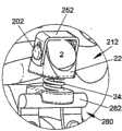
图2A示出根据所公开的另一个示例性实施例的可植入装置的透视图。Figure 2A shows a perspective view of an implantable device according to another disclosed exemplary embodiment.
图2B示出图2A的组装好的装置处于原位的透视图。Figure 2B shows a perspective view of the assembled device of Figure 2A in situ.
图2C示出图2B的被植入装置的放大视图。Figure 2C shows an enlarged view of the implanted device of Figure 2B.
图3A示出根据所公开的又一个示例性实施例的带有基于杆的锚固系统的图2A的组装好的装置处于原位的透视图。3A shows a perspective view of the assembled device of FIG. 2A in situ with a rod-based anchoring system according to yet another disclosed exemplary embodiment.
图3B示出图3A的被植入装置的放大视图。Figure 3B shows an enlarged view of the implanted device of Figure 3A.
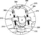
图4示出根据所公开的另一个示例性实施例的可植入装置的透视图。Figure 4 illustrates a perspective view of an implantable device according to another exemplary embodiment disclosed.
图5A示出根据所公开的另一个示例性实施例的带有锁定帽的图4的可植入装置的透视图。5A shows a perspective view of the implantable device of FIG. 4 with a locking cap according to another disclosed exemplary embodiment.
图5B示出图5A的组装好的装置处于原位的透视图。Figure 5B shows a perspective view of the assembled device of Figure 5A in situ.
图5C示出图5B的被植入装置的放大视图。Figure 5C shows an enlarged view of the implanted device of Figure 5B.
图6A示出根据所公开的示例性实施例的带有椎板钩(laminar hook)的图4的可植入装置的部分组装图。6A shows a partially assembled view of the implantable device of FIG. 4 with a laminar hook, according to a disclosed exemplary embodiment.
图6B示出图6A的装置的分解视图。Figure 6B shows an exploded view of the device of Figure 6A.
图7A示出图6A的组装好的装置处于原位的透视图。Figure 7A shows a perspective view of the assembled device of Figure 6A in situ.
图7B示出图7A的被植入装置的放大视图。Figure 7B shows an enlarged view of the implanted device of Figure 7A.
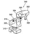
图8A示出根据所公开的另一个示例性实施例的带有椎板钩的图4的可植入装置的透视图。8A shows a perspective view of the implantable device of FIG. 4 with a laminar hook, according to another disclosed exemplary embodiment.
图8B示出图8A的装置的分解视图。Figure 8B shows an exploded view of the device of Figure 8A.
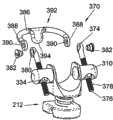
图9A示出根据所公开的另一个示例性实施例的带有椎板钩的图4的可植入装置的透视图。9A shows a perspective view of the implantable device of FIG. 4 with a laminar hook, according to another disclosed exemplary embodiment.
图9B示出图9A的装置的分解视图。Figure 9B shows an exploded view of the device of Figure 9A.
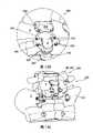
图10A示出图8A的组装好的装置处于原位的后透视图。Figure 1OA shows a rear perspective view of the assembled device of Figure 8A in situ.
图10B示出图10A的被植入装置的放大后视图。Figure 10B shows an enlarged rear view of the implanted device of Figure 10A.
图10C示出图8A的组装好的装置处于原位的前透视图。Figure 10C shows a front perspective view of the assembled device of Figure 8A in situ.
图10D示出图10C的被植入装置的放大前视图。Figure 10D shows an enlarged front view of the implanted device of Figure 10C.
图11A示出图9A的组装好的装置处于原位的透视图。FIG. 11A shows a perspective view of the assembled device of FIG. 9A in situ.
图11B示出图11A的被植入装置的放大视图。FIG. 11B shows an enlarged view of the implanted device of FIG. 11A.
图12A示出根据所公开的又一个示例性实施例的可植入装置的透视图。Figure 12A shows a perspective view of an implantable device according to yet another exemplary embodiment disclosed.
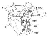
图12B示出图12A的组装好的装置处于原位的透视图。Figure 12B shows a perspective view of the assembled device of Figure 12A in situ.
图12C示出图12B的被植入装置的放大视图。Figure 12C shows an enlarged view of the implanted device of Figure 12B.
图13A示出根据所公开的另一个示例性实施例的可植入装置的透视图。Figure 13A shows a perspective view of an implantable device according to another exemplary embodiment disclosed.
图13B示出图13A的组装好的装置处于原位的透视图。Figure 13B shows a perspective view of the assembled device of Figure 13A in situ.
图13C示出图13B的被植入装置的放大视图。Figure 13C shows an enlarged view of the implanted device of Figure 13B.
图14A示出根据所公开的另一个示例性实施例的可植入装置的透视图。Figure 14A shows a perspective view of an implantable device according to another exemplary embodiment disclosed.
图14B示出图14A的组装好的装置处于原位的透视图。Figure 14B shows a perspective view of the assembled device of Figure 14A in situ.
图14C示出图14B的被植入装置的放大视图。Figure 14C shows an enlarged view of the implanted device of Figure 14B.
具体实施方式Detailed ways
现在详述本发明的示例性实施例,其示例在附图中示出。只要可能,相同的附图标记用于在所有图中表示相同或相似的部件。Exemplary embodiments of the invention will now be described in detail, examples of which are illustrated in the accompanying drawings. Wherever possible, the same reference numbers will be used throughout the drawings to refer to the same or like parts.
本公开提供了这样的可植入装置,所述装置在置于相邻椎骨的棘突之间时用于稳定椎骨,并且所述装置通过置于腰椎骨和相邻椎骨如骶骨之间而用于稳定患者的腰骶区域。如在图1A-1C所示的示例性实施例中所示,可植入装置10可包括构造成植入在腰椎骨4的棘突2如第五腰椎骨(L5)棘突与相邻椎骨之间的间隔体或支承体12。一锚固部件14可设置成将支承体12固定在相邻椎骨上,该相邻椎骨例如可为骶骨8。当植入时,装置10可有助于通过使椎骨4及其棘突2相对于相邻椎骨保持适当的空间位置关系而使脊柱齐整,从而减小椎间盘上的压力。The present disclosure provides implantable devices for stabilizing vertebrae when placed between the spinous processes of adjacent vertebrae and for use by placing between a lumbar vertebra and an adjacent vertebrae such as the sacrum. in the lumbosacral region of the stabilized patient. As shown in the exemplary embodiment shown in FIGS. 1A-1C , the
在一个示例性实施例中,间隔体12可包括构造成安置在棘突2下方的可用作稳定棘突2的台架或支架的第一部件20。第一部件20可包括上表面22、下表面24和在其间延伸的侧壁26。上表面22可包括用于在其上安置棘突2的骨接触区域28。在所示实施例中,骨接触区域28可包括例如限定鞍状区域的成形表面。如所示,骨接触区域28还可包括表面特征如倒钩、表面粗糙化或齿30,以便增强其夹持棘突2的骨表面的能力。表面特征也可包括生物活性涂层,例如包含促进骨组织生长的生物活性材料的多孔涂层。这些表面特征可出现在可植入装置10的任意元件上。In an exemplary embodiment, the
如图1A所示,沿侧壁26可形成沟槽32,并且沟槽32延伸到上表面22上的开口34内。在一个示例性实施例中,可在第一部件20的每个侧面上均形成一个沟槽32。但是,可选地,也可设置延伸穿过第一部件20并在两个侧面上均开口的单个沟槽32。如图1B和1C所示,沟槽32和开口34使得柔性固定元件50如由金属材料、聚合物材料、合成材料或天然材料及其复合物形成的丝线、韧带、条带、织网(fabric webbing)或缝合物能够穿过第一部件20并绕棘突2捆绑,从而将骨头固定在装置10上。As shown in FIG. 1A , a
第一部件20可通过连接部件40附接到第二基底部件60上。第二部件60可包括上表面62、下表面64和在其间延伸的侧壁66。连接部件40可在一端从第一部件20的下表面24延伸至第二基底部件60的上表面62上的第二端。在一个示例性实施例中,连接部件40可为柔性的(即,可压缩和/可伸展的)以便在装置10被植入后为棘突2提供一定限度的运动。在图1A-1C所示的示例性实施例中,连接部件40可具有弹簧42的形式,这使得附接在棘突2上的椎骨4能够以受控的方式弯折、转动和/或侧向弯曲,以便适应患者的活动。The
第二基底部件60可与锚固部件14协作以将可植入装置10固定于患者。如图1B和1C所示,第二基底部件60的下表面64可包括横跨基底部件60延伸的沟槽或凹槽68。锚固部件14可例如具有可拆卸骨板80的形式,骨板80具有构造成保持在基底部件60的凹槽68内的杆状附接端82。在一个示例性实施例中,呈C形的凹槽68使得骨板80可卡扣配合在基底部件60上且仍可转动,从而在支承体12和锚固部件14之间提供了可调节的接头。该柔性为外科医生提供了在植入期间能够根据需要调节骨板80的更大的自由度。此外,支承体12与锚固部件14之间的可调节、可转动的接头使得棘突2能被稳定从而更快地对患者的正常活动作出响应。在杆状附接端82和凹槽68之间可设置例如由聚乙烯如超高分子量聚乙烯(UHMWPE)或聚醚醚酮(PEEK)形成的塑料衬垫,以便提供支承体12相对于板80的平滑滑动。
骨板80还可包括从杆状附接端82伸出的一个或多个延伸部或支脚84。如图1B所示,两个支脚84可从杆状附接端82一端伸出一个。或者在必要时,骨板80可形成有多于两个的支脚84。支脚84还可包括供骨紧固件如骨螺钉88插入的紧固件孔86,从而使得骨板80能够牢固地附接在骨表面如骶骨8上。尽管所述的是螺钉88,但应理解本发明也可使用其它可选的骨紧固件,例如销、大头钉和铆钉。在一个示例性实施例中,支脚84安置成在附接于骶骨上时位于中嵴(median crest)的侧面。也可在支脚84上设置表面特征如生物活性涂层和/或齿30以增强与骨表面的连接。The bone plate 80 may also include one or more extensions or
在植入装置10的一种示例性方法中,可在植入前将间隔体12组装在锚固部件14上。在该方法中,间隔体12可安置成将待支承的椎骨4的棘突2靠在骨接触区域28上,并且锚固部件14顶靠在骶骨8上。随后,可将螺钉88插入穿过紧固件孔86以将锚固部件14紧固定在骶骨8上。可将柔性固定元件50捆绑在棘突2和间隔体12的第一部件20上以将棘突2固定在间隔体12上。In one exemplary method of implanting
或者,可植入被部分组装的装置10。例如,可首先用螺钉88将锚固部件14固定在骶骨8上。接下来,将间隔体12卡扣配合在锚固部件14上并对其进行操作以使待支承的椎骨4的棘突2靠在骨接触区域28上。然后,如图所示,可使用柔性固定元件50将间隔体12的第一部件20固定在棘突上。Alternatively,
图2A-2C示出类似于图1A-1C所示装置10的可植入装置110,但却用柔性垫144将第一部件120连接于第二部件160。装置在所有其它方面中都相同,其中装置110的类似元件与装置10具有相同的附图标记,只是在前面加“1”。柔性垫144可包括弹性体材料。在一个实施例中,柔性垫144可包括包裹弹性体材料如硅树脂或橡胶或可膨胀材料如水凝胶的织物覆盖物。此外,如图2A所示,柔性垫144可形成有摺皱或卷摺以便于压缩和/或弯曲。与弹簧42类似,柔性垫144可使得连接于棘突2的椎骨4能够以受控的方式弯折、转动和/或侧向弯曲以适应患者的活动。可通过选择具有期望的弹性模量的材料形成连接部件40、140或通过改变连接部件40、140的厚度或尺寸以调节阻力水平来控制柔性或阻力的程度。FIGS. 2A-2C show an
如图3A和3B所示,本发明的间隔体12、112也可使用杆和骨锚固系统170固定于患者而非用骨板80、180来连接。使用杆和骨锚固系统170使得本发明的可植入装置10、110能够适于插入脊柱的任何水平(高度)。特别地,基于杆的系统可用于通过将杆的锚固件固定在与被稳定的椎骨及其棘突邻近的椎骨肉茎上而将间隔体12、112固定在任意一对相邻的椎骨之间。As shown in FIGS. 3A and 3B , the
在一个示例性实施例中,杆和骨锚固系统170可包括杆172和至少一个骨锚固件174。骨锚固件174可包括例如多轴螺钉。该装置可构造成使得杆172类似于骨板80的杆状附接端82那样卡入第二基底部件160的沟槽168内。骨锚固件174的适用于本发明的一个示例性实施示出在图3A和3B中。如图所示,骨锚固件174包括伸入头部178内的长形(elongated)螺纹体176。头部178包括用于接纳连接元件如装配在杆172上的球形夹环(未示出)的中空球形腔190。一锁定帽192可由头部178滑动地接纳并且用螺钉194固定在头部178上。锁定帽192也可包括球形腔196以便与球形夹环配合,使得将帽192旋拧在头部178上便可将骨锚固件174固定在杆172上。尽管图3A和3B示出了两个锚固件174,但是根据患者的需要对于任意给定的杆172也可使用多个锚固件174。还应理解,本发明可使用多种不同设计的锚固件,以便为外科医生提供适应解剖学构造差异并以有效的方式将杆172固定于患者的能力。In an exemplary embodiment, rod and
在另一个示例性实施例中,如图4所示,可植入装置210可包括间隔体或支承体212。间隔体212可类似于装置10、110的间隔体12、112,其中装置210的类似元件与装置10具有相同的附图标记,但在前面加“2”。如图所示,间隔体212可包括具有形成翼状突起部236的升高的侧壁226的第一部件220。突起部236形成较深的鞍形区域228,以便在使用时将棘突2安置于其中,并进一步环抱骨头。在突起部236上可设置开口或通孔238以用于附接固定装置。例如,如前述那些用于装置10、110的柔性固定元件50、150也可用于该实施例中以将棘突2固定在支承体212上。In another exemplary embodiment,
或者,也可采用刚性固定元件来提供骨头至可植入装置210的更牢固的连接。图5A-5C示出与锁定帽252一同使用的可植入装置210,锁定帽252具有由一对弯曲支脚256形成的大致为U形的体部。锁定帽252在形状和尺寸上可设定为接合在第一部件220上的支架。位于支脚256上的长形槽258构造成与突起部236的通孔238对准以允许固定元件穿过。在图5A所示的示例性实施例中,在使用时骨紧固件200可插入穿过槽258,将锁定帽252、支承体212和棘突2固定在一起。骨紧固件200可包括伸入到构造成插入穿过骨组织的长形螺纹体204中的头部202。为了将骨紧固件200锁定就位,可设置帽206。如图5A所示,帽206可包括用于接纳螺纹体204的末端的中空体腔208。可在2005年4月8日提交的美国临时申请No.60/669,346中找到适当的骨紧固件200,该专利文件的全部内容引用于此作为参考。Alternatively, rigid fixation elements may also be employed to provide a more secure connection of the bone to the
在其它实施例中,固定元件可包括可与本发明的间隔体或支承体212一同使用的椎板钩300。在图6A所示的示例性实施例中,椎板钩300可包括由曲线形中部304连接的一对支脚302。如图所示,支脚302和中部304共同形成曲线形或波状的M形体部,中部304包括U形突起或凹口。支脚302与位于间隔体212任一侧上的转动臂310协作,以使得钩300可相对于间隔体212作枢转运动。In other embodiments, the fixation element may include a
如图6B所示,转动臂310可具有大致的圆柱形状,具有一个封闭端312和相对的开放端314,开放端314包括大致平行于臂310的纵向轴线延伸的开口316。封闭端312可具有平滑的曲线形边缘,而开放端314可具有平坦的边缘以便能够抵靠间隔体212齐平地安置。为了将各个臂310附接在支承体上,可将锁定帽324插入穿过间隔体212上的一个孔238。锁定帽324可包括头部326和柄部328,以及供销322插入穿过的通孔330。柄部328应当设定尺寸并构造成插入间隔体212的孔238内并且仍然可自由转动。然后,将臂310靠置在柄部328上,且柄部328配合在臂310的开口316中,使得间隔体212夹在它们之间。接下来,可将销322安插在臂310上的通孔320中,其中通孔320构造成与帽324的通孔330对准。因此,所述销使臂310和帽324保持靠在间隔体212上,同时允许臂310和帽324相对于间隔体212自由转动。As shown in FIG. 6B ,
为了将椎板钩300附接在转动臂310上,可将钩300的自由端306插入延伸穿过臂310的开口318,开口318与臂310的纵向轴线大致垂直。钩300的支脚302可包括靠近自由端306的螺纹部308,在组装好时自由端306延伸超出臂310。可设置紧固件334如螺母以将支脚302固定于臂310。如图6A所示,开口318可延伸到加宽的腔336中,该腔允许紧固件334一旦固定在支脚302上就位于其内。尽管示出的是螺纹连接,但可以想到可设置任意适当的替换连接方式来将紧固件334固定至支脚302。例如,支脚302可具有凹口或凹槽,而紧固件334可包括卡合(rachet over)在支脚302上的对应的齿或脊部。在所有情况下,希望提供这样一种将钩300固定在可转动臂310上的机构,其使得外科医生能够灵活地调节钩300相对于间隔体212的长度,以便适应不同患者的解剖学构造。To attach the
一旦完全组装在间隔体212上,则椎板钩300可有助于可植入装置210至椎骨4的定位和连接。如图7A所示,可植入装置210可植入在椎骨4与相邻的椎骨如骶骨8之间。装置210例如可使用前述的骨板80或如所示的杆和螺钉系统170加以连接。此外,应理解装置210可插入到任意相邻的成对椎骨之间。一旦椎骨4的棘突2定位成牢固地靠在间隔体212的鞍形区域228内,则椎板钩300可钩在椎板(组织薄层,lamina)上,其中具有U形突起或凹口的中部304绕椎板延伸。如图7B详示,钩300应当充分地扭转或弯曲以便适应椎板的自然解剖学曲线。Once fully assembled on the
或者,椎板钩300可在可植入装置210已植入到一对椎骨之间后被完全地组装。在这种情况下,可在钩300已绕椎板适当定位后,用紧固件334将支脚302固定在臂310上。此外,如前所述,外科医生可通过操作紧固件334来调节钩300相对于可转动臂310的长度,以便适应患者解剖学构造上的差异。Alternatively,
在本发明的另一个示例性实施例中,提供了一种可包括可枢转头部350的椎板钩340。头部350具有第一端352,如图8A所示,绕椎板抓持的钩或突片(tab)356可从该第一端延伸出来。如图8B所示,头部350的相对的第二端354可包括沿头部350的侧面延伸到开口360的槽358。为了将椎板钩340附接在间隔体212上,可设置具有靠近第一和第二相对端344、346的螺纹部348的支脚342。支脚342的第一端344可插入头部350的槽358内,而支脚342的相对的第二端346可伸入可转动臂310中,其中与前述的用于图6A和6B的椎板钩300的机构类似,支脚342可使用紧固件334固定于臂310。此外,应当理解,在臂310连接于间隔体212的方式上,图8A和8B的椎板钩340可在所有方面都与椎板钩300类似。In another exemplary embodiment of the present invention, a
为了使头部350能够相对于支脚342作枢转运动,可设置圆柱形套管362。套管362可构造成沿头部350的侧面位于圆柱形开口360内,并且尺寸和形状可设定成允许在开口360内自由转动。套管362可包括螺纹孔364以连接于支脚342的第一端344的螺纹部348。尽管示出和描述的是螺纹连接,但可以想到可设置任意适当的替换连接方式来将紧固件334和套管362固定至支脚342。例如,支脚342可具有凹口或凹槽,而紧固件334和套管362可包括相应的齿或脊部以卡合在支脚342上。To enable pivotal movement of the
在组装椎板钩340的一种示例性方法中,可将套管362安置在头部360的开口360内。随后,可将支脚342插入槽358,并且通过将靠近第一端344的螺纹部348旋拧入套管362的螺纹孔364内而将支脚342固定于套管362。然后可将支脚342的自由的第二端346沿间隔体212的侧面插入相连的可转动臂310内,并用紧固件334如螺母将所述第二端固定在可转动臂310中。In one exemplary method of assembling the
与前述的椎板钩300类似,本实施例的完全组装的椎板钩340可有助于可植入装置210至椎骨4的定位和连接。如图10A和10C所示,可植入这种210可植入在椎骨4和相邻椎骨如骶骨8之间。但是,应理解装置210可使用如所示的杆和螺钉系统170插入在任意相邻的成对椎骨之间。如图10B详示,一旦椎骨4的棘突2位于间隔体212的鞍形区域228内,椎板钩340便钩在椎板上,其中钩或突片356绕椎板延伸。通过设置在两个点(即在套管362和臂310处)可枢转的钩340,钩340可适应患者解剖学构造的差异。此外,如图10D详示,支脚340可被扭转或弯曲成更好地顺应椎板的自然解剖学曲线。Similar to the previously described
如前所述,可植入装置210可在椎板钩340完全附接在间隔体212上的情况下被植入。或者,椎板钩340可在可植入装置210已插入到一对椎骨之间后完全地附接到间隔体212上。在这种情况下,椎板钩340可在可植入装置210(包括可转动臂310)植入时被部分组装(即支脚342连接于头部350)。随后,一旦钩340已绕椎板适当定位,便可用紧固件334将支脚342固定于臂310。当然,如前所述,外科医生可通过相对于可转动臂310和支脚342操作紧固件334来调节钩340的长度,以便适应患者解剖学构造的差异。As previously described,
现在转到图9A和9B,示出了椎板钩370的又一个示例性实施例。如图9A所示,钩370可包括一对支脚372和通过铰接接头384可枢转地连接于支脚372的桥接部386。每个支脚372可包括具有螺钉开口380的第一端374和包括插入到可转动臂310中的螺纹部378的第二相对端376,其中与前述的用于椎板钩300、340的机构类似,支脚372可使用紧固件334固定于臂310。在臂310连接于间隔体212的方式上,图9A和9B的椎板钩370在所有方面都可与椎板钩300、340类似。Turning now to FIGS. 9A and 9B , yet another exemplary embodiment of a
如图9A和9B所示,桥接部386可具有大致为U形的形状,带有在螺钉开口390处终止的自由端388。如图9A所示,桥接部386的中部392可包括以一角度从其延伸的突片394。突片394可具有适于绕椎板夹持或抓持的任意形状和尺寸,例如所示的实心板。但是,可以想到突片394也可为U形体。此外,突片394可与桥接部386一体形成或作为分离的部件形成。如果需要,突片394可构造成在植入期间可调节角度并相对于桥接部386固定在期望的角度以便具有更大的灵活性。As shown in FIGS. 9A and 9B , the
在组装椎板钩370的一种示例性方法中,可通过将紧固件382如螺钉插入穿过支脚的开口380和桥接部386的开口390而将桥接部386附接于支脚372。随后,可将支脚372沿间隔体212的侧面插入到相连的可转动臂310中,并用紧固件334如螺母将支脚固定在可转动臂内。In one exemplary method of assembling the
与前述的椎板钩300、340一样,本实施例的完全组装的椎板钩370可有助于可植入装置210至椎骨4的定位和连接。如图11A和11B所示,可植入装置210可植入在椎骨4和相邻椎骨如骶骨8之间。当然,应理解装置210可使用如图所示的杆和螺钉系统170插入到任意相邻的成对椎骨之间。如图11B详示,一旦椎骨4的棘突2位于间隔体212的鞍形区域228内,椎板钩370便可钩在椎板上,而突片394绕椎板延伸。通过设置在两个点(即在铰接接头384和可转动臂310处)可枢转的钩370,钩370可适应患者解剖学构造的差异。此外,应理解,与椎板钩340的支脚342类似,支脚372可被扭转或弯曲成更好地顺应椎板的自然解剖学曲线。As with the previously described
如在上述方法中所述,可植入装置210可在椎板钩370完全附接在间隔体212上的情况下被植入。或者,椎板钩370可在可植入装置210已插入到一对椎骨之间后完全地附接到间隔体212上。在这种情况下,椎板钩370可在可植入装置210(包括可转动臂310)植入时被部分组装(即支脚372连接于桥接部386)。随后,一旦突片394已绕椎板适当定位,便可用紧固件334将支脚372固定于臂310。如前所述,外科医生可通过相对于可转动臂310和支脚372操作紧固件334来调节钩370的高度,以便适应患者解剖学构造的差异。
本发明的椎板钩300、340、370可由各种适当的生物相容性材料单独地或相互组合地形成。用于形成钩300、340、370的全部或部分的适当材料包括金属如不锈钢、钛及其合金,以及聚合物如聚醚醚酮(PEEK)。当然,应理解也可使用其它适当的材料而不会背离本发明的精神。The laminar hooks 300, 340, 370 of the present invention may be formed from various suitable biocompatible materials alone or in combination with each other. Suitable materials for forming all or part of the
如果需要,也可设置比前述的用于棘突2的稳定支承的装置需要更少组装的整体式的固定体,例如由本公开提供的支承体或支架412、512、612。如图12A-12C所示,根据本公开一个示例性实施例的可植入装置410包括与可植入装置10具有相似特征的支架412。在适当之处,装置410的类似元件用与装置10相同的附图标记在前面加“4”表示。支架412可包括构造成安置在棘突2下方的骨台架部420。台架部420可延伸到颈部区域416,后者可延伸到锚固部,该锚固部构造为例如用于附接至相邻椎骨的骨板480。如所示,台架部420可相对于骨板480以约90度角延伸。但是,应理解,台架部420可相对于锚固部以各种角度延伸而不背离本发明的精神。If desired, a one-piece fixation body that requires less assembly than the aforementioned means for stable support of the
与支承体12一样,台架部420可包括上表面422、下表面424和在其间延伸的侧壁426。上表面422可包括限定用于在其上安置棘突2的鞍形区域428的成形区域。如图12A所示,沟槽432可沿侧壁426形成并延伸到上表面422上的开口434内。在一个示例性实施例中,在台架部420的每个侧面上均可形成一个沟槽432。但是,可选地,也可设置延伸穿过台架部420并在两个侧面上均开口的单个沟槽432。如图12B和12C所示,柔性固定元件450如由金属材料、聚合物材料、合成材料或天然材料及其复合物形成的丝线、韧带、条带、织网或缝合物可穿过台架部420并绕棘突2捆绑,从而将骨头固定在装置410上。Like the
台架部420可延伸到可包括一个或多个延伸部或支脚484的骨板480。如图12B所示,可设置两个支脚484。当然,如果需要,骨板480可形成有多于两个的支脚484。支脚484还可包括供紧固件如骨螺钉488插入的紧固件孔486,从而使得骨板480能够牢固地附接在骨表面如骶骨8上。在一个示例性实施例中,支脚484安置成在骨板480附接于骶骨8上时位于中嵴的侧面。也可在支脚484上设置表面特征如生物活性涂层和/或齿430以增强与骨表面的连接。The
在图13A-13C所示的另一个示例性实施例中,示出了包括整体式的支承体或支架512的可植入装置510。可植入装置510与可植入装置10具有相似的特征。在适当之处,装置510的类似元件用与装置10相同的附图标记表示,但在前面加“5”。支架512包括延伸到骨板580的骨载持部520。与图4和图5A-5C的支承体212一样,骨载持部520可包括形成翼状突起部536的升高的侧壁526。突起部536形成较深的鞍形区域528,以便在使用时将棘突2安置于其中,并进一步环抱或支承骨头。在突起部536上可设置开口或通孔538以用于附接固定装置。例如,如前述那些用于装置10、110的柔性固定元件也可用于该实施例中以将棘突2固定在载持部520上。或者,也可使用那些与可植入装置210所设有的相类似的刚性固定元件如锁定帽和骨紧固件(未示出),以便将骨头牢固地固定于支架512。此外,也可和本实施例的支架512一同使用与前述类似的椎板钩300、340、370。In another exemplary embodiment shown in FIGS. 13A-13C , an implantable device 510 including an integral support or stent 512 is shown. Implantable device 510 has similar features to
与支架412类似,载持部520可延伸到锚固部,该锚固部例如被构造为可包括一个或多个延伸部或支脚584的骨板580。如图13B所示,可设置两个支脚584。当然,如果需要,骨板580可形成有多于两个的支脚584。支脚584还可包括供紧固件如骨螺钉588插入的紧固件孔586,从而使得骨板580能够牢固地附接在骨表面如骶骨8上。在一个示例性实施例中,支脚584安置成在骨板580附接于骶骨上时位于中嵴的侧面。也可在支脚584上设置表面特征如生物活性涂层和/或齿530以增强与骨表面的连接。Similar to bracket 412 , carrier portion 520 may extend to an anchor portion configured, for example, as bone plate 580 that may include one or more extensions or feet 584 . As shown in Figure 13B, two legs 584 may be provided. Of course, the bone plate 580 may be formed with more than two feet 584, if desired. The feet 584 may also include fastener holes 586 for insertion of fasteners, such as bone screws 588 , thereby enabling the bone plate 580 to be securely attached to a bony surface, such as the
图14A-14C示出本公开的又一个示例性实施例。如所示,可植入装置610包括整体式的支架612,支架612包括在一端具有台架部620并在相对端具有锚固部680的体部616。可植入装置610与可植入装置10具有相似的特征。在适当之处,装置610的类似元件用与装置10相同的附图标记在前面加“6”表示。台架部620能以与图12A-12C所示的可植入装置410的台架部420类似的方式构造而成以便支承棘突2。但是,在所示实施例中,台架部620延伸到终止于锚固部680的体部616。锚固部680可包括一对在其间限定夹骨部648的支脚684。在使用时,支架612可安置成使得棘突2靠在台架部620的鞍形区域628上并且柔性固定元件650将骨头固定于台架部620。锚固部680可安置成抵靠相邻椎骨的骨表面如中嵴,其中相邻椎骨为骶骨8。但是,应理解可改变可植入装置610的尺寸(即高度和宽度)和形状以用在脊柱的任意水平处。14A-14C illustrate yet another exemplary embodiment of the present disclosure. As shown,
本公开的支承体或支架412、512、612可根据为其构造所选择的材料和患者的特定需要而被设置成刚性的固定装置或半刚性的、柔性的固定装置。也就是说,可通过由生物相容性金属如钛或不锈钢、或刚性聚合物如聚醚醚酮(PEEK)构造所述支架来提供刚性的固定装置。但是,也可通过由聚合体材料如硅树脂、橡胶类材料或聚乙烯如超高分子量聚乙烯(UHMWPE)构造所述支架来提供具有一定限度的柔性(即压缩和/或伸展)的半刚性固定装置。此外,可以想到,所述装置可由所述材料的组合构造而成以提供半柔性、半刚性的固定装置。例如,支架412、512的大部分可由金属制造,只有颈部区域416、516包括聚合体材料,使得在正常压缩载荷下可实现一些压缩和/伸展。The supports or braces 412, 512, 612 of the present disclosure may be provided as rigid fixation devices or as semi-rigid, flexible fixation devices depending on the materials chosen for their construction and the specific needs of the patient. That is, a rigid fixation device can be provided by constructing the stent from a biocompatible metal such as titanium or stainless steel, or a rigid polymer such as polyetheretherketone (PEEK). However, it is also possible to provide a semi-rigid structure with limited flexibility (i.e. compression and/or extension) by constructing the scaffold from a polymeric material such as silicone, a rubber-like material, or a polyethylene such as ultra-high molecular weight polyethylene (UHMWPE). Fixtures. Furthermore, it is contemplated that the device may be constructed from a combination of the materials described to provide a semi-flexible, semi-rigid fixation device. For example, the majority of the brace 412, 512 may be fabricated from metal, with only the
通常,可基于期望程度的柔性和/或可压缩性或为了提供生物相容性和/或生物活性特征来选择可植入装置的各个部分所包含的特定材料。多种生物相容性材料都适于形成本公开的装置。例如,在一个实施例中,装置可由医用等级金属如纯钛或钛合金如钛-钒-铝合金形成。装置也可由例如不锈钢或钴铬合金形成。装置还可由形状记忆材料如镍钛或镍钛诺形成。其它适当的生物相容性材料包括陶瓷材料。陶瓷材料可为颗粒混合物,如一种金属或多种金属和/或一种陶瓷非金属材料或多种陶瓷非金属材料的混合物。In general, the particular materials that various portions of the implantable device comprise can be selected based on a desired degree of flexibility and/or compressibility or to provide biocompatibility and/or bioactivity characteristics. A variety of biocompatible materials are suitable for forming the devices of the present disclosure. For example, in one embodiment, the device may be formed from a medical grade metal such as pure titanium or a titanium alloy such as titanium-vanadium-aluminum alloy. The device may also be formed from, for example, stainless steel or cobalt chrome. Devices can also be formed from shape memory materials such as nickel titanium or nitinol. Other suitable biocompatible materials include ceramic materials. The ceramic material may be a mixture of particles, such as a metal or metals and/or a ceramic non-metal material or a mixture of ceramic non-metal materials.
本发明的可植入装置也可由适当的生物相容性聚合物材料形成。适当的合成聚合物的示例包括但不限于聚乙烯醇(PVA)及其烷化或酰化衍生物、聚乙烯(PE)、聚亚安酯(PU)、聚丙烯(PP)、尼龙、聚己酸内酯(PCL),以及它们的共聚物及组合。适当的合成非生物可降解聚合物的示例包括但不限于各种聚丙烯酸酯、乙烯-醋酸乙烯酯(及其它替换酰基的醋酸纤维素)、聚苯乙烯、聚乙烯氧化物、聚乙烯氟化物、聚(乙烯基咪唑)、氯磺酸聚烯烃、聚环氧乙烷、聚四氟乙烯和尼龙。另一种特别适用于生产可模塑成分的聚合物材料为乙烯基酯的水解聚合物或共聚物,特别是醋酸乙烯酯的水解聚合物或共聚物。其它优选的聚合材料包括超高分子量聚乙烯(UHMWPE)和聚醚醚酮(PEEK)。The implantable devices of the present invention may also be formed from suitable biocompatible polymeric materials. Examples of suitable synthetic polymers include, but are not limited to, polyvinyl alcohol (PVA) and its alkylated or acylated derivatives, polyethylene (PE), polyurethane (PU), polypropylene (PP), nylon, polyethylene Caprolactone (PCL), and their copolymers and combinations. Examples of suitable synthetic non-biodegradable polymers include, but are not limited to, various polyacrylates, ethylene vinyl acetate (and other acyl-substituted cellulose acetates), polystyrene, polyethylene oxide, polyethylene fluoride , poly(vinylimidazole), polyolefin chlorosulfonate, polyethylene oxide, polytetrafluoroethylene, and nylon. Another polymeric material particularly suitable for use in the production of moldable components is a hydrolyzed polymer or copolymer of vinyl esters, especially hydrolyzed polymers or copolymers of vinyl acetate. Other preferred polymeric materials include ultra high molecular weight polyethylene (UHMWPE) and polyetheretherketone (PEEK).
本发明装置的柔性部分特别如柔性连接部件40或可压缩垫140可由适当的弹性体材料如硅树脂和天然或合成橡胶或橡胶类材料形成。或者,柔性连接部件40可由前述的任意生物相容性金属形成。特别对于垫140,可用包含在例如由织物形成的保持罩盖或护套内的弹性或粘弹性材料来制造垫140。The flexible parts of the device of the invention, in particular the flexible connecting
多种纤维材料都适用于形成织物覆盖物,例如聚酯、聚乙烯和其它高韧性的聚合织物以及碳纤维纱线、陶瓷纤维、金属纤维,包括这些材料中的一种或多种的混合物并且包括由其制成的纤维。可使用编织、针织、编结或刺绣来制造织物。织物可形成为期望的外形或从较大量的织物例如通过切割或加压而减小至期望的外形。A variety of fibrous materials are suitable for use in forming the fabric covering, such as polyester, polyethylene and other high tenacity polymeric fabrics as well as carbon fiber yarns, ceramic fibers, metal fibers, including mixtures of one or more of these materials and including fibers made from it. Fabrics can be made using weaving, knitting, braiding or embroidery. The fabric may be formed to a desired shape or reduced to a desired shape from a larger mass of fabric, for example by cutting or pressing.
织物覆盖物内的弹性或粘弹性芯材可包括前述任意适当材料。芯部也可包括可膨胀塑料如聚合合成物或水凝胶,如聚乙烯醇、聚烯吡酮或聚丙烯酸或聚甲基丙烯酸的衍生物。适当的聚合物的示例为聚亚安酯、聚脲、PAN、聚二甲基硅氧烷(硅橡胶)和高度结晶的多嵌段丙烯酸和甲基丙烯酸共聚物。适当的亲水聚合物的示例为高分子量聚丙烯酰胺、聚丙烯酸、聚烯吡酮、聚环氧乙烷、环氧乙烷和环氧丙烷或透明质酸的共聚物;共价交联水凝胶如亲水酯或聚丙烯酸或聚甲基丙烯酸的氨基化合物;物理交联的水凝胶如PAN的水解物或氨解物。The elastic or viscoelastic core within the fabric cover may comprise any suitable material as described above. The core may also comprise expandable plastics such as polymeric composites or hydrogels, such as polyvinyl alcohol, povidone or derivatives of polyacrylic acid or polymethacrylic acid. Examples of suitable polymers are polyurethane, polyurea, PAN, polydimethylsiloxane (silicone rubber) and highly crystalline multi-block acrylic and methacrylic copolymers. Examples of suitable hydrophilic polymers are high molecular weight polyacrylamide, polyacrylic acid, povidone, polyethylene oxide, copolymers of ethylene oxide and propylene oxide or hyaluronic acid; covalently crosslinked water Gels such as hydrophilic esters or amino compounds of polyacrylic acid or polymethacrylic acid; physically cross-linked hydrogels such as hydrolyzate or ammonolyzate of PAN.
用于形成柔性垫140的弹性体材料的水凝胶包括轻微交联的生物相容性同聚物,和亲水单体如2-羟烷基丙烯酸酯和甲基丙烯酸脂的共聚物,如2-羟乙基丙烯酸脂(HEMA);N-乙烯基单体如N-乙烯基-2-吡咯烷酮(N-VP);不饱和乙烯酸如甲基丙烯酸(MA)和不饱和乙烯基如2-(二乙基氨基)甲基丙烯酸乙酯(DEAEMA)。共聚物还可包括来自非亲水单体如甲基丙烯酸烷基酯例如甲基丙烯酸甲酯(MMA)等等的残余物。另一种类型的适当水凝胶包括HYPANTM和聚(乙烯醇)(PVA)水凝胶。The hydrogels used to form the elastomeric material of the
为了进一步提高装置在植入后附接于周围骨骼的能力,装置可包括多种表面改型(surface modification)。例如,可植入装置的各部分可包括有利于组织连接、结合或固定的表面变动。这些变动可包括表面齿、倒钩、凸缘、表面粗糙化或向装置的一个或多个部分添加生物活性涂层。此外,装置还可包括粗糙的或多孔的表面。粗糙的或多孔的表面可增强植入物表面与骨组织之间的连接。此外,某些多孔表面可促进组织向内生长以在装置的各部分与周围的骨骼和/或软组织之间形成生物结合。粗糙的或多孔的表面可包括在装置的任意部分上,并且特别希望位于装置的与骨组织直接接触的部分如支承体12的上表面22或支承体212的鞍形区域228,这可利于骨组织向内生长。To further enhance the ability of the device to attach to the surrounding bone after implantation, the device may include various surface modifications. For example, portions of the implantable device may include surface alterations that facilitate tissue attachment, bonding, or fixation. These alterations may include surface teeth, barbs, flanges, surface roughening, or adding a bioactive coating to one or more portions of the device. In addition, devices may also include rough or porous surfaces. Rough or porous surfaces enhance the connection between the implant surface and bone tissue. Additionally, certain porous surfaces may promote tissue ingrowth to form a biobond between portions of the device and surrounding bone and/or soft tissue. Rough or porous surfaces can be included on any part of the device, and are particularly desirable to be located on parts of the device that are in direct contact with bone tissue, such as the
装置的表面也可包括生物活性剂。这些活性剂可包括成骨因子以进一步促进装置的部件与周围的骨骼和/或软组织之间的结合。此外,装置可包括治疗剂,例如抗生素、类固醇、抗血栓剂、消炎药和/或止痛剂。在一个实施例中,生物活性剂可包含在装置上的涂层内。作为替换地或附加地,装置可为多孔的并且生物活性剂可包含在装置的孔内。生物活性剂可例如为用于促使软骨或骨骼生长的骨形成蛋白/骨形态发生蛋白(BMP)。The surface of the device may also include bioactive agents. These active agents may include osteogenic factors to further promote bonding between components of the device and surrounding bone and/or soft tissue. Additionally, the device may include therapeutic agents such as antibiotics, steroids, antithrombotics, anti-inflammatory drugs, and/or pain relievers. In one embodiment, the bioactive agent may be included in a coating on the device. Alternatively or additionally, the device may be porous and the bioactive agent may be contained within the pores of the device. The bioactive agent may eg be bone morphogenic protein/bone morphogenetic protein (BMP) for promoting cartilage or bone growth.
可以想到,外科医生可使用本公开的装置来治疗多种临床问题。例如,所述装置可用于治疗椎间盘退变性疾病和/或椎间盘突出。所述装置也可用于治疗椎管狭窄,包括中央管和/或侧方管狭窄。所述装置可在其它治疗或植入——包括邻近的刚性固定、邻近的脊椎减压、融合和/或关节面置换(facet replacement)或修复——之前、之后或与它们结合使用。It is contemplated that surgeons may use the devices of the present disclosure to treat a variety of clinical problems. For example, the device may be used to treat degenerative disc disease and/or a herniated disc. The device may also be used to treat spinal stenosis, including central and/or lateral canal stenosis. The device may be used before, after, or in conjunction with other treatments or implants, including adjacent rigid fixation, adjacent spinal decompression, fusion, and/or facet replacement or repair.
本公开的装置能以多种方式被手术植入而不损害装置的效能。例如,外科医生可选择多种不同的手术方法和/或切口位置和/或大小。此外,外科医生可按不同顺序植入装置的各个部件。可根据特定于患者的临床因素选择特定的手术过程。The devices of the present disclosure can be surgically implanted in a variety of ways without compromising the efficacy of the device. For example, the surgeon may choose from a number of different surgical methods and/or incision locations and/or sizes. Furthermore, the surgeon may implant the various components of the device in a different order. A particular surgical procedure can be selected based on patient-specific clinical factors.
可使用多种不同的切口和/或手术过程来植入本公开的装置。例如,在一个实施例中,外科医生可使用在腰椎和骶椎上方的中线切口以暴露出L5-S1棘突间区域。或者,外科医生可使用位于脊柱侧面的一个或多个切口。此外,外科医生可使用侵入性最小的手段——包括各种不同的观测仪器、套管和/或机器人式(智能型)植入装置——以将所述装置送至手术部位。A variety of different incisions and/or surgical procedures may be used to implant the devices of the present disclosure. For example, in one embodiment, the surgeon may use a midline incision over the lumbar and sacral vertebrae to expose the L5-S1 interspinous region. Alternatively, the surgeon may use one or more incisions on the side of the spine. In addition, the surgeon may use minimally invasive means, including various scopes, cannulas, and/or robotic (smart) implants, to deliver the device to the surgical site.
可以想到,本公开的装置10可提供用于治疗各种脊柱疾病的改进的系统和方法。例如,所述装置提供了用于治疗在L5-S1脊椎水平/高度的脊柱疾病的机构。此外,本公开的装置还可用于治疗位于其它脊椎水平的脊柱疾病。但是,本发明的装置也可用于稳定L5水平之上的腰椎骨。例如,对于L5椎板切除术,在将基于杆的装置系统的螺钉安置在相邻的L5椎骨的肉茎内时,可使用本发明的装置来稳定L4椎骨,从而在L4-L5区域之间提供支承桥。因此,可以想到,本公开所提供的装置、特别是基于杆的系统可用于通过将杆的锚固件固定于相邻椎骨的肉茎而将任何一对相邻椎骨稳定在被支承的棘突上。It is contemplated that the
本公开的方法和装置与包括脊柱融合术和全椎间盘置换术在内的其它方法相比具有显著较低的侵入性,和/或产生更不明显和更加可逆的解剖学构造变化。本公开的装置可限制正常的脊柱运动但在弯曲、伸展、转动和/或侧弯方面提供了一定的受控运动。此外,本公开的装置和方法可尤其适用于治疗椎间盘退变性疾病和/或脊椎狭窄的不同阶段,特别是在L5-S1水平。The methods and devices of the present disclosure are significantly less invasive and/or produce less pronounced and more reversible anatomical changes than other procedures, including spinal fusion and total disc replacement. The devices of the present disclosure can restrict normal spinal motion but provide some controlled motion in flexion, extension, rotation, and/or lateral bending. Furthermore, the devices and methods of the present disclosure may be particularly useful for treating different stages of degenerative disc disease and/or spinal stenosis, particularly at the L5-S1 level.
考虑到本说明书和本文所公开的本发明的实践,本发明的其它实施例对于本领域技术人员而言是显而易见的。本说明书和示例应被看作仅仅是示例性的,本发明的真正范围和精神由所附权利要求来限定。Other embodiments of the invention will be apparent to those skilled in the art from consideration of the specification and practice of the invention disclosed herein. The specification and examples should be considered exemplary only, with the true scope and spirit of the invention defined by the appended claims.
Claims (65)
Translated fromChinesePriority Applications (1)
| Application Number | Priority Date | Filing Date | Title |
|---|---|---|---|
| CN201310054315.XACN103169533B (en) | 2005-09-27 | 2006-09-26 | Interspinous vertebral stabilization devices |
Applications Claiming Priority (3)
| Application Number | Priority Date | Filing Date | Title |
|---|---|---|---|
| US72080905P | 2005-09-27 | 2005-09-27 | |
| US60/720,809 | 2005-09-27 | ||
| PCT/US2006/037401WO2007038475A2 (en) | 2005-09-27 | 2006-09-26 | Interspinous vertebral stabilization devices |
Related Child Applications (1)
| Application Number | Title | Priority Date | Filing Date |
|---|---|---|---|
| CN201310054315.XADivisionCN103169533B (en) | 2005-09-27 | 2006-09-26 | Interspinous vertebral stabilization devices |
Publications (2)
| Publication Number | Publication Date |
|---|---|
| CN101316558Atrue CN101316558A (en) | 2008-12-03 |
| CN101316558B CN101316558B (en) | 2013-03-27 |
Family
ID=37668164
Family Applications (2)
| Application Number | Title | Priority Date | Filing Date |
|---|---|---|---|
| CN201310054315.XAExpired - Fee RelatedCN103169533B (en) | 2005-09-27 | 2006-09-26 | Interspinous vertebral stabilization devices |
| CN2006800441722AExpired - Fee RelatedCN101316558B (en) | 2005-09-27 | 2006-09-26 | Interspinous spine stabilization device |
Family Applications Before (1)
| Application Number | Title | Priority Date | Filing Date |
|---|---|---|---|
| CN201310054315.XAExpired - Fee RelatedCN103169533B (en) | 2005-09-27 | 2006-09-26 | Interspinous vertebral stabilization devices |
Country Status (14)
| Country | Link |
|---|---|
| US (3) | US8328848B2 (en) |
| EP (2) | EP1942817B1 (en) |
| JP (1) | JP5047176B2 (en) |
| KR (1) | KR101332384B1 (en) |
| CN (2) | CN103169533B (en) |
| AR (1) | AR057832A1 (en) |
| AU (1) | AU2006294772B2 (en) |
| CA (1) | CA2623883C (en) |
| ES (2) | ES2465568T3 (en) |
| IL (1) | IL190417A0 (en) |
| MX (1) | MX344497B (en) |
| TW (1) | TWI423782B (en) |
| WO (1) | WO2007038475A2 (en) |
| ZA (1) | ZA200802860B (en) |
Cited By (4)
| Publication number | Priority date | Publication date | Assignee | Title |
|---|---|---|---|---|
| CN103083116A (en)* | 2013-01-31 | 2013-05-08 | 姚豹 | Thoracolumbar spine semi-vertebral plate restorer |
| WO2014012491A1 (en)* | 2012-07-17 | 2014-01-23 | 上海微创骨科医疗科技有限公司 | Dynamic and steady spinal column implant unit |
| CN104546228A (en)* | 2015-01-07 | 2015-04-29 | 北京爱康宜诚医疗器材股份有限公司 | Adjustable self-stabilizing type artificial sacrum prosthesis |
| CN107072797A (en)* | 2014-10-20 | 2017-08-18 | 索尔科生物医疗株式会社 | Dynamic implantation body between spinous process |
Families Citing this family (141)
| Publication number | Priority date | Publication date | Assignee | Title |
|---|---|---|---|---|
| FR2812185B1 (en) | 2000-07-25 | 2003-02-28 | Spine Next Sa | SEMI-RIGID CONNECTION PIECE FOR RACHIS STABILIZATION |
| GB0107708D0 (en) | 2001-03-28 | 2001-05-16 | Imp College Innovations Ltd | Bone fixated,articulated joint load control device |
| US8114158B2 (en) | 2004-08-03 | 2012-02-14 | Kspine, Inc. | Facet device and method |
| US9161783B2 (en) | 2004-10-20 | 2015-10-20 | Vertiflex, Inc. | Interspinous spacer |
| US8425559B2 (en) | 2004-10-20 | 2013-04-23 | Vertiflex, Inc. | Systems and methods for posterior dynamic stabilization of the spine |
| US9119680B2 (en) | 2004-10-20 | 2015-09-01 | Vertiflex, Inc. | Interspinous spacer |
| US8945183B2 (en) | 2004-10-20 | 2015-02-03 | Vertiflex, Inc. | Interspinous process spacer instrument system with deployment indicator |
| US8273108B2 (en) | 2004-10-20 | 2012-09-25 | Vertiflex, Inc. | Interspinous spacer |
| US8128662B2 (en) | 2004-10-20 | 2012-03-06 | Vertiflex, Inc. | Minimally invasive tooling for delivery of interspinous spacer |
| US8123807B2 (en) | 2004-10-20 | 2012-02-28 | Vertiflex, Inc. | Systems and methods for posterior dynamic stabilization of the spine |
| US9023084B2 (en) | 2004-10-20 | 2015-05-05 | The Board Of Trustees Of The Leland Stanford Junior University | Systems and methods for stabilizing the motion or adjusting the position of the spine |
| US7763074B2 (en) | 2004-10-20 | 2010-07-27 | The Board Of Trustees Of The Leland Stanford Junior University | Systems and methods for posterior dynamic stabilization of the spine |
| US8152837B2 (en) | 2004-10-20 | 2012-04-10 | The Board Of Trustees Of The Leland Stanford Junior University | Systems and methods for posterior dynamic stabilization of the spine |
| US8409282B2 (en) | 2004-10-20 | 2013-04-02 | Vertiflex, Inc. | Systems and methods for posterior dynamic stabilization of the spine |
| US8012207B2 (en) | 2004-10-20 | 2011-09-06 | Vertiflex, Inc. | Systems and methods for posterior dynamic stabilization of the spine |
| US8317864B2 (en) | 2004-10-20 | 2012-11-27 | The Board Of Trustees Of The Leland Stanford Junior University | Systems and methods for posterior dynamic stabilization of the spine |
| US8277488B2 (en) | 2004-10-20 | 2012-10-02 | Vertiflex, Inc. | Interspinous spacer |
| US8613747B2 (en) | 2004-10-20 | 2013-12-24 | Vertiflex, Inc. | Spacer insertion instrument |
| US8123782B2 (en) | 2004-10-20 | 2012-02-28 | Vertiflex, Inc. | Interspinous spacer |
| US8167944B2 (en) | 2004-10-20 | 2012-05-01 | The Board Of Trustees Of The Leland Stanford Junior University | Systems and methods for posterior dynamic stabilization of the spine |
| US8241330B2 (en) | 2007-01-11 | 2012-08-14 | Lanx, Inc. | Spinous process implants and associated methods |
| US9055981B2 (en) | 2004-10-25 | 2015-06-16 | Lanx, Inc. | Spinal implants and methods |
| WO2006058221A2 (en) | 2004-11-24 | 2006-06-01 | Abdou Samy M | Devices and methods for inter-vertebral orthopedic device placement |
| EP2219538B1 (en) | 2004-12-06 | 2022-07-06 | Vertiflex, Inc. | Spacer insertion instrument |
| US8845726B2 (en) | 2006-10-18 | 2014-09-30 | Vertiflex, Inc. | Dilator |
| US7850732B2 (en)* | 2006-12-11 | 2010-12-14 | Warsaw Orthopedic, Inc. | Sacral prosthesis and surgical method |
| US9247968B2 (en) | 2007-01-11 | 2016-02-02 | Lanx, Inc. | Spinous process implants and associated methods |
| US9265532B2 (en) | 2007-01-11 | 2016-02-23 | Lanx, Inc. | Interspinous implants and methods |
| US7842074B2 (en) | 2007-02-26 | 2010-11-30 | Abdou M Samy | Spinal stabilization systems and methods of use |
| AU2008241447B2 (en) | 2007-04-16 | 2014-03-27 | Vertiflex, Inc. | Interspinous spacer |
| US20080269897A1 (en)* | 2007-04-26 | 2008-10-30 | Abhijeet Joshi | Implantable device and methods for repairing articulating joints for using the same |
| US20080268056A1 (en)* | 2007-04-26 | 2008-10-30 | Abhijeet Joshi | Injectable copolymer hydrogel useful for repairing vertebral compression fractures |
| US8409281B2 (en)* | 2007-05-01 | 2013-04-02 | Moximed, Inc. | Adjustable absorber designs for implantable device |
| US8123805B2 (en) | 2007-05-01 | 2012-02-28 | Moximed, Inc. | Adjustable absorber designs for implantable device |
| US8709090B2 (en) | 2007-05-01 | 2014-04-29 | Moximed, Inc. | Adjustable absorber designs for implantable device |
| US8894714B2 (en) | 2007-05-01 | 2014-11-25 | Moximed, Inc. | Unlinked implantable knee unloading device |
| US10022154B2 (en)* | 2007-05-01 | 2018-07-17 | Moximed, Inc. | Femoral and tibial base components |
| US7655041B2 (en)* | 2007-05-01 | 2010-02-02 | Moximed, Inc. | Extra-articular implantable mechanical energy absorbing systems and implantation method |
| US20100137996A1 (en)* | 2007-05-01 | 2010-06-03 | Moximed, Inc. | Femoral and tibial base components |
| US9907645B2 (en) | 2007-05-01 | 2018-03-06 | Moximed, Inc. | Adjustable absorber designs for implantable device |
| US20110245928A1 (en) | 2010-04-06 | 2011-10-06 | Moximed, Inc. | Femoral and Tibial Bases |
| US20080275567A1 (en)* | 2007-05-01 | 2008-11-06 | Exploramed Nc4, Inc. | Extra-Articular Implantable Mechanical Energy Absorbing Systems |
| US9381047B2 (en) | 2007-05-09 | 2016-07-05 | Ebi, Llc | Interspinous implant |
| US9173686B2 (en)* | 2007-05-09 | 2015-11-03 | Ebi, Llc | Interspinous implant |
| EP1994900A1 (en)* | 2007-05-22 | 2008-11-26 | Flexismed SA | Interspinous vertebral implant |
| US8070779B2 (en)* | 2007-06-04 | 2011-12-06 | K2M, Inc. | Percutaneous interspinous process device and method |
| US8202300B2 (en)* | 2007-12-10 | 2012-06-19 | Custom Spine, Inc. | Spinal flexion and extension motion damper |
| AU2009206098B2 (en) | 2008-01-15 | 2014-10-30 | Vertiflex, Inc. | Interspinous spacer |
| US20090248077A1 (en)* | 2008-03-31 | 2009-10-01 | Derrick William Johns | Hybrid dynamic stabilization |
| US20090248078A1 (en)* | 2008-04-01 | 2009-10-01 | Zimmer Spine, Inc. | Spinal stabilization device |
| US9168065B2 (en)* | 2008-04-30 | 2015-10-27 | Moximed, Inc. | Ball and socket assembly |
| US20090297603A1 (en)* | 2008-05-29 | 2009-12-03 | Abhijeet Joshi | Interspinous dynamic stabilization system with anisotropic hydrogels |
| US20100121381A1 (en)* | 2008-06-09 | 2010-05-13 | Springback, Inc. | Surgical method and apparatus for treating spinal stenosis and stabilization of vertebrae |
| US8828058B2 (en) | 2008-11-11 | 2014-09-09 | Kspine, Inc. | Growth directed vertebral fixation system with distractible connector(s) and apical control |
| WO2010088621A1 (en)* | 2009-02-02 | 2010-08-05 | Simpirica Spine, Inc. | Sacral tether anchor and methods of use |
| US20110137345A1 (en)* | 2009-03-18 | 2011-06-09 | Caleb Stoll | Posterior lumbar fusion |
| US8372117B2 (en) | 2009-06-05 | 2013-02-12 | Kyphon Sarl | Multi-level interspinous implants and methods of use |
| US8157842B2 (en) | 2009-06-12 | 2012-04-17 | Kyphon Sarl | Interspinous implant and methods of use |
| CA2771332C (en) | 2009-08-27 | 2020-11-10 | Cotera, Inc. | Method and apparatus for force redistribution in articular joints |
| US9861408B2 (en) | 2009-08-27 | 2018-01-09 | The Foundry, Llc | Method and apparatus for treating canine cruciate ligament disease |
| US9668868B2 (en) | 2009-08-27 | 2017-06-06 | Cotera, Inc. | Apparatus and methods for treatment of patellofemoral conditions |
| US10349980B2 (en) | 2009-08-27 | 2019-07-16 | The Foundry, Llc | Method and apparatus for altering biomechanics of the shoulder |
| US9278004B2 (en) | 2009-08-27 | 2016-03-08 | Cotera, Inc. | Method and apparatus for altering biomechanics of the articular joints |
| US8657856B2 (en) | 2009-08-28 | 2014-02-25 | Pioneer Surgical Technology, Inc. | Size transition spinal rod |
| US8764806B2 (en) | 2009-12-07 | 2014-07-01 | Samy Abdou | Devices and methods for minimally invasive spinal stabilization and instrumentation |
| US8740948B2 (en) | 2009-12-15 | 2014-06-03 | Vertiflex, Inc. | Spinal spacer for cervical and other vertebra, and associated systems and methods |
| US8388656B2 (en)* | 2010-02-04 | 2013-03-05 | Ebi, Llc | Interspinous spacer with deployable members and related method |
| US9301787B2 (en)* | 2010-09-27 | 2016-04-05 | Mmsn Limited Partnership | Medical apparatus and method for spinal surgery |
| US8496689B2 (en) | 2011-02-23 | 2013-07-30 | Farzad Massoudi | Spinal implant device with fusion cage and fixation plates and method of implanting |
| US8425560B2 (en) | 2011-03-09 | 2013-04-23 | Farzad Massoudi | Spinal implant device with fixation plates and lag screws and method of implanting |
| US9044270B2 (en) | 2011-03-29 | 2015-06-02 | Moximed, Inc. | Apparatus for controlling a load on a hip joint |
| JP6158176B2 (en) | 2011-06-03 | 2017-07-05 | ケイツーエム インコーポレイテッドK2M,Inc. | Spine correction system |
| JP6044961B2 (en)* | 2011-06-20 | 2016-12-14 | 国立大学法人秋田大学 | Spine brake |
| US8882805B1 (en) | 2011-08-02 | 2014-11-11 | Lawrence Maccree | Spinal fixation system |
| US8845728B1 (en) | 2011-09-23 | 2014-09-30 | Samy Abdou | Spinal fixation devices and methods of use |
| US20170056179A1 (en)* | 2011-09-29 | 2017-03-02 | Morgan Packard Lorio | Expandable intervertebral cage with living hinges apparatus, systems and methods of manufacture thereof |
| US11812923B2 (en) | 2011-10-07 | 2023-11-14 | Alan Villavicencio | Spinal fixation device |
| US9451987B2 (en) | 2011-11-16 | 2016-09-27 | K2M, Inc. | System and method for spinal correction |
| US9468469B2 (en) | 2011-11-16 | 2016-10-18 | K2M, Inc. | Transverse coupler adjuster spinal correction systems and methods |
| WO2014172632A2 (en) | 2011-11-16 | 2014-10-23 | Kspine, Inc. | Spinal correction and secondary stabilization |
| US8920472B2 (en) | 2011-11-16 | 2014-12-30 | Kspine, Inc. | Spinal correction and secondary stabilization |
| EP2814410B1 (en)* | 2012-02-17 | 2019-05-01 | The University of Toledo | Hybrid multifunctional posterior interspinous fusion device |
| US20130226240A1 (en) | 2012-02-22 | 2013-08-29 | Samy Abdou | Spinous process fixation devices and methods of use |
| WO2013140254A2 (en)* | 2012-03-19 | 2013-09-26 | Liporace Frank A | Bone augment interlocking with bone plate |
| US10448977B1 (en) | 2012-03-31 | 2019-10-22 | Ali H. MESIWALA | Interspinous device and related methods |
| US9468466B1 (en) | 2012-08-24 | 2016-10-18 | Cotera, Inc. | Method and apparatus for altering biomechanics of the spine |
| US9198767B2 (en) | 2012-08-28 | 2015-12-01 | Samy Abdou | Devices and methods for spinal stabilization and instrumentation |
| US9320617B2 (en) | 2012-10-22 | 2016-04-26 | Cogent Spine, LLC | Devices and methods for spinal stabilization and instrumentation |
| US9668773B2 (en)* | 2013-03-14 | 2017-06-06 | Globus Medical, Inc. | Spinal implant for use in thoracic insufficiency syndrome |
| WO2014152113A2 (en)* | 2013-03-14 | 2014-09-25 | Prosidyan, Inc. | Bioactive porous composite bone graft implants |
| US10154861B2 (en)* | 2013-03-15 | 2018-12-18 | Jcbd, Llc | Spinal stabilization system |
| US11213325B2 (en)* | 2013-03-15 | 2022-01-04 | Jcbd, Llc | Spinal stabilization system with adjustable interlaminar devices |
| US9675303B2 (en) | 2013-03-15 | 2017-06-13 | Vertiflex, Inc. | Visualization systems, instruments and methods of using the same in spinal decompression procedures |
| WO2014150786A1 (en)* | 2013-03-15 | 2014-09-25 | Moximed, Inc. | Implantation approach and instrumentality for an energy absorbing system |
| US9510872B2 (en)* | 2013-03-15 | 2016-12-06 | Jcbd, Llc | Spinal stabilization system |
| US11950813B2 (en)* | 2013-03-15 | 2024-04-09 | Jcbc, Llc | Spinal stabilization system with adjustable interlaminar devices |
| US9468471B2 (en) | 2013-09-17 | 2016-10-18 | K2M, Inc. | Transverse coupler adjuster spinal correction systems and methods |
| FR3010628B1 (en) | 2013-09-18 | 2015-10-16 | Medicrea International | METHOD FOR REALIZING THE IDEAL CURVATURE OF A ROD OF A VERTEBRAL OSTEOSYNTHESIS EQUIPMENT FOR STRENGTHENING THE VERTEBRAL COLUMN OF A PATIENT |
| US10751094B2 (en)* | 2013-10-10 | 2020-08-25 | Nuvasive Specialized Orthopedics, Inc. | Adjustable spinal implant |
| FR3012030B1 (en) | 2013-10-18 | 2015-12-25 | Medicrea International | METHOD FOR REALIZING THE IDEAL CURVATURE OF A ROD OF A VERTEBRAL OSTEOSYNTHESIS EQUIPMENT FOR STRENGTHENING THE VERTEBRAL COLUMN OF A PATIENT |
| US9615935B2 (en)* | 2014-01-30 | 2017-04-11 | Titan Spine, Llc | Thermally activated shape memory spring assemblies for implant expansion |
| AU2015256024B2 (en) | 2014-05-07 | 2020-03-05 | Vertiflex, Inc. | Spinal nerve decompression systems, dilation systems, and methods of using the same |
| TWI548429B (en) | 2014-11-07 | 2016-09-11 | 財團法人工業技術研究院 | Medical composite material method for fabricating the same and applications thereof |
| US10278745B2 (en)* | 2014-11-13 | 2019-05-07 | University Of Maryland, Baltimore | Interlaminar, interspinous stabilization devices for the cervical spine |
| TWI522231B (en) | 2014-12-01 | 2016-02-21 | 財團法人工業技術研究院 | Metal/polymer composite material and method for fabricating the same |
| US10492921B2 (en) | 2015-04-29 | 2019-12-03 | Institute for Musculoskeletal Science and Education, Ltd. | Implant with arched bone contacting elements |
| US10449051B2 (en) | 2015-04-29 | 2019-10-22 | Institute for Musculoskeletal Science and Education, Ltd. | Implant with curved bone contacting elements |
| JP6768001B2 (en) | 2015-04-29 | 2020-10-14 | インスティテュート フォー マスキュロスケレタル サイエンス アンド エジュケイション,リミテッド | Coiled implants and systems and how to make them |
| US10709570B2 (en) | 2015-04-29 | 2020-07-14 | Institute for Musculoskeletal Science and Education, Ltd. | Implant with a diagonal insertion axis |
| US10857003B1 (en) | 2015-10-14 | 2020-12-08 | Samy Abdou | Devices and methods for vertebral stabilization |
| US10456211B2 (en) | 2015-11-04 | 2019-10-29 | Medicrea International | Methods and apparatus for spinal reconstructive surgery and measuring spinal length and intervertebral spacing, tension and rotation |
| WO2018009671A1 (en) | 2016-07-07 | 2018-01-11 | Stern Mark S | Spinous laminar clamp assembly |
| US10744000B1 (en) | 2016-10-25 | 2020-08-18 | Samy Abdou | Devices and methods for vertebral bone realignment |
| US10478312B2 (en) | 2016-10-25 | 2019-11-19 | Institute for Musculoskeletal Science and Education, Ltd. | Implant with protected fusion zones |
| US10973648B1 (en) | 2016-10-25 | 2021-04-13 | Samy Abdou | Devices and methods for vertebral bone realignment |
| WO2018109556A1 (en) | 2016-12-12 | 2018-06-21 | Medicrea International | Systems and methods for patient-specific spinal implants |
| TWI627935B (en)* | 2017-01-24 | 2018-07-01 | 好喜歡妮有限公司 | Interspinous stabilizer |
| US10512549B2 (en) | 2017-03-13 | 2019-12-24 | Institute for Musculoskeletal Science and Education, Ltd. | Implant with structural members arranged around a ring |
| US10357377B2 (en) | 2017-03-13 | 2019-07-23 | Institute for Musculoskeletal Science and Education, Ltd. | Implant with bone contacting elements having helical and undulating planar geometries |
| US10213317B2 (en) | 2017-03-13 | 2019-02-26 | Institute for Musculoskeletal Science and Education | Implant with supported helical members |
| US10667924B2 (en) | 2017-03-13 | 2020-06-02 | Institute for Musculoskeletal Science and Education, Ltd. | Corpectomy implant |
| EP3612122B1 (en) | 2017-04-21 | 2023-12-20 | Medicrea International | A system for developing one or more patient-specific spinal implants |
| AU2018346398B2 (en)* | 2017-10-06 | 2024-05-16 | Mullin Patents, Llc | Spinal implant |
| US10918422B2 (en) | 2017-12-01 | 2021-02-16 | Medicrea International | Method and apparatus for inhibiting proximal junctional failure |
| US10695192B2 (en) | 2018-01-31 | 2020-06-30 | Institute for Musculoskeletal Science and Education, Ltd. | Implant with internal support members |
| CN110547899A (en)* | 2018-06-01 | 2019-12-10 | 何伟义 | artificial hip joint with micro dynamic function |
| US11179248B2 (en) | 2018-10-02 | 2021-11-23 | Samy Abdou | Devices and methods for spinal implantation |
| US11925417B2 (en) | 2019-04-02 | 2024-03-12 | Medicrea International | Systems, methods, and devices for developing patient-specific spinal implants, treatments, operations, and/or procedures |
| US11944385B2 (en) | 2019-04-02 | 2024-04-02 | Medicrea International | Systems and methods for medical image analysis |
| US11877801B2 (en) | 2019-04-02 | 2024-01-23 | Medicrea International | Systems, methods, and devices for developing patient-specific spinal implants, treatments, operations, and/or procedures |
| US11224466B2 (en)* | 2019-05-13 | 2022-01-18 | Devin Datta | Devices and methods for treating spinal stress fractures |
| US11769251B2 (en) | 2019-12-26 | 2023-09-26 | Medicrea International | Systems and methods for medical image analysis |
| TWM609706U (en)* | 2020-06-24 | 2021-04-01 | 好喜歡妮有限公司 | Interspinous stabilization device |
| US11504173B2 (en)* | 2020-09-16 | 2022-11-22 | Acumed Llc | Bone-stabilizing device having a pivotable buttress member |
| US12318144B2 (en) | 2021-06-23 | 2025-06-03 | Medicrea International SA | Systems and methods for planning a patient-specific spinal correction |
| US12376889B2 (en)* | 2022-01-28 | 2025-08-05 | Linares Spinal Devices, Llc | Expandable spring stepped in jack for installation between upper and lower succeeding articular processes |
| WO2023158581A1 (en) | 2022-02-15 | 2023-08-24 | Boston Scientific Neuromodulation Corporation | Interspinous spacer and systems utilizing the interspinous spacer |
| CN115474996B (en)* | 2022-10-12 | 2024-10-29 | 首都医科大学宣武医院 | Dynamic stabilization structure and auxiliary device for lumbar vertebra operation |
| US12433646B2 (en) | 2023-02-21 | 2025-10-07 | Boston Scientific Neuromodulation Corporation | Interspinous spacer with actuator locking arrangements and methods and systems |
| US12390340B2 (en) | 2023-03-15 | 2025-08-19 | Boston Scientific Neuromodulation Corporation | Interspinous spacer with a range of deployment positions and methods and systems |
| CN119344842A (en)* | 2024-12-23 | 2025-01-24 | 江苏澍寰宇泽医疗科技有限公司 | Orthopedic support |
Family Cites Families (106)
| Publication number | Priority date | Publication date | Assignee | Title |
|---|---|---|---|---|
| US3648691A (en)* | 1970-02-24 | 1972-03-14 | Univ Colorado State Res Found | Method of applying vertebral appliance |
| US4554914A (en)* | 1983-10-04 | 1985-11-26 | Kapp John P | Prosthetic vertebral body |
| US4570618A (en)* | 1983-11-23 | 1986-02-18 | Henry Ford Hospital | Intervertebral body wire stabilization |
| GB8333442D0 (en)* | 1983-12-15 | 1984-01-25 | Showell A W Sugicraft Ltd | Devices for spinal fixation |
| US4604995A (en)* | 1984-03-30 | 1986-08-12 | Stephens David C | Spinal stabilizer |
| US4573454A (en)* | 1984-05-17 | 1986-03-04 | Hoffman Gregory A | Spinal fixation apparatus |
| GB8626409D0 (en) | 1986-11-05 | 1986-12-03 | Showell A W Sugicraft Ltd | Spinal etc fixation devices |
| US4790297A (en) | 1987-07-24 | 1988-12-13 | Biotechnology, Inc. | Spinal fixation method and system |
| US4887595A (en) | 1987-07-29 | 1989-12-19 | Acromed Corporation | Surgically implantable device for spinal columns |
| FR2623085B1 (en)* | 1987-11-16 | 1992-08-14 | Breard Francis | SURGICAL IMPLANT TO LIMIT THE RELATIVE MOVEMENT OF VERTEBRES |
| FR2625097B1 (en) | 1987-12-23 | 1990-05-18 | Cote Sarl | INTER-SPINOUS PROSTHESIS COMPOSED OF SEMI-ELASTIC MATERIAL COMPRISING A TRANSFILING EYE AT ITS END AND INTER-SPINOUS PADS |
| GB8825909D0 (en)* | 1988-11-04 | 1988-12-07 | Showell A W Sugicraft Ltd | Pedicle engaging means |
| FR2676911B1 (en)* | 1991-05-30 | 1998-03-06 | Psi Ste Civile Particuliere | INTERVERTEBRAL STABILIZATION DEVICE WITH SHOCK ABSORBERS. |
| FR2692952B1 (en) | 1992-06-25 | 1996-04-05 | Psi | IMPROVED SHOCK ABSORBER WITH MOVEMENT LIMIT. |
| FR2693364B1 (en)* | 1992-07-07 | 1995-06-30 | Erpios Snc | INTERVERTEBRAL PROSTHESIS FOR STABILIZING ROTATORY AND FLEXIBLE-EXTENSION CONSTRAINTS. |
| GB9217578D0 (en)* | 1992-08-19 | 1992-09-30 | Surgicarft Ltd | Surgical implants,etc |
| US5496318A (en)* | 1993-01-08 | 1996-03-05 | Advanced Spine Fixation Systems, Inc. | Interspinous segmental spine fixation device |
| US5413576A (en)* | 1993-02-10 | 1995-05-09 | Rivard; Charles-Hilaire | Apparatus for treating spinal disorder |
| US5415661A (en)* | 1993-03-24 | 1995-05-16 | University Of Miami | Implantable spinal assist device |
| FR2703239B1 (en) | 1993-03-30 | 1995-06-02 | Brio Bio Rhone Implant Medical | Clip for interspinous prosthesis. |
| ES2105704T3 (en)* | 1993-04-27 | 1997-10-16 | Procter & Gamble | ANTI-TRANSPIRATIONAL COMPOSITIONS IN BAR THAT PRESENT IMPROVED PROPERTIES OF ELIMINATION BY WASHING. |
| FR2704745B1 (en) | 1993-05-07 | 1995-11-24 | Erpios | Device for connecting the ends of a ligament for osteosynthesis, in particular for vertebral osteosynthesis. |
| FR2709247B1 (en)* | 1993-08-27 | 1995-09-29 | Martin Jean Raymond | Device for anchoring spinal instrumentation on a vertebra. |
| FR2709246B1 (en)* | 1993-08-27 | 1995-09-29 | Martin Jean Raymond | Dynamic implanted spinal orthosis. |
| US5417690A (en) | 1993-09-20 | 1995-05-23 | Codman & Shurtleff, Inc. | Surgical cable |
| FR2717675B1 (en)* | 1994-03-24 | 1996-05-03 | Jean Taylor | Interspinous wedge. |
| JPH0812303A (en) | 1994-07-05 | 1996-01-16 | Ishikawajima Harima Heavy Ind Co Ltd | Plate reformer |
| FR2722980B1 (en)* | 1994-07-26 | 1996-09-27 | Samani Jacques | INTERTEPINOUS VERTEBRAL IMPLANT |
| US5782919A (en)* | 1995-03-27 | 1998-07-21 | Sdgi Holdings, Inc. | Interbody fusion device and method for restoration of normal spinal anatomy |
| US6273914B1 (en)* | 1995-09-28 | 2001-08-14 | Sparta, Inc. | Spinal implant |
| FR2751864B1 (en)* | 1996-08-01 | 1999-04-30 | Graf Henry | DEVICE FOR MECHANICALLY CONNECTING AND ASSISTING VERTEBRES BETWEEN THEM |
| US5810815A (en)* | 1996-09-20 | 1998-09-22 | Morales; Jose A. | Surgical apparatus for use in the treatment of spinal deformities |
| FR2755844B1 (en)* | 1996-11-15 | 1999-01-29 | Stryker France Sa | OSTEOSYNTHESIS SYSTEM WITH ELASTIC DEFORMATION FOR SPINE |
| FR2757399B1 (en) | 1996-12-23 | 1999-12-17 | Hoechst Marion Roussel Inc | APPLICATION OF 11-SUBSTITUTED STEROID COMPOUNDS FOR THE MANUFACTURE OF DRUGS HAVING DISSOCIATED ESTROGEN ACTIVITY |
| US6156038A (en) | 1997-01-02 | 2000-12-05 | St. Francis Medical Technologies, Inc. | Spine distraction implant and method |
| US6451019B1 (en)* | 1998-10-20 | 2002-09-17 | St. Francis Medical Technologies, Inc. | Supplemental spine fixation device and method |
| US6712819B2 (en)* | 1998-10-20 | 2004-03-30 | St. Francis Medical Technologies, Inc. | Mating insertion instruments for spinal implants and methods of use |
| US6695842B2 (en)* | 1997-10-27 | 2004-02-24 | St. Francis Medical Technologies, Inc. | Interspinous process distraction system and method with positionable wing and method |
| US6068630A (en)* | 1997-01-02 | 2000-05-30 | St. Francis Medical Technologies, Inc. | Spine distraction implant |
| US5860977A (en)* | 1997-01-02 | 1999-01-19 | Saint Francis Medical Technologies, Llc | Spine distraction implant and method |
| US7306628B2 (en)* | 2002-10-29 | 2007-12-11 | St. Francis Medical Technologies | Interspinous process apparatus and method with a selectably expandable spacer |
| US6796983B1 (en)* | 1997-01-02 | 2004-09-28 | St. Francis Medical Technologies, Inc. | Spine distraction implant and method |
| US6902566B2 (en)* | 1997-01-02 | 2005-06-07 | St. Francis Medical Technologies, Inc. | Spinal implants, insertion instruments, and methods of use |
| US5836948A (en)* | 1997-01-02 | 1998-11-17 | Saint Francis Medical Technologies, Llc | Spine distraction implant and method |
| US6514256B2 (en)* | 1997-01-02 | 2003-02-04 | St. Francis Medical Technologies, Inc. | Spine distraction implant and method |
| US5951553A (en)* | 1997-07-14 | 1999-09-14 | Sdgi Holdings, Inc. | Methods and apparatus for fusionless treatment of spinal deformities |
| EP1867293A2 (en)* | 1997-10-27 | 2007-12-19 | St. Francis Medical Technologies, Inc. | Spine distraction implant |
| FR2774581B1 (en)* | 1998-02-10 | 2000-08-11 | Dimso Sa | INTEREPINOUS STABILIZER TO BE ATTACHED TO SPINOUS APOPHYSIS OF TWO VERTEBRES |
| FR2775183B1 (en)* | 1998-02-20 | 2000-08-04 | Jean Taylor | INTER-SPINOUS PROSTHESIS |
| US6099531A (en)* | 1998-08-20 | 2000-08-08 | Bonutti; Peter M. | Changing relationship between bones |
| US6652527B2 (en) | 1998-10-20 | 2003-11-25 | St. Francis Medical Technologies, Inc. | Supplemental spine fixation device and method |
| US6652534B2 (en) | 1998-10-20 | 2003-11-25 | St. Francis Medical Technologies, Inc. | Apparatus and method for determining implant size |
| US6436099B1 (en)* | 1999-04-23 | 2002-08-20 | Sdgi Holdings, Inc. | Adjustable spinal tether |
| FR2799640B1 (en)* | 1999-10-15 | 2002-01-25 | Spine Next Sa | IMPLANT INTERVETEBRAL |
| MXPA02004117A (en) | 1999-12-20 | 2002-10-17 | Synthes Ag | Device for the stabilisation of two adjacent verterbral bodies of the spine. |
| DE10004712C1 (en) | 2000-02-03 | 2001-08-09 | Aesculap Ag & Co Kg | Bone plate |
| FR2806616B1 (en)* | 2000-03-21 | 2003-04-11 | Cousin Biotech | INTERPINEUSE SHIM AND FASTENING DEVICE ON THE SACRUM |
| US6402750B1 (en)* | 2000-04-04 | 2002-06-11 | Spinlabs, Llc | Devices and methods for the treatment of spinal disorders |
| US6312431B1 (en)* | 2000-04-24 | 2001-11-06 | Wilson T. Asfora | Vertebrae linking system |
| US6875212B2 (en)* | 2000-06-23 | 2005-04-05 | Vertelink Corporation | Curable media for implantable medical device |
| US6899713B2 (en)* | 2000-06-23 | 2005-05-31 | Vertelink Corporation | Formable orthopedic fixation system |
| FR2811540B1 (en)* | 2000-07-12 | 2003-04-25 | Spine Next Sa | IMPORTING INTERVERTEBRAL IMPLANT |
| FR2812185B1 (en)* | 2000-07-25 | 2003-02-28 | Spine Next Sa | SEMI-RIGID CONNECTION PIECE FOR RACHIS STABILIZATION |
| US6364883B1 (en)* | 2001-02-23 | 2002-04-02 | Albert N. Santilli | Spinous process clamp for spinal fusion and method of operation |
| US6652585B2 (en)* | 2001-02-28 | 2003-11-25 | Sdgi Holdings, Inc. | Flexible spine stabilization system |
| US6582433B2 (en)* | 2001-04-09 | 2003-06-24 | St. Francis Medical Technologies, Inc. | Spine fixation device and method |
| GB0114783D0 (en) | 2001-06-16 | 2001-08-08 | Sengupta Dilip K | A assembly for the stabilisation of vertebral bodies of the spine |
| FR2828398B1 (en) | 2001-08-08 | 2003-09-19 | Jean Taylor | VERTEBRA STABILIZATION ASSEMBLY |
| SK1002004A3 (en)* | 2001-08-20 | 2004-08-03 | Synthes Ag | Interspinal prosthesis |
| FR2829919B1 (en) | 2001-09-26 | 2003-12-19 | Spine Next Sa | VERTEBRAL FIXATION DEVICE |
| FR2832917B1 (en)* | 2001-11-30 | 2004-09-24 | Spine Next Sa | ELASTICALLY DEFORMABLE INTERVERTEBRAL IMPLANT |
| IL162363A0 (en)* | 2001-12-07 | 2005-11-20 | Mathys Medizinaltechnik Ag | Damping element |
| FR2835173B1 (en)* | 2002-01-28 | 2004-11-05 | Biomet Merck France | INTERTEPINEOUS VERTEBRAL IMPLANT |
| US6733534B2 (en) | 2002-01-29 | 2004-05-11 | Sdgi Holdings, Inc. | System and method for spine spacing |
| JP3708883B2 (en)* | 2002-02-08 | 2005-10-19 | 昭和医科工業株式会社 | Vertebral space retainer |
| US6966910B2 (en)* | 2002-04-05 | 2005-11-22 | Stephen Ritland | Dynamic fixation device and method of use |
| US7048736B2 (en)* | 2002-05-17 | 2006-05-23 | Sdgi Holdings, Inc. | Device for fixation of spinous processes |
| FR2844179B1 (en) | 2002-09-10 | 2004-12-03 | Jean Taylor | POSTERIOR VERTEBRAL SUPPORT KIT |
| FR2845587B1 (en)* | 2002-10-14 | 2005-01-21 | Scient X | DYNAMIC DEVICE FOR INTERVERTEBRAL CONNECTION WITH MULTIDIRECTIONALLY CONTROLLED DEBATMENT |
| US7833246B2 (en) | 2002-10-29 | 2010-11-16 | Kyphon SÀRL | Interspinous process and sacrum implant and method |
| US7549999B2 (en)* | 2003-05-22 | 2009-06-23 | Kyphon Sarl | Interspinous process distraction implant and method of implantation |
| US20050075634A1 (en)* | 2002-10-29 | 2005-04-07 | Zucherman James F. | Interspinous process implant with radiolucent spacer and lead-in tissue expander |
| FR2851154B1 (en) | 2003-02-19 | 2006-07-07 | Sdgi Holding Inc | INTER-SPINOUS DEVICE FOR BRAKING THE MOVEMENTS OF TWO SUCCESSIVE VERTEBRATES, AND METHOD FOR MANUFACTURING THE SAME THEREOF |
| ITFI20030084A1 (en) | 2003-03-28 | 2004-09-29 | Cousin Biotech S A S | INTERLAMINARY VERTEBRAL PROSTHESIS |
| US20040220588A1 (en) | 2003-05-01 | 2004-11-04 | James Kermode | Guide assembly |
| KR100582768B1 (en) | 2003-07-24 | 2006-05-23 | 최병관 | Prostheses for spinal spine insertion |
| US7377942B2 (en)* | 2003-08-06 | 2008-05-27 | Warsaw Orthopedic, Inc. | Posterior elements motion restoring device |
| FR2858929B1 (en) | 2003-08-21 | 2005-09-30 | Spine Next Sa | "INTERVERTEBRAL IMPLANT FOR LOMBO-SACRED JOINT" |
| US7862586B2 (en)* | 2003-11-25 | 2011-01-04 | Life Spine, Inc. | Spinal stabilization systems |
| US7481839B2 (en)* | 2003-12-02 | 2009-01-27 | Kyphon Sarl | Bioresorbable interspinous process implant for use with intervertebral disk remediation or replacement implants and procedures |
| US20050165398A1 (en)* | 2004-01-26 | 2005-07-28 | Reiley Mark A. | Percutaneous spine distraction implant systems and methods |
| US8636802B2 (en)* | 2004-03-06 | 2014-01-28 | DePuy Synthes Products, LLC | Dynamized interspinal implant |
| US7458981B2 (en)* | 2004-03-09 | 2008-12-02 | The Board Of Trustees Of The Leland Stanford Junior University | Spinal implant and method for restricting spinal flexion |
| US7763073B2 (en)* | 2004-03-09 | 2010-07-27 | Depuy Spine, Inc. | Posterior process dynamic spacer |
| US20060015181A1 (en)* | 2004-07-19 | 2006-01-19 | Biomet Merck France (50% Interest) | Interspinous vertebral implant |
| US7854752B2 (en)* | 2004-08-09 | 2010-12-21 | Theken Spine, Llc | System and method for dynamic skeletal stabilization |
| US20060106381A1 (en)* | 2004-11-18 | 2006-05-18 | Ferree Bret A | Methods and apparatus for treating spinal stenosis |
| US7491238B2 (en)* | 2004-12-23 | 2009-02-17 | Impliant Ltd. | Adjustable spinal prosthesis |
| ES2556111T3 (en)* | 2005-04-08 | 2016-01-13 | Paradigm Spine, Llc | Interspinous vertebral and lumbosacral stabilization devices |
| US7862590B2 (en)* | 2005-04-08 | 2011-01-04 | Warsaw Orthopedic, Inc. | Interspinous process spacer |
| US7951169B2 (en)* | 2005-06-10 | 2011-05-31 | Depuy Spine, Inc. | Posterior dynamic stabilization cross connectors |
| US7837688B2 (en)* | 2005-06-13 | 2010-11-23 | Globus Medical | Spinous process spacer |
| FR2887434B1 (en)* | 2005-06-28 | 2008-03-28 | Jean Taylor | SURGICAL TREATMENT EQUIPMENT OF TWO VERTEBRATES |
| FR2889937B1 (en) | 2005-08-26 | 2007-11-09 | Abbott Spine Sa | INTERVERTEBRAL IMPLANT FOR LOMBO-SACRED JOINT |
| US7604652B2 (en)* | 2005-10-11 | 2009-10-20 | Impliant Ltd. | Spinal prosthesis |
| US20080114358A1 (en)* | 2006-11-13 | 2008-05-15 | Warsaw Orthopedic, Inc. | Intervertebral Prosthetic Assembly for Spinal Stabilization and Method of Implanting Same |
- 2006
- 2006-09-26EPEP06804138.3Apatent/EP1942817B1/ennot_activeNot-in-force
- 2006-09-26TWTW095135538Apatent/TWI423782B/ennot_activeIP Right Cessation
- 2006-09-26CNCN201310054315.XApatent/CN103169533B/ennot_activeExpired - Fee Related
- 2006-09-26ESES11165091.7Tpatent/ES2465568T3/enactiveActive
- 2006-09-26CNCN2006800441722Apatent/CN101316558B/ennot_activeExpired - Fee Related
- 2006-09-26CACA2623883Apatent/CA2623883C/ennot_activeExpired - Fee Related
- 2006-09-26EPEP11165091.7Apatent/EP2384711B1/ennot_activeNot-in-force
- 2006-09-26JPJP2008532492Apatent/JP5047176B2/ennot_activeExpired - Fee Related
- 2006-09-26MXMX2012001484Apatent/MX344497B/enunknown
- 2006-09-26KRKR1020087008555Apatent/KR101332384B1/ennot_activeExpired - Fee Related
- 2006-09-26AUAU2006294772Apatent/AU2006294772B2/ennot_activeCeased
- 2006-09-26USUS11/535,210patent/US8328848B2/ennot_activeExpired - Fee Related
- 2006-09-26ARARP060104203Apatent/AR057832A1/enunknown
- 2006-09-26WOPCT/US2006/037401patent/WO2007038475A2/enactiveApplication Filing
- 2006-09-26ESES06804138.3Tpatent/ES2482790T3/enactiveActive
- 2008
- 2008-03-25ILIL190417Apatent/IL190417A0/enunknown
- 2008-04-01ZAZA200802860Apatent/ZA200802860B/enunknown
- 2012
- 2012-12-10USUS13/709,449patent/US9173746B2/enactiveActive
- 2015
- 2015-10-29USUS14/927,421patent/US10363071B2/enactiveActive
Cited By (7)
| Publication number | Priority date | Publication date | Assignee | Title |
|---|---|---|---|---|
| WO2014012491A1 (en)* | 2012-07-17 | 2014-01-23 | 上海微创骨科医疗科技有限公司 | Dynamic and steady spinal column implant unit |
| CN103536345A (en)* | 2012-07-17 | 2014-01-29 | 上海微创骨科医疗科技有限公司 | Dynamic stabilization implanting unit for spine |
| CN103083116A (en)* | 2013-01-31 | 2013-05-08 | 姚豹 | Thoracolumbar spine semi-vertebral plate restorer |
| CN107072797A (en)* | 2014-10-20 | 2017-08-18 | 索尔科生物医疗株式会社 | Dynamic implantation body between spinous process |
| CN107072797B (en)* | 2014-10-20 | 2019-01-08 | 索尔科生物医疗株式会社 | interspinous dynamic implant |
| US10182918B2 (en) | 2014-10-20 | 2019-01-22 | Solco Biomedical Co., Ltd. | Interspinous dynamic implant |
| CN104546228A (en)* | 2015-01-07 | 2015-04-29 | 北京爱康宜诚医疗器材股份有限公司 | Adjustable self-stabilizing type artificial sacrum prosthesis |
Also Published As
| Publication number | Publication date |
|---|---|
| CN103169533B (en) | 2015-07-15 |
| MX344497B (en) | 2016-12-19 |
| AR057832A1 (en) | 2007-12-19 |
| EP1942817B1 (en) | 2014-05-07 |
| IL190417A0 (en) | 2008-11-03 |
| HK1186650A1 (en) | 2014-03-21 |
| AU2006294772B2 (en) | 2013-10-10 |
| CN101316558B (en) | 2013-03-27 |
| ES2482790T3 (en) | 2014-08-04 |
| KR20080059188A (en) | 2008-06-26 |
| EP1942817A2 (en) | 2008-07-16 |
| ES2465568T3 (en) | 2014-06-06 |
| US20130096689A1 (en) | 2013-04-18 |
| HK1123172A1 (en) | 2009-06-12 |
| EP2384711A2 (en) | 2011-11-09 |
| WO2007038475A3 (en) | 2007-08-09 |
| WO2007038475A2 (en) | 2007-04-05 |
| US20160045230A1 (en) | 2016-02-18 |
| US20070161993A1 (en) | 2007-07-12 |
| ZA200802860B (en) | 2009-01-28 |
| EP2384711B1 (en) | 2014-02-26 |
| EP2384711A3 (en) | 2012-01-18 |
| CA2623883C (en) | 2013-01-29 |
| TWI423782B (en) | 2014-01-21 |
| US8328848B2 (en) | 2012-12-11 |
| CA2623883A1 (en) | 2007-04-05 |
| AU2006294772A1 (en) | 2007-04-05 |
| KR101332384B1 (en) | 2013-11-25 |
| US10363071B2 (en) | 2019-07-30 |
| JP2009509588A (en) | 2009-03-12 |
| JP5047176B2 (en) | 2012-10-10 |
| US9173746B2 (en) | 2015-11-03 |
| CN103169533A (en) | 2013-06-26 |
| TW200724076A (en) | 2007-07-01 |
Similar Documents
| Publication | Publication Date | Title |
|---|---|---|
| CN101316558B (en) | Interspinous spine stabilization device | |
| US10194956B2 (en) | Interspinous vertebral and lumbosacral stabilization devices and methods of use | |
| US20070161994A1 (en) | Hinged Polyaxial Screw and methods of use | |
| HK1186650B (en) | Interspinous vertebral stabilization devices | |
| HK1123172B (en) | Interspinous vertebral stabilization devices | |
| JP2007537834A (en) | Functional spinal unit prosthesis | |
| HK1190592B (en) | Interspinous vertebral and lumbosacral stabilization devices and methods of use | |
| HK1190592A (en) | Interspinous vertebral and lumbosacral stabilization devices and methods of use | |
| HK1118001B (en) | Interspinous vertebral and lumbosacral stabilization devices |
Legal Events
| Date | Code | Title | Description |
|---|---|---|---|
| C06 | Publication | ||
| PB01 | Publication | ||
| C10 | Entry into substantive examination | ||
| SE01 | Entry into force of request for substantive examination | ||
| C14 | Grant of patent or utility model | ||
| GR01 | Patent grant | ||
| CF01 | Termination of patent right due to non-payment of annual fee | ||
| CF01 | Termination of patent right due to non-payment of annual fee | Granted publication date:20130327 Termination date:20190926 |