CN101313865A - Pneumatic surgical cutting and fastening instruments with electrical control and recording mechanisms - Google Patents
Pneumatic surgical cutting and fastening instruments with electrical control and recording mechanismsDownload PDFInfo
- Publication number
- CN101313865A CN101313865ACNA2008101093775ACN200810109377ACN101313865ACN 101313865 ACN101313865 ACN 101313865ACN A2008101093775 ACNA2008101093775 ACN A2008101093775ACN 200810109377 ACN200810109377 ACN 200810109377ACN 101313865 ACN101313865 ACN 101313865A
- Authority
- CN
- China
- Prior art keywords
- sensor
- end effector
- valve
- assembly
- closure
- Prior art date
- Legal status (The legal status is an assumption and is not a legal conclusion. Google has not performed a legal analysis and makes no representation as to the accuracy of the status listed.)
- Granted
Links
Images


Classifications
- A—HUMAN NECESSITIES
- A61—MEDICAL OR VETERINARY SCIENCE; HYGIENE
- A61B—DIAGNOSIS; SURGERY; IDENTIFICATION
- A61B17/00—Surgical instruments, devices or methods
- A61B17/068—Surgical staplers, e.g. containing multiple staples or clamps
- A61B17/072—Surgical staplers, e.g. containing multiple staples or clamps for applying a row of staples in a single action, e.g. the staples being applied simultaneously
- A61B17/07207—Surgical staplers, e.g. containing multiple staples or clamps for applying a row of staples in a single action, e.g. the staples being applied simultaneously the staples being applied sequentially
- A—HUMAN NECESSITIES
- A61—MEDICAL OR VETERINARY SCIENCE; HYGIENE
- A61B—DIAGNOSIS; SURGERY; IDENTIFICATION
- A61B34/00—Computer-aided surgery; Manipulators or robots specially adapted for use in surgery
- A61B34/70—Manipulators specially adapted for use in surgery
- A61B34/71—Manipulators operated by drive cable mechanisms
- A—HUMAN NECESSITIES
- A61—MEDICAL OR VETERINARY SCIENCE; HYGIENE
- A61B—DIAGNOSIS; SURGERY; IDENTIFICATION
- A61B17/00—Surgical instruments, devices or methods
- A61B2017/00017—Electrical control of surgical instruments
- A61B2017/00115—Electrical control of surgical instruments with audible or visual output
- A61B2017/00128—Electrical control of surgical instruments with audible or visual output related to intensity or progress of surgical action
- A—HUMAN NECESSITIES
- A61—MEDICAL OR VETERINARY SCIENCE; HYGIENE
- A61B—DIAGNOSIS; SURGERY; IDENTIFICATION
- A61B17/00—Surgical instruments, devices or methods
- A61B2017/00017—Electrical control of surgical instruments
- A61B2017/00199—Electrical control of surgical instruments with a console, e.g. a control panel with a display
- A—HUMAN NECESSITIES
- A61—MEDICAL OR VETERINARY SCIENCE; HYGIENE
- A61B—DIAGNOSIS; SURGERY; IDENTIFICATION
- A61B17/00—Surgical instruments, devices or methods
- A61B2017/00367—Details of actuation of instruments, e.g. relations between pushing buttons, or the like, and activation of the tool, working tip, or the like
- A61B2017/00398—Details of actuation of instruments, e.g. relations between pushing buttons, or the like, and activation of the tool, working tip, or the like using powered actuators, e.g. stepper motors, solenoids
- A—HUMAN NECESSITIES
- A61—MEDICAL OR VETERINARY SCIENCE; HYGIENE
- A61B—DIAGNOSIS; SURGERY; IDENTIFICATION
- A61B17/00—Surgical instruments, devices or methods
- A61B2017/00535—Surgical instruments, devices or methods pneumatically or hydraulically operated
- A61B2017/00544—Surgical instruments, devices or methods pneumatically or hydraulically operated pneumatically
- A—HUMAN NECESSITIES
- A61—MEDICAL OR VETERINARY SCIENCE; HYGIENE
- A61B—DIAGNOSIS; SURGERY; IDENTIFICATION
- A61B17/00—Surgical instruments, devices or methods
- A61B17/068—Surgical staplers, e.g. containing multiple staples or clamps
- A61B17/072—Surgical staplers, e.g. containing multiple staples or clamps for applying a row of staples in a single action, e.g. the staples being applied simultaneously
- A61B2017/07214—Stapler heads
- A—HUMAN NECESSITIES
- A61—MEDICAL OR VETERINARY SCIENCE; HYGIENE
- A61B—DIAGNOSIS; SURGERY; IDENTIFICATION
- A61B17/00—Surgical instruments, devices or methods
- A61B17/28—Surgical forceps
- A61B17/29—Forceps for use in minimally invasive surgery
- A61B2017/2926—Details of heads or jaws
- A61B2017/2927—Details of heads or jaws the angular position of the head being adjustable with respect to the shaft
- A61B2017/2929—Details of heads or jaws the angular position of the head being adjustable with respect to the shaft with a head rotatable about the longitudinal axis of the shaft
- A—HUMAN NECESSITIES
- A61—MEDICAL OR VETERINARY SCIENCE; HYGIENE
- A61B—DIAGNOSIS; SURGERY; IDENTIFICATION
- A61B90/00—Instruments, implements or accessories specially adapted for surgery or diagnosis and not covered by any of the groups A61B1/00 - A61B50/00, e.g. for luxation treatment or for protecting wound edges
- A61B90/06—Measuring instruments not otherwise provided for
- A61B2090/064—Measuring instruments not otherwise provided for for measuring force, pressure or mechanical tension
- A—HUMAN NECESSITIES
- A61—MEDICAL OR VETERINARY SCIENCE; HYGIENE
- A61B—DIAGNOSIS; SURGERY; IDENTIFICATION
- A61B90/00—Instruments, implements or accessories specially adapted for surgery or diagnosis and not covered by any of the groups A61B1/00 - A61B50/00, e.g. for luxation treatment or for protecting wound edges
- A61B90/08—Accessories or related features not otherwise provided for
- A61B2090/0807—Indication means
- A61B2090/0811—Indication means for the position of a particular part of an instrument with respect to the rest of the instrument, e.g. position of the anvil of a stapling instrument
- A—HUMAN NECESSITIES
- A61—MEDICAL OR VETERINARY SCIENCE; HYGIENE
- A61B—DIAGNOSIS; SURGERY; IDENTIFICATION
- A61B90/00—Instruments, implements or accessories specially adapted for surgery or diagnosis and not covered by any of the groups A61B1/00 - A61B50/00, e.g. for luxation treatment or for protecting wound edges
- A61B90/08—Accessories or related features not otherwise provided for
- A61B2090/0813—Accessories designed for easy sterilising, i.e. re-usable
- A—HUMAN NECESSITIES
- A61—MEDICAL OR VETERINARY SCIENCE; HYGIENE
- A61B—DIAGNOSIS; SURGERY; IDENTIFICATION
- A61B34/00—Computer-aided surgery; Manipulators or robots specially adapted for use in surgery
- A61B34/30—Surgical robots
Landscapes
- Health & Medical Sciences (AREA)
- Surgery (AREA)
- Life Sciences & Earth Sciences (AREA)
- Engineering & Computer Science (AREA)
- Molecular Biology (AREA)
- Biomedical Technology (AREA)
- Heart & Thoracic Surgery (AREA)
- Medical Informatics (AREA)
- Nuclear Medicine, Radiotherapy & Molecular Imaging (AREA)
- Animal Behavior & Ethology (AREA)
- General Health & Medical Sciences (AREA)
- Public Health (AREA)
- Veterinary Medicine (AREA)
- Robotics (AREA)
- Surgical Instruments (AREA)
Abstract
Translated fromChineseDescription
Translated fromChinese相关申请的交叉引用Cross References to Related Applications
本申请与下面同时提交的美国专利申请相关,该申请通过引用并入本文:This application is related to the following concurrently filed U.S. patent application, which is incorporated herein by reference:
(1)发明名称为“PNEUMATICALLY POWERED SURGICALCUTTING AND FASTENING INSTRUMENT WITH ELECTRICALFEEDBACK”,发明人为Frederick E.Shelton,IV和Randall J.Tanguay的美国专利申请(K&L Gates 070063/END6093USNP)。(1) The name of the invention is "PNEUMATICALLY POWERED SURGICALCUTTING AND FASTENING INSTRUMENT WITH ELECTRICALFEEDBACK", and the inventors are Frederick E. Shelton, IV and Randall J. Tanguay's US patent application (K&L Gates 070063/END6093USNP).
技术领域technical field
本发明整体上涉及外科器械、系统和方法,更具体而言,涉及气动外科切割和紧固器械。该外科器械、系统和方法可在常规内窥镜和开放式外科器械中进行应用并且可应用于机器人辅助的手术中。The present invention relates generally to surgical instruments, systems and methods, and more particularly to pneumatic surgical cutting and fastening instruments. The surgical instruments, systems and methods are applicable in conventional endoscopic and open surgical instruments and in robotic assisted surgery.
背景技术Background technique
外科切割和紧固器械(缝合器)已经用于已有技术中来同步进行组织的纵向切开并将成排的缝钉应用到切口的相对两侧。这类器械一般包括一对协作的钳口构件,如果该器械试图用于内窥镜或腹腔镜应用中,则这对协作钳口构件能够穿过套管通道。其中一个钳口构件接收具有至少两个横向间隔的缝钉排的钉仓。另一个钳口构件限定砧座,砧座具有与钉仓内的缝钉排对齐的缝钉成形窝。该器械包括多个往复式楔块,所述楔块在向远侧驱动时穿过钉仓上的开口并接合支撑缝钉的驱动器,从而实现将缝钉朝砧座击发。Surgical cutting and fastening instruments (staplers) have been used in the prior art to simultaneously make a longitudinal incision of tissue and apply rows of staples to opposite sides of the incision. Such instruments typically include a pair of cooperating jaw members that are capable of passing through the cannula channel if the instrument is intended for use in endoscopic or laparoscopic applications. One of the jaw members receives a staple cartridge having at least two laterally spaced rows of staples. The other jaw member defines an anvil having staple forming pockets aligned with rows of staples within the cartridge. The instrument includes a plurality of reciprocating wedges that, when driven distally, pass through openings in the staple cartridge and engage drivers supporting the staples, thereby enabling firing of the staples toward the anvil.
近年来,已经研发了各种用于启动切割和缝钉展开部件的不同方法。例如,授予Shelton,IV等人的美国专利No.6,978,921公开了一种外科缝合器械,其采用通过手动致动手柄上的各种扳机机构进行驱动的组织切断和缝钉展开部件。已经研发出采用电池供电马达的其他外科缝合设备。在授予Viola等人的美国专利No.5,954,259中公开了这样一种设备。In recent years, various different methods for actuating the cutting and staple deployment components have been developed. For example, US Patent No. 6,978,921 to Shelton, IV et al. discloses a surgical stapling instrument employing tissue-severing and staple-deploying components actuated by manually actuating various trigger mechanisms on a handle. Other surgical stapling devices have been developed that employ battery powered motors. Such a device is disclosed in US Patent No. 5,954,259 to Viola et al.
还有其他外科缝合器由加压气体源进行致动。例如,授予Green等人的美国专利NO.6,619,529中公开了一种采用手柄内的加压气体源的外科缝合器,该加压气体源也用于给同样位于该手柄内的气缸供能。该气缸容纳一个由进入气缸内的加压气体进行致动的活塞组件。该活塞被构造成与位于细长管部分和手柄构件内的部件共同合作,以促使在远侧装配的端部执行器内的缝钉和手术刀的展开。然而,这种设计采用复杂的部件集,来将装配于手柄上的活塞的运动传递给位于装置端部执行器部分上的部件。另外,当使用这类装置时,在手术操作期间存在能源耗尽的风险,因为没有办法监视气体仓中剩余气体的量。如果在击发或回缩循环期间发生这样的情况,那么这类装置缺乏能够用新的容器或备用能源来轻松替换用完的容器的部件。Still other surgical staplers are actuated by a pressurized gas source. For example, US Patent No. 6,619,529 to Green et al. discloses a surgical stapler utilizing a source of pressurized gas within the handle that is also used to power a cylinder also located within the handle. The cylinder houses a piston assembly that is actuated by pressurized gas into the cylinder. The piston is configured to cooperate with components located within the elongated tube portion and the handle member to facilitate deployment of the staples and scalpel within the distally assembled end effector. However, this design employs a complex set of components to transmit the motion of the handle mounted piston to the components located on the end effector portion of the device. In addition, when using such devices, there is a risk of running out of energy during surgical procedures, since there is no way to monitor the amount of gas remaining in the gas cartridge. Such devices lack the means to easily replace a spent container with a new container or a backup power source if such a situation occurs during a firing or retracting cycle.
在Roy的美国专利公开No.US2006/0151567中公开了另一种气动外科缝合设备。该设备采用支撑在设备手柄内的气动马达或活塞系统来产生用来致动端部执行器的运动。该设备由可拆除的仓或来自外部的能源诸如医院现有的气动空气或气体供应进行供能。Another pneumatic surgical stapling device is disclosed in US Patent Publication No. US2006/0151567 to Roy. The device employs an air motor or piston system supported within the handle of the device to generate the motion used to actuate the end effector. The device is powered by a removable capsule or from an external source of energy such as the hospital's existing pneumatic air or gas supply.
这种应用设备手柄部分中的仓或容器的气动设备同样受到气缸大小的约束,该气缸需要存储足够体积的加压气体以方便在最小可用压力下致动设备达所需的次数。在过去,设计用于施加/操作很多次的设备或者需要使用大的气缸或者如果要使用小气缸,则这种气缸具有不希望的高压。另外,对采用可无限次使用的可拆卸的仓的设备必须进行重新处理和重新消毒。这种设置显著地改变了性能,因而是不希望的。Such pneumatic devices employing a cartridge or container in the handle portion of the device are also constrained by the size of the cylinder which needs to store a sufficient volume of pressurized gas to facilitate actuating the device the desired number of times at the minimum available pressure. In the past, devices designed to be applied/operated many times either required the use of large cylinders or, if small cylinders were to be used, such cylinders had undesirably high pressures. Additionally, devices employing detachable cartridges that can be used indefinitely must be reprocessed and resterilized. This setup significantly changes performance and is therefore undesirable.
已有的气动外科设备存在其他的问题。例如,一旦外科医生通过单一开关或致动扳机来致动该器械,该器械完成击发循环或至少试图完成击发循环。其后,击发部件可由驱动系统回缩。现有的气动器械还缺乏合适的电气控制机构来控制被致动的气动部件。现有的气动外科设备也缺乏合适的电气记录能力,以为外科医生提供与气动外科设备相关的信息。Other problems exist with existing pneumatic surgical devices. For example, once the surgeon actuates the instrument by a single switch or actuation of the trigger, the instrument completes a firing cycle or at least attempts to complete a firing cycle. Thereafter, the firing member may be retracted by the drive system. Existing pneumatic instruments also lack suitable electrical control mechanisms to control the actuated pneumatic components. Existing pneumatic surgical devices also lack suitable electrical recording capabilities to provide the surgeon with information related to the pneumatic surgical device.
因此需要一种无需使用大量部件的组合就能将气动产生的缝合和击发运动传递给端部执行器部件的气动电控外科缝合设备。There is therefore a need for a pneumatic-electrically controlled surgical stapling device that can transmit the pneumatically generated suturing and firing motions to the end effector components without using a combination of numerous components.
需要一种具有电气控制机构的气动器械。传统的气动器械使用加压气体来致动切割和/或缝合功能。但是,一旦致动了气压缸,很难控制气体从气压缸的流速或者加压系统的加压。由此,需要为气压致动器集成一个或多个电气控制元件,以控制加压气体从气压缸释放的速率并由此控制加压系统的加压。另外,有利的是,使用电气控制元件来控制气体以可变的速率从气压缸释放。There is a need for a pneumatic instrument with an electrical control mechanism. Conventional pneumatic instruments use pressurized gas to actuate the cutting and/or stapling functions. However, once the pneumatic cylinder is actuated, it is difficult to control the flow rate of gas from the pneumatic cylinder or the pressurization of the pressurization system. Accordingly, it is necessary to integrate one or more electrical control elements with the pneumatic actuator to control the rate at which pressurized gas is released from the pneumatic cylinder and thereby control the pressurization of the pressurization system. Additionally, it may be advantageous to use electrical control elements to control the release of gas from the pneumatic cylinder at a variable rate.
另外需要一种具有电气记录能力的气动器械。使用这种电气记录能力的一个原因是使医生能够经由内窥镜来验证是否已经到达所需的切割位置以及对置的钳口之间是否已经捕获了足量的组织。另外,对置的钳口可能被拉得过于靠近,特别是在它们的远端处夹紧,由此不能在被切割组织中有效地成形闭合的缝钉。另一个极端是过量的被夹钳的组织可能导致束缚和不完全击发。当内窥镜外科器械发生故障时,它们通常被返回到制造商或者其他机构来分析故障的原因。如果该故障是由器械的严重缺陷导致的,则制造商需要确定故障的原因并确定是否需要改变设计。在这种情况下,制造商可能需要花费数百小时的工时来分析发生故障的器械并试图仅基于对器械的损坏来重建其发生故障的条件。以此方式来分析器械故障将会非常困难并且花费巨大。此外,许多这种分析简单地得出故障是由于对器械的不适当使用的结论。由此,气动器械需要使用大量的传感器和电气记录元件来选择性地取消气压缸的激活和/或选择性地使气动系统加压,并基于来自传感器的读数来记录器械的所有状态。There is also a need for a pneumatic instrument with electrical recording capability. One reason for using this electrical recording capability is to enable the physician to verify via the endoscope that the desired cutting site has been reached and that a sufficient amount of tissue has been captured between the opposing jaws. In addition, the opposing jaws may be drawn too close together, particularly pinching at their distal ends, thereby failing to effectively form a closed staple in the cut tissue. At the other extreme, excess clamped tissue can lead to binding and incomplete firing. When endoscopic surgical instruments fail, they are typically returned to the manufacturer or other agency for analysis of the cause of the failure. If the failure was caused by a serious defect in the device, the manufacturer needs to determine the cause of the failure and determine whether a design change is required. In such cases, manufacturers may spend hundreds of man-hours analyzing the failed device and attempting to reconstruct the conditions under which it failed based solely on the damage to the device. Analyzing device failures in this way can be very difficult and expensive. Furthermore, many such analyzes simply conclude that the failure is due to improper use of the device. As such, pneumatic instruments require the use of numerous sensors and electrical recording elements to selectively deactivate the pneumatic cylinders and/or selectively pressurize the pneumatic system and record all states of the instrument based on readings from the sensors.
还需要一种具有电气反馈能力的气动器械。一旦器械在击发之前闭合在组织上,电气反馈使得医生能够经由内窥镜验证是否已经到达所需的切割位置以及对置的钳口之间是否已经捕获了足量的组织。There is also a need for a pneumatic instrument with electrical feedback capability. Once the instrument is closed on the tissue prior to firing, the electrical feedback enables the physician to verify via the endoscope that the desired cutting site has been reached and that a sufficient amount of tissue has been captured between the opposing jaws.
另外,对置的钳口可能被拉得过于靠近,特别是在它们的远端处夹紧,由此不能在被切割组织中有效地成形闭合的缝钉。另一个极端是过量的被夹钳的组织可能导致束缚和不完全击发。In addition, the opposing jaws may be drawn too close together, particularly pinching at their distal ends, thereby failing to effectively form a closed staple in the cut tissue. At the other extreme, excess clamped tissue can lead to binding and incomplete firing.
每一代内窥镜缝合器/切割器的复杂性和功能不断增加。一个主要的原因是为了满足低击发力(FTF)的要求,使所有或大多数外科医生能够操纵。外科医生通常青睐感受与在成形缝钉时由端部执行器承受的力成比例的力分布,以确保切割/缝合周期完成,并且上限在大多数外科医生的能力范围内(通常大约15-30lbs)。他们通常希望保持控制缝钉的展开,并希望能够在感到装置的手柄中的力太大或因为其他一些临床原因随时停止。在目前的气动器械中这些用户反馈效果不能适当地实现。结果,仅通过按压按钮来致动切割/缝合操作的气动器械的医生通常不太满意这些气动器械。Each generation of endoscopic stapler/cutter continues to increase in complexity and functionality. A major reason is to meet low force-to-force (FTF) requirements to enable manipulation by all or most surgeons. Surgeons generally prefer to feel a force distribution that is proportional to the force experienced by the end effector while forming staples to ensure completion of the cut/staple cycle, and the upper limit is within the capabilities of most surgeons (typically around 15-30lbs ). They generally wish to maintain control over the deployment of the staples and wish to be able to stop at any time if they feel too much force in the handle of the device or for some other clinical reason. These user feedback effects cannot be adequately realized in current pneumatic instruments. As a result, physicians who actuate pneumatic instruments for cutting/stapling operations simply by pressing a button are generally less satisfied with these pneumatic instruments.
当前的外科器械通常不会在手术过程中向外科器械的使用者(医生)提供器械的状态。例如当前的机械式内镜切割器,钉仓是否存在、刀的位置、从夹钳开始经过的时间以及击发力的大小等通常不会提供给使用者。在没有视觉和/或听觉反馈的情况下,每个使用者必须依赖其自己的“感觉”来确定外科器械的状态,由此导致低效率、不协调以及对外科器械可能的损坏。Current surgical instruments typically do not provide the user of the surgical instrument (physician) with the status of the instrument during the procedure. For example, in the current mechanical endoscopic cutter, whether the staple cartridge exists, the position of the knife, the time elapsed from the clamp, and the size of the percussion force are usually not provided to the user. In the absence of visual and/or auditory feedback, each user must rely on his own "feel" to determine the status of the surgical instrument, thereby resulting in inefficiency, incoordination, and possible damage to the surgical instrument.
发明内容Contents of the invention
一种实施方式提供了一种包括端部执行器的外科器械。该端部执行器包括可移动的切割器械,用于切割位于端部执行器中的物体。气动驱动构件联接到端部执行器上。流速可变的电控气动阀联接到气动驱动构件上。电子控制模块联接到流速可变的电控气动阀上以控制通过其的流速。One embodiment provides a surgical instrument including an end effector. The end effector includes a movable cutting instrument for cutting an object located in the end effector. A pneumatic drive member is coupled to the end effector. A variable flow rate electropneumatic valve is coupled to the pneumatic drive member. The electronic control module is coupled to the variable flow electropneumatic valve to control the flow rate therethrough.
具体地说,本发明涉及如下内容:Specifically, the present invention relates to the following:
(1).一种外科器械,包括:(1). A surgical instrument, comprising:
端部执行器,其包含可动切割器械,用于切割定位在端部执行器中的物体;an end effector comprising a movable cutting instrument for cutting an object positioned in the end effector;
联接到所述端部执行器上的气动驱动构件;a pneumatic drive member coupled to the end effector;
联接到所述气动驱动构件上的流速可变的电控气动阀;和a variable flow electropneumatic valve coupled to the pneumatic drive member; and
电子控制模块,其联接到所述流速可变的电控气动阀上以控制通过其的流速。An electronic control module coupled to the variable flow electropneumatic valve to control the flow rate therethrough.
(2).根据第(1)项所述的外科器械,包括:(2). Surgical instruments according to item (1), including:
闭合机构,用于调节通过所述阀的流速;和a closure mechanism for regulating the flow rate through the valve; and
致动器,用于控制所述闭合机构。An actuator for controlling the closing mechanism.
(3).根据第(2)项所述的外科器械,包括:(3). Surgical instruments according to item (2), including:
测量电路,用于接收来自至少一个传感器的反馈信号;和measurement circuitry for receiving a feedback signal from at least one sensor; and
控制器,其联接到所述测量电路和所述致动器上,所述测量电路向所述控制器提供与通过所述流速可变的电控气动阀的流速成比例的反馈信号。a controller coupled to the measurement circuit and the actuator, the measurement circuit providing a feedback signal to the controller proportional to the flow rate through the variable flow electropneumatic valve.
(4).根据第(1)项所述的外科器械,包括:(4). Surgical instruments according to item (1), including:
致动扳机,能够通过其回缩来引起所述流速可变的电控气动阀的致动和所述气动驱动构件的致动,其中,所述致动扳机的转动位置与所述端部执行器中的切割器械的位置相关。an actuation trigger capable of causing actuation of the variable flow rate electro-pneumatic valve and actuation of the pneumatic drive member by retraction thereof, wherein the rotational position of the actuation trigger is in relation to the end related to the position of the cutting instrument in the machine.
(5).根据第(4)项所述的外科器械,包括:(5). Surgical instruments according to item (4), including:
闭合扳机,其与所述致动扳机分开设置,其中,所述闭合扳机的回缩使所述端部执行器夹钳位于其中的所述物体。A closure trigger is provided separately from the actuation trigger, wherein retraction of the closure trigger causes the end effector to grip the object therein.
(6).根据第(4)项所述的外科器械,包括:(6). Surgical instruments according to item (4), including:
阀致动传感器,其联接到所述致动扳机上,当所述致动扳机回缩时,所述阀致动传感器向所述电子控制模块提供与通过所述流速可变的电控气动阀所需的流速成比例的电信号。a valve actuation sensor coupled to the actuation trigger that, when the actuation trigger is retracted, provides the electronic control module with the flow rate variable electropneumatic valve An electrical signal proportional to the desired flow rate.
(7).根据第(6)项所述的外科器械,其中,所述阀致动传感器包括比例开关,其用于提供与施加到所述致动扳机上的回缩力成比例的电信号。(7). The surgical instrument of item (6), wherein the valve actuation sensor includes a proportional switch for providing an electrical signal proportional to the retraction force applied to the actuation trigger .
(8).根据第(1)项所述的外科器械,包括:(8). Surgical instruments according to item (1), including:
方向控制阀,其联接到所述电子控制模块上;a directional control valve coupled to the electronic control module;
行程结束传感器,其用于检测联接到所述电子控制模块上的端部执行器的远侧位置;以及an end-of-stroke sensor for detecting a distal position of an end effector coupled to the electronic control module; and
行程开始传感器,其用于检测联接到所述电子控制模块上的端部执行器的近侧位置,a start-of-stroke sensor for detecting a proximal position of an end effector coupled to the electronic control module,
其中,所述电子控制模块基于所述行程结束传感器和所述行程开始传感器的状态向所述方向控制阀施加合适的控制信号。Wherein, the electronic control module applies an appropriate control signal to the directional control valve based on the states of the end-of-stroke sensor and the start-of-stroke sensor.
(9).根据第(1)项所述的器械,包括:(9). Devices according to item (1), including:
闭合扳机,其中,所述闭合扳机的回缩使所述端部执行器夹钳位于其中的所述物体。a closure trigger, wherein retraction of the closure trigger causes the end effector grip to grip the object therein.
(10).根据第(1)项所述的外科器械,其中,所述端部执行器包括:(10). The surgical instrument according to item (1), wherein the end effector comprises:
用于输送所述切割器械的细长通道;和an elongated channel for delivering the cutting instrument; and
可枢转地连接到所述细长通道的夹钳构件。A jaw member pivotally connected to the elongated channel.
(11).根据第(10)项所述的外科器械,包括:(11). Surgical instruments according to item (10), including:
至少一个传感器,用于检测仓是否存在于所述细长通道中。At least one sensor for detecting the presence of a cartridge in said elongated channel.
(12).根据第(10)项所述的外科器械,包括:(12). Surgical instruments according to item (10), including:
至少一个传感器,用于检测所述细长通道中的仓的状态。At least one sensor for detecting the status of the bins in the elongated channel.
(13).根据第(10)项所述的外科器械,包括:(13). Surgical instruments according to item (10), including:
至少一个传感器,用于检测所述夹钳构件的状态。At least one sensor for detecting the state of the jaw member.
(14).根据第(10)项所述的外科器械,包括:(14). Surgical instruments according to item (10), including:
至少一个传感器,用于检测由所述夹钳构件施加的载荷。At least one sensor for detecting the load applied by the jaw member.
(15).根据第(10)项所述的外科器械,包括:(15). Surgical instruments according to item (10), including:
至少一个传感器,用于检测所述可动切割器械的位置。At least one sensor for detecting the position of the movable cutting instrument.
(16).一种方法,包括:(16). A method comprising:
获得如第(1)项所述的外科器械,所述方法包括:To obtain the surgical instrument as described in item (1), the method comprises:
对所述外科器械进行消毒;并且sterilizing the surgical instrument; and
将所述外科器械储存在无菌容器中。Store the surgical instruments in sterile containers.
(17).一种外科器械,包括:(17). A surgical instrument, comprising:
端部执行器;end effector;
联接到所述端部执行器上的气动驱动构件;a pneumatic drive member coupled to the end effector;
联接到所述气动驱动构件上的流速可变的电控气动阀;a variable flow electro-pneumatic valve coupled to said pneumatic drive member;
电子控制模块,其联接到所述流速可变的电控气动阀上,用于控制通过其的流速;an electronic control module coupled to the variable flow rate electropneumatic valve for controlling the flow rate therethrough;
与所述端部执行器连通的扳机;a trigger in communication with the end effector;
第一传感器,它的输出代表由所述扳机和所述端部执行器组成的组中的至少一个的第一状态;和a first sensor whose output represents a first state of at least one of the group consisting of said trigger and said end effector; and
可从外部访问的存储装置,其与所述第一传感器连通,其中,所述存储装置能够记录所述第一传感器的输出。an externally accessible storage device in communication with the first sensor, wherein the storage device is capable of recording the output of the first sensor.
(18).根据第(17)项所述的外科器械,包括:(18). Surgical instruments according to item (17), including:
与所述存储装置连通的第二传感器,它的输出代表由所述扳机和所述端部执行器组成的组中的至少一个的第二状态,其中,所述存储装置能够记录所述第二传感器的输出。a second sensor in communication with said memory device, the output of which is representative of a second state of at least one of the group consisting of said trigger and said end effector, wherein said memory device is capable of recording said second output of the sensor.
(19).根据第(18)项所述的外科器械,其中,所述存储装置能够在所述第一状态改变时和所述第二状态改变时记录所述第一传感器的输出和所述第二传感器的输出。(19). The surgical instrument according to item (18), wherein the storage device is capable of recording the output of the first sensor and the output of the first sensor when the first state changes and when the second state changes. The output of the second sensor.
(20).根据第(17)项所述的外科器械,其中,所述端部执行器包括能够枢转运动的夹钳构件,所述第一状态表示所述夹钳构件处于打开位置还是闭合位置。(20). The surgical instrument of item (17), wherein the end effector includes a pivotally movable jaw member, the first state indicating whether the jaw member is in an open position or a closed position Location.
(21).根据第(17)项所述的外科器械,其中,所述第一状态表示可移动切割刀器械在所述端部执行器中的位置、扳机的位置、施加在所述扳机上的压力以及由所述端部执行器施加的压力中的任一个。(21). The surgical instrument of clause (17), wherein the first state represents the position of the movable cutter instrument in the end effector, the position of a trigger, the force applied to the trigger either of the pressure as well as the pressure applied by the end effector.
(22).一种用于记录外科器械的状态的方法,所述方法包括:(22). A method for recording a state of a surgical instrument, the method comprising:
监视至少一个传感器的输出,其中,所述输出表示所述外科器械的状态;并且monitoring the output of at least one sensor, wherein the output is indicative of the status of the surgical instrument; and
在所述外科器械的状态中的至少一个改变时将所述至少一个传感器的输出记录到存储装置中。The output of the at least one sensor is recorded in a storage device upon at least one change in state of the surgical instrument.
(23).根据第(22)项所述的方法,包括将所记录的至少一个传感器的输出提供给外部装置。(23). The method according to item (22), comprising providing the recorded output of the at least one sensor to an external device.
(24).根据第(22)项所述的方法,包括以下中的至少一个:将所述至少一个传感器的输出提供给存储装置的输出端口;和将所述至少一个传感器的输出提供给可移除存储介质。(24). The method according to item (22), comprising at least one of: providing the output of the at least one sensor to an output port of a storage device; and providing the output of the at least one sensor to a Remove the storage medium.
附图说明Description of drawings
通过结合附图的示例,在此描述了外科器械、系统和方法的各种实施方式,其中相同的附图标记用于描述相同的构件,其中:Various embodiments of surgical instruments, systems and methods are described herein by way of example with reference to the drawings, wherein like reference numerals are used to describe like components, wherein:
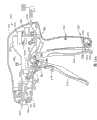
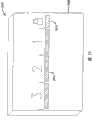
图1是外科切割和紧固器械的一种实施方式的透视图;Figure 1 is a perspective view of one embodiment of a surgical cutting and fastening instrument;
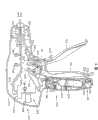
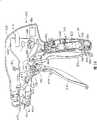
图2是可与外科切割和紧固器械的各种实施方式结合应用的端部执行器布置的一种实施方式的分解组装视图;Figure 2 is an exploded assembly view of one embodiment of an end effector arrangement usable with various embodiments of surgical cutting and fastening instruments;
图3是图1和2的端部执行器的俯视图,其中去除了砧座部分,并以虚线示出闭合管组件;Figure 3 is a top view of the end effector of Figures 1 and 2 with the anvil portion removed and the closure tube assembly shown in phantom;
图4是图3的端部执行器布置的剖面正视图,具有其上连接的砧座部分并显示为打开位置;Figure 4 is a cutaway front view of the end effector arrangement of Figure 3 with the anvil portion attached thereto and shown in an open position;
图5是可应用于外科切割和紧固器械的各种实施方式的一部分关节运动控制器的剖面俯视图;Fig. 5 is a cutaway top view of a portion of an articulation controller applicable to various embodiments of a surgical cutting and fastening instrument;
图6是示出了图1所示的端部执行器的关节运动的俯视剖面图;6 is a top sectional view illustrating articulation of the end effector shown in FIG. 1;
图7是示出了闭合管组件和支撑在手柄组件内的梭子布置的实施方式的分解组装图,为了清楚省略了外壳组件内的其他部件;Figure 7 is an exploded assembly view showing an embodiment of the closure tube assembly and shuttle arrangement supported within the handle assembly, with other components within the housing assembly omitted for clarity;
图8是外科切割和紧固器械的各种实施方式的外壳组件布置的剖面图;Figure 8 is a cross-sectional view of the housing assembly arrangement of various embodiments of a surgical cutting and fastening instrument;
图8A是可与外科切割和紧固器械的各种实施方式结合应用的一部分闭合扳机锁定系统的局部剖面图;8A is a partial cross-sectional view of a portion of a closed trigger locking system that may be used in conjunction with various embodiments of surgical cutting and fastening instruments;
图8B是外科切割和紧固器械的另一手柄组件实施方式的剖面图,其中加压气体源在手柄组件外部;8B is a cross-sectional view of another handle assembly embodiment of a surgical cutting and fastening instrument, wherein the source of pressurized gas is external to the handle assembly;
图8C是外科切割和紧固器械的另一手柄组件实施方式的剖面图;8C is a cross-sectional view of another handle assembly embodiment of a surgical cutting and fastening instrument;
图9是图8的手柄组件的另一剖面图;Figure 9 is another cross-sectional view of the handle assembly of Figure 8;
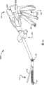
图10是刀杆布置和击发驱动构件的侧视图,该击发驱动构件包含外科切割和紧固器械的各种实施方式的两级气缸组件,气缸组件以剖面图示出;10 is a side view of a knife bar arrangement and firing drive member comprising a two-stage cylinder assembly of various embodiments of a surgical cutting and fastening instrument, shown in cross-section;
图11是图10所示的刀杆和两级气缸布置的另一侧视图,其中刀杆在伸出位置;Figure 11 is another side view of the knife bar and two-stage cylinder arrangement shown in Figure 10, with the knife bar in the extended position;
图12是外科切割和紧固器械的另一刀杆和击发驱动构件布置的侧视图,其中刀杆被回缩到以剖面图示出的气缸组件中;12 is a side view of another knife bar and firing drive member arrangement of a surgical cutting and fastening instrument with the knife bar retracted into the air cylinder assembly shown in cross-section;
图13是图12所示的刀杆和气缸布置的另一侧视图,其中刀杆在伸出位置;Figure 13 is another side view of the knife bar and cylinder arrangement shown in Figure 12, with the knife bar in the extended position;
图14是容纳图12和13中所示的气缸和刀杆布置的端部执行器和脊组件布置的俯视图;Figure 14 is a top view of the end effector and spine assembly arrangement housing the cylinder and knife bar arrangement shown in Figures 12 and 13;
图15是图14所示的端部执行器和脊组件布置的剖面侧视图,其中砧座部分连接于其上并处于打开位置;15 is a cross-sectional side view of the end effector and spine assembly arrangement shown in FIG. 14 with the anvil portion attached thereto and in an open position;
图16是可以与图12-15所示的实施方式结合使用的手柄组件的剖面图;Figure 16 is a cross-sectional view of a handle assembly that may be used in conjunction with the embodiment shown in Figures 12-15;
图16A是可以与图12-15所示的实施方式结合使用的另一手柄组件的剖面图,其中加压气体源在手柄组件的外部;Figure 16A is a cross-sectional view of another handle assembly that may be used in conjunction with the embodiment shown in Figures 12-15, wherein the source of pressurized gas is external to the handle assembly;
图16B是外科切割和紧固器械的另一手柄组件实施方式的剖面图;16B is a cross-sectional view of another handle assembly embodiment of a surgical cutting and fastening instrument;
图17是另一刀杆和支撑外科切割和紧固器械的另一实施方式的另一击发驱动构件的脊组件布置的俯视图,所述另一击发驱动构件是波纹管组件的形式;17 is a top view of another knife bar and spine assembly arrangement supporting another firing drive member of another embodiment of a surgical cutting and fastening instrument in the form of a bellows assembly;
图18是图17所示的实施方式的端部执行器和脊组件布置的剖面侧视图;Figure 18 is a cross-sectional side view of the end effector and spine assembly arrangement of the embodiment shown in Figure 17;
图19是图17和18所示的实施方式的波纹管组件的局部剖面组装视图;Figure 19 is a partially cutaway assembled view of the bellows assembly of the embodiment shown in Figures 17 and 18;
图20是图19的波纹管组件的一部分的放大视图;Figure 20 is an enlarged view of a portion of the bellows assembly of Figure 19;
图21是可以与图17-20中所示的实施方式结合使用的手柄组件实施方式的剖面图;Figure 21 is a cross-sectional view of an embodiment of a handle assembly that may be used in conjunction with the embodiment shown in Figures 17-20;
图21A是可以与图17-20中所示的实施方式结合使用的另一手柄组件实施方式的剖面图,其中加压气体源在手柄组件的外部;Figure 21A is a cross-sectional view of another handle assembly embodiment that may be used in conjunction with the embodiment shown in Figures 17-20, wherein the source of pressurized gas is external to the handle assembly;
图21B是外科切割和紧固器械的另一手柄组件实施方式的剖面图;21B is a cross-sectional view of another handle assembly embodiment of a surgical cutting and fastening instrument;
图22A和22B示出比例传感器的各种实施方式;22A and 22B illustrate various embodiments of ratiometric sensors;
图23是根据各种实施方式的器械的电路的一种实施方式的示意图;Figure 23 is a schematic diagram of one embodiment of an electrical circuit of an instrument according to various embodiments;
图24示出电控气动系统的一种实施方式;Figure 24 shows an embodiment of an electro-pneumatic system;
图25示出具有在使用过程中的一个或多个时刻处记录器械状态的能力的外科器械的各种实施方式;Figure 25 illustrates various embodiments of a surgical instrument with the ability to record the state of the instrument at one or more times during use;
图26示出闭合扳机传感器的一种实施方式;Figure 26 shows an embodiment of a closure trigger sensor;
图27示出砧座闭合传感器的一种实施方式;Figure 27 illustrates an embodiment of an anvil closure sensor;
图28示出刀位置传感器的一种实施方式,该刀位置传感器适于与从刀组件突出的气动活塞杆部分一起使用;Figure 28 illustrates one embodiment of a knife position sensor adapted for use with a pneumatic piston rod portion protruding from the knife assembly;
图29和30示出钉仓存在传感器的一种实施方式;29 and 30 illustrate an embodiment of a cartridge presence sensor;
图31A和31B示出用于操作各种实施方式的外科器械的处理流程的一种实施方式,该外科器械被构造成内镜切割器,并且具有根据各种实施方式的记录器械状态的能力;31A and 31B illustrate one embodiment of a process flow for operating various embodiments of a surgical instrument configured as an endoscopic cutter and having the ability to record the state of the instrument according to various embodiments;
图32示出来自存储装置的存储表的一种实施方式;Figure 32 shows an embodiment of a storage table from a storage device;
图33示出外科器械的各种实施方式;Figure 33 shows various embodiments of surgical instruments;
图34示出包括多个传感器的外科器械的一种实施方式的示意图;Figure 34 shows a schematic diagram of one embodiment of a surgical instrument comprising a plurality of sensors;
图35示出用于提供视觉和听觉反馈的指示器的一种实施方式;Figure 35 illustrates one embodiment of an indicator for providing visual and audible feedback;
图36示出状态模块的一种实施方式;以及Figure 36 illustrates one embodiment of a state module; and
图37示出状态模态的一种实施方式。Figure 37 shows one embodiment of a state modal.
具体实施方式Detailed ways
在一种实施方式中,气动器械包括一体的气动系统和电气控制、记录和/或反馈元件。在一种实施方式中,气动系统与电气控制系统结合,以气动致动器械并电气地控制气动系统中的流速。致动器可以用于电控气动系统的加压。控制系统接收来自源的加压气体并产生电气输出,以致动使用至少一个电气部件或元件的器械的元件。控制系统可以用于控制外科切割和紧固器械的元件。切割和紧固元件由控制器气动操作。由此,可以用加压气体和控制器来控制气压缸的致动。控制器控制加压气体在气动系统中释放的速率。控制器可以用于控制一个或多个流量控制元件,例如电磁线圈、压电致动器或者电机。这些流量控制元件可以用于打开和关闭阀以及其他闭合机构,以控制将加压气体排放到致动缸中的速度。其他的流量控制元件可以用于以可变的速率释放加压气体。这些实施方式不限于文中所述。In one embodiment, a pneumatic instrument includes an integrated pneumatic system and electrical control, recording and/or feedback elements. In one embodiment, the pneumatic system is combined with an electrical control system to pneumatically actuate the instrument and electrically control the flow rate in the pneumatic system. The actuator can be used for pressurization of the electro-pneumatic system. A control system receives pressurized gas from a source and generates an electrical output to actuate an element of an instrument using at least one electrical component or element. A control system may be used to control elements of the surgical cutting and fastening instrument. The cutting and fastening elements are operated pneumatically by the controller. Thus, the actuation of the pneumatic cylinders can be controlled with pressurized gas and a controller. The controller controls the rate at which pressurized gas is released in the pneumatic system. A controller may be used to control one or more flow control elements, such as solenoid coils, piezoelectric actuators, or motors. These flow control elements can be used to open and close valves and other closure mechanisms to control the rate at which pressurized gas is discharged into the actuating cylinder. Other flow control elements can be used to release pressurized gas at a variable rate. The embodiments are not limited to what is described herein.
在另一种实施方式中,气动器械具有电气记录能力。该器械可以包括信息记录系统,该系统例如包括电池、电路元件和与所述气动器械成为一体的存储装置。该信息记录系统可以用于记录与器械相关的信息。该器械可以包括开关、扳机、致动器或者其他的元件或技术来选择性地排放加压气体,以致动器械。在一种实施方式中,器械还可以包括一个或多个传感器来增加由记录系统收集的信息。各种传感器可以用于向信息记录系统提供信息。传感器包括用于如下事项的传感器:测量和/或记录致动和重复进行的次数、用于测量和/或记录致动或关闭器械的端部执行器的力、用于测量和/或记录端部执行器的夹钳力、用于测量和/或记录施加在组织上的压力、判断钉仓是否装载在器械中、钉仓的状态、器械的锁止状态、气压致动缸中的压力、外科器械是否准备好击发等等。这些实施方式不限于文中所述。In another embodiment, the pneumatic instrument has electrical recording capabilities. The instrument may comprise an information recording system comprising, for example, batteries, electrical circuit elements and storage means integral with said pneumatic instrument. The information recording system can be used to record information related to the device. The device may include a switch, trigger, actuator, or other element or technique to selectively discharge pressurized gas to actuate the device. In one embodiment, the instrument may also include one or more sensors to augment the information collected by the recording system. Various sensors may be used to provide information to the information logging system. Sensors include sensors for measuring and/or recording the number of actuations and repetitions, for measuring and/or recording the force to actuate or close the end effector of the instrument, for measuring and/or recording the Clamping force of external actuators, used to measure and/or record the pressure applied to the tissue, to determine whether the staple cartridge is loaded in the instrument, the state of the staple cartridge, the locking state of the instrument, the pressure in the pneumatic actuator cylinder, Whether the surgical instrument is ready to fire and so on. The embodiments are not limited to what is described herein.
在另一种实施方式中,气动器械具有电气反馈能力。气动器械可以与反馈模块成为一体。反馈模块可以是独立的并且能够连接到多个布置在器械各处的触点、电路元件和多个指示器。反馈系统、指示器、传感器和控制器可以是电动的。该器械可以包括气动或气动辅助的外科切割和紧固器械。这些实施方式不限于文中所述。In another embodiment, the pneumatic instrument has electrical feedback capability. Pneumatic instruments can be integrated with the feedback module. The feedback module may be self-contained and connectable to a number of contacts, circuit elements and a number of indicators arranged throughout the instrument. Feedback systems, indicators, sensors and controls can be electric. The instrument may comprise a pneumatic or pneumatic assisted surgical cutting and fastening instrument. The embodiments are not limited to what is described herein.
回到附图,其中相同的附图标记在所有附图中表示相同的部件,图1示出了能够实现本发明若干独特优势的外科缝合和切割器械10。图1中示出的实施方式包括手柄组件300、细长轴组件100和连接到细长轴组件100的端部执行器12。外科设备的各种实施方式可包括端部执行器,其如在2006年1月10提交的、题为“SURGICALINSTRUMENT HAVING AN ARTICULATING END EFFECTOR”的美国专利申请No.11/329,020中所公开的端部执行器一样能枢转地连接到细长轴组件100并枢转地由弯曲的线缆或带进行驱动,上述申请通过引用并入本文。然而,随着对具体实施方式的继续描述,本领域的普通技术人员应当理解,这里描述的外科设备的各种实施方式能成功地与端部执行器布置结合进行实施,所述端部执行器可采用不同的枢转机构和控制器,并且各种实施方式可成功地与非关节运动式端部执行器布置结合使用,如下面将详细解释的一样。Returning to the drawings, wherein like reference numerals refer to like parts throughout, FIG. 1 illustrates a surgical stapling and cutting
如图1中所示,器械10的手柄组件300可包括闭合扳机302和击发扳机310。应当理解,针对不同手术任务具有端部执行器的器械可具有不同数量或类型的扳机或其他用于端部执行器操作的合适控制器。所示的端部执行器12通过优选为细长轴组件100与手柄组件300分离。医生可通过利用关节运动控制器200使端部执行器12相对于轴组件100作关节运动。As shown in FIG. 1 , handle
在各种实施方式中,多个传感器可以连接到手柄组件300、细长轴组件100和/或端部执行器12中的元件上,以测量和控制器械10的各种功能,记录器械的各个部件的状态并为医生或使用者提供反馈指示。器械10包括多个传感器,其中多个传感器例如包括闭合扳机传感器、砧座闭合传感器、砧座闭合载荷传感器、刀位置传感器、仓存在传感器、仓状态传感器、击发扳机传感器和阀致动传感器或其任意组合。其他传感器可以包括关节运动角度传感器、砧座位置传感器、击发力传感器、锁止状态传感器、气压传感器、流速传感器或其任意组合。每个传感器可以与定位在外科器械10外部附近的不同触点电连通。传感器可以连接到闭合扳机302和击发扳机310上以检测它们的操作。传感器可以用于测量砧座40闭合以及砧座40上的闭合载荷。其他的传感器可以用于测量刀组件30的位置(图2)、钉仓50的存在(图2)和/或钉仓50的状态(例如用尽或尚未用尽)。其他传感器可以在器械10的各处使用,以确定器械10的致动次数、气动系统中的压力、气压缸或者致动缸的压力,并可以包括比例变动传感器以激活阀致动器等。但是,实施方式不限于文中所述的这些。In various embodiments, a plurality of sensors can be coupled to the
传感器输出信号S1至Sn(其中n是任何正整数)例如被提供给位于手柄组件中的电子控制模块603。电子控制模块603包括控制器、存储装置、电池、测量电路和/或致动器,以控制流速可变的电控气动阀的闭合机构部分,如下所述。但是,实施方式不限于文中所述的那些。The sensor output signals S1 to Sn (where n is any positive integer) are provided, for example, to an
应该理解,在此参照附图给出的空间术语诸如竖直、水平、右、左等假设外科器械10的纵向轴线与细长轴组件100的中心轴线同轴,其中扳机302、310以锐角从手柄组件300的底部向下延伸。然而,在实际应用中,可将外科器械10以各种角度定向,这样,相对于外科器械10本身使用这些空间术语。此外,“近侧”用于表示位于手柄组件300后方的医生的视角,他将端部执行器12放置在远侧或远离他自己。It should be understood that spatial terms such as vertical, horizontal, right, left, etc. given herein with reference to the figures assume that the longitudinal axis of the
如此处所用的,术语“加压气体”指适于在无菌环境下所用的气动系统中使用的任何气体。这种介质的非限制示例包括压缩空气、二氧化碳(CO2)、氮、氧、氩、氦、氢化钠、丙烷、异丁烷、丁烷、氯氟甲烷、二甲醚、甲基乙醚、一氧化氮、氢氟烷推进剂(HFA),例如HFA 134a(1,1,1,2,-四氟乙烷)或HFA 227(1,1,1,2,3,3,3-七氟丙烷)。As used herein, the term "pressurized gas" refers to any gas suitable for use in a pneumatic system used in a sterile environment. Non-limiting examples of such media include compressed air, carbon dioxide (CO2 ), nitrogen, oxygen, argon, helium, sodium hydride, propane, isobutane, butane, chlorofluoromethane, dimethyl ether, methyl ether, a Nitric oxide, hydrofluoroalkane propellants (HFA), such as HFA 134a (1,1,1,2,-tetrafluoroethane) or HFA 227 (1,1,1,2,3,3,3-heptafluoropropane) .
如此处所用的,术语“流体连接”是指元件与适合的管线或者其他部件一起连接以允许加压气体在其间通过。如此处所用的,如用在“供应管线”或“返回管线”中的术语“管线”指由刚性或柔性导管、管道和/或管材等形成的适当的通路,用于将加压气体从一个部件传送到另一部件。As used herein, the term "fluidically connected" means that elements are connected together with suitable lines or other components to allow pressurized gas to pass therebetween. As used herein, the term "line" as used in "supply line" or "return line" means a suitable passageway formed by rigid or Part transfers to another part.
如此处所用的,术语“气动信号”或“气动驱动信号”指从加压气体源到与加压气体源流体连接的一个或多个部件的气体流或者指彼此流体连接的部件之间的气体流。As used herein, the term "pneumatic signal" or "pneumatic drive signal" refers to the flow of gas from a source of pressurized gas to one or more components fluidly connected to the source of pressurized gas or to the flow of gas between components fluidly connected to each other flow.
如此处所用的,语句“基本上垂直于纵向轴线”指几乎与纵向轴线的方向垂直,其中“纵向轴线”是轴的轴线。然而,应当理解,稍微偏离垂直于纵向轴线的方向也认为基本上垂直于纵向轴线。As used herein, the phrase "substantially perpendicular to the longitudinal axis" means nearly perpendicular to the direction of the longitudinal axis, where "longitudinal axis" is the axis of the shaft. However, it should be understood that directions that deviate slightly from perpendicular to the longitudinal axis are also considered substantially perpendicular to the longitudinal axis.
图2示出了可用于外科器械10的各种实施方式中的一种气动电控工具组件或端部执行器的分解组装视图。将图1-4中所示的气动电控组件12构造成用作内镜切割器。然而,随着对具体实施方式的描述,应当理解,同样可构想将本发明实施方式的各个独特和新颖的驱动布置用于驱动被构造成执行其他手术任务的其他端部执行器,从而需要对附图中所示物体进行部件的去除、修改或增加。同样,应当理解,可以为了特定的手术应用而定制图1-4中所示的端部执行器12。FIG. 2 shows an exploded assembly view of one pneumatically-operated tool assembly or end effector that may be used in various embodiments of
图2中示出了可用于外科器械10的各种实施方式的一种类型的端部执行器。如图中所示,端部执行器12采用E形梁(E-beam)击发机构(“刀组件”)30,其除了切割组织并击发位于其中的钉仓中的缝钉,还有利地相对于钉仓控制端部执行器12的砧座部分40的间隔。在授予Shelton,IV等人的题为“Surgical Stapling InstrumentIncorporating An E-Beam Firing Mechanism”的美国专利No.6978921中描述了E形梁击发机构的各个方面,其相关部分通过引用并入本文。然而,根据对具体实施方式的描述,本领域的普通技术人员应当理解,在不脱离各实施方式的整体范围的情况下可有利地应用其他刀和击发机构构造。One type of end effector that may be used with various embodiments of
如此处所用的,术语“击发机构”是指气动电控工具和/或端部执行器的一部分或多个部分,其能够从未致动位置移动到致动位置或终端位置,在未致动位置,击发机构基本上静止,在致动位置或者终端位置,所述一部分或多个部分移动或重新定位到最终位置,其中这种移动导致工具响应施加到其上的至少一次击发运动而完成一个或多个动作。该击发机构例如可包括:(i)完全由气动电控工具支撑并与外科设备中的部件配接的部件;(ii)定位在气动工具和外科设备中的部件的组合;或(iii)由外科设备支撑并可进出气动电控工具的部件。如此处所用的,术语“击发行程”是指击发机构从未致动位置到致动位置的实际移动。术语“回缩行程”是指击发机构从致动位置到未致动位置的返回移动。As used herein, the term "firing mechanism" refers to a part or parts of a pneumatic, electrically controlled tool and/or end effector that is capable of moving from an unactuated position to an actuated position or an end position, position, the firing mechanism is substantially at rest, and in the actuated position or terminal position, the part or parts move or reposition to the final position, wherein such movement causes the implement to complete a or multiple actions. The firing mechanism may include, for example: (i) a component fully supported by a pneumatically-operated tool and mated with a component in the surgical device; (ii) a combination of components positioned in the pneumatic tool and surgical device; or (iii) composed of Components of surgical equipment that support and allow access to pneumatic and electrically controlled tools. As used herein, the term "firing stroke" refers to the actual movement of the firing mechanism from an unactuated position to an actuated position. The term "retraction stroke" refers to the return movement of the firing mechanism from the actuated position to the unactuated position.
如图2中所示,端部执行器12包括远侧构件,其在各种非限制性实施方式中包含细长通道20,该细长通道20上连接有能够可枢转地平移的砧座40。该细长通道20被构造成接收和支撑钉仓50,所述钉仓50响应刀组件30驱动缝钉70,使缝钉与砧座40成形接触。应当理解,虽然在此有利地描述了易于替换的钉仓,但是与本发明多个方面相符的钉仓可永久地固定到细长通道20中或与之一体地形成。As shown in FIG. 2 ,
在各种实施方式中,击发机构或刀组件30包括在击发过程中控制端部执行器12的间隔的竖向间隔开的销。具体地,上部销32逐步进入到砧座凹窝42中,该砧座凹窝42位于在砧座40和细长通道20之间的枢轴附近。参见图4。当被击发砧座40闭合,上部销32向远侧前进到穿过砧座40向远侧延伸的纵向砧座狭槽44中。通过上部销32施加的向下的力来克服在砧座40中的任何小的向上偏移。In various embodiments, the firing mechanism or
刀组件30还包括刀杆帽34,其向上接合形成在细长通道20中的通道狭槽23,从而与上部销32协作,以在砧座40和细长通道20之间夹紧的组织过量的情况下,将砧座40和细长通道20稍微地拉得更靠近些。在各种实施方式中,刀组件30可有利地包括中间销36,其穿过在钉仓50的下表面和细长通道20的上表面中形成的击发驱动狭槽(未显示),从而如下面所述地来驱动其中的缝钉70。中间销36通过在细长通道20上进行滑动有利地抵抗任何将端部执行器12在其远端处压紧闭合的趋势。然而,通过使用其他刀组件布置也可实现本发明各种实施方式的独特和新颖方面。The
在刀组件30上的上部销32和中间销36之间的位于远侧的切割刃38横过钉仓50中位于近侧的竖直狭槽54,以切断夹钳的组织。刀组件30相对于细长通道20和砧座40的确定定位确保执行有效的切割。在各种实施方式中,砧座40的下表面中可设有多个缝钉成形凹窝(未显示),当在细长通道内接收钉仓50时,这些缝钉成形凹窝排列成对应于钉仓50的上表面56中的多个缝钉孔58。在各种实施方式中,可将钉仓50扣合匹配到细长通道20中。具体地,钉仓50的延伸部分60、62分别摩擦地且可释放地接合细长通道20的凹槽24、26。A distally located cutting
还如图2中所示,钉仓50包含仓体51、楔形滑块64、缝钉驱动器66、缝钉70和仓盘68。当装配时,仓盘68将楔形滑块64、缝钉驱动器66和缝钉70保持在仓体51中。通过细长轴组件100将细长通道20连接到手柄组件300,该细长轴组件100包括远侧脊或框架部分110以及近侧脊或框架部分130。细长通道20在近侧设置有连接腔22,每一个连接腔22接收在远侧脊部分110的远端上所形成的相应通道锚定构件114。该细长通道20还具有枢转地接收砧座40上的相应砧座枢轴43的砧座凸轮槽28。闭合衬套组件170接收于脊组件102之上,并包括远侧闭合管部分180和近侧闭合管部分190。如下面将要描述的,闭合衬套组件170相对于脊组件102的轴向移动引起砧座40相对于细长通道20枢转。As also shown in FIG. 2 ,
如在图2中所示,将锁定弹簧112安装在远侧脊部分110上用作刀组件30的锁止件。在远侧脊部分110的顶部上形成远侧和近侧方孔111、113,在它们之间限定夹杆115,夹杆115接收锁定弹簧112的顶臂116,如下面将进一步详细讨论的,锁定弹簧112的向远侧延伸的下臂118在气缸组件501的远端上施加向下的力,该远端支撑从刀组件30突出的活塞杆部分35。应当理解,各种实施方式可包含其他类型的锁止件或根本没有锁止件。As shown in FIG. 2 , a
在图1-6所示的实施方式中,通过能够弯曲以围绕枢轴104拉动端部执行器12的多根线缆或带可使端部执行器12相对于近侧闭合管部分190(和手柄组件300)进行关节运动。本领域的普通技术人员将会理解,这种布置仅代表能与这些类型的设备结合使用的多种关节运动布置的其中之一。在该实施方式中,远侧脊部分110的近端上具有凸起122。近侧脊部分130的远端设有带贯穿其中的孔136的柄脚134。近侧脊部分130相对于远侧脊部分110进行定位,使得孔136与凸起122中的孔124共轴对齐,以便使枢轴销138能从中穿过。见图4,当组装时,这种布置允许端部执行器12相对于近侧脊部分130围绕枢轴线A-A进行枢转。In the embodiment shown in FIGS. 1-6 ,
如上所述,该实施方式采用带使端部执行器12作关节运动。具体地,带150、160可如图2和3中所示朝着关节运动枢轴104向远侧延伸。带150可沿近侧闭合管部分190的左侧穿过近侧闭合管部分190延伸,其中它途经带构件160并穿越到近侧闭合管部分190的右侧。此处,例如,带150可在连接点123处机械地连接到凸起122。同样,带160可沿近侧闭合管部分190的右侧穿过近侧闭合管部分190延伸,其中它途径带构件150并穿越到近侧闭合管部分190的左侧。此处,带160可在连接点125处机械地连接到凸起122。As noted above, this embodiment utilizes a belt to articulate the
图3是端部执行器和脊组件102的俯视图,其中闭合管组件100以虚线示出。图4是器械10的相同部分的局部剖面侧视图。如图4中所示,根据一种非限制性实施方式,所示的带150和160显示为彼此偏移以防止运动中的干扰。例如,所示出的带150处于比带160更低的位置。在另一种非限制性实施方式中,可颠倒带150和160的竖直位置。同样如图2和3中所示,带构件150围绕近侧框架部分130的柄脚部分134中的销140延伸。同样,带160围绕近侧框架部分130的柄脚部分134中的销142延伸。3 is a top view of the end effector and
带部分150和160可从凸起122延伸,并沿近侧闭合管部分190延伸到关节运动控制器200,如图5所示。关节运动控制器200可包括关节运动滑块202、框架204和封罩206。带部分150、160可借助于槽208或其他孔穿过关节运动滑块202,但是应当理解,带部分150、160可通过任何合适的手段连接到滑块202上。关节运动滑块202可以是一件式的,如图5所示,或在一种非限制性实施方式中其可以是两件式的,其中两件之间的界面限定了槽208。在一种非限制性实施方式中,关节运动滑块202可例如包括多个槽,每个槽对应其中一个带部分150、160。封罩206可覆盖控制器200的各个部件以防止碎屑进入。
在各种实施方式中,带部分150、160可在从槽208近侧定位的连接点210、212处锚定到框架204上。图5的非限制性实施方式显示带部分150、160从连接点210、212预弯曲到在近侧闭合管部分190的纵向轴线附近定位的槽208。应当理解,可将带部分150、160锚定到器械10中位于槽208近侧的任何地方,包括手柄组件300。In various embodiments,
在使用中,图2的实施方式可具有如图3所示的非关节运动位置。所示的关节运动控制器200和带150、160位于轴组件100的纵向轴线的大致中间位置上。因此,端部执行器12在中间或非关节运动位置。在图6中,显示了关节运动控制器200,其中关节运动滑块202被推动穿过关节运动框架到达轴组件100的右侧。因此,带150、160朝轴组件100的右侧弯曲。由此可知,带150向右侧的弯曲在凸起122上施加从凸起122的枢转点偏移的侧向力。该偏移的力使凸起122围绕关节运动枢轴104旋转,这又如图所示促使端部执行器12向右枢转。应当理解,将关节运动滑块202推向轴组件100的左侧可在带150、160上施加侧向力,使带150、160都朝轴组件100的左侧弯曲。接着带160的弯曲在凸起122上施加侧向力,其如上所述一样从凸起122的枢转点偏移。这又促使凸起122围绕关节运动枢轴旋转,促使端部执行器12向左枢转。In use, the embodiment of FIG. 2 may have a non-articulating position as shown in FIG. 3 .
在各种实施方式中,轴组件100包含接收在脊组件102上的闭合管组件170。参见图2。闭合管组件170包含远侧闭合管部分180和近侧闭合管部分190。远侧闭合管部分180和近侧闭合管部分190可由聚合物或其他合适的材料制造。近侧闭合管部分190是中空的并具有贯穿其中的轴向通道191,其大小适于将一部分脊组件102接收于其中。In various embodiments, the
在图2和4所示的实施方式中,使用一个双枢轴闭合接头172。应当理解,本发明并非限于双枢轴闭合接头设计,而是可包括任何合适的闭合管或衬套,或者根本没有闭合管或衬套。特别参考图4,远侧闭合管部分180具有向近侧凸出的上部和下部柄脚182、184。远侧闭合管部分180还包括马蹄形孔185和翼片186,用于接合砧座40上的砧座打开/关闭翼片46,以便如下面进一步详细讨论地促使砧座40在打开和闭合位置之间枢转。In the embodiment shown in Figures 2 and 4, a double pivot closure joint 172 is used. It should be understood that the present invention is not limited to dual pivot closure joint designs, but may include any suitable closure tube or bushing, or no closure tube or bushing at all. With particular reference to FIG. 4 , the distal
近侧闭合管部分190类似地设有向远侧延伸的上部柄脚192和向远侧延伸的下部柄脚194。上部双枢轴连接件174包括向上突出的远侧和近侧枢轴销175、176,它们分别接合向近侧突出的上部柄脚182中的上部远侧销孔183和向远侧突出的上部柄脚192中的上部近侧销孔193。接头布置还包括下部双枢轴连接件177,其具有向下突出的远侧和近侧枢轴销178、179(图2中未显示,但在图4中可见),远侧和近侧枢轴销178、179分别接合向近侧突出的下部柄脚184中的下部远侧销孔187和向远侧突出的下部柄脚194中的下部近侧销孔195。The proximal
在使用中,闭合管组件170例如响应于闭合扳机302的致动向远侧平移以闭合砧座40。通过使闭合管组件170在脊组件102上向远侧平移以闭合砧座40,促使马蹄形孔185的背部撞击砧座40上的打开/闭合翼片46,并促使它枢转到闭合位置。为了打开砧座40,在脊组件102上向近侧沿轴向移动闭合管组件170,促使翼片186接触并推靠打开/闭合翼片46,以将砧座40枢转到打开位置。在一种实施方式中,传感器可以位于闭合管组件170中,以测量施加在马蹄形孔185上的力,马蹄形孔185通过该力来撞击砧座40上的打开/闭合翼片46,使其枢转到闭合位置并将其保持在闭合位置。In use,
图7示出了外科设备的各种实施方式的非限制性手柄组件300的分解组装视图。在图7所示的实施方式中,手柄组件具有“手枪式握把”结构并包括右侧壳构件320和左侧壳构件330,右侧壳构件320和左侧壳构件330由聚合物或其他合适的材料模制或以其他方式制造并设计成匹配在一起。这种壳构件320和330可通过扣合部件、模制的栓和座或在内部形成的其他方式、通过粘合剂、螺钉、螺栓和/或夹具连接在一起。右侧壳构件320的上部322与左侧壳构件330的对应的上部323匹配以形成表示为340的主外壳部分。类似地,右侧壳构件320的下握持部324与左侧壳构件的对应的下握持部334匹配以形成整体表示为342的握持部。在图7所示的实施方式中,整个握持部342与主外壳部分340形成一体。这种布置特别适于加压气体源永久安装到握持部342中的应用。这种布置还适合用于如下的加压气体源:它在手柄组件300的外部并通过外壳组件上的一个或多个端口插入到容纳在其中的控制部件中。在其他实施方式中,如下面进一步详细描述的,握持部342可从主外壳部分340上拆除。根据对具体实施方式的描述应当理解,这种布置提供了众多的好处和优势。然而,本领域的普通技术人员应当理解,可以提供具有不同形状和大小的手柄组件300。FIG. 7 shows an exploded assembly view of a
为了清楚起见,图7仅示出了用于控制闭合管组件170轴向移动的部件,其最终控制砧座40的打开和闭合。如图7所示,通过连接组件430连接于闭合扳机302上的闭合梭400支撑在主外壳部分340中。闭合梭400同样可制造成两件402、404,它们由聚合物或其他合适的材料模制或以其他方式制造并设计为互相匹配。例如,在图7示出的实施方式中,右侧部分402设有紧固柱403,其被设计用来接收到左侧部分404中对应的凹口(未显示)内。右侧部分402和左侧部分404可通过扣合构件和/或粘合剂和/或螺栓、螺钉和/或夹具以其他方式保持在一起。如图7所示,在近侧闭合管部分190的近端中设有保持沟槽196。闭合梭400的右侧部分402具有右保持凸缘部分405,其适于与闭合梭400的左侧部分404上的左保持凸缘部分(未显示)协作,以形成延伸进入近侧闭合管部分190的保持沟槽196中的保持凸缘组件。For clarity, FIG. 7 shows only the components used to control the axial movement of the
如图7中所示,右脊组件保持栓326从右侧壳构件320向内突出。这种栓326伸入闭合梭400的右侧部分402中的细长槽或窗406中。类似的闭合梭保持栓(未显示)从左侧壳构件330向内突出,以被接收于闭合梭400的左侧部分404中所设的另一窗或槽408中。保持栓用于将近侧脊部分130的近端133(图7未显示)不可移动地固定在手柄组件300上,同时允许闭合梭400相对于它轴向移动。例如通过螺栓、螺钉、粘合剂和/或扣合部件等可将保持栓机械地连接到近侧脊部分130的近端。另外,闭合梭400设有侧向延伸的导轨410、411。导轨410被构造成可滑动地接收于右侧壳构件320的导轨导向件328中,并且导轨411被构造成可滑动地接收于左侧壳构件330的导轨导向件(未显示)中。As shown in FIG. 7 , the right spine
通过朝手柄组件300的握持部342移动闭合扳机302来产生闭合梭400和闭合管组件170向远侧(箭头“C”)沿轴向的移动,并且通过将闭合扳机302远离握持部342移动来产生闭合梭400向近侧(箭头“D”)沿轴向的移动。在各种实施方式中,闭合梭400设有方便连接闭合连接组件430的连接器翼片412。参见图8和9。闭合连接组件430包括通过销414枢转地销接到连接器翼片412上的轭部432。闭合连接组件430还具有闭合臂434,如图7中所示,闭合臂434通过闭合销436枢转地销接到在闭合扳机302上形成的轭组件304上。通过在右侧壳构件320和左侧壳构件330之间延伸的枢轴销306,将闭合扳机302枢转地安装在手柄组件300内。Axial movement of the
当医生想要闭合砧座40以夹钳端部执行器12中的组织时,医生朝握持部342拉动闭合扳机302。当医生朝握持部342拉动闭合扳机302时,闭合连接组件430在远侧方向“C”上移动闭合梭400,直到闭合连接组件430移入图8所示的锁定位置内。当在这一位置中时,闭合连接组件430倾向于将闭合梭400保持在该锁定位置上。当闭合梭400移到锁定位置时,闭合管组件170在脊组件102上向远侧移动,促使远侧闭合管部分180内的马蹄形孔185的近端接触砧座40上的闭合/打开翼片46,从而将砧座40枢转到闭合(夹钳)位置。When the physician wishes to close
在各种实施方式中,为了进一步将闭合梭400保持在闭合位置上,闭合扳机302可设有可释放的锁定机构301,其适于接合握持部342和可释放地将闭合扳机302保持在锁定位置上。其他锁定装置也可用于可释放地将闭合梭400保持在锁定位置上。在图8、8A、8B和9所示的实施方式中,闭合扳机302包括柔性纵向臂303,其包括从其延伸的侧销305。例如,臂303和销305可由模制塑料制成。手柄组件300的手枪式握持部342包括开口350,在其中设置有侧向延伸的楔块352。当回缩闭合扳机302时,销305接合楔块352,并且楔块352的下表面354迫使销305向下(即,臂303顺时针旋转)。当销305完全通过下表面354时,去除臂303上的顺时针的力,并且销305逆时针旋转,使得销305停靠在楔块352后的凹口356中,从而锁定闭合扳机302。通过从楔块352延伸的柔性挡块358进一步将销305保持在锁定位置中。In various embodiments, to further maintain the
为了解锁闭合扳机302,操作者可进一步挤压闭合扳机302,促使销305接合开口350的倾斜后壁359,迫使销305向上经过柔性挡块358。接着销305可自由地穿出开口360中的上部通道,使得闭合扳机302不再锁定到手枪式握持部342上。在Shelton,IV等人于2006年1月31日提交的题为“Surgical Instrument Having A RemovableBattery”的美国专利申请No.11/344020中公开了这种布置的其他细节,该申请的相关部分通过引用并入本文。还可应用其他可释放的锁定布置。To unlock the
在外科设备的各种实施方式中,刀组件30可具有从其上突出或以其他方式与其连接的基本上为刚性的活塞杆部35,其是驱动构件500的一部分,驱动构件500由远侧脊部分110可操作地支撑并被构造成向刀组件30施加至少两个致动动作(例如击发动作和回缩动作)。在图3、4、10和11所示的实施方式中,驱动构件500包含两级气动气缸组件501。刀组件30可由一个整体部件构成或可被设置成由多个部件构成以使器械10的组装更容易。例如,如图10和11所示,刀组件30包含远侧部分31,其包含上部销32、帽34、中间销36和刀38。远侧部分31可设有孔33,其大小适于接收在活塞杆部35的远端上设置的突起37。突起37可摩擦地接收于孔33中和/或通过粘合和/或焊接等保持在其中。In various embodiments of the surgical device, the
气缸组件501包含第一气缸外壳510,其具有闭合的第一近端512和通入位于第一气缸外壳510中的第一轴向通道516内的打开的第一远端514。气缸组件501还包含第二气缸外壳520,其具有第二近端522和通入第二轴向通道526的打开的第二远端524。闭合的第二近端522上形成有第一活塞头528,该活塞头相对于第一轴向通道516的大小适于与第一气缸外壳510的第一壁511产生基本气密的滑动密封,从而在第一近端512的远侧与第一活塞头528的近侧之间限定第一气缸区域515。第一气缸外壳510的第一远端514上还形成有向内延伸的第一凸缘517,用于与第二气缸外壳520的外壁表面建立基本气密的滑动密封,从而在第一凸缘517的近侧和第一活塞头528的远侧之间限定第二气缸区域518。The
穿过第一活塞头528设置第一通道527。如图10和11中所示,活塞杆35的近端延伸穿过第二气缸外壳520的打开的第二远端524并进入第二轴向通道526。第二活塞头530形成于或以其他方式连接于活塞杆35的近端。第二活塞头530相对于第二轴向通道526的大小适于与第二气缸外壳520的第二壁521建立基本气密的滑动密封,以限定第三气缸区域532。第二气缸外壳520的第二远端524上还形成有向内延伸的第二凸缘525,用于与活塞杆35建立基本气密的滑动密封,以在第二凸缘525的近侧和第二活塞头530的远侧之间限定第四气缸区域534。A
如图3和4中所示,气缸组件501被安装到远侧脊部分110内。在各种实施方式中,在第一气缸外壳510的近端上设置一对凸耳519。凸耳519被接收在远侧脊部分110的凸耳孔119中,从而使气缸组件501能在远侧脊部分110内围绕枢转轴线B-B枢转。参见图3。第一供应管线或供应管路540从手柄组件300中的方向控制阀610(图8和9)延伸穿过近侧闭合管部分190,以连接到第一气缸外壳510的第一近端512上,以便通过第一气缸外壳510的第一近端512中的第一供应端口513或开口供应加压气体。参见图10和11。在一种实施方式中,压力传感器可以流体连接到第一供应管线540以测量或感测第一供应管线540中的压力(P)。压力传感器向电子控制模块603提供与第一供应管线540中的压力成比例的电反馈信号。另外,第二供应管线542从方向控制阀610延伸穿过近侧闭合管部分190并连接于第一气缸外壳510的远端514附近,从而通过第二端口529将加压气体供应给第二气缸区域518。在一种实施方式中,压力传感器可以流体连接到第二供应管线542,以测量或感测第二供应管线542中的压力(P)。压力传感器向电子控制模块603提供与第二供应管线542中的压力成比例的电反馈信号。其他压力传感器可以流体连接到整个气动系统。例如,压力传感器可以分别流体连接到第一和第二压力供应端口513、529,以测量第一和第二气缸区域515、518各自中的压力。以此方式,可以测量两级气缸组件501中的压力,并将该压力作为反馈信号提供给电子控制模块603。As shown in FIGS. 3 and 4 , the
参考图8-11和26,现在将描述击发机构或刀组件30的伸出和回缩。如图8和9中所示,供应管线540和542连接于电控方向阀610上,该方向阀610是容纳在手柄外壳350内的致动器系统600的一部分。致动器系统600包括致动扳机670、方向阀610和流速可变的电控气动阀660。这些元件连接到电子控制模块603上。电子控制模块603接受来自分布在整个器械10中的各个传感器的反馈信号。电子控制模块603基于反馈信号向分布在整个器械10中的各个控制元件提供控制信号。在一种实施方式中,电子控制模块603包括控制器702、存储装置703、电池704、测量电路732和/或致动器706,以控制流速可变的电控气动阀660的闭合机构部分730。见图26。但是,这些实施方式的内容不限于所描述的内容。在一种实施方式中,致动器系统600可以与状态模块2408(以下参考图33-37描述)通信。在各种实施方式中,方向阀610可由电子控制模块603进行电气控制。在其他实施方式中,方向阀可以通过穿过手柄外壳350接近的选择器开关612或推动按钮而手动地在前向(伸出)和反向(回缩)位置之间进行切换。在一种实施方式中,选择器开关612或合适的按钮可以以电的形式实现,用于产生表示方向阀610的所需状态的信号。该信号可以耦合到控制器702,其产生阀方向控制信号以控制方向阀610。在图8和9所示的实施方式中,使用可去除的加压气体源620。如下面将进一步讨论的,这种加压气体源包括能用优选的加压气体再填充的气缸622。然而,本领域的普通技术人员应当理解,同样可有效地应用不可更换/可再填充的加压气体源(气缸)。在其他实施方式中,手柄组件300可设有端口616,以从外部加压气体源618供应加压气体。例如,器械10可通过柔性供应管线617连接到设备的压缩气体供应源618。参见图8B。在一种实施方式中,压力传感器可以流体连接到可去除的源622的出口,或者设备的压缩气体供应源618,以测量或者感测输入供应管线650中的压力。压力传感器向电子控制模块603提供与输入供应管线650中的压力成比例的电反馈信号。Referring to Figures 8-11 and 26, extension and retraction of the firing mechanism or
下面将进一步讨论可去除/可再填充气缸622的独特和新颖的方面。然而,为了便于解释活塞杆35和刀组件30的伸出和回缩,可以看出来自气缸622(或外部压力源618)的加压气体流穿过供应管线650进入流速可变的电控气动阀660。流速可变的电控气动阀660由控制器702控制。特别如图9所示,流速可变的气动阀660连接到由致动扳机670致动的阀致动传感器662上。阀致动传感器662可以是数字的或模拟的传感器,其连接到控制器702上。在图示的实施方式中,阀致动传感器662是比例传感器,其提供与流过流速可变的电控气动阀660的所需流速成比例的电信号。当阀致动传感器662检测到致动扳机670的运动时,其向控制器702发送与从气缸622流入供应管线680从而进入第一或第二供应管线540、542的加压气体的所需流速成比例的电信号。控制器702调节流速可变的气动阀660中的流量控制元件以产生加压气体的所需流速。在一种实施方式中,压力传感器可以流体连接到供应管线680,以测量或感测供应管线680中的压力。压力传感器向电子控制模块603提供与供应管线680中的压力成比例的电反馈信号。如这里所使用的,术语“流速可变的致动组件”至少包括流速可变的气动阀660、致动扳机670、控制器702、电池704和致动器706以及它们各自等同的结构。The unique and novel aspects of the removable/
阀致动传感器662(见图22A、22B)与致动扳机670连通,以检测操作者何时朝向手柄的下握持部324拉(或“闭合”)致动扳机670,用于以电控的方式气动致动端部执行器12的切割/缝合操作。阀致动传感器662可以是比例传感器,例如可变电阻器或变阻器。当拉紧致动扳机670时,阀致动传感器662检测该运动,并将电信号发送给控制器702或者存储装置703,该电信号表示通过气动系统的所需压力或流速。控制器702向致动器706发送电致动信号,以控制流过流速可变的气动阀660的流速。当阀致动传感器662是可变电阻器等时,致动信号可以基本上与致动扳机670的运动量成比例。就是说,如果操作者只略微拉动或者闭合致动扳机670,则致动信号以及流速相对较小。当致动扳机670被完全拉紧(或者到达完全闭合位置)时,致动信号以及流速到达最大。换言之,使用者越用力拉动致动扳机670,致动信号越大,使得通过流速可变的气动阀660的流速越大。A valve actuation sensor 662 (see FIGS. 22A, 22B ) communicates with the
致动器706可以包括任何合适类型的致动机构,包括电机、合适的减速装置、气动致动器、电磁线圈、压电致动器以及任何合适的能够将潜在的能源(例如电或者压缩空气)转换成适于驱动闭合机构730(图24)的物理位移的装置。
图22A和22B示出了比例传感器的各种实施方式。在图示的实施方式中,图22A和22B示出了比例传感器的两种状态,这些比例传感器可以用作根据器械的各种实施方式的阀致动传感器662。阀致动传感器662可以包括面部708、第一电极(A)710、第二电极(B)712以及位于电极710、712之间的可压缩电介质材料714,例如电活化聚合物(EAP)。阀致动传感器662可以定位成使得在回缩时面部708接触致动扳机670。由此,当回缩致动扳机670时,压缩电介质材料714,如图22B所示,使得电极710、712更加靠近。因为电极710、712之间的距离“b”与电极710、712之间的阻抗直接相关,该距离越大,阻抗越大,该距离越小,阻抗越小。以此方式,由于致动扳机670的回缩(图22B中以力“F”来表示)而被压缩的电介质714的量与电极710、712之间的阻抗成比例,这可以用于比例控制流速可变的气动阀660。Figures 22A and 22B illustrate various embodiments of proportional sensors. In the illustrated embodiment, Figures 22A and 22B show two states of a proportional sensor that may be used as the
图23是根据各种实施方式的器械10的电路的一种实施方式的示意图。当操作者在锁定闭合扳机302之后初始拉紧击发扳机310时,通过挤压致动扳机670来致动该致动传感器662。这允许加压气体在致动器706和控制器702的控制下流过流速可变的气动阀660。如果常开的行程结束传感器716是断开的(意味着还没有到达端部执行器的行程末端),加压气体将通过第一供应管路540流过流速可变的气动阀660。因为传感器开关716常开并且其未闭合,所以继电器720的感应器718将不会被供电,因此继电器720将处于未被激发的状态。该电路还包括钉仓锁止传感器722。如果端部执行器12包括钉仓50,传感器722将处于闭合状态,允许电流流过。否则,如果端部执行器12不包括钉仓50,传感器722将断开,由此阻止电池704向致动器706供电。Figure 23 is a schematic diagram of one embodiment of the electrical circuitry of the
当存在钉仓50时,传感器722闭合并激活单刀单掷继电器724。当继电器724被激活时,电流流过继电器724并流过阀致动传感器662(示作可变电阻器)。逻辑电路726接收来自传感器开关716、继电器720、传感器722、单掷继电器724以及阀致动传感器662的输入,并以数字的形式向控制器702提供信息。控制器702使用该信息来产生控制信号746(图24),以保持方向控制阀610的致动,从而允许加压气体流入第一供应管线540,使得端部执行器保持其从近端向远端的向前方向。When the
当端部执行器12到达其行程末端时,传感器开关716将被激活,由此激活继电器720。这使得继电器720处于其激活的状态(图23中未示出),从而使电流绕过钉仓锁止传感器722和阀致动传感器662。控制器702现在用控制信号796(图24)致动方向控制阀610,以允许加压气体流入第二供应管线542,从而使端部执行器将其方向反向为从远端朝向近端。When the
因为行程开始传感器728是常闭的,所以电流将流回到感应器718,以保持其闭合直到行程开始传感器728断开。当刀组件30完全回缩时,行程开始传感器728被激活,使得传感器728断开。然后,控制器702提供信号,以使致动器706切断流速可变的气动阀660。Since the start of
在其他实施方式中,代替模拟的比例式阀致动传感器662,可以使用数字开闭式的传感器。在这样的实施方式中,闭合机构730可以独立于由操作者施加的力来打开至其完全流速或者闭合至基本上零流速。当完全打开时,流速可变的气动阀660通常将提供恒定的流速。操作者将感受到力反馈,因为击发扳机670被调整到齿轮传动系中。In other embodiments, instead of the analog proportional
现在回到图8-11,在各种实施方式中,致动扳机670被支撑在激发扳机310的附近,该击发扳机310通过枢轴销370可枢转地连接到手柄组件300上,该枢轴销370在右侧壳构件320和左侧壳构件330之间延伸。朝向击发扳机310向内挤压致动扳机670将致动阀致动传感器662,其向控制器702提供比例信号,以调节致动器706并由此调节流速可变的气动阀660,以增加从气缸622流向与方向阀610相连的供应管线680的加压气体的流速。根据方向阀610的位置,加压气体将流入供应管线540或542。例如,当医生通过致动致动扳机670来致动方向阀610以击发刀组件30时,允许加压气体以由控制器702控制的速率流过流速可变的气动阀660,流向供应管线540并通过第一活塞头528中的第一开口527进入第一气缸区域515并进入第三气缸区域532。在一种实施方式中,压力传感器可以流体连接到第一活塞头528,以感测和测量第一活塞头528处的压力。当加压气体进入第三气缸区域532时,第二活塞头530向远侧推动活塞杆35。在一种实施方式中,压力传感器也可以流体连接到第二活塞头530,以测量和感测第二活塞头530处的压力。位于第四气缸区域中的气体通过第二气缸外壳520中的排气口523从其排放。类似地,包含在第二气缸区域518中的气体被允许通过第二开口529从其排放到第二供应管线542中。第二供应管线542将所排放的气体输送至方向阀610,气体最终从这里排放。继续向第一气缸区域515和第三气缸区域532施加加压气体使得刀组件30完全伸出穿过端部执行器12。当刀组件30穿过端部执行器12时,其切割夹钳在其中的组织并击发钉仓50中的缝钉70(驱动缝钉与砧座40的下表面成形接触)。一旦刀组件30被推进到其在端部执行器12中的最远侧位置,医生通过释放致动扳机670来停止施加加压气体。Returning now to FIGS. 8-11, in various embodiments, the
为了回缩击发机构或刀组件30,医生手动移动选择器开关612或合适的按钮,以便将方向阀610调整到回缩位置,并开始挤压致动扳机670,这促使加压气体流入第二供应管线542。流过第二供应管线542的气体进入第二气缸区域518,这促使第二气缸外壳520向近侧回缩到第一气缸外壳510中。允许第一气缸区域515中的气体通过第一供应开口513排入第一供应管线540中。气体穿过第一供应管线540进入方向阀610,在此将其排出。如图10所示,一旦进入第二气缸区域518的加压气体促使第二气缸外壳520回缩到第一气缸外壳510中,则穿过第二开口529的气体现在能够穿过第一气缸外壳510中的排气口523并进入到第四气缸区域534。当加压气体进入第四气缸区域534中时,第二活塞头530将活塞杆35向近侧拉入第二气缸外壳520中。第三气缸区域532中的气体穿过第一开口527进入第一气缸区域515,从这里将其以上面所述方式排出。To retract the firing mechanism or
该器械各种实施方式的以流速可变的气动阀660的形式存在的流速可变的阀可采用各种电控元件或部件(未显示)来将流速可变的气动阀660偏压到未致动的位置。当位于未致动的位置时,流速可变的气动阀660可被构造成防止任何来自气体源620或618的气体流过流速可变的气动阀660内的孔(未显示)。这样,当致动扳机670处于未致动位置时,该设备基本上处于关闭状态。The variable flow rate valve of various embodiments of the apparatus in the form of the variable flow rate
图24示出了电控气动系统700的一种实施方式。气动系统700包括内部或者外部加压气体源。在图示的实施方式中,气动系统700包括气缸622作为可以用优选的加压气体来再填充的加压气体源。也可以有效地使用不可更换/可再填充的加压气体源(气缸)。在其他实施方式中,手柄组件300可以设置有端口616,用于从外部加压气体源618供应加压气体。电子控制模块603与传感器和流量控制元件电连通,以控制通过流速可变的气动阀660(和方向控制阀610)的流速。例如,电子控制模块603基于从多个传感器接收的反馈信号S1至Sn和从多个压力传感器接收的多个压力测量信号P1至Pm来提供流量控制信号,其中n和m是正整数。在一种实施方式中,气动系统与第一和第二供应管线540、542以及测量电路732流体连通。测量电路732从流速可变的气动阀660以及第一和第二供应管线540、542接收压力信号P1至Pm,并向控制器702提供与气动系统中的流速成比例的反馈信号736。测量电路732提供数字或者任何合适形式的反馈信号736。FIG. 24 illustrates one embodiment of an electropneumatic system 700 . Pneumatic system 700 includes an internal or external source of pressurized gas. In the illustrated embodiment, pneumatic system 700 includes
在一种实施方式中,测量电路732从流体连接在气动系统各处的各个压力传感器接收压力输入P1、P2、P4、P5....Pm。例如,压力传感器5411可以在闭合机构730上游处在阀660的入口部分处流体连接到输入供应管线650上,以测量入口压力P1,在一种实施方式中,入口压力P1与供应源622的压力相同。压力传感器5412可以流体连接到阀660的出口上以测量供应管线680中位于闭合机构730的下游侧处的压力P2。来自这些压力传感器5411和5412的输出电信号也可以用于确定闭合机构730上的压差,即ΔP=(P2-P1)。在其他实施方式中,压力传感器5411和5412可以构造成单个压差传感器。基于穿过孔的压差ΔP来计算通过孔的流速的方法是已知的。压力传感器5413可以流体连接到方向控制阀610的第一出口,以测量第一供应管线540中的压力P3。压力传感器5414可以流体连接到方向控制阀610的第二出口,以测量第二供应管线542中的压力P4。其他的压力传感器541m可以流体连接到整个气动系统中以测量气动系统中相应的压力Pm。在一种实施方式中,控制器702和/或测量电路732也从布置在器械10各处的多个传感器接收反馈信号S1至Sn。这些传感器可以包括限位开关、固态开关、继电器和/或流量传感器。In one embodiment, the
在各种实施方式中,控制器702从测量电路732接收反馈信号736。反馈信号736与通过流速可变的气动阀660的流速成比例,并可以基于从各个压力传感器5411至541m测量的压力P1至Pm。控制器702产生控制信号738,该控制信号738被提供给致动器706以控制闭合机构730,该控制信号738用于设定通过流速可变的气动阀660的流速。控制器702可以包括微处理器以执行合适的控制算法,用于使由测量电路732提供的实际流速反馈信号736与提供给致动器706的激活控制信号738相关,从而控制闭合机构730实现以所需的流速流过流速可变的气动阀660的流通部分。控制算法可以是任何合适的比例、微分、积分控制算法或其组合。In various implementations, the
致动器706发送控制信号740以致动位于流速可变的气动阀660的流通部分734的流动路径742中的闭合机构730。流速可变的气动阀660可以包括位于流通部分734的流动路径742中的各种类型的电动闭合机构730,以控制通过其排放气体的速度。闭合机构730、压力传感器P1至Pm以及测量电路732、控制器702和致动器706形成闭合的回路控制系统,以控制通过气动系统排放气体的速度。闭合机构730包括诸如一个或多个电磁线圈、压电致动器或电机或其组合之类的电控元件或部件。这些电控元件或部件由控制器702和致动器706可操作地控制,以选择性地控制闭合机构730。通过流速可变的气动阀660进入包含致动气缸组件501的气动驱动构件500中的气体的流速或者排放速度可以由闭合机构730的状态和整个气动系统中的压力来确定。控制器702还产生用于方向控制阀610的控制信号746,以选择第一供应管路540或者第二供应管路542作为气体排放路径。可以通过此来控制致动气缸组件501在行程开始或者行程结束时的方向。在一种实施方式中,控制器702可以控制电磁线圈或压电致动器的致动,以控制加压气体通过流速可变的排放阀660的排放气体的速度。
在各种实施方式中,闭合机构730可以包括电磁线圈或者压电致动器。由此,控制器702可以被构造成向致动器706提供一系列电脉冲形式的控制信号738,该致动器706适于以脉冲的方式致动电磁线圈或者压电致动器。致动器706可以包括脉冲驱动电路,以用一系列电脉冲来适当地驱动电磁线圈或者压电致动器。为了增加或者减小流速,控制器702分别增加或者减小脉冲的频率。致动器706向电磁线圈或者压电致动器施加脉冲。In various implementations, the closure mechanism 730 may include an electromagnetic coil or a piezoelectric actuator. Thus, the
在其他实施方式中,闭合机构730可以包括带有可控的可变内孔的元件,该内孔位于流速可变的气动阀660的流通部分734中。一种这样的闭合机构可以是由电机驱动的隔膜型膜片控制阀。隔膜型膜片控制阀(流量阀)包括大量指状物或者叶片,它们延伸到流通部分734中并形成具有可变的孔的圆形隔板,该可变的孔通过连接到隔膜型膜片流量阀上电机的转动来控制。指状物延伸到流动路径742中的程度控制孔的半径,并由此控制可以从其流过的流体量和通过该流速可变的气动阀660的流速。用于该隔膜型阀的致动器706可以是适于并被构造成驱动隔膜型阀的电机。由此,电机控制可变的开口或孔的直径,以控制加压气体在该流速可变的气动阀660的流通部分734中的排放速度。该阀的孔的直径可以通过控制器702来设定,用于实现所需的流速。实际的流速可以由测量电路732基于从各个压力传感器5411至5414测量的压力P1至Pm和/或来自其他传感器(例如布置在气动系统中各处的各种流量传感器)的信号S1至Sn来确定。在一种实施方式中,通过流通部分734的流速可以基于阀的孔的直径和经过孔的压差ΔP(P2到P1)来确定。基于反馈信号736,控制器702向致动器730提供控制信号738,该致动器730适于控制阀电机。通过向隔膜型阀机构提供合适的控制信号以设定内孔直径从而产生所需的流速,致动器730将设定所需的气体排放流速。In other embodiments, the closure mechanism 730 may comprise an element with a controllable variable bore located in the flow-through portion 734 of the variable flow rate
本领域技术人员应当理解,信息可以根据合适的通信协议在整个电控气动系统中进行传输。这种协议的示例包括HART
在上述的实施方式中,流速可变的气动阀660可以电气连接到致动扳机670和阀致动传感器662上。致动扳机670和致动传感器662连接到控制器702上。阀致动传感器662连接到致动扳机670,以检测操作者何时朝向手柄组件300的手枪式握持部324拉(或“闭合”)致动扳机670,用以致动端部执行器12的切割/缝合操作。阀致动传感器662可以是比例传感器,例如可变电阻器或变阻器。当拉紧致动扳机670时,阀致动传感器662检测该运动,并发送电信号,该电信号表示待由流速可变的气动阀600供应到气动致动气缸组件501的加压气体的所需排放速度。当阀致动传感器662是可变电阻器等时,致动器706的输出基本上可以与致动扳机670的运动量成比例。就是说,如果操作者略微拉动或者闭合致动扳机670,则致动器706的输出相对较小(例如低流速)。当致动扳机670被完全拉紧(或者到达完全闭合位置)时,致动器706的输出达到最大(例如最高的流速)。换言之,使用者越用力拉动致动扳机670,施加到致动器706上的致动信号越大,使得通过流速可变的气动阀660的流通部分734的气体排放速度越大。由此,当医生朝向击发扳机310向内挤压致动扳机670时,阀致动传感器662向控制器702提供比例信号,控制器702向致动器706发送控制信号738以致动闭合机构730。作为响应,流速可变的气动阀660的闭合机构730允许通过其的气体流速增大。因此,快速挤压致动扳机670可以使装置的击发速度增加并且降低挤压致动扳机670的速度可以使击发速度降低。因此,允许流过流速可变的气动阀660的气体量可以与施加到致动扳机670上的手动力的大小基本上成比例。In the embodiments described above, the variable flow rate
在其他实施方式中,可电子地控制流速可变的气动阀660,使得一旦致动扳机被致动,则流速可变的气动阀660数字化地从其喷射气体。流速可变的气动阀660以脉冲的方式释放少量的气体,并且挤压致动扳机670越有力,则脉冲越密。这种布置用于可选择地调节用于致动设备的气体体积。In other embodiments, the variable flow
同样,在其他实施方式中,致动机构可包含不同类型的机构,其不会像致动扳机670一样相对于手柄组件可枢转地受到支撑。例如,致动扳机可包含弹簧致动的滑动开关等。因此,对本发明那些实施方式的保护并不仅仅限定为应用枢转致动的扳机的实施方式。Likewise, in other embodiments, the actuation mechanism may comprise a different type of mechanism that is not pivotally supported relative to the handle assembly as the
此外,在各种实施方式中,每个压力传感器5411至541m可以连接至视觉显示器,以显示如图8和26所示气动系统中的任何供应管线650、680、540、542中测量的压力P1至Pm。该显示器向医生提供了各个压力传感器5411至541m的压力读数P1至Pm的视觉指示。可以穿过手柄组件300的相应部分设置一个或多个窗口,以使医生能够在使用过程中观察由压力传感器5411显示的压力,或者其他布置可以用于使医生能够观察由压力传感器5411显示的压力。在各种实施方式中,压力显示器可以连接到附加的电路上,以向控制器702提供各个供应管线650、680、540、542的压力读数P1至Pm的电信号指示。在这些非限制性的实施方式中,压力传感器5411至541m向控制器702提供反馈信号P1至Pm,压力显示器向医生提供击发行程中所遇到的力的反馈。本领域技术人员应当理解,在一些非限制性的实施方式中,致动击发机构所需的力与气缸组件501中的压力直接成比例。如果这些力较小,则气缸组件501不需要较大的压力来致动。另一方面,如果致动气缸组件501的力较高,则更多的气体将必须被释放到气缸组件501中,以增加其中的压力,用于完全致动击发机构。压力显示器用于向医生提供与端部执行器所经历的力成比例的读数。Additionally, in various embodiments, each pressure sensor5411 to 541m can be connected to a visual display to show the pressure measured in any
在其他各种实施方式中,如图8C所示,在供应管线540上设有可听出口545。这种可听出口允许少量气体从供应管线540中释放。随压力的增加,必然使由气体释放所产生的笛音音调增高。然后医生可将笛音音调与击发机构所经受的力关联起来。这样,这种布置给医生提供了听觉反馈机构,用于监视驱动系统500所经受的击发力并最终监视击发机构所经受的击发力。In various other embodiments, an
各种非限制性实施方式同样可设有在击发机构已经到达击发行程末端时自动通知医生的部件。例如,如图4所示,可将限位开关546设在远侧脊部分110内,用于检测嵌入或以其他方式连接到击发杆35上的致动构件547,如图11所示。致动构件547定位成使得当击发杆35和击发机构达到击发行程末端时,由限位开关546检测致动构件547,限位开关546可电连接到控制器702和方向控制阀610,用于给它们传送适当的信号Sn。当接收到这种信号Sn时,方向控制阀610能够自动移到回缩位置并允许击发机构回缩。另外,限位开关546可连接到图8中整体表示为549的指示构件。在各种实施方式中,该指示构件可给医生提供听觉信号、视觉信号或听觉和视觉信号的组合,以指示击发机构已经达到击发行程末端。例如,该指示构件可包含发声设备、发光二极管、振动产生设备和/或这些设备的组合。限位开关546和相关的控制部件可由支撑在外壳组件300中的电池704供电或者它可由外部电源进行供电。这样,本发明的各种非限制性实施方式可设有给医生提供指示击发机构已经达到击发行程末端的视觉和/听觉信号的部件、和/或自动气动地将击发机构回缩到未致动位置的部件。Various non-limiting embodiments may also be provided with features that automatically notify the physician when the firing mechanism has reached the end of the firing stroke. For example, as shown in FIG. 4 , a
如图4、10和11中所示,在活塞杆35的底部上可形成锁定突起39。当刀组件30在如图4所示的完全回缩位置时,锁定弹簧112的臂118给气缸组件501的远端施加偏压力。因为气缸组件501通过凸耳519可枢转地安装在远侧脊部分110上,所以气缸组件501的远端在远侧脊部分110内向下枢转并进一步使活塞杆35上的锁定突起39进入细长通道20内的锁定开口21中。通过锁定突起39与细长通道20的其中限定了锁定开口的部分的摩擦接合,这种布置将刀组件30锁在回缩位置上。如图10和11所示,锁定突起39具有近侧斜面39’和远侧斜面39”,使锁定突起能够轻易地进入和退出细长通道20中的锁定开口。本领域的普通技术人员应当理解,在不脱离本发明的精神和范围的情况下,也可成功地应用其他刀杆锁定布置。As shown in FIGS. 4 , 10 and 11 , a locking
图12-16A示出了器械的另一实施方式,其中驱动构件500包含气缸组件800,其除了下述方面外,结构类似于上述气缸组件501。例如,在该实施方式中,弹簧850、852用于回缩活塞杆35。如图12和13所示,气缸组件800包括第一外壳810,其具有闭合的第一端812和贯穿其中的第一供应端口813。第一供应管线840连接到闭合的第一端812上以通过第一供应端口813供应加压气体。在该实施方式中,第一气缸外壳810没有上述各种实施方式中描述的第二开口529。第二气缸外壳820滑动地接收于第一气缸外壳810中,并具有其上形成有第一活塞头828的闭合的第二近端822。在闭合的第一端812和第一活塞头828之间限定了第一气缸区域815。在第一活塞头828和形成于第一气缸外壳810远端上的第一凸缘817之间设有第一回缩弹簧850。第一回缩弹簧850用来将第二气缸外壳820偏压到第一气缸810中的回缩位置上,如图12所示。活塞杆35具有阶梯式端部35’,其大小适于进入第二气缸外壳820的第二远端824中。在第二远端824上形成第二凸缘825以基本实现与活塞杆35的阶梯式端部35’的滑动密封。在阶梯式的活塞杆部分35’的近端上设有第二活塞头830,以在第二活塞头830和第一活塞头828之间限定第三气缸区域832。穿过第一活塞头828设有第一开口827,使气体能在第一气缸区域815和第三气缸区域832之间通过。如图12所示,在第二凸缘825和第二活塞头830之间设有第二回缩弹簧852,以将第二活塞头830和阶梯式活塞杆部分35’偏压到第二气缸外壳820中的完全回缩位置,如图12所示。Figures 12-16A illustrate another embodiment of an instrument in which the
本发明的该实施方式可如下操作。如图16所示,手柄组件300设有如上所述可替换的加压气体源620。然而,本领域的普通技术人员应当理解,也可同样有效地应用不可替换的加压气体源(气缸)。在其他实施方式中,手柄组件300可设有端口616,用于方便将方向控制阀610和相关部件连接到外部加压气体源618上。见图16A。例如,器械10可通过柔性供应管线617连接到设备的加压气体管线上。This embodiment of the invention may operate as follows. As shown in Figure 16, the
为了操作该器械,医生移动方向控制阀选择器开关612(图1)或将按钮推到向前(伸出)位置并开始挤压致动扳机670,这允许加压气体从气缸622(或外部源618)流过供应管线680,流过方向控制阀610并进入供应管线840中。加压气体从第一供应管线840通过第一供应端口813进入第一气缸区域815,通过第一开口827并进入第三气缸区域832。进入第三气缸区域832的气体促使第二活塞头830和活塞杆35的阶梯式部分35’向远侧移动。在第二活塞头830已经移到完全伸出位置之后(图13),继续进入第一气缸区域815的气体将第二外壳820偏压到其完全伸出位置上。一旦刀组件30已经前进到其在端部执行器12中的最远侧位置,医生通过释放致动扳机670来停止加压气体的施加。To operate the instrument, the physician moves the directional control valve selector switch 612 (FIG. 1) or pushes the button to the forward (extended) position and begins to squeeze the
为了回缩击发机构或刀组件30,医生将方向阀选择器开关612移到反向(回缩)位置,其中第一供应管线840连接到方向阀610的通气口。允许第三气缸区域832和第一气缸区域815中的气体通过第一供应端口813排入供应管线840并最终通过方向阀610排出。当气体排出第三气缸区域832时,第二回缩弹簧852将活塞杆35的阶梯式部分35’回缩到第二气缸外壳820中。类似地,当气体排出第一气缸区域815时,第一回缩弹簧850将第二气缸外壳820偏压到第一气缸外壳810中。To retract the firing mechanism or
同样在该实施方式中,压力传感器5413可连接到显示器上,该显示器电连接到指示构件549。压力传感器5413流体连接到供应管线840,如图16和16A所示,它能以上述方式发挥作用并用来为医生提供与端部执行器12所经受的力成比例的读数。在其他各种实施方式中,如图16B所示,在供应管线840上可设有可听出口545,它可以上述方式发挥作用来给医生提供听觉反馈机构,用于监视驱动系统500所经受的击发力并最终监视击发机构所经受的击发力。在其他替代实施方式中,在远侧脊部分110内可设有限位开关546(图15),用于检测嵌入到击发杆35内的致动构件547(图12和13),从而自动控制方向阀610和/或提供指示击发机构已经到达击发行程末端的视觉和听觉信号。Also in this embodiment, the pressure sensor5413 may be connected to a display which is electrically connected to the indicating
图17-21A示出了器械的又一实施方式,其中驱动构件500包含波纹管组件900。波纹管组件900可具有连接于刀组件30的远侧部分31上的远端902。远端902上形成有突起904,其大小适合接收于远侧部分31中的孔33内。突起904可摩擦地接收于孔33中和/或通过粘合和/或焊接保持在其中。远侧部分31可如上面的详细描述一样进行构造和布置。17-21A illustrate yet another embodiment of an instrument in which the
如图18所示,波纹管组件900还包括可延伸/回缩的波纹管部分910,其大小适于在远侧脊部分中的波纹管通道117内进行延伸和回缩。波纹管部分910可形成有如图20所示的金属丝包容环912,并可以连接到基部914,基部914不可移动地连接到远侧脊部分110或构成远侧脊部分110的一体的部分。基部914可通过粘合剂和/或螺钉连接到远侧脊部分110。穿过波纹管基部914设有供应端口916,并且供应管线940连接到供应端口916。供应管线940还连接到手柄组件300内的方向控制阀610。见图21、21A。方向控制阀610还通过真空管线922与安装到手柄组件300中的真空端口620进行连通。真空端口620例如通过柔性管线632连接到真空源630。真空源可以是设备中的永久真空供应管线。柔性真空管线632可以从端口620连接到真空源630,使医生能够自由操作该器械。As shown in FIG. 18, the
该器械可设有如上所述的闭合管组件170和闭合扳机302的布置。这样,以上述方式将组织夹钳在端部执行器12中。在组织已经夹钳在端部执行器12中后,医生可按如下方式来击发该器械。医生将选择器开关612(图1)或用于方向控制阀610的按钮移到向前(伸出)位置并开始挤压致动扳机670。当致动扳机670受到挤压时,流速可变的气动阀660允许加压气体从压力源620(图21)或618(图21A)流向方向控制阀610。方向控制阀610允许加压气体流过供应管线940进入波纹管910,从而使其向远侧延伸。当波纹管910向远侧延伸时,它驱动刀组件30通过端部执行器12来切割夹钳在端部执行器中的组织,并驱动钉仓50中的缝钉70以与砧座40的下表面进行成形接触。在刀组件30已经被驱动到端部执行器12中的最远侧位置之后,医生释放致动扳机670。为了回缩刀组件30,医生将方向控制阀610的选择器开关612移到回缩位置,从而允许真空源630连接到供应管线940。给供应管线940施加真空使得波纹管910回缩到图18所示的回缩位置。在波纹管910已经完全回缩之后,医生可将选择器开关612或按钮移到其中方向控制阀停止给供应管线940施加真空的位置上。然而,供应管线940内剩余的真空可用于将波纹管910保持在回缩位置上。The instrument may be provided with the
在图21所示的实施方式中,采用可去除的加压气体源620。如下面进一步详细讨论的,这种加压气体源包含能再次填充的气缸622。然而,本领域的普通技术人员应当理解,同样可有效地应用加压气体或加压流体的不可更换/可再填充源(气缸)。在其他实施方式中,手柄组件300可设有从外部加压气体源供应加压气体的端口616。例如,器械10可通过柔性供应管线617连接到设备的压缩气体管线上。见图21A。In the embodiment shown in Figure 21, a removable
同样在该实施方式中,如图21和21A所示,压力传感器5413可流体连接到供应管线940,其可以上述方式发挥作用并用来为医生提供与端部执行器所经受的力成比例的读数。在其他各种实施方式中,如图21B所示,在供应管线940上可设有可听出口545,其以上述方式发挥作用并给医生提供听觉反馈机构,用于监视驱动系统500所经受的击发力并最终监视击发机构所经受的击发力。在其他替代实施方式中,在远侧脊部分110内可设置限位开关546(图18),用于检测波纹管组件900上的致动构件912’(图20),从而自动控制方向开关610和/或提供指示击发机构或刀组件30已经到达击发行程末端的视觉或听觉信号。Also in this embodiment, as shown in Figures 21 and 21A, a pressure sensor5413 can be fluidly connected to a
图25示出外科器械的各种实施方式,该外科器械具有在使用中在一个或多个时刻记录器械状态的能力。图25示出系统750的框图,用于记录器械10的状态。应当理解,该系统750可以在具有气动控制或者气压辅助击发的器械10的实施方式中实现,例如参考上述实施方式所述的器械10。但是,这些实施方式不限于文中所述。Figure 25 illustrates various embodiments of a surgical instrument with the ability to record the state of the instrument at one or more moments in use. FIG. 25 shows a block diagram of a system 750 for recording the status of the
系统750可以包括用于感测多种器械状态的各种传感器752、754、756、758、760、762和770。传感器例如可以布置在器械10上或者之内。在各种实施方式中,传感器可以是仅用于为系统750提供输出信号S1至Sn的专用传感器,或者可以是在器械10内进行其他功用的双重用途传感器。例如,上述的传感器662、720、724和逻辑模块726也可以被构造成向系统750提供输出信号。System 750 may include
每个传感器直接或者间接地向存储装置703(图26)和/或控制器702提供信号S1至Sn。存储装置703记录信号S1至Sn,如下更详细的描述。存储装置703可以是能够存储或者记录传感器信号S1至Sn的任何类型装置。例如,存储装置703可以包括微处理器(例如控制器702)、电可擦除的可编程只读存储器(EEPROM)或者任何其他合适的存储装置。存储装置703可以以任何合适的方式记录由传感器提供的信号。例如,在一种实施方式中,存储装置703可以在来自特定传感器的信号改变状态时记录该信号。在另一种实施方式中,存储装置703可以在来自任何传感器的信号S1至Sn的状态改变时记录系统750的状态,也就是来自包含在系统750中的所有传感器的信号S1至Sn。这可以提供器械10的状态的快照。在各种实施方式中,存储装置703和/或传感器可以被实现为包括能够从DALLAS SEMICONDUCTOR买到的1-WIRE总线产品,例如1-WIREEEPROM。Each sensor provides a signal S1 to Sn directly or indirectly to the storage device 703 ( FIG. 26 ) and/or the
在各种实施方式中,存储装置703可以从外部访问,允许诸如计算机之类的外部装置获取由存储装置703记录的器械状态。例如,存储装置703可以包括数据端口764。数据端口764可以根据任何有线或者无线通信协议(例如串行或者并行格式)提供存储的器械状态。代替或者除输出端口764之外,存储装置703还可以包括可移除的介质766。可移除的介质766可以是能够从器械10移除的任何合适的数据存储装置。例如,可移除的介质766可以包括任何合适类型的闪存,例如Personal Computer Memory Card InternationalAssociation(PCMCIA)卡、COMPACTFLASH卡、MULTIMEDIA卡和/或FLASHMEDIA卡。可移除的介质766还可以包括任何合适类型的基于盘的存储装置,包括例如便携式硬盘驱动器、高密度磁盘(CD)和/或数字化视频光盘(DVD)。In various embodiments, the
图26示出器械的一种实施方式。图26所示的实施方式示出了多个传感器和电子控制模块603的更详细的视图。如图所示,电子控制模块603包括控制器720、存储装置703、测量电路732、致动器706和电池704。闭合扳机传感器752感测闭合扳机302的状态。如图26所示,闭合扳机传感器752定位在闭合扳机302和闭合枢轴销306之间。应当理解,朝向手枪式握持部342拉动闭合扳机302将使闭合扳机302在闭合枢轴销306上施加力。传感器752可以检测到该力并响应于此产生信号,例如以上参考阀致动传感器662和图22A、22B的描述。在各种实施方式中,闭合扳机传感器752可以是仅指示闭合扳机302致动与否的数字式传感器。在其他各种实施方式中,闭合扳机传感器752可以是指示施加在闭合扳机302上的力和/或闭合扳机302的位置的模拟式传感器。如果闭合扳机传感器752是模拟式传感器,则模数转换器可以逻辑定位在传感器752和存储装置703之间。此外,应当理解,闭合扳机传感器752可以采取任何合适的形式并且可以定位在允许感测闭合扳机302的状态的任何位置。Figure 26 shows one embodiment of an instrument. The embodiment shown in FIG. 26 shows a more detailed view of multiple sensors and
图27示出了砧座闭合传感器754的一种实施方式。砧座闭合传感器754可以感测砧座40是否闭合。传感器754定位成靠近细长通道20的砧座凸轮槽28或者位于其中,如图所示。当砧座40闭合时,砧座枢轴43滑动通过砧座凸轮槽28并与传感器754接触,使得传感器754产生表示砧座40闭合的信号。传感器754可以是包括近度传感器在内的任何合适类型的数字式或者模拟式传感器。应当理解,当砧座闭合传感器754是模拟式传感器时,模数转换器可以逻辑定位在传感器754与存储装置703和/或控制器702之间。One embodiment of an
砧座闭合载荷传感器756被示出位于细长通道20的内侧下表面上。在使用中,传感器756可以与钉仓50(图27中未示出)的底侧接触。当砧座40关闭时,其在钉仓50上施加力,该力被传递到传感器756。响应于此,传感器756产生信号Sn。信号Sn可以是与由于砧座40的闭合而通过钉仓50施加在传感器756上的力成比例的模拟信号。参考图25,模拟信号可以在提供给存储装置703和/或控制器702之前提供给模数转换器768以将模拟信号转换成数字信号。应当理解,传感器756是数字式或者二进制传感器的实施方式中不包含模数转换器768。An anvil
击发扳机传感器770感测击发扳机310的位置和/或状态。此外,击发扳机传感器770可以采取上述的任何形式,并且可以是模拟式或者数字式的。图26示出击发扳机传感器770的一种实施方式。在图26中,击发扳机传感器770安装在击发扳机310和击发扳机枢轴销370之间。当拉动击发扳机310时,其在击发扳机枢轴销370上施加力,该力由传感器770感测。参考图25,在击发扳机传感器770的输出为模拟输出的实施方式中,在击发扳机传感器770与存储装置703和/或控制器702之间在逻辑上包括模数转换器772。
图28示出刀位置传感器758的一种实施方式,其适于与从刀组件30突出的气动活塞杆部分35一起使用。刀位置传感器758感测刀组件30或切割刃38在细长通道20内的位置。传感器758包括联接到器械10的活塞杆部分35上的磁体774。线圈776围绕活塞杆部分35定位。随着刀组件30和切割刃38往复穿过细长通道20,活塞杆部分35和磁体774可以来回穿过线圈776。这种相对于线圈的运动在线圈中感生与活塞杆部分35在线圈中的位置以及切割刃38在细长通道20中的位置成比例的电压。该电压例如经由模数转换器778提供给存储装置703和/或控制器702。FIG. 28 shows one embodiment of a
在各种实施方式中,刀位置传感器758可以被代替地实现为位于细长轴组件100之上或之中的各个位置处的一系列数字式传感器(未示出)。当活塞杆部分35的元件(例如磁体774)往复穿过细长轴组件100中时,数字式传感器可以感测该元件。活塞杆部分35在细长轴组件100中的位置(并且通过扩展,刀组件30的位置)可以大约作为经过的最后一个数字式传感器的位置。In various embodiments, the
图29和30示出了钉仓存在传感器760的一种实施方式。钉仓存在传感器760可以感测钉仓50存在于细长通道20中。在器械10的一些实施方式中,钉仓存在传感器760还可以用作钉仓锁止传感器。钉仓锁止传感器基于端部执行器12是否包括钉仓50而改变状态。例如,如果端部执行器12包括钉仓50,则锁止传感器将处于闭合状态,允许电流流过,否则,如果端部执行器12不包括钉仓50,则锁止传感器将处于打开状态以阻止器械10的致动。在所示的实施方式中,钉仓存在传感器760包括两个触点780和782。当不存在钉仓50时,触点780、782形成断路。当存在钉仓50时,钉仓50的仓托盘68接触触点780、782并形成闭合电路。当电路断开时,传感器760可以输出逻辑“0”。当电路闭合时,传感器760可以输出逻辑“1”。传感器760的输出例如被提供给存储装置703和/或控制器702,如图24所示。One embodiment of a cartridge presence sensor 760 is shown in FIGS. 29 and 30 . Cartridge presence sensor 760 can sense the presence of
钉仓状态传感器762可以指示安装在细长通道20中的钉仓50是否被击发或者用尽。当刀组件30移动通过端部执行器12时,其推动楔形滑块64从而击发钉仓50。然后,刀组件30移回其原始位置,将楔形滑块64留在钉仓50的远端处。在没有楔形滑块64的引导的情况下,刀组件30可以落入细长通道20的锁定开口21中。传感器762可以感测刀组件30是否存在于锁定开口21中,这间接指示钉仓50是否被用尽。应当理解,在各种实施方式中,传感器762可以直接感测楔形滑块64存在于钉仓50的近端处,由此不需要使刀组件30落入锁定开口21中。Cartridge status sensor 762 may indicate whether a
阀致动传感器662连接到致动扳机670。阀致动传感器662可以是数字开闭式开关或者可以是如上参考图22A和22B的模拟式比例传感器。阀致动传感器662的输出耦合到存储装置703和/或控制器702。当阀致动传感器662检测到致动扳机670的运动时,其向控制器702发送致动信号Sn以致动流速可变的气动阀660。当阀致动传感器662是数字开闭式传感器时,其向控制器702发送电信号Sn以致动流速可变的气动阀660。当阀致动传感器662是模拟式比例传感器时,传感器662提供模拟信号Sn,该模拟信号与由致动扳机670施加在阀致动传感器662上的压力成比例。比例输出信号Sn被提供给模数转换器786以在提供给存储装置703之前将模拟信号转换成数字信号。控制器702调节流速可变的气动阀660,以基于通过致动扳机施加到阀致动传感器662上的压力产生加压气体的所需流速,如上所述。
图31A和31B示出处理流程2200的一种实施方式,该流程用于操作根据各种实施方式构造为内镜切割器并能够记录器械状态的外科器械10的实施方式。在方框2202处,器械10的砧座40可以闭合。这使得闭合扳机传感器752和/或砧座闭合传感器756改变状态。作为响应,存储装置703可以在方框2203处记录系统750中所有传感器的状态。在方框2204处,器械10可以插入到患者体内。当器械被插入后,在方框2206处,砧座40例如可以打开和闭合,以在手术位置处操纵组织。砧座40的每次打开和关闭都使闭合扳机传感器752和/或砧座闭合传感器756改变状态。作为响应,存储装置703在方框2205处记录系统750的状态。31A and 31B illustrate one embodiment of a process flow 2200 for operating an embodiment of a
在方框2208处,夹钳组织用于切割和缝合。如果在判定步骤2210处砧座40未闭合,需要继续夹钳。如果砧座40闭合,则传感器752、754和/或756可以改变状态,促使在方框2213处存储装置703记录系统的状态。该记录可以包括从传感器756接收到的闭合压力。在方框2212处,进行切割和缝合。当朝向手枪式握持部342拉击发扳机310时,击发扳机传感器770可以改变状态。此外,当刀组件30移动穿过细长通道20时,刀位置传感器758将改变状态。作为响应,在方框2213处存储装置703可以记录系统750的状态。At block 2208, the clamped tissue is used for cutting and stapling. If the
当完成切割和缝合操作时,刀组件30可以返回到击发前的位置。因为钉仓50现在已经被击发,所以刀组件30将落入到锁定开口21中,改变钉仓状态传感器762的状态并在方框2215处激发存储装置703,记录系统750的状态。然后,砧座40可以打开以清除组织。这可以使闭合扳机传感器752、砧座闭合传感器754和砧座闭合载荷传感器756中的一个或多个改变状态,导致在方框2217处记录系统750的状态。在组织被清除之后,砧座40可以在方框2220处再次闭合。这至少导致传感器752和754的另一次状态改变,这使得在方框2219处存储装置703记录系统的状态。然后,在方框2222处器械10可以从患者移除。When the cutting and stapling operations are complete, the
如果器械10在相同的手术过程中被再次使用,可以在方框2224处打开砧座40,在方框2223处触发系统状态的另一次记录。在方框2226处可以从端部执行器12移除用尽的钉仓50。这使得钉仓存在传感器760改变状态并在方框2225处记录系统状态。在方框2228处可以插入另一个钉仓50。这使得钉仓存在传感器760的状态改变并在方框2227处记录系统状态。如果所述的另一个钉仓50是新的钉仓,通过在判定步骤2230处的指示,其插入可以使钉仓状态传感器762的状态改变。在这种情况下,可以在方框2231处记录系统状态。If the
图32示出存储装置703的存储图2300的一种实施方式。存储图2300包括一系列纵列2302、2304、2306、2308、2310、2312、2314、2316和行(未标示)。纵列2302示出各行的事件编号。其他的纵列表示系统750的一个传感器的输出。在给定时刻记录的所有传感器读数可以记录在相同事件编号下的同一行中。因此,每行表示记录来自系统750的传感器的一个或多个信号的例子。FIG. 32 shows an embodiment of a
纵列2304列出每个事件处记录的闭合载荷。这可以反应砧座闭合载荷传感器756的输出。纵列2306列出击发行程位置。这可以从刀位置传感器758得出。例如,刀组件30的总行程可以分成几个部分。纵列2306中所列的数字可以表示刀组件30当前所在的部分。纵列2308中列出击发载荷。这可以从击发扳机传感器770得到。刀位置列在纵列2310中。刀位置可以从刀位置传感器758中得到,与击发行程类似。砧座40打开还是闭合列在纵列2312中。该值可以从砧座闭合传感器754和/或砧座闭合载荷传感器756的输出得到。是否存在楔形滑块64或者钉仓50是否用尽可以表示在纵列2314中。该值可以从钉仓状态传感器762中得到。最后,钉仓50是否存在可以表示在纵列2316中。该值可以从钉仓存在传感器760得到。应当理解,例如由各种其他传感器测量的各种其他的值可以存储在存储装置703中,包括例如击发行程的开始和结束。
图33示出外科器械2400的各种实施方式。外科器械2400类似于上述的外科器械10,但是包括可释放地连接到其上的状态模块2402。尽管状态模块2402在图33中被示作连接到手柄组件300的外部下侧件上,但是应当理解,状态模块2402可以在任何合适的位置连接到外科器械2400。根据各种实施方式,外科器械2400的手柄组件300限定了凹槽,该凹槽的结构和位置适于接收状态模块2402。FIG. 33 illustrates various embodiments of a
图34示出了包括多个传感器2404的外科器械2400的一种实施方式的示意图。多个传感器2404包括例如关节运动角度传感器、砧座位置传感器、仓传感器、闭合扳机传感器、闭合力传感器、击发力传感器、刀位置传感器、锁止状态传感器或其任意组合。每个传感器2404可以与在外科器械2400的外部附近定位的不同触点2406(图34中示意性地示出)电连通。FIG. 34 shows a schematic diagram of one embodiment of a
传感器2404可以以任何合适的方式实现。例如,关节运动角度传感器可以实现为电位计,其包括关节运动控制器200的一部分并输出表示端部执行器12的相对关节运动角度的信号。砧座位置传感器例如可以实现为上述的砧座闭合传感器754。仓传感器例如可以实现为上述的钉仓存在传感器760。闭合扳机传感器例如可以实现为上述的闭合扳机传感器752。闭合力传感器例如可以实现为上述的砧座闭合载荷传感器756。击发力传感器例如可以实现为上述的击发扳机传感器770。刀位置传感器例如可以实现为上述的刀位置传感器758。锁止状态传感器例如可以实现为钉仓锁止传感器或者上述的钉仓存在传感器760。
根据各种实施方式,状态模块2402包括壳体2408,壳体2408的结构和布置适于可释放地连接到外科器械2400。状态模块2408包括多个触点2410(图34中示意性地示出),其中各个触点2410的结构和布置适于在壳体2408连接到外科器械2400上时与外科器械2400的不同传感器2404建立电连通。例如,当状态模块2402连接到外科器械2400上时,状态模块2402的每个触点2410可以与外科器械2400的各个相应触点2406对齐,由此将状态模块2402的各个触点2410设置成与不同的传感器2404电连通。According to various embodiments,
状态模块2402还包括与至少一个触点2410连通的电路2412(图34中示意性地示出)和多个指示器2414(图34中示意性地示出)。至少一个指示器2414与电路2412电连通。电路2412包括驱动电路,并且其结构和布置适于驱动至少一个指示器2414。根据各种实施方式,电路2412可以进一步包括开关2416、计数器2418、发射器2420或其组合,如图34示意性地示出。在一种实施方式中,电路连接到电子控制模块603。The
开关2416与至少一个指示器2414电连通,并可以用于禁止与其电连通的相应指示器2414。根据各种实施方式,开关2416可以包括状态模块2402的除了电路2412之外的一部分、或者外科器械2400的除了状态模块2402之外的一部分。对于这些布置,开关2416可以与电路2412电连通。A
计数器2418可以用于确定击发次数、剩余击发次数和/或夹钳后的等待时间。根据各种实施方式,计数器2418可以包括状态模块2402的除了电路2412之外的一部分。根据其他实施方式,计数器2418可以包括外科器械2400的除了状态模块2402之外的一部分。对于这些布置,计数器2418可以与电路2412电连通。The
发射器2420可以用于将由多个传感器2404感测的信息无线传输到与监视器(未示出)相连的无线接收器(未示出),该监视器可以由外科器械2400的使用者在进行手术时观察。该信息可以连续地或者周期性地无线传输。显示的信息例如可以包括击发进程信息、压缩载荷信息、刀载荷信息、击发次数、手术时间、压缩等待时间和/或电池电量。根据其他各种实施方式,发射器2420可以包括状态模块2402的除了电路2412之外的一部分或者外科器械2400的除了状态模块2402之外的一部分。对于这些实施方式,发射器2420可以与电路2412电连通。
图35-37示出了状态模块2402的各种实施方式。如图所示,状态模块2402可以包括不同类型的指示器2414。根据各种实施方式,指示器2414可以包括一个或多个视觉指示器,例如发光二极管、多色发光二极管和/或显示器或其组合。显示器例如可以包括阿尔法数字显示器、点阵显示器和/或液晶显示器。根据各种实施方式,至少一个指示器2414可以包括声学指示器,例如音频输出装置。声学输出装置可以实现为例如扬声器,并可以与开关2416电连通。根据各种实施方式,指示器2414可以包括至少一个视觉指示器和至少一个声学指示器。35-37 illustrate various implementations of the
图35示出用于提供听觉和视觉反馈的指示器的一种实施方式。在操作中,指示器2414可以向外科器械2400的使用者提供视觉和听觉反馈。例如,如图35所示,指示器2414(例如发光二极管)可以用于指示闭合扳机302是否处于锁定位置、是否已经完成夹钳后的预定等待时间和/或是否已经装载钉仓50。不同的指示器2414可以发射不同颜色的光。如图35和36所示,不同的阴影表示不同的颜色。指示器2414(例如多色发光二极管)可以用于外科器械2400的特定功能的多状态指示。例如,为了指示钉仓50的状态,多色发光二极管可以在装载的钉仓50处于细长通道20中的情况下发射绿光,在用尽的钉仓50处于细长通道20中的情况下发射黄光,或者在钉仓50不处于通道20中的情况下发射红光。类似地,为了指示由外科器械2400施加的切割力的状态,多色发光二极管可以在被施加的切割力处于正常范围中的情况下发射绿光,在施加的切割力处于加大范围中的情况下发射黄光,或者在施加的切割力处于高载荷范围内的情况下发射红光。应当理解,指示器2414可以用于外科器械2400的其他功能的多状态指示,例如电池电量的指示。Figure 35 shows one embodiment of an indicator for providing audible and visual feedback. In operation,
如图35所示,一排指示器2414(例如发光二极管)可以用于指示刀组件30的进程、施加的最大闭合力的百分比、施加的最大击发力的百分比或者端部执行器12的当前关节运动角度。这样的指示可以为外科器械2400的使用者提供与操作外科器械2400的力相关的反馈以及与外科器械2400的操作接近其最大能力的程度相关的反馈。尽管图35中仅示出了一排指示器2414,但是应当理解,状态模块2402可以包括任意数量排的指示器2414。As shown in FIG. 35 , a row of indicators 2414 (eg, light emitting diodes) can be used to indicate the progress of the
图36示出状态模块的一种实施方式。如图36所示,状态模块2402可以包括布置成两个圆形结构的指示器2414(例如发光二极管)。对这样的实施方式,状态模块2402能够为外科器械2400的使用者提供比图35所示状态模块2402更多并行的信息。尽管图36中示出了指示器的两种圆形布置,但是应当理解,状态模块2402可以包括布置成任何定位的任意数量个指示器2414。例如,状态模块2402可以包括布置成锥形图案的指示器2414。Figure 36 shows one embodiment of a state module. As shown in FIG. 36,
图37示出了状态模块的一种实施方式。如图37所示,状态模块2402的指示器2414可以包括一排发光二极管和至少一个显示器(例如液晶显示器)。对这样的实施方式,状态模块2402能够为外科器械2400的使用者提供比图35或36所示状态模块2402更多并行的信息。例如,发光二极管可以以条线图的形式示出砧座40和钉仓50处的回缩力、电池电量或者关节运动角度。显示器可以以数字的形式示出与闭合力、击发力、剩余的击发次数、夹钳后的等待时间、行程进程或者关节运动角度相关的信息。Figure 37 shows one implementation of a state module. As shown in FIG. 37 , the
虽然已经描述了若干实施方式,但是应意识到,本领域技术人员能够想到在获得本发明一些或所有优势的同时对这些实施方式进行各种修改、变型或改变。例如,根据各种实施方式,可用多个部件来代替单个部件,以及用单个部件来代替多个部件,以执行指定的功能或多个功能。因此在不脱离后附权利要求所限定的器械10的所公开实施方式的精神和范围的情况下,本申请旨在覆盖所有这样的修改、变型或改变。Although several embodiments have been described, it should be appreciated that various modifications, changes or alterations to these embodiments will occur to those skilled in the art while obtaining some or all of the advantages of this invention. For example, according to various embodiments, multiple components may be substituted for a single component, and a single component may be substituted for multiple components, to perform a specified function or functions. This application is therefore intended to cover all such modifications, variations or alterations without departing from the spirit and scope of the disclosed embodiments of
这里公开的设备也可以被设计成在单次使用后被处置,或者它们可以被设计成多次使用。然而,在任一情况中,在至少一次使用之后设备可以被整修以供再使用。整修可以包括以下步骤的任何组合:拆卸设备,然后清洁或替换特殊零件,随后再组装。特别地,设备可以被拆卸,并且设备的许多特殊零件或部分可以在任何组合中选择性地被替换或去除。一旦清洁和/或替换特殊部分,在外科操作将要开始之前设备可以在整修设备或者由手术团队再组装供随后使用。本领域的技术人员将会理解设备的整修可以利用拆卸、清洁和/或替换和再组装的多种技术。这些技术以及行程的再组装装置的使用都在本申请的范围内。The devices disclosed herein can also be designed to be disposed of after a single use, or they can be designed to be used multiple times. In either case, however, the device may be refurbished for reuse after at least one use. Refurbishment can include any combination of disassembly of equipment followed by cleaning or replacement of special parts followed by reassembly. In particular, the device may be disassembled, and a number of specific parts or parts of the device may be selectively replaced or removed in any combination. Once a particular part is cleaned and/or replaced, the device may be refurbished or reassembled by the surgical team for subsequent use before the surgical procedure is to begin. Those skilled in the art will appreciate that refurbishment of equipment may utilize various techniques of disassembly, cleaning and/or replacement and reassembly. These techniques, as well as the use of reassembly devices for strokes, are within the scope of this application.
优选地,这里描述的本发明将在手术前被处理。首先,获得新的或用过的器械,必要时清洁器械。然后可以消毒器械。在一个消毒技术中,将器械放置在闭合和密封容器中,例如塑料或TYVEK袋。然后将容器和器械放置在可以穿透容器的辐射场中,例如伽马辐射,x射线,或高能电子。辐射杀死器械上和容器中的细菌。然后可以将已消毒器械储存在无菌容器中。密封容器保持器械无菌直到它在医疗机构中被打开。Preferably, the invention described herein will be treated prior to surgery. First, obtain new or used instruments and clean them if necessary. The instruments can then be sterilized. In one sterilization technique, instruments are placed in closed and airtight containers, such as plastic or TYVEK bag. The container and instruments are then placed in a field of radiation that can penetrate the container, such as gamma radiation, x-rays, or high-energy electrons. Radiation kills bacteria on instruments and in containers. The sterilized instruments can then be stored in sterile containers. The sealed container keeps the instrument sterile until it is opened in the medical facility.
通过引用而全部或者部分并入本文中的任何专利、公开出版物或者其它公开的材料,仅限于不会与在本申请中公开的定义、陈述或者其它公开的材料相矛盾的部分。如此一来,必要时这里明显阐述的公开内容替代任何通过引用而并入本文中的相矛盾的材料。被声称通过引用并入本文中但是与本发明公开的定义、陈述或者其它公开的材料矛盾的任何材料或其部分将只并入不会使得所并入的材料与本发明公开的材料相矛盾的部分。Any patent, publication, or other disclosed material is incorporated by reference herein, in whole or in part, only to the extent that it does not contradict a definition, statement, or other disclosed material disclosed in this application. As such, the disclosure expressly set forth herein supersedes any conflicting material incorporated herein by reference where necessary. Any material, or portion thereof, that is claimed to be incorporated herein by reference but that contradicts a definition, statement, or other disclosed material of the present disclosure will be incorporated only to the extent that would not make the incorporated material contradict the present disclosure. part.
要求保护的本发明并不解释为限制在所公开的具体实施方式。因此应将实施方式看作示例性的而非限制性的。在不脱离本发明精神的情况下可由他人进行变动或改动。因此,本发明清楚地包含落在如权利要求所限定的本发明精神和范围内的所有等同方案、变型或改变。The invention as claimed is not to be construed as limited to the particular embodiments disclosed. The embodiments should therefore be regarded as illustrative rather than restrictive. Variations or modifications may be made by others without departing from the spirit of the invention. Accordingly, the present invention expressly embraces all equivalents, modifications or changes falling within the spirit and scope of the present invention as defined by the claims.
Claims (10)
Applications Claiming Priority (2)
| Application Number | Priority Date | Filing Date | Title |
|---|---|---|---|
| US11/809,089US20080296346A1 (en) | 2007-05-31 | 2007-05-31 | Pneumatically powered surgical cutting and fastening instrument with electrical control and recording mechanisms |
| US11/809,089 | 2007-05-31 |
Publications (2)
| Publication Number | Publication Date |
|---|---|
| CN101313865Atrue CN101313865A (en) | 2008-12-03 |
| CN101313865B CN101313865B (en) | 2013-01-02 |
Family
ID=39689036
Family Applications (1)
| Application Number | Title | Priority Date | Filing Date |
|---|---|---|---|
| CN2008101093775AExpired - Fee RelatedCN101313865B (en) | 2007-05-31 | 2008-06-02 | Pneumatically powered surgical cutting and fastening instrument with electrical control and recording mechanisms |
Country Status (6)
| Country | Link |
|---|---|
| US (1) | US20080296346A1 (en) |
| EP (1) | EP1997438B1 (en) |
| JP (1) | JP5394007B2 (en) |
| CN (1) | CN101313865B (en) |
| BR (1) | BRPI0803012B8 (en) |
| PL (1) | PL1997438T3 (en) |
Cited By (51)
| Publication number | Priority date | Publication date | Assignee | Title |
|---|---|---|---|---|
| CN102413787A (en)* | 2009-06-26 | 2012-04-11 | 奥林巴斯医疗株式会社 | Surgery instrument |
| CN104736090A (en)* | 2012-10-22 | 2015-06-24 | 伊西康内外科公司 | Surgeon Feedback Sensing and Display |
| CN105476678A (en)* | 2015-12-22 | 2016-04-13 | 苏州英途康医疗科技有限公司 | Linear cutting anastomat |
| CN106344093A (en)* | 2016-11-24 | 2017-01-25 | 苏州英途康医疗科技有限公司 | Linear cutting stapler |
| CN107530083A (en)* | 2015-03-06 | 2018-01-02 | 伊西康有限责任公司 | Interactive reponse system for Motorized surgical instrument |
| CN107567310A (en)* | 2015-03-06 | 2018-01-09 | 伊西康有限责任公司 | Time-dependent evaluation of sensor data to determine stability, creep and viscoelastic elements of the measure |
| CN108430338A (en)* | 2015-11-16 | 2018-08-21 | 霍罗杰克股份有限公司 | tissue removal system |
| US10335183B2 (en) | 2012-06-29 | 2019-07-02 | Ethicon Llc | Feedback devices for surgical control systems |
| US10335182B2 (en) | 2012-06-29 | 2019-07-02 | Ethicon Llc | Surgical instruments with articulating shafts |
| US10335614B2 (en) | 2008-08-06 | 2019-07-02 | Ethicon Llc | Devices and techniques for cutting and coagulating tissue |
| US10342602B2 (en) | 2015-03-17 | 2019-07-09 | Ethicon Llc | Managing tissue treatment |
| US10349999B2 (en) | 2014-03-31 | 2019-07-16 | Ethicon Llc | Controlling impedance rise in electrosurgical medical devices |
| US10357303B2 (en) | 2015-06-30 | 2019-07-23 | Ethicon Llc | Translatable outer tube for sealing using shielded lap chole dissector |
| US10376305B2 (en) | 2016-08-05 | 2019-08-13 | Ethicon Llc | Methods and systems for advanced harmonic energy |
| US10398497B2 (en) | 2012-06-29 | 2019-09-03 | Ethicon Llc | Lockout mechanism for use with robotic electrosurgical device |
| US10398466B2 (en) | 2007-07-27 | 2019-09-03 | Ethicon Llc | Ultrasonic end effectors with increased active length |
| US10420580B2 (en) | 2016-08-25 | 2019-09-24 | Ethicon Llc | Ultrasonic transducer for surgical instrument |
| US10420579B2 (en) | 2007-07-31 | 2019-09-24 | Ethicon Llc | Surgical instruments |
| US10426507B2 (en) | 2007-07-31 | 2019-10-01 | Ethicon Llc | Ultrasonic surgical instruments |
| US10433866B2 (en) | 2007-11-30 | 2019-10-08 | Ethicon Llc | Ultrasonic surgical blades |
| US10433900B2 (en) | 2011-07-22 | 2019-10-08 | Ethicon Llc | Surgical instruments for tensioning tissue |
| US10441345B2 (en) | 2009-10-09 | 2019-10-15 | Ethicon Llc | Surgical generator for ultrasonic and electrosurgical devices |
| US10441310B2 (en) | 2012-06-29 | 2019-10-15 | Ethicon Llc | Surgical instruments with curved section |
| US10441308B2 (en) | 2007-11-30 | 2019-10-15 | Ethicon Llc | Ultrasonic surgical instrument blades |
| US10456193B2 (en) | 2016-05-03 | 2019-10-29 | Ethicon Llc | Medical device with a bilateral jaw configuration for nerve stimulation |
| US10463421B2 (en) | 2014-03-27 | 2019-11-05 | Ethicon Llc | Two stage trigger, clamp and cut bipolar vessel sealer |
| US10485607B2 (en) | 2016-04-29 | 2019-11-26 | Ethicon Llc | Jaw structure with distal closure for electrosurgical instruments |
| US10517627B2 (en) | 2012-04-09 | 2019-12-31 | Ethicon Llc | Switch arrangements for ultrasonic surgical instruments |
| US10524872B2 (en) | 2012-06-29 | 2020-01-07 | Ethicon Llc | Closed feedback control for electrosurgical device |
| US10524854B2 (en) | 2010-07-23 | 2020-01-07 | Ethicon Llc | Surgical instrument |
| US10537352B2 (en) | 2004-10-08 | 2020-01-21 | Ethicon Llc | Tissue pads for use with surgical instruments |
| CN110711024A (en)* | 2019-09-30 | 2020-01-21 | 严立 | Foot-controlled gas flow rate device and air jet stripping system to control the air supply device |
| US10537351B2 (en) | 2016-01-15 | 2020-01-21 | Ethicon Llc | Modular battery powered handheld surgical instrument with variable motor control limits |
| US10543008B2 (en) | 2012-06-29 | 2020-01-28 | Ethicon Llc | Ultrasonic surgical instruments with distally positioned jaw assemblies |
| US10555769B2 (en) | 2016-02-22 | 2020-02-11 | Ethicon Llc | Flexible circuits for electrosurgical instrument |
| US10575892B2 (en) | 2015-12-31 | 2020-03-03 | Ethicon Llc | Adapter for electrical surgical instruments |
| US10595929B2 (en) | 2015-03-24 | 2020-03-24 | Ethicon Llc | Surgical instruments with firing system overload protection mechanisms |
| US10595930B2 (en) | 2015-10-16 | 2020-03-24 | Ethicon Llc | Electrode wiping surgical device |
| US10610286B2 (en) | 2015-09-30 | 2020-04-07 | Ethicon Llc | Techniques for circuit topologies for combined generator |
| US10639092B2 (en) | 2014-12-08 | 2020-05-05 | Ethicon Llc | Electrode configurations for surgical instruments |
| US10646269B2 (en) | 2016-04-29 | 2020-05-12 | Ethicon Llc | Non-linear jaw gap for electrosurgical instruments |
| USRE47996E1 (en) | 2009-10-09 | 2020-05-19 | Ethicon Llc | Surgical generator for ultrasonic and electrosurgical devices |
| US10702329B2 (en) | 2016-04-29 | 2020-07-07 | Ethicon Llc | Jaw structure with distal post for electrosurgical instruments |
| US10842522B2 (en) | 2016-07-15 | 2020-11-24 | Ethicon Llc | Ultrasonic surgical instruments having offset blades |
| US10881449B2 (en) | 2012-09-28 | 2021-01-05 | Ethicon Llc | Multi-function bi-polar forceps |
| US10893883B2 (en) | 2016-07-13 | 2021-01-19 | Ethicon Llc | Ultrasonic assembly for use with ultrasonic surgical instruments |
| US11020140B2 (en) | 2015-06-17 | 2021-06-01 | Cilag Gmbh International | Ultrasonic surgical blade for use with ultrasonic surgical instruments |
| US11058447B2 (en) | 2007-07-31 | 2021-07-13 | Cilag Gmbh International | Temperature controlled ultrasonic surgical instruments |
| US11266430B2 (en) | 2016-11-29 | 2022-03-08 | Cilag Gmbh International | End effector control and calibration |
| US11324527B2 (en) | 2012-11-15 | 2022-05-10 | Cilag Gmbh International | Ultrasonic and electrosurgical devices |
| CN119732709A (en)* | 2023-09-25 | 2025-04-01 | 苏州英途康医疗科技有限公司 | Surgical instruments |
Families Citing this family (1088)
| Publication number | Priority date | Publication date | Assignee | Title |
|---|---|---|---|---|
| US5865361A (en) | 1997-09-23 | 1999-02-02 | United States Surgical Corporation | Surgical stapling apparatus |
| US7364577B2 (en) | 2002-02-11 | 2008-04-29 | Sherwood Services Ag | Vessel sealing system |
| US11229472B2 (en) | 2001-06-12 | 2022-01-25 | Cilag Gmbh International | Modular battery powered handheld surgical instrument with multiple magnetic position sensors |
| US7931649B2 (en) | 2002-10-04 | 2011-04-26 | Tyco Healthcare Group Lp | Vessel sealing instrument with electrical cutting mechanism |
| US7799026B2 (en) | 2002-11-14 | 2010-09-21 | Covidien Ag | Compressible jaw configuration with bipolar RF output electrodes for soft tissue fusion |
| CA2523675C (en) | 2003-05-01 | 2016-04-26 | Sherwood Services Ag | Electrosurgical instrument which reduces thermal damage to adjacent tissue |
| US9060770B2 (en) | 2003-05-20 | 2015-06-23 | Ethicon Endo-Surgery, Inc. | Robotically-driven surgical instrument with E-beam driver |
| US20070084897A1 (en) | 2003-05-20 | 2007-04-19 | Shelton Frederick E Iv | Articulating surgical stapling instrument incorporating a two-piece e-beam firing mechanism |
| US9848938B2 (en) | 2003-11-13 | 2017-12-26 | Covidien Ag | Compressible jaw configuration with bipolar RF output electrodes for soft tissue fusion |
| US7367976B2 (en) | 2003-11-17 | 2008-05-06 | Sherwood Services Ag | Bipolar forceps having monopolar extension |
| US7131970B2 (en) | 2003-11-19 | 2006-11-07 | Sherwood Services Ag | Open vessel sealing instrument with cutting mechanism |
| US8182501B2 (en) | 2004-02-27 | 2012-05-22 | Ethicon Endo-Surgery, Inc. | Ultrasonic surgical shears and method for sealing a blood vessel using same |
| US7780662B2 (en) | 2004-03-02 | 2010-08-24 | Covidien Ag | Vessel sealing system using capacitive RF dielectric heating |
| US8215531B2 (en) | 2004-07-28 | 2012-07-10 | Ethicon Endo-Surgery, Inc. | Surgical stapling instrument having a medical substance dispenser |
| US11998198B2 (en) | 2004-07-28 | 2024-06-04 | Cilag Gmbh International | Surgical stapling instrument incorporating a two-piece E-beam firing mechanism |
| US11890012B2 (en) | 2004-07-28 | 2024-02-06 | Cilag Gmbh International | Staple cartridge comprising cartridge body and attached support |
| US8905977B2 (en) | 2004-07-28 | 2014-12-09 | Ethicon Endo-Surgery, Inc. | Surgical stapling instrument having an electroactive polymer actuated medical substance dispenser |
| US9072535B2 (en) | 2011-05-27 | 2015-07-07 | Ethicon Endo-Surgery, Inc. | Surgical stapling instruments with rotatable staple deployment arrangements |
| US8409222B2 (en)* | 2004-10-08 | 2013-04-02 | Covidien Lp | Endoscopic surgical clip applier |
| US7909823B2 (en) | 2005-01-14 | 2011-03-22 | Covidien Ag | Open vessel sealing instrument |
| CA2609970C (en)* | 2005-06-03 | 2014-08-12 | Tyco Healthcare Group Lp | Battery powered surgical instrument |
| US10159482B2 (en) | 2005-08-31 | 2018-12-25 | Ethicon Llc | Fastener cartridge assembly comprising a fixed anvil and different staple heights |
| US7669746B2 (en) | 2005-08-31 | 2010-03-02 | Ethicon Endo-Surgery, Inc. | Staple cartridges for forming staples having differing formed staple heights |
| US11484312B2 (en) | 2005-08-31 | 2022-11-01 | Cilag Gmbh International | Staple cartridge comprising a staple driver arrangement |
| US8800838B2 (en) | 2005-08-31 | 2014-08-12 | Ethicon Endo-Surgery, Inc. | Robotically-controlled cable-based surgical end effectors |
| US7934630B2 (en) | 2005-08-31 | 2011-05-03 | Ethicon Endo-Surgery, Inc. | Staple cartridges for forming staples having differing formed staple heights |
| US7673781B2 (en) | 2005-08-31 | 2010-03-09 | Ethicon Endo-Surgery, Inc. | Surgical stapling device with staple driver that supports multiple wire diameter staples |
| US9237891B2 (en) | 2005-08-31 | 2016-01-19 | Ethicon Endo-Surgery, Inc. | Robotically-controlled surgical stapling devices that produce formed staples having different lengths |
| US11246590B2 (en) | 2005-08-31 | 2022-02-15 | Cilag Gmbh International | Staple cartridge including staple drivers having different unfired heights |
| US7879035B2 (en) | 2005-09-30 | 2011-02-01 | Covidien Ag | Insulating boot for electrosurgical forceps |
| US7922953B2 (en) | 2005-09-30 | 2011-04-12 | Covidien Ag | Method for manufacturing an end effector assembly |
| ES2381560T3 (en) | 2005-09-30 | 2012-05-29 | Covidien Ag | Insulating sleeve for electrosurgical forceps |
| CA2561034C (en) | 2005-09-30 | 2014-12-09 | Sherwood Services Ag | Flexible endoscopic catheter with an end effector for coagulating and transfecting tissue |
| US20070191713A1 (en) | 2005-10-14 | 2007-08-16 | Eichmann Stephen E | Ultrasonic device for cutting and coagulating |
| US7607557B2 (en) | 2005-11-04 | 2009-10-27 | Ethicon Endo-Surgery, Inc. | Surgical stapling instruments structured for pump-assisted delivery of medical agents |
| US7673783B2 (en) | 2005-11-04 | 2010-03-09 | Ethicon Endo-Surgery, Inc. | Surgical stapling instruments structured for delivery of medical agents |
| US20070106317A1 (en) | 2005-11-09 | 2007-05-10 | Shelton Frederick E Iv | Hydraulically and electrically actuated articulation joints for surgical instruments |
| US7799039B2 (en) | 2005-11-09 | 2010-09-21 | Ethicon Endo-Surgery, Inc. | Surgical instrument having a hydraulically actuated end effector |
| US7673780B2 (en) | 2005-11-09 | 2010-03-09 | Ethicon Endo-Surgery, Inc. | Articulation joint with improved moment arm extension for articulating an end effector of a surgical instrument |
| US7670334B2 (en) | 2006-01-10 | 2010-03-02 | Ethicon Endo-Surgery, Inc. | Surgical instrument having an articulating end effector |
| US7621930B2 (en) | 2006-01-20 | 2009-11-24 | Ethicon Endo-Surgery, Inc. | Ultrasound medical instrument having a medical ultrasonic blade |
| US11224427B2 (en) | 2006-01-31 | 2022-01-18 | Cilag Gmbh International | Surgical stapling system including a console and retraction assembly |
| US7568603B2 (en) | 2006-01-31 | 2009-08-04 | Ethicon Endo-Surgery, Inc. | Motor-driven surgical cutting and fastening instrument with articulatable end effector |
| US8708213B2 (en)* | 2006-01-31 | 2014-04-29 | Ethicon Endo-Surgery, Inc. | Surgical instrument having a feedback system |
| US9861359B2 (en) | 2006-01-31 | 2018-01-09 | Ethicon Llc | Powered surgical instruments with firing system lockout arrangements |
| US7753904B2 (en) | 2006-01-31 | 2010-07-13 | Ethicon Endo-Surgery, Inc. | Endoscopic surgical instrument with a handle that can articulate with respect to the shaft |
| US7766210B2 (en) | 2006-01-31 | 2010-08-03 | Ethicon Endo-Surgery, Inc. | Motor-driven surgical cutting and fastening instrument with user feedback system |
| US8161977B2 (en) | 2006-01-31 | 2012-04-24 | Ethicon Endo-Surgery, Inc. | Accessing data stored in a memory of a surgical instrument |
| US11278279B2 (en) | 2006-01-31 | 2022-03-22 | Cilag Gmbh International | Surgical instrument assembly |
| US7770775B2 (en) | 2006-01-31 | 2010-08-10 | Ethicon Endo-Surgery, Inc. | Motor-driven surgical cutting and fastening instrument with adaptive user feedback |
| US7644848B2 (en) | 2006-01-31 | 2010-01-12 | Ethicon Endo-Surgery, Inc. | Electronic lockouts and surgical instrument including same |
| US8763879B2 (en) | 2006-01-31 | 2014-07-01 | Ethicon Endo-Surgery, Inc. | Accessing data stored in a memory of surgical instrument |
| US8186555B2 (en) | 2006-01-31 | 2012-05-29 | Ethicon Endo-Surgery, Inc. | Motor-driven surgical cutting and fastening instrument with mechanical closure system |
| US20110295295A1 (en) | 2006-01-31 | 2011-12-01 | Ethicon Endo-Surgery, Inc. | Robotically-controlled surgical instrument having recording capabilities |
| US8820603B2 (en) | 2006-01-31 | 2014-09-02 | Ethicon Endo-Surgery, Inc. | Accessing data stored in a memory of a surgical instrument |
| US20110024477A1 (en) | 2009-02-06 | 2011-02-03 | Hall Steven G | Driven Surgical Stapler Improvements |
| US11793518B2 (en) | 2006-01-31 | 2023-10-24 | Cilag Gmbh International | Powered surgical instruments with firing system lockout arrangements |
| US20120292367A1 (en) | 2006-01-31 | 2012-11-22 | Ethicon Endo-Surgery, Inc. | Robotically-controlled end effector |
| US7845537B2 (en) | 2006-01-31 | 2010-12-07 | Ethicon Endo-Surgery, Inc. | Surgical instrument having recording capabilities |
| US8992422B2 (en) | 2006-03-23 | 2015-03-31 | Ethicon Endo-Surgery, Inc. | Robotically-controlled endoscopic accessory channel |
| US8236010B2 (en) | 2006-03-23 | 2012-08-07 | Ethicon Endo-Surgery, Inc. | Surgical fastener and cutter with mimicking end effector |
| US7846158B2 (en) | 2006-05-05 | 2010-12-07 | Covidien Ag | Apparatus and method for electrode thermosurgery |
| US8322455B2 (en) | 2006-06-27 | 2012-12-04 | Ethicon Endo-Surgery, Inc. | Manually driven surgical cutting and fastening instrument |
| US7740159B2 (en) | 2006-08-02 | 2010-06-22 | Ethicon Endo-Surgery, Inc. | Pneumatically powered surgical cutting and fastening instrument with a variable control of the actuating rate of firing with mechanical power assist |
| US10130359B2 (en) | 2006-09-29 | 2018-11-20 | Ethicon Llc | Method for forming a staple |
| US7506791B2 (en) | 2006-09-29 | 2009-03-24 | Ethicon Endo-Surgery, Inc. | Surgical stapling instrument with mechanical mechanism for limiting maximum tissue compression |
| US20110087276A1 (en) | 2009-10-09 | 2011-04-14 | Ethicon Endo-Surgery, Inc. | Method for forming a staple |
| US10568652B2 (en) | 2006-09-29 | 2020-02-25 | Ethicon Llc | Surgical staples having attached drivers of different heights and stapling instruments for deploying the same |
| US11980366B2 (en) | 2006-10-03 | 2024-05-14 | Cilag Gmbh International | Surgical instrument |
| US8584921B2 (en) | 2006-10-06 | 2013-11-19 | Covidien Lp | Surgical instrument with articulating tool assembly |
| US8684253B2 (en) | 2007-01-10 | 2014-04-01 | Ethicon Endo-Surgery, Inc. | Surgical instrument with wireless communication between a control unit of a robotic system and remote sensor |
| US7954682B2 (en) | 2007-01-10 | 2011-06-07 | Ethicon Endo-Surgery, Inc. | Surgical instrument with elements to communicate between control unit and end effector |
| US8632535B2 (en) | 2007-01-10 | 2014-01-21 | Ethicon Endo-Surgery, Inc. | Interlock and surgical instrument including same |
| US8652120B2 (en) | 2007-01-10 | 2014-02-18 | Ethicon Endo-Surgery, Inc. | Surgical instrument with wireless communication between control unit and sensor transponders |
| US7721936B2 (en) | 2007-01-10 | 2010-05-25 | Ethicon Endo-Surgery, Inc. | Interlock and surgical instrument including same |
| US7738971B2 (en)* | 2007-01-10 | 2010-06-15 | Ethicon Endo-Surgery, Inc. | Post-sterilization programming of surgical instruments |
| US7721931B2 (en) | 2007-01-10 | 2010-05-25 | Ethicon Endo-Surgery, Inc. | Prevention of cartridge reuse in a surgical instrument |
| US7900805B2 (en) | 2007-01-10 | 2011-03-08 | Ethicon Endo-Surgery, Inc. | Surgical instrument with enhanced battery performance |
| US8459520B2 (en) | 2007-01-10 | 2013-06-11 | Ethicon Endo-Surgery, Inc. | Surgical instrument with wireless communication between control unit and remote sensor |
| US11291441B2 (en) | 2007-01-10 | 2022-04-05 | Cilag Gmbh International | Surgical instrument with wireless communication between control unit and remote sensor |
| US11039836B2 (en) | 2007-01-11 | 2021-06-22 | Cilag Gmbh International | Staple cartridge for use with a surgical stapling instrument |
| US20080169333A1 (en) | 2007-01-11 | 2008-07-17 | Shelton Frederick E | Surgical stapler end effector with tapered distal end |
| US7673782B2 (en) | 2007-03-15 | 2010-03-09 | Ethicon Endo-Surgery, Inc. | Surgical stapling instrument having a releasable buttress material |
| US8226675B2 (en) | 2007-03-22 | 2012-07-24 | Ethicon Endo-Surgery, Inc. | Surgical instruments |
| US8142461B2 (en) | 2007-03-22 | 2012-03-27 | Ethicon Endo-Surgery, Inc. | Surgical instruments |
| US8911460B2 (en) | 2007-03-22 | 2014-12-16 | Ethicon Endo-Surgery, Inc. | Ultrasonic surgical instruments |
| US8893946B2 (en) | 2007-03-28 | 2014-11-25 | Ethicon Endo-Surgery, Inc. | Laparoscopic tissue thickness and clamp load measuring devices |
| US8056787B2 (en) | 2007-03-28 | 2011-11-15 | Ethicon Endo-Surgery, Inc. | Surgical stapling and cutting instrument with travel-indicating retraction member |
| US11259801B2 (en)* | 2007-04-13 | 2022-03-01 | Covidien Lp | Powered surgical instrument |
| US7549564B2 (en) | 2007-06-22 | 2009-06-23 | Ethicon Endo-Surgery, Inc. | Surgical stapling instrument with an articulating end effector |
| US7798386B2 (en) | 2007-05-30 | 2010-09-21 | Ethicon Endo-Surgery, Inc. | Surgical instrument articulation joint cover |
| US7810693B2 (en) | 2007-05-30 | 2010-10-12 | Ethicon Endo-Surgery, Inc. | Surgical stapling and cutting instrument with articulatable end effector |
| US8157145B2 (en) | 2007-05-31 | 2012-04-17 | Ethicon Endo-Surgery, Inc. | Pneumatically powered surgical cutting and fastening instrument with electrical feedback |
| US8534528B2 (en) | 2007-06-04 | 2013-09-17 | Ethicon Endo-Surgery, Inc. | Surgical instrument having a multiple rate directional switching mechanism |
| US7819299B2 (en) | 2007-06-04 | 2010-10-26 | Ethicon Endo-Surgery, Inc. | Surgical instrument having a common trigger for actuating an end effector closing system and a staple firing system |
| US7832408B2 (en) | 2007-06-04 | 2010-11-16 | Ethicon Endo-Surgery, Inc. | Surgical instrument having a directional switching mechanism |
| US7905380B2 (en) | 2007-06-04 | 2011-03-15 | Ethicon Endo-Surgery, Inc. | Surgical instrument having a multiple rate directional switching mechanism |
| US8931682B2 (en) | 2007-06-04 | 2015-01-13 | Ethicon Endo-Surgery, Inc. | Robotically-controlled shaft based rotary drive systems for surgical instruments |
| US11564682B2 (en) | 2007-06-04 | 2023-01-31 | Cilag Gmbh International | Surgical stapler device |
| US7731072B2 (en) | 2007-06-18 | 2010-06-08 | Ethicon Endo-Surgery, Inc. | Surgical stapling and cutting instrument with improved anvil opening features |
| US7658311B2 (en) | 2007-06-22 | 2010-02-09 | Ethicon Endo-Surgery, Inc. | Surgical stapling instrument with a geared return mechanism |
| US8408439B2 (en) | 2007-06-22 | 2013-04-02 | Ethicon Endo-Surgery, Inc. | Surgical stapling instrument with an articulatable end effector |
| US7753245B2 (en) | 2007-06-22 | 2010-07-13 | Ethicon Endo-Surgery, Inc. | Surgical stapling instruments |
| US7604150B2 (en) | 2007-06-22 | 2009-10-20 | Ethicon Endo-Surgery, Inc. | Surgical stapling instrument with an anti-back up mechanism |
| US7597229B2 (en) | 2007-06-22 | 2009-10-06 | Ethicon Endo-Surgery, Inc. | End effector closure system for a surgical stapling instrument |
| US11849941B2 (en) | 2007-06-29 | 2023-12-26 | Cilag Gmbh International | Staple cartridge having staple cavities extending at a transverse angle relative to a longitudinal cartridge axis |
| US8808319B2 (en) | 2007-07-27 | 2014-08-19 | Ethicon Endo-Surgery, Inc. | Surgical instruments |
| US8882791B2 (en) | 2007-07-27 | 2014-11-11 | Ethicon Endo-Surgery, Inc. | Ultrasonic surgical instruments |
| US7624902B2 (en) | 2007-08-31 | 2009-12-01 | Tyco Healthcare Group Lp | Surgical stapling apparatus |
| US8061576B2 (en) | 2007-08-31 | 2011-11-22 | Tyco Healthcare Group Lp | Surgical instrument |
| EP2217157A2 (en) | 2007-10-05 | 2010-08-18 | Ethicon Endo-Surgery, Inc. | Ergonomic surgical instruments |
| US8561870B2 (en) | 2008-02-13 | 2013-10-22 | Ethicon Endo-Surgery, Inc. | Surgical stapling instrument |
| US7766209B2 (en) | 2008-02-13 | 2010-08-03 | Ethicon Endo-Surgery, Inc. | Surgical stapling instrument with improved firing trigger arrangement |
| US8540133B2 (en) | 2008-09-19 | 2013-09-24 | Ethicon Endo-Surgery, Inc. | Staple cartridge |
| US8453908B2 (en) | 2008-02-13 | 2013-06-04 | Ethicon Endo-Surgery, Inc. | Surgical stapling instrument with improved firing trigger arrangement |
| US8657174B2 (en) | 2008-02-14 | 2014-02-25 | Ethicon Endo-Surgery, Inc. | Motorized surgical cutting and fastening instrument having handle based power source |
| US8573465B2 (en) | 2008-02-14 | 2013-11-05 | Ethicon Endo-Surgery, Inc. | Robotically-controlled surgical end effector system with rotary actuated closure systems |
| US7861906B2 (en) | 2008-02-14 | 2011-01-04 | Ethicon Endo-Surgery, Inc. | Surgical stapling apparatus with articulatable components |
| US8622274B2 (en) | 2008-02-14 | 2014-01-07 | Ethicon Endo-Surgery, Inc. | Motorized cutting and fastening instrument having control circuit for optimizing battery usage |
| US7866527B2 (en) | 2008-02-14 | 2011-01-11 | Ethicon Endo-Surgery, Inc. | Surgical stapling apparatus with interlockable firing system |
| US8584919B2 (en) | 2008-02-14 | 2013-11-19 | Ethicon Endo-Sugery, Inc. | Surgical stapling apparatus with load-sensitive firing mechanism |
| US8459525B2 (en) | 2008-02-14 | 2013-06-11 | Ethicon Endo-Sugery, Inc. | Motorized surgical cutting and fastening instrument having a magnetic drive train torque limiting device |
| US11986183B2 (en) | 2008-02-14 | 2024-05-21 | Cilag Gmbh International | Surgical cutting and fastening instrument comprising a plurality of sensors to measure an electrical parameter |
| US7819297B2 (en) | 2008-02-14 | 2010-10-26 | Ethicon Endo-Surgery, Inc. | Surgical stapling apparatus with reprocessible handle assembly |
| US7810692B2 (en) | 2008-02-14 | 2010-10-12 | Ethicon Endo-Surgery, Inc. | Disposable loading unit with firing indicator |
| US7819296B2 (en) | 2008-02-14 | 2010-10-26 | Ethicon Endo-Surgery, Inc. | Surgical stapling apparatus with retractable firing systems |
| US8758391B2 (en) | 2008-02-14 | 2014-06-24 | Ethicon Endo-Surgery, Inc. | Interchangeable tools for surgical instruments |
| US9179912B2 (en) | 2008-02-14 | 2015-11-10 | Ethicon Endo-Surgery, Inc. | Robotically-controlled motorized surgical cutting and fastening instrument |
| US7819298B2 (en) | 2008-02-14 | 2010-10-26 | Ethicon Endo-Surgery, Inc. | Surgical stapling apparatus with control features operable with one hand |
| US7793812B2 (en) | 2008-02-14 | 2010-09-14 | Ethicon Endo-Surgery, Inc. | Disposable motor-driven loading unit for use with a surgical cutting and stapling apparatus |
| US7913891B2 (en) | 2008-02-14 | 2011-03-29 | Ethicon Endo-Surgery, Inc. | Disposable loading unit with user feedback features and surgical instrument for use therewith |
| US8636736B2 (en) | 2008-02-14 | 2014-01-28 | Ethicon Endo-Surgery, Inc. | Motorized surgical cutting and fastening instrument |
| US7857185B2 (en) | 2008-02-14 | 2010-12-28 | Ethicon Endo-Surgery, Inc. | Disposable loading unit for surgical stapling apparatus |
| US8752749B2 (en) | 2008-02-14 | 2014-06-17 | Ethicon Endo-Surgery, Inc. | Robotically-controlled disposable motor-driven loading unit |
| JP5410110B2 (en) | 2008-02-14 | 2014-02-05 | エシコン・エンド−サージェリィ・インコーポレイテッド | Surgical cutting / fixing instrument with RF electrode |
| US9585657B2 (en) | 2008-02-15 | 2017-03-07 | Ethicon Endo-Surgery, Llc | Actuator for releasing a layer of material from a surgical end effector |
| US20090206131A1 (en) | 2008-02-15 | 2009-08-20 | Ethicon Endo-Surgery, Inc. | End effector coupling arrangements for a surgical cutting and stapling instrument |
| US8608044B2 (en) | 2008-02-15 | 2013-12-17 | Ethicon Endo-Surgery, Inc. | Feedback and lockout mechanism for surgical instrument |
| US20090206141A1 (en) | 2008-02-15 | 2009-08-20 | Ethicon Endo-Surgery, Inc. | Buttress material having an activatable adhesive |
| US11272927B2 (en) | 2008-02-15 | 2022-03-15 | Cilag Gmbh International | Layer arrangements for surgical staple cartridges |
| US7980443B2 (en) | 2008-02-15 | 2011-07-19 | Ethicon Endo-Surgery, Inc. | End effectors for a surgical cutting and stapling instrument |
| US7959051B2 (en) | 2008-02-15 | 2011-06-14 | Ethicon Endo-Surgery, Inc. | Closure systems for a surgical cutting and stapling instrument |
| US8393062B2 (en)* | 2008-03-31 | 2013-03-12 | United Technologies Corp. | Systems and methods for positioning fairing sheaths of gas turbine engines |
| US7922061B2 (en) | 2008-05-21 | 2011-04-12 | Ethicon Endo-Surgery, Inc. | Surgical instrument with automatically reconfigurable articulating end effector |
| US7942303B2 (en) | 2008-06-06 | 2011-05-17 | Tyco Healthcare Group Lp | Knife lockout mechanisms for surgical instrument |
| US7789283B2 (en) | 2008-06-06 | 2010-09-07 | Tyco Healthcare Group Lp | Knife/firing rod connection for surgical instrument |
| US8701959B2 (en) | 2008-06-06 | 2014-04-22 | Covidien Lp | Mechanically pivoting cartridge channel for surgical instrument |
| US8113405B2 (en) | 2008-09-03 | 2012-02-14 | Tyco Healthcare Group, Lp | Surgical instrument with indicator |
| US20100051668A1 (en) | 2008-09-03 | 2010-03-04 | Milliman Keith L | Surgical instrument with indicator |
| US8083120B2 (en) | 2008-09-18 | 2011-12-27 | Ethicon Endo-Surgery, Inc. | End effector for use with a surgical cutting and stapling instrument |
| US7837080B2 (en) | 2008-09-18 | 2010-11-23 | Ethicon Endo-Surgery, Inc. | Surgical stapling instrument with device for indicating when the instrument has cut through tissue |
| US7954686B2 (en) | 2008-09-19 | 2011-06-07 | Ethicon Endo-Surgery, Inc. | Surgical stapler with apparatus for adjusting staple height |
| PL3476312T3 (en) | 2008-09-19 | 2024-03-11 | Ethicon Llc | Surgical stapler with apparatus for adjusting staple height |
| US11648005B2 (en) | 2008-09-23 | 2023-05-16 | Cilag Gmbh International | Robotically-controlled motorized surgical instrument with an end effector |
| US7896214B2 (en) | 2008-09-23 | 2011-03-01 | Tyco Healthcare Group Lp | Tissue stop for surgical instrument |
| US9005230B2 (en) | 2008-09-23 | 2015-04-14 | Ethicon Endo-Surgery, Inc. | Motorized surgical instrument |
| US9050083B2 (en) | 2008-09-23 | 2015-06-09 | Ethicon Endo-Surgery, Inc. | Motorized surgical instrument |
| US8215532B2 (en) | 2008-09-23 | 2012-07-10 | Tyco Healthcare Group Lp | Tissue stop for surgical instrument |
| US8210411B2 (en) | 2008-09-23 | 2012-07-03 | Ethicon Endo-Surgery, Inc. | Motor-driven surgical cutting instrument |
| US8628544B2 (en) | 2008-09-23 | 2014-01-14 | Covidien Lp | Knife bar for surgical instrument |
| US9386983B2 (en) | 2008-09-23 | 2016-07-12 | Ethicon Endo-Surgery, Llc | Robotically-controlled motorized surgical instrument |
| US7988028B2 (en) | 2008-09-23 | 2011-08-02 | Tyco Healthcare Group Lp | Surgical instrument having an asymmetric dynamic clamping member |
| US8142473B2 (en) | 2008-10-03 | 2012-03-27 | Tyco Healthcare Group Lp | Method of transferring rotational motion in an articulating surgical instrument |
| US8016827B2 (en) | 2008-10-09 | 2011-09-13 | Tyco Healthcare Group Lp | Apparatus, system, and method for performing an electrosurgical procedure |
| US8608045B2 (en) | 2008-10-10 | 2013-12-17 | Ethicon Endo-Sugery, Inc. | Powered surgical cutting and stapling apparatus with manually retractable firing system |
| US8020743B2 (en) | 2008-10-15 | 2011-09-20 | Ethicon Endo-Surgery, Inc. | Powered articulatable surgical cutting and fastening instrument with flexible drive member |
| US7918377B2 (en) | 2008-10-16 | 2011-04-05 | Ethicon Endo-Surgery, Inc. | Surgical stapling instrument with apparatus for providing anvil position feedback |
| US8114122B2 (en) | 2009-01-13 | 2012-02-14 | Tyco Healthcare Group Lp | Apparatus, system, and method for performing an electrosurgical procedure |
| US8397971B2 (en) | 2009-02-05 | 2013-03-19 | Ethicon Endo-Surgery, Inc. | Sterilizable surgical instrument |
| US8414577B2 (en) | 2009-02-05 | 2013-04-09 | Ethicon Endo-Surgery, Inc. | Surgical instruments and components for use in sterile environments |
| US8485413B2 (en) | 2009-02-05 | 2013-07-16 | Ethicon Endo-Surgery, Inc. | Surgical stapling instrument comprising an articulation joint |
| US8517239B2 (en) | 2009-02-05 | 2013-08-27 | Ethicon Endo-Surgery, Inc. | Surgical stapling instrument comprising a magnetic element driver |
| US8444036B2 (en)* | 2009-02-06 | 2013-05-21 | Ethicon Endo-Surgery, Inc. | Motor driven surgical fastener device with mechanisms for adjusting a tissue gap within the end effector |
| RU2525225C2 (en) | 2009-02-06 | 2014-08-10 | Этикон Эндо-Серджери, Инк. | Improvement of drive surgical suturing instrument |
| US8245899B2 (en)* | 2009-02-06 | 2012-08-21 | Ethicon Endo-Surgery, Inc. | Driven surgical stapler improvements |
| US20110024478A1 (en)* | 2009-02-06 | 2011-02-03 | Shelton Iv Frederick E | Driven Surgical Stapler Improvements |
| US8453907B2 (en) | 2009-02-06 | 2013-06-04 | Ethicon Endo-Surgery, Inc. | Motor driven surgical fastener device with cutting member reversing mechanism |
| US8066167B2 (en) | 2009-03-23 | 2011-11-29 | Ethicon Endo-Surgery, Inc. | Circular surgical stapling instrument with anvil locking system |
| US8292154B2 (en) | 2009-04-16 | 2012-10-23 | Tyco Healthcare Group Lp | Surgical apparatus for applying tissue fasteners |
| US8187273B2 (en) | 2009-05-07 | 2012-05-29 | Tyco Healthcare Group Lp | Apparatus, system, and method for performing an electrosurgical procedure |
| US8127976B2 (en) | 2009-05-08 | 2012-03-06 | Tyco Healthcare Group Lp | Stapler cartridge and channel interlock |
| US9700339B2 (en) | 2009-05-20 | 2017-07-11 | Ethicon Endo-Surgery, Inc. | Coupling arrangements and methods for attaching tools to ultrasonic surgical instruments |
| CN102448389B (en) | 2009-05-26 | 2014-10-15 | 捷迈公司 | Handheld tool for driving a bone pin into a fractured bone |
| US8132706B2 (en) | 2009-06-05 | 2012-03-13 | Tyco Healthcare Group Lp | Surgical stapling apparatus having articulation mechanism |
| US8650728B2 (en) | 2009-06-24 | 2014-02-18 | Ethicon Endo-Surgery, Inc. | Method of assembling a transducer for a surgical instrument |
| US8246618B2 (en) | 2009-07-08 | 2012-08-21 | Tyco Healthcare Group Lp | Electrosurgical jaws with offset knife |
| US8663220B2 (en) | 2009-07-15 | 2014-03-04 | Ethicon Endo-Surgery, Inc. | Ultrasonic surgical instruments |
| US8205779B2 (en) | 2009-07-23 | 2012-06-26 | Tyco Healthcare Group Lp | Surgical stapler with tactile feedback system |
| US8360299B2 (en)* | 2009-08-11 | 2013-01-29 | Covidien Lp | Surgical stapling apparatus |
| US8276801B2 (en) | 2011-02-01 | 2012-10-02 | Tyco Healthcare Group Lp | Surgical stapling apparatus |
| US8955732B2 (en) | 2009-08-11 | 2015-02-17 | Covidien Lp | Surgical stapling apparatus |
| US8342378B2 (en) | 2009-08-17 | 2013-01-01 | Covidien Lp | One handed stapler |
| US8133254B2 (en) | 2009-09-18 | 2012-03-13 | Tyco Healthcare Group Lp | In vivo attachable and detachable end effector assembly and laparoscopic surgical instrument and methods therefor |
| US8112871B2 (en) | 2009-09-28 | 2012-02-14 | Tyco Healthcare Group Lp | Method for manufacturing electrosurgical seal plates |
| US9168054B2 (en) | 2009-10-09 | 2015-10-27 | Ethicon Endo-Surgery, Inc. | Surgical generator for ultrasonic and electrosurgical devices |
| US9050093B2 (en) | 2009-10-09 | 2015-06-09 | Ethicon Endo-Surgery, Inc. | Surgical generator for ultrasonic and electrosurgical devices |
| US11090104B2 (en) | 2009-10-09 | 2021-08-17 | Cilag Gmbh International | Surgical generator for ultrasonic and electrosurgical devices |
| US20110095064A1 (en)* | 2009-10-22 | 2011-04-28 | Taylor Walter J | Fuel level monitoring system for combustion-powered tools |
| US8418907B2 (en) | 2009-11-05 | 2013-04-16 | Covidien Lp | Surgical stapler having cartridge with adjustable cam mechanism |
| US20110114697A1 (en) | 2009-11-19 | 2011-05-19 | Ethicon Endo-Surgery, Inc. | Circular stapler introducer with multi-lumen sheath |
| US8136712B2 (en) | 2009-12-10 | 2012-03-20 | Ethicon Endo-Surgery, Inc. | Surgical stapler with discrete staple height adjustment and tactile feedback |
| US8220688B2 (en) | 2009-12-24 | 2012-07-17 | Ethicon Endo-Surgery, Inc. | Motor-driven surgical cutting instrument with electric actuator directional control assembly |
| US8851354B2 (en) | 2009-12-24 | 2014-10-07 | Ethicon Endo-Surgery, Inc. | Surgical cutting instrument that analyzes tissue thickness |
| US8267300B2 (en) | 2009-12-30 | 2012-09-18 | Ethicon Endo-Surgery, Inc. | Dampening device for endoscopic surgical stapler |
| US8561871B2 (en)* | 2009-12-31 | 2013-10-22 | Covidien Lp | Indicators for surgical staplers |
| US8714430B2 (en) | 2009-12-31 | 2014-05-06 | Covidien Lp | Indicator for surgical stapler |
| US8608046B2 (en) | 2010-01-07 | 2013-12-17 | Ethicon Endo-Surgery, Inc. | Test device for a surgical tool |
| US8951272B2 (en) | 2010-02-11 | 2015-02-10 | Ethicon Endo-Surgery, Inc. | Seal arrangements for ultrasonically powered surgical instruments |
| US8961547B2 (en) | 2010-02-11 | 2015-02-24 | Ethicon Endo-Surgery, Inc. | Ultrasonic surgical instruments with moving cutting implement |
| US8469981B2 (en) | 2010-02-11 | 2013-06-25 | Ethicon Endo-Surgery, Inc. | Rotatable cutting implement arrangements for ultrasonic surgical instruments |
| US8579928B2 (en) | 2010-02-11 | 2013-11-12 | Ethicon Endo-Surgery, Inc. | Outer sheath and blade arrangements for ultrasonic surgical instruments |
| US8486096B2 (en) | 2010-02-11 | 2013-07-16 | Ethicon Endo-Surgery, Inc. | Dual purpose surgical instrument for cutting and coagulating tissue |
| US8348127B2 (en) | 2010-04-07 | 2013-01-08 | Covidien Lp | Surgical fastener applying apparatus |
| GB2480498A (en) | 2010-05-21 | 2011-11-23 | Ethicon Endo Surgery Inc | Medical device comprising RF circuitry |
| SG186344A1 (en)* | 2010-06-23 | 2013-01-30 | Univ Singapore | An articulating ablation and division device with blood flow sensing capability |
| US8795327B2 (en) | 2010-07-22 | 2014-08-05 | Ethicon Endo-Surgery, Inc. | Electrosurgical instrument with separate closure and cutting members |
| US8789740B2 (en) | 2010-07-30 | 2014-07-29 | Ethicon Endo-Surgery, Inc. | Linear cutting and stapling device with selectively disengageable cutting member |
| US8801734B2 (en) | 2010-07-30 | 2014-08-12 | Ethicon Endo-Surgery, Inc. | Circular stapling instruments with secondary cutting arrangements and methods of using same |
| US8783543B2 (en) | 2010-07-30 | 2014-07-22 | Ethicon Endo-Surgery, Inc. | Tissue acquisition arrangements and methods for surgical stapling devices |
| EP2417925B1 (en) | 2010-08-12 | 2016-12-07 | Immersion Corporation | Electrosurgical tool having tactile feedback |
| US8360296B2 (en) | 2010-09-09 | 2013-01-29 | Ethicon Endo-Surgery, Inc. | Surgical stapling head assembly with firing lockout for a surgical stapler |
| US9289212B2 (en) | 2010-09-17 | 2016-03-22 | Ethicon Endo-Surgery, Inc. | Surgical instruments and batteries for surgical instruments |
| US8632525B2 (en) | 2010-09-17 | 2014-01-21 | Ethicon Endo-Surgery, Inc. | Power control arrangements for surgical instruments and batteries |
| US20120078244A1 (en) | 2010-09-24 | 2012-03-29 | Worrell Barry C | Control features for articulating surgical device |
| US8733613B2 (en) | 2010-09-29 | 2014-05-27 | Ethicon Endo-Surgery, Inc. | Staple cartridge |
| US9629814B2 (en) | 2010-09-30 | 2017-04-25 | Ethicon Endo-Surgery, Llc | Tissue thickness compensator configured to redistribute compressive forces |
| US12213666B2 (en) | 2010-09-30 | 2025-02-04 | Cilag Gmbh International | Tissue thickness compensator comprising layers |
| US11925354B2 (en) | 2010-09-30 | 2024-03-12 | Cilag Gmbh International | Staple cartridge comprising staples positioned within a compressible portion thereof |
| US9277919B2 (en) | 2010-09-30 | 2016-03-08 | Ethicon Endo-Surgery, Llc | Tissue thickness compensator comprising fibers to produce a resilient load |
| US9016542B2 (en) | 2010-09-30 | 2015-04-28 | Ethicon Endo-Surgery, Inc. | Staple cartridge comprising compressible distortion resistant components |
| US9364233B2 (en) | 2010-09-30 | 2016-06-14 | Ethicon Endo-Surgery, Llc | Tissue thickness compensators for circular surgical staplers |
| US11812965B2 (en) | 2010-09-30 | 2023-11-14 | Cilag Gmbh International | Layer of material for a surgical end effector |
| US9301752B2 (en) | 2010-09-30 | 2016-04-05 | Ethicon Endo-Surgery, Llc | Tissue thickness compensator comprising a plurality of capsules |
| US9314246B2 (en) | 2010-09-30 | 2016-04-19 | Ethicon Endo-Surgery, Llc | Tissue stapler having a thickness compensator incorporating an anti-inflammatory agent |
| US8893949B2 (en) | 2010-09-30 | 2014-11-25 | Ethicon Endo-Surgery, Inc. | Surgical stapler with floating anvil |
| US9332974B2 (en) | 2010-09-30 | 2016-05-10 | Ethicon Endo-Surgery, Llc | Layered tissue thickness compensator |
| RU2013119928A (en) | 2010-09-30 | 2014-11-10 | Этикон Эндо-Серджери, Инк. | A STAPLING SYSTEM CONTAINING A RETAINING MATRIX AND A LEVELING MATRIX |
| US11298125B2 (en) | 2010-09-30 | 2022-04-12 | Cilag Gmbh International | Tissue stapler having a thickness compensator |
| US9113862B2 (en) | 2010-09-30 | 2015-08-25 | Ethicon Endo-Surgery, Inc. | Surgical stapling instrument with a variable staple forming system |
| US9301753B2 (en) | 2010-09-30 | 2016-04-05 | Ethicon Endo-Surgery, Llc | Expandable tissue thickness compensator |
| US9351730B2 (en) | 2011-04-29 | 2016-05-31 | Ethicon Endo-Surgery, Llc | Tissue thickness compensator comprising channels |
| US10945731B2 (en) | 2010-09-30 | 2021-03-16 | Ethicon Llc | Tissue thickness compensator comprising controlled release and expansion |
| US9232941B2 (en) | 2010-09-30 | 2016-01-12 | Ethicon Endo-Surgery, Inc. | Tissue thickness compensator comprising a reservoir |
| US9788834B2 (en) | 2010-09-30 | 2017-10-17 | Ethicon Llc | Layer comprising deployable attachment members |
| US9220501B2 (en) | 2010-09-30 | 2015-12-29 | Ethicon Endo-Surgery, Inc. | Tissue thickness compensators |
| US9055941B2 (en) | 2011-09-23 | 2015-06-16 | Ethicon Endo-Surgery, Inc. | Staple cartridge including collapsible deck |
| US9386988B2 (en) | 2010-09-30 | 2016-07-12 | Ethicon End-Surgery, LLC | Retainer assembly including a tissue thickness compensator |
| US9307989B2 (en) | 2012-03-28 | 2016-04-12 | Ethicon Endo-Surgery, Llc | Tissue stapler having a thickness compensator incorportating a hydrophobic agent |
| USD650074S1 (en) | 2010-10-01 | 2011-12-06 | Ethicon Endo-Surgery, Inc. | Surgical instrument |
| US8695866B2 (en) | 2010-10-01 | 2014-04-15 | Ethicon Endo-Surgery, Inc. | Surgical instrument having a power control circuit |
| US8899461B2 (en) | 2010-10-01 | 2014-12-02 | Covidien Lp | Tissue stop for surgical instrument |
| US8308041B2 (en) | 2010-11-10 | 2012-11-13 | Tyco Healthcare Group Lp | Staple formed over the wire wound closure procedure |
| US8685021B2 (en) | 2010-11-17 | 2014-04-01 | Covidien Lp | Method and apparatus for vascular tissue sealing with active cooling of jaws at the end of the sealing cycle |
| US8523043B2 (en)* | 2010-12-07 | 2013-09-03 | Immersion Corporation | Surgical stapler having haptic feedback |
| US9113940B2 (en) | 2011-01-14 | 2015-08-25 | Covidien Lp | Trigger lockout and kickback mechanism for surgical instruments |
| US8986287B2 (en) | 2011-02-14 | 2015-03-24 | Adrian E. Park | Adjustable laparoscopic instrument handle |
| KR102143818B1 (en) | 2011-02-15 | 2020-08-13 | 인튜어티브 서지컬 오퍼레이션즈 인코포레이티드 | Indicator for knife location in a stapling or vessel sealing instrument |
| US9211122B2 (en) | 2011-03-14 | 2015-12-15 | Ethicon Endo-Surgery, Inc. | Surgical access devices with anvil introduction and specimen retrieval structures |
| US8800841B2 (en) | 2011-03-15 | 2014-08-12 | Ethicon Endo-Surgery, Inc. | Surgical staple cartridges |
| US8926598B2 (en) | 2011-03-15 | 2015-01-06 | Ethicon Endo-Surgery, Inc. | Surgical instruments with articulatable and rotatable end effector |
| US8540131B2 (en) | 2011-03-15 | 2013-09-24 | Ethicon Endo-Surgery, Inc. | Surgical staple cartridges with tissue tethers for manipulating divided tissue and methods of using same |
| US9044229B2 (en) | 2011-03-15 | 2015-06-02 | Ethicon Endo-Surgery, Inc. | Surgical fastener instruments |
| US8857693B2 (en) | 2011-03-15 | 2014-10-14 | Ethicon Endo-Surgery, Inc. | Surgical instruments with lockable articulating end effector |
| CN102207523A (en)* | 2011-03-17 | 2011-10-05 | 郑峻 | Ohm contact imitation resistor test apparatus and test method |
| AU2012250197B2 (en) | 2011-04-29 | 2017-08-10 | Ethicon Endo-Surgery, Inc. | Staple cartridge comprising staples positioned within a compressible portion thereof |
| US11207064B2 (en) | 2011-05-27 | 2021-12-28 | Cilag Gmbh International | Automated end effector component reloading system for use with a robotic system |
| US9271728B2 (en) | 2011-06-09 | 2016-03-01 | Covidien Lp | Surgical fastener applying apparatus |
| US9451959B2 (en) | 2011-06-09 | 2016-09-27 | Covidien Lp | Surgical fastener applying apparatus |
| US9289209B2 (en) | 2011-06-09 | 2016-03-22 | Covidien Lp | Surgical fastener applying apparatus |
| US8763876B2 (en) | 2011-06-30 | 2014-07-01 | Covidien Lp | Surgical instrument and cartridge for use therewith |
| US20130012983A1 (en)* | 2011-07-08 | 2013-01-10 | Tyco Healthcare Group Lp | Surgical Instrument with Flexible Shaft |
| US20130012958A1 (en) | 2011-07-08 | 2013-01-10 | Stanislaw Marczyk | Surgical Device with Articulation and Wrist Rotation |
| US9844384B2 (en) | 2011-07-11 | 2017-12-19 | Covidien Lp | Stand alone energy-based tissue clips |
| US9539007B2 (en) | 2011-08-08 | 2017-01-10 | Covidien Lp | Surgical fastener applying aparatus |
| US9155537B2 (en) | 2011-08-08 | 2015-10-13 | Covidien Lp | Surgical fastener applying apparatus |
| US9724095B2 (en) | 2011-08-08 | 2017-08-08 | Covidien Lp | Surgical fastener applying apparatus |
| US8833632B2 (en) | 2011-09-06 | 2014-09-16 | Ethicon Endo-Surgery, Inc. | Firing member displacement system for a stapling instrument |
| US9050084B2 (en) | 2011-09-23 | 2015-06-09 | Ethicon Endo-Surgery, Inc. | Staple cartridge including collapsible deck arrangement |
| US9016539B2 (en) | 2011-10-25 | 2015-04-28 | Covidien Lp | Multi-use loading unit |
| JP5816527B2 (en)* | 2011-11-08 | 2015-11-18 | オリンパス株式会社 | Medical treatment tool and manipulator having the same |
| US8740036B2 (en) | 2011-12-01 | 2014-06-03 | Covidien Lp | Surgical instrument with actuator spring arm |
| US8967447B2 (en) | 2011-12-14 | 2015-03-03 | Covidien Lp | Surgical instrument including firing indicator |
| US10299815B2 (en) | 2012-01-19 | 2019-05-28 | Covidien Lp | Surgical instrument with clam releases mechanism |
| US8864010B2 (en) | 2012-01-20 | 2014-10-21 | Covidien Lp | Curved guide member for articulating instruments |
| WO2013119545A1 (en) | 2012-02-10 | 2013-08-15 | Ethicon-Endo Surgery, Inc. | Robotically controlled surgical instrument |
| US9044230B2 (en) | 2012-02-13 | 2015-06-02 | Ethicon Endo-Surgery, Inc. | Surgical cutting and fastening instrument with apparatus for determining cartridge and firing motion status |
| US8979827B2 (en) | 2012-03-14 | 2015-03-17 | Covidien Lp | Surgical instrument with articulation mechanism |
| US9078653B2 (en) | 2012-03-26 | 2015-07-14 | Ethicon Endo-Surgery, Inc. | Surgical stapling device with lockout system for preventing actuation in the absence of an installed staple cartridge |
| MX358135B (en) | 2012-03-28 | 2018-08-06 | Ethicon Endo Surgery Inc | Tissue thickness compensator comprising a plurality of layers. |
| BR112014024098B1 (en) | 2012-03-28 | 2021-05-25 | Ethicon Endo-Surgery, Inc. | staple cartridge |
| US9198662B2 (en) | 2012-03-28 | 2015-12-01 | Ethicon Endo-Surgery, Inc. | Tissue thickness compensator having improved visibility |
| JP6224070B2 (en) | 2012-03-28 | 2017-11-01 | エシコン・エンド−サージェリィ・インコーポレイテッドEthicon Endo−Surgery,Inc. | Retainer assembly including tissue thickness compensator |
| US9226766B2 (en) | 2012-04-09 | 2016-01-05 | Ethicon Endo-Surgery, Inc. | Serial communication protocol for medical device |
| US9237921B2 (en) | 2012-04-09 | 2016-01-19 | Ethicon Endo-Surgery, Inc. | Devices and techniques for cutting and coagulating tissue |
| US9724118B2 (en) | 2012-04-09 | 2017-08-08 | Ethicon Endo-Surgery, Llc | Techniques for cutting and coagulating tissue for ultrasonic surgical instruments |
| US9241731B2 (en) | 2012-04-09 | 2016-01-26 | Ethicon Endo-Surgery, Inc. | Rotatable electrical connection for ultrasonic surgical instruments |
| US9526497B2 (en) | 2012-05-07 | 2016-12-27 | Covidien Lp | Surgical instrument with articulation mechanism |
| US11871901B2 (en) | 2012-05-20 | 2024-01-16 | Cilag Gmbh International | Method for situational awareness for surgical network or surgical network connected device capable of adjusting function based on a sensed situation or usage |
| US9101358B2 (en) | 2012-06-15 | 2015-08-11 | Ethicon Endo-Surgery, Inc. | Articulatable surgical instrument comprising a firing drive |
| EP2674195B1 (en)* | 2012-06-15 | 2015-05-27 | Aptar France SAS | Light pen dispenser |
| US9028494B2 (en) | 2012-06-28 | 2015-05-12 | Ethicon Endo-Surgery, Inc. | Interchangeable end effector coupling arrangement |
| US9408606B2 (en) | 2012-06-28 | 2016-08-09 | Ethicon Endo-Surgery, Llc | Robotically powered surgical device with manually-actuatable reversing system |
| US9072536B2 (en) | 2012-06-28 | 2015-07-07 | Ethicon Endo-Surgery, Inc. | Differential locking arrangements for rotary powered surgical instruments |
| JP6290201B2 (en) | 2012-06-28 | 2018-03-07 | エシコン・エンド−サージェリィ・インコーポレイテッドEthicon Endo−Surgery,Inc. | Lockout for empty clip cartridge |
| US9101385B2 (en) | 2012-06-28 | 2015-08-11 | Ethicon Endo-Surgery, Inc. | Electrode connections for rotary driven surgical tools |
| US8747238B2 (en) | 2012-06-28 | 2014-06-10 | Ethicon Endo-Surgery, Inc. | Rotary drive shaft assemblies for surgical instruments with articulatable end effectors |
| US9125662B2 (en) | 2012-06-28 | 2015-09-08 | Ethicon Endo-Surgery, Inc. | Multi-axis articulating and rotating surgical tools |
| US9289256B2 (en) | 2012-06-28 | 2016-03-22 | Ethicon Endo-Surgery, Llc | Surgical end effectors having angled tissue-contacting surfaces |
| US9282974B2 (en) | 2012-06-28 | 2016-03-15 | Ethicon Endo-Surgery, Llc | Empty clip cartridge lockout |
| US20140005718A1 (en) | 2012-06-28 | 2014-01-02 | Ethicon Endo-Surgery, Inc. | Multi-functional powered surgical device with external dissection features |
| US9561038B2 (en) | 2012-06-28 | 2017-02-07 | Ethicon Endo-Surgery, Llc | Interchangeable clip applier |
| US11278284B2 (en) | 2012-06-28 | 2022-03-22 | Cilag Gmbh International | Rotary drive arrangements for surgical instruments |
| US20140005705A1 (en) | 2012-06-29 | 2014-01-02 | Ethicon Endo-Surgery, Inc. | Surgical instruments with articulating shafts |
| US20140001231A1 (en) | 2012-06-28 | 2014-01-02 | Ethicon Endo-Surgery, Inc. | Firing system lockout arrangements for surgical instruments |
| US12383267B2 (en) | 2012-06-28 | 2025-08-12 | Cilag Gmbh International | Robotically powered surgical device with manually-actuatable reversing system |
| US9119657B2 (en) | 2012-06-28 | 2015-09-01 | Ethicon Endo-Surgery, Inc. | Rotary actuatable closure arrangement for surgical end effector |
| BR112014032776B1 (en) | 2012-06-28 | 2021-09-08 | Ethicon Endo-Surgery, Inc | SURGICAL INSTRUMENT SYSTEM AND SURGICAL KIT FOR USE WITH A SURGICAL INSTRUMENT SYSTEM |
| US9283045B2 (en) | 2012-06-29 | 2016-03-15 | Ethicon Endo-Surgery, Llc | Surgical instruments with fluid management system |
| US20140005702A1 (en) | 2012-06-29 | 2014-01-02 | Ethicon Endo-Surgery, Inc. | Ultrasonic surgical instruments with distally positioned transducers |
| US9820768B2 (en) | 2012-06-29 | 2017-11-21 | Ethicon Llc | Ultrasonic surgical instruments with control mechanisms |
| US9232944B2 (en) | 2012-06-29 | 2016-01-12 | Covidien Lp | Surgical instrument and bushing |
| CA2878713C (en) | 2012-07-11 | 2020-09-22 | Zimmer, Inc. | Bone fixation tool |
| DE102012107292A1 (en)* | 2012-08-08 | 2014-02-13 | Aesculap Ag | Pneumatically operated surgical instrument |
| US9386985B2 (en) | 2012-10-15 | 2016-07-12 | Ethicon Endo-Surgery, Llc | Surgical cutting instrument |
| US9364217B2 (en) | 2012-10-16 | 2016-06-14 | Covidien Lp | In-situ loaded stapler |
| US9095367B2 (en) | 2012-10-22 | 2015-08-04 | Ethicon Endo-Surgery, Inc. | Flexible harmonic waveguides/blades for surgical instruments |
| US9345480B2 (en) | 2013-01-18 | 2016-05-24 | Covidien Lp | Surgical instrument and cartridge members for use therewith |
| US9386984B2 (en) | 2013-02-08 | 2016-07-12 | Ethicon Endo-Surgery, Llc | Staple cartridge comprising a releasable cover |
| US10092292B2 (en) | 2013-02-28 | 2018-10-09 | Ethicon Llc | Staple forming features for surgical stapling instrument |
| BR112015021082B1 (en) | 2013-03-01 | 2022-05-10 | Ethicon Endo-Surgery, Inc | surgical instrument |
| US9468438B2 (en) | 2013-03-01 | 2016-10-18 | Eticon Endo-Surgery, LLC | Sensor straightened end effector during removal through trocar |
| RU2672520C2 (en) | 2013-03-01 | 2018-11-15 | Этикон Эндо-Серджери, Инк. | Hingedly turnable surgical instruments with conducting ways for signal transfer |
| US10561432B2 (en) | 2013-03-05 | 2020-02-18 | Covidien Lp | Pivoting screw for use with a pair of jaw members of a surgical instrument |
| US12161322B2 (en) | 2013-03-13 | 2024-12-10 | Covidien Lp | Surgical stapling apparatus |
| US9717498B2 (en) | 2013-03-13 | 2017-08-01 | Covidien Lp | Surgical stapling apparatus |
| US9345481B2 (en) | 2013-03-13 | 2016-05-24 | Ethicon Endo-Surgery, Llc | Staple cartridge tissue thickness sensor system |
| US9814463B2 (en) | 2013-03-13 | 2017-11-14 | Covidien Lp | Surgical stapling apparatus |
| US9668729B2 (en) | 2013-03-13 | 2017-06-06 | Covidien Lp | Surgical stapling apparatus |
| US9629628B2 (en) | 2013-03-13 | 2017-04-25 | Covidien Lp | Surgical stapling apparatus |
| US10226273B2 (en) | 2013-03-14 | 2019-03-12 | Ethicon Llc | Mechanical fasteners for use with surgical energy devices |
| US9629629B2 (en) | 2013-03-14 | 2017-04-25 | Ethicon Endo-Surgey, LLC | Control systems for surgical instruments |
| US9808244B2 (en) | 2013-03-14 | 2017-11-07 | Ethicon Llc | Sensor arrangements for absolute positioning system for surgical instruments |
| US9241728B2 (en) | 2013-03-15 | 2016-01-26 | Ethicon Endo-Surgery, Inc. | Surgical instrument with multiple clamping mechanisms |
| US9510827B2 (en) | 2013-03-25 | 2016-12-06 | Covidien Lp | Micro surgical instrument and loading unit for use therewith |
| US9332984B2 (en) | 2013-03-27 | 2016-05-10 | Ethicon Endo-Surgery, Llc | Fastener cartridge assemblies |
| US9795384B2 (en) | 2013-03-27 | 2017-10-24 | Ethicon Llc | Fastener cartridge comprising a tissue thickness compensator and a gap setting element |
| US9572577B2 (en) | 2013-03-27 | 2017-02-21 | Ethicon Endo-Surgery, Llc | Fastener cartridge comprising a tissue thickness compensator including openings therein |
| BR112015026109B1 (en) | 2013-04-16 | 2022-02-22 | Ethicon Endo-Surgery, Inc | surgical instrument |
| US9826976B2 (en) | 2013-04-16 | 2017-11-28 | Ethicon Llc | Motor driven surgical instruments with lockable dual drive shafts |
| US9574644B2 (en) | 2013-05-30 | 2017-02-21 | Ethicon Endo-Surgery, Llc | Power module for use with a surgical instrument |
| US9445810B2 (en) | 2013-06-12 | 2016-09-20 | Covidien Lp | Stapling device with grasping jaw mechanism |
| MX369362B (en) | 2013-08-23 | 2019-11-06 | Ethicon Endo Surgery Llc | Firing member retraction devices for powered surgical instruments. |
| US9775609B2 (en) | 2013-08-23 | 2017-10-03 | Ethicon Llc | Tamper proof circuit for surgical instrument battery pack |
| US9662108B2 (en) | 2013-08-30 | 2017-05-30 | Covidien Lp | Surgical stapling apparatus |
| US9814514B2 (en) | 2013-09-13 | 2017-11-14 | Ethicon Llc | Electrosurgical (RF) medical instruments for cutting and coagulating tissue |
| US20140171986A1 (en) | 2013-09-13 | 2014-06-19 | Ethicon Endo-Surgery, Inc. | Surgical Clip Having Comliant Portion |
| CN105682567B (en) | 2013-11-04 | 2021-09-10 | 柯惠Lp公司 | Surgical fastener applying apparatus |
| CN105682568B (en) | 2013-11-04 | 2018-10-23 | 柯惠Lp公司 | Surgical fasteners bringing device |
| JP6366708B2 (en) | 2013-11-04 | 2018-08-01 | コヴィディエン リミテッド パートナーシップ | Surgical fastener application device |
| US9265926B2 (en) | 2013-11-08 | 2016-02-23 | Ethicon Endo-Surgery, Llc | Electrosurgical devices |
| GB2521228A (en) | 2013-12-16 | 2015-06-17 | Ethicon Endo Surgery Inc | Medical device |
| GB2521229A (en) | 2013-12-16 | 2015-06-17 | Ethicon Endo Surgery Inc | Medical device |
| US9867613B2 (en) | 2013-12-19 | 2018-01-16 | Covidien Lp | Surgical staples and end effectors for deploying the same |
| US9681870B2 (en) | 2013-12-23 | 2017-06-20 | Ethicon Llc | Articulatable surgical instruments with separate and distinct closing and firing systems |
| US9642620B2 (en) | 2013-12-23 | 2017-05-09 | Ethicon Endo-Surgery, Llc | Surgical cutting and stapling instruments with articulatable end effectors |
| US9724092B2 (en) | 2013-12-23 | 2017-08-08 | Ethicon Llc | Modular surgical instruments |
| US9839428B2 (en) | 2013-12-23 | 2017-12-12 | Ethicon Llc | Surgical cutting and stapling instruments with independent jaw control features |
| US20150173756A1 (en) | 2013-12-23 | 2015-06-25 | Ethicon Endo-Surgery, Inc. | Surgical cutting and stapling methods |
| US20150173749A1 (en) | 2013-12-23 | 2015-06-25 | Ethicon Endo-Surgery, Inc. | Surgical staples and staple cartridges |
| US9795436B2 (en) | 2014-01-07 | 2017-10-24 | Ethicon Llc | Harvesting energy from a surgical generator |
| US9962161B2 (en) | 2014-02-12 | 2018-05-08 | Ethicon Llc | Deliverable surgical instrument |
| US9848874B2 (en) | 2014-02-14 | 2017-12-26 | Covidien Lp | Small diameter endoscopic stapler |
| JP6462004B2 (en) | 2014-02-24 | 2019-01-30 | エシコン エルエルシー | Fastening system with launcher lockout |
| US20140166724A1 (en) | 2014-02-24 | 2014-06-19 | Ethicon Endo-Surgery, Inc. | Staple cartridge including a barbed staple |
| US9554854B2 (en) | 2014-03-18 | 2017-01-31 | Ethicon Endo-Surgery, Llc | Detecting short circuits in electrosurgical medical devices |
| CN103943017B (en)* | 2014-03-22 | 2016-08-17 | 北京航空航天大学 | A kind of virtual laparoscopic surgery simulator of band force feedback and preparation method thereof |
| BR112016021943B1 (en) | 2014-03-26 | 2022-06-14 | Ethicon Endo-Surgery, Llc | SURGICAL INSTRUMENT FOR USE BY AN OPERATOR IN A SURGICAL PROCEDURE |
| US10013049B2 (en) | 2014-03-26 | 2018-07-03 | Ethicon Llc | Power management through sleep options of segmented circuit and wake up control |
| US9913642B2 (en) | 2014-03-26 | 2018-03-13 | Ethicon Llc | Surgical instrument comprising a sensor system |
| US12232723B2 (en) | 2014-03-26 | 2025-02-25 | Cilag Gmbh International | Systems and methods for controlling a segmented circuit |
| US10004497B2 (en) | 2014-03-26 | 2018-06-26 | Ethicon Llc | Interface systems for use with surgical instruments |
| US20150272580A1 (en) | 2014-03-26 | 2015-10-01 | Ethicon Endo-Surgery, Inc. | Verification of number of battery exchanges/procedure count |
| US10092310B2 (en) | 2014-03-27 | 2018-10-09 | Ethicon Llc | Electrosurgical devices |
| US9757126B2 (en) | 2014-03-31 | 2017-09-12 | Covidien Lp | Surgical stapling apparatus with firing lockout mechanism |
| CA2944654C (en) | 2014-04-03 | 2020-07-14 | Zimmer, Inc. | Orthopedic tool for bone fixation |
| US9913680B2 (en) | 2014-04-15 | 2018-03-13 | Ethicon Llc | Software algorithms for electrosurgical instruments |
| BR112016023825B1 (en) | 2014-04-16 | 2022-08-02 | Ethicon Endo-Surgery, Llc | STAPLE CARTRIDGE FOR USE WITH A SURGICAL STAPLER AND STAPLE CARTRIDGE FOR USE WITH A SURGICAL INSTRUMENT |
| CN106456176B (en) | 2014-04-16 | 2019-06-28 | 伊西康内外科有限责任公司 | Fastener Cartridge Including Extensions With Different Configurations |
| US10470768B2 (en) | 2014-04-16 | 2019-11-12 | Ethicon Llc | Fastener cartridge including a layer attached thereto |
| US20150297225A1 (en) | 2014-04-16 | 2015-10-22 | Ethicon Endo-Surgery, Inc. | Fastener cartridges including extensions having different configurations |
| CN106456159B (en) | 2014-04-16 | 2019-03-08 | 伊西康内外科有限责任公司 | Fastener Cartridge Assembly and Nail Retainer Cover Arrangement |
| US10327764B2 (en) | 2014-09-26 | 2019-06-25 | Ethicon Llc | Method for creating a flexible staple line |
| US9668733B2 (en) | 2014-04-21 | 2017-06-06 | Covidien Lp | Stapling device with features to prevent inadvertent firing of staples |
| US9861366B2 (en) | 2014-05-06 | 2018-01-09 | Covidien Lp | Ejecting assembly for a surgical stapler |
| US20150324317A1 (en) | 2014-05-07 | 2015-11-12 | Covidien Lp | Authentication and information system for reusable surgical instruments |
| EP3142569B1 (en) | 2014-05-15 | 2023-12-27 | Covidien LP | Surgical fastener applying apparatus |
| US10045781B2 (en) | 2014-06-13 | 2018-08-14 | Ethicon Llc | Closure lockout systems for surgical instruments |
| US10285724B2 (en) | 2014-07-31 | 2019-05-14 | Ethicon Llc | Actuation mechanisms and load adjustment assemblies for surgical instruments |
| BR112017004361B1 (en) | 2014-09-05 | 2023-04-11 | Ethicon Llc | ELECTRONIC SYSTEM FOR A SURGICAL INSTRUMENT |
| US11311294B2 (en) | 2014-09-05 | 2022-04-26 | Cilag Gmbh International | Powered medical device including measurement of closure state of jaws |
| US10135242B2 (en) | 2014-09-05 | 2018-11-20 | Ethicon Llc | Smart cartridge wake up operation and data retention |
| US10105142B2 (en) | 2014-09-18 | 2018-10-23 | Ethicon Llc | Surgical stapler with plurality of cutting elements |
| US11523821B2 (en) | 2014-09-26 | 2022-12-13 | Cilag Gmbh International | Method for creating a flexible staple line |
| CN107427300B (en) | 2014-09-26 | 2020-12-04 | 伊西康有限责任公司 | Surgical suture buttresses and auxiliary materials |
| US10076325B2 (en) | 2014-10-13 | 2018-09-18 | Ethicon Llc | Surgical stapling apparatus comprising a tissue stop |
| US9924944B2 (en) | 2014-10-16 | 2018-03-27 | Ethicon Llc | Staple cartridge comprising an adjunct material |
| US10517594B2 (en) | 2014-10-29 | 2019-12-31 | Ethicon Llc | Cartridge assemblies for surgical staplers |
| US11141153B2 (en) | 2014-10-29 | 2021-10-12 | Cilag Gmbh International | Staple cartridges comprising driver arrangements |
| US11504192B2 (en) | 2014-10-30 | 2022-11-22 | Cilag Gmbh International | Method of hub communication with surgical instrument systems |
| US9844376B2 (en) | 2014-11-06 | 2017-12-19 | Ethicon Llc | Staple cartridge comprising a releasable adjunct material |
| US10736636B2 (en) | 2014-12-10 | 2020-08-11 | Ethicon Llc | Articulatable surgical instrument system |
| US9844374B2 (en) | 2014-12-18 | 2017-12-19 | Ethicon Llc | Surgical instrument systems comprising an articulatable end effector and means for adjusting the firing stroke of a firing member |
| US10117649B2 (en) | 2014-12-18 | 2018-11-06 | Ethicon Llc | Surgical instrument assembly comprising a lockable articulation system |
| US9943309B2 (en) | 2014-12-18 | 2018-04-17 | Ethicon Llc | Surgical instruments with articulatable end effectors and movable firing beam support arrangements |
| US10085748B2 (en) | 2014-12-18 | 2018-10-02 | Ethicon Llc | Locking arrangements for detachable shaft assemblies with articulatable surgical end effectors |
| MX389118B (en) | 2014-12-18 | 2025-03-20 | Ethicon Llc | SURGICAL INSTRUMENT WITH AN ANVIL THAT CAN BE SELECTIVELY MOVED ON A DISCRETE, NON-MOBILE AXIS RELATIVE TO A STAPLE CARTRIDGE. |
| US9844375B2 (en) | 2014-12-18 | 2017-12-19 | Ethicon Llc | Drive arrangements for articulatable surgical instruments |
| US10188385B2 (en) | 2014-12-18 | 2019-01-29 | Ethicon Llc | Surgical instrument system comprising lockable systems |
| US9987000B2 (en) | 2014-12-18 | 2018-06-05 | Ethicon Llc | Surgical instrument assembly comprising a flexible articulation system |
| US10245095B2 (en) | 2015-02-06 | 2019-04-02 | Ethicon Llc | Electrosurgical instrument with rotation and articulation mechanisms |
| US10039545B2 (en) | 2015-02-23 | 2018-08-07 | Covidien Lp | Double fire stapling |
| US10085749B2 (en) | 2015-02-26 | 2018-10-02 | Covidien Lp | Surgical apparatus with conductor strain relief |
| US10285698B2 (en) | 2015-02-26 | 2019-05-14 | Covidien Lp | Surgical apparatus |
| US10159483B2 (en) | 2015-02-27 | 2018-12-25 | Ethicon Llc | Surgical apparatus configured to track an end-of-life parameter |
| US9993258B2 (en) | 2015-02-27 | 2018-06-12 | Ethicon Llc | Adaptable surgical instrument handle |
| US11154301B2 (en) | 2015-02-27 | 2021-10-26 | Cilag Gmbh International | Modular stapling assembly |
| US10180463B2 (en) | 2015-02-27 | 2019-01-15 | Ethicon Llc | Surgical apparatus configured to assess whether a performance parameter of the surgical apparatus is within an acceptable performance band |
| JP2020121162A (en) | 2015-03-06 | 2020-08-13 | エシコン エルエルシーEthicon LLC | Time dependent evaluation of sensor data to determine stability element, creep element and viscoelastic element of measurement |
| US10245033B2 (en) | 2015-03-06 | 2019-04-02 | Ethicon Llc | Surgical instrument comprising a lockable battery housing |
| US9901342B2 (en)* | 2015-03-06 | 2018-02-27 | Ethicon Endo-Surgery, Llc | Signal and power communication system positioned on a rotatable shaft |
| US10687806B2 (en) | 2015-03-06 | 2020-06-23 | Ethicon Llc | Adaptive tissue compression techniques to adjust closure rates for multiple tissue types |
| US9993248B2 (en) | 2015-03-06 | 2018-06-12 | Ethicon Endo-Surgery, Llc | Smart sensors with local signal processing |
| US9895148B2 (en) | 2015-03-06 | 2018-02-20 | Ethicon Endo-Surgery, Llc | Monitoring speed control and precision incrementing of motor for powered surgical instruments |
| US10617412B2 (en) | 2015-03-06 | 2020-04-14 | Ethicon Llc | System for detecting the mis-insertion of a staple cartridge into a surgical stapler |
| US10441279B2 (en) | 2015-03-06 | 2019-10-15 | Ethicon Llc | Multiple level thresholds to modify operation of powered surgical instruments |
| US9808246B2 (en) | 2015-03-06 | 2017-11-07 | Ethicon Endo-Surgery, Llc | Method of operating a powered surgical instrument |
| US10045776B2 (en) | 2015-03-06 | 2018-08-14 | Ethicon Llc | Control techniques and sub-processor contained within modular shaft with select control processing from handle |
| US10321950B2 (en) | 2015-03-17 | 2019-06-18 | Ethicon Llc | Managing tissue treatment |
| US9918717B2 (en) | 2015-03-18 | 2018-03-20 | Covidien Lp | Pivot mechanism for surgical device |
| US10433844B2 (en) | 2015-03-31 | 2019-10-08 | Ethicon Llc | Surgical instrument with selectively disengageable threaded drive systems |
| US10463368B2 (en) | 2015-04-10 | 2019-11-05 | Covidien Lp | Endoscopic stapler |
| US10299789B2 (en) | 2015-05-05 | 2019-05-28 | Covidie LP | Adapter assembly for surgical stapling devices |
| US10117650B2 (en) | 2015-05-05 | 2018-11-06 | Covidien Lp | Adapter assembly and loading units for surgical stapling devices |
| US10039532B2 (en) | 2015-05-06 | 2018-08-07 | Covidien Lp | Surgical instrument with articulation assembly |
| EP4245227A3 (en) | 2015-05-08 | 2024-01-17 | Bolder Surgical, LLC | Surgical stapler |
| CN107635481B (en) | 2015-05-25 | 2021-01-05 | 柯惠有限合伙公司 | Minor diameter surgical suturing device |
| US10172615B2 (en) | 2015-05-27 | 2019-01-08 | Covidien Lp | Multi-fire push rod stapling device |
| US10349941B2 (en) | 2015-05-27 | 2019-07-16 | Covidien Lp | Multi-fire lead screw stapling device |
| US10034684B2 (en) | 2015-06-15 | 2018-07-31 | Ethicon Llc | Apparatus and method for dissecting and coagulating tissue |
| US10154841B2 (en) | 2015-06-18 | 2018-12-18 | Ethicon Llc | Surgical stapling instruments with lockout arrangements for preventing firing system actuation when a cartridge is spent or missing |
| US10405855B2 (en)* | 2015-06-26 | 2019-09-10 | Ethicon Llc | Firing circuit for surgical stapler |
| US11051873B2 (en) | 2015-06-30 | 2021-07-06 | Cilag Gmbh International | Surgical system with user adaptable techniques employing multiple energy modalities based on tissue parameters |
| US10034704B2 (en) | 2015-06-30 | 2018-07-31 | Ethicon Llc | Surgical instrument with user adaptable algorithms |
| US11141213B2 (en) | 2015-06-30 | 2021-10-12 | Cilag Gmbh International | Surgical instrument with user adaptable techniques |
| US11129669B2 (en) | 2015-06-30 | 2021-09-28 | Cilag Gmbh International | Surgical system with user adaptable techniques based on tissue type |
| US10898256B2 (en) | 2015-06-30 | 2021-01-26 | Ethicon Llc | Surgical system with user adaptable techniques based on tissue impedance |
| US10154852B2 (en) | 2015-07-01 | 2018-12-18 | Ethicon Llc | Ultrasonic surgical blade with improved cutting and coagulation features |
| US10548599B2 (en) | 2015-07-20 | 2020-02-04 | Covidien Lp | Endoscopic stapler and staple |
| US9987012B2 (en) | 2015-07-21 | 2018-06-05 | Covidien Lp | Small diameter cartridge design for a surgical stapling instrument |
| US10064622B2 (en) | 2015-07-29 | 2018-09-04 | Covidien Lp | Surgical stapling loading unit with stroke counter and lockout |
| US10045782B2 (en) | 2015-07-30 | 2018-08-14 | Covidien Lp | Surgical stapling loading unit with stroke counter and lockout |
| US10835249B2 (en) | 2015-08-17 | 2020-11-17 | Ethicon Llc | Implantable layers for a surgical instrument |
| MX2018002392A (en) | 2015-08-26 | 2018-08-01 | Ethicon Llc | Staple cartridge assembly comprising various tissue compression gaps and staple forming gaps. |
| RU2725081C2 (en) | 2015-08-26 | 2020-06-29 | ЭТИКОН ЭлЭлСи | Strips with surgical staples allowing the presence of staples with variable properties and providing simple loading of the cartridge |
| US10980538B2 (en) | 2015-08-26 | 2021-04-20 | Ethicon Llc | Surgical stapling configurations for curved and circular stapling instruments |
| MX2022009705A (en) | 2015-08-26 | 2022-11-07 | Ethicon Llc | Surgical staples comprising hardness variations for improved fastening of tissue. |
| MX2022006189A (en) | 2015-09-02 | 2022-06-16 | Ethicon Llc | Surgical staple configurations with camming surfaces located between portions supporting surgical staples. |
| US10238390B2 (en) | 2015-09-02 | 2019-03-26 | Ethicon Llc | Surgical staple cartridges with driver arrangements for establishing herringbone staple patterns |
| US10363036B2 (en) | 2015-09-23 | 2019-07-30 | Ethicon Llc | Surgical stapler having force-based motor control |
| US10327769B2 (en) | 2015-09-23 | 2019-06-25 | Ethicon Llc | Surgical stapler having motor control based on a drive system component |
| US10076326B2 (en) | 2015-09-23 | 2018-09-18 | Ethicon Llc | Surgical stapler having current mirror-based motor control |
| US10105139B2 (en) | 2015-09-23 | 2018-10-23 | Ethicon Llc | Surgical stapler having downstream current-based motor control |
| US10085751B2 (en) | 2015-09-23 | 2018-10-02 | Ethicon Llc | Surgical stapler having temperature-based motor control |
| US10238386B2 (en) | 2015-09-23 | 2019-03-26 | Ethicon Llc | Surgical stapler having motor control based on an electrical parameter related to a motor current |
| US10299878B2 (en) | 2015-09-25 | 2019-05-28 | Ethicon Llc | Implantable adjunct systems for determining adjunct skew |
| US10478188B2 (en) | 2015-09-30 | 2019-11-19 | Ethicon Llc | Implantable layer comprising a constricted configuration |
| US11890015B2 (en) | 2015-09-30 | 2024-02-06 | Cilag Gmbh International | Compressible adjunct with crossing spacer fibers |
| US10433846B2 (en) | 2015-09-30 | 2019-10-08 | Ethicon Llc | Compressible adjunct with crossing spacer fibers |
| US10980539B2 (en) | 2015-09-30 | 2021-04-20 | Ethicon Llc | Implantable adjunct comprising bonded layers |
| US10213204B2 (en) | 2015-10-02 | 2019-02-26 | Covidien Lp | Micro surgical instrument and loading unit for use therewith |
| US10772632B2 (en) | 2015-10-28 | 2020-09-15 | Covidien Lp | Surgical stapling device with triple leg staples |
| US10213250B2 (en) | 2015-11-05 | 2019-02-26 | Covidien Lp | Deployment and safety mechanisms for surgical instruments |
| US10595864B2 (en) | 2015-11-24 | 2020-03-24 | Covidien Lp | Adapter assembly for interconnecting electromechanical surgical devices and surgical loading units, and surgical systems thereof |
| US10111660B2 (en) | 2015-12-03 | 2018-10-30 | Covidien Lp | Surgical stapler flexible distal tip |
| US10265068B2 (en) | 2015-12-30 | 2019-04-23 | Ethicon Llc | Surgical instruments with separable motors and motor control circuits |
| US10179022B2 (en) | 2015-12-30 | 2019-01-15 | Ethicon Llc | Jaw position impedance limiter for electrosurgical instrument |
| US10368865B2 (en) | 2015-12-30 | 2019-08-06 | Ethicon Llc | Mechanisms for compensating for drivetrain failure in powered surgical instruments |
| US10292704B2 (en) | 2015-12-30 | 2019-05-21 | Ethicon Llc | Mechanisms for compensating for battery pack failure in powered surgical instruments |
| US10966717B2 (en) | 2016-01-07 | 2021-04-06 | Covidien Lp | Surgical fastener apparatus |
| US10716615B2 (en) | 2016-01-15 | 2020-07-21 | Ethicon Llc | Modular battery powered handheld surgical instrument with curved end effectors having asymmetric engagement between jaw and blade |
| US11229471B2 (en) | 2016-01-15 | 2022-01-25 | Cilag Gmbh International | Modular battery powered handheld surgical instrument with selective application of energy based on tissue characterization |
| US11129670B2 (en) | 2016-01-15 | 2021-09-28 | Cilag Gmbh International | Modular battery powered handheld surgical instrument with selective application of energy based on button displacement, intensity, or local tissue characterization |
| US10660623B2 (en) | 2016-01-15 | 2020-05-26 | Covidien Lp | Centering mechanism for articulation joint |
| US12193698B2 (en) | 2016-01-15 | 2025-01-14 | Cilag Gmbh International | Method for self-diagnosing operation of a control switch in a surgical instrument system |
| US10413291B2 (en) | 2016-02-09 | 2019-09-17 | Ethicon Llc | Surgical instrument articulation mechanism with slotted secondary constraint |
| BR112018016098B1 (en) | 2016-02-09 | 2023-02-23 | Ethicon Llc | SURGICAL INSTRUMENT |
| US11213293B2 (en) | 2016-02-09 | 2022-01-04 | Cilag Gmbh International | Articulatable surgical instruments with single articulation link arrangements |
| US10349937B2 (en) | 2016-02-10 | 2019-07-16 | Covidien Lp | Surgical stapler with articulation locking mechanism |
| US10420559B2 (en) | 2016-02-11 | 2019-09-24 | Covidien Lp | Surgical stapler with small diameter endoscopic portion |
| US10448948B2 (en) | 2016-02-12 | 2019-10-22 | Ethicon Llc | Mechanisms for compensating for drivetrain failure in powered surgical instruments |
| US11224426B2 (en) | 2016-02-12 | 2022-01-18 | Cilag Gmbh International | Mechanisms for compensating for drivetrain failure in powered surgical instruments |
| US10258331B2 (en) | 2016-02-12 | 2019-04-16 | Ethicon Llc | Mechanisms for compensating for drivetrain failure in powered surgical instruments |
| JP7010838B2 (en) | 2016-04-01 | 2022-01-26 | エシコン エルエルシー | Surgical staple fasteners |
| US10413297B2 (en) | 2016-04-01 | 2019-09-17 | Ethicon Llc | Surgical stapling system configured to apply annular rows of staples having different heights |
| US10617413B2 (en) | 2016-04-01 | 2020-04-14 | Ethicon Llc | Closure system arrangements for surgical cutting and stapling devices with separate and distinct firing shafts |
| US10531874B2 (en) | 2016-04-01 | 2020-01-14 | Ethicon Llc | Surgical cutting and stapling end effector with anvil concentric drive member |
| US11284890B2 (en) | 2016-04-01 | 2022-03-29 | Cilag Gmbh International | Circular stapling system comprising an incisable tissue support |
| US10420552B2 (en) | 2016-04-01 | 2019-09-24 | Ethicon Llc | Surgical stapling system configured to provide selective cutting of tissue |
| US10828028B2 (en) | 2016-04-15 | 2020-11-10 | Ethicon Llc | Surgical instrument with multiple program responses during a firing motion |
| US10335145B2 (en) | 2016-04-15 | 2019-07-02 | Ethicon Llc | Modular surgical instrument with configurable operating mode |
| US11179150B2 (en) | 2016-04-15 | 2021-11-23 | Cilag Gmbh International | Systems and methods for controlling a surgical stapling and cutting instrument |
| US10492783B2 (en) | 2016-04-15 | 2019-12-03 | Ethicon, Llc | Surgical instrument with improved stop/start control during a firing motion |
| US10405859B2 (en)* | 2016-04-15 | 2019-09-10 | Ethicon Llc | Surgical instrument with adjustable stop/start control during a firing motion |
| US10456137B2 (en) | 2016-04-15 | 2019-10-29 | Ethicon Llc | Staple formation detection mechanisms |
| US10357247B2 (en)* | 2016-04-15 | 2019-07-23 | Ethicon Llc | Surgical instrument with multiple program responses during a firing motion |
| US11607239B2 (en) | 2016-04-15 | 2023-03-21 | Cilag Gmbh International | Systems and methods for controlling a surgical stapling and cutting instrument |
| US10426467B2 (en) | 2016-04-15 | 2019-10-01 | Ethicon Llc | Surgical instrument with detection sensors |
| US10363037B2 (en) | 2016-04-18 | 2019-07-30 | Ethicon Llc | Surgical instrument system comprising a magnetic lockout |
| US11317917B2 (en) | 2016-04-18 | 2022-05-03 | Cilag Gmbh International | Surgical stapling system comprising a lockable firing assembly |
| US20170296173A1 (en) | 2016-04-18 | 2017-10-19 | Ethicon Endo-Surgery, Llc | Method for operating a surgical instrument |
| US10285700B2 (en)* | 2016-04-20 | 2019-05-14 | Ethicon Llc | Surgical staple cartridge with hydraulic staple deployment |
| US10561419B2 (en) | 2016-05-04 | 2020-02-18 | Covidien Lp | Powered end effector assembly with pivotable channel |
| US11065022B2 (en) | 2016-05-17 | 2021-07-20 | Covidien Lp | Cutting member for a surgical instrument |
| USD847989S1 (en) | 2016-06-24 | 2019-05-07 | Ethicon Llc | Surgical fastener cartridge |
| JP6980705B2 (en) | 2016-06-24 | 2021-12-15 | エシコン エルエルシーEthicon LLC | Stapling system for use with wire staples and punched staples |
| US10893863B2 (en) | 2016-06-24 | 2021-01-19 | Ethicon Llc | Staple cartridge comprising offset longitudinal staple rows |
| JP6957532B2 (en) | 2016-06-24 | 2021-11-02 | エシコン エルエルシーEthicon LLC | Staple cartridges including wire staples and punched staples |
| USD822206S1 (en) | 2016-06-24 | 2018-07-03 | Ethicon Llc | Surgical fastener |
| USD850617S1 (en) | 2016-06-24 | 2019-06-04 | Ethicon Llc | Surgical fastener cartridge |
| USD826405S1 (en) | 2016-06-24 | 2018-08-21 | Ethicon Llc | Surgical fastener |
| US10245064B2 (en) | 2016-07-12 | 2019-04-02 | Ethicon Llc | Ultrasonic surgical instrument with piezoelectric central lumen transducer |
| US10285723B2 (en) | 2016-08-09 | 2019-05-14 | Ethicon Llc | Ultrasonic surgical blade with improved heel portion |
| US10500000B2 (en) | 2016-08-16 | 2019-12-10 | Ethicon Llc | Surgical tool with manual control of end effector jaws |
| USD847990S1 (en) | 2016-08-16 | 2019-05-07 | Ethicon Llc | Surgical instrument |
| US10952759B2 (en) | 2016-08-25 | 2021-03-23 | Ethicon Llc | Tissue loading of a surgical instrument |
| US11642126B2 (en) | 2016-11-04 | 2023-05-09 | Covidien Lp | Surgical stapling apparatus with tissue pockets |
| US10631857B2 (en) | 2016-11-04 | 2020-04-28 | Covidien Lp | Loading unit for surgical instruments with low profile pushers |
| US10492784B2 (en) | 2016-11-08 | 2019-12-03 | Covidien Lp | Surgical tool assembly with compact firing assembly |
| US10966704B2 (en) | 2016-11-09 | 2021-04-06 | Biomet Sports Medicine, Llc | Methods and systems for stitching soft tissue to bone |
| US10603064B2 (en) | 2016-11-28 | 2020-03-31 | Ethicon Llc | Ultrasonic transducer |
| US10463371B2 (en) | 2016-11-29 | 2019-11-05 | Covidien Lp | Reload assembly with spent reload indicator |
| US20180168625A1 (en) | 2016-12-21 | 2018-06-21 | Ethicon Endo-Surgery, Llc | Surgical stapling instruments with smart staple cartridges |
| US10426471B2 (en) | 2016-12-21 | 2019-10-01 | Ethicon Llc | Surgical instrument with multiple failure response modes |
| US10695055B2 (en) | 2016-12-21 | 2020-06-30 | Ethicon Llc | Firing assembly comprising a lockout |
| US20180168648A1 (en) | 2016-12-21 | 2018-06-21 | Ethicon Endo-Surgery, Llc | Durability features for end effectors and firing assemblies of surgical stapling instruments |
| JP6983893B2 (en) | 2016-12-21 | 2021-12-17 | エシコン エルエルシーEthicon LLC | Lockout configuration for surgical end effectors and replaceable tool assemblies |
| US10687810B2 (en) | 2016-12-21 | 2020-06-23 | Ethicon Llc | Stepped staple cartridge with tissue retention and gap setting features |
| US10758229B2 (en) | 2016-12-21 | 2020-09-01 | Ethicon Llc | Surgical instrument comprising improved jaw control |
| US10542982B2 (en) | 2016-12-21 | 2020-01-28 | Ethicon Llc | Shaft assembly comprising first and second articulation lockouts |
| JP7010957B2 (en) | 2016-12-21 | 2022-01-26 | エシコン エルエルシー | Shaft assembly with lockout |
| US10813638B2 (en) | 2016-12-21 | 2020-10-27 | Ethicon Llc | Surgical end effectors with expandable tissue stop arrangements |
| JP7010956B2 (en) | 2016-12-21 | 2022-01-26 | エシコン エルエルシー | How to staple tissue |
| US10485543B2 (en) | 2016-12-21 | 2019-11-26 | Ethicon Llc | Anvil having a knife slot width |
| US10945727B2 (en) | 2016-12-21 | 2021-03-16 | Ethicon Llc | Staple cartridge with deformable driver retention features |
| US11684367B2 (en) | 2016-12-21 | 2023-06-27 | Cilag Gmbh International | Stepped assembly having and end-of-life indicator |
| JP2020501815A (en) | 2016-12-21 | 2020-01-23 | エシコン エルエルシーEthicon LLC | Surgical stapling system |
| CN110087565A (en) | 2016-12-21 | 2019-08-02 | 爱惜康有限责任公司 | Surgical stapling system |
| US10993715B2 (en) | 2016-12-21 | 2021-05-04 | Ethicon Llc | Staple cartridge comprising staples with different clamping breadths |
| MX2019007295A (en) | 2016-12-21 | 2019-10-15 | Ethicon Llc | Surgical instrument system comprising an end effector lockout and a firing assembly lockout. |
| US11090048B2 (en) | 2016-12-21 | 2021-08-17 | Cilag Gmbh International | Method for resetting a fuse of a surgical instrument shaft |
| US11134942B2 (en) | 2016-12-21 | 2021-10-05 | Cilag Gmbh International | Surgical stapling instruments and staple-forming anvils |
| US10973516B2 (en) | 2016-12-21 | 2021-04-13 | Ethicon Llc | Surgical end effectors and adaptable firing members therefor |
| US10980536B2 (en) | 2016-12-21 | 2021-04-20 | Ethicon Llc | No-cartridge and spent cartridge lockout arrangements for surgical staplers |
| US10582928B2 (en) | 2016-12-21 | 2020-03-10 | Ethicon Llc | Articulation lock arrangements for locking an end effector in an articulated position in response to actuation of a jaw closure system |
| US10568625B2 (en) | 2016-12-21 | 2020-02-25 | Ethicon Llc | Staple cartridges and arrangements of staples and staple cavities therein |
| US20180168615A1 (en) | 2016-12-21 | 2018-06-21 | Ethicon Endo-Surgery, Llc | Method of deforming staples from two different types of staple cartridges with the same surgical stapling instrument |
| US10898186B2 (en) | 2016-12-21 | 2021-01-26 | Ethicon Llc | Staple forming pocket arrangements comprising primary sidewalls and pocket sidewalls |
| US11419606B2 (en) | 2016-12-21 | 2022-08-23 | Cilag Gmbh International | Shaft assembly comprising a clutch configured to adapt the output of a rotary firing member to two different systems |
| US10709901B2 (en) | 2017-01-05 | 2020-07-14 | Covidien Lp | Implantable fasteners, applicators, and methods for brachytherapy |
| US9746199B1 (en) | 2017-01-05 | 2017-08-29 | Johnson Controls Technology Company | Integrated smart actuator and valve device |
| WO2018129182A1 (en)* | 2017-01-05 | 2018-07-12 | Johnson Controls Technology Company | Integrated smart actuator and valve device |
| US10952767B2 (en) | 2017-02-06 | 2021-03-23 | Covidien Lp | Connector clip for securing an introducer to a surgical fastener applying apparatus |
| US11566805B2 (en) | 2017-02-22 | 2023-01-31 | Johnson Controls Tyco IP Holdings LLP | Integrated smart actuator and valve device applications |
| US20180235618A1 (en) | 2017-02-22 | 2018-08-23 | Covidien Lp | Loading unit for surgical instruments with low profile pushers |
| US10849621B2 (en) | 2017-02-23 | 2020-12-01 | Covidien Lp | Surgical stapler with small diameter endoscopic portion |
| US11350915B2 (en) | 2017-02-23 | 2022-06-07 | Covidien Lp | Surgical stapler with small diameter endoscopic portion |
| US10299790B2 (en) | 2017-03-03 | 2019-05-28 | Covidien Lp | Adapter with centering mechanism for articulation joint |
| US10660641B2 (en) | 2017-03-16 | 2020-05-26 | Covidien Lp | Adapter with centering mechanism for articulation joint |
| US10433842B2 (en) | 2017-04-07 | 2019-10-08 | Lexington Medical, Inc. | Surgical handle assembly |
| US10603035B2 (en) | 2017-05-02 | 2020-03-31 | Covidien Lp | Surgical loading unit including an articulating end effector |
| US11324502B2 (en) | 2017-05-02 | 2022-05-10 | Covidien Lp | Surgical loading unit including an articulating end effector |
| US10524784B2 (en) | 2017-05-05 | 2020-01-07 | Covidien Lp | Surgical staples with expandable backspan |
| US10390826B2 (en) | 2017-05-08 | 2019-08-27 | Covidien Lp | Surgical stapling device with elongated tool assembly and methods of use |
| US10420551B2 (en) | 2017-05-30 | 2019-09-24 | Covidien Lp | Authentication and information system for reusable surgical instruments |
| US10478185B2 (en) | 2017-06-02 | 2019-11-19 | Covidien Lp | Tool assembly with minimal dead space |
| US11090046B2 (en) | 2017-06-20 | 2021-08-17 | Cilag Gmbh International | Systems and methods for controlling displacement member motion of a surgical stapling and cutting instrument |
| US10307170B2 (en) | 2017-06-20 | 2019-06-04 | Ethicon Llc | Method for closed loop control of motor velocity of a surgical stapling and cutting instrument |
| US10327767B2 (en) | 2017-06-20 | 2019-06-25 | Ethicon Llc | Control of motor velocity of a surgical stapling and cutting instrument based on angle of articulation |
| US11382638B2 (en) | 2017-06-20 | 2022-07-12 | Cilag Gmbh International | Closed loop feedback control of motor velocity of a surgical stapling and cutting instrument based on measured time over a specified displacement distance |
| US10980537B2 (en) | 2017-06-20 | 2021-04-20 | Ethicon Llc | Closed loop feedback control of motor velocity of a surgical stapling and cutting instrument based on measured time over a specified number of shaft rotations |
| USD879809S1 (en) | 2017-06-20 | 2020-03-31 | Ethicon Llc | Display panel with changeable graphical user interface |
| US10390841B2 (en) | 2017-06-20 | 2019-08-27 | Ethicon Llc | Control of motor velocity of a surgical stapling and cutting instrument based on angle of articulation |
| US10813639B2 (en) | 2017-06-20 | 2020-10-27 | Ethicon Llc | Closed loop feedback control of motor velocity of a surgical stapling and cutting instrument based on system conditions |
| US10881396B2 (en) | 2017-06-20 | 2021-01-05 | Ethicon Llc | Surgical instrument with variable duration trigger arrangement |
| US10624633B2 (en) | 2017-06-20 | 2020-04-21 | Ethicon Llc | Systems and methods for controlling motor velocity of a surgical stapling and cutting instrument |
| USD879808S1 (en) | 2017-06-20 | 2020-03-31 | Ethicon Llc | Display panel with graphical user interface |
| USD890784S1 (en) | 2017-06-20 | 2020-07-21 | Ethicon Llc | Display panel with changeable graphical user interface |
| US10646220B2 (en) | 2017-06-20 | 2020-05-12 | Ethicon Llc | Systems and methods for controlling displacement member velocity for a surgical instrument |
| US11071554B2 (en) | 2017-06-20 | 2021-07-27 | Cilag Gmbh International | Closed loop feedback control of motor velocity of a surgical stapling and cutting instrument based on magnitude of velocity error measurements |
| US10779820B2 (en) | 2017-06-20 | 2020-09-22 | Ethicon Llc | Systems and methods for controlling motor speed according to user input for a surgical instrument |
| US10881399B2 (en) | 2017-06-20 | 2021-01-05 | Ethicon Llc | Techniques for adaptive control of motor velocity of a surgical stapling and cutting instrument |
| US11653914B2 (en) | 2017-06-20 | 2023-05-23 | Cilag Gmbh International | Systems and methods for controlling motor velocity of a surgical stapling and cutting instrument according to articulation angle of end effector |
| US10368864B2 (en) | 2017-06-20 | 2019-08-06 | Ethicon Llc | Systems and methods for controlling displaying motor velocity for a surgical instrument |
| US10888321B2 (en) | 2017-06-20 | 2021-01-12 | Ethicon Llc | Systems and methods for controlling velocity of a displacement member of a surgical stapling and cutting instrument |
| US11517325B2 (en) | 2017-06-20 | 2022-12-06 | Cilag Gmbh International | Closed loop feedback control of motor velocity of a surgical stapling and cutting instrument based on measured displacement distance traveled over a specified time interval |
| US10856869B2 (en) | 2017-06-27 | 2020-12-08 | Ethicon Llc | Surgical anvil arrangements |
| US10772629B2 (en) | 2017-06-27 | 2020-09-15 | Ethicon Llc | Surgical anvil arrangements |
| US11090049B2 (en) | 2017-06-27 | 2021-08-17 | Cilag Gmbh International | Staple forming pocket arrangements |
| US11266405B2 (en) | 2017-06-27 | 2022-03-08 | Cilag Gmbh International | Surgical anvil manufacturing methods |
| US10993716B2 (en) | 2017-06-27 | 2021-05-04 | Ethicon Llc | Surgical anvil arrangements |
| US11324503B2 (en) | 2017-06-27 | 2022-05-10 | Cilag Gmbh International | Surgical firing member arrangements |
| USD906355S1 (en) | 2017-06-28 | 2020-12-29 | Ethicon Llc | Display screen or portion thereof with a graphical user interface for a surgical instrument |
| USD854151S1 (en) | 2017-06-28 | 2019-07-16 | Ethicon Llc | Surgical instrument shaft |
| EP3420947B1 (en) | 2017-06-28 | 2022-05-25 | Cilag GmbH International | Surgical instrument comprising selectively actuatable rotatable couplers |
| US11564686B2 (en) | 2017-06-28 | 2023-01-31 | Cilag Gmbh International | Surgical shaft assemblies with flexible interfaces |
| US11259805B2 (en) | 2017-06-28 | 2022-03-01 | Cilag Gmbh International | Surgical instrument comprising firing member supports |
| US10765427B2 (en) | 2017-06-28 | 2020-09-08 | Ethicon Llc | Method for articulating a surgical instrument |
| USD851762S1 (en) | 2017-06-28 | 2019-06-18 | Ethicon Llc | Anvil |
| CN110799119B (en)* | 2017-06-28 | 2023-04-18 | 爱惜康有限责任公司 | Surgical instrument with axially movable closure member |
| US10211586B2 (en) | 2017-06-28 | 2019-02-19 | Ethicon Llc | Surgical shaft assemblies with watertight housings |
| US10903685B2 (en) | 2017-06-28 | 2021-01-26 | Ethicon Llc | Surgical shaft assemblies with slip ring assemblies forming capacitive channels |
| USD869655S1 (en) | 2017-06-28 | 2019-12-10 | Ethicon Llc | Surgical fastener cartridge |
| US11246592B2 (en) | 2017-06-28 | 2022-02-15 | Cilag Gmbh International | Surgical instrument comprising an articulation system lockable to a frame |
| US10758232B2 (en) | 2017-06-28 | 2020-09-01 | Ethicon Llc | Surgical instrument with positive jaw opening features |
| US11484310B2 (en) | 2017-06-28 | 2022-11-01 | Cilag Gmbh International | Surgical instrument comprising a shaft including a closure tube profile |
| US10716614B2 (en) | 2017-06-28 | 2020-07-21 | Ethicon Llc | Surgical shaft assemblies with slip ring assemblies with increased contact pressure |
| US11007022B2 (en) | 2017-06-29 | 2021-05-18 | Ethicon Llc | Closed loop velocity control techniques based on sensed tissue parameters for robotic surgical instrument |
| US10398434B2 (en) | 2017-06-29 | 2019-09-03 | Ethicon Llc | Closed loop velocity control of closure member for robotic surgical instrument |
| US10898183B2 (en) | 2017-06-29 | 2021-01-26 | Ethicon Llc | Robotic surgical instrument with closed loop feedback techniques for advancement of closure member during firing |
| US10258418B2 (en) | 2017-06-29 | 2019-04-16 | Ethicon Llc | System for controlling articulation forces |
| US10932772B2 (en) | 2017-06-29 | 2021-03-02 | Ethicon Llc | Methods for closed loop velocity control for robotic surgical instrument |
| US10820920B2 (en) | 2017-07-05 | 2020-11-03 | Ethicon Llc | Reusable ultrasonic medical devices and methods of their use |
| US11944300B2 (en) | 2017-08-03 | 2024-04-02 | Cilag Gmbh International | Method for operating a surgical system bailout |
| US11304695B2 (en) | 2017-08-03 | 2022-04-19 | Cilag Gmbh International | Surgical system shaft interconnection |
| US11471155B2 (en) | 2017-08-03 | 2022-10-18 | Cilag Gmbh International | Surgical system bailout |
| US11974742B2 (en) | 2017-08-03 | 2024-05-07 | Cilag Gmbh International | Surgical system comprising an articulation bailout |
| US10624636B2 (en) | 2017-08-23 | 2020-04-21 | Covidien Lp | Surgical stapling device with floating staple cartridge |
| US10806452B2 (en) | 2017-08-24 | 2020-10-20 | Covidien Lp | Loading unit for a surgical stapling instrument |
| US10695060B2 (en) | 2017-09-01 | 2020-06-30 | RevMedica, Inc. | Loadable power pack for surgical instruments |
| US11331099B2 (en) | 2017-09-01 | 2022-05-17 | Rev Medica, Inc. | Surgical stapler with removable power pack and interchangeable battery pack |
| US10966720B2 (en) | 2017-09-01 | 2021-04-06 | RevMedica, Inc. | Surgical stapler with removable power pack |
| USD917500S1 (en) | 2017-09-29 | 2021-04-27 | Ethicon Llc | Display screen or portion thereof with graphical user interface |
| USD907648S1 (en) | 2017-09-29 | 2021-01-12 | Ethicon Llc | Display screen or portion thereof with animated graphical user interface |
| US10743872B2 (en) | 2017-09-29 | 2020-08-18 | Ethicon Llc | System and methods for controlling a display of a surgical instrument |
| US11399829B2 (en) | 2017-09-29 | 2022-08-02 | Cilag Gmbh International | Systems and methods of initiating a power shutdown mode for a surgical instrument |
| US10796471B2 (en) | 2017-09-29 | 2020-10-06 | Ethicon Llc | Systems and methods of displaying a knife position for a surgical instrument |
| USD907647S1 (en) | 2017-09-29 | 2021-01-12 | Ethicon Llc | Display screen or portion thereof with animated graphical user interface |
| US10765429B2 (en) | 2017-09-29 | 2020-09-08 | Ethicon Llc | Systems and methods for providing alerts according to the operational state of a surgical instrument |
| US10729501B2 (en) | 2017-09-29 | 2020-08-04 | Ethicon Llc | Systems and methods for language selection of a surgical instrument |
| US11801098B2 (en) | 2017-10-30 | 2023-10-31 | Cilag Gmbh International | Method of hub communication with surgical instrument systems |
| US10932804B2 (en) | 2017-10-30 | 2021-03-02 | Ethicon Llc | Surgical instrument with sensor and/or control systems |
| US11510741B2 (en) | 2017-10-30 | 2022-11-29 | Cilag Gmbh International | Method for producing a surgical instrument comprising a smart electrical system |
| US11026687B2 (en) | 2017-10-30 | 2021-06-08 | Cilag Gmbh International | Clip applier comprising clip advancing systems |
| US11134944B2 (en) | 2017-10-30 | 2021-10-05 | Cilag Gmbh International | Surgical stapler knife motion controls |
| US11925373B2 (en) | 2017-10-30 | 2024-03-12 | Cilag Gmbh International | Surgical suturing instrument comprising a non-circular needle |
| US10736616B2 (en) | 2017-10-30 | 2020-08-11 | Ethicon Llc | Surgical instrument with remote release |
| US11129634B2 (en) | 2017-10-30 | 2021-09-28 | Cilag Gmbh International | Surgical instrument with rotary drive selectively actuating multiple end effector functions |
| US11229436B2 (en) | 2017-10-30 | 2022-01-25 | Cilag Gmbh International | Surgical system comprising a surgical tool and a surgical hub |
| EP3476333B1 (en)* | 2017-10-30 | 2023-10-11 | Ethicon LLC | Surgical instrument systems comprising battery arrangements |
| US11317919B2 (en) | 2017-10-30 | 2022-05-03 | Cilag Gmbh International | Clip applier comprising a clip crimping system |
| CN111526813B (en)* | 2017-10-30 | 2023-05-12 | 爱惜康有限责任公司 | Surgical instrument system including feedback mechanism |
| US11090075B2 (en) | 2017-10-30 | 2021-08-17 | Cilag Gmbh International | Articulation features for surgical end effector |
| US11291510B2 (en) | 2017-10-30 | 2022-04-05 | Cilag Gmbh International | Method of hub communication with surgical instrument systems |
| US11564756B2 (en) | 2017-10-30 | 2023-01-31 | Cilag Gmbh International | Method of hub communication with surgical instrument systems |
| US11911045B2 (en) | 2017-10-30 | 2024-02-27 | Cllag GmbH International | Method for operating a powered articulating multi-clip applier |
| US11311342B2 (en) | 2017-10-30 | 2022-04-26 | Cilag Gmbh International | Method for communicating with surgical instrument systems |
| WO2019089296A1 (en)* | 2017-10-30 | 2019-05-09 | Ethicon Llc | Surgical instrument systems comprising feedback mechanisms |
| US10779903B2 (en) | 2017-10-31 | 2020-09-22 | Ethicon Llc | Positive shaft rotation lock activated by jaw closure |
| US10842490B2 (en) | 2017-10-31 | 2020-11-24 | Ethicon Llc | Cartridge body design with force reduction based on firing completion |
| US10925603B2 (en) | 2017-11-14 | 2021-02-23 | Covidien Lp | Reload with articulation stabilization system |
| US10863987B2 (en) | 2017-11-16 | 2020-12-15 | Covidien Lp | Surgical instrument with imaging device |
| US10966718B2 (en) | 2017-12-15 | 2021-04-06 | Ethicon Llc | Dynamic clamping assemblies with improved wear characteristics for use in connection with electromechanical surgical instruments |
| US11033267B2 (en) | 2017-12-15 | 2021-06-15 | Ethicon Llc | Systems and methods of controlling a clamping member firing rate of a surgical instrument |
| US10743875B2 (en) | 2017-12-15 | 2020-08-18 | Ethicon Llc | Surgical end effectors with jaw stiffener arrangements configured to permit monitoring of firing member |
| US10779826B2 (en) | 2017-12-15 | 2020-09-22 | Ethicon Llc | Methods of operating surgical end effectors |
| US10743874B2 (en) | 2017-12-15 | 2020-08-18 | Ethicon Llc | Sealed adapters for use with electromechanical surgical instruments |
| US10687813B2 (en) | 2017-12-15 | 2020-06-23 | Ethicon Llc | Adapters with firing stroke sensing arrangements for use in connection with electromechanical surgical instruments |
| US10869666B2 (en) | 2017-12-15 | 2020-12-22 | Ethicon Llc | Adapters with control systems for controlling multiple motors of an electromechanical surgical instrument |
| US11197670B2 (en) | 2017-12-15 | 2021-12-14 | Cilag Gmbh International | Surgical end effectors with pivotal jaws configured to touch at their respective distal ends when fully closed |
| US10779825B2 (en) | 2017-12-15 | 2020-09-22 | Ethicon Llc | Adapters with end effector position sensing and control arrangements for use in connection with electromechanical surgical instruments |
| US10828033B2 (en) | 2017-12-15 | 2020-11-10 | Ethicon Llc | Handheld electromechanical surgical instruments with improved motor control arrangements for positioning components of an adapter coupled thereto |
| US11006955B2 (en) | 2017-12-15 | 2021-05-18 | Ethicon Llc | End effectors with positive jaw opening features for use with adapters for electromechanical surgical instruments |
| US11071543B2 (en) | 2017-12-15 | 2021-07-27 | Cilag Gmbh International | Surgical end effectors with clamping assemblies configured to increase jaw aperture ranges |
| US11020112B2 (en) | 2017-12-19 | 2021-06-01 | Ethicon Llc | Surgical tools configured for interchangeable use with different controller interfaces |
| US10729509B2 (en) | 2017-12-19 | 2020-08-04 | Ethicon Llc | Surgical instrument comprising closure and firing locking mechanism |
| US11045270B2 (en) | 2017-12-19 | 2021-06-29 | Cilag Gmbh International | Robotic attachment comprising exterior drive actuator |
| US10716565B2 (en) | 2017-12-19 | 2020-07-21 | Ethicon Llc | Surgical instruments with dual articulation drivers |
| USD910847S1 (en) | 2017-12-19 | 2021-02-16 | Ethicon Llc | Surgical instrument assembly |
| US10835330B2 (en) | 2017-12-19 | 2020-11-17 | Ethicon Llc | Method for determining the position of a rotatable jaw of a surgical instrument attachment assembly |
| US11076853B2 (en) | 2017-12-21 | 2021-08-03 | Cilag Gmbh International | Systems and methods of displaying a knife position during transection for a surgical instrument |
| US11311290B2 (en) | 2017-12-21 | 2022-04-26 | Cilag Gmbh International | Surgical instrument comprising an end effector dampener |
| US11179151B2 (en) | 2017-12-21 | 2021-11-23 | Cilag Gmbh International | Surgical instrument comprising a display |
| US12336705B2 (en) | 2017-12-21 | 2025-06-24 | Cilag Gmbh International | Continuous use self-propelled stapling instrument |
| US11129680B2 (en) | 2017-12-21 | 2021-09-28 | Cilag Gmbh International | Surgical instrument comprising a projector |
| US11013563B2 (en) | 2017-12-28 | 2021-05-25 | Ethicon Llc | Drive arrangements for robot-assisted surgical platforms |
| US10987178B2 (en) | 2017-12-28 | 2021-04-27 | Ethicon Llc | Surgical hub control arrangements |
| US11076921B2 (en) | 2017-12-28 | 2021-08-03 | Cilag Gmbh International | Adaptive control program updates for surgical hubs |
| US11056244B2 (en) | 2017-12-28 | 2021-07-06 | Cilag Gmbh International | Automated data scaling, alignment, and organizing based on predefined parameters within surgical networks |
| US11589888B2 (en) | 2017-12-28 | 2023-02-28 | Cilag Gmbh International | Method for controlling smart energy devices |
| US11423007B2 (en) | 2017-12-28 | 2022-08-23 | Cilag Gmbh International | Adjustment of device control programs based on stratified contextual data in addition to the data |
| US11896443B2 (en) | 2017-12-28 | 2024-02-13 | Cilag Gmbh International | Control of a surgical system through a surgical barrier |
| US11786251B2 (en) | 2017-12-28 | 2023-10-17 | Cilag Gmbh International | Method for adaptive control schemes for surgical network control and interaction |
| US11100631B2 (en) | 2017-12-28 | 2021-08-24 | Cilag Gmbh International | Use of laser light and red-green-blue coloration to determine properties of back scattered light |
| US11410259B2 (en) | 2017-12-28 | 2022-08-09 | Cilag Gmbh International | Adaptive control program updates for surgical devices |
| US11179208B2 (en) | 2017-12-28 | 2021-11-23 | Cilag Gmbh International | Cloud-based medical analytics for security and authentication trends and reactive measures |
| US10892995B2 (en) | 2017-12-28 | 2021-01-12 | Ethicon Llc | Surgical network determination of prioritization of communication, interaction, or processing based on system or device needs |
| US11273001B2 (en) | 2017-12-28 | 2022-03-15 | Cilag Gmbh International | Surgical hub and modular device response adjustment based on situational awareness |
| US11132462B2 (en) | 2017-12-28 | 2021-09-28 | Cilag Gmbh International | Data stripping method to interrogate patient records and create anonymized record |
| US11896322B2 (en) | 2017-12-28 | 2024-02-13 | Cilag Gmbh International | Sensing the patient position and contact utilizing the mono-polar return pad electrode to provide situational awareness to the hub |
| US11678881B2 (en) | 2017-12-28 | 2023-06-20 | Cilag Gmbh International | Spatial awareness of surgical hubs in operating rooms |
| US12396806B2 (en) | 2017-12-28 | 2025-08-26 | Cilag Gmbh International | Adjustment of a surgical device function based on situational awareness |
| US11419630B2 (en) | 2017-12-28 | 2022-08-23 | Cilag Gmbh International | Surgical system distributed processing |
| US11464535B2 (en) | 2017-12-28 | 2022-10-11 | Cilag Gmbh International | Detection of end effector emersion in liquid |
| US11096693B2 (en) | 2017-12-28 | 2021-08-24 | Cilag Gmbh International | Adjustment of staple height of at least one row of staples based on the sensed tissue thickness or force in closing |
| US11308075B2 (en) | 2017-12-28 | 2022-04-19 | Cilag Gmbh International | Surgical network, instrument, and cloud responses based on validation of received dataset and authentication of its source and integrity |
| US12062442B2 (en) | 2017-12-28 | 2024-08-13 | Cilag Gmbh International | Method for operating surgical instrument systems |
| US11576677B2 (en) | 2017-12-28 | 2023-02-14 | Cilag Gmbh International | Method of hub communication, processing, display, and cloud analytics |
| US11376002B2 (en) | 2017-12-28 | 2022-07-05 | Cilag Gmbh International | Surgical instrument cartridge sensor assemblies |
| US11069012B2 (en) | 2017-12-28 | 2021-07-20 | Cilag Gmbh International | Interactive surgical systems with condition handling of devices and data capabilities |
| US11364075B2 (en) | 2017-12-28 | 2022-06-21 | Cilag Gmbh International | Radio frequency energy device for delivering combined electrical signals |
| US11304745B2 (en) | 2017-12-28 | 2022-04-19 | Cilag Gmbh International | Surgical evacuation sensing and display |
| US11179175B2 (en) | 2017-12-28 | 2021-11-23 | Cilag Gmbh International | Controlling an ultrasonic surgical instrument according to tissue location |
| US10932872B2 (en) | 2017-12-28 | 2021-03-02 | Ethicon Llc | Cloud-based medical analytics for linking of local usage trends with the resource acquisition behaviors of larger data set |
| US11026751B2 (en) | 2017-12-28 | 2021-06-08 | Cilag Gmbh International | Display of alignment of staple cartridge to prior linear staple line |
| WO2019133144A1 (en) | 2017-12-28 | 2019-07-04 | Ethicon Llc | Detection and escalation of security responses of surgical instruments to increasing severity threats |
| US11266468B2 (en) | 2017-12-28 | 2022-03-08 | Cilag Gmbh International | Cooperative utilization of data derived from secondary sources by intelligent surgical hubs |
| US11864728B2 (en) | 2017-12-28 | 2024-01-09 | Cilag Gmbh International | Characterization of tissue irregularities through the use of mono-chromatic light refractivity |
| US11540855B2 (en) | 2017-12-28 | 2023-01-03 | Cilag Gmbh International | Controlling activation of an ultrasonic surgical instrument according to the presence of tissue |
| US11051876B2 (en) | 2017-12-28 | 2021-07-06 | Cilag Gmbh International | Surgical evacuation flow paths |
| US10943454B2 (en) | 2017-12-28 | 2021-03-09 | Ethicon Llc | Detection and escalation of security responses of surgical instruments to increasing severity threats |
| US10966791B2 (en) | 2017-12-28 | 2021-04-06 | Ethicon Llc | Cloud-based medical analytics for medical facility segmented individualization of instrument function |
| US12376855B2 (en) | 2017-12-28 | 2025-08-05 | Cilag Gmbh International | Safety systems for smart powered surgical stapling |
| US11832899B2 (en) | 2017-12-28 | 2023-12-05 | Cilag Gmbh International | Surgical systems with autonomously adjustable control programs |
| US11419667B2 (en) | 2017-12-28 | 2022-08-23 | Cilag Gmbh International | Ultrasonic energy device which varies pressure applied by clamp arm to provide threshold control pressure at a cut progression location |
| US12096916B2 (en) | 2017-12-28 | 2024-09-24 | Cilag Gmbh International | Method of sensing particulate from smoke evacuated from a patient, adjusting the pump speed based on the sensed information, and communicating the functional parameters of the system to the hub |
| US11424027B2 (en) | 2017-12-28 | 2022-08-23 | Cilag Gmbh International | Method for operating surgical instrument systems |
| US11937769B2 (en) | 2017-12-28 | 2024-03-26 | Cilag Gmbh International | Method of hub communication, processing, storage and display |
| US11832840B2 (en) | 2017-12-28 | 2023-12-05 | Cilag Gmbh International | Surgical instrument having a flexible circuit |
| US11291495B2 (en) | 2017-12-28 | 2022-04-05 | Cilag Gmbh International | Interruption of energy due to inadvertent capacitive coupling |
| US11324557B2 (en) | 2017-12-28 | 2022-05-10 | Cilag Gmbh International | Surgical instrument with a sensing array |
| US10849697B2 (en) | 2017-12-28 | 2020-12-01 | Ethicon Llc | Cloud interface for coupled surgical devices |
| US11696760B2 (en) | 2017-12-28 | 2023-07-11 | Cilag Gmbh International | Safety systems for smart powered surgical stapling |
| US11559308B2 (en) | 2017-12-28 | 2023-01-24 | Cilag Gmbh International | Method for smart energy device infrastructure |
| US11666331B2 (en) | 2017-12-28 | 2023-06-06 | Cilag Gmbh International | Systems for detecting proximity of surgical end effector to cancerous tissue |
| US11278281B2 (en) | 2017-12-28 | 2022-03-22 | Cilag Gmbh International | Interactive surgical system |
| US11464559B2 (en) | 2017-12-28 | 2022-10-11 | Cilag Gmbh International | Estimating state of ultrasonic end effector and control system therefor |
| US11612444B2 (en) | 2017-12-28 | 2023-03-28 | Cilag Gmbh International | Adjustment of a surgical device function based on situational awareness |
| US11389164B2 (en) | 2017-12-28 | 2022-07-19 | Cilag Gmbh International | Method of using reinforced flexible circuits with multiple sensors to optimize performance of radio frequency devices |
| US11253315B2 (en) | 2017-12-28 | 2022-02-22 | Cilag Gmbh International | Increasing radio frequency to create pad-less monopolar loop |
| US10758310B2 (en) | 2017-12-28 | 2020-09-01 | Ethicon Llc | Wireless pairing of a surgical device with another device within a sterile surgical field based on the usage and situational awareness of devices |
| US20190201090A1 (en) | 2017-12-28 | 2019-07-04 | Ethicon Llc | Capacitive coupled return path pad with separable array elements |
| US11304699B2 (en) | 2017-12-28 | 2022-04-19 | Cilag Gmbh International | Method for adaptive control schemes for surgical network control and interaction |
| US11659023B2 (en) | 2017-12-28 | 2023-05-23 | Cilag Gmbh International | Method of hub communication |
| US20190206569A1 (en) | 2017-12-28 | 2019-07-04 | Ethicon Llc | Method of cloud based data analytics for use with the hub |
| US11903601B2 (en) | 2017-12-28 | 2024-02-20 | Cilag Gmbh International | Surgical instrument comprising a plurality of drive systems |
| US11602393B2 (en) | 2017-12-28 | 2023-03-14 | Cilag Gmbh International | Surgical evacuation sensing and generator control |
| US11969216B2 (en) | 2017-12-28 | 2024-04-30 | Cilag Gmbh International | Surgical network recommendations from real time analysis of procedure variables against a baseline highlighting differences from the optimal solution |
| US11571234B2 (en) | 2017-12-28 | 2023-02-07 | Cilag Gmbh International | Temperature control of ultrasonic end effector and control system therefor |
| US11284936B2 (en) | 2017-12-28 | 2022-03-29 | Cilag Gmbh International | Surgical instrument having a flexible electrode |
| US11234756B2 (en) | 2017-12-28 | 2022-02-01 | Cilag Gmbh International | Powered surgical tool with predefined adjustable control algorithm for controlling end effector parameter |
| US11147607B2 (en) | 2017-12-28 | 2021-10-19 | Cilag Gmbh International | Bipolar combination device that automatically adjusts pressure based on energy modality |
| US11304763B2 (en) | 2017-12-28 | 2022-04-19 | Cilag Gmbh International | Image capturing of the areas outside the abdomen to improve placement and control of a surgical device in use |
| US11744604B2 (en) | 2017-12-28 | 2023-09-05 | Cilag Gmbh International | Surgical instrument with a hardware-only control circuit |
| US10898622B2 (en) | 2017-12-28 | 2021-01-26 | Ethicon Llc | Surgical evacuation system with a communication circuit for communication between a filter and a smoke evacuation device |
| US11857152B2 (en) | 2017-12-28 | 2024-01-02 | Cilag Gmbh International | Surgical hub spatial awareness to determine devices in operating theater |
| US10695081B2 (en) | 2017-12-28 | 2020-06-30 | Ethicon Llc | Controlling a surgical instrument according to sensed closure parameters |
| US10944728B2 (en) | 2017-12-28 | 2021-03-09 | Ethicon Llc | Interactive surgical systems with encrypted communication capabilities |
| US11202570B2 (en) | 2017-12-28 | 2021-12-21 | Cilag Gmbh International | Communication hub and storage device for storing parameters and status of a surgical device to be shared with cloud based analytics systems |
| US11633237B2 (en) | 2017-12-28 | 2023-04-25 | Cilag Gmbh International | Usage and technique analysis of surgeon / staff performance against a baseline to optimize device utilization and performance for both current and future procedures |
| US10918310B2 (en) | 2018-01-03 | 2021-02-16 | Biosense Webster (Israel) Ltd. | Fast anatomical mapping (FAM) using volume filling |
| US11559307B2 (en) | 2017-12-28 | 2023-01-24 | Cilag Gmbh International | Method of robotic hub communication, detection, and control |
| US11998193B2 (en) | 2017-12-28 | 2024-06-04 | Cilag Gmbh International | Method for usage of the shroud as an aspect of sensing or controlling a powered surgical device, and a control algorithm to adjust its default operation |
| US11160605B2 (en) | 2017-12-28 | 2021-11-02 | Cilag Gmbh International | Surgical evacuation sensing and motor control |
| US11529187B2 (en) | 2017-12-28 | 2022-12-20 | Cilag Gmbh International | Surgical evacuation sensor arrangements |
| US20190201142A1 (en) | 2017-12-28 | 2019-07-04 | Ethicon Llc | Automatic tool adjustments for robot-assisted surgical platforms |
| US20190201112A1 (en) | 2017-12-28 | 2019-07-04 | Ethicon Llc | Computer implemented interactive surgical systems |
| US10892899B2 (en) | 2017-12-28 | 2021-01-12 | Ethicon Llc | Self describing data packets generated at an issuing instrument |
| US11317937B2 (en) | 2018-03-08 | 2022-05-03 | Cilag Gmbh International | Determining the state of an ultrasonic end effector |
| US11166772B2 (en) | 2017-12-28 | 2021-11-09 | Cilag Gmbh International | Surgical hub coordination of control and communication of operating room devices |
| US11446052B2 (en) | 2017-12-28 | 2022-09-20 | Cilag Gmbh International | Variation of radio frequency and ultrasonic power level in cooperation with varying clamp arm pressure to achieve predefined heat flux or power applied to tissue |
| US11257589B2 (en) | 2017-12-28 | 2022-02-22 | Cilag Gmbh International | Real-time analysis of comprehensive cost of all instrumentation used in surgery utilizing data fluidity to track instruments through stocking and in-house processes |
| US11304720B2 (en) | 2017-12-28 | 2022-04-19 | Cilag Gmbh International | Activation of energy devices |
| US11311306B2 (en) | 2017-12-28 | 2022-04-26 | Cilag Gmbh International | Surgical systems for detecting end effector tissue distribution irregularities |
| US11818052B2 (en) | 2017-12-28 | 2023-11-14 | Cilag Gmbh International | Surgical network determination of prioritization of communication, interaction, or processing based on system or device needs |
| US11432885B2 (en) | 2017-12-28 | 2022-09-06 | Cilag Gmbh International | Sensing arrangements for robot-assisted surgical platforms |
| US11109866B2 (en) | 2017-12-28 | 2021-09-07 | Cilag Gmbh International | Method for circular stapler control algorithm adjustment based on situational awareness |
| US12127729B2 (en) | 2017-12-28 | 2024-10-29 | Cilag Gmbh International | Method for smoke evacuation for surgical hub |
| US11969142B2 (en) | 2017-12-28 | 2024-04-30 | Cilag Gmbh International | Method of compressing tissue within a stapling device and simultaneously displaying the location of the tissue within the jaws |
| US11786245B2 (en) | 2017-12-28 | 2023-10-17 | Cilag Gmbh International | Surgical systems with prioritized data transmission capabilities |
| US10755813B2 (en) | 2017-12-28 | 2020-08-25 | Ethicon Llc | Communication of smoke evacuation system parameters to hub or cloud in smoke evacuation module for interactive surgical platform |
| US20190201039A1 (en) | 2017-12-28 | 2019-07-04 | Ethicon Llc | Situational awareness of electrosurgical systems |
| US10945732B2 (en) | 2018-01-17 | 2021-03-16 | Covidien Lp | Surgical stapler with self-returning assembly |
| US12186879B2 (en)* | 2018-01-18 | 2025-01-07 | Ingersoll-Rand Industrial U.S., Inc. | Add-on user interface module for precision power tools |
| CA3090020A1 (en) | 2018-03-02 | 2019-09-06 | Covidien Lp | Surgical stapling instrument |
| US12303159B2 (en) | 2018-03-08 | 2025-05-20 | Cilag Gmbh International | Methods for estimating and controlling state of ultrasonic end effector |
| US11986233B2 (en) | 2018-03-08 | 2024-05-21 | Cilag Gmbh International | Adjustment of complex impedance to compensate for lost power in an articulating ultrasonic device |
| US11259830B2 (en) | 2018-03-08 | 2022-03-01 | Cilag Gmbh International | Methods for controlling temperature in ultrasonic device |
| US11534196B2 (en) | 2018-03-08 | 2022-12-27 | Cilag Gmbh International | Using spectroscopy to determine device use state in combo instrument |
| US11589865B2 (en) | 2018-03-28 | 2023-02-28 | Cilag Gmbh International | Methods for controlling a powered surgical stapler that has separate rotary closure and firing systems |
| US11090047B2 (en) | 2018-03-28 | 2021-08-17 | Cilag Gmbh International | Surgical instrument comprising an adaptive control system |
| US11207067B2 (en) | 2018-03-28 | 2021-12-28 | Cilag Gmbh International | Surgical stapling device with separate rotary driven closure and firing systems and firing member that engages both jaws while firing |
| US11213294B2 (en) | 2018-03-28 | 2022-01-04 | Cilag Gmbh International | Surgical instrument comprising co-operating lockout features |
| US10973520B2 (en) | 2018-03-28 | 2021-04-13 | Ethicon Llc | Surgical staple cartridge with firing member driven camming assembly that has an onboard tissue cutting feature |
| US11219453B2 (en) | 2018-03-28 | 2022-01-11 | Cilag Gmbh International | Surgical stapling devices with cartridge compatible closure and firing lockout arrangements |
| US11096688B2 (en) | 2018-03-28 | 2021-08-24 | Cilag Gmbh International | Rotary driven firing members with different anvil and channel engagement features |
| US11278280B2 (en) | 2018-03-28 | 2022-03-22 | Cilag Gmbh International | Surgical instrument comprising a jaw closure lockout |
| US11471156B2 (en) | 2018-03-28 | 2022-10-18 | Cilag Gmbh International | Surgical stapling devices with improved rotary driven closure systems |
| US10849622B2 (en) | 2018-06-21 | 2020-12-01 | Covidien Lp | Articulated stapling with fire lock |
| US10736631B2 (en) | 2018-08-07 | 2020-08-11 | Covidien Lp | End effector with staple cartridge ejector |
| US10779821B2 (en) | 2018-08-20 | 2020-09-22 | Ethicon Llc | Surgical stapler anvils with tissue stop features configured to avoid tissue pinch |
| US11083458B2 (en) | 2018-08-20 | 2021-08-10 | Cilag Gmbh International | Powered surgical instruments with clutching arrangements to convert linear drive motions to rotary drive motions |
| US11207065B2 (en) | 2018-08-20 | 2021-12-28 | Cilag Gmbh International | Method for fabricating surgical stapler anvils |
| US10856870B2 (en) | 2018-08-20 | 2020-12-08 | Ethicon Llc | Switching arrangements for motor powered articulatable surgical instruments |
| US11324501B2 (en) | 2018-08-20 | 2022-05-10 | Cilag Gmbh International | Surgical stapling devices with improved closure members |
| US10912559B2 (en) | 2018-08-20 | 2021-02-09 | Ethicon Llc | Reinforced deformable anvil tip for surgical stapler anvil |
| USD914878S1 (en) | 2018-08-20 | 2021-03-30 | Ethicon Llc | Surgical instrument anvil |
| US10842492B2 (en) | 2018-08-20 | 2020-11-24 | Ethicon Llc | Powered articulatable surgical instruments with clutching and locking arrangements for linking an articulation drive system to a firing drive system |
| US11291440B2 (en) | 2018-08-20 | 2022-04-05 | Cilag Gmbh International | Method for operating a powered articulatable surgical instrument |
| US11045192B2 (en) | 2018-08-20 | 2021-06-29 | Cilag Gmbh International | Fabricating techniques for surgical stapler anvils |
| US20200054321A1 (en) | 2018-08-20 | 2020-02-20 | Ethicon Llc | Surgical instruments with progressive jaw closure arrangements |
| US11253256B2 (en) | 2018-08-20 | 2022-02-22 | Cilag Gmbh International | Articulatable motor powered surgical instruments with dedicated articulation motor arrangements |
| US11039834B2 (en) | 2018-08-20 | 2021-06-22 | Cilag Gmbh International | Surgical stapler anvils with staple directing protrusions and tissue stability features |
| US10849620B2 (en) | 2018-09-14 | 2020-12-01 | Covidien Lp | Connector mechanisms for surgical stapling instruments |
| US11510669B2 (en) | 2020-09-29 | 2022-11-29 | Covidien Lp | Hand-held surgical instruments |
| US11090051B2 (en) | 2018-10-23 | 2021-08-17 | Covidien Lp | Surgical stapling device with floating staple cartridge |
| US11197673B2 (en) | 2018-10-30 | 2021-12-14 | Covidien Lp | Surgical stapling instruments and end effector assemblies thereof |
| US10912563B2 (en) | 2019-01-02 | 2021-02-09 | Covidien Lp | Stapling device including tool assembly stabilizing member |
| US10856871B2 (en) | 2019-01-16 | 2020-12-08 | Lexington Medical, Inc. | Advancing a toothed rack of a surgical handle assembly |
| US11369377B2 (en) | 2019-02-19 | 2022-06-28 | Cilag Gmbh International | Surgical stapling assembly with cartridge based retainer configured to unlock a firing lockout |
| US11464511B2 (en) | 2019-02-19 | 2022-10-11 | Cilag Gmbh International | Surgical staple cartridges with movable authentication key arrangements |
| US11331100B2 (en) | 2019-02-19 | 2022-05-17 | Cilag Gmbh International | Staple cartridge retainer system with authentication keys |
| US11317915B2 (en) | 2019-02-19 | 2022-05-03 | Cilag Gmbh International | Universal cartridge based key feature that unlocks multiple lockout arrangements in different surgical staplers |
| US11357503B2 (en) | 2019-02-19 | 2022-06-14 | Cilag Gmbh International | Staple cartridge retainers with frangible retention features and methods of using same |
| US11344297B2 (en) | 2019-02-28 | 2022-05-31 | Covidien Lp | Surgical stapling device with independently movable jaws |
| US11259808B2 (en) | 2019-03-13 | 2022-03-01 | Covidien Lp | Tool assemblies with a gap locking member |
| US11696761B2 (en) | 2019-03-25 | 2023-07-11 | Cilag Gmbh International | Firing drive arrangements for surgical systems |
| US11147553B2 (en) | 2019-03-25 | 2021-10-19 | Cilag Gmbh International | Firing drive arrangements for surgical systems |
| US11172929B2 (en) | 2019-03-25 | 2021-11-16 | Cilag Gmbh International | Articulation drive arrangements for surgical systems |
| US11147551B2 (en) | 2019-03-25 | 2021-10-19 | Cilag Gmbh International | Firing drive arrangements for surgical systems |
| US11284892B2 (en) | 2019-04-02 | 2022-03-29 | Covidien Lp | Loading unit and adapter with modified coupling assembly |
| US11284893B2 (en) | 2019-04-02 | 2022-03-29 | Covidien Lp | Stapling device with articulating tool assembly |
| US11241228B2 (en) | 2019-04-05 | 2022-02-08 | Covidien Lp | Surgical instrument including an adapter assembly and an articulating surgical loading unit |
| US11648009B2 (en) | 2019-04-30 | 2023-05-16 | Cilag Gmbh International | Rotatable jaw tip for a surgical instrument |
| US11432816B2 (en) | 2019-04-30 | 2022-09-06 | Cilag Gmbh International | Articulation pin for a surgical instrument |
| US11452528B2 (en) | 2019-04-30 | 2022-09-27 | Cilag Gmbh International | Articulation actuators for a surgical instrument |
| US11253254B2 (en) | 2019-04-30 | 2022-02-22 | Cilag Gmbh International | Shaft rotation actuator on a surgical instrument |
| US11426251B2 (en) | 2019-04-30 | 2022-08-30 | Cilag Gmbh International | Articulation directional lights on a surgical instrument |
| US11471157B2 (en) | 2019-04-30 | 2022-10-18 | Cilag Gmbh International | Articulation control mapping for a surgical instrument |
| US11903581B2 (en) | 2019-04-30 | 2024-02-20 | Cilag Gmbh International | Methods for stapling tissue using a surgical instrument |
| USD950728S1 (en) | 2019-06-25 | 2022-05-03 | Cilag Gmbh International | Surgical staple cartridge |
| USD952144S1 (en) | 2019-06-25 | 2022-05-17 | Cilag Gmbh International | Surgical staple cartridge retainer with firing system authentication key |
| USD964564S1 (en) | 2019-06-25 | 2022-09-20 | Cilag Gmbh International | Surgical staple cartridge retainer with a closure system authentication key |
| US11771419B2 (en) | 2019-06-28 | 2023-10-03 | Cilag Gmbh International | Packaging for a replaceable component of a surgical stapling system |
| US11291451B2 (en) | 2019-06-28 | 2022-04-05 | Cilag Gmbh International | Surgical instrument with battery compatibility verification functionality |
| US11426167B2 (en) | 2019-06-28 | 2022-08-30 | Cilag Gmbh International | Mechanisms for proper anvil attachment surgical stapling head assembly |
| US11219455B2 (en) | 2019-06-28 | 2022-01-11 | Cilag Gmbh International | Surgical instrument including a lockout key |
| US11523822B2 (en) | 2019-06-28 | 2022-12-13 | Cilag Gmbh International | Battery pack including a circuit interrupter |
| US11627959B2 (en) | 2019-06-28 | 2023-04-18 | Cilag Gmbh International | Surgical instruments including manual and powered system lockouts |
| US11051807B2 (en) | 2019-06-28 | 2021-07-06 | Cilag Gmbh International | Packaging assembly including a particulate trap |
| US11638587B2 (en) | 2019-06-28 | 2023-05-02 | Cilag Gmbh International | RFID identification systems for surgical instruments |
| US11224497B2 (en) | 2019-06-28 | 2022-01-18 | Cilag Gmbh International | Surgical systems with multiple RFID tags |
| US11684434B2 (en) | 2019-06-28 | 2023-06-27 | Cilag Gmbh International | Surgical RFID assemblies for instrument operational setting control |
| US11298132B2 (en) | 2019-06-28 | 2022-04-12 | Cilag GmbH Inlernational | Staple cartridge including a honeycomb extension |
| US11478241B2 (en) | 2019-06-28 | 2022-10-25 | Cilag Gmbh International | Staple cartridge including projections |
| US11497492B2 (en) | 2019-06-28 | 2022-11-15 | Cilag Gmbh International | Surgical instrument including an articulation lock |
| US11660163B2 (en) | 2019-06-28 | 2023-05-30 | Cilag Gmbh International | Surgical system with RFID tags for updating motor assembly parameters |
| US12004740B2 (en) | 2019-06-28 | 2024-06-11 | Cilag Gmbh International | Surgical stapling system having an information decryption protocol |
| US11553971B2 (en) | 2019-06-28 | 2023-01-17 | Cilag Gmbh International | Surgical RFID assemblies for display and communication |
| US11399837B2 (en) | 2019-06-28 | 2022-08-02 | Cilag Gmbh International | Mechanisms for motor control adjustments of a motorized surgical instrument |
| US11246678B2 (en) | 2019-06-28 | 2022-02-15 | Cilag Gmbh International | Surgical stapling system having a frangible RFID tag |
| US11464601B2 (en) | 2019-06-28 | 2022-10-11 | Cilag Gmbh International | Surgical instrument comprising an RFID system for tracking a movable component |
| US11298127B2 (en) | 2019-06-28 | 2022-04-12 | Cilag GmbH Interational | Surgical stapling system having a lockout mechanism for an incompatible cartridge |
| US11241235B2 (en) | 2019-06-28 | 2022-02-08 | Cilag Gmbh International | Method of using multiple RFID chips with a surgical assembly |
| US11376098B2 (en) | 2019-06-28 | 2022-07-05 | Cilag Gmbh International | Surgical instrument system comprising an RFID system |
| US11259803B2 (en) | 2019-06-28 | 2022-03-01 | Cilag Gmbh International | Surgical stapling system having an information encryption protocol |
| US12357307B2 (en) | 2022-05-13 | 2025-07-15 | RevMedica, Inc. | Power pack for activating surgical instruments and providing user feedback |
| US12279771B2 (en) | 2019-07-19 | 2025-04-22 | RevMedica, Inc. | Power pack for activating surgical instruments and providing user feedback |
| US12279770B2 (en) | 2019-07-19 | 2025-04-22 | RevMedica, Inc. | Power pack for activating surgical instruments and providing user feedback |
| US12290257B2 (en) | 2019-07-19 | 2025-05-06 | RevMedica, Inc. | Surgical clip applier with removable power pack |
| EP3998960A4 (en) | 2019-07-19 | 2022-12-14 | Revmedica, Inc. | Surgical stapler with removable power pack |
| US11224424B2 (en) | 2019-08-02 | 2022-01-18 | Covidien Lp | Linear stapling device with vertically movable knife |
| US11406385B2 (en) | 2019-10-11 | 2022-08-09 | Covidien Lp | Stapling device with a gap locking member |
| US11123068B2 (en) | 2019-11-08 | 2021-09-21 | Covidien Lp | Surgical staple cartridge |
| US11534163B2 (en) | 2019-11-21 | 2022-12-27 | Covidien Lp | Surgical stapling instruments |
| US11974743B2 (en) | 2019-12-02 | 2024-05-07 | Covidien Lp | Linear stapling device with a gap locking member |
| US11707274B2 (en) | 2019-12-06 | 2023-07-25 | Covidien Lp | Articulating mechanism for surgical instrument |
| US11109862B2 (en) | 2019-12-12 | 2021-09-07 | Covidien Lp | Surgical stapling device with flexible shaft |
| US12383260B2 (en) | 2019-12-13 | 2025-08-12 | Covidien Lp | Surgical stapler with universal tip reload |
| US11489696B2 (en) | 2019-12-17 | 2022-11-01 | Covidien Lp | Surgical instrument with single wire digital communication over differential bus |
| US11737747B2 (en) | 2019-12-17 | 2023-08-29 | Covidien Lp | Hand-held surgical instruments |
| US11911032B2 (en) | 2019-12-19 | 2024-02-27 | Cilag Gmbh International | Staple cartridge comprising a seating cam |
| US11931033B2 (en) | 2019-12-19 | 2024-03-19 | Cilag Gmbh International | Staple cartridge comprising a latch lockout |
| US11291447B2 (en) | 2019-12-19 | 2022-04-05 | Cilag Gmbh International | Stapling instrument comprising independent jaw closing and staple firing systems |
| US11504122B2 (en) | 2019-12-19 | 2022-11-22 | Cilag Gmbh International | Surgical instrument comprising a nested firing member |
| US11464512B2 (en) | 2019-12-19 | 2022-10-11 | Cilag Gmbh International | Staple cartridge comprising a curved deck surface |
| US11701111B2 (en) | 2019-12-19 | 2023-07-18 | Cilag Gmbh International | Method for operating a surgical stapling instrument |
| US11529137B2 (en) | 2019-12-19 | 2022-12-20 | Cilag Gmbh International | Staple cartridge comprising driver retention members |
| US11576672B2 (en) | 2019-12-19 | 2023-02-14 | Cilag Gmbh International | Surgical instrument comprising a closure system including a closure member and an opening member driven by a drive screw |
| US11446029B2 (en) | 2019-12-19 | 2022-09-20 | Cilag Gmbh International | Staple cartridge comprising projections extending from a curved deck surface |
| US11844520B2 (en) | 2019-12-19 | 2023-12-19 | Cilag Gmbh International | Staple cartridge comprising driver retention members |
| US11304696B2 (en) | 2019-12-19 | 2022-04-19 | Cilag Gmbh International | Surgical instrument comprising a powered articulation system |
| US11529139B2 (en) | 2019-12-19 | 2022-12-20 | Cilag Gmbh International | Motor driven surgical instrument |
| US11234698B2 (en) | 2019-12-19 | 2022-02-01 | Cilag Gmbh International | Stapling system comprising a clamp lockout and a firing lockout |
| US12035913B2 (en) | 2019-12-19 | 2024-07-16 | Cilag Gmbh International | Staple cartridge comprising a deployable knife |
| US11559304B2 (en) | 2019-12-19 | 2023-01-24 | Cilag Gmbh International | Surgical instrument comprising a rapid closure mechanism |
| US11607219B2 (en) | 2019-12-19 | 2023-03-21 | Cilag Gmbh International | Staple cartridge comprising a detachable tissue cutting knife |
| US12262937B2 (en) | 2019-12-30 | 2025-04-01 | Cilag Gmbh International | User interface for surgical instrument with combination energy modality end-effector |
| US11779387B2 (en) | 2019-12-30 | 2023-10-10 | Cilag Gmbh International | Clamp arm jaw to minimize tissue sticking and improve tissue control |
| US12082808B2 (en) | 2019-12-30 | 2024-09-10 | Cilag Gmbh International | Surgical instrument comprising a control system responsive to software configurations |
| US12114912B2 (en) | 2019-12-30 | 2024-10-15 | Cilag Gmbh International | Non-biased deflectable electrode to minimize contact between ultrasonic blade and electrode |
| US11779329B2 (en) | 2019-12-30 | 2023-10-10 | Cilag Gmbh International | Surgical instrument comprising a flex circuit including a sensor system |
| US12023086B2 (en) | 2019-12-30 | 2024-07-02 | Cilag Gmbh International | Electrosurgical instrument for delivering blended energy modalities to tissue |
| US11950797B2 (en) | 2019-12-30 | 2024-04-09 | Cilag Gmbh International | Deflectable electrode with higher distal bias relative to proximal bias |
| US11937866B2 (en) | 2019-12-30 | 2024-03-26 | Cilag Gmbh International | Method for an electrosurgical procedure |
| US11452525B2 (en) | 2019-12-30 | 2022-09-27 | Cilag Gmbh International | Surgical instrument comprising an adjustment system |
| US12053224B2 (en) | 2019-12-30 | 2024-08-06 | Cilag Gmbh International | Variation in electrode parameters and deflectable electrode to modify energy density and tissue interaction |
| US11786291B2 (en) | 2019-12-30 | 2023-10-17 | Cilag Gmbh International | Deflectable support of RF energy electrode with respect to opposing ultrasonic blade |
| US11684412B2 (en) | 2019-12-30 | 2023-06-27 | Cilag Gmbh International | Surgical instrument with rotatable and articulatable surgical end effector |
| US12064109B2 (en) | 2019-12-30 | 2024-08-20 | Cilag Gmbh International | Surgical instrument comprising a feedback control circuit |
| US12336747B2 (en) | 2019-12-30 | 2025-06-24 | Cilag Gmbh International | Method of operating a combination ultrasonic / bipolar RF surgical device with a combination energy modality end-effector |
| US11786294B2 (en) | 2019-12-30 | 2023-10-17 | Cilag Gmbh International | Control program for modular combination energy device |
| US11937863B2 (en) | 2019-12-30 | 2024-03-26 | Cilag Gmbh International | Deflectable electrode with variable compression bias along the length of the deflectable electrode |
| US12343063B2 (en) | 2019-12-30 | 2025-07-01 | Cilag Gmbh International | Multi-layer clamp arm pad for enhanced versatility and performance of a surgical device |
| US11986201B2 (en) | 2019-12-30 | 2024-05-21 | Cilag Gmbh International | Method for operating a surgical instrument |
| US11944366B2 (en) | 2019-12-30 | 2024-04-02 | Cilag Gmbh International | Asymmetric segmented ultrasonic support pad for cooperative engagement with a movable RF electrode |
| US20210196357A1 (en) | 2019-12-30 | 2021-07-01 | Ethicon Llc | Electrosurgical instrument with asynchronous energizing electrodes |
| US11696776B2 (en) | 2019-12-30 | 2023-07-11 | Cilag Gmbh International | Articulatable surgical instrument |
| US11660089B2 (en) | 2019-12-30 | 2023-05-30 | Cilag Gmbh International | Surgical instrument comprising a sensing system |
| US11911063B2 (en) | 2019-12-30 | 2024-02-27 | Cilag Gmbh International | Techniques for detecting ultrasonic blade to electrode contact and reducing power to ultrasonic blade |
| US12076006B2 (en) | 2019-12-30 | 2024-09-03 | Cilag Gmbh International | Surgical instrument comprising an orientation detection system |
| US11812957B2 (en) | 2019-12-30 | 2023-11-14 | Cilag Gmbh International | Surgical instrument comprising a signal interference resolution system |
| US20210196362A1 (en) | 2019-12-30 | 2021-07-01 | Ethicon Llc | Electrosurgical end effectors with thermally insulative and thermally conductive portions |
| US11278282B2 (en) | 2020-01-31 | 2022-03-22 | Covidien Lp | Stapling device with selective cutting |
| US11452524B2 (en) | 2020-01-31 | 2022-09-27 | Covidien Lp | Surgical stapling device with lockout |
| US12156651B2 (en) | 2020-02-03 | 2024-12-03 | Covidien Lp | Surgical stapling device |
| JP6839874B1 (en)* | 2020-02-12 | 2021-03-10 | リバーフィールド株式会社 | Surgical robot |
| JP2023523507A (en) | 2020-02-14 | 2023-06-06 | コヴィディエン リミテッド パートナーシップ | A cartridge holder for surgical staples and having ridges on the peripheral wall for gripping tissue |
| CN115103642A (en) | 2020-02-14 | 2022-09-23 | 柯惠有限合伙公司 | surgical stapler |
| US11344301B2 (en) | 2020-03-02 | 2022-05-31 | Covidien Lp | Surgical stapling device with replaceable reload assembly |
| US11344302B2 (en) | 2020-03-05 | 2022-05-31 | Covidien Lp | Articulation mechanism for surgical stapling device |
| US11707278B2 (en) | 2020-03-06 | 2023-07-25 | Covidien Lp | Surgical stapler tool assembly to minimize bleeding |
| US11246593B2 (en) | 2020-03-06 | 2022-02-15 | Covidien Lp | Staple cartridge |
| US11317911B2 (en) | 2020-03-10 | 2022-05-03 | Covidien Lp | Tool assembly with replaceable cartridge assembly |
| US11357505B2 (en) | 2020-03-10 | 2022-06-14 | Covidien Lp | Surgical stapling apparatus with firing lockout mechanism |
| US11406383B2 (en) | 2020-03-17 | 2022-08-09 | Covidien Lp | Fire assisted powered EGIA handle |
| US11844562B2 (en) | 2020-03-23 | 2023-12-19 | Covidien Lp | Electrosurgical forceps for grasping, treating, and/or dividing tissue |
| US12108953B2 (en) | 2020-03-24 | 2024-10-08 | Covidien Lp | Surgical stapling device with replaceable staple cartridge |
| US11331098B2 (en) | 2020-04-01 | 2022-05-17 | Covidien Lp | Sled detection device |
| US11426159B2 (en) | 2020-04-01 | 2022-08-30 | Covidien Lp | Sled detection device |
| US11504117B2 (en) | 2020-04-02 | 2022-11-22 | Covidien Lp | Hand-held surgical instruments |
| US11937794B2 (en) | 2020-05-11 | 2024-03-26 | Covidien Lp | Powered handle assembly for surgical devices |
| US11406387B2 (en) | 2020-05-12 | 2022-08-09 | Covidien Lp | Surgical stapling device with replaceable staple cartridge |
| US11191537B1 (en) | 2020-05-12 | 2021-12-07 | Covidien Lp | Stapling device with continuously parallel jaws |
| US11534167B2 (en) | 2020-05-28 | 2022-12-27 | Covidien Lp | Electrotaxis-conducive stapling |
| USD975850S1 (en) | 2020-06-02 | 2023-01-17 | Cilag Gmbh International | Staple cartridge |
| USD975278S1 (en) | 2020-06-02 | 2023-01-10 | Cilag Gmbh International | Staple cartridge |
| USD975851S1 (en) | 2020-06-02 | 2023-01-17 | Cilag Gmbh International | Staple cartridge |
| USD967421S1 (en) | 2020-06-02 | 2022-10-18 | Cilag Gmbh International | Staple cartridge |
| USD976401S1 (en) | 2020-06-02 | 2023-01-24 | Cilag Gmbh International | Staple cartridge |
| USD974560S1 (en) | 2020-06-02 | 2023-01-03 | Cilag Gmbh International | Staple cartridge |
| USD966512S1 (en) | 2020-06-02 | 2022-10-11 | Cilag Gmbh International | Staple cartridge |
| US11191538B1 (en) | 2020-06-08 | 2021-12-07 | Covidien Lp | Surgical stapling device with parallel jaw closure |
| US11844517B2 (en) | 2020-06-25 | 2023-12-19 | Covidien Lp | Linear stapling device with continuously parallel jaws |
| US11324500B2 (en) | 2020-06-30 | 2022-05-10 | Covidien Lp | Surgical stapling device |
| US12023027B2 (en) | 2020-07-02 | 2024-07-02 | Covidien Lp | Surgical stapling device with compressible staple cartridge |
| US11517305B2 (en) | 2020-07-09 | 2022-12-06 | Covidien Lp | Contoured staple pusher |
| US11446028B2 (en) | 2020-07-09 | 2022-09-20 | Covidien Lp | Tool assembly with pivotable clamping beam |
| US12349902B2 (en) | 2020-07-09 | 2025-07-08 | Covidien Lp | Powered handle assembly for surgical devices |
| EP4185215A4 (en) | 2020-07-21 | 2024-04-03 | Covidien LP | Shipping cover for staple cartridge |
| US11871925B2 (en) | 2020-07-28 | 2024-01-16 | Cilag Gmbh International | Surgical instruments with dual spherical articulation joint arrangements |
| US11266402B2 (en) | 2020-07-30 | 2022-03-08 | Covidien Lp | Sensing curved tip for surgical stapling instruments |
| US11439392B2 (en) | 2020-08-03 | 2022-09-13 | Covidien Lp | Surgical stapling device and fastener for pathological exam |
| US11395654B2 (en) | 2020-08-07 | 2022-07-26 | Covidien Lp | Surgical stapling device with articulation braking assembly |
| US11602342B2 (en) | 2020-08-27 | 2023-03-14 | Covidien Lp | Surgical stapling device with laser probe |
| US11678878B2 (en) | 2020-09-16 | 2023-06-20 | Covidien Lp | Articulation mechanism for surgical stapling device |
| US11660092B2 (en) | 2020-09-29 | 2023-05-30 | Covidien Lp | Adapter for securing loading units to handle assemblies of surgical stapling instruments |
| US11406384B2 (en) | 2020-10-05 | 2022-08-09 | Covidien Lp | Stapling device with drive assembly stop member |
| US11576674B2 (en) | 2020-10-06 | 2023-02-14 | Covidien Lp | Surgical stapling device with articulation lock assembly |
| US11896217B2 (en) | 2020-10-29 | 2024-02-13 | Cilag Gmbh International | Surgical instrument comprising an articulation lock |
| US11517390B2 (en) | 2020-10-29 | 2022-12-06 | Cilag Gmbh International | Surgical instrument comprising a limited travel switch |
| US11617577B2 (en) | 2020-10-29 | 2023-04-04 | Cilag Gmbh International | Surgical instrument comprising a sensor configured to sense whether an articulation drive of the surgical instrument is actuatable |
| USD980425S1 (en) | 2020-10-29 | 2023-03-07 | Cilag Gmbh International | Surgical instrument assembly |
| US11779330B2 (en) | 2020-10-29 | 2023-10-10 | Cilag Gmbh International | Surgical instrument comprising a jaw alignment system |
| USD1013170S1 (en) | 2020-10-29 | 2024-01-30 | Cilag Gmbh International | Surgical instrument assembly |
| US11534259B2 (en) | 2020-10-29 | 2022-12-27 | Cilag Gmbh International | Surgical instrument comprising an articulation indicator |
| US11931025B2 (en) | 2020-10-29 | 2024-03-19 | Cilag Gmbh International | Surgical instrument comprising a releasable closure drive lock |
| US11844518B2 (en) | 2020-10-29 | 2023-12-19 | Cilag Gmbh International | Method for operating a surgical instrument |
| US11452526B2 (en) | 2020-10-29 | 2022-09-27 | Cilag Gmbh International | Surgical instrument comprising a staged voltage regulation start-up system |
| US11717289B2 (en) | 2020-10-29 | 2023-08-08 | Cilag Gmbh International | Surgical instrument comprising an indicator which indicates that an articulation drive is actuatable |
| US12053175B2 (en) | 2020-10-29 | 2024-08-06 | Cilag Gmbh International | Surgical instrument comprising a stowed closure actuator stop |
| US11890007B2 (en) | 2020-11-18 | 2024-02-06 | Covidien Lp | Stapling device with flex cable and tensioning mechanism |
| US11653915B2 (en) | 2020-12-02 | 2023-05-23 | Cilag Gmbh International | Surgical instruments with sled location detection and adjustment features |
| US20220167982A1 (en)* | 2020-12-02 | 2022-06-02 | Ethicon Llc | Surgical instruments with electrical connectors for power transmission across sterile barrier |
| US11890010B2 (en) | 2020-12-02 | 2024-02-06 | Cllag GmbH International | Dual-sided reinforced reload for surgical instruments |
| US11944296B2 (en) | 2020-12-02 | 2024-04-02 | Cilag Gmbh International | Powered surgical instruments with external connectors |
| US11744581B2 (en) | 2020-12-02 | 2023-09-05 | Cilag Gmbh International | Powered surgical instruments with multi-phase tissue treatment |
| US11678882B2 (en) | 2020-12-02 | 2023-06-20 | Cilag Gmbh International | Surgical instruments with interactive features to remedy incidental sled movements |
| US11627960B2 (en)* | 2020-12-02 | 2023-04-18 | Cilag Gmbh International | Powered surgical instruments with smart reload with separately attachable exteriorly mounted wiring connections |
| US11737751B2 (en) | 2020-12-02 | 2023-08-29 | Cilag Gmbh International | Devices and methods of managing energy dissipated within sterile barriers of surgical instrument housings |
| US11653920B2 (en) | 2020-12-02 | 2023-05-23 | Cilag Gmbh International | Powered surgical instruments with communication interfaces through sterile barrier |
| US11849943B2 (en) | 2020-12-02 | 2023-12-26 | Cilag Gmbh International | Surgical instrument with cartridge release mechanisms |
| US11737774B2 (en) | 2020-12-04 | 2023-08-29 | Covidien Lp | Surgical instrument with articulation assembly |
| US11819200B2 (en) | 2020-12-15 | 2023-11-21 | Covidien Lp | Surgical instrument with articulation assembly |
| US11553914B2 (en) | 2020-12-22 | 2023-01-17 | Covidien Lp | Surgical stapling device with parallel jaw closure |
| WO2022140080A1 (en) | 2020-12-23 | 2022-06-30 | Covidien Lp | Surgical instrument including a decoupling mechanism |
| US11759206B2 (en) | 2021-01-05 | 2023-09-19 | Covidien Lp | Surgical stapling device with firing lockout mechanism |
| US11744582B2 (en) | 2021-01-05 | 2023-09-05 | Covidien Lp | Surgical stapling device with firing lockout mechanism |
| US11517313B2 (en) | 2021-01-27 | 2022-12-06 | Covidien Lp | Surgical stapling device with laminated drive member |
| US11759207B2 (en) | 2021-01-27 | 2023-09-19 | Covidien Lp | Surgical stapling apparatus with adjustable height clamping member |
| US20220241006A1 (en)* | 2021-02-03 | 2022-08-04 | Olympus Medical Systems Corp. | Treatment device |
| US11812964B2 (en) | 2021-02-26 | 2023-11-14 | Cilag Gmbh International | Staple cartridge comprising a power management circuit |
| US11751869B2 (en) | 2021-02-26 | 2023-09-12 | Cilag Gmbh International | Monitoring of multiple sensors over time to detect moving characteristics of tissue |
| US11701113B2 (en) | 2021-02-26 | 2023-07-18 | Cilag Gmbh International | Stapling instrument comprising a separate power antenna and a data transfer antenna |
| US11744583B2 (en) | 2021-02-26 | 2023-09-05 | Cilag Gmbh International | Distal communication array to tune frequency of RF systems |
| US11950779B2 (en) | 2021-02-26 | 2024-04-09 | Cilag Gmbh International | Method of powering and communicating with a staple cartridge |
| US11696757B2 (en) | 2021-02-26 | 2023-07-11 | Cilag Gmbh International | Monitoring of internal systems to detect and track cartridge motion status |
| US11925349B2 (en) | 2021-02-26 | 2024-03-12 | Cilag Gmbh International | Adjustment to transfer parameters to improve available power |
| US12108951B2 (en) | 2021-02-26 | 2024-10-08 | Cilag Gmbh International | Staple cartridge comprising a sensing array and a temperature control system |
| US11980362B2 (en) | 2021-02-26 | 2024-05-14 | Cilag Gmbh International | Surgical instrument system comprising a power transfer coil |
| US11723657B2 (en) | 2021-02-26 | 2023-08-15 | Cilag Gmbh International | Adjustable communication based on available bandwidth and power capacity |
| US11950777B2 (en) | 2021-02-26 | 2024-04-09 | Cilag Gmbh International | Staple cartridge comprising an information access control system |
| US11793514B2 (en) | 2021-02-26 | 2023-10-24 | Cilag Gmbh International | Staple cartridge comprising sensor array which may be embedded in cartridge body |
| US11749877B2 (en) | 2021-02-26 | 2023-09-05 | Cilag Gmbh International | Stapling instrument comprising a signal antenna |
| US12324580B2 (en) | 2021-02-26 | 2025-06-10 | Cilag Gmbh International | Method of powering and communicating with a staple cartridge |
| US11730473B2 (en) | 2021-02-26 | 2023-08-22 | Cilag Gmbh International | Monitoring of manufacturing life-cycle |
| US12178535B2 (en) | 2021-03-01 | 2024-12-31 | RevMedica, Inc. | Power pack for activating surgical instruments |
| US11717300B2 (en) | 2021-03-11 | 2023-08-08 | Covidien Lp | Surgical stapling apparatus with integrated visualization |
| US11806011B2 (en) | 2021-03-22 | 2023-11-07 | Cilag Gmbh International | Stapling instrument comprising tissue compression systems |
| US11737749B2 (en) | 2021-03-22 | 2023-08-29 | Cilag Gmbh International | Surgical stapling instrument comprising a retraction system |
| US11826042B2 (en) | 2021-03-22 | 2023-11-28 | Cilag Gmbh International | Surgical instrument comprising a firing drive including a selectable leverage mechanism |
| US11717291B2 (en) | 2021-03-22 | 2023-08-08 | Cilag Gmbh International | Staple cartridge comprising staples configured to apply different tissue compression |
| US11826012B2 (en) | 2021-03-22 | 2023-11-28 | Cilag Gmbh International | Stapling instrument comprising a pulsed motor-driven firing rack |
| US11723658B2 (en) | 2021-03-22 | 2023-08-15 | Cilag Gmbh International | Staple cartridge comprising a firing lockout |
| US11759202B2 (en) | 2021-03-22 | 2023-09-19 | Cilag Gmbh International | Staple cartridge comprising an implantable layer |
| US11786239B2 (en) | 2021-03-24 | 2023-10-17 | Cilag Gmbh International | Surgical instrument articulation joint arrangements comprising multiple moving linkage features |
| US12102323B2 (en) | 2021-03-24 | 2024-10-01 | Cilag Gmbh International | Rotary-driven surgical stapling assembly comprising a floatable component |
| US11857183B2 (en) | 2021-03-24 | 2024-01-02 | Cilag Gmbh International | Stapling assembly components having metal substrates and plastic bodies |
| US11849944B2 (en) | 2021-03-24 | 2023-12-26 | Cilag Gmbh International | Drivers for fastener cartridge assemblies having rotary drive screws |
| US11786243B2 (en) | 2021-03-24 | 2023-10-17 | Cilag Gmbh International | Firing members having flexible portions for adapting to a load during a surgical firing stroke |
| US11849945B2 (en) | 2021-03-24 | 2023-12-26 | Cilag Gmbh International | Rotary-driven surgical stapling assembly comprising eccentrically driven firing member |
| US11793516B2 (en) | 2021-03-24 | 2023-10-24 | Cilag Gmbh International | Surgical staple cartridge comprising longitudinal support beam |
| US11896219B2 (en) | 2021-03-24 | 2024-02-13 | Cilag Gmbh International | Mating features between drivers and underside of a cartridge deck |
| US11832816B2 (en) | 2021-03-24 | 2023-12-05 | Cilag Gmbh International | Surgical stapling assembly comprising nonplanar staples and planar staples |
| US11903582B2 (en) | 2021-03-24 | 2024-02-20 | Cilag Gmbh International | Leveraging surfaces for cartridge installation |
| US11944336B2 (en) | 2021-03-24 | 2024-04-02 | Cilag Gmbh International | Joint arrangements for multi-planar alignment and support of operational drive shafts in articulatable surgical instruments |
| US11896218B2 (en) | 2021-03-24 | 2024-02-13 | Cilag Gmbh International | Method of using a powered stapling device |
| US11744603B2 (en) | 2021-03-24 | 2023-09-05 | Cilag Gmbh International | Multi-axis pivot joints for surgical instruments and methods for manufacturing same |
| US11974750B2 (en) | 2021-03-26 | 2024-05-07 | Covidien Lp | Surgical staple cartridge |
| US11497495B2 (en) | 2021-03-31 | 2022-11-15 | Covidien Lp | Continuous stapler strip for use with a surgical stapling device |
| US11666330B2 (en) | 2021-04-05 | 2023-06-06 | Covidien Lp | Surgical stapling device with lockout mechanism |
| US11576670B2 (en) | 2021-05-06 | 2023-02-14 | Covidien Lp | Surgical stapling device with optimized drive assembly |
| US11812956B2 (en) | 2021-05-18 | 2023-11-14 | Covidien Lp | Dual firing radial stapling device |
| US11696755B2 (en) | 2021-05-19 | 2023-07-11 | Covidien Lp | Surgical stapling device with reload assembly removal lockout |
| CN117337154A (en) | 2021-05-21 | 2024-01-02 | 柯惠有限合伙公司 | Articulated assemblies for surgical devices |
| US11510673B1 (en) | 2021-05-25 | 2022-11-29 | Covidien Lp | Powered stapling device with manual retraction |
| US11771423B2 (en) | 2021-05-25 | 2023-10-03 | Covidien Lp | Powered stapling device with manual retraction |
| US11701119B2 (en) | 2021-05-26 | 2023-07-18 | Covidien Lp | Powered stapling device with rack release |
| US11826047B2 (en) | 2021-05-28 | 2023-11-28 | Cilag Gmbh International | Stapling instrument comprising jaw mounts |
| US11576675B2 (en) | 2021-06-07 | 2023-02-14 | Covidien Lp | Staple cartridge with knife |
| US12343009B2 (en) | 2021-06-07 | 2025-07-01 | Lexington Medical, Inc. | Motorized surgical handle assembly |
| US11617579B2 (en) | 2021-06-29 | 2023-04-04 | Covidien Lp | Ultra low profile surgical stapling instrument for tissue resections |
| US11707275B2 (en) | 2021-06-29 | 2023-07-25 | Covidien Lp | Asymmetrical surgical stapling device |
| US11602344B2 (en) | 2021-06-30 | 2023-03-14 | Covidien Lp | Surgical stapling apparatus with firing lockout assembly |
| US11540831B1 (en) | 2021-08-12 | 2023-01-03 | Covidien Lp | Staple cartridge with actuation sled detection |
| US11779334B2 (en) | 2021-08-19 | 2023-10-10 | Covidien Lp | Surgical stapling device including a manual retraction assembly |
| US12023028B2 (en) | 2021-08-20 | 2024-07-02 | Covidien Lp | Articulating surgical stapling apparatus with pivotable knife bar guide assembly |
| US11576671B1 (en) | 2021-08-20 | 2023-02-14 | Covidien Lp | Small diameter linear surgical stapling apparatus |
| US11707277B2 (en) | 2021-08-20 | 2023-07-25 | Covidien Lp | Articulating surgical stapling apparatus with pivotable knife bar guide assembly |
| US11864761B2 (en) | 2021-09-14 | 2024-01-09 | Covidien Lp | Surgical instrument with illumination mechanism |
| US11660094B2 (en) | 2021-09-29 | 2023-05-30 | Covidien Lp | Surgical fastening instrument with two-part surgical fasteners |
| US11653922B2 (en) | 2021-09-29 | 2023-05-23 | Covidien Lp | Surgical stapling device with firing lockout mechanism |
| US11849949B2 (en) | 2021-09-30 | 2023-12-26 | Covidien Lp | Surgical stapling device with firing lockout member |
| US12035909B2 (en) | 2021-10-13 | 2024-07-16 | Covidien Lp | Surgical stapling device with firing lockout mechanism |
| US12239317B2 (en) | 2021-10-18 | 2025-03-04 | Cilag Gmbh International | Anvil comprising an arrangement of forming pockets proximal to tissue stop |
| US11877745B2 (en) | 2021-10-18 | 2024-01-23 | Cilag Gmbh International | Surgical stapling assembly having longitudinally-repeating staple leg clusters |
| US11957337B2 (en) | 2021-10-18 | 2024-04-16 | Cilag Gmbh International | Surgical stapling assembly with offset ramped drive surfaces |
| US11980363B2 (en) | 2021-10-18 | 2024-05-14 | Cilag Gmbh International | Row-to-row staple array variations |
| US12279845B2 (en) | 2021-10-18 | 2025-04-22 | Cilag Gmbh International | Cable-driven actuation system for robotic surgical tool attachment |
| US12433588B2 (en)* | 2021-10-19 | 2025-10-07 | Verb Surgical | Integrated sensors for surgical staplers |
| US12251105B2 (en) | 2021-10-20 | 2025-03-18 | Cilag Gmbh International | Lockout arrangements for surgical instruments |
| US12089841B2 (en) | 2021-10-28 | 2024-09-17 | Cilag CmbH International | Staple cartridge identification systems |
| US12432790B2 (en) | 2021-10-28 | 2025-09-30 | Cilag Gmbh International | Method and device for transmitting UART communications over a security short range wireless communication |
| US11937816B2 (en) | 2021-10-28 | 2024-03-26 | Cilag Gmbh International | Electrical lead arrangements for surgical instruments |
| US11957342B2 (en)* | 2021-11-01 | 2024-04-16 | Cilag Gmbh International | Devices, systems, and methods for detecting tissue and foreign objects during a surgical operation |
| US12268389B2 (en) | 2021-11-12 | 2025-04-08 | Covidien Lp | Surgical stapling device with firing lockout |
| US12137905B2 (en) | 2022-05-16 | 2024-11-12 | Covidien Lp | Gas-powered continuous feed surgical fastening device |
| US12193666B2 (en) | 2022-05-27 | 2025-01-14 | Covidien Lp | Replaceable staple cartridge with retractable knife |
| US11896327B1 (en)* | 2022-12-28 | 2024-02-13 | Cilag Gmbh International | Tissue sensing circuit for surgical instrument |
Family Cites Families (75)
| Publication number | Priority date | Publication date | Assignee | Title |
|---|---|---|---|---|
| US4331277A (en)* | 1980-05-23 | 1982-05-25 | United States Surgical Corporation | Self-contained gas powered surgical stapler |
| US4809695A (en)* | 1981-10-21 | 1989-03-07 | Owen M. Gwathmey | Suturing assembly and method |
| GB8800909D0 (en)* | 1988-01-15 | 1988-02-17 | Ethicon Inc | Gas powered surgical stapler |
| US5005754A (en)* | 1990-04-04 | 1991-04-09 | Ethicon, Inc. | Bladder and mandrel for use with surgical stapler |
| US5711472A (en)* | 1991-10-18 | 1998-01-27 | United States Surgical Corporation | Self contained gas powered surgical apparatus |
| US5497933A (en)* | 1991-10-18 | 1996-03-12 | United States Surgical Corporation | Apparatus and method for applying surgical staples to attach an object to body tissue |
| US6250532B1 (en)* | 1991-10-18 | 2001-06-26 | United States Surgical Corporation | Surgical stapling apparatus |
| US5383880A (en)* | 1992-01-17 | 1995-01-24 | Ethicon, Inc. | Endoscopic surgical system with sensing means |
| US5772597A (en)* | 1992-09-14 | 1998-06-30 | Sextant Medical Corporation | Surgical tool end effector |
| US5601224A (en)* | 1992-10-09 | 1997-02-11 | Ethicon, Inc. | Surgical instrument |
| US5503320A (en)* | 1993-08-19 | 1996-04-02 | United States Surgical Corporation | Surgical apparatus with indicator |
| US5487499A (en)* | 1993-10-08 | 1996-01-30 | United States Surgical Corporation | Surgical apparatus for applying surgical fasteners including a counter |
| US5465894A (en)* | 1993-12-06 | 1995-11-14 | Ethicon, Inc. | Surgical stapling instrument with articulated stapling head assembly on rotatable and flexible support shaft |
| US5782397A (en)* | 1994-01-04 | 1998-07-21 | Alpha Surgical Technologies, Inc. | Stapling device |
| WO1995023557A1 (en)* | 1994-03-01 | 1995-09-08 | United States Surgical Corporation | Surgical stapler with anvil sensor and lockout |
| US5715987A (en)* | 1994-04-05 | 1998-02-10 | Tracor Incorporated | Constant width, adjustable grip, staple apparatus and method |
| US5529235A (en)* | 1994-04-28 | 1996-06-25 | Ethicon Endo-Surgery, Inc. | Identification device for surgical instrument |
| US5470007A (en)* | 1994-05-02 | 1995-11-28 | Minnesota Mining And Manufacturing Company | Laparoscopic stapler with overload sensor and interlock |
| US5628446A (en)* | 1994-05-05 | 1997-05-13 | United States Surgical Corporation | Self-contained powered surgical apparatus |
| EP0699418A1 (en) | 1994-08-05 | 1996-03-06 | United States Surgical Corporation | Self-contained powered surgical apparatus |
| US5480089A (en)* | 1994-08-19 | 1996-01-02 | United States Surgical Corporation | Surgical stapler apparatus with improved staple pockets |
| CA2146508C (en)* | 1994-08-25 | 2006-11-14 | Robert H. Schnut | Anvil for circular stapler |
| US5704534A (en)* | 1994-12-19 | 1998-01-06 | Ethicon Endo-Surgery, Inc. | Articulation assembly for surgical instruments |
| USRE38708E1 (en)* | 1995-07-11 | 2005-03-01 | United States Surgical Corporation | Disposable loading unit for surgical stapler |
| US5752644A (en)* | 1995-07-11 | 1998-05-19 | United States Surgical Corporation | Disposable loading unit for surgical stapler |
| US5706998A (en)* | 1995-07-17 | 1998-01-13 | United States Surgical Corporation | Surgical stapler with alignment pin locking mechanism |
| US5752965A (en)* | 1996-10-21 | 1998-05-19 | Bio-Vascular, Inc. | Apparatus and method for producing a reinforced surgical fastener suture line |
| US5865361A (en)* | 1997-09-23 | 1999-02-02 | United States Surgical Corporation | Surgical stapling apparatus |
| US6387113B1 (en)* | 1999-02-02 | 2002-05-14 | Biomet, Inc. | Method and apparatus for repairing a torn meniscus |
| US6264087B1 (en)* | 1999-07-12 | 2001-07-24 | Powermed, Inc. | Expanding parallel jaw device for use with an electromechanical driver device |
| US8241322B2 (en)* | 2005-07-27 | 2012-08-14 | Tyco Healthcare Group Lp | Surgical device |
| US6491201B1 (en)* | 2000-02-22 | 2002-12-10 | Power Medical Interventions, Inc. | Fluid delivery mechanism for use with anastomosing, stapling, and resecting instruments |
| US7032798B2 (en)* | 1999-06-02 | 2006-04-25 | Power Medical Interventions, Inc. | Electro-mechanical surgical device |
| US6488197B1 (en)* | 2000-02-22 | 2002-12-03 | Power Medical Interventions, Inc. | Fluid delivery device for use with anastomosing resecting and stapling instruments |
| IL139788A (en)* | 2000-11-20 | 2006-10-05 | Minelu Zonnenschein | Stapler for endoscopes |
| US6755338B2 (en)* | 2001-08-29 | 2004-06-29 | Cerebral Vascular Applications, Inc. | Medical instrument |
| JP4245480B2 (en)* | 2001-10-05 | 2009-03-25 | タイコ ヘルスケア グループ エルピー | Surgical stapling apparatus and method |
| US7464847B2 (en)* | 2005-06-03 | 2008-12-16 | Tyco Healthcare Group Lp | Surgical stapler with timer and feedback display |
| CA2489727C (en)* | 2002-06-14 | 2011-04-26 | Power Medical Interventions, Inc. | Surgical device |
| CA2500785C (en)* | 2002-10-04 | 2011-04-26 | Philip C. Roy | Pneumatic powered surgical stapling device |
| ES2730694T3 (en)* | 2002-10-04 | 2019-11-12 | Covidien Lp | Surgical stapler with universal joint and prior tissue support |
| US6722550B1 (en)* | 2003-05-09 | 2004-04-20 | Illinois Tool Works Inc. | Fuel level indicator for combustion tools |
| US7380695B2 (en)* | 2003-05-20 | 2008-06-03 | Ethicon Endo-Surgery, Inc. | Surgical stapling instrument having a single lockout mechanism for prevention of firing |
| US7380696B2 (en)* | 2003-05-20 | 2008-06-03 | Ethicon Endo-Surgery, Inc. | Articulating surgical stapling instrument incorporating a two-piece E-beam firing mechanism |
| US7044352B2 (en)* | 2003-05-20 | 2006-05-16 | Ethicon Endo-Surgery, Inc. | Surgical stapling instrument having a single lockout mechanism for prevention of firing |
| US6978921B2 (en) | 2003-05-20 | 2005-12-27 | Ethicon Endo-Surgery, Inc. | Surgical stapling instrument incorporating an E-beam firing mechanism |
| EP2474272B1 (en)* | 2003-06-17 | 2020-11-04 | Covidien LP | Surgical stapling device |
| US7494039B2 (en)* | 2003-06-17 | 2009-02-24 | Tyco Healthcare Group Lp | Surgical stapling device |
| US7213736B2 (en)* | 2003-07-09 | 2007-05-08 | Ethicon Endo-Surgery, Inc. | Surgical stapling instrument incorporating an electroactive polymer actuated firing bar track through an articulation joint |
| US8770459B2 (en)* | 2003-10-17 | 2014-07-08 | Covidien Lp | Surgical stapling device with independent tip rotation |
| US7354447B2 (en)* | 2005-11-10 | 2008-04-08 | Ethicon Endo-Surgery, Inc. | Disposable loading unit and surgical instruments including same |
| US7210609B2 (en)* | 2004-07-30 | 2007-05-01 | Tools For Surgery, Llc | Stapling apparatus having a curved anvil and driver |
| US7255012B2 (en)* | 2004-12-01 | 2007-08-14 | Rosemount Inc. | Process fluid flow device with variable orifice |
| US7784663B2 (en)* | 2005-03-17 | 2010-08-31 | Ethicon Endo-Surgery, Inc. | Surgical stapling instrument having load sensing control circuitry |
| US7500979B2 (en)* | 2005-08-31 | 2009-03-10 | Ethicon Endo-Surgery, Inc. | Surgical stapling device with multiple stacked actuator wedge cams for driving staple drivers |
| US7669746B2 (en)* | 2005-08-31 | 2010-03-02 | Ethicon Endo-Surgery, Inc. | Staple cartridges for forming staples having differing formed staple heights |
| US7467740B2 (en)* | 2005-09-21 | 2008-12-23 | Ethicon Endo-Surgery, Inc. | Surgical stapling instruments having flexible channel and anvil features for adjustable staple heights |
| US20070102472A1 (en)* | 2005-11-04 | 2007-05-10 | Ethicon Endo-Surgery, Inc. | Electrosurgical stapling instrument with disposable severing / stapling unit |
| US7328828B2 (en)* | 2005-11-04 | 2008-02-12 | Ethicon Endo-Surgery, Inc, | Lockout mechanisms and surgical instruments including same |
| US7673783B2 (en)* | 2005-11-04 | 2010-03-09 | Ethicon Endo-Surgery, Inc. | Surgical stapling instruments structured for delivery of medical agents |
| US7607557B2 (en)* | 2005-11-04 | 2009-10-27 | Ethicon Endo-Surgery, Inc. | Surgical stapling instruments structured for pump-assisted delivery of medical agents |
| US7799039B2 (en)* | 2005-11-09 | 2010-09-21 | Ethicon Endo-Surgery, Inc. | Surgical instrument having a hydraulically actuated end effector |
| US7673780B2 (en)* | 2005-11-09 | 2010-03-09 | Ethicon Endo-Surgery, Inc. | Articulation joint with improved moment arm extension for articulating an end effector of a surgical instrument |
| US20070106317A1 (en)* | 2005-11-09 | 2007-05-10 | Shelton Frederick E Iv | Hydraulically and electrically actuated articulation joints for surgical instruments |
| US7651017B2 (en)* | 2005-11-23 | 2010-01-26 | Ethicon Endo-Surgery, Inc. | Surgical stapler with a bendable end effector |
| US7670334B2 (en) | 2006-01-10 | 2010-03-02 | Ethicon Endo-Surgery, Inc. | Surgical instrument having an articulating end effector |
| US8161977B2 (en)* | 2006-01-31 | 2012-04-24 | Ethicon Endo-Surgery, Inc. | Accessing data stored in a memory of a surgical instrument |
| US7464846B2 (en) | 2006-01-31 | 2008-12-16 | Ethicon Endo-Surgery, Inc. | Surgical instrument having a removable battery |
| US20080029574A1 (en)* | 2006-08-02 | 2008-02-07 | Shelton Frederick E | Pneumatically powered surgical cutting and fastening instrument with actuator at distal end |
| US7431189B2 (en)* | 2006-08-02 | 2008-10-07 | Ethicon Endo-Surgery, Inc. | Pneumatically powered surgical cutting and fastening instrument with mechanical linkage coupling end effector and trigger motion |
| US7740159B2 (en)* | 2006-08-02 | 2010-06-22 | Ethicon Endo-Surgery, Inc. | Pneumatically powered surgical cutting and fastening instrument with a variable control of the actuating rate of firing with mechanical power assist |
| US7506791B2 (en)* | 2006-09-29 | 2009-03-24 | Ethicon Endo-Surgery, Inc. | Surgical stapling instrument with mechanical mechanism for limiting maximum tissue compression |
| US7673782B2 (en)* | 2007-03-15 | 2010-03-09 | Ethicon Endo-Surgery, Inc. | Surgical stapling instrument having a releasable buttress material |
| US7490749B2 (en)* | 2007-03-28 | 2009-02-17 | Ethicon Endo-Surgery, Inc. | Surgical stapling and cutting instrument with manually retractable firing member |
| US8893946B2 (en)* | 2007-03-28 | 2014-11-25 | Ethicon Endo-Surgery, Inc. | Laparoscopic tissue thickness and clamp load measuring devices |
- 2007
- 2007-05-31USUS11/809,089patent/US20080296346A1/ennot_activeAbandoned
- 2008
- 2008-05-29BRBRPI0803012Apatent/BRPI0803012B8/ennot_activeIP Right Cessation
- 2008-05-30PLPL08251885Tpatent/PL1997438T3/enunknown
- 2008-05-30JPJP2008142083Apatent/JP5394007B2/ennot_activeExpired - Fee Related
- 2008-05-30EPEP08251885.3Apatent/EP1997438B1/ennot_activeNot-in-force
- 2008-06-02CNCN2008101093775Apatent/CN101313865B/ennot_activeExpired - Fee Related
Cited By (63)
| Publication number | Priority date | Publication date | Assignee | Title |
|---|---|---|---|---|
| US10537352B2 (en) | 2004-10-08 | 2020-01-21 | Ethicon Llc | Tissue pads for use with surgical instruments |
| US10398466B2 (en) | 2007-07-27 | 2019-09-03 | Ethicon Llc | Ultrasonic end effectors with increased active length |
| US10426507B2 (en) | 2007-07-31 | 2019-10-01 | Ethicon Llc | Ultrasonic surgical instruments |
| US10420579B2 (en) | 2007-07-31 | 2019-09-24 | Ethicon Llc | Surgical instruments |
| US11058447B2 (en) | 2007-07-31 | 2021-07-13 | Cilag Gmbh International | Temperature controlled ultrasonic surgical instruments |
| US10441308B2 (en) | 2007-11-30 | 2019-10-15 | Ethicon Llc | Ultrasonic surgical instrument blades |
| US10463887B2 (en) | 2007-11-30 | 2019-11-05 | Ethicon Llc | Ultrasonic surgical blades |
| US10888347B2 (en) | 2007-11-30 | 2021-01-12 | Ethicon Llc | Ultrasonic surgical blades |
| US10433865B2 (en) | 2007-11-30 | 2019-10-08 | Ethicon Llc | Ultrasonic surgical blades |
| US10433866B2 (en) | 2007-11-30 | 2019-10-08 | Ethicon Llc | Ultrasonic surgical blades |
| US10335614B2 (en) | 2008-08-06 | 2019-07-02 | Ethicon Llc | Devices and techniques for cutting and coagulating tissue |
| CN102413787B (en)* | 2009-06-26 | 2015-02-04 | 奥林巴斯医疗株式会社 | Surgery instrument |
| CN102413787A (en)* | 2009-06-26 | 2012-04-11 | 奥林巴斯医疗株式会社 | Surgery instrument |
| US10441345B2 (en) | 2009-10-09 | 2019-10-15 | Ethicon Llc | Surgical generator for ultrasonic and electrosurgical devices |
| USRE47996E1 (en) | 2009-10-09 | 2020-05-19 | Ethicon Llc | Surgical generator for ultrasonic and electrosurgical devices |
| US10524854B2 (en) | 2010-07-23 | 2020-01-07 | Ethicon Llc | Surgical instrument |
| US10433900B2 (en) | 2011-07-22 | 2019-10-08 | Ethicon Llc | Surgical instruments for tensioning tissue |
| US10517627B2 (en) | 2012-04-09 | 2019-12-31 | Ethicon Llc | Switch arrangements for ultrasonic surgical instruments |
| US10335182B2 (en) | 2012-06-29 | 2019-07-02 | Ethicon Llc | Surgical instruments with articulating shafts |
| US10398497B2 (en) | 2012-06-29 | 2019-09-03 | Ethicon Llc | Lockout mechanism for use with robotic electrosurgical device |
| US10543008B2 (en) | 2012-06-29 | 2020-01-28 | Ethicon Llc | Ultrasonic surgical instruments with distally positioned jaw assemblies |
| US10524872B2 (en) | 2012-06-29 | 2020-01-07 | Ethicon Llc | Closed feedback control for electrosurgical device |
| US10441310B2 (en) | 2012-06-29 | 2019-10-15 | Ethicon Llc | Surgical instruments with curved section |
| US10335183B2 (en) | 2012-06-29 | 2019-07-02 | Ethicon Llc | Feedback devices for surgical control systems |
| US10881449B2 (en) | 2012-09-28 | 2021-01-05 | Ethicon Llc | Multi-function bi-polar forceps |
| CN104736090A (en)* | 2012-10-22 | 2015-06-24 | 伊西康内外科公司 | Surgeon Feedback Sensing and Display |
| US11324527B2 (en) | 2012-11-15 | 2022-05-10 | Cilag Gmbh International | Ultrasonic and electrosurgical devices |
| US10463421B2 (en) | 2014-03-27 | 2019-11-05 | Ethicon Llc | Two stage trigger, clamp and cut bipolar vessel sealer |
| US10349999B2 (en) | 2014-03-31 | 2019-07-16 | Ethicon Llc | Controlling impedance rise in electrosurgical medical devices |
| US10639092B2 (en) | 2014-12-08 | 2020-05-05 | Ethicon Llc | Electrode configurations for surgical instruments |
| CN107567310A (en)* | 2015-03-06 | 2018-01-09 | 伊西康有限责任公司 | Time-dependent evaluation of sensor data to determine stability, creep and viscoelastic elements of the measure |
| CN107530083A (en)* | 2015-03-06 | 2018-01-02 | 伊西康有限责任公司 | Interactive reponse system for Motorized surgical instrument |
| CN107567310B (en)* | 2015-03-06 | 2021-01-01 | 伊西康有限责任公司 | Time-dependent evaluation of sensor data to determine stability, creep and viscoelasticity elements of a measurement |
| US10342602B2 (en) | 2015-03-17 | 2019-07-09 | Ethicon Llc | Managing tissue treatment |
| US10595929B2 (en) | 2015-03-24 | 2020-03-24 | Ethicon Llc | Surgical instruments with firing system overload protection mechanisms |
| US11020140B2 (en) | 2015-06-17 | 2021-06-01 | Cilag Gmbh International | Ultrasonic surgical blade for use with ultrasonic surgical instruments |
| US10357303B2 (en) | 2015-06-30 | 2019-07-23 | Ethicon Llc | Translatable outer tube for sealing using shielded lap chole dissector |
| US11033322B2 (en) | 2015-09-30 | 2021-06-15 | Ethicon Llc | Circuit topologies for combined generator |
| US10610286B2 (en) | 2015-09-30 | 2020-04-07 | Ethicon Llc | Techniques for circuit topologies for combined generator |
| US10624691B2 (en) | 2015-09-30 | 2020-04-21 | Ethicon Llc | Techniques for operating generator for digitally generating electrical signal waveforms and surgical instruments |
| US10687884B2 (en) | 2015-09-30 | 2020-06-23 | Ethicon Llc | Circuits for supplying isolated direct current (DC) voltage to surgical instruments |
| US10595930B2 (en) | 2015-10-16 | 2020-03-24 | Ethicon Llc | Electrode wiping surgical device |
| CN108430338A (en)* | 2015-11-16 | 2018-08-21 | 霍罗杰克股份有限公司 | tissue removal system |
| CN108430338B (en)* | 2015-11-16 | 2020-12-29 | 霍罗杰克股份有限公司 | Tissue removal system |
| CN105476678A (en)* | 2015-12-22 | 2016-04-13 | 苏州英途康医疗科技有限公司 | Linear cutting anastomat |
| CN105476678B (en)* | 2015-12-22 | 2018-11-09 | 苏州英途康医疗科技有限公司 | Linear incision stapler |
| US10575892B2 (en) | 2015-12-31 | 2020-03-03 | Ethicon Llc | Adapter for electrical surgical instruments |
| US10537351B2 (en) | 2016-01-15 | 2020-01-21 | Ethicon Llc | Modular battery powered handheld surgical instrument with variable motor control limits |
| US10555769B2 (en) | 2016-02-22 | 2020-02-11 | Ethicon Llc | Flexible circuits for electrosurgical instrument |
| US10702329B2 (en) | 2016-04-29 | 2020-07-07 | Ethicon Llc | Jaw structure with distal post for electrosurgical instruments |
| US10485607B2 (en) | 2016-04-29 | 2019-11-26 | Ethicon Llc | Jaw structure with distal closure for electrosurgical instruments |
| US10646269B2 (en) | 2016-04-29 | 2020-05-12 | Ethicon Llc | Non-linear jaw gap for electrosurgical instruments |
| US10456193B2 (en) | 2016-05-03 | 2019-10-29 | Ethicon Llc | Medical device with a bilateral jaw configuration for nerve stimulation |
| US10893883B2 (en) | 2016-07-13 | 2021-01-19 | Ethicon Llc | Ultrasonic assembly for use with ultrasonic surgical instruments |
| US10842522B2 (en) | 2016-07-15 | 2020-11-24 | Ethicon Llc | Ultrasonic surgical instruments having offset blades |
| US10376305B2 (en) | 2016-08-05 | 2019-08-13 | Ethicon Llc | Methods and systems for advanced harmonic energy |
| US10420580B2 (en) | 2016-08-25 | 2019-09-24 | Ethicon Llc | Ultrasonic transducer for surgical instrument |
| CN106344093B (en)* | 2016-11-24 | 2019-02-15 | 苏州英途康医疗科技有限公司 | Linear incision stapler |
| CN106344093A (en)* | 2016-11-24 | 2017-01-25 | 苏州英途康医疗科技有限公司 | Linear cutting stapler |
| US11266430B2 (en) | 2016-11-29 | 2022-03-08 | Cilag Gmbh International | End effector control and calibration |
| CN110711024A (en)* | 2019-09-30 | 2020-01-21 | 严立 | Foot-controlled gas flow rate device and air jet stripping system to control the air supply device |
| CN110711024B (en)* | 2019-09-30 | 2024-05-17 | 首都医科大学附属北京同仁医院 | Foot-controlled gas flow rate device for controlling gas supply device and jet stripping system |
| CN119732709A (en)* | 2023-09-25 | 2025-04-01 | 苏州英途康医疗科技有限公司 | Surgical instruments |
Also Published As
| Publication number | Publication date |
|---|---|
| BRPI0803012B1 (en) | 2020-09-29 |
| CN101313865B (en) | 2013-01-02 |
| US20080296346A1 (en) | 2008-12-04 |
| EP1997438B1 (en) | 2013-11-27 |
| EP1997438A3 (en) | 2009-11-04 |
| JP5394007B2 (en) | 2014-01-22 |
| EP1997438A2 (en) | 2008-12-03 |
| BRPI0803012A2 (en) | 2009-03-31 |
| BRPI0803012B8 (en) | 2021-06-22 |
| JP2009045429A (en) | 2009-03-05 |
| PL1997438T3 (en) | 2014-05-30 |
Similar Documents
| Publication | Publication Date | Title |
|---|---|---|
| CN101313865B (en) | Pneumatically powered surgical cutting and fastening instrument with electrical control and recording mechanisms | |
| EP1997439B1 (en) | Pneumatically powered surgical cutting and fastening instrument with electrical feedback | |
| US11684361B2 (en) | Motor-driven surgical cutting instrument | |
| CN101116627B (en) | Pneumatic Surgical Cutting and Fastening Instruments with Audible and Visual Feedback Elements | |
| CN101116624B (en) | Pneumatic surgical cutting and fastening instrument with an actuator at the distal end | |
| TWI481378B (en) | Pneumatically powered surgical cutting and fastening instrument with a variable control of the actuating rate of firing with mechanical power assist | |
| US8397971B2 (en) | Sterilizable surgical instrument | |
| JP5512659B2 (en) | Surgical instrument having an automatically reconfigurable articulating end effector | |
| KR101369231B1 (en) | Surgical instrument having a feedback system | |
| CN105682572A (en) | Provides near real-time feedback to users of surgical instruments | |
| KR20070079048A (en) | Surgical instruments with record performance | |
| JP2010075695A (en) | Accessing data stored in memory of surgical instrument | |
| JP2023533301A (en) | Circular surgical stapler compression and firing force sensors | |
| TWI468142B (en) | Pneumatically powered surgical cutting and fastening instrument with mechanical linkage coupling end effector and trigger motion | |
| TWI468141B (en) | Pneumatically powered surgical cutting and fastening instrument with audible and visual feedback features | |
| TWI462722B (en) | Pneumatically powered surgical cutting and fastening instrument with manually operated retraction apparatus | |
| TWI513446B (en) | Surgical cutting and fastening instrument with distally mounted pneumatically powered rotary drive member | |
| CN119924924A (en) | Gripping force sensor for surgical staplers | |
| CN119924923A (en) | Electric firing platform for linear surgical staplers | |
| TWI481381B (en) | Pneumatically powered surgical cutting and fastening instrument with improved volume storage |
Legal Events
| Date | Code | Title | Description |
|---|---|---|---|
| C06 | Publication | ||
| PB01 | Publication | ||
| C10 | Entry into substantive examination | ||
| SE01 | Entry into force of request for substantive examination | ||
| C14 | Grant of patent or utility model | ||
| GR01 | Patent grant | ||
| CF01 | Termination of patent right due to non-payment of annual fee | Granted publication date:20130102 | |
| CF01 | Termination of patent right due to non-payment of annual fee |