CN101312422B - A bus-based home gateway subsystem and digital home system - Google Patents
A bus-based home gateway subsystem and digital home systemDownload PDFInfo
- Publication number
- CN101312422B CN101312422BCN2007100996421ACN200710099642ACN101312422BCN 101312422 BCN101312422 BCN 101312422BCN 2007100996421 ACN2007100996421 ACN 2007100996421ACN 200710099642 ACN200710099642 ACN 200710099642ACN 101312422 BCN101312422 BCN 101312422B
- Authority
- CN
- China
- Prior art keywords
- signal
- host device
- digital
- unit
- bus
- Prior art date
- Legal status (The legal status is an assumption and is not a legal conclusion. Google has not performed a legal analysis and makes no representation as to the accuracy of the status listed.)
- Active
Links
- 238000004891communicationMethods0.000claimsabstractdescription109
- 238000012545processingMethods0.000claimsdescription177
- 238000006243chemical reactionMethods0.000claimsdescription14
- 238000010295mobile communicationMethods0.000claimsdescription13
- 230000006978adaptationEffects0.000claimsdescription11
- 230000003287optical effectEffects0.000claimsdescription10
- 230000008859changeEffects0.000claimsdescription7
- 230000003139buffering effectEffects0.000claimsdescription6
- 230000010365information processingEffects0.000claimsdescription6
- 230000008878couplingEffects0.000claimsdescription5
- 238000010168coupling processMethods0.000claimsdescription5
- 238000005859coupling reactionMethods0.000claimsdescription5
- 238000001914filtrationMethods0.000claimsdescription5
- 230000003993interactionEffects0.000claimsdescription5
- 239000004973liquid crystal related substanceSubstances0.000claimsdescription5
- 230000005540biological transmissionEffects0.000claimsdescription2
- 238000000034methodMethods0.000abstractdescription23
- 230000002093peripheral effectEffects0.000abstractdescription5
- 238000010586diagramMethods0.000description39
- 230000002159abnormal effectEffects0.000description4
- 230000007547defectEffects0.000description3
- 230000006855networkingEffects0.000description3
- 230000008054signal transmissionEffects0.000description3
- 230000005236sound signalEffects0.000description3
- 230000003044adaptive effectEffects0.000description2
- 238000013461designMethods0.000description2
- 238000005516engineering processMethods0.000description2
- 230000005856abnormalityEffects0.000description1
- 230000002457bidirectional effectEffects0.000description1
- 238000004364calculation methodMethods0.000description1
- 239000002131composite materialSubstances0.000description1
- 238000011161developmentMethods0.000description1
- 238000002955isolationMethods0.000description1
- 238000013507mappingMethods0.000description1
- 239000013307optical fiberSubstances0.000description1
- 230000008569processEffects0.000description1
- 238000004088simulationMethods0.000description1
- 230000009466transformationEffects0.000description1
- XLYOFNOQVPJJNP-UHFFFAOYSA-NwaterSubstancesOXLYOFNOQVPJJNP-UHFFFAOYSA-N0.000description1
Images


Classifications
- H—ELECTRICITY
- H04—ELECTRIC COMMUNICATION TECHNIQUE
- H04L—TRANSMISSION OF DIGITAL INFORMATION, e.g. TELEGRAPHIC COMMUNICATION
- H04L12/00—Data switching networks
- H04L12/28—Data switching networks characterised by path configuration, e.g. LAN [Local Area Networks] or WAN [Wide Area Networks]
- H04L12/2803—Home automation networks
- H04L12/283—Processing of data at an internetworking point of a home automation network
- H04L12/2834—Switching of information between an external network and a home network
Landscapes
- Engineering & Computer Science (AREA)
- Automation & Control Theory (AREA)
- Computing Systems (AREA)
- Computer Networks & Wireless Communication (AREA)
- Signal Processing (AREA)
- Small-Scale Networks (AREA)
- Data Exchanges In Wide-Area Networks (AREA)
Abstract
Description
Translated fromChinese技术领域technical field
本发明涉及一种基于总线方式的家庭网关子系统以及数字家庭系统,尤其是一种基于总线方式,在外网和内网之间进行信息传递的,由主机设备和用户操作设备构建而成的家庭网关子系统;以及基本由家庭网关子系统和家庭内部无线USB收发器构建而成的数字家庭系统。 The present invention relates to a home gateway subsystem and a digital home system based on a bus, in particular to a home system constructed by a host device and a user operating device that transmits information between an external network and an internal network based on a bus. a gateway subsystem; and a digital home system basically constructed from a home gateway subsystem and a wireless USB transceiver inside the home. the
背景技术Background technique
随着网络技术与信息家电产业的发展,使得原有单纯的家电设备可以与网络连接,从而产生了信息家电,也叫做网络家电。 With the development of network technology and information home appliance industry, the original simple home appliances can be connected to the network, thus producing information home appliances, also called network home appliances. the
家庭中家电设备与互联网连接必须要通过家庭网关,现有家庭网关装置有三种形式:第一种是机顶盒,主要是实现对电视机的控制。第二种是计算机。第三种是通信网关,主要负责家庭外部接入和内部联网,对信息家电设备的控制能力弱。 Household appliances in the home must be connected to the Internet through a home gateway. There are three types of existing home gateway devices: the first one is a set-top box, which mainly realizes the control of the TV. The second is the computer. The third type is the communication gateway, which is mainly responsible for external access and internal networking of the home, and has weak control over information appliances. the
现有的信息家电可以单独通过家庭网关与互联网连接,也可以将多个家电统一的通过一个家电网关与互联网进行通信。如果将多个信息家电与家庭网关连接,并通过家庭网关进行统一的通信管理,便构成了数字家庭系统,现有的家电系统主要是通过局域网的方式,每个家电设备就是台小电脑,由于IPv4地址有限,一般设备IP都是私网地址,即每个家电设备都会有一个IP地址,当各个信息家电与外部网络之间的IP通信,需经过家庭网关的NAT处理,这种处理比较复杂,而且采用了TCP/IP协议栈后,家电成本较高,每个家电设备都需有处理器来处理通信。 Existing information home appliances can be connected to the Internet individually through a home gateway, or multiple home appliances can communicate with the Internet through a home appliance gateway. If multiple information appliances are connected to the home gateway, and unified communication management is performed through the home gateway, a digital home system is formed. The existing home appliance system is mainly through a local area network. Each home appliance is a small computer. The IPv4 address is limited, and the general device IP is a private network address, that is, each home appliance will have an IP address. When the IP communication between each information appliance and the external network needs to be processed by the NAT of the home gateway, this processing is more complicated , and after adopting the TCP/IP protocol stack, the cost of home appliances is relatively high, and each home appliance needs a processor to handle communication. the
因此,现有的家庭网关及数字家庭系统存在以下缺陷: Therefore, there are following defects in existing home gateway and digital home system:
1)现有技术中,很多家电设备采用独立的家庭网关与互联网进行信息交互的,例如:电视机顶盒,它是针对电视机的专用网关设备,对其他家电的控制管理能力较弱。这种方式不便于家电设备的统一管理。 1) In the prior art, many home appliances use an independent home gateway to exchange information with the Internet, for example, a TV set-top box, which is a dedicated gateway device for TVs, and has weak control and management capabilities for other home appliances. This mode is not convenient for the unified management of household appliances. the
2)在现有技术中的数字家庭系统中,网关设备与外部通信网的通信需经过家庭网关的NAT处理,然后再发送给信息家电。这种局域网的通信方式对 于家电系统来说并非必要,加重了家电设备和网关设备的负荷,并且不利于信息安全管理,具体来说: 2) In the digital home system in the prior art, the communication between the gateway device and the external communication network needs to be processed by the NAT of the home gateway, and then sent to the information appliance. This LAN communication method is not necessary for home appliance systems, which increases the load on home appliances and gateway devices, and is not conducive to information security management. Specifically:
例如,该控制指令是用户通过移动终端发出的,如果信息家电对于移动终端发来的指令进行较强的安全认证,则增加了信息家电的计算开销,相应的将增加成本。如果信息家电对于移动终端发来的指令所进行的安全认证不够强,这样虽然节省了开销,但降低了安全性,对家庭信息的安全构成隐患。 For example, the control instruction is sent by the user through the mobile terminal. If the information appliance performs strong security authentication on the instruction sent by the mobile terminal, the calculation overhead of the information appliance will be increased, and the cost will increase accordingly. If the security authentication for the instructions sent by the information appliances from the mobile terminal is not strong enough, although this saves the cost, it reduces the security and poses a hidden danger to the security of family information. the
3)另外,对于家庭网关本身来说,用户操作所需的光驱、USB接口等一般都直接设置在家庭网关的主机设备上,用户操作不太方便。 3) In addition, for the home gateway itself, the optical drive and USB interface required for user operations are generally directly set on the host device of the home gateway, which is not very convenient for the user to operate. the
某些家庭网关可提供外置式的光驱和USB接口,增强了用户操作的方便性,但这些外置式的光驱和USB接口必须采用专用的线缆(如USB线缆、PCI-E接口线缆)与主机设备相连接。另外,现有家庭网关的键盘和鼠标要么必须采用信号线缆(如USB线缆)与主机设备相连接,要么必须采用无线接口(如蓝牙、红外线)。 Some home gateways can provide external optical drive and USB interface, which enhances the convenience of user operation, but these external optical drive and USB interface must use special cables (such as USB cable, PCI-E interface cable) Connect with host device. In addition, the keyboard and mouse of the existing home gateway must either use a signal cable (such as a USB cable) to connect to the host device, or must use a wireless interface (such as Bluetooth, infrared). the
对于采用信号线缆与主机设备相连接的方式,若用户需操作设备(如通过USB接口、串口、并口连接的设备,例如:键盘、鼠标、光驱、小液晶显示屏、扬声器、耳机麦克插孔、仿真电话机(由仿真叉簧、仿真电话手柄、仿真电话机键盘组成))与主机设备之间有一定距离,则用户操作设备与网关主机设备间的连接线缆不便于部署,例如:主机设备置于放电视的墙面一侧,而用户需操作设备置于另一侧放沙发墙面,考虑到美观和操作方便的因素,很难进行部署。 For the method of connecting the host device with the signal cable, if the user needs to operate the device (such as the device connected through the USB interface, serial port, parallel port, such as: keyboard, mouse, CD-ROM drive, small LCD screen, speaker, headphone microphone jack , There is a certain distance between the simulated telephone set (composed of simulated hook switch, simulated telephone handle, and simulated telephone keyboard) and the host device, so the connection cable between the user operation device and the gateway host device is not easy to deploy, for example: the host The device is placed on one side of the wall where the TV is placed, and the user needs to operate the device on the other side, which is placed on the sofa wall. Considering the factors of aesthetics and convenient operation, it is difficult to deploy. the
对于采用无线接口与主机设备相连接的方式,对于外置式的光驱和USB接口,与主机模块之间的通信速率要求较高(10Mbps以上),若采用WLAN或蓝牙的方式,则与附近的其他同频段或相近频段的无线设备之间存在无线干扰问题,可能造成数据传输速率和质量的降低。 For the way of connecting with the host device through the wireless interface, for the external optical drive and USB interface, the communication rate with the host module is required to be high (above 10Mbps). There is wireless interference between wireless devices in the same frequency band or similar frequency bands, which may reduce the data transmission rate and quality. the
某些采用无线接口的外置式的光驱和接口装置需配置电池,其充电次数达到一定数量之后,待机时间和通话时间都将明显缩短。若更换电池,则增加用户的使用成本、增加资源消耗。 Some external CD-ROM drives and interface devices that use wireless interfaces need to be equipped with batteries. After the charging times reach a certain number, the standby time and talk time will be significantly shortened. If the battery is replaced, the user's use cost and resource consumption will be increased. the
发明内容Contents of the invention
本发明的第一目的是解决现有技术存在的缺陷,提供一种基本由主机设备和用户操作设备构建而成的,基于数字总线的家庭网关子系统,实现家庭内网与家庭外部的通信网络相互隔离,提高家庭网络的安全性,并且将家庭内网中的所有信息家电设备进行统一管理。The first purpose of the present invention is to solve the defects existing in the prior art, and provide a home gateway subsystem based on a digital bus, which is basically constructed by a host device and a user operation device, so as to realize the communication network between the home network and the outside of the home Isolate each other, improve the security of the home network, and manage all information appliances in the home network in a unified manner.
本发明的第二目的是解决现有技术存在的缺陷,提供一种数字家庭系统,其基本由家庭网关子系统和无线收发器构建而成,实现向家庭内部网络提供基于数字总线的接口,使得家庭内部信息家电和可接收数字总线信号的家电设备作为家庭网关子系统的外部设备,家庭内部网络对外部网络是不可见的。 The second object of the present invention is to solve the defects in the prior art, and provide a digital home system, which is basically constructed by a home gateway subsystem and a wireless transceiver, and realizes providing an interface based on a digital bus to the home internal network, so that Home information appliances and home appliances that can receive digital bus signals are external devices of the home gateway subsystem, and the home network is invisible to the outside network. the
为实现上述第一目的,本发明提供了一种家庭网关子系统。该子系统包括: In order to achieve the first purpose above, the present invention provides a home gateway subsystem. This subsystem includes:
主机设备,用于将外部网络接入家庭内部,以及基于数字总线方式对家庭内部各信息家电进行控制;用户操作设备,通过数字总线接口与所述主机设备进行通信,提供用户操作接口和控制单元; The host device is used to connect the external network to the home, and to control the information appliances in the home based on the digital bus; the user operation device communicates with the host device through the digital bus interface, and provides the user operation interface and the control unit ;
其中,所述主机设备包括:主处理板,设置有CPU处理器,用于信息处理、控制信号的产生以及进行鉴权认证,给家电设备分配地址;数字总线信号处理单元,与所述主处理板通过计算机总线接口连接,用于对数字总线信号内容进行分析处理,仿真逻辑端口和电平变化信息,逻辑端口和地址进行关联,将这些信息告知所述主处理板;MAC层帧处理单元,与所述数字总线信号处理单元连接,主要用来区分数字总线信号帧和以太网帧,并对它们作分流;通信连接选择配置单元,与所述MAC层帧处理单元连接,用于自适应选择家电通信链路;电视信号处理单元,用于进行数字电视信号的解码及模拟电视信号和数字电视信号之间的转换;电视信号控制及选频单元,用于接收电视信号,并进行电视信号的控制及频道的选择;外部通信模块,与所述主处理板通过计算机总线连接,用于对信息进行协议转换,与外部通信网络进行通信;其中,所述MAC层帧处理单元包括:MAC层帧控制子单元,用于分析传来的数据包,分析包头判断以太网帧和非以太网帧,并将它们分别送至不同端口;第一端口,与MAC层帧控制子单元和外部通信模块通信,用于将MAC层帧控制子单元送到的以太网帧交给外部通信模块处理,由其发送至外部网络,或反向处理;第二端口,与MAC层帧控制子单元和数据总线信号处理单元通信,用于将MAC层帧控制子单元送到的非以太网帧传送给数据总线信号处理单元进行处理;第三端口,与MAC层帧控制子单元和通信连接选择配置单元相连,用于传输数据包。 Wherein, the host device includes: a main processing board, which is provided with a CPU processor, used for information processing, generation of control signals and authentication, and assigning addresses to home appliances; a digital bus signal processing unit, connected with the main processing unit The board is connected through a computer bus interface, and is used for analyzing and processing the digital bus signal content, simulating logical ports and level change information, associating logical ports with addresses, and notifying the main processing board of these information; the MAC layer frame processing unit, Connected with the digital bus signal processing unit, mainly used to distinguish digital bus signal frames and Ethernet frames, and split them; communication connection selection configuration unit, connected with the MAC layer frame processing unit, for adaptive selection Home appliance communication link; TV signal processing unit, used to decode digital TV signals and convert between analog TV signals and digital TV signals; TV signal control and frequency selection unit, used to receive TV signals and perform TV signal conversion Control and channel selection; external communication module, connected with the main processing board through a computer bus, for carrying out protocol conversion to information, and communicating with an external communication network; wherein, the MAC layer frame processing unit includes: MAC layer frame The control subunit is used to analyze incoming data packets, analyze the packet header to judge Ethernet frames and non-Ethernet frames, and send them to different ports respectively; the first port communicates with the MAC layer frame control subunit and the external communication module , used to hand over the Ethernet frame sent by the MAC layer frame control subunit to the external communication module for processing, and then send it to the external network, or reverse processing; the second port is connected with the MAC layer frame control subunit and the data bus signal Processing unit communication, used to transmit the non-Ethernet frame sent by the MAC layer frame control subunit to the data bus signal processing unit for processing; the third port is connected with the MAC layer frame control subunit and the communication connection selection configuration unit, used for transmitting data packets. the
为实现上述第二目的,本发明提供了一种数字家庭系统。该数字家庭系统包括: In order to achieve the above second purpose, the present invention provides a digital home system. The digital home system includes:
家庭网关子系统,通过IP接入与外部通信网相连,用于提供控制信号;所述家庭网关子系统包括:主机设备,用于将外部网络接入家庭内部,以及基于数字总线方式对家庭内部进行控制;用户操作设备,通过数字总线接口与所述主机设备进行通信,提供用户操作接口和控制单元; The home gateway subsystem is connected to the external communication network through IP access, and is used to provide control signals; the home gateway subsystem includes: a host device, which is used to connect the external network to the home, and connect the home to the home based on a digital bus. Controlling; the user operates the device, communicates with the host device through a digital bus interface, and provides a user operation interface and a control unit;
多个无线信号收发器,与所述家庭网关子系统主机设备相连,用于接收电力线通信PLC载波信号和收发无线信号,并完成PLC载波信号和无线信号的双向转换; A plurality of wireless signal transceivers, connected to the host device of the home gateway subsystem, used to receive the PLC carrier signal of the power line communication and send and receive wireless signals, and complete the two-way conversion of the PLC carrier signal and the wireless signal;
其中,所述主机设备包括:主处理板,设置有CPU处理器,用于信息处理、控制信号的产生以及进行鉴权认证,给家电设备分配地址;数字总线信号处理单元,与所述主处理板通过计算机总线接口连接,用于对数字总线信号内容进行分析处理,仿真逻辑端口和电平变化信息,逻辑端口和地址进行 关联,将这些信息告知所述主处理板;MAC层帧处理单元,与所述数字总线信号处理单元连接,主要用来区分数字总线信号帧和以太网帧,并对它们作分流;通信连接选择配置单元,与所述MAC层帧处理单元连接,用于自适应选择家电通信链路;电视信号处理单元,用于进行数字电视信号的解码及模拟电视信号和数字电视信号之间的转换;电视信号控制及选频单元,用于接收电视信号,并进行电视信号的控制及频道的选择;外部通信模块,与所述主处理板通过计算机总线连接,用于对信息进行协议转换,与外部通信网络进行通信;其中,所述MAC层帧处理单元包括:MAC层帧控制子单元,用于分析传来的数据包,分析包头判断以太网帧和非以太网帧,并将它们分别送至不同端口;第一端口,与MAC层帧控制子单元和外部通信模块通信,用于将MAC层帧控制子单元送到的以太网帧交给外部通信模块处理,由其发送至外部网络,或反向处理;第二端口,与MAC层帧控制子单元和数据总线信号处理单元通信,用于将MAC层帧控制子单元送到的非以太网帧传送给数据总线信号处理单元进行处理;第三端口,与MAC层帧控制子单元和通信连接选择配置单元相连,用于传输数据包。 Wherein, the host device includes: a main processing board, which is provided with a CPU processor, used for information processing, generation of control signals and authentication, and assigning addresses to home appliances; a digital bus signal processing unit, connected with the main processing unit The board is connected through a computer bus interface, and is used for analyzing and processing the digital bus signal content, simulating logical ports and level change information, associating logical ports and addresses, and notifying the main processing board of these information; MAC layer frame processing unit, Connected with the digital bus signal processing unit, mainly used to distinguish digital bus signal frames and Ethernet frames, and split them; communication connection selection configuration unit, connected with the MAC layer frame processing unit, for adaptive selection Home appliance communication link; TV signal processing unit, used to decode digital TV signals and convert between analog TV signals and digital TV signals; TV signal control and frequency selection unit, used to receive TV signals and perform TV signal conversion Control and channel selection; external communication module, connected with the main processing board through a computer bus, for carrying out protocol conversion to information, and communicating with an external communication network; wherein, the MAC layer frame processing unit includes: MAC layer frame The control subunit is used to analyze incoming data packets, analyze the packet header to judge Ethernet frames and non-Ethernet frames, and send them to different ports respectively; the first port communicates with the MAC layer frame control subunit and the external communication module , used to hand over the Ethernet frame sent by the MAC layer frame control subunit to the external communication module for processing, and then send it to the external network, or reverse processing; the second port is connected with the MAC layer frame control subunit and the data bus signal Processing unit communication, used to transmit the non-Ethernet frame sent by the MAC layer frame control subunit to the data bus signal processing unit for processing; the third port is connected with the MAC layer frame control subunit and the communication connection selection configuration unit, used for transmitting data packets. the
由以上技术方案可知,本发明提供的家庭网关子系统以及基于该家庭网关子系统的数字家庭系统实现了基于数字总线和USB总线方式对家庭内部各种家电进行控制,内部的所有信息家电都是主机模块的计算机外部设备。因此,数字家庭内部网络对外部网络而言是不可见,外部网络只能看到家庭网关主机设备本身。这样,所有的安全认证功能都集中在主机设备上。由于主机设备提供通用的计算资源,就使得在基本不增加信息家电计算开销的基础上,为信息家电提供了高度的安全性能。 It can be seen from the above technical solutions that the home gateway subsystem provided by the present invention and the digital home system based on the home gateway subsystem realize the control of various household appliances in the home based on the digital bus and USB bus, and all the internal information appliances are A computer peripheral for a host module. Therefore, the internal network of the digital home is invisible to the external network, and the external network can only see the home gateway host device itself. In this way, all security authentication functions are concentrated on the host device. Since the host device provides general-purpose computing resources, it provides a high degree of security performance for the information appliances without increasing the computing overhead of the information appliances. the
电源线及电源插座是家庭内分布最广的线缆系统。采用本发明所提出的家庭网关系统,用户操作设备与主机设备之间可以直接通过电力线通信,也可配置无线接口,在用户操作设备部接电源时,通过内部电池供电实现无线通信。因此,用户可以更方便地部署及操作本家庭网关系统。 Power cords and power outlets are the most widely distributed cable systems in the home. With the home gateway system proposed by the present invention, the user operating device and the host device can communicate directly through the power line, and can also be equipped with a wireless interface. When the user operating device is connected to the power supply, the wireless communication is realized through the internal battery power supply. Therefore, users can deploy and operate the home gateway system more conveniently. the
下面通过具体实施例并结合附图对本发明做进一步的详细描述。 The present invention will be described in further detail below through specific embodiments and in conjunction with the accompanying drawings. the
附图说明Description of drawings
图1为本发明家庭网关子系统实施例1的结构示意图; Fig. 1 is the structural representation of
图2为本发明家庭网关子系统实施例2的结构示意图; Fig. 2 is the structural representation of
图3为本发明家庭网关子系统实施例3的结构示意图; Fig. 3 is the structural representation of embodiment 3 of home gateway subsystem of the present invention;
图4为本发明家庭网关子系统中主机设备的具体结构示意图1; Fig. 4 is the specific structural schematic diagram 1 of host equipment in the home gateway subsystem of the present invention;
图5为本发明家庭网关子系统中主机设备的具体结构示意图2; Fig. 5 is the specific structure schematic diagram 2 of host equipment in the home gateway subsystem of the present invention;
图6为本发明家庭网关子系统中主机设备的具体结构示意图3; Fig. 6 is the specific structural schematic diagram 3 of host equipment in the home gateway subsystem of the present invention;
图7为本发明家庭网关子系统中主机设备的具体结构示意图4; Fig. 7 is the specific structural schematic diagram 4 of host equipment in the home gateway subsystem of the present invention;
图8为本发明家庭网关子系统中主机设备的具体结构示意图5; Fig. 8 is the specific structure schematic diagram 5 of host equipment in the home gateway subsystem of the present invention;
图9为本发明家庭网关于系统中主机设备的具体结构示意图6; Fig. 9 is the specific structure diagram 6 of the host device in the home gateway system of the present invention;
图10为本发明家庭网关子系统中主机设备的MAC层帧处理单元的具体结构示意图; Fig. 10 is a specific structural diagram of the MAC layer frame processing unit of the host device in the home gateway subsystem of the present invention;
图11为本发明家庭网关子系统中用户操作设备的一个具体结构示意图; Fig. 11 is a specific structural diagram of the user operating equipment in the home gateway subsystem of the present invention;
图12为本发明家庭网关子系统中用户操作设备的另一个具体结构示意图; Fig. 12 is another specific structural diagram of the user operating equipment in the home gateway subsystem of the present invention;
图13为本发明数字家庭系统实施例一的结构示意图; Fig. 13 is a schematic structural diagram of
图14为本发明数字家庭系统实施例二的结构示意图; Fig. 14 is a schematic structural diagram of
图15为本发明数字家庭系统实施例三的结构示意图; Figure 15 is a schematic structural diagram of Embodiment 3 of the digital home system of the present invention;
图16为本发明数字家庭系统实施例四的结构示意图; Figure 16 is a schematic structural diagram of
图17为本发明数字家庭系统实施例五的结构示意图; Figure 17 is a schematic structural diagram of Embodiment 5 of the digital home system of the present invention;
具体实施方式Detailed ways
本发明提供的家庭网关子系统,基本由主机设备和用户操作设备构成,实现家庭内网与家庭外部的通信网络相互隔离,提高家庭网络的安全性,并且将家庭内网中的所有信息家电设备进行统一管理。 The home gateway subsystem provided by the present invention is basically composed of a host device and a user operation device, which realizes mutual isolation between the home intranet and the communication network outside the home, improves the security of the home network, and connects all information home appliances in the home intranet Unified management. the
如图1所示,本发明家庭网关子系统实施例1的结构示意图,包括:主机设备1,设置有硬盘2,用于将外部网络接入家庭内部,以及基于数字总线方式如USB总线方式、1394总线方式或者其他总线方式对家庭内部各信息家电进行控制;用户操作设备4,通过数字总线接口1001如该数字总线接口承载在电力线上的PLC接口或者以无线USB方式承载的无线接口,与所述主机设备1进行通信,提供各种接口和控制单元。图1所示的家庭网关子系统,是采用了PLC进行信号传送,这种家庭网关子系统只要通过电源接口接到电源插座就行。当电源插座出现异常情况,如出现松动,没有接通电源时,该家庭网关子系统可以使用自己的备用电池。即在主机设备1上设置有第一电池及电源模块3,在用户操作设备4设置有第二电池及电源模块5,与分别第一电力线滤波器和第二电力线滤波器相连,通过滤波器输出电源给该两个电池及 电源模块充电;通过这两个备用电源模块,可以使得家庭网关子系统一直处于接通状态,避免出现异常问题。 As shown in FIG. 1 , the structural diagram of
在图1所示的家庭网关子系统的结构示意图基础上,图2家庭网关子系统实施例2的结构示意图,在该图中,家庭网关子系统还包括有显示设备6与主机设备1通过电视接口1002相连,显示设备可为模拟电视机,也可为数字电视机,包括兼具电脑显示器功能的数字电视机。电视机的屏幕负责显示主机设备输出的视频信息,电视机的扬声器负责播放主机设备需输出的音频信息。电视机不仅可以是信息家电,同时也充当了家庭网关系统的显示设备。 Based on the schematic structural diagram of the home gateway subsystem shown in Figure 1, Figure 2 is a schematic structural diagram of
在上述家庭网关子系统中还包括遥控器7,如图3所示的实施例3结构示意图,遥控器7通过家庭内部无线接口1003如无线USB接口、蓝牙接口、红外线接口等,实现与主机设备1之间的数据通信,通过主机设备实现对数字家庭各个应用子系统的某些控制功能。该遥控器上有一些专用按键、一个小的彩色液晶显示屏、一个扬声器。对于家庭网关主机设备,该遥控器是一个基于USB总线的计算机外部设备。而该USB总线信号被调制为无线信号以实现遥控器与主机设备1之间的无线通信。该无线信号为无线USB信号。 The above-mentioned home gateway subsystem also includes a remote controller 7, as shown in the structural diagram of embodiment 3 shown in Figure 3, the remote controller 7 realizes communication with the host device through a
如图4所示,家庭网关子系统中主机设备1的具体结构示意图1,该主机设备1包括:主处理板101、计算机总线与逻辑信号适配单元102、第一电力线调制解调单元103、第一电力线滤波器104和外部通信模块105。在主处理板101上设置有通用CPU处理器,用于信息处理、控制信号的产生以及进行鉴权认证,给家电设备分配地址,为数字家庭提供通用计算资源;计算机总线与逻辑信号适配单元102,与主处理板101通过数字总线接口如USB接口连接,同时也和第一电力线调制解调单元103相互传递信号,用于进行逻辑信号和数字总线信号如USB信号的转换,缓存转换后的数字总线信号如USB,并在USB适当总线时间传回主处理板101以及信号译码;此单元完成数字总线信号与逻辑信号的转换功能。对于简单家电设备的控制,可以经由此单元完成信号译码。该单元还是数字总线信号的一个终结 点,所有简单家电的反馈信号被转为USB信号,都会在此单元缓存,并反馈至主处理板;第一电力线(PLC)调制解调单元103,与计算机总线与逻辑信号适配单元数字总线信号处理单元102相连,用于转换电力线信号和逻辑信号,传送控制信号;第一电力线滤波器104,与所述第一电力线调制解调单元103相连,用于对电力信号进行滤波,输出电源以及输出PLC载波信号;以及外部通信模块105,与所述主处理板101通过计算机总线1005连接,用于对信息进行协议转换,与外部通信网络进行通信。上述的计算机总线可以采用USB总线或者1394总线方式或者其他总线方式。在具体实施中,数字总线信号处理单元102采用USB总线方式,做成USB总线信号处理单元。 As shown in FIG. 4 , the specific structural diagram 1 of the
主机设备1与外部通信网之间的外部通信模块105采用插卡式设计。外部通信模块105插卡与主处理板101之间通过计算机总线(PCI、PCI-E、或USB)连接。主机设备1与外部通信网的通信基于IP协议。物理层接入技术可采用多种方式,包括:无线方式(如HSDPA、WiMAX等)、五类线方式、光纤方式、有线电视同轴电缆方式、DSL方式、基于供电线路的PLC方式等。外部通信模块105采用插卡式设计旨在提高家庭网关的模块化程度,提高系统的可维护性、便于升级改造。当家庭网络要建立或变动与外部通信网络的物理层接入方式时,通过插/拔主机设备中相应的通信板卡即可满足所需的硬件配置要求。 The
如图5所示为主机设备的结构示意图2,主机设备还包括数字总线信号处理单元106,与所述主处理板101通过计算机总线接口连接,用于对数字总线信号内容进行分析处理,仿真逻辑端口和电平变化等信息,逻辑端口和地址进行关联,将这些信息告知所述主处理板;即,模拟USB集线器的功能,通过软件处理,获得逻辑端口和电平信息,仿真集线器端口变化,并告知主处理板该端口变化;逻辑端口和家电设备的地址进行关联,缓存USB信号,并在USB总线正确时隙送至主处理板或向下转发;具体为在下行端口空闲时,接收MAC层帧处理单元送来的USB信号,分析信号内容,若为上电信号,则 仿真端口变化等信息告知主处理板,若为一般USB信号,则直接交给主处理板处理;或将在主处理板上的根集线器(相当于总线接口)送来的USB信号送至MAC层帧处理单元。MAC层帧处理单元107,与所述外部通信模块105和数字总线信号处理单元106连接,主要用来区分数字总线信号帧和以太网帧,并对它们作分流;通信连接选择配置单元110,与所述MAC层帧处理单元107和第一电力线调制解调单元103连接,用于自适应选择家电通信链路。 As shown in Figure 5, it is a schematic structural diagram 2 of the host device, the host device also includes a digital bus
在上述图5所示的结构示意图中,图6所示,还可以增加一微型基站单元111,与通信连接选择配置单元相连,用于利用无线信号与家电通信。该微型基站单元可以为WLAN无线上网的AP,也可以为无线USB信号的收发装置,也可以是红外、蓝牙等其他无线通信方式的收发装置。 In the structural schematic diagram shown in FIG. 5 above, as shown in FIG. 6, a micro
图7所示为主机设备的结构示意图4,主机设备1还设置有电视信号处理单元108,与主处理板101连接,用于进行数字电视信号的解码及模拟电视信号和数字电视信号之间的转换;电视信号控制及选频单元109,与主处理板101和电视信号处理单元108连接,用于接收电视信号,并进行电视信号的控制及频道的选择。主处理板101通过计算机总线如PCI、PCI-E、或USB连接有电视信号处理单元108和电视信号控制及选频单元109。 FIG. 7 is a schematic structural diagram 4 of the host device. The
由电视信号控制及选频单元109、电视信号处理单元108、和主处理板101所提供的电视信号处理功能共同组成,具有类似机顶盒功能。该组合提供电视信号,并实现对电视机的控制。 It is composed of the TV signal control and frequency selection unit 109, the TV
并且,主机设备1的VGA显示信号和音频输出信号经电视信号处理单元108适配之后,可提供多种接口以适配多种类型的电视机。这些接口至少包括: Moreover, after the VGA display signal and the audio output signal of the
1)S-VI DEO接口,输出S视频信号。该接口通过另配的音频转接线还可输出AUD IOAV音频信号。 1) S-VI DEO interface, output S video signal. This interface can also output AUD IOAV audio signal through the optional audio conversion cable. the
2)VIDEO接口,输出复合视频信号。该接口通过另配的音频转接线还 可输出AUDI0 AV音频信号。 2) VIDEO interface, output composite video signal. This interface can also output AUDI0 AV audio signal through an additional audio adapter cable. the
3)VGA接口,15针,输出计算机显卡的模拟RGB信号。或通过另配的分量信号转VGA连接线,输出YPbPr高清分量视频信号。 3) VGA interface, 15 pins, output analog RGB signal of computer graphics card. Or output YPbPr high-definition component video signal through the component signal to VGA cable. the
4)AUDIO AV接口、AUDIO PC接口,输出音频信号。 4) AUDIO AV interface, AUDIO PC interface, output audio signal. the
5)电视天线接口,模拟电视射频信号输出。 5) TV antenna interface, analog TV RF signal output. the
当主机设备1所接收的广播电视信号为模拟电视广播信号时,模拟信号仍然通过有线电视电缆直接进入电视机。当接收数字电视广播信号时,1)对于数字电视机,仍然通过有线电视电缆直接进入电视机。2)对于模拟电视机,可以经由主机设备1内置的上述单元组合获得的机顶盒功能解调后再进入电视机。 When the broadcast TV signal received by the
在图7所示的主机设备结构示意图是基于图6基础,增加了一电视信号处理单元108和电视信号控制及选频单元109。该电视信号处理单元108和电视信号控制及选频单元109也可在图4或者图5所示的主机设备结构示意图基础上增加,连接关系与图7所示相同,在附图中,省略结构示意图。 The structural diagram of the host device shown in FIG. 7 is based on the basis of FIG. 6 , adding a TV
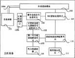
如图8所示为主机设备的结构示意图5,主机设备1包括:主处理板101,设置有CPU处理器,用于信息处理、控制信号的产生以及进行鉴权认证,给家电设备分配地址; As shown in FIG. 8 is a schematic structural diagram 5 of the host device. The
数字总线信号处理单元106,与主处理板101通过计算机总线接口连接,用于对数字总线信号内容进行分析处理,仿真逻辑端口和电平变化等信息,逻辑端口和地址进行关联,将这些信息告知所述主处理板;与图5中所述数字总线信号处理单元功能相同; The digital bus
MAC层帧处理单元107,与数字总线信号处理单元106连接,主要用来区分数字总线信号帧和以太网帧,并对它们作分流; The MAC layer
通信连接选择配置单元108,与MAC层帧处理单元107连接,对有线信号和无线信号进行选择通信;The communication connection selection and
第一电力线调制解调单元103,与通信连接选择配置单元108相连,用于转换电力线信号和数字总线信号,传送控制信号; The first power line modulation and
第一电力线滤波器104,与第一电力线调制解调单元103相连,用于将对电力信号进行滤波、耦合,输出电源以及输出PLC载波信号; The first
外部通信模块105,与主处理板101和MAC层帧处理单元107通过计算机总线连接,用于对信息进行协议转换,与外部通信网络进行通信。 The
在图8所示的结构示意图中,还可以增加一计算机总线与逻辑信号适配单元102,与主处理板101通过数字总线接口如以无线USB方式承载的无线接口连接,同时也和第一电力线调制解调单元103相互传递信号,用于进行数字总线信号如USB信号和逻辑信号的转换,缓存转换后的USB信号以及信号译码;此单元完成数字总线信号与逻辑信号的转换功能。对于简单家电设备的控制,可以经由此单元完成信号译码。也还可以增加一微型基站单元109,与所述通信连接选择配置单元相连,用于利用无线信号与家电通信。微型基站单元109可以为WLAN无线上网的AP,也可以为无线USB信号的收发装置,也可以是红外、蓝牙等其他无线通信方式的收发装置。计算机总线与逻辑信号适配单元102和微型基站单元109也可以同时增加在图8所示的结构图中。在图5所示的主机设备结构示意图上,也可以设置有电视信号处理单元108,与主处理板101连接;电视信号控制及选频单元109,与主处理板101和电视信号处理单元108连接,用于接收电视信号,并进行电视信号的控制及频道的选择。具体描述如图7所述,在此不赘述。在主机设备中如图9所示为主机设备的结构示意图6,还设有:移动通信装置身份识别卡模块111,与主处理板101和外部通信模块105通过PCI总线相连,用于向网络侧提供对主机设备进行身份验证的信息。在主机设备上增加该移动通信装置身份识别卡模块之后,网络侧可以通过对主机设备进行验证,从而达到向验证通过的主机设备进行提供服务。 In the schematic structural diagram shown in Figure 8, a computer bus and logic
在图9所示的主机设备结构示意图增加了移动通信装置身份识别卡模 块111。该移动通信装置身份识别卡模块111也可在上述任一所示的主机设备结构示意图基础上增加,连接关系与图9所示相同,在附图中,省略结构示意图。 A mobile communication device
图5-图9所示的主机设备结构示意图中,硬盘2也是通过PCI总线与主处理板相连接。 In the structural diagrams of the host device shown in FIGS. 5-9 , the
上述MAC层帧处理单元107的内部结构,如图10所示,这个MAC层帧处理单元107包括:MAC层帧控制子单元1070、第一端口1071、第二端口1072以及第三端口1073。第三端口1073与MAC层帧控制子单元1070和通信连接选择配置单元108相连,用于接收从通信连接选择配置单元传输来的数据包,接收到数据包之后,MAC层帧控制子单元1070对该数据包进行分析,分析包头判断以太网帧和非以太网帧,并将它们分别送至不同端口,如是以太网帧,将其送至第一端口1071;第一端口1071与MAC层帧控制子单元1070和外部通信模块通信105,用于将MAC层帧控制子单元送至的以太网帧交给外部通信模块处理105,由其发送至外部网络,或反向处理;如是非以太网帧,将其送至第二端口1072;第二端口1072,与MAC层帧控制子单元1070和数据总线信号处理单元106通信,用于将MAC层帧控制子单元送至的非以大网帧传送给数据总线信号处理单元106进行处理。 The internal structure of the above-mentioned MAC layer
使用这种三端口结构的MAC层帧处理单元107,可以在家庭内部联网中去除了以太网层,简化了协议栈模型;主机设备内相应功能处理单元更加简化,同时通过更底层的包分析判断,使得处理速度更快,包分发能力更强;简化了层结构之后,使得层与层之间的地址映射变得简单,寻址过程更加简化。 Using the MAC layer
用户操作设备4的具体结构图如图11所示,第二PLC滤波器41,与主机设备1的第一PLC滤波器通过电力线连通,用于对电力信号进行滤波,输出电源,输出PLC载波信号;第二电力线(PLC)调制解调单元42,与第二PLC滤波器41相连,用于转换PLC载波信号和数字总线信号如USB信号; 数字总线信号集线器43,与第二PLC调制解调单元42相连,用于提供各种USB接口,对USB信号统一接入和控制。用户操作设备4与主机设备1之间的通信基于数字总线方式如USB信号承载于PLC方式。用户操作设备也可设置为以无线方式承载,即在该设备中除了第二电力线(PLC)调制解调单元42,与第二PLC滤波器41相连,还配置有无线信号收发单元,其与数字总线信号集线器43相连,与主机设备进行信号交互。这样设置的用户操作设备实现了既能与主机设备有线连接也能无线连接。尤其在周围环境发生停电等异常时,可将有线连接方式自动切换到无线连接方式。 The specific structural diagram of the
用户操作设备4与主机设备1是分离设置的,以便于用户操作各种接口和功能单元。用户操作设备4与主机设备1之间的通信基于数字总线方式如USB信号承载于PLC方式。用户操作设备基于数字总线还提供各种接口如图12所示,另一具体结构图,包括:光驱、USB接口、串口、并口、电脑键盘、鼠标、小液晶显示屏、扬声器、耳机麦克插孔、和/或由仿真叉簧、仿真电话手柄、仿真电话机键盘组成的仿真电话机。这些设备可以都是基于USB接口的。 The
用户操作设备4包括用户需操作的各种接口和功能单元,包括:光驱、USB接口、串口、并口、键盘、鼠标、小液晶显示屏、扬声器、耳机麦克插孔、仿真电话机和/或由USB仿真叉簧、USB仿真电话手柄、USB仿真电话机键盘组成的仿真电话机。 The
为便于用户操作,在本数字家庭网关子系统中,用户操作设备与主机设备是分离设置的。用户操作设备上的各种接口和功能单元统一采用数字总线接口如USB总线接口到主机设备上的主处理板。用户操作设备4与主机设备1的主处理板101之间的数字总线信号如USB总线信号,由第二PLC调制解调单元42将信号调制到供电线路上传送给用户操作设备4。 For the convenience of user operation, in this digital home gateway subsystem, the user operation device and the host device are set separately. Various interfaces and functional units on the user operating device uniformly use a digital bus interface such as a USB bus interface to the main processing board on the host device. The digital bus signal between the
在图1-图12所示的家庭网关子系统中主机设备在系统中起到核心控制的作用,为数字家庭提供通用计算资源和通信网关枢纽功能。对于家庭外部 网络,主机设备是数字家庭的网络接入点。对于家庭内部的所有信息家电,主机设备是主控计算机,也即:家庭内部的所有信息家电都是主机设备基于数字总线如USB总线或者1394总线或者其他总线方式的计算机外部设备。对于家庭网关子系统自身,除了电视机(用作主机设备的显示器)之外,其他所有设备,包括用户操作设备和遥控器,都是主机设备基于数字总线如USB总线的计算机外部设备。因此,将家庭内网和家庭外部的通信网络如IP接入网相隔离,所有的家庭内部的信息家电或者可接收无线信号的无线家电设备对外部网络来说是不可见的,家庭网关子系统保证了家庭内部的安全性。 In the home gateway subsystem shown in Figure 1-Figure 12, the host device plays the role of core control in the system, providing general computing resources and communication gateway hub functions for the digital home. For networks outside the home, the host device is the network access point for the digital home. For all information appliances in the home, the host device is the main control computer, that is, all the information appliances in the home are computer peripheral devices based on a digital bus such as USB bus or 1394 bus or other bus methods. For the home gateway subsystem itself, except for the TV (display used as the host device), all other devices, including user operating devices and remote controls, are computer peripherals of the host device based on a digital bus such as a USB bus. Therefore, the home intranet is isolated from the communication network outside the home, such as the IP access network, and all information appliances inside the home or wireless home appliances that can receive wireless signals are invisible to the outside network. The home gateway subsystem Guaranteed the security of the home. the
本发明提出的家庭网关子系统采用模块化结构,组成子系统的各个设备可分布式放置,由一台主机设备、一台电视机、一台用户操作设备、一个或多个遥控器组成。 The home gateway subsystem proposed by the present invention adopts a modular structure, and each device constituting the subsystem can be placed in a distributed manner, and is composed of a host device, a TV set, a user operating device, and one or more remote controllers. the
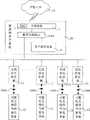
如图13所示,为本发明数字家庭系统实施例一的结构示意图,数字家庭系统100由家庭网关子系统20以及多个无线信号收发器11构成,家庭网关子系统12,与通过IP接入网10接入外部通信网络用于提供各种控制信号;所述家庭网关子系统12包括:主机设备1,设置有硬盘2,用于将外部网络接入家庭内部,以及基于数字总线方式如USB总线方式对家庭内部进行控制;用户操作设备4,通过数字总线方式与所述主机设备进行通信,提供各种用户操作接口和控制单元;该数字总线方式如USB信号承载于PLC或者无线接口上;多个无线信号收发器11,与所述家庭网关子系统主机设备1相连,用于收发PLC载波信号和收发无线信号,并完成PLC载波信号和无线信号的双向转换。图12所示的家庭网关子系统,是采用了PLC进行信号传送,这种家庭网关子系统只要通过电源接口接到电源插座就行。当电源插座出现异常情况,如出现松动,没有接通电源时,该家庭网关子系统可以使用自己的备用电池。即在主机设备1上设置有第一电池及电源模块3,在用户操作设备4设置有第二电池及电源模块5,通过这两个备用电源模块,可以使得家庭网关子系统一直处于接通状态,避免出现异常问题。As shown in FIG. 13 , it is a schematic structural diagram of
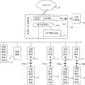
如图14所示数字家庭系统实施例二,在数字家庭系统10,多个可接收无线信号的家电设备12,通过无线信号接口1006如USB接口与所述无线信号收发器11相连;如图15所示数字家庭系统实施例三,还可包括:信息家电13,用于通过供电线路与主机设备进行数字总线信号通信;也可以包括多个可接收无线信号的家电设备12直接通过数据总线接口与主机设备相连,此时数据总线接口是主机设备中的微型基站单元提供的接口形式,可以是无线USB收发装置;如图16所示数字家庭系统实施例四,还可包括上网计算机14,通过电脑上网接口1007与所述主机设备1相连。实施例四是在实施例3的基础上增加了上网计算机14,该上网计算机也可在实施例一和实施例二的基础上增加,其连接关系与实施四中的相同,在附图中,省略结构示意图。如图17所示数字家庭系统实施例五,还包括:远程控制器15,通过移动IP1008接入IP接入网,用于通过IP接入网和主机设备远程控制各种家电设备。 As shown in Figure 14, the second embodiment of the digital home system, in the
可接收无线信号的家电设备具有无线信号处理单元,用来接收无线控制信号,在这种可接收无线信号的家电设备接收到无线控制信号后,家电设备核心处理单元根据该无线控制信号进行对家电设备的控制。如无线空调、冰箱、微波炉、热水器等。 Household electrical appliances capable of receiving wireless signals have a wireless signal processing unit for receiving wireless control signals. After such household electrical appliances capable of receiving wireless signals receive the wireless control signals, the core processing unit of the household electrical appliances performs control of the household appliances according to the wireless control signals. Device control. Such as wireless air conditioners, refrigerators, microwave ovens, water heaters, etc. the
此处,信息家电是相对于可接收无线信号的家电说的,即不采用无线方式通信的家电,如直接连CABLE的电视机,接电力线的电灯开关等。 Here, information home appliances refer to home appliances that can receive wireless signals, that is, home appliances that do not use wireless communication, such as TVs directly connected to CABLEs, light switches connected to power lines, and so on. the
若上述可接收无线信号的家电没有配置无线功能,也可采用电力线信号传输。 If the above-mentioned home appliances capable of receiving wireless signals are not equipped with wireless functions, power line signal transmission may also be used. the
在该数字家庭系统中,家庭网关子系统的结构图,如图1-图12所示,在此不再赘述。利用该数字家庭系统用户通过家庭网关子系统中的遥控器,通过无线接口将控制信息发送给主机设备,主机设备将该无线控制信号转换成电力线信号,找到信息家电对其进行控制。数字家庭系统中,也有各种可接收无线信号的家电设备,这些家电设备通过安装在房间、车库或者庭院中 的无线信号收发器,将无线信号发送给这些无线信号收发器,或者通过无线信号收发器接收从主机设备中无线信号处理单元发出的无线信号,对这些家电设备进行控制,控制信号可以直接是遥控器发送给主机设备的主板处理器,该主板处理器对发送来的各种控制信号进行分析判断,然后将控制信号通过无线信号处理单元处理后发送给家电设备进行控制。用户也可以通过移动通信装置如手机对数字家庭系统中的家电进行控制,通过主处理板以及无线信号处理单元、第一电力线调制解调单元和电力线滤波器的作用,将该控制信号发送给家庭内部的家电。在该数字家庭系统中,主机设备接入网络服务器时,网络服务器对其移动通信装置识别模块进行身份识别,移动通信装置识别模块中存放有身份识别信息,验证该主机设备是否有权接入。 In the digital home system, the structural diagrams of the home gateway subsystem are shown in Fig. 1- Fig. 12 , which will not be repeated here. Using the digital home system, the user sends the control information to the host device through the wireless interface through the remote controller in the home gateway subsystem, and the host device converts the wireless control signal into a power line signal, and finds the information appliance to control it. In the digital home system, there are also various home appliances that can receive wireless signals. These home appliances send wireless signals to these wireless signal transceivers through wireless signal transceivers installed in rooms, garages or courtyards, or send and receive signals through wireless signals. The receiver receives the wireless signal sent by the wireless signal processing unit in the host device, and controls these home appliances. The control signal can be directly sent by the remote control to the main board processor of the host device, and the main board processor can control the various control signals sent. Analyze and judge, and then send the control signal to the home appliance for control after being processed by the wireless signal processing unit. Users can also control the home appliances in the digital home system through mobile communication devices such as mobile phones, and send the control signal to the home through the functions of the main processing board, wireless signal processing unit, first power line modulation and demodulation unit and power line filter. Appliances inside. In the digital home system, when the host device accesses the network server, the network server performs identity recognition on its mobile communication device identification module, and the identification information is stored in the mobile communication device identification module to verify whether the host device has the right to access. the
同时,在数字家庭系统中,电视机可以作为公知电视机使用,直接播放有线电视节目,或者电视机作为家庭网关子系统的一个显示设备,通过用户操作设备提供的键盘、鼠标、光驱、音箱等,而电视机则可以作为主机设备显示器,这样便实现了一个分离设置的电脑,便于用户使用。例如,可以将用户操作设备设置在沙发的附近,在该用户操作设备上用户控制键盘和鼠标,而沙发对面放置电视机作为主机设备的显示装置,用户可以很方便的在沙发上通过键盘和鼠标对网关系统进行控制,而不必考虑布线上的问题,如果采用传统的方式,键盘、鼠标和显示器的连接线不易部署,会受到距离及家庭中其他设备的限制。 At the same time, in the digital home system, the TV can be used as a known TV to directly play cable TV programs, or the TV can be used as a display device of the home gateway subsystem, and the keyboard, mouse, CD-ROM drive, sound box, etc. , and the TV set can be used as a host device display, so that a separate computer is realized, which is convenient for users to use. For example, the user operating device can be set near the sofa, on which the user controls the keyboard and mouse, and a TV is placed opposite the sofa as the display device of the host device, and the user can conveniently use the keyboard and mouse on the sofa. Control the gateway system without having to consider the wiring problem. If the traditional method is used, the connecting lines of the keyboard, mouse and monitor are not easy to deploy, and will be limited by distance and other devices in the home. the
在该数字家庭系统中,由于由电视信号控制及选频单元、电视信号处理单元、和主处理板所提供的电视信号处理功能共同组成,具有类似机顶盒功能,因此,通过家庭网关子系统主机设备就能够进行电视节目的收看。 In this digital home system, since it is composed of the TV signal control and frequency selection unit, the TV signal processing unit, and the TV signal processing function provided by the main processing board, it has the function similar to a set-top box. Therefore, through the home gateway subsystem host device You can watch TV programs. the
在该数字家庭系统中,用户使用计算机上网,可以将计算机接到家庭网关子系统的电脑上网接口登录网络。 In the digital home system, a user uses a computer to access the Internet, and can connect the computer to the computer Internet interface of the home gateway subsystem to log in to the network. the
在本发明数字家庭系统的组网去除了以太网的结构,采用最简单便利的布网方式:以家庭最常见的电力线为主要承载线路,数字总线信号如USB信 号直接适配到电力线上;各房间和车库、庭院等范围内都设有无线信号收发器,近距离内设备可直接采用无线信号通信;通过电力线与无线信号收发器的连接,延长了无线无线信号的通信距离。 In the networking of the digital home system of the present invention, the Ethernet structure is removed, and the simplest and most convenient network layout method is adopted: the most common power line in the family is used as the main carrying line, and digital bus signals such as USB signals are directly adapted to the power line; There are wireless signal transceivers in each room, garage, courtyard, etc., and the equipment within a short distance can directly use wireless signal communication; through the connection between the power line and the wireless signal transceiver, the communication distance of wireless wireless signals is extended. the
在本发明中,数字总线信号可考虑采用USB信号或者1394信号或者其他的总线方式。 In the present invention, the digital bus signal may adopt USB signal or 1394 signal or other bus ways. the
最后所应说明的是,以上实施例仅用以说明本发明的技术方案而非限制,尽管参照较佳实施例对本发明进行了详细说明,本领域的普通技术人员应当理解,可以对本发明的技术方案进行修改或者等同替换,而不脱离本发明技术方案的精神和范围。Finally, it should be noted that the above embodiments are only used to illustrate the technical solutions of the present invention without limitation. Although the present invention has been described in detail with reference to the preferred embodiments, those of ordinary skill in the art should understand that the technical solutions of the present invention can be The scheme shall be modified or equivalently replaced without departing from the spirit and scope of the technical scheme of the present invention.
Claims (48)
Translated fromChinesePriority Applications (4)
| Application Number | Priority Date | Filing Date | Title |
|---|---|---|---|
| CN2007100996421ACN101312422B (en) | 2007-05-25 | 2007-05-25 | A bus-based home gateway subsystem and digital home system |
| PCT/CN2008/070384WO2008145030A1 (en) | 2007-05-25 | 2008-02-29 | Home gateway subsystem and digital home system based on bus |
| JP2010509661AJP4792538B2 (en) | 2007-05-25 | 2008-02-29 | Home gateway subsystem and digital home system based on bus system |
| US12/601,685US8335223B2 (en) | 2007-05-25 | 2008-02-29 | Household gateway subsystem and digital household system based on bus |
Applications Claiming Priority (1)
| Application Number | Priority Date | Filing Date | Title |
|---|---|---|---|
| CN2007100996421ACN101312422B (en) | 2007-05-25 | 2007-05-25 | A bus-based home gateway subsystem and digital home system |
Publications (2)
| Publication Number | Publication Date |
|---|---|
| CN101312422A CN101312422A (en) | 2008-11-26 |
| CN101312422Btrue CN101312422B (en) | 2013-01-30 |
Family
ID=40074571
Family Applications (1)
| Application Number | Title | Priority Date | Filing Date |
|---|---|---|---|
| CN2007100996421AActiveCN101312422B (en) | 2007-05-25 | 2007-05-25 | A bus-based home gateway subsystem and digital home system |
Country Status (4)
| Country | Link |
|---|---|
| US (1) | US8335223B2 (en) |
| JP (1) | JP4792538B2 (en) |
| CN (1) | CN101312422B (en) |
| WO (1) | WO2008145030A1 (en) |
Families Citing this family (25)
| Publication number | Priority date | Publication date | Assignee | Title |
|---|---|---|---|---|
| CN102171676A (en)* | 2008-10-03 | 2011-08-31 | 惠普开发有限公司 | EUI based remote database for dynamic device control |
| DE102009033477A1 (en)* | 2009-07-16 | 2011-01-20 | Rudolf Lonski | Data transmission device for household machines, functional component and household machine |
| CN102104555B (en)* | 2009-12-22 | 2012-12-12 | 华为终端有限公司 | Method for accessing USB equipment of home gateway, home gateway and terminal |
| CN101815159A (en)* | 2009-12-31 | 2010-08-25 | 深圳创维-Rgb电子有限公司 | Intelligent household TV control system |
| CN102387315B (en)* | 2010-09-06 | 2014-09-17 | 广州飒特红外股份有限公司 | Rotary-type infrared thermograph of core module |
| KR20120032644A (en)* | 2010-09-29 | 2012-04-06 | 주식회사 팬택 | Mobile terminal and control method using the same |
| CN102185743A (en)* | 2011-03-24 | 2011-09-14 | 东莞中山大学研究院 | A Digital Home Network System Based on Intelligent Gateway |
| CN102325065A (en)* | 2011-07-14 | 2012-01-18 | 中山爱科数字家庭产业孵化基地有限公司 | A dual-channel digital home control and interaction system and its implementation method |
| CN102291259B (en)* | 2011-08-10 | 2013-09-11 | 天津大学 | Low-voltage power line communication network layer management method based on multi-master station mode |
| TW201325114A (en)* | 2011-12-02 | 2013-06-16 | Ind Tech Res Inst | Wireless control device and method |
| EP2922285A4 (en)* | 2012-11-13 | 2016-07-13 | Shenzhen Itoo Wyrestorm Technology Ltd | Smart home access device |
| CN103841459B (en)* | 2012-11-26 | 2017-12-22 | 鸿富锦精密工业(深圳)有限公司 | Control the system and method for multiple TV set |
| CN104680764A (en)* | 2013-11-29 | 2015-06-03 | 德合南京智能技术有限公司 | Power carrier module capable of accessing domestic appliance to internet of things |
| DE102014104657A1 (en)* | 2014-04-02 | 2015-10-08 | Eaton Electrical Ip Gmbh & Co. Kg | Display device with a wireless interface and an interface to a bus system of a networked control system |
| CN104144119B (en)* | 2014-06-23 | 2018-03-20 | 深圳市同洲电子股份有限公司 | A kind of home gateway |
| RU2678649C2 (en)* | 2014-07-24 | 2019-01-30 | Бтичино С.П.А. | Electronic system for transmitting digital signals according to internet protocols for home automation systems |
| CN105812274B (en)* | 2014-12-30 | 2020-04-21 | 华为技术有限公司 | A business data processing method and related equipment |
| CN105915461A (en)* | 2016-07-01 | 2016-08-31 | 合肥天馈信息技术有限公司 | Multifunctional router |
| CN110794971B (en)* | 2018-12-31 | 2023-06-02 | 北京安天网络安全技术有限公司 | Remote control equipment and system |
| DE102019200907A1 (en)* | 2019-01-24 | 2020-07-30 | Robert Bosch Gmbh | Subscriber station for a bus system and method for data transmission in a bus system |
| CN110365562B (en)* | 2019-08-29 | 2021-12-31 | 青岛东软载波科技股份有限公司 | Smart home interaction terminal with gateway function based on HPLC communication |
| US11540354B2 (en) | 2019-09-30 | 2022-12-27 | Resolution Products, Llc | Gateway with backup power and communications system |
| CN113703346B (en)* | 2020-05-21 | 2023-03-14 | 北京机械设备研究所 | Vehicle control system based on low-voltage power line carrier communication |
| CN116418621B (en)* | 2022-01-05 | 2024-06-25 | 佛山市顺德区美的电子科技有限公司 | Multi-split system and communication method thereof |
| CN117118239B (en)* | 2023-07-06 | 2025-05-06 | 北京交通大学 | Soft switch design and control method suitable for multiport DC/DC converter |
Citations (4)
| Publication number | Priority date | Publication date | Assignee | Title |
|---|---|---|---|---|
| CN2586306Y (en)* | 2002-09-09 | 2003-11-12 | 中国科学院软件研究所 | Family gate |
| EP1427142A1 (en)* | 2002-11-27 | 2004-06-09 | Thomson Licensing S.A. | Home network gateway device |
| CN1848826A (en)* | 2006-04-30 | 2006-10-18 | 中国移动通信集团公司 | Home Gateway Device |
| CN1929526A (en)* | 2006-10-16 | 2007-03-14 | 李大东 | Digital household system |
Family Cites Families (8)
| Publication number | Priority date | Publication date | Assignee | Title |
|---|---|---|---|---|
| DE10083867T1 (en) | 1999-11-16 | 2002-03-07 | Gen Electric | Home network using power line carrier communications |
| US7257328B2 (en)* | 1999-12-13 | 2007-08-14 | Finisar Corporation | System and method for transmitting data on return path of a cable television system |
| JP2002077274A (en)* | 2000-08-31 | 2002-03-15 | Toshiba Corp | Home gateway device, access server device and communication method |
| JP2003085059A (en)* | 2001-03-16 | 2003-03-20 | Matsushita Electric Ind Co Ltd | Firewall setting method and device |
| JP4100074B2 (en)* | 2002-07-10 | 2008-06-11 | 松下電器産業株式会社 | AC adapter integrated power line coupler |
| US7451479B2 (en)* | 2005-02-28 | 2008-11-11 | Zyxel Communications Corporation | Network apparatus with secure IPSec mechanism and method for operating the same |
| US7675897B2 (en)* | 2005-09-06 | 2010-03-09 | Current Technologies, Llc | Power line communications system with differentiated data services |
| CN1777057A (en) | 2005-12-07 | 2006-05-24 | 广东美的电器股份有限公司 | Power line carrier network home appliance and its control method |
- 2007
- 2007-05-25CNCN2007100996421Apatent/CN101312422B/enactiveActive
- 2008
- 2008-02-29USUS12/601,685patent/US8335223B2/enactiveActive
- 2008-02-29WOPCT/CN2008/070384patent/WO2008145030A1/enactiveApplication Filing
- 2008-02-29JPJP2010509661Apatent/JP4792538B2/enactiveActive
Patent Citations (4)
| Publication number | Priority date | Publication date | Assignee | Title |
|---|---|---|---|---|
| CN2586306Y (en)* | 2002-09-09 | 2003-11-12 | 中国科学院软件研究所 | Family gate |
| EP1427142A1 (en)* | 2002-11-27 | 2004-06-09 | Thomson Licensing S.A. | Home network gateway device |
| CN1848826A (en)* | 2006-04-30 | 2006-10-18 | 中国移动通信集团公司 | Home Gateway Device |
| CN1929526A (en)* | 2006-10-16 | 2007-03-14 | 李大东 | Digital household system |
Also Published As
| Publication number | Publication date |
|---|---|
| JP2010528540A (en) | 2010-08-19 |
| US20100172362A1 (en) | 2010-07-08 |
| WO2008145030A1 (en) | 2008-12-04 |
| JP4792538B2 (en) | 2011-10-12 |
| US8335223B2 (en) | 2012-12-18 |
| CN101312422A (en) | 2008-11-26 |
Similar Documents
| Publication | Publication Date | Title |
|---|---|---|
| CN101312422B (en) | A bus-based home gateway subsystem and digital home system | |
| CN100438517C (en) | Family gateway equipment | |
| CN201341181Y (en) | IPTV set-top box with home gateway function | |
| CN101951333B (en) | Digital home intelligent terminal control system | |
| CN101984654A (en) | System, method and terminal for interacting interactive data | |
| CN101883206A (en) | A set-top box with wireless gateway function | |
| CN108259978B (en) | A wired monitor with a wireless router | |
| CN101047671A (en) | Home gateway control system | |
| CN103888349A (en) | Home gateway device with power line communication function | |
| EP2922285A1 (en) | Smart home access device | |
| CN102147566A (en) | Multimedia projector with embedded operation system | |
| CN105591755A (en) | Intelligent home system and authentication connection method on the basis of sound wave authentication connection | |
| TW201445928A (en) | Gateway device for heterogeneous wireless network integrated transmission | |
| CN103873560A (en) | System for controlling household appliance through network | |
| CN203775353U (en) | Embedded type multifunctional wireless liquid crystal display | |
| CN204334852U (en) | A broadcast HDTV access device based on USB video transmission | |
| CN201947292U (en) | Home network system | |
| CN202737896U (en) | Home multimedia network system | |
| CN205320088U (en) | Intelligent home gateway | |
| CN201332483Y (en) | System capable of achieving connection between computer and television through TV box and PC box | |
| CN202008574U (en) | Multi-media projector with embedded operating system | |
| CN207589154U (en) | A Network Audio Management Matrix System | |
| CN103067762A (en) | Television with wireless relay function | |
| CN204795080U (en) | Spectral analysis network "Residential gateway" | |
| CN104010205B (en) | A kind of integrated EOC and WIFI function are in the bi-directional set-top box of one |
Legal Events
| Date | Code | Title | Description |
|---|---|---|---|
| C06 | Publication | ||
| PB01 | Publication | ||
| C10 | Entry into substantive examination | ||
| SE01 | Entry into force of request for substantive examination | ||
| C14 | Grant of patent or utility model | ||
| GR01 | Patent grant |