CN101306653A - A traction power supply device and control method based on PWM rectifier - Google Patents
A traction power supply device and control method based on PWM rectifierDownload PDFInfo
- Publication number
- CN101306653A CN101306653ACNA2008101035290ACN200810103529ACN101306653ACN 101306653 ACN101306653 ACN 101306653ACN A2008101035290 ACNA2008101035290 ACN A2008101035290ACN 200810103529 ACN200810103529 ACN 200810103529ACN 101306653 ACN101306653 ACN 101306653A
- Authority
- CN
- China
- Prior art keywords
- voltage
- power supply
- pwm rectifier
- rectifier
- supply device
- Prior art date
- Legal status (The legal status is an assumption and is not a legal conclusion. Google has not performed a legal analysis and makes no representation as to the accuracy of the status listed.)
- Granted
Links
- 238000000034methodMethods0.000titleclaimsabstractdescription15
- 239000013307optical fiberSubstances0.000claimsabstractdescription12
- 239000003990capacitorSubstances0.000claimsdescription25
- 230000003750conditioning effectEffects0.000claimsdescription12
- 230000001360synchronised effectEffects0.000claimsdescription12
- 238000001514detection methodMethods0.000claimsdescription11
- 238000005070samplingMethods0.000claimsdescription3
- 238000012937correctionMethods0.000claimsdescription2
- 239000003822epoxy resinSubstances0.000claimsdescription2
- 229920000647polyepoxidePolymers0.000claimsdescription2
- 238000003745diagnosisMethods0.000abstract1
- 238000004364calculation methodMethods0.000description4
- 238000010586diagramMethods0.000description3
- 238000001914filtrationMethods0.000description3
- 241001103870AdiaSpecies0.000description2
- 230000009286beneficial effectEffects0.000description2
- 230000000903blocking effectEffects0.000description2
- 238000013500data storageMethods0.000description2
- 239000000835fiberSubstances0.000description2
- 230000006870functionEffects0.000description2
- 238000012360testing methodMethods0.000description2
- 230000009466transformationEffects0.000description2
- 230000008901benefitEffects0.000description1
- 230000008859changeEffects0.000description1
- 238000006243chemical reactionMethods0.000description1
- 230000000694effectsEffects0.000description1
- 230000001939inductive effectEffects0.000description1
- 238000009434installationMethods0.000description1
- 230000010354integrationEffects0.000description1
- 230000003993interactionEffects0.000description1
- 238000002955isolationMethods0.000description1
- 238000012806monitoring deviceMethods0.000description1
- 238000012544monitoring processMethods0.000description1
- 230000003071parasitic effectEffects0.000description1
- 230000008569processEffects0.000description1
- 238000012545processingMethods0.000description1
- 230000001681protective effectEffects0.000description1
- 230000009467reductionEffects0.000description1
- 238000010125resin castingMethods0.000description1
- 230000004044responseEffects0.000description1
- 230000000630rising effectEffects0.000description1
- 230000001131transforming effectEffects0.000description1
- 239000002699waste materialSubstances0.000description1
Images


Landscapes
- Rectifiers (AREA)
Abstract
Translated fromChinese
Description
Translated fromChinese技术领域technical field
本发明属于轨道交通牵引供电领域,具体涉及一种基于PWM整流器的牵引供电装置及控制方法。The invention belongs to the field of rail transit traction power supply, and in particular relates to a traction power supply device and a control method based on a PWM rectifier.
背景技术Background technique
城市轨道交通是关系国计民生的重要行业,牵引供电为城市轨道交通提供电能,是这个领域的一个至关重要的环节。目前,城市轨道交通主要采用750V和1500V直流供电制式。一般采用12脉波或24脉波二极管整流,这种二极管整流器沿用至今已经有几十年历史,它的最大优点是装置结构简单、性能可靠,但是它也存在着直流电压不可控、电压波动大、对交流电网的谐波污染大的问题。此外,由于城轨车辆需要频繁的起动和制动,而在车辆快速启动时,需要的牵引功率大,由二极管整流输出的直流电压会迅速跌落;在车辆制动时,为了防止直流电压升高超过限制值,只能用电阻将制动能量消耗掉,造成能量的极大浪费。因此研制一种直流电压稳定、谐波污染小,并能够将制动能量反馈回交流电网的牵引供电装置具有重要意义。Urban rail transit is an important industry related to the national economy and the people's livelihood, and traction power supply to provide electric energy for urban rail transit is a vital link in this field. At present, urban rail transit mainly adopts 750V and 1500V DC power supply systems. Generally, 12-pulse or 24-pulse diodes are used for rectification. This kind of diode rectifier has been used for decades. Its biggest advantage is that the device has a simple structure and reliable performance, but it also has uncontrollable DC voltage and large voltage fluctuations. , The problem of large harmonic pollution to the AC power grid. In addition, because urban rail vehicles need frequent starting and braking, and when the vehicle starts quickly, the traction power required is large, and the DC voltage rectified by the diode will drop rapidly; when the vehicle is braking, in order to prevent the DC voltage from rising If the limit value is exceeded, the braking energy can only be consumed by a resistor, resulting in a great waste of energy. Therefore, it is of great significance to develop a traction power supply device with stable DC voltage, low harmonic pollution, and the ability to feed back braking energy to the AC grid.
发明内容Contents of the invention
本发明提出一种基于PWM整流器(电压型)的牵引供电装置及控制方法,目的是为城市轨道交通车辆提供一种直流电压稳定,能够反馈制动能量,对交流电网谐波污染小,可靠性高的牵引供电电源,最大限度的实现节能减排。The present invention proposes a traction power supply device and control method based on a PWM rectifier (voltage type), the purpose of which is to provide a stable DC voltage for urban rail transit vehicles, which can feed back braking energy, has little harmonic pollution to the AC grid, and is reliable High traction power supply to maximize energy saving and emission reduction.
本发明的技术方案如下:Technical scheme of the present invention is as follows:
一种基于PWM整流器的牵引供电装置,它由变压器、PWM整流器、控制板、上位机、开关电源五大部分组成。变压器的一次侧接交流电网,二次侧接PWM整流器的输入端,PWM整流器输出接直流接触网;整流器采用PWM整流器的功率开关管采用高集成度的智能功率模块,控制板中采用CPLD进行故障判断和脉冲封锁,并通过光纤接口传输6路PWM脉冲,驱动PWM整流器中功率开关管工作。A traction power supply device based on a PWM rectifier, which is composed of five parts: a transformer, a PWM rectifier, a control board, a host computer, and a switching power supply. The primary side of the transformer is connected to the AC power grid, the secondary side is connected to the input terminal of the PWM rectifier, and the output of the PWM rectifier is connected to the DC contact network; Judgment and pulse blockade, and transmit 6 PWM pulses through the optical fiber interface to drive the power switch tube in the PWM rectifier to work.
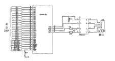
所述的PWM整流器包括:交流电感、交流滤波电容器、智能功率模块、熔断器、直流滤波电容器、A、B相电压传感器、直流电压传感器和直流电流传感器。构成PWM整流器的器件间的连接:The PWM rectifier includes: an AC inductor, an AC filter capacitor, an intelligent power module, a fuse, a DC filter capacitor, A and B phase voltage sensors, a DC voltage sensor and a DC current sensor. Connections between the devices that make up the PWM rectifier:
在变压器副边A和B相上分别接A相电压传感器和B相电压传感器;变压器副边接交流滤波电容,同时接交流滤波电感的一端,交流滤波电感的另一端分别接到三个智能功率模块的中点,三个智能功率模块的顶端并到一起接熔断器的一端,熔断器另一端接直流侧滤波电容的正端,正端上安装直流电流传感器三个智能功率模块的底端也并到一起接到直流支撑电容器的负端N;在正端和负端N之间连接直流电压传感器;交流电感、交流滤波电容器和电网侧变压器的漏感构成一个不对称T型滤波器。Connect the A-phase voltage sensor and the B-phase voltage sensor to the transformer secondary side A and B phase respectively; the transformer secondary side is connected to the AC filter capacitor, and at the same time connect to one end of the AC filter inductor, and the other end of the AC filter inductor is respectively connected to three smart power At the midpoint of the module, the tops of the three intelligent power modules are connected together to one end of the fuse, and the other end of the fuse is connected to the positive end of the filter capacitor on the DC side, and a DC current sensor is installed on the positive end. The bottom ends of the three intelligent power modules are also And connected together to the negative terminal N of the DC support capacitor; a DC voltage sensor is connected between the positive terminal and the negative terminal N; the AC inductance, the AC filter capacitor and the leakage inductance of the grid side transformer form an asymmetrical T-shaped filter.
所述的控制板包括:调理电路、故障检测电路、DSP、CPLD、存储器、光纤接口电路和以太网接口电路。具体连接关系为:调理电路输入与传感器连接,调理电路输出接DSP进行采样,同时接故障检测电路,故障检测电路输出接CPLD;DSP的PWM口接到CPLD,并经过CPLD接到光纤接口电路;此外,DSP与存储器通过I2C总线相连;DSP的数据线、地址线和读写信号线接以太网接口电路。The control board includes: conditioning circuit, fault detection circuit, DSP, CPLD, memory, optical fiber interface circuit and Ethernet interface circuit. The specific connection relationship is: the input of the conditioning circuit is connected to the sensor, the output of the conditioning circuit is connected to the DSP for sampling, and at the same time connected to the fault detection circuit, the output of the fault detection circuit is connected to the CPLD; the PWM port of the DSP is connected to the CPLD, and then connected to the optical fiber interface circuit through the CPLD; In addition, the DSP is connected to the memory through the I2C bus; the data line, address line and read-write signal line of the DSP are connected to the Ethernet interface circuit.
一种基于PWM整流器的牵引供电装置的控制方法,其该控制方法具体实施步骤为:A control method of a traction power supply device based on a PWM rectifier, the specific implementation steps of the control method are:
(1)检测两相交流电压,利用锁相环得到电网电压同步角;(1) Detect the two-phase AC voltage, and use the phase-locked loop to obtain the synchronization angle of the grid voltage;
(2)利用同步角,将检测的两相交流电流转换到同步旋转d-q坐标系,得到d轴电流和q轴电流;(2) Using the synchronous angle, the detected two-phase AC current is converted to a synchronously rotating d-q coordinate system to obtain the d-axis current and the q-axis current;
(3)将直流电压给定值与实际检测的直流电压相减,并进行PI运算,得到电流环d轴电流的给定值,而q轴电流给定值取0;(3) Subtract the given value of the DC voltage from the actually detected DC voltage, and perform PI calculation to obtain the given value of the d-axis current of the current loop, while the given value of the q-axis current is 0;
(4)将(3)中的d轴电流给定值与(2)中的d轴电流相减,并进行PI运算,得到d轴控制电压;同理,将(3)中的q轴电流给定值与(2)中的q轴电流相减,并进行PI运算,得到q轴控制电压;(4) Subtract the given value of the d-axis current in (3) from the d-axis current in (2), and perform PI calculation to obtain the d-axis control voltage; similarly, the q-axis current in (3) The given value is subtracted from the q-axis current in (2), and the PI operation is performed to obtain the q-axis control voltage;
(5)将(4)中d轴控制电压和q轴控制电压变换到静止坐标系,得到α轴电压和β轴电压;(5) Transforming the d-axis control voltage and the q-axis control voltage in (4) into a stationary coordinate system to obtain the α-axis voltage and the β-axis voltage;
(6)利用α轴电压和β轴电压进行空间电压矢量脉宽调制,得到6路PWM脉冲。(6) Use the α-axis voltage and β-axis voltage to perform space voltage vector pulse width modulation to obtain 6 PWM pulses.
本发明和已有技术相比所具有的有益效果:(1)采用PWM整流器,直流电压稳定、功率因数高、对电网谐波污染小,并且能量可以双向流动,能够将车辆制动能量反馈回交流电网供其它车辆使用,节能效果显著;(2)主电路中功率开关器件采用大功率、高集成度的智能功率模块,避免了多个小功率器件并联带来的电路结构和驱动电路复杂的问题,使主电路结构和驱动电路极大简化,装置可靠性提高;(3)采用CPLD进行故障判断和脉冲封锁,控制系统简化,保护速度快;(4)配备专门的上位机作为人机交互接口,方便对装置进行全面实时监控和故障诊断;(5)采用DSP基于同步旋转坐标系的电压电流双闭环控制方法,保证直流电压稳定、动态响应快。Compared with the prior art, the present invention has beneficial effects: (1) adopting PWM rectifier, the DC voltage is stable, the power factor is high, the harmonic pollution to the power grid is small, and the energy can flow in both directions, and the braking energy of the vehicle can be fed back to the The AC power grid is used by other vehicles, and the energy saving effect is remarkable; (2) The power switch device in the main circuit adopts a high-power, highly integrated intelligent power module, which avoids the complicated circuit structure and drive circuit caused by the parallel connection of multiple low-power devices The main circuit structure and driving circuit are greatly simplified, and the reliability of the device is improved; (3) CPLD is used for fault judgment and pulse blockade, the control system is simplified, and the protection speed is fast; (4) a special upper computer is equipped as a human-computer interaction (5) Adopt DSP-based voltage and current double closed-loop control method based on synchronous rotating coordinate system to ensure stable DC voltage and fast dynamic response.
附图说明Description of drawings
图1为基于PWM整流器的牵引供电装置组成框图Figure 1 is a block diagram of the traction power supply device based on PWM rectifier
图2PWM整流器主电路Figure 2 PWM rectifier main circuit
图3控制板电路Figure 3 control board circuit
图4调理电路Figure 4 conditioning circuit
图5故障检测电路Figure 5 fault detection circuit
图6DSP电路Figure 6 DSP circuit
图7CPLD电路Figure 7 CPLD circuit
图8光纤接口电路Figure 8 Optical Fiber Interface Circuit
图9以太网接口电路Figure 9 Ethernet interface circuit
图10存储器电路Figure 10 memory circuit
图11基于同步旋转坐标系的电压电流双闭环控制原理图Figure 11 Schematic diagram of voltage and current double closed-loop control based on synchronous rotating coordinate system
图12软件锁相环原理图Figure 12 Schematic diagram of software phase-locked loop
具体实施方式Detailed ways
本实施例所述牵引供电装置,直流电压为750V,功率500kW。The traction power supply device described in this embodiment has a DC voltage of 750V and a power of 500kW.
本实施例所述牵引供电装置,如图1所示,该装置由变压器、PWM整流器、控制板、上位机、开关电源五大部分组成。变压器用于隔离和降压,变压器一次侧接交流电网,二次侧接PWM整流器;PWM整流器用于实现AC/DC功率变换,直流输出接到直流接触网,为轨道交通车辆提供直流供电电源;控制板通过检测PWM整流器交流侧电压电流和直流侧电压电流,完成相应的控制,发出6路PWM驱动脉冲,驱动PWM整流器中功率开关管工作,同时实施对装置的保护;上位机与控制板通过以太网双向连接,对装置进行控制,以及显示关键变量波形、进行数据存储和故障报警。The traction power supply device described in this embodiment, as shown in FIG. 1 , is composed of five parts: a transformer, a PWM rectifier, a control board, a host computer, and a switching power supply. The transformer is used for isolation and step-down, the primary side of the transformer is connected to the AC grid, and the secondary side is connected to the PWM rectifier; the PWM rectifier is used to realize AC/DC power conversion, and the DC output is connected to the DC catenary to provide DC power supply for rail transit vehicles; The control board completes the corresponding control by detecting the AC side voltage and current and the DC side voltage and current of the PWM rectifier, sends out 6 PWM drive pulses, drives the power switch tube in the PWM rectifier to work, and implements protection for the device at the same time; the host computer and the control board pass through Ethernet two-way connection, control the device, and display key variable waveforms, data storage and fault alarm.
所述牵引供电装置中开关电源,主要用于为控制板供电,将输入的220V交流变为控制板提供5V、±15V、24V电源,该开关电源输出稳定、纹波小、可靠性高。The switching power supply in the traction power supply device is mainly used to supply power to the control board. The input 220V AC is converted into 5V, ±15V, 24V power supply for the control board. The switching power supply has stable output, small ripple and high reliability.
如图2所示,所述牵引供电装置中PWM整流器包括:交流电感、交流滤波电容器、智能功率模块、熔断器、直流滤波电容器、A、B相电压传感器、直流电压传感器和直流电流传感器。构成PWM整流器的器件间的连接:As shown in Fig. 2, the PWM rectifier in the traction power supply device includes: an AC inductor, an AC filter capacitor, an intelligent power module, a fuse, a DC filter capacitor, A and B phase voltage sensors, a DC voltage sensor and a DC current sensor. Connections between the devices that make up the PWM rectifier:
在变压器副边A和B相上分别接A相电压传感器1和B相电压传感器2;变压器副边接交流滤波电容3,同时接交流滤波电感4的一端,交流滤波电感4的另一端分别接到三个智能功率模块5、6、7的中点,三个智能功率模块的顶端并到一起接熔断器8的一端,熔断器另一端接直流侧滤波电容10的正端P,正端P上安装直流电流传感器9三个智能功率模块的底端也并到一起接到直流支撑电容器C的负端N;在正端P和负端N之间连接直流电压传感器11;交流电感4、交流滤波电容器3和电网侧变压器的漏感构成一个不对称T型滤波器,相对于传统的仅有一个电感L的滤波器,滤波器阶数更高,滤波器整体体积大大减小,主要用于滤除交流电流中的开关频率次谐波电流,减小对电网的谐波污染。Connect A-phase
所述牵引供电装置中变压器采用环氧树脂浇注干式变压器,一次侧输入电压10kV,采用星形连接,便于高压侧接地,二次侧输出电压420V,也采用星形连接,变压器容量500kVA。The transformer in the traction power supply device is an epoxy resin casting dry-type transformer, the primary side input voltage is 10kV, and it adopts star connection, which is convenient for grounding the high voltage side. The secondary side output voltage is 420V, also adopts star connection, and the transformer capacity is 500kVA.
交流滤波电容器3采用无极性电容,星型连接,电容耐压450VAC,容量为150uF。The
智能功率模块5、6、7均采用西门康公司的SKiiP系列智能IGBT功率模块,参数1700V/2400A,型号为:SKiiP 2403GB173D。每个含有上下两个开关管,自带散热器,每个功率模块集成驱动、短路保护、电流传感器、温度传感器,光纤接口。功率模块之间通过无感母排连接,减小寄生参数对主电路的影响。每个模块可以流过数千安培的电流,方便使用、可靠性高。由于智能功率模块内部集成了电流传感器,所以不需要外加交流电流传感器就可得到两相交流电流ia和ib。The
熔断器8采用Ferraz公司750V/1600A快速熔断器,型号为:A75P1600-4。且其安装位置特殊(在功率模块与直流支撑电容之间),使得当功率模块贯穿短路或直流输出短路时都能够起保护作用,防止故障范围扩大。The
直流侧滤波电容10的耐压为1200V,容量为20000uF,由多个400V耐压的电解电容串并联而成或多个薄膜电容并联而成的电容器组,用于滤除直流电压纹波,稳定直流电压。The DC
A、B相电压传感器用于测量两相交流电压Ua和Ub,用于交流过欠压保护,以及软件锁相环。直流电压传感器都采用LEM公司1000V的电压传感器,型号为:AV100-1000;直流电流传感器采用LEM公司1000A的电流传感器,型号为:LT1005-S。The A and B phase voltage sensors are used to measure the two-phase AC voltage Ua and Ub for AC over-voltage and under-voltage protection, and a software phase-locked loop. The DC voltage sensor adopts the 1000V voltage sensor of LEM Company, the model is: AV100-1000; the DC current sensor adopts the 1000A current sensor of LEM Company, the model is LT1005-S.
直流电压传感器11用于测量直流电压Udc,进行闭环控制,稳直流电压。The
直流电流传感器9用于测量直流输出电流Idc,计算供电装置输出功率和直流短路保护。The DC
上位机,其通过以太网与控制板中DSP进行通信和数据交换。该上位机采用工业计算机或便携式笔记本电脑,既能作为固定的系统监控装置,放置在供电站的监控室;也能用于初期的系统调试,记录和显示关键电量的波形,提高调试效率。该上位机中程序使用高级语言编写,实现数据存储、变量显示、谐波分析、电量计算、故障报警功能。The upper computer communicates and exchanges data with the DSP in the control board through Ethernet. The upper computer adopts an industrial computer or a portable notebook computer, which can be used as a fixed system monitoring device and placed in the monitoring room of the power supply station; it can also be used for initial system debugging, recording and displaying key power waveforms, and improving debugging efficiency. The program in the upper computer is written in a high-level language to realize data storage, variable display, harmonic analysis, power calculation, and fault alarm functions.
图3为所述牵引供电装置中控制板电路包括:调理电路、故障检测电路、DSP、CPLD、存储器、光纤接口电路和以太网接口电路。Fig. 3 shows that the control board circuit in the traction power supply device includes: conditioning circuit, fault detection circuit, DSP, CPLD, memory, optical fiber interface circuit and Ethernet interface circuit.
控制板电路见图3至图10,其构成的各器件之间的连接关系如下,:The circuit of the control board is shown in Figure 3 to Figure 10, and the connection relationship between the various components is as follows:
调理电路的输入端口Ua与A相电压传感器1相连,输入端口Ub与B相电压传感器2相连,输入端口Ia和Ib分别接到智能功率模块5和6的电流传感器输出端,输入端口Idc与直流电流传感器9相连,输入端口Udc直流电压传感器11相连,调理电路的输出端口Uai、Ubi、Iai、Ibi、Idci、Udci分别与故障检测电路的输入端口Uai、Ubi、Iai、Ibi、Idci、Udci依次连接,调理电路的输出端口ADUa、ADUb、ADIa、ADIb、ADIdc、ADUdc分别与DSP的输入端口ADUa、ADUb、ADIa、ADIb、ADIdc、ADUdc依次连接;The input port Ua of the conditioning circuit is connected to the
故障检测电路的端口DCOV、DCUV、ACUV、ACOV分别与CPLD的端口DCOV、DCUV、ACUV、ACOV依次连接;The ports DCOV, DCUV, ACUV, and ACOV of the fault detection circuit are respectively connected to the ports DCOV, DCUV, ACUV, and ACOV of the CPLD in sequence;
DSP的端口PWM1、PWM2、PWM3、PWM4、PWM5、PWM6分别与CPLD的端口、PWM1、PWM2、PWM3、PWM4、PWM5、PWM6依次连接;The ports PWM1, PWM2, PWM3, PWM4, PWM5, and PWM6 of the DSP are respectively connected to the ports of the CPLD, PWM1, PWM2, PWM3, PWM4, PWM5, and PWM6 in sequence;
CPLD的端口XPWM1、XPWM2、XPWM3、XPWM4、XPWM5、XPWM6分别与光纤接口电路的端口XPWM1、XPWM2、XPWM3、XPWM4、XPWM5、XPWM6依次连接;纤接口电路的端口与智能功率模块连接;The ports XPWM1, XPWM2, XPWM3, XPWM4, XPWM5, and XPWM6 of the CPLD are respectively connected to the ports XPWM1, XPWM2, XPWM3, XPWM4, XPWM5, and XPWM6 of the fiber interface circuit in sequence; the ports of the fiber interface circuit are connected to the intelligent power module;
DSP的端口ETH__/TEST、ETHBHEn、ETH__RST、ETH__ENn、ETH__IOR、ETH__IOW、XA1、XA2、XA3、XD0至XD15依次与以太网接口电路的端口ETH__/TEST、ETHBHEn、TH__RST、ETH__ENn、ETH__IOR、ETH__IOW、XA1、XA2、XA3、XD1至XD15相连接,DSP的端口SCL、SDA分别与存储器的SCL、SDA连接。The ports ETH__/TEST, ETHBHEn, ETH__RST, ETH__ENn, ETH__IOR, ETH__IOW, XA1, XA2, XA3, XD0 to XD15 of the DSP are sequentially connected with the ports ETH__/TEST, ETHBHEn, TH__RST, ETH__ENn, ETH__IOR, ETH__IOW, XA1, XA2, XA3, XD1 to XD15 are connected, and the ports SCL and SDA of the DSP are respectively connected with the SCL and SDA of the memory.
控制板中,包括RC低通滤波电路和加法电路,用于对来自PWM整流器中各传感器的电压和电流信号进行滤波,滤除高频干扰,并将信号变换到0-3V以内,然后送到DSP进行AD采样,同时也送到故障检测电路。The control board includes an RC low-pass filter circuit and an adding circuit, which are used to filter the voltage and current signals from each sensor in the PWM rectifier, filter out high-frequency interference, and convert the signal to within 0-3V, and then send it to DSP carries on AD sampling, also sends fault detecting circuit at the same time.
故障检测电路由比较器和电阻电容组成,其将来自调理电路的电压电流信号与设定保护值进行比较,并将比较输出的故障信号送到CPLD中;CPLD对所有故障信号进行逻辑处理,如果发生严重故障,立刻封锁脉冲,并给DSP的功率保护中断口PDPINT一个中断信号;DSP发出的PWM脉冲经过CPLD后送到光纤接口电路,再送到各智能功率模块,所以CPLD很容易实现硬件封锁脉冲的功能;所述存储器与DSP通过SPI总线相连,用于永久存储一些重要运行参数和系统信息,掉电不丢失;所述以太网接口电路与DSP通过数据线、地址线,以及少数控制线相连,用于实现与上位机的高速数据交换。The fault detection circuit is composed of a comparator and a resistor and capacitor, which compares the voltage and current signals from the conditioning circuit with the set protection value, and sends the fault signal output from the comparison to the CPLD; the CPLD performs logic processing on all fault signals, if When a serious failure occurs, the pulse is blocked immediately, and an interrupt signal is sent to the power protection interrupt port PDPINT of the DSP; the PWM pulse sent by the DSP is sent to the optical fiber interface circuit after passing through the CPLD, and then sent to each intelligent power module, so the CPLD can easily realize the hardware blocking pulse function; the memory is connected to the DSP through the SPI bus for permanent storage of some important operating parameters and system information, which will not be lost when power is off; the Ethernet interface circuit is connected to the DSP through data lines, address lines, and a small number of control lines , used to realize high-speed data exchange with the host computer.
光纤接口电路由电阻、三极管、接口组成。The optical fiber interface circuit is composed of resistors, transistors and interfaces.
所述DSP采用TI公司的32位高性能数字信号处理器TMS320F2812,时钟频率150M;所述CPLD主要用于逻辑保护和脉冲封锁,采用Ateral公司的EMP3128A;所述以太网接口电路中主要包括一块10M以太网控制芯片,信号CS8900A;所述存储器采用非易失性铁电存储器,掉电后数据不丢失,其采用SPI总线与DSP进行数据交换,型号为:FM24CL64。DSP和CPLD采用同类器件,均能达到本发明的有益效果。Described DSP adopts 32 high-performance digital signal processors TMS320F2812 of TI Company, clock frequency 150M; Described CPLD is mainly used in logical protection and pulse blocking, adopts EMP3128A of Ateral Company; Mainly comprise a 10M in the described Ethernet interface circuit Ethernet control chip, signal CS8900A; the memory adopts non-volatile ferroelectric memory, the data will not be lost after power failure, and it uses SPI bus to exchange data with DSP, the model is: FM24CL64. DSP and CPLD adopt similar devices, and both can achieve the beneficial effects of the present invention.
所述牵引供电装置中上位机采用工业控制计算机,CPU采用双核高性能处理器,保证运算速度;网卡采用100M以太网卡;配置了160G大容量硬盘,用于实时存储供电装置运行数据,以备将来查阅;采用不间断电源(UPS)对上位机供电,确保供电安全。The upper computer in the traction power supply device adopts an industrial control computer, and the CPU adopts a dual-core high-performance processor to ensure the calculation speed; the network card adopts a 100M Ethernet card; a 160G large-capacity hard disk is configured to store the operating data of the power supply device in real time for future use Check; Use an uninterruptible power supply (UPS) to supply power to the host computer to ensure power supply safety.
所述牵引供电装置中开关电源采用多个开关电源模块,提供4路隔离的稳定直流电压,包括1路5V,1路15V,1路-15V,1路24V,总额定功率约100W,输入220V交流电来自UPS。The switching power supply in the traction power supply device adopts multiple switching power supply modules to provide 4 isolated stable DC voltages, including 1 channel of 5V, 1 channel of 15V, 1 channel of -15V, and 1 channel of 24V, with a total rated power of about 100W and an input of 220V The AC power comes from a UPS.
如上所述一种基于PWM整流器的牵引供电装置,其中的PWM整流器控制采用基于同步旋转坐标系的电压电流双闭环控制,如图4所示,其中ia、ib为两相交流电流,ua、ub为两相交流电压。As mentioned above, a traction power supply device based on PWM rectifier, the PWM rectifier control adopts voltage and current double closed-loop control based on synchronous rotating coordinate system, as shown in Figure 4, whereia andib are two-phase AC current, ua andub are two-phase AC voltages.
该控制方法如图11所示,其具体实施步骤为:The control method is shown in Figure 11, and its specific implementation steps are:
(1)检测两相交流电压Ua和Ub,利用锁相环得到电网电压同步角θ。(1) Detect the two-phase AC voltage Ua and Ub , and use the phase-locked loop to obtain the grid voltage synchronization angle θ.
(2)利用同步角θ,将检测的两相交流电流ia和ib转换到同步旋转d-q坐标系,得到d轴电流id和q轴电流iq。(2) Using the synchronous angle θ, the detected two-phase AC currents ia and ib are transformed into a synchronously rotating dq coordinate system to obtain d-axis current id and q-axis current iq .
(3)将直流电压给定值U*dc与实际检测的直流电压Udc相减,并进行PI运算,得到电流环d轴电流的给定值id*,而q轴电流给定值iq*取0。(3) Subtract the given value of DC voltage U*dc from the actual detected DC voltageUdc , and perform PI operation to obtain the given value of d-axis current id* of the current loop, and the given value of q-axis current iq* takes 0.
(4)将(3)中的d轴电流给定值id*与(2)中的d轴电流id相减,并进行PI运算,得到d轴控制电压Vd;同理,将(3)中的q轴电流给定值iq*与(2)中的q轴电流iq相减,并进行PI运算,得到q轴控制电压Uq。(4) Subtract the d-axis current given valueid* in (3) from the d-axis currentid in (2), and perform PI operation to obtain the d-axis control voltage Vd ; similarly, ( Subtract the q-axis current given value iq* in (3) from the q-axis current iq in (2), and perform PI operation to obtain the q-axis control voltage Uq .
(5)将(4)中Ud和Uq变换到静止坐标系,得到Uα和Uβ。(5) Transform Ud and Uq in (4) to the stationary coordinate system to obtain Uα and Uβ .
(6)利用Uα和Uβ进行空间电压矢量脉宽调制(SVPWM),得到6路PWM脉冲。(6) Use Uα and Uβ to perform space voltage vector pulse width modulation (SVPWM) to obtain 6 PWM pulses.
所述的PI控制都采用抗饱和PI调节器。The PI control described above adopts an anti-saturation PI regulator.
电压外环和电流内环的PI控制都采用抗饱和型数字PI调节器。Both the PI control of the voltage outer loop and the current inner loop adopt anti-saturation digital PI regulators.
上述控制方法中,锁相环采用软件锁相环,原理如图12所示,其主要包括坐标变换、滤波、PI调节、积分四个部分。该锁相环工作流程是:利用当前同步角θ将静止坐标系下的两相交流电压Ua、Ub转换到同步旋转坐标系得到Ud、Uq,然后将q轴电压Uq送入滤波环节,滤除电网电压畸变或干扰引入的高频成分后,再与q轴电压给定值0进相减后进行PI调节,PI的输出作为对角频率的修正量Δω,加上工频角频率ω后进行积分,最后得到修正后的同步角θ。只要当前同步角θ经坐标变换得到的电网电压在旋转坐标系下的q轴分量不等于零,就表明当前同步角还未完全与电网电压同步,从而导致PI输出的角频率修正量Δω发生相应变化,并使输出的同步角θ也发生变化,闭环稳定时所得θ角即为所需电网电压同步角。相对于传统依赖过零点检测的硬件锁相环而言,软件锁相环可以简化硬件电路,同时可以借助灵活的软件滤波措施增强对谐波干扰和电压畸变的抑制能力。In the above-mentioned control method, the phase-locked loop adopts a software phase-locked loop, and its principle is shown in Figure 12, which mainly includes four parts: coordinate transformation, filtering, PI adjustment, and integration. The working process of the PLL is: use the current synchronous angle θ to convert the two-phase AC voltage Ua , Ub in the stationary coordinate system to the synchronous rotating coordinate system to obtain Ud , Uq , and then send the q-axis voltage Uq into the In the filtering link, after filtering out the high-frequency components introduced by the grid voltage distortion or interference, the PI adjustment is performed after subtracting the given value of the q-axis voltage from zero. After the angular frequency ω is integrated, the corrected synchronization angle θ is finally obtained. As long as the q-axis component of the grid voltage obtained by the current synchronization angle θ through coordinate transformation is not equal to zero in the rotating coordinate system, it indicates that the current synchronization angle is not completely synchronized with the grid voltage, resulting in a corresponding change in the angular frequency correction Δω of the PI output , and the output synchronous angle θ also changes, and the θ angle obtained when the closed-loop is stable is the required grid voltage synchronous angle. Compared with the traditional hardware phase-locked loop that relies on zero-crossing detection, the software phase-locked loop can simplify the hardware circuit, and at the same time, it can enhance the ability to suppress harmonic interference and voltage distortion with the help of flexible software filtering measures.
Claims (9)
Translated fromChinesePriority Applications (1)
| Application Number | Priority Date | Filing Date | Title |
|---|---|---|---|
| CN2008101035290ACN101306653B (en) | 2008-04-08 | 2008-04-08 | Traction power supply equipment based on PWM rectifier and control method |
Applications Claiming Priority (1)
| Application Number | Priority Date | Filing Date | Title |
|---|---|---|---|
| CN2008101035290ACN101306653B (en) | 2008-04-08 | 2008-04-08 | Traction power supply equipment based on PWM rectifier and control method |
Publications (2)
| Publication Number | Publication Date |
|---|---|
| CN101306653Atrue CN101306653A (en) | 2008-11-19 |
| CN101306653B CN101306653B (en) | 2010-06-30 |
Family
ID=40123401
Family Applications (1)
| Application Number | Title | Priority Date | Filing Date |
|---|---|---|---|
| CN2008101035290AExpired - Fee RelatedCN101306653B (en) | 2008-04-08 | 2008-04-08 | Traction power supply equipment based on PWM rectifier and control method |
Country Status (1)
| Country | Link |
|---|---|
| CN (1) | CN101306653B (en) |
Cited By (17)
| Publication number | Priority date | Publication date | Assignee | Title |
|---|---|---|---|---|
| CN101907868A (en)* | 2010-08-05 | 2010-12-08 | 暨南大学珠海学院 | Intelligent trouble diagnosis method for tractive power supply system and system thereof |
| CN101969195A (en)* | 2010-10-26 | 2011-02-09 | 沈阳工业大学 | Transformer direct current magnetic bias compensation device with reactive power compensation function and control method |
| CN102185505A (en)* | 2011-05-20 | 2011-09-14 | 海华电子企业(中国)有限公司 | Method and system for controlling three-phase high-power-factor PWM (Pulse-Width Modulation) rectifier |
| CN103023057A (en)* | 2012-10-26 | 2013-04-03 | 河南师范大学 | Voltage-type PWM (pulse-width modulation) rectifier output power control method under power grid unsymmetrical fault |
| CN103612574A (en)* | 2013-09-10 | 2014-03-05 | 广州市地下铁道总公司 | Energy-feedback-type traction power supply device based on resonance control strategy |
| CN103703666A (en)* | 2011-05-23 | 2014-04-02 | 雷诺股份公司 | Method for controlling switches of a current rectifier connected to an on-board charger |
| CN104779648A (en)* | 2015-03-26 | 2015-07-15 | 西南交通大学 | Optimizing control of single-phase PWM (Pulse-Width Modulation) rectifiers based on d-q coordinates |
| CN105186890A (en)* | 2015-09-07 | 2015-12-23 | 广州电力机车有限公司 | Transformerless topological structure of AC drive vehicle and method for controlling DC output |
| CN105186891A (en)* | 2015-09-07 | 2015-12-23 | 广州电力机车有限公司 | Algorithm for endowing rectifier module with stable output voltage |
| CN105915098A (en)* | 2016-05-30 | 2016-08-31 | 科德数控股份有限公司 | PWM rectifier device based on software phase-locked loop |
| CN109116752A (en)* | 2018-08-31 | 2019-01-01 | 北京交通大学 | A kind of the dynamic model analogue system and control method of urban track traffic |
| CN110794234A (en)* | 2019-10-31 | 2020-02-14 | 北京交通大学 | PWM converter direct current support capacitor residual life online monitoring system and method |
| CN110880790A (en)* | 2019-12-23 | 2020-03-13 | 太原理工大学 | Control method of grid-connected power converter with LCL topological structure |
| CN110932585A (en)* | 2019-12-10 | 2020-03-27 | 国网河南省电力公司电力科学研究院 | Modulation method and device for reducing ultrahigh harmonic amplitude at converter switching frequency |
| CN112366958A (en)* | 2020-11-17 | 2021-02-12 | 广东川琪科技有限公司 | Adjustable switching power supply |
| CN112532087A (en)* | 2020-11-26 | 2021-03-19 | 北京金自天正智能控制股份有限公司 | Commutation rectification feedback system of switch type power grid and control method thereof |
| CN115461951A (en)* | 2020-04-08 | 2022-12-09 | 三菱电机株式会社 | Direct current distribution system |
- 2008
- 2008-04-08CNCN2008101035290Apatent/CN101306653B/ennot_activeExpired - Fee Related
Cited By (26)
| Publication number | Priority date | Publication date | Assignee | Title |
|---|---|---|---|---|
| CN101907868B (en)* | 2010-08-05 | 2012-01-25 | 暨南大学珠海学院 | Intelligent trouble diagnosis method for tractive power supply system and system thereof |
| CN101907868A (en)* | 2010-08-05 | 2010-12-08 | 暨南大学珠海学院 | Intelligent trouble diagnosis method for tractive power supply system and system thereof |
| CN101969195A (en)* | 2010-10-26 | 2011-02-09 | 沈阳工业大学 | Transformer direct current magnetic bias compensation device with reactive power compensation function and control method |
| CN101969195B (en)* | 2010-10-26 | 2012-12-05 | 沈阳工业大学 | Transformer direct current magnetic bias compensation device with reactive power compensation function and control method |
| CN102185505A (en)* | 2011-05-20 | 2011-09-14 | 海华电子企业(中国)有限公司 | Method and system for controlling three-phase high-power-factor PWM (Pulse-Width Modulation) rectifier |
| CN103703666B (en)* | 2011-05-23 | 2016-10-19 | 雷诺股份公司 | Method for controlling switching of a current rectifier connected to an on-board charger |
| CN103703666A (en)* | 2011-05-23 | 2014-04-02 | 雷诺股份公司 | Method for controlling switches of a current rectifier connected to an on-board charger |
| CN103023057A (en)* | 2012-10-26 | 2013-04-03 | 河南师范大学 | Voltage-type PWM (pulse-width modulation) rectifier output power control method under power grid unsymmetrical fault |
| CN103612574A (en)* | 2013-09-10 | 2014-03-05 | 广州市地下铁道总公司 | Energy-feedback-type traction power supply device based on resonance control strategy |
| CN103612574B (en)* | 2013-09-10 | 2016-10-26 | 广州地铁集团有限公司 | Energy feedback type traction power supply device based on resonance control strategy |
| CN104779648A (en)* | 2015-03-26 | 2015-07-15 | 西南交通大学 | Optimizing control of single-phase PWM (Pulse-Width Modulation) rectifiers based on d-q coordinates |
| CN105186890A (en)* | 2015-09-07 | 2015-12-23 | 广州电力机车有限公司 | Transformerless topological structure of AC drive vehicle and method for controlling DC output |
| CN105186891A (en)* | 2015-09-07 | 2015-12-23 | 广州电力机车有限公司 | Algorithm for endowing rectifier module with stable output voltage |
| CN105186891B (en)* | 2015-09-07 | 2018-08-28 | 广州电力机车有限公司 | A method of it allows rectification module to have and stabilizes the output voltage |
| CN105186890B (en)* | 2015-09-07 | 2018-08-28 | 广州电力机车有限公司 | The method that AC drive vehicle transless controls direct current output |
| CN105915098A (en)* | 2016-05-30 | 2016-08-31 | 科德数控股份有限公司 | PWM rectifier device based on software phase-locked loop |
| CN109116752A (en)* | 2018-08-31 | 2019-01-01 | 北京交通大学 | A kind of the dynamic model analogue system and control method of urban track traffic |
| CN110794234A (en)* | 2019-10-31 | 2020-02-14 | 北京交通大学 | PWM converter direct current support capacitor residual life online monitoring system and method |
| CN110794234B (en)* | 2019-10-31 | 2024-06-11 | 北京交通大学 | On-line monitoring method for residual life of direct-current supporting capacitor of PWM converter |
| CN110932585A (en)* | 2019-12-10 | 2020-03-27 | 国网河南省电力公司电力科学研究院 | Modulation method and device for reducing ultrahigh harmonic amplitude at converter switching frequency |
| CN110880790A (en)* | 2019-12-23 | 2020-03-13 | 太原理工大学 | Control method of grid-connected power converter with LCL topological structure |
| CN110880790B (en)* | 2019-12-23 | 2022-06-21 | 太原理工大学 | Control method of grid-connected power converter with LCL topological structure |
| CN115461951A (en)* | 2020-04-08 | 2022-12-09 | 三菱电机株式会社 | Direct current distribution system |
| CN112366958A (en)* | 2020-11-17 | 2021-02-12 | 广东川琪科技有限公司 | Adjustable switching power supply |
| CN112532087A (en)* | 2020-11-26 | 2021-03-19 | 北京金自天正智能控制股份有限公司 | Commutation rectification feedback system of switch type power grid and control method thereof |
| CN112532087B (en)* | 2020-11-26 | 2022-01-14 | 北京金自天正智能控制股份有限公司 | Commutation rectification feedback system of switch type power grid and control method thereof |
Also Published As
| Publication number | Publication date |
|---|---|
| CN101306653B (en) | 2010-06-30 |
Similar Documents
| Publication | Publication Date | Title |
|---|---|---|
| CN101306653B (en) | Traction power supply equipment based on PWM rectifier and control method | |
| CN201186619Y (en) | Traction power supply equipment based on PWM rectifier | |
| JP2014516507A (en) | Electric vehicle PWM rectifier and inverter transformer pulse charging system | |
| CN102710165B (en) | Improved method for controlling direct current (DC) bus voltage of two-stage converter | |
| CN101882799A (en) | Control method of HVDC converter without AC voltage sensor | |
| CN103050967B (en) | Active disturbance control method of flexible direct current power transmission system | |
| CN204597799U (en) | Based on the three-phase VIENNA rectifier of 60 ° of coordinate systems | |
| CN102222931A (en) | Microgrid three-phase grid-connected inverter system and control method thereof | |
| CN105429179B (en) | The special filtering of pumping unit can present device and control method | |
| CN101969294A (en) | Alternating current servo driver capable of realizing energy feedback | |
| CN104836466A (en) | 60-degree coordinate system-based three-phase VIENNA rectifier and control method | |
| CN106159951B (en) | A kind of composite power source with emergency power supply and active power filtering function | |
| CN105978040B (en) | Variable-frequency variable-voltage power supply intelligence inverse probability control system and control method | |
| CN104269882A (en) | Energy feedback unit and energy feedback method | |
| CN107732900A (en) | A kind of ship connects bank electricity method and system | |
| CN106208141A (en) | A kind of V2G charge and discharge device with no-power compensation function | |
| CN202444277U (en) | Three-phase photovoltaic grid-connected power generation device applicable to distributed power generation | |
| CN205945096U (en) | V2G fills discharge device with reactive compensation function | |
| CN105576687B (en) | A kind of AC/DC energy storage PCU Power Conditioning Unit and its control method | |
| CN105406752A (en) | Control system for I-type and T-type three-level bidirectional PWM (Pulse-Width Modulation) rectifiers | |
| CN103178545B (en) | Power grid current harmonic complementary circuit and control method for photovoltaic grid-connected inverter | |
| CN201860294U (en) | Alternating-current servo driver capable of realizing energy feedback | |
| CN209460370U (en) | A pair-to-drag test platform for squirrel-cage asynchronous motors based on dual-PWM converters operating in four quadrants | |
| CN109873487B (en) | Master-slave backup method for three-phase three-level VIENNA rectifier | |
| CN203911558U (en) | Off-board conductive direct-current electric vehicle charger having APF function |
Legal Events
| Date | Code | Title | Description |
|---|---|---|---|
| C06 | Publication | ||
| PB01 | Publication | ||
| C10 | Entry into substantive examination | ||
| SE01 | Entry into force of request for substantive examination | ||
| C14 | Grant of patent or utility model | ||
| GR01 | Patent grant | ||
| CF01 | Termination of patent right due to non-payment of annual fee | ||
| CF01 | Termination of patent right due to non-payment of annual fee | Granted publication date:20100630 Termination date:20210408 |