Movatterモバイル変換


[0]ホーム

URL:


CN101301185B - Smart Ad Removal Robot - Google Patents

Smart Ad Removal Robot
Download PDF

Info

Publication number
CN101301185B
CN101301185BCN2008100646456ACN200810064645ACN101301185BCN 101301185 BCN101301185 BCN 101301185BCN 2008100646456 ACN2008100646456 ACN 2008100646456ACN 200810064645 ACN200810064645 ACN 200810064645ACN 101301185 BCN101301185 BCN 101301185B
Authority
CN
China
Prior art keywords
ground
metope
round brush
advertisement
car body
Prior art date
Legal status (The legal status is an assumption and is not a legal conclusion. Google has not performed a legal analysis and makes no representation as to the accuracy of the status listed.)
Expired - Fee Related
Application number
CN2008100646456A
Other languages
Chinese (zh)
Other versions
CN101301185A (en
Inventor
曲建俊
孙鹏飞
尉成果
陈定
孙瑛
郝广鑫
周定江
Current Assignee (The listed assignees may be inaccurate. Google has not performed a legal analysis and makes no representation or warranty as to the accuracy of the list.)
Harbin Institute of Technology Shenzhen
Original Assignee
Harbin Institute of Technology Shenzhen
Priority date (The priority date is an assumption and is not a legal conclusion. Google has not performed a legal analysis and makes no representation as to the accuracy of the date listed.)
Filing date
Publication date
Application filed by Harbin Institute of Technology ShenzhenfiledCriticalHarbin Institute of Technology Shenzhen
Priority to CN2008100646456ApriorityCriticalpatent/CN101301185B/en
Publication of CN101301185ApublicationCriticalpatent/CN101301185A/en
Application grantedgrantedCritical
Publication of CN101301185BpublicationCriticalpatent/CN101301185B/en
Expired - Fee Relatedlegal-statusCriticalCurrent
Anticipated expirationlegal-statusCritical

Links

Images

Landscapes

Abstract

An intelligent advertisement removing robot relates to a robot capable of automatically removing the advertisements on the ground and the wall, aiming at the problems of, low work efficiency and high labor intensity in manual removing, and water resource waste and impossibility of recovering crushed advertisement paper in removing advertisement by means of a water torch. A wall roller brush (3), a wall spray head (1), and a wall garbage reclaiming mechanism (4) are fixedly connected with a wall roller brush fixing plate (52), a wall roller brush synchronous-belt transmission mechanism (53) is connected to the wall roller brush (3), a wall roller brush retractable motor (42) is connected with a wall roller brush retractable mechanism (54) which is fixedly connected to the wall roller brush fixing plate (52), a floor nozzle (12) and a floor roller brush (14) are securely connected with a floor roller brush fixing plate (76), a ground advertisement detecting sensor (13), a ground garbage reclaiming mechanism (73), and a lifting mechanism (72) are securely connected to the vehicle body, a floor roller brush synchronous-belt transmission mechanism (77) is connected with the floor roller brush (14), and a floor roller lifting motor (39) is connected with a floor roller brush lifting mechanism (74). The inventive intelligent advertisement removing robot has high work efficiency, and water source and labor can be saved.

Description

Translated fromChinese
智能广告清除机器人Smart Ad Removal Robot

技术领域technical field

本发明涉及一种能够自动清除街上墙面和地面广告的机器人。The invention relates to a robot capable of automatically removing wall and ground advertisements on the street.

背景技术Background technique

在每个城市的大街上四处张贴的广告给环保部门增加了很大的工作量。因为广告纸背面是不干胶,清除特别困难,并且要耗费大量的人力和物力。目前,清除这种广告只有人工和用高压水枪两种方法。前者工作效率很低、劳动强度大、人力资源浪费;后者是采用汽油发动机与高压泵直接组合或者采用电瓶作为能量来源,高压水枪冲刷广告时射流强劲,可在移动中完成车辆、设备、墙面、门窗、地面的清洗保洁。授权公告号为CN 2784097Y、授权公告日为2006年5月31日的实用新型专利,公开了一种《高压清洗机》,但这种高压清洗机所需水量较大,对水资源造成巨大的浪费,同时冲刷后的碎广告纸无法回收,需要清洁工人进一步打扫。The advertisements posted everywhere on the streets of every city have added a lot of work to the environmental protection department. Because the back of the advertising paper is self-adhesive, it is particularly difficult to remove, and it will consume a lot of manpower and material resources. At present, there are only two ways to remove such advertisements: manual and high-pressure water guns. The former has low work efficiency, high labor intensity, and waste of human resources; the latter uses a direct combination of a gasoline engine and a high-pressure pump or uses a battery as an energy source. Cleaning and cleaning of surfaces, doors, windows and floors. The authorized announcement number is CN 2784097Y, and the authorized announcement date is May 31, 2006. A utility model patent discloses a "high-pressure cleaner", but this kind of high-pressure cleaner requires a large amount of water, which causes huge damage to water resources. Waste, at the same time, the shredded advertising paper after washing cannot be recycled, and needs to be further cleaned by cleaners.

发明内容Contents of the invention

本发明的目的是提供一种智能广告清除机器人,以解决采用人工清除广告存在工作效率低、劳动强度大、人力资源浪费的问题以及采用高压水枪清除广告存在水资源浪费严重,且冲刷后的碎广告纸无法回收的问题。The purpose of the present invention is to provide an intelligent advertisement removal robot to solve the problems of low work efficiency, high labor intensity, and waste of human resources in the use of manual removal of advertisements, as well as the serious waste of water resources in the removal of advertisements by high-pressure water guns, and the broken pieces after washing The problem that advertising paper cannot be recycled.

本发明为解决上述技术问题采用的技术方案是:所述广告清除机器人包括水泵、电磁阀;所述广告清除机器人还包括墙面广告清除装置和地面广告清除装置;所述墙面广告清除装置包括一组墙面喷头、多个墙面广告探测传感器、墙面滚刷、墙面垃圾回收机构、墙面滚刷固定板、墙面滚刷电机、墙面滚刷同步带传动机构、墙面滚刷伸缩电机和墙面滚刷伸缩机构;所述地面广告清除装置包括升降机构、车体、两个后驱动轮、两个前万向轮、一组地面喷头、多个地面广告探测传感器、地面滚刷、地面垃圾回收机构、地面滚刷升降机构、地面滚刷电机、地面滚刷升降电机、两个驱动电机、两个后驱动轮联轴器、电瓶、地面滚刷固定板、地面滚刷同步带传动机构、地面滚刷联轴器和微控制器;所述墙面滚刷、一组墙面喷头和多个墙面广告探测传感器由下至上依次设置,多个墙面广告探测传感器设置在同一竖直面内,所述墙面垃圾回收机构设置在墙面滚刷的下面,墙面滚刷、一组墙面喷头和墙面垃圾回收机构均与墙面滚刷固定板的左侧面固接,多个墙面广告探测传感器固装在滑动车体上端的左侧面上,所述墙面滚刷电机与墙面滚刷固定板的右侧面固接,墙面滚刷电机的动力输出轴通过墙面滚刷同步带传动机构与墙面滚刷传动连接,所述墙面滚刷伸缩电机与墙面滚刷伸缩机构传动连接,墙面滚刷伸缩电机与滑动车体固接,所述墙面滚刷伸缩机构与墙面滚刷固定板的右侧面和滑动车体固接,所述车体由滑动车体和固定车体组成;所述升降机构由定滑轮、双向绞盘、第一钢丝绳、第二钢丝绳、蜗轮蜗杆减速器和整体提升电机组成;所述滑动车体的下端装在固定车体的滑道内且与固定车体滑动配合,所述定滑轮与固定车体上端的左侧面固接,蜗轮蜗杆减速器固装在固定车体下端的左侧面上,蜗轮蜗杆减速器的动力输入轴与整体提升电机的动力输出轴传动连接,蜗轮蜗杆减速器的动力输出轴上固装有双向绞盘,所述整体提升电机与固定车体固接,所述第一钢丝绳的一端与滑动车体固接,第一钢丝绳的另一端绕过定滑轮缠绕在双向绞盘上,所述第二钢丝绳的一端与滑动车体固接,第二钢丝绳的另一端缠绕在双向绞盘上,第一钢丝绳与第二钢丝绳在双向绞盘上的缠绕方向相反,所述两个后驱动轮分别设置在固定车体后面的左侧和右侧,每个后驱动轮分别通过相应的后驱动轮联轴器与驱动电机的动力输出轴传动连接,所述两个驱动电机固装在固定车体后端的上端面上,所述两个前万向轮分别固装在固定车体左前下侧面和右前下侧面上,所述一组地面喷头和多个地面广告探测传感器均沿地面滚刷的轴向方向布置,多个地面广告探测传感器、一组地面喷头及地面滚刷依次由前至后设置,多个地面广告探测传感器设置在同一水平面内,一组地面喷头和地面滚刷均与地面滚刷固定板的下端面固接,多个地面广告探测传感器与固定车体前端的底端面固接,所述地面垃圾回收机构固装在地面滚刷后面的固定车体上和地面滚刷固定板上,所述地面滚刷电机与地面滚刷固定板固接,地面滚刷电机的动力输出轴通过地面滚刷联轴器及地面滚刷同步带传动机构与地面滚刷传动连接,所述地面滚刷升降电机与地面滚刷升降机构传动连接,地面滚刷升降电机与固定车体固接,所述地面滚刷升降机构与地面滚刷固定板和固定车体固接,所述电瓶、水泵和微控制器均固装在固定车体上,电瓶的七个供电输出端分别与墙面滚刷电机、墙面滚刷伸缩电机、地面滚刷电机、地面滚刷升降电机、整体提升电机及两个后驱动电机的电源输入端连接,微控制器的七个电机输出端分别连接在墙面滚刷电机、墙面滚刷伸缩电机、地面滚刷电机、地面滚刷升降电机、整体提升电机及两个驱动电机的开停控制装置上,微控制器的两个传感器信号输入端分别与墙面广告探测传感器的信号输出端和多个地面广告探测传感器的信号输出端连接,所述水泵的出口端通过电磁阀分别与一组墙面喷头和一组地面喷头连接。The technical solution adopted by the present invention to solve the above technical problems is: the advertisement removal robot includes a water pump and a solenoid valve; the advertisement removal robot also includes a wall advertisement removal device and a ground advertisement removal device; the wall advertisement removal device includes A set of wall nozzles, multiple wall advertising detection sensors, wall roller brush, wall garbage recycling mechanism, wall roller brush fixing plate, wall roller brush motor, wall roller brush synchronous belt transmission mechanism, wall roller Brush telescopic motor and wall rolling brush telescopic mechanism; The ground advertisement removal device includes a lifting mechanism, a car body, two rear drive wheels, two front universal wheels, a group of ground nozzles, a plurality of ground advertisement detection sensors, a ground Roller brush, floor garbage recovery mechanism, floor roller brush lifting mechanism, floor roller brush motor, floor roller brush lift motor, two driving motors, two rear drive wheel couplings, battery, floor roller brush fixing plate, floor roller brush Synchronous belt drive mechanism, ground roller brush coupling and microcontroller; the wall roller brush, a group of wall nozzles and a plurality of wall advertisement detection sensors are arranged sequentially from bottom to top, and a plurality of wall advertisement detection sensors are arranged In the same vertical plane, the wall garbage recovery mechanism is arranged under the wall roller brush, and the wall roller brush, a group of wall nozzles and the wall garbage recovery mechanism are all connected to the left side of the wall roller brush fixing plate. The surface is fixed, and a plurality of wall advertising detection sensors are fixed on the left side of the upper end of the sliding car body. The wall rolling brush motor is fixed on the right side of the wall rolling brush fixing plate, and the wall rolling brush motor The power output shaft of the wall brush is connected to the wall brush through the synchronous belt transmission mechanism of the wall brush. The telescopic motor of the wall brush is connected to the telescopic mechanism of the wall brush. Then, the telescoping mechanism of the wall surface rolling brush is fixedly connected with the right side of the wall surface rolling brush fixing plate and the sliding car body, and the described car body is composed of a sliding car body and a fixed car body; the lifting mechanism is composed of a fixed pulley, Two-way winch, first wire rope, second wire rope, worm gear reducer and integral lifting motor; The left side of the upper end of the car body is fixed, and the worm gear reducer is fixed on the left side of the lower end of the fixed car body. The power input shaft of the worm gear reducer is connected with the power output shaft of the integral lifting motor. A two-way winch is fixed on the power output shaft of the power output shaft, the integral hoisting motor is fixedly connected to the fixed car body, one end of the first steel wire rope is fixedly connected to the sliding car body, and the other end of the first steel wire rope is wound around the fixed pulley in a two-way On the winch, one end of the second steel wire rope is fixedly connected to the sliding car body, the other end of the second steel wire rope is wound on the two-way winch, the winding direction of the first steel wire rope and the second steel wire rope on the two-way winch is opposite, and the two rear The driving wheels are respectively arranged on the left side and the right side behind the fixed car body, and each rear driving wheel is respectively connected with the power output shaft of the driving motor through a corresponding rear driving wheel coupling, and the two driving motors are fixed on the On the upper end surface of the rear end of the fixed car body, the two front universal wheels are respectively fixed on the left front lower side and the right front lower side of the fixed car body. The ground advertisement detection sensors are all arranged along the axial direction of the ground roller brush. Multiple ground advertisement detection sensors, a group of ground nozzles and the ground roller brush are arranged in sequence from front to back. Multiple ground advertisement detection sensors are arranged in the same horizontal plane. A set of ground nozzles and ground roller brushes are fixedly connected to the lower end surface of the ground roller brush fixing plate, a plurality of ground advertising detection sensors are fixedly connected to the bottom end surface of the front end of the fixed car body, and the ground garbage recovery mechanism is fixedly installed behind the ground roller brush On the fixed car body and the ground roller brush fixing plate, the ground roller brush motor is fixedly connected to the ground roller brush fixing plate, and the power output shaft of the ground roller brush motor is driven by the ground roller brush coupling and the ground roller brush synchronous belt The mechanism is connected with the ground roller brush transmission, the ground roller brush lifting motor is connected with the ground roller brush lifting mechanism, the ground roller brush lifting motor is fixedly connected with the fixed vehicle body, and the ground roller brush lifting mechanism is connected with the ground roller brush fixing plate and the ground roller brush lifting mechanism. The fixed vehicle body is fixedly connected, and the battery, water pump and microcontroller are all fixedly installed on the fixed vehicle body. The seven power supply output terminals of the battery are respectively connected with the wall roller brush motor, the wall roller brush telescopic motor, and the ground roller brush motor. , the ground roller brush lift motor, the overall lifting motor and the power input terminals of the two rear drive motors are connected, and the seven motor output terminals of the microcontroller are respectively connected to the wall roller brush motor, the wall roller brush telescopic motor, the floor roller brush On the motor, the ground roller brush lifting motor, the overall lifting motor and the start-stop control device of the two driving motors, the two sensor signal input terminals of the microcontroller are respectively connected with the signal output terminals of the wall advertisement detection sensor and multiple ground advertisement detection sensors. The signal output end of the sensor is connected, and the outlet end of the water pump is respectively connected with a group of wall nozzles and a group of ground nozzles through electromagnetic valves.

本发明的有益效果是:(1)能够通过墙面广告探测传感器和地面广告探测传感器自动识别墙面广告和地面广告,具有很高的智能性。(2)可以在很短的时间内将广告擦除,具有很高的效率。(3)在清除广告时只需喷出少量水雾,在很大程度上节省了水资源。(4)本发明是全自动机器人,在擦广告的过程中无需人的干预,节省了人的劳动力。The beneficial effects of the present invention are: (1) The wall advertisement and the ground advertisement can be automatically identified by the wall advertisement detection sensor and the ground advertisement detection sensor, which has high intelligence. (2) Advertisements can be erased in a short period of time, with high efficiency. (3) Only a small amount of water mist needs to be sprayed when removing advertisements, which saves water resources to a large extent. (4) The present invention is a fully automatic robot, which saves human labor without human intervention in the process of wiping advertisements.

附图说明Description of drawings

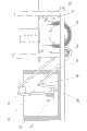
图1是本发明的整体结构主视图,图2是图1的左视图,图3是图1的俯视图,图4是地面滚刷升降机构74的左视图,图5是墙面滚刷伸缩机构54的主视图,图6是地面垃圾回收机构73与固定车体70装配在一起的主视图,图7是升降机构72与车体8装配在一起的主视图,图8是环形擦布带25的展开示意图,图9是墙面滚刷3和地面滚刷14的刷毛采用普通排列方式的示意图,图10是墙面滚刷3和地面滚刷14的刷毛采用螺旋线排列方式的示意图,图11是墙面滚刷3和地面滚刷14的刷毛采用“人字形”螺旋线排列方式的示意图,图12是墙面广告探测传感器2阵列方式示意图,图13是地面广告探测传感器13阵列方式示意图。Fig. 1 is a front view of the overall structure of the present invention, Fig. 2 is a left view of Fig. 1, Fig. 3 is a top view of Fig. 1, Fig. 4 is a left view of the ground rollingbrush lifting mechanism 74, and Fig. 5 is a wall rolling brushtelescopic mechanism 54 front view, Fig. 6 is the front view of the groundgarbage recovery mechanism 73 assembled with thefixed car body 70, Fig. 7 is the front view of thelifting mechanism 72 assembled with thecar body 8, Fig. 8 is the endless wiper belt 25 Figure 9 is a schematic diagram of the common arrangement of the bristles of thewall brush 3 and thefloor brush 14, and Figure 10 is a schematic diagram of the spiral arrangement of thewall brush 3 and thefloor brush 14. 11 is a schematic diagram showing that the bristles of thewall roller brush 3 and theground roller brush 14 are arranged in a "herringbone" helix, FIG. 12 is a schematic diagram of the array of walladvertising detection sensors 2, and FIG. 13 is a schematic diagram of the array of groundadvertising detection sensors 13 .

具体实施方式Detailed ways

具体实施方式一:结合图1~图7和图9~图13说明本实施方式,本实施方式的广告清除机器人包括水泵50、电磁阀51、墙面广告清除装置和地面广告清除装置;所述墙面广告清除装置包括一组墙面喷头1、多个墙面广告探测传感器2、墙面滚刷3、墙面垃圾回收机构4、墙面滚刷固定板52、墙面滚刷电机40、墙面滚刷同步带传动机构53、墙面滚刷伸缩电机42和墙面滚刷伸缩机构54;所述地面广告清除装置包括升降机构72、车体8、两个后驱动轮10、两个前万向轮11、一组地面喷头12、多个地面广告探测传感器13、地面滚刷14、地面垃圾回收机构73、地面滚刷升降机构74、地面滚刷电机37、地面滚刷升降电机39、两个驱动电机45、两个后驱动轮联轴器75、电瓶48、地面滚刷固定板76、地面滚刷同步带传动机构77、地面滚刷联轴器79和微控制器80;所述墙面滚刷3、一组墙面喷头1和多个墙面广告探测传感器2由下至上依次设置,多个墙面广告探测传感器2设置在同一竖直面内,所述墙面垃圾回收机构4设置在墙面滚刷3的下面,墙面滚刷3、一组墙面喷头1和墙面垃圾回收机构4均与墙面滚刷固定板52的左侧面固接,多个墙面广告探测传感器2固装在滑动车体71上端的左侧面上,所述墙面滚刷电机40与墙面滚刷固定板52的右侧面固接,墙面滚刷电机40的动力输出轴通过墙面滚刷同步带传动机构53与墙面滚刷3传动连接,所述墙面滚刷伸缩电机42与墙面滚刷伸缩机构54传动连接,墙面滚刷伸缩电机42与滑动车体71固接,所述墙面滚刷提升机构54与墙面滚刷固定板52的右侧面和滑动车体71固接,所述车体8由滑动车体71和固定车体70组成;所述升降机构72由定滑轮6、双向绞盘9、第一钢丝绳36、第二钢丝绳78、蜗轮蜗杆减速器43和整体提升电机44组成;所述滑动车体71的下端装在固定车体70的滑道内且与固定车体70滑动配合,所述定滑轮6与固定车体70上端的左侧面固接,蜗轮蜗杆减速器43固装在固定车体70下端的左侧面上,蜗轮蜗杆减速器43的动力输入轴与整体提升电机44的动力输出轴传动连接,蜗轮蜗杆减速器43的动力输出轴上固装有双向绞盘9,所述整体提升电机44与固定车体70固接,所述第一钢丝绳36的一端与滑动车体71固接,第一钢丝绳36的另一端绕过定滑轮6缠绕在双向绞盘9上,所述第二钢丝绳78的一端与滑动车体71固接,第二钢丝绳78的另一端缠绕在双向绞盘9上,第一钢丝绳36与第二钢丝绳78在双向绞盘9上的缠绕方向相反,所述两个后驱动轮10分别设置在固定车体70后面的左侧和右侧,每个后驱动轮10分别通过相应的后驱动轮联轴器75与驱动电机45的动力输出轴传动连接,所述两个驱动电机45固装在固定车体70后端的上端面上,所述两个前万向轮11分别固装在固定车体70左前下侧面和右前下侧面上,所述一组地面喷头12和多个地面广告探测传感器13均沿地面滚刷14的轴向方向布置,多个地面广告探测传感器13、一组地面喷头12及地面滚刷14依次由前至后设置,多个地面广告探测传感器13设置在同一水平面内,一组地面喷头12和地面滚刷14均与地面滚刷固定板76的下端面固接,多个地面广告探测传感器13与固定车体70前端的底端面固接,所述地面垃圾回收机构73固装在地面滚刷14后面的固定车体70上和地面滚刷固定板76上,所述地面滚刷电机37与地面滚刷固定板76固接,地面滚刷电机37的动力输出轴通过地面滚刷联轴器79及地面滚刷同步带传动机构77与地面滚刷14传动连接,所述地面滚刷升降电机39与地面滚刷升降机构74传动连接,地面滚刷升降电机39与固定车体70固接,所述地面滚刷升降机构74与地面滚刷固定板76和固定车体70固接,所述电瓶48、水泵50和微控制器80均固装在固定车体70上,电瓶48的七个供电输出端分别与墙面滚刷电机40、墙面滚刷伸缩电机42、地面滚刷电机37、地面滚刷升降电机39、整体提升电机44及两个驱动电机45的电源输入端连接,微控制器80的七个电机输出端分别连接在墙面滚刷电机40、墙面滚刷伸缩电机42、地面滚刷电机37、地面滚刷升降电机39、整体提升电机44及两个驱动电机45的开停控制装置上,微控制器80的两个传感器信号输入端分别与墙面广告探测传感器2的信号输出端和多个地面广告探测传感器1 3的信号输出端连接,所述水泵50的出口端通过电磁阀5 1分别与一组墙面喷头1和一组地面喷头12连接。所述墙面滚刷3和地面滚刷14均为圆柱型滚筒刷,采用尼龙材料制成,刷毛采用普通、螺旋线或者“人字形”螺旋线的排列方式。其中,按“人字形”螺旋线排列方式的滚刷(墙面滚刷3和地面滚刷14)有利于消除滚刷所受到的轴向力,便于垃圾的回收。Specific Embodiment 1: This embodiment is described in conjunction with FIGS. 1 to 7 and FIGS. 9 to 13. The advertisement removal robot in this embodiment includes awater pump 50, asolenoid valve 51, a wall advertisement removal device and a ground advertisement removal device; The wall advertisement removal device includes a group of wall nozzles 1, a plurality of walladvertisement detection sensors 2, awall roller brush 3, a wallgarbage recovery mechanism 4, a wall rollerbrush fixing plate 52, a wallroller brush motor 40, Wall surface rolling brush synchronousbelt drive mechanism 53, wall surface rolling brush telescopic motor 42 and wall surface rolling brushtelescopic mechanism 54; Described ground advertisement clearing device compriseslifting mechanism 72,car body 8, tworear driving wheels 10, two Frontuniversal wheel 11, a group offloor nozzles 12, multiple flooradvertising detection sensors 13,floor roller brush 14, floorgarbage recovery mechanism 73, floor rollerbrush lifting mechanism 74, floorroller brush motor 37, floor rollerbrush lift motor 39 , twodriving motors 45, two reardrive wheel couplings 75,battery 48, ground rollingbrush fixing plate 76, ground rolling brush synchronousbelt transmission mechanism 77, groundrolling brush coupling 79 andmicrocontroller 80; Thewall roller brush 3, a group of wall nozzles 1 and a plurality of walladvertisement detection sensors 2 are sequentially arranged from bottom to top, and a plurality of walladvertisement detection sensors 2 are arranged in the same vertical plane, and the wall garbage is recovered Themechanism 4 is arranged under thewall roller brush 3, thewall roller brush 3, a group of wall nozzles 1 and the wallgarbage recovery mechanism 4 are all fixedly connected to the left side of the wall rollerbrush fixing plate 52, and multiple wall Surfaceadvertisement detecting sensor 2 is fixedly installed on the left side of slidingcar body 71 upper ends, and described wall surfacerolling brush motor 40 is fixedly connected with the right side of wall surface rollingbrush fixing plate 52, and the power of wall surfacerolling brush motor 40 The output shaft is connected with thewall roller brush 3 through the synchronousbelt transmission mechanism 53 of the wall surface roller brush.Car body 71 is affixed, and described wall surface rollingbrush lifting mechanism 54 is fixedly connected with the right side of wall surface rollingbrush fixing plate 52 and slidingcar body 71, and describedcar body 8 is formed by slidingcar body 71 and fixedcar body 70. composition; thelifting mechanism 72 is made up of afixed pulley 6, a two-way winch 9, afirst wire rope 36, asecond wire rope 78, aworm gear reducer 43 and anintegral lifting motor 44; the lower end of thesliding car body 71 is mounted on a fixed car In the slideway of thefixed car body 70 and slidingly matched with thefixed car body 70, thefixed pulley 6 is fixedly connected to the left side of the upper end of thefixed car body 70, and theworm gear reducer 43 is fixed on the left side of the lower end of thefixed car body 70 , the power input shaft of theworm gear reducer 43 is connected with the power output shaft of theintegral lifting motor 44, and the power output shaft of theworm gear reducer 43 is fixedly equipped with a two-way capstan 9, and theintegral lifting motor 44 is connected to thefixed car body 70 Fixed connection, one end of the firststeel wire rope 36 is fixedly connected with thesliding car body 71, the other end of the firststeel wire rope 36 is wound around the fixedpulley 6 on the two-way winch 9, and one end of the secondsteel wire rope 78 is connected with thesliding car body 71 is fixedly connected, and the other end of the secondsteel wire rope 78 is wound on the two-way capstan 9, and the first steel wire Therope 36 is opposite to the winding direction of thesecond wire rope 78 on the two-way winch 9. The tworear drive wheels 10 are respectively arranged on the left and right sides behind thefixed vehicle body 70, and eachrear drive wheel 10 passes through the corresponding The reardriving wheel coupling 75 is connected to the power output shaft of thedriving motor 45. The twodriving motors 45 are fixed on the upper end surface of the rear end of thefixed car body 70. The two frontuniversal wheels 11 are fixed respectively. On the left front lower side and the right front lower side of thefixed car body 70, the group ofground sprinklers 12 and a plurality of groundadvertisement detection sensors 13 are arranged along the axial direction of theground roller brush 14, and a plurality of groundadvertisement detection sensors 13, a A group ofground nozzles 12 andground roller brushes 14 are arranged from front to back in turn, and a plurality of groundadvertisement detection sensors 13 are arranged in the same horizontal plane. Affixed connection, a plurality of groundadvertising detection sensors 13 are affixed to the bottom surface of the front end of thefixed car body 70, and the groundgarbage recovery mechanism 73 is fixed on thefixed car body 70 behind theground roller brush 14 and the ground rollerbrush fixing plate 76 Above, the ground rollingbrush motor 37 is fixedly connected to the ground rollingbrush fixing plate 76, and the power output shaft of the ground rollingbrush motor 37 is connected to theground rolling brush 14 through the ground rollingbrush coupling 79 and the ground rolling brush synchronousbelt transmission mechanism 77. Transmission connection, the ground rollingbrush lifting motor 39 is in transmission connection with the ground rollingbrush lifting mechanism 74, the ground rollingbrush lifting motor 39 is fixedly connected with thefixed car body 70, and the ground rollingbrush lifting mechanism 74 is connected with the ground rollingbrush fixing plate 76 It is fixedly connected with thefixed car body 70, and thestorage battery 48, thewater pump 50 and themicrocontroller 80 are all fixedly installed on thefixed car body 70. Brush retractable motor 42, groundrolling brush motor 37, ground rollingbrush lifting motor 39,integral lifting motor 44 and the power supply input end of twodriving motors 45 are connected, and seven motor output ends of micro-controller 80 are respectively connected on the wall rolling. On the start-stop control device ofbrush motor 40, wall rolling brush telescopic motor 42, groundrolling brush motor 37, ground rollingbrush lifting motor 39,integral lifting motor 44 and twodrive motors 45, two sensors ofmicrocontroller 80 The signal input end is respectively connected with the signal output end of the walladvertisement detection sensor 2 and the signal output end of a plurality of groundadvertisement detection sensors 13, and the outlet end of thewater pump 50 is respectively connected with a group of wall surface nozzles 1 through thesolenoid valve 51. Connect with one group ofground nozzles 12. Thewall roller brush 3 and thefloor roller brush 14 are all cylindrical roller brushes, made of nylon material, and the bristles are arranged in a common, helical or "herringbone" helix. Wherein, the roller brushes (wallsurface roller brushes 3 and ground roller brushes 14) arranged in a "herringbone" helical pattern are conducive to eliminating the suffered axial force of the roller brushes, and are convenient for recycling of garbage.

采用传感器自动识别广告,利用滚刷将广告快速擦除,并能自动收集地面和墙面广告垃圾。后轮驱动电机45采用伺服电机,两后轮单独驱动,行走灵活,通过闭环控制的方式使机器人能够精确定位。通过电磁阀51可实现水泵50向地面喷头12和墙面喷头1的切换。喷头可将水喷成水雾状,将滚刷润湿,从而间接地将小广告喷湿。整体提升电机44选择普通的直流电机,但在不供电时不能自锁,利用蜗轮蜗杆减速器43可以使墙面滚刷固定板52停在任意一个位置。由于双向绞盘9上缠绕着两根旋向相反的钢丝,当双向绞盘9转动时,分别释放和卷入钢丝,在墙面滚刷伸缩滑道5的导向作用下,实现墙面滚刷固定板52的上升或下降。当墙面滚刷3刷墙面广告时,墙面滚刷固定板52受到向上的力。第二钢丝绳78可以防止墙面滚刷固定板52和滑动车体71晃动,水泵50的入水口安装过滤网。本实施方式中的所有电机和传感器均为外购件。Use sensors to automatically identify advertisements, use the roller brush to quickly erase advertisements, and automatically collect advertising waste on the ground and walls. The rearwheel drive motor 45 adopts a servo motor, and the two rear wheels are driven independently, and the walking is flexible, and the robot can be accurately positioned by the closed-loop control mode. The switching of thewater pump 50 to theground spray head 12 and the wall spray head 1 can be realized through thesolenoid valve 51 . The nozzle can spray water into water mist to wet the roller brush, thereby indirectly spraying the small advertisement.Integral lifting motor 44 selects common DC motor, but can not self-lock when not supplying power, utilizeworm gear reducer 43 to make wall surface rolling brush fixedplate 52 stop at any position. Because the two-way capstan 9 is wound with two opposite steel wires, when the two-way capstan 9 rotates, the steel wires are respectively released and drawn in, and under the guidance of the wall roller brush telescopic slideway 5, the wall roller brush fixing plate is realized. 52 up or down. When thewall roller brush 3 brushes the wall advertisement, the wall rollerbrush fixing plate 52 is subject to upward force. Thesecond wire rope 78 can prevent the wall surface rolling brush fixedplate 52 and thesliding car body 71 from rocking, and the water inlet of thewater pump 50 is equipped with a filter screen. All motors and sensors in this embodiment are purchased parts.

具体实施方式二:结合图1、图2和图6说明本实施方式,本实施方式的地面垃圾回收机构73由水箱17、刷子21、从动辊22、上挤压辊23、下挤压辊81、主动辊24、环形擦布带25和擦地辊33组成;所述主动辊24和从动辊22设置在同一纵垂面上,主动辊24与水箱17的上端面转动连接,从动辊22装在水箱17内且与水箱17的侧壁转动连接,上挤压辊23和下挤压辊81上下正对设置,上挤压辊23和下挤压辊81与主动辊24和从动辊22不在同一纵垂面内,上挤压辊23和下挤压辊81位于主动辊24和从动辊22之间,上挤压辊23和下挤压辊81均与水箱17的侧壁转动连接,所述擦地辊33设置在水箱17与地面滚刷14之间,且擦地辊33位于从动辊22的下方,擦地辊33与地面滚刷固定板76固接,所述环形擦布带25套装在主动辊24、从动辊22和擦地辊33上并位于上挤压辊23和下挤压辊8 1之间,所述刷子21固装在水箱1 7内,刷子21位于下挤压辊81和从动辊22之间,刷子21与环形擦布带25相接触。所述主动辊24由电机带动,从动辊22置于水中,通过两个挤压辊可将环形擦布带25上多余的水挤掉。擦地辊33和地面滚刷14同时升降,防止在不工作的情况下环形擦布带25过度磨损。地面垃圾回收机构73也可以利用吸尘器原理,将垃圾通过负压吸到垃圾桶中。其它组成及连接关系与具体实施方式一相同。Specific embodiment two: this embodiment is described in conjunction with Fig. 1, Fig. 2 and Fig. 6, and the groundgarbage recovery mechanism 73 of this embodiment is composed ofwater tank 17,brush 21, driven roller 22,upper squeeze roller 23,lower squeeze roller 81. Driving roller 24, ring-shaped cloth wiping belt 25 and ground-wiping roller 33 are composed; said driving roller 24 and driven roller 22 are arranged on the same vertical plane, and driving roller 24 is connected in rotation with the upper end surface ofwater tank 17, driven Roller 22 is contained in thewater tank 17 and is connected with the sidewall rotation ofwater tank 17, andupper squeezing roller 23 andlower squeezing roller 81 are arranged up and down, andupper squeezing roller 23 andlower squeezing roller 81 and driving roller 24 and follower The driven roll 22 is not in the same vertical plane, and theupper squeeze roll 23 and thelower squeeze roll 81 are located between the driving roll 24 and the driven roll 22, and theupper squeeze roll 23 and thelower squeeze roll 81 are all connected to the side of thewater tank 17. The wall is rotatably connected, and the ground wiping roller 33 is arranged between thewater tank 17 and theground rolling brush 14, and the ground wiping roller 33 is located under the driven roller 22, and the ground wiping roller 33 is fixedly connected to the ground rollingbrush fixing plate 76, so that The endless cloth wiping belt 25 is set on the driving roller 24, the driven roller 22 and the ground roller 33 and is located between theupper squeeze roller 23 and thelower squeeze roller 81, and thebrush 21 is fixed in thewater tank 17 , Thebrush 21 is located between thelower squeeze roller 81 and the driven roller 22, and thebrush 21 is in contact with the endless cloth belt 25. The driving roller 24 is driven by a motor, and the driven roller 22 is placed in water, and the unnecessary water on the endless cloth wiping belt 25 can be squeezed out by two squeezing rollers. The floor wiping roller 33 and thefloor rolling brush 14 are lifted and lowered simultaneously to prevent excessive wear and tear of the endless cloth wiping belt 25 under the situation of not working. The groundgarbage recovery mechanism 73 can also utilize the principle of a vacuum cleaner to suck the garbage into the garbage can by negative pressure. Other components and connections are the same as those in the first embodiment.

具体实施方式三:结合图6和图8说明本实施方式,本实施方式的环形擦布带25由棉布层34和平带层35组成;所述棉布层34和平带层35可拆卸连接,所述平带层35与主动辊24、从动辊22、上挤压辊23和擦地辊33相接触。棉布层34采用普通棉布制成,吸水效果好,且还可以更换。其它组成及连接关系与具体实施方式一或二相同。Specific embodiment three: This embodiment is described in conjunction with Fig. 6 and Fig. 8. The endless cloth wiping belt 25 of this embodiment is composed of acotton cloth layer 34 and aflat belt layer 35; thecotton cloth layer 34 and theflat belt layer 35 are detachably connected. Theflat belt layer 35 is in contact with the driving roller 24 , the driven roller 22 , the upper squeezingroller 23 and the mopping roller 33 .Cotton cloth layer 34 adopts common cotton cloth to make, and water absorption effect is good, and also can replace. Other compositions and connections are the same as those inEmbodiment 1 or 2.

具体实施方式四:结合图1、图2和图5说明本实施方式,本实施方式的墙面滚刷伸缩机构54由两个墙面丝杠轴承座29、墙面丝杠左旋螺母28、墙面丝杠右旋螺母55、墙面双向丝杠30、墙面丝杠上滑动杆19、墙面丝杠下滑动杆56、墙面滚刷联轴器57、墙面滚刷支杆27、墙面滚刷提升环26和墙面滚刷伸缩滑道5组成;所述墙面滚刷伸缩滑道5沿水平方向设置,墙面滚刷伸缩滑道5的滑槽的左端与墙面滚刷固定板52固接,墙面滚刷伸缩滑道5的滑轨与滑动车体71固接,所述墙面滚刷伸缩电机42的动力输出轴通过墙面滚刷联轴器57与墙面双向丝杠30传动连接,墙面双向丝杠30的两端上分别装有一个墙面丝杠轴承座29,所述墙面双向丝杠30上对称装有与其旋向相同的墙面丝杠左旋螺母28和墙面丝杠右旋螺母55,墙面滚刷支杆27的一端与墙面滚刷固定板52的右侧面固接,两个墙面丝杠轴承座29均与滑动车体71固接,所述墙面滚刷提升环26固装在墙面滚刷支杆27的另一端上,所述墙面丝杠上滑动杆19和墙面丝杠下滑动杆56分别对称设置在墙面滚刷支杆27的上下两侧,墙面丝杠上滑动杆19的两端分别与墙面滚刷提升环26和墙面丝杠左旋螺母28铰接,墙面丝杠下滑动杆56的两端分别与墙面滚刷提升环26和墙面丝杠右旋螺母55铰接。其原理是采用变异的平行四边形结构,当墙面滚刷伸缩电机42带动墙面双向丝杠30转动时,墙面丝杠左旋螺母28和墙面丝杠右旋螺母55向相反方向运动,在墙面滚刷伸缩滑道5的导向作用下,实现墙面滚刷3的上升和下降。旋向相反的两个墙面丝杠螺母在墙面双向丝杠30上对称布置,当墙面双向丝杠30转动时,两墙面丝杠螺母向相反方向运动。当两墙面丝杠螺母同时向中间运动时,墙面滚刷3收缩;反之,墙面滚刷3伸出。其它组成及连接关系与具体实施方式一相同。Specific Embodiment Four: This embodiment is described in conjunction with Fig. 1, Fig. 2 and Fig. 5. The wall surface rolling brushtelescopic mechanism 54 of this embodiment is composed of two wall surfacescrew bearing seats 29, a wall surface screw left-handed nut 28, a wall Surface screw right-handed nut 55, wall two-way screw 30, wall screw upper slidingrod 19, wall screw lower slidingrod 56, wallroller brush coupling 57, wall rollerbrush support rod 27, The wall rollingbrush lifting ring 26 and the wall rolling brush telescopic slideway 5 are formed; the wall rolling brush telescopic slideway 5 is arranged along the horizontal direction, and the left end of the chute of the wall surface rolling brush telescopic slideway 5 is in contact with the wall rolling brush telescopic slideway 5. Thebrush fixing plate 52 is fixedly connected, the slide rail of the wall surface roller brush telescopic slideway 5 is fixedly connected with the slidingcar body 71, and the power output shaft of the wall surface roller brush telescopic motor 42 is connected to the wall through the wall surfaceroller brush coupling 57. The two-way lead screw 30 is connected by transmission, and a wallscrew bearing seat 29 is respectively installed on the two ends of the wall two-way lead screw 30, and the wall surface screw with the same direction of rotation is symmetrically installed on the wall two-way lead screw 30. Bar left-handed nut 28 and wall surface lead screw right-handed nut 55, one end of wall surfaceroller brush pole 27 is affixed with the right side of wall surface roller brush fixedplate 52, and two wall surface screw bearing blocks 29 are all connected with sliding Thecar body 71 is fixedly connected, and the liftingring 26 of the wall surface rolling brush is fixed on the other end of the wall surface rollingbrush pole 27. The upper slidingrod 19 of the wall surface screw and the lower slidingrod 56 of the wall surface screw are respectively Symmetrically arranged on the upper and lower sides of the wall rollerbrush support rod 27, the two ends of the slidingrod 19 on the wall surface screw are hinged with the wall rollerbrush lifting ring 26 and the wall screw left-handed nut 28 respectively, The two ends of the slidingrod 56 are respectively hinged with the liftingring 26 of the wall surface rolling brush and the right-handed nut 55 of the wall surface screw. Its principle is to adopt the parallelogram structure of variation, when the wall surface rolling brush telescopic motor 42 drives the wall surface two-way lead screw 30 to rotate, the wall surface lead screw left-handed nut 28 and the wall surface lead screw right-hand nut 55 move in the opposite direction. Under the guiding effect of wall surface rolling brush telescopic slideway 5, realize the rise and fall of wallsurface rolling brush 3. Two wall surface lead screw nuts with opposite directions of rotation are arranged symmetrically on the wall surface two-way lead screw 30 , when the wall surface two-way lead screw 30 rotates, the two wall surface lead screw nuts move in opposite directions. When the two wall surface screw nuts move to the middle simultaneously, the wallsurface roller brush 3 shrinks; otherwise, the wallsurface roller brush 3 stretches out. Other components and connections are the same as those in the first embodiment.

具体实施方式五:结合图1、图2和图4说明本实施方式,本实施方式的地面滚刷升降机构74由地面双向丝杠82、地面丝杠左旋螺母83、地面丝杠右旋螺母84、地面丝杠前滑动杆85、地面丝杠后滑动杆86、地面滚刷联轴器87、地面滚刷提升环88、地面滚刷支杆89、两个地面丝杠轴承座90和地面滚刷升降滑道18组成;所述地面滚刷升降滑道18沿竖直方向设置,地面滚刷升降滑道18的滑槽的下端与固定车体70固接,地面滚刷升降滑道18的滑轨与地面滚刷固定板76固接,所述地面滚刷升降电机39的动力输出轴通过地面滚刷联轴器87与地面双向丝杠82传动连接,地面双向丝杠82的两端上分别装有一个地面丝杠轴承座90,所述两个地面丝杠轴承座90均与固定车体70固接,所述地面双向丝杠82上对称装有与其旋向相同的地面丝杠左旋螺母83和地面丝杠右旋螺84,地面滚刷支杆89的上端固装有地面滚刷提升环88,地面滚刷支杆89的下端与地面滚刷固定板76固接,所述地面丝杠前滑动杆85和地面丝杠后滑动杆86分别设置在地面滚刷支杆89的前后两侧,地面丝杠前滑动杆85的两端分别与地面滚刷提升环88和地面丝杠左旋螺母83铰接,地面丝杠后滑动杆86的两端分别与地面滚刷提升环88和地面丝杠右旋螺母84铰接。其作用与具体实施方式五相同。其它组成及连接关系与具体实施方式一相同。Specific embodiment five: This embodiment is described in conjunction with Fig. 1, Fig. 2 and Fig. 4. The ground rollerbrush lifting mechanism 74 of this embodiment is composed of a ground two-way screw 82, aground screw nut 83, and aground screw nut 84. , ground screw front sliding rod 85, ground screwrear sliding rod 86, ground rollingbrush coupling 87, ground rolling brush lifting ring 88, ground rollingbrush support rod 89, two groundscrew bearing housings 90 and ground rolling Thebrush lifting slideway 18 is composed of; the ground rollingbrush lifting slideway 18 is arranged in the vertical direction, the lower end of the chute of the ground rollingbrush lifting slideway 18 is fixedly connected with the fixedcar body 70, and the ground rollingbrush lifting slideway 18 The slide rail is fixedly connected with the ground rollerbrush fixing plate 76, and the power output shaft of the ground rollerbrush lifting motor 39 is connected with the transmission of the ground two-way lead screw 82 through the groundroller brush coupling 87, and the two ends of the ground two-way lead screw 82 are A groundscrew bearing housing 90 is respectively installed, and the two groundscrew bearing housings 90 are fixedly connected to the fixedcar body 70, and the ground screw bearings with the same rotation direction are symmetrically mounted on the ground two-way screw bearings 82.Nut 83 and ground lead screw right-hand screw 84, the upper end of ground rollingbrush pole 89 is fixedly equipped with ground rolling brush lifting ring 88, and the lower end of ground rollingbrush pole 89 is fixedly connected with ground rollingbrush fixing plate 76, and described ground The front sliding rod 85 of the leading screw and therear sliding rod 86 of the ground screw are respectively arranged on the front and rear sides of the ground rollingbrush pole 89, and the two ends of the front sliding rod 85 of the ground screw are connected with the lifting ring 88 of the ground rolling brush and the ground screw respectively. The left-handed nut 83 is hinged, and the two ends of the ground screwrear sliding rod 86 are respectively hinged with the ground rolling brush lifting ring 88 and the ground screw right-handed nut 84. Its function is the same as that of the fifth embodiment. Other components and connections are the same as those in the first embodiment.

具体实施方式六:结合图1和图2说明本实施方式,本实施方式的墙面滚刷同步带传动机构53由墙面小带轮58、墙面大带轮59和墙面传送带60组成;所述墙面小带轮58固装在墙面滚刷电机40的动力输出轴上,所述墙面大带轮59固装在墙面滚刷3的中心轴上,墙面小带轮58和墙面大带轮59通过墙面传送带60传动连接。墙面滚刷电机40通过墙面传送带60将运动传递给墙面滚刷3,在适当的压力和转速下,通过滚动摩擦可将墙面广告擦除。其它组成及连接关系与具体实施方式一相同。Specific embodiment six: This embodiment is described in conjunction with Fig. 1 and Fig. 2. The wall surface roller brush synchronousbelt transmission mechanism 53 of this embodiment is composed of a wall surfacesmall pulley 58, a wall surfacelarge pulley 59 and a wallsurface conveyor belt 60; Thesmall wall pulley 58 is fixed on the power output shaft of thewall brush motor 40, thelarge wall pulley 59 is fixed on the central axis of thewall brush 3, and thesmall wall pulley 58 It is connected with thebig pulley 59 on the wall by thetransmission belt 60 on the wall. The wallroller brush motor 40 transmits the motion to thewall roller brush 3 through thewall conveyor belt 60, and the wall advertisement can be erased by rolling friction under proper pressure and rotating speed. Other components and connections are the same as those in the first embodiment.

具体实施方式七:结合图1和图2说明本实施方式,本实施方式的地面滚刷同步带传动机构77由地面小带轮91、地面大带轮92和地面传送带93组成;所述地面小带轮91固装在地面滚刷电机37的动力输出轴上,所述地面大带轮92固装在地面滚刷14的中心轴上,地面小带轮91和地面大带轮92通过地面传送带93传动连接。地面滚刷电机3 7通过地面传送带93将运动传递给地面滚刷14,在适当的压力和转速下,通过滚动摩擦可将地面广告擦除。其它组成及连接关系与具体实施方式一相同。Specific Embodiment Seven: This embodiment is described in conjunction with Fig. 1 and Fig. 2. The ground rolling brush synchronousbelt transmission mechanism 77 of this embodiment is composed of asmall ground pulley 91, alarge ground pulley 92 and aground conveyor belt 93;Pulley 91 is fixed on the power output shaft of ground rollingbrush motor 37, and described groundbig pulley 92 is fixed on the central axis ofground rolling brush 14, and groundsmall pulley 91 and groundbig pulley 92 pass through ground conveyor belt. 93 drive connections. The ground rollingbrush motor 37 transmits motion to theground rolling brush 14 by theground conveyor belt 93, and under suitable pressure and rotating speed, the ground advertisement can be erased by rolling friction. Other components and connections are the same as those in the first embodiment.

具体实施方式八:结合图1说明本实施方式,本实施方式的墙面垃圾回收机构4由ABS板或普通塑料板制成,所述墙面垃圾回收机构4的上边缘镶包有橡胶条61,所述墙面垃圾回收机构4为曲面型垃圾斗。墙面垃圾回收机构4具有一定的弹性,当墙面垃圾回收机构4与墙面接触时,墙面垃圾回收机构4上的橡胶条61和墙面紧密接触,刷下来的污水和碎纸在墙面滚刷3的切向力作用下,可自动飞入到墙面垃圾回收机构4内。其它组成及连接关系与具体实施方式一相同。Embodiment 8: This embodiment is described with reference to FIG. 1 . The wallgarbage recovery mechanism 4 of this embodiment is made of ABS board or ordinary plastic plate, and the upper edge of the wallgarbage recovery mechanism 4 is inlaid with a rubber strip 61 , the wallgarbage collection mechanism 4 is a curved garbage bucket. The wallgarbage recovery mechanism 4 has a certain degree of elasticity. When the wallgarbage recovery mechanism 4 is in contact with the wall, the rubber strip 61 on the wallgarbage recovery mechanism 4 is in close contact with the wall. Under the tangential force effect ofsurface rolling brush 3, can automatically fly into the wallgarbage collection mechanism 4. Other components and connections are the same as those in the first embodiment.

具体实施方式九:结合图1~图3、图12和图13说明本实施方式,本实施方式与具体实施方式一的不同点是:本实施方式还包括两个墙面传感器电路板62和三个地面传感器电路板63;所述墙面广告探测传感器2的数量为八个,每个墙面传感器电路板62上固装有四个墙面广告探测传感器2并构成一个阵列组,所述地面广告探测传感器13的数量为十二个,每个地面传感器电路板63上固装有四个地面广告探测传感器13并构成一个阵列组,墙面广告探测传感器2和地面广告探测传感器13均为红外反射式光电传感器。墙面广告探测传感器2和地面广告探测传感器13采用分组的阵列方式,通过编码提高传感器的抗干扰性,只要有一个传感器发现广告,对微控制器80就会有输入信号,既可以探测到广告,又可以节省微控制器80的资源。传感器阵列方式采用分组的排列方式,每组的四个传感器将信号传至微控制器80,任何一个传感器检测到信号,微控制器80都能确定其所在组,进而判断其位置。这种配置是结合本机器人的特点设计的,它既节省了微控制器80的数据线,又可以满足控制精度要求。另外,传感器还可以用CCD摄像头,通过图像识别技术可以更加精确地实现广告的识别和定位。Specific Embodiment Nine: This embodiment is described with reference to FIGS. 1 to 3 , FIG. 12 and FIG. 13 . Groundsensor circuit board 63; The quantity of described wall surfaceadvertisement detection sensor 2 is eight, and four wall surfaceadvertisement detection sensors 2 are fixedly installed on each wall surfacesensor circuit board 62 and form an array group, described ground surface The quantity ofadvertising detection sensor 13 is twelve, and four groundadvertising detection sensors 13 are fixedly installed on each groundsensor circuit board 63 and form an array group, walladvertising detection sensor 2 and groundadvertising detection sensor 13 are infrared Reflective photoelectric sensor. The walladvertising detection sensor 2 and the groundadvertising detection sensor 13 adopt a grouped array, and the anti-interference performance of the sensors is improved by encoding. As long as one sensor finds the advertisement, there will be an input signal to themicrocontroller 80, which can detect the advertisement. , and the resources of themicrocontroller 80 can be saved. The sensor array is arranged in groups, and the four sensors in each group transmit signals to themicrocontroller 80. When any sensor detects a signal, themicrocontroller 80 can determine the group it belongs to, and then judge its position. This configuration is designed in combination with the characteristics of the robot, which not only saves the data lines of themicrocontroller 80, but also meets the control accuracy requirements. In addition, the sensor can also use a CCD camera, and the recognition and positioning of advertisements can be realized more accurately through image recognition technology.

具体实施方式十:结合图1说明本实施方式,本实施方式与具体实施方式一或九的不同点是:本实施方式的地面广告清除装置还包括支撑机构;所述支撑机构由支撑架15和支撑轮16组成;所述支撑架15的一端与固定车体70的右侧面固接,支撑架15的另一端上固装有支撑轮16。考虑到墙面滚刷3刷墙面广告时需要加上很大的力,在刷较高的墙面广告时倾覆力矩足以使车体8侧翻,为了防止车体8侧翻,将支撑架15放下,用来平衡倾覆力矩。Specific embodiment ten: this embodiment is illustrated in conjunction with Fig. 1, the difference between this embodiment and specific embodiment one or nine is: the ground advertisement removal device of this embodiment also includes a support mechanism; the support mechanism consists of asupport frame 15 and Thesupport wheel 16 is formed; one end of thesupport frame 15 is fixedly connected with the right side of the fixedcar body 70, and the other end of thesupport frame 15 is fixedly equipped with thesupport wheel 16. Considering that thewall roller brush 3 needs to add a lot of force when brushing wall advertisements, the overturning moment is enough to make thecar body 8 rollover when brushing higher wall advertisements. In order to prevent thecar body 8 from rolling over, thesupport frame 15 is put down, is used for balancing overturning moment.

下面简述一下本发明的工作过程:Briefly describe the working process of the present invention below:

当机器人刷地面广告47时,将支撑架15抬起,机器人自动行走,后驱动轮10采用闭环控制,可实现机器人的精确定位。机器人以较高的速度寻找广告,当机器人从地面广告47上走过时,地面广告探测传感器13能够发现广告,将信号传给微控制器80。微控制器80通过控制后驱动轮10,机器人快速向前运动一定距离,使地面滚刷14恰好位于广告正上方。地面滚刷电机37和地面滚刷升降电机39同时启动,分别带动地面滚刷14和地面双向丝杠82同时转动,使地面滚刷14在地面滚刷升降滑道18的导向作用下迅速下降同时开始转动,这样可以节省时间。此时,地面喷头12开始喷出水雾,将地面滚刷14润湿,刷地面广告47,进行地面广告47的清除和垃圾的回收,此时,机器人以较慢的速度向前行走,实现边刷边走,提高效率。工作结束后,地面喷头12停止喷出水雾,地面滚刷升降电机39反转,地面滚刷14在地面滚刷升降滑道18的导向作用下迅速提升。When the robot brushes theadvertisement 47 on the ground, thesupport frame 15 is lifted, and the robot walks automatically, and therear drive wheel 10 adopts closed-loop control, which can realize the precise positioning of the robot. The robot searches for the advertisement at a higher speed, and when the robot walks over theadvertisement 47 on the ground, theadvertisement detection sensor 13 on the ground can find the advertisement, and transmits a signal to themicrocontroller 80. Themicrocontroller 80 controls therear drive wheel 10, and the robot moves forward quickly for a certain distance, so that theground rolling brush 14 is just above the advertisement. The ground rollingbrush motor 37 and the ground rollingbrush lifting motor 39 start simultaneously, respectively drive theground rolling brush 14 and the ground two-way lead screw 82 to rotate simultaneously, so that theground rolling brush 14 descends rapidly under the guidance of the ground rollingbrush lifting slideway 18 Start turning, which saves time. Now, theground nozzle 12 starts to spray water mist, theground rolling brush 14 is moistened, and theground advertisement 47 is brushed to carry out the removal of theground advertisement 47 and the recycling of garbage. At this time, the robot walks forward at a slower speed to realize Brush while walking to improve efficiency. After the work finished, theground spray nozzle 12 stopped spraying water mist, and the ground rollingbrush lifting motor 39 reversed, and theground rolling brush 14 promoted rapidly under the guidance of the ground rollingbrush lifting slideway 18.

当在机器人的右前方发现地面广告47时,微控制器80控制驱动电机45,使左后驱动轮的驱动电机的转速大于右后驱动轮的驱动电机的转速,机器人前进的同时向右转动,通过控制两驱动电机的转速比,机器人行驶一定距离后,使地面滚刷14定位于地面广告47的正上方,机器人开始进行地面广告47的清除工作。When theground advertisement 47 was found in the right front of the robot, themicrocontroller 80 controlled the drivingmotor 45 so that the rotating speed of the driving motor of the left rear driving wheel was greater than the rotating speed of the driving motor of the right rear driving wheel, and the robot turned to the right while advancing , by controlling the speed ratio of the two drive motors, after the robot travels a certain distance, theground roller brush 14 is positioned directly above theground advertisement 47, and the robot begins to remove theground advertisement 47.

当机器人开始刷墙上的广告时,控制机器人运动到紧贴墙面处,将支撑架15放下,防止机器侧翻。整体提升电机44快速转动,墙面滚刷伸缩机构54迅速提升,当墙面广告探测传感器2发现墙面广告后,机器人快速向上提升一定距离,使墙面滚刷3位于墙面广告正前方,墙面滚刷伸缩机构54将墙面滚刷3伸出,同时墙面滚刷电机40带动墙面滚刷14转动,水泵50和墙面垃圾回收机构4开始工作,进行墙面广告的清除和垃圾的回收。此时,整体提升电机44以较慢的速度向上提升,刷完后,机器人继续向前行走一段距离,搜寻墙面广告。When the robot starts to brush the advertisements on the wall, the robot is controlled to move close to the wall, and thesupport frame 15 is put down to prevent the machine from turning over. Theoverall lifting motor 44 rotates quickly, and the wall roller brushtelescopic mechanism 54 is rapidly promoted. After the walladvertisement detection sensor 2 finds the wall advertisement, the robot quickly lifts up a certain distance, so that thewall roller brush 3 is located directly in front of the wall advertisement. Wall surface rolling brushtelescopic mechanism 54 stretches out wallsurface rolling brush 3, and wall surface rollingbrush motor 40 drives wallsurface rolling brush 14 to rotate simultaneously, andwater pump 50 and wall surfacerubbish collection mechanism 4 start working, carry out the removal of wall surface advertisement and Garbage recycling. At this time, theoverall lifting motor 44 is lifted upwards at a slower speed. After brushing, the robot continues to walk forward for a certain distance to search for wall advertisements.

Claims (10)

1. intelligent robot for clearing advertisement, described advertisement clearance robot comprises water pump (50), magnetic valve (51); It is characterized in that described advertisement clearance robot also comprises metope advertisement scavenge unit and ground advertisement scavenge unit; Described metope advertisement scavenge unit comprises one group of metope shower nozzle (1), a plurality of metope advertisement acquisition sensors (2), metope round brush (3), metope garbage reclamation mechanism (4), metope round brush fixed head (52), metope round brush motor (40), metope round brush synchronous belt drive mechanism (53), the flexible motor (42) of metope round brush and metope round brush telescoping mechanism (54); Described ground advertisement scavenge unit comprises elevating mechanism (72), car body (8), two rear drive sprockets (10), two preceding universal wheels (11), one group of ground shower nozzle (12), a plurality of ground advertisement acquisition sensors (13), ground round brush (14), ground refuse recovering mechanism (73), ground round brush elevating mechanism (74), ground round brush motor (37), ground round brush lifting motor (39), two drive motors (45), two rear drive sprocket shaft couplings (75), storage battery (48), ground round brush fixed head (76), ground round brush synchronous belt drive mechanism (77), ground round brush shaft coupling (79) and microcontroller (80); Described metope round brush (3), one group of metope shower nozzle (1) and a plurality of metope advertisement acquisition sensors (2) set gradually from the bottom to top, a plurality of metope advertisement acquisition sensors (2) are arranged in the same vertical plane, described metope garbage reclamation mechanism (4) be arranged on metope round brush (3) below, metope round brush (3), one group of metope shower nozzle (1) and metope garbage reclamation mechanism (4) are all affixed with the left surface of metope round brush fixed head (52), a plurality of metope advertisement acquisition sensors (2) are packed on the left surface of slip car body (71) upper end, described metope round brush motor (40) is affixed with the right flank of metope round brush fixed head (52), the power output shaft of metope round brush motor (40) is in transmission connection by metope round brush synchronous belt drive mechanism (53) and metope round brush (3), the flexible motor (42) of described metope round brush is in transmission connection with metope round brush telescoping mechanism (54), stretch motor (42) and slip car body (71) of metope round brush is affixed, the right flank and the slip car body (71) of described metope round brush telescoping mechanism (54) and metope round brush fixed head (52) are affixed, described car body (8) by slip car body (71) and fixedly car body (70) form; Described elevating mechanism (72) is made up of fixed pulley (6), two-way capstan winch (9), first steel wire rope (36), second steel wire rope (78), worm type of reduction gearing (43) and the whole motor (44) that promotes; The lower end of described slip car body (71) is contained in the slideway of fixing car body (70) and is slidingly matched with fixing car body (70), described fixed pulley (6) is affixed with the left surface of fixing car body (70) upper end, worm type of reduction gearing (43) is packed on the left surface of fixing car body (70) lower end, the power input shaft of worm type of reduction gearing (43) is in transmission connection with the whole power output shaft that promotes motor (44), be fixed with two-way capstan winch (9) on the power output shaft of worm type of reduction gearing (43), described whole lifting motor (44) is with fixedly car body (70) is affixed, one end of described first steel wire rope (36) and slip car body (71) are affixed, the other end of first steel wire rope (36) is walked around fixed pulley (6) and is wrapped on the two-way capstan winch (9), one end of described second steel wire rope (78) and slip car body (71) are affixed, the other end of second steel wire rope (78) is wrapped on the two-way capstan winch (9), first steel wire rope (36) is opposite with the winding direction of second steel wire rope (78) on two-way capstan winch (9), described two rear drive sprockets (10) are separately positioned on the fixedly left side and the right side of car body (70) back, each rear drive sprocket (10) is in transmission connection by the power output shaft of corresponding rear drive sprocket shaft coupling (75) with drive motors (45) respectively, described two drive motors (45) are packed on the upper surface of fixing car body (70) rear end, described two preceding universal wheels (11) are packed in respectively fixedly on the left front downside of car body (70) and right front downside, described one group of ground shower nozzle (12) and a plurality of ground advertisement acquisition sensor (13) are all arranged along the axial direction of ground round brush (14), a plurality of ground advertisement acquisition sensors (13), one group of ground shower nozzle (12) and ground round brush (14) are provided with successively from front to back, a plurality of ground advertisement acquisition sensors (13) are arranged in the same horizontal plane, one group of ground shower nozzle (12) and ground round brush (14) are all affixed with the lower surface of ground round brush fixed head (76), a plurality of ground advertisement acquisition sensors (13) are affixed with the bottom face of fixing car body (70) front end, the fixedly car body (70) that described ground refuse recovering mechanism (73) is packed in ground round brush (14) back go up and ground round brush fixed head (76) on, described ground round brush motor (37) is affixed with ground round brush fixed head (76), the power output shaft of ground round brush motor (37) is in transmission connection with ground round brush (14) by ground round brush shaft coupling (79) and ground round brush synchronous belt drive mechanism (77), described ground round brush lifting motor (39) is in transmission connection with ground round brush elevating mechanism (74), ground round brush lifting motor (39) is with fixedly car body (70) is affixed, described ground round brush elevating mechanism (74) is with ground round brush fixed head (76) and fixedly car body (70) is affixed, described storage battery (48), water pump (50) and microcontroller (80) all are packed in fixedly on the car body (70), seven of storage battery (48) power supply outputs respectively with metope round brush motor (40), the metope round brush motor (42) that stretches, ground round brush motor (37), ground round brush lifting motor (39), the whole power input that promotes motor (44) and two rear drive motors (45) connects, seven motor output ends of microcontroller (80) are connected to metope round brush motor (40), the metope round brush motor (42) that stretches, ground round brush motor (37), ground round brush lifting motor (39), on the start-stop control device of whole lifting motor (44) and two drive motors (45), two sensor signal inputs of microcontroller (80) are connected with the signal output part of metope advertisement acquisition sensor (2) and the signal output part of a plurality of ground advertisement acquisition sensors (13) respectively, and the port of export of described water pump (50) is connected with one group of ground shower nozzle (12) with one group of metope shower nozzle (1) respectively by magnetic valve (51).
2. intelligent robot for clearing advertisement according to claim 1, it is characterized in that described ground refuse recovering mechanism (73) by water tank (17), brush (21), driven voller (22), go up compression roller (23), compression roller (81), drive roll (24), annular wiper band (25) and wiping ground roller (33) are formed down; Described drive roll (24) and driven voller (22) are arranged on the same vertical vertical plane, drive roll (24) is rotationally connected with the upper surface of water tank (17), driven voller (22) is contained in the water tank (17) and is rotationally connected with the sidewall of water tank (17), last compression roller (23) and following compression roller (81) are up and down over against setting, last compression roller (23) and following compression roller (81) and drive roll (24) and driven voller (22) be not in same vertical vertical plane, last compression roller (23) and following compression roller (81) are positioned between drive roll (24) and the driven voller (22), last compression roller (23) and following compression roller (81) all are rotationally connected with the sidewall of water tank (17), described wiping ground roller (33) is arranged between water tank (17) and the ground round brush (14), and wipe the below that ground roller (33) is positioned at driven voller (22), it is affixed with ground round brush fixed head (76) to wipe ground roller (33), described annular wiper band (25) is sleeved on drive roll (24), driven voller (22) and wiping ground roller (33) are gone up and are positioned between compression roller (23) and the following compression roller (81), described brush (21) is packed in the water tank (17), between compression roller (81) and the driven voller (22), brush (21) contacted with annular wiper band (25) under brush (21) was positioned at.
4. intelligent robot for clearing advertisement according to claim 1 is characterized in that described metope round brush telescoping mechanism (54) is made up of sliding bar (19), metope leading screw lower slider bar (56), metope round brush shaft coupling (57), metope round brush pole (27), metope round brush enhancing ring (26) and metope round brush telescopic chute (5) on two metope lead screw shaft bearings (29), metope leading screw left-handed nut (28), metope leading screw right-handed nut (55), the two-way leading screw of metope (30), the metope leading screw; Described metope round brush telescopic chute (5) along continuous straight runs setting, the left end of the chute of metope round brush telescopic chute (5) and metope round brush fixed head (52) are affixed, the slide rail of metope round brush telescopic chute (5) and slip car body (71) are affixed, the power output shaft of the flexible motor (42) of described metope round brush is in transmission connection by metope round brush shaft coupling (57) and the two-way leading screw of metope (30), a metope lead screw shaft bearing (29) is housed respectively on the two ends of the two-way leading screw of metope (30), the two-way leading screw of described metope (30) is gone up symmetry metope leading screw left-handed nut (28) identical with its rotation direction and metope leading screw right-handed nut (55) is housed, the right flank of one end of metope round brush pole (27) and metope round brush fixed head (52) is affixed, metope lead screw shaft bearing (29) is affixed with slip car body (71), described metope round brush enhancing ring (26) is packed on the other end of metope round brush pole (27), the both sides up and down that sliding bar (19) and metope leading screw lower slider bar (56) are symmetricly set on metope round brush pole (27) respectively on the described metope leading screw, the two ends of sliding bar on the metope leading screw (19) are hinged with metope round brush enhancing ring (26) and metope leading screw left-handed nut (28) respectively, and the two ends of metope leading screw lower slider bar (56) are hinged with metope round brush enhancing ring (26) and metope leading screw right-handed nut (55) respectively.
5. intelligent robot for clearing advertisement according to claim 1 is characterized in that sliding bar (86) after described ground round brush elevating mechanism (74) is by ground bidirectional leading screw (82), ground leading screw left-handed nut (83), ground leading screw right-handed nut (84), ground leading screw front slide bar (85), ground leading screw, ground round brush shaft coupling (87), ground round brush enhancing ring (88), ground round brush pole (89), two ground lead screw shaft bearings (90) and ground round brush hoistway (18) form; Described ground round brush hoistway (18) vertically is provided with, the lower end of the chute of ground round brush hoistway (18) and fixedly car body (70) is affixed, the slide rail of ground round brush hoistway (18) and ground round brush fixed head (76) are affixed, the power output shaft of described ground round brush lifting motor (39) is in transmission connection by ground round brush shaft coupling (87) and ground bidirectional leading screw (82), a ground lead screw shaft bearing (90) is housed respectively on the two ends of ground bidirectional leading screw (82), all with fixedly car body (70) is affixed for described two ground lead screw shaft bearings (90), described ground bidirectional leading screw (82) is gone up symmetry ground leading screw left-handed nut (83) identical with its rotation direction and ground leading screw right-handed nut (84) is housed, the upper end of ground round brush pole (89) is fixed with ground round brush enhancing ring (88), the lower end of ground round brush pole (89) and ground round brush fixed head (76) are affixed, two ground lead screw shaft bearings (90) are with fixedly car body (70) is affixed, sliding bar (86) is separately positioned on the both sides, front and back of ground round brush pole (89) behind described ground leading screw front slide bar (85) and the ground leading screw, the two ends of ground leading screw front slide bar (85) are hinged with ground round brush enhancing ring (88) and ground leading screw left-handed nut (83) respectively, and the two ends of sliding bar behind the leading screw of ground (86) are hinged with ground round brush enhancing ring (88) and ground leading screw right-handed nut (84) respectively.
9. intelligent robot for clearing advertisement according to claim 1 is characterized in that described advertisement clearance robot also comprises two metope sensor circuit boards (62) and three ground transaucer circuit boards (63); The quantity of described metope advertisement acquisition sensor (2) is eight, be fixed with four metope advertisement acquisition sensors (2) on each metope sensor circuit board (62) and constitute an array group, the quantity of described ground advertisement acquisition sensor (13) is 12, be fixed with four ground advertisement acquisition sensors (13) on each ground transaucer circuit board (63) and constitute an array group, metope advertisement acquisition sensor (2) and ground advertisement acquisition sensor (13) are the infrared reflection photoelectric sensor.
CN2008100646456A2008-06-022008-06-02 Smart Ad Removal RobotExpired - Fee RelatedCN101301185B (en)

Priority Applications (1)

Application NumberPriority DateFiling DateTitle
CN2008100646456ACN101301185B (en)2008-06-022008-06-02 Smart Ad Removal Robot

Applications Claiming Priority (1)

Application NumberPriority DateFiling DateTitle
CN2008100646456ACN101301185B (en)2008-06-022008-06-02 Smart Ad Removal Robot

Publications (2)

Publication NumberPublication Date
CN101301185A CN101301185A (en)2008-11-12
CN101301185Btrue CN101301185B (en)2010-12-15

Family

ID=40111423

Family Applications (1)

Application NumberTitlePriority DateFiling Date
CN2008100646456AExpired - Fee RelatedCN101301185B (en)2008-06-022008-06-02 Smart Ad Removal Robot

Country Status (1)

CountryLink
CN (1)CN101301185B (en)

Families Citing this family (22)

* Cited by examiner, † Cited by third party
Publication numberPriority datePublication dateAssigneeTitle
CN102989725A (en)*2012-12-192013-03-27陈宝Paper advertisement clearing device
CN103290797B (en)*2013-06-282015-10-28北京邮电大学A kind of road sweeper device people
CN103465699B (en)*2013-09-252016-05-11温州大学Blackboard clean method and blackboard eraser based on cylinder round brush and Cyclonic dust collector
CN103565368B (en)*2013-10-172015-12-02陕西科技大学A kind of multi-functional automatic cleaning apparatus
CN103714758B (en)*2013-12-232016-03-23罗军灵A kind of three surface-turning advertising placard space of a whole page cleaning machine
CN105133477B (en)*2015-07-242017-06-20吴聪颖It is a kind of can quick heat radiating intelligent road construction device
CN107080488A (en)*2017-06-162017-08-22李晓娟A kind of high-rise glass cleaning device
CN107320029B (en)*2017-09-062019-12-03南通市通州区标阳纺织品有限公司 A kitchen wall cleaning device
CN107758275A (en)*2017-12-012018-03-06湖北友花茶业科技有限公司Tealeaves ribbon conveyer with automatic sweep device
CN108478123A (en)*2018-03-202018-09-04海门市彼维知识产权服务有限公司A kind of clean robot
CN108309164A (en)*2018-03-202018-07-24海门市彼维知识产权服务有限公司A kind of Novel clean robot
CN108354541A (en)*2018-03-202018-08-03海门市彼维知识产权服务有限公司A kind of modified clean robot
CN108378791A (en)*2018-04-042018-08-10孔嘉A kind of regulating multi-functional broom
CN108553016A (en)*2018-06-272018-09-21江苏亘德科技有限公司A kind of outer wall cleaning robots people
CN110385726A (en)*2019-07-082019-10-29黑龙江图启信息技术工程有限公司Intelligence removes urban illegal advertising robot
CN110847104A (en)*2019-10-252020-02-28深圳市宝政通环境有限公司Road cleaning vehicle for cleaning small advertisements
CN111358330A (en)*2020-05-072020-07-03辽宁科技大学Glass wiper
CN112222047A (en)*2020-09-282021-01-15上海三笃工程管理服务有限公司Building concrete wall cleaning device
CN112403980B (en)*2020-10-262021-12-17陈恩义Environment-friendly city advertisement sticker clearing device
CN112517450A (en)*2020-11-112021-03-19徐应文Wall adlet cleaning device for municipal administration
CN113070708B (en)*2021-05-192022-04-01成都航空职业技术学院Special fixture for machining and turning aviation onboard structural part product
CN116651810A (en)*2023-07-282023-08-29国网山东省电力公司莒县供电公司Cleaning device for power supply facility

Citations (2)

* Cited by examiner, † Cited by third party
Publication numberPriority datePublication dateAssigneeTitle
CN2887464Y (en)*2006-01-012007-04-11颜军科Portable advertisement machine
CN101069887A (en)*2007-06-152007-11-14浙江大学Advertisement removing device

Patent Citations (2)

* Cited by examiner, † Cited by third party
Publication numberPriority datePublication dateAssigneeTitle
CN2887464Y (en)*2006-01-012007-04-11颜军科Portable advertisement machine
CN101069887A (en)*2007-06-152007-11-14浙江大学Advertisement removing device

Also Published As

Publication numberPublication date
CN101301185A (en)2008-11-12

Similar Documents

PublicationPublication DateTitle
CN101301185B (en) Smart Ad Removal Robot
CN106821152B (en)Intelligent roller cleaning cloth floor wiping and sweeping cleaning robot
CN202638811U (en)Automatic washing machine
CN204097935U (en)Environmental-protection road guard cleaning Vehicle
CN101608436B (en) Automatic cleaning device for highway guardrail
CN205988913U (en)A kind of conveyor type auto parts cleaning machine
CN207341707U (en)A kind of glass curtain wall obstacle detouring clean robot
CN201572045U (en) A portable sweeper
CN111266348A (en)Multifunctional water-spraying glass-cleaning robot
CN201221070Y (en) Hand Push Solar Road Sweeper
CN100590270C (en) Self-propelled fully enclosed environmental protection and energy-saving sweeper
CN207047773U (en)A kind of clean type road surface dust suction device
CN107468145A (en)A kind of intelligent cleaning building structure
CN214832234U (en)Highway is maintained and is used quick cleaning device
CN203914789U (en)A kind of Novel clean machine
CN100590269C (en) Traction-type fully enclosed self-unloading environmental protection and energy-saving cleaning machine
CN209550065U (en)A kind of novel solar panel cleaning device
CN103565346A (en)Multifunctional cleaner
CN202843523U (en)Hand pushing type automatic floor wiping machine
CN202960363U (en)Multifunctional cleaner
CN209318235U (en)A kind of steel structure surface cleaning device
CN207790647U (en)Roller-brush type vehicle tyre scavenging machine
CN201350044Y (en)Novel floor scrubber
CN113953233A (en)Belt cleaning device is used in leather products production with sewage treatment function
CN113245254A (en)Be used for coating roll scrubbing device

Legal Events

DateCodeTitleDescription
C06Publication
PB01Publication
C10Entry into substantive examination
SE01Entry into force of request for substantive examination
C14Grant of patent or utility model
GR01Patent grant
C17Cessation of patent right
CF01Termination of patent right due to non-payment of annual fee

Granted publication date:20101215

Termination date:20110602


[8]ページ先頭

©2009-2025 Movatter.jp