CN101300110A - Articulating drill with integrated circuit board and method of operation - Google Patents
Articulating drill with integrated circuit board and method of operationDownload PDFInfo
- Publication number
- CN101300110A CN101300110ACN200680040651.7ACN200680040651ACN101300110ACN 101300110 ACN101300110 ACN 101300110ACN 200680040651 ACN200680040651 ACN 200680040651ACN 101300110 ACN101300110 ACN 101300110A
- Authority
- CN
- China
- Prior art keywords
- motor
- main housing
- power tool
- signal
- controller
- Prior art date
- Legal status (The legal status is an assumption and is not a legal conclusion. Google has not performed a legal analysis and makes no representation as to the accuracy of the status listed.)
- Granted
Links
- 238000000034methodMethods0.000titleclaimsdescription14
- 230000003287optical effectEffects0.000claimsdescription24
- 230000004044responseEffects0.000claimsdescription10
- 239000000428dustSubstances0.000description17
- 229910000831SteelInorganic materials0.000description9
- 239000010959steelSubstances0.000description9
- 230000000295complement effectEffects0.000description7
- 239000007787solidSubstances0.000description5
- 238000010586diagramMethods0.000description4
- 230000001965increasing effectEffects0.000description4
- 230000009471actionEffects0.000description3
- 238000013461designMethods0.000description3
- 238000005553drillingMethods0.000description3
- 230000000694effectsEffects0.000description3
- 230000001939inductive effectEffects0.000description3
- 239000000463materialSubstances0.000description3
- 230000008569processEffects0.000description3
- 230000005540biological transmissionEffects0.000description2
- 230000015556catabolic processEffects0.000description2
- 238000006731degradation reactionMethods0.000description2
- 230000000994depressogenic effectEffects0.000description2
- 239000004033plasticSubstances0.000description2
- 2299100012434135 steelInorganic materials0.000description1
- 229910000838Al alloyInorganic materials0.000description1
- 229910000906BronzeInorganic materials0.000description1
- HBBGRARXTFLTSG-UHFFFAOYSA-NLithium ionChemical compound[Li+]HBBGRARXTFLTSG-UHFFFAOYSA-N0.000description1
- 229910000611Zinc aluminiumInorganic materials0.000description1
- 229910045601alloyInorganic materials0.000description1
- 239000000956alloySubstances0.000description1
- HXFVOUUOTHJFPX-UHFFFAOYSA-Nalumane;zincChemical compound[AlH3].[Zn]HXFVOUUOTHJFPX-UHFFFAOYSA-N0.000description1
- 238000013459approachMethods0.000description1
- 239000010974bronzeSubstances0.000description1
- 239000003990capacitorSubstances0.000description1
- 238000010276constructionMethods0.000description1
- 238000011109contaminationMethods0.000description1
- KUNSUQLRTQLHQQ-UHFFFAOYSA-Ncopper tinChemical compound[Cu].[Sn]KUNSUQLRTQLHQQ-UHFFFAOYSA-N0.000description1
- 230000008030eliminationEffects0.000description1
- 238000003379elimination reactionMethods0.000description1
- 239000002783friction materialSubstances0.000description1
- 230000007274generation of a signal involved in cell-cell signalingEffects0.000description1
- 238000010438heat treatmentMethods0.000description1
- 238000009434installationMethods0.000description1
- 229910001416lithium ionInorganic materials0.000description1
- 230000013011matingEffects0.000description1
- 238000012986modificationMethods0.000description1
- 230000004048modificationEffects0.000description1
- 230000002093peripheral effectEffects0.000description1
- 238000012545processingMethods0.000description1
- 230000001172regenerating effectEffects0.000description1
- 239000004065semiconductorSubstances0.000description1
- 230000035939shockEffects0.000description1
- 238000009987spinningMethods0.000description1
Images


Classifications
- B—PERFORMING OPERATIONS; TRANSPORTING
- B25—HAND TOOLS; PORTABLE POWER-DRIVEN TOOLS; MANIPULATORS
- B25F—COMBINATION OR MULTI-PURPOSE TOOLS NOT OTHERWISE PROVIDED FOR; DETAILS OR COMPONENTS OF PORTABLE POWER-DRIVEN TOOLS NOT PARTICULARLY RELATED TO THE OPERATIONS PERFORMED AND NOT OTHERWISE PROVIDED FOR
- B25F5/00—Details or components of portable power-driven tools not particularly related to the operations performed and not otherwise provided for
- B25F5/02—Construction of casings, bodies or handles
- B—PERFORMING OPERATIONS; TRANSPORTING
- B25—HAND TOOLS; PORTABLE POWER-DRIVEN TOOLS; MANIPULATORS
- B25B—TOOLS OR BENCH DEVICES NOT OTHERWISE PROVIDED FOR, FOR FASTENING, CONNECTING, DISENGAGING OR HOLDING
- B25B21/00—Portable power-driven screw or nut setting or loosening tools; Attachments for drilling apparatus serving the same purpose
- B—PERFORMING OPERATIONS; TRANSPORTING
- B25—HAND TOOLS; PORTABLE POWER-DRIVEN TOOLS; MANIPULATORS
- B25B—TOOLS OR BENCH DEVICES NOT OTHERWISE PROVIDED FOR, FOR FASTENING, CONNECTING, DISENGAGING OR HOLDING
- B25B23/00—Details of, or accessories for, spanners, wrenches, screwdrivers
- B25B23/14—Arrangement of torque limiters or torque indicators in wrenches or screwdrivers
- H—ELECTRICITY
- H01—ELECTRIC ELEMENTS
- H01H—ELECTRIC SWITCHES; RELAYS; SELECTORS; EMERGENCY PROTECTIVE DEVICES
- H01H9/00—Details of switching devices, not covered by groups H01H1/00 - H01H7/00
- H01H9/02—Bases, casings, or covers
- H01H9/06—Casing of switch constituted by a handle serving a purpose other than the actuation of the switch, e.g. by the handle of a vacuum cleaner
- H01H9/061—Casing of switch constituted by a handle serving a purpose other than the actuation of the switch, e.g. by the handle of a vacuum cleaner enclosing a continuously variable impedance
- H—ELECTRICITY
- H02—GENERATION; CONVERSION OR DISTRIBUTION OF ELECTRIC POWER
- H02P—CONTROL OR REGULATION OF ELECTRIC MOTORS, ELECTRIC GENERATORS OR DYNAMO-ELECTRIC CONVERTERS; CONTROLLING TRANSFORMERS, REACTORS OR CHOKE COILS
- H02P7/00—Arrangements for regulating or controlling the speed or torque of electric DC motors
- H02P7/06—Arrangements for regulating or controlling the speed or torque of electric DC motors for regulating or controlling an individual DC dynamo-electric motor by varying field or armature current
- H02P7/18—Arrangements for regulating or controlling the speed or torque of electric DC motors for regulating or controlling an individual DC dynamo-electric motor by varying field or armature current by master control with auxiliary power
- H02P7/24—Arrangements for regulating or controlling the speed or torque of electric DC motors for regulating or controlling an individual DC dynamo-electric motor by varying field or armature current by master control with auxiliary power using discharge tubes or semiconductor devices
- H02P7/28—Arrangements for regulating or controlling the speed or torque of electric DC motors for regulating or controlling an individual DC dynamo-electric motor by varying field or armature current by master control with auxiliary power using discharge tubes or semiconductor devices using semiconductor devices
- H02P7/285—Arrangements for regulating or controlling the speed or torque of electric DC motors for regulating or controlling an individual DC dynamo-electric motor by varying field or armature current by master control with auxiliary power using discharge tubes or semiconductor devices using semiconductor devices controlling armature supply only
- H02P7/29—Arrangements for regulating or controlling the speed or torque of electric DC motors for regulating or controlling an individual DC dynamo-electric motor by varying field or armature current by master control with auxiliary power using discharge tubes or semiconductor devices using semiconductor devices controlling armature supply only using pulse modulation
- Y—GENERAL TAGGING OF NEW TECHNOLOGICAL DEVELOPMENTS; GENERAL TAGGING OF CROSS-SECTIONAL TECHNOLOGIES SPANNING OVER SEVERAL SECTIONS OF THE IPC; TECHNICAL SUBJECTS COVERED BY FORMER USPC CROSS-REFERENCE ART COLLECTIONS [XRACs] AND DIGESTS
- Y10—TECHNICAL SUBJECTS COVERED BY FORMER USPC
- Y10S—TECHNICAL SUBJECTS COVERED BY FORMER USPC CROSS-REFERENCE ART COLLECTIONS [XRACs] AND DIGESTS
- Y10S388/00—Electricity: motor control systems
- Y10S388/935—Specific application:
- Y10S388/937—Hand tool
Landscapes
- Engineering & Computer Science (AREA)
- Mechanical Engineering (AREA)
- Power Engineering (AREA)
- Percussive Tools And Related Accessories (AREA)
- Drilling And Boring (AREA)
- Surgical Instruments (AREA)
- Control Of Direct Current Motors (AREA)
- Prostheses (AREA)
- Automatic Control Of Machine Tools (AREA)
- Control Of Electric Motors In General (AREA)
- Portable Power Tools In General (AREA)
- Toys (AREA)
Abstract
Translated fromChinese
Description
Translated fromChinese本申请声明享有2005年11月4日提交的美国临时专利申请No.60/733546的优先权。这个临时专利申请所公开的内容在这里被整体并入参考。This application claims priority to US Provisional Patent Application No. 60/733,546, filed November 4, 2005. The disclosure of this provisional patent application is hereby incorporated by reference in its entirety.
技术领域technical field
本发明涉及电动手持工具;而且更为特别地,涉及电动手持式铰接工具。The present invention relates to electric hand tools; and more particularly, to electric hand articulating tools.
背景技术Background technique
以电池驱动的电动工具是众所周知的。这些工具通常包括电动马达,其具有与保持工具的主轴连接的输出轴。所述工具可以是钻头、打磨盘、去毛刺工具等。电源可以是电池源,例如Ni-Cad或其它可充电电池,可充电电池可以从工具上卸下来充电,然后连接到工具上以提供电力。Battery powered power tools are well known. These tools typically include an electric motor with an output shaft connected to a main shaft that holds the tool. The tool may be a drill bit, a grinding disc, a deburring tool, or the like. The power source can be a battery source, such as Ni-Cad or other rechargeable batteries, which can be removed from the tool to charge and then connected to the tool to provide power.
电源通过电源开关和电动马达相连。所述开关包括连接开关和电源的输入电触头。在开关壳体内部,可移动构件(有时被称为开关)连接输入电触头和电位计的滑动片。当可移动构件被按压来克服所述开关的偏置部件时,它使得输入电触头闭合,同时向电动马达的一个端子和电位计滑动片提供电流。当移动构件被释放时,所述可移动构件被偏置以便偏置力使移动构件返回,输入电触头处于断开状态时的位置。电流通过电位计连接到定时信号发生器,例如555电路。当构件或触发开关克服偏置力被连续拉动以致滑动片从开路状态到低阻抗或短路状态来降低电位计的阻抗时,提供给定时信号发生器的电流增加。The power supply is connected to the electric motor through a power switch. The switch includes input electrical contacts connecting the switch to a power source. Inside the switch housing, a movable member (sometimes called a switch) connects the input electrical contacts and the wiper of the potentiometer. When the moveable member is depressed against a biasing member of the switch, it closes the input electrical contacts, supplying current to one terminal of the electric motor and the potentiometer wiper. When the moving member is released, the movable member is biased such that the biasing force returns the moving member to a position where the input electrical contacts are in an open state. The current is connected through a potentiometer to a timing signal generator, such as a 555 circuit. The current supplied to the timing signal generator increases when the member or trigger switch is continuously pulled against a biasing force such that the wiper lowers the impedance of the potentiometer from an open circuit state to a low impedance or short circuit state.
定时信号发生器的输出连接到固态元器件例如MOSFET管的栅极。固态元器件的源极和漏极被连接到电动马达的第二连接端和电气地之间。响应于定时信号来控制固态元器件的导通和断开,马达可以选择性的通过固态元器件与电气地连接。因而,由于定时信号使固态元器件能够较长间隔的连接马达和电气地,所以电流将较长间隔的通过马达。马达和电源连接时间越长,电动马达的输出轴转动就越快。因此,工具的操作者能够改变马达的速度,而且因此,通过操纵电源开关的触发装置改变工具主轴的转动速度。The output of the timing generator is connected to the gate of a solid-state device such as a MOSFET. The source and drain of the solid state component are connected between the second connection of the electric motor and electrical ground. The motor may be selectively connected to electrical ground through the solid state device in response to timing signals to control the switching on and off of the solid state device. Thus, since the timing signal enables the solid-state components to connect the motor to electrical ground at longer intervals, current will flow through the motor at longer intervals. The longer the motor is connected to power, the faster the output shaft of the electric motor will turn. Thus, the operator of the tool is able to vary the speed of the motor, and thus, the rotational speed of the tool spindle, by manipulating the trigger of the power switch.
由定时电路所产生的定时信号因为在逻辑导通状态和逻辑断开状态间交替变化,可选择地将马达与电源连接。在逻辑上处于断开状态时,马达和电源不连接。然而,马达的线圈内部仍旧存在电流。为了给电流提供回路,续流二极管跨接在马达的连接端。A timing signal generated by the timing circuit selectively connects the motor to the power source as it alternates between a logically on state and a logically off state. In the logically disconnected state, the motor and power supply are not connected. However, there is still current inside the motor's coils. To provide a return path for the current, a freewheeling diode is connected across the motor connections.
电源开关的触发装置也连接两套触头装置。这些触头中的一个被称为旁路触头装置。当触发装置克服偏置部件到达其行程停止位时,旁路触头闭合。旁路触头的闭合导致通过马达的电流到达旁路固态元器件从而被分流到电接地。这样使马达能够持续的保持和电源的连接同时达到它的最大速度。The trigger device of the power switch is also connected with two sets of contact devices. One of these contacts is called a bypass contact arrangement. When the trigger device overcomes the biasing member and reaches its travel stop, the bypass contact closes. Closing of the bypass contacts causes current through the motor to reach the bypass solid state components to be shunted to electrical ground. This allows the motor to remain connected to power continuously while reaching its maximum speed.
另一个通过开关触发装置控制的电触头是制动触头。当开关触发装置处于完全偏置截止位置时,这些触头被闭合。当开关触发装置克服偏置力移动时,使制动触头打开。制动触头连接电动马达的一个端子和马达的另一个端子。通过响应从为马达提供电力的位置释放触发装置,使制动触头闭合,以便提供通过马达的电流通路,以动态制动马达。这使得马达的停止比在摩擦力的作用下简单地滑动停止要更快。Another electrical contact that is controlled by the switch trigger is the brake contact. These contacts are closed when the switch trigger is in the fully biased OFF position. When the switch trigger moves against the biasing force, the brake contacts are opened. The brake contact connects one terminal of the electric motor to the other terminal of the motor. The motor is dynamically braked by closing the brake contacts to provide a current path through the motor in response to releasing the trigger device from a position powering the motor. This allows the motor to stop much faster than simply sliding to a stop under friction.
虽然上述的电源开关对工具速度控制是有效的,但它也遇到一些限制。由于通过开关的电池电流的影响,已知的电源开关受到限制。当电池电流最初作用于所述触头时,电流的大小足够引起放电。放电可能导致触头凹陷或其它的损坏。另外,大电流也会使开关内部的部件发热。因此,开关可以用散热器或更大体积以驱散开关内部的热量。开关壳体的大尺寸也可以影响容纳开关的工具壳体的设计。另外,影响开关壳体形状和尺寸的因素是产生变速信号的电位计。通常地,电位计滑动片的移动距离和开关触发装置的移动距离大致相同。在许多情况下,这个距离大概为7mm,同时电位计和安装电位计的壳体必须接受这个距离。While the power switch described above is effective for tool speed control, it suffers from some limitations. Known power switches are limited due to the effect of battery current through the switch. When battery current is initially applied to the contacts, the magnitude of the current is sufficient to cause discharge. Discharge may cause dented contacts or other damage. In addition, the high current will heat up the components inside the switch. Therefore, the switch can use a heat sink or a larger volume to dissipate the heat inside the switch. The large size of the switch housing can also affect the design of the tool housing that houses the switch. Also contributing to the shape and size of the switch housing is the potentiometer that generates the variable speed signal. Typically, the potentiometer wiper travels approximately the same distance as the switch trigger. In many cases, this distance is about 7mm, and the potentiometer and the housing in which the potentiometer is mounted must accept this distance.
马达的转动方向决定于要么电池电流从马达的第一端子流过第二端子,要么反之。由于希望电池驱动的工具双向旋转,因此大部分工具设置了双位开关,这种开关决定了电池电流通过电动马达的方向。在一些之前已知的电池驱动的工具的开关中,这种双位开关被容纳在它自己的壳体内,所述壳体安装在开关壳体内。这种附加的双位开关壳体更加剧了前述的空间问题。在其它已知的开关中,所述双位开关可能被集成到开关壳体中。这种布置或许比两个壳体结构的要小,但会增加另外的一套开关触头,马达电流流过这些触头会引起伴随的热量或触头的退化。The direction of rotation of the motor is determined by either the battery current flowing from the first terminal of the motor to the second terminal or vice versa. Since it is desirable for battery-operated tools to rotate in both directions, most tools are provided with a two-position switch, which determines the direction of battery current through the electric motor. In some previously known switches for battery-operated tools, such a two-position switch is housed within its own housing, which is mounted within the switch housing. This additional two-position switch housing exacerbates the aforementioned space problems. In other known switches, the on/off switch may be integrated into the switch housing. This arrangement may be smaller than a two housing configuration, but adds an additional set of switch contacts through which the motor current flows with attendant heating or contact degradation.
已知电源开关的另一个限制与电动工具的转矩控制相关。在一些电池驱动的工具中,使用机械离合器对工具设置转矩极限。当工具的旋转阻力使得工具产生的转矩增加到转矩极限时,离合器滑动以减少转矩。然后所述转矩会再次产生直到到达极限,然后离合器再次滑动。这种伴随转矩重新形成的离合器滑动的反复作用被操作者感知为振动。这种振动告知操作者,工具工作在设定的转矩极限状态。这种滑动也导致机械部件在摩擦力和冲击力下的磨损。Another limitation of known power switches is related to torque control of power tools. In some battery powered tools, a mechanical clutch is used to set the torque limit on the tool. When the rotational resistance of the tool increases the torque produced by the tool to the torque limit, the clutch slips to reduce the torque. The torque is then generated again until the limit is reached and the clutch slips again. This repeated action of clutch slip with torque re-establishment is perceived by the operator as a vibration. This vibration informs the operator that the tool is operating at the set torque limit. This sliding also causes mechanical parts to wear under friction and impact.
电动钻遇到了前述的限制。除此之外,电动钻通常结构为直线钻,对于特殊目的,也有角向钻,在直线钻中钻主轴平行于马达主轴和壳体轴线延伸,在角向钻中钻主轴与马达主轴和壳体轴线成直角。在某些直线钻和角向钻必须同时进行的情况下,例如在木质房间结构的安装中,这两种工具必须都在手边以便不断的交替使用。Power drills suffer from the aforementioned limitations. In addition, electric drills are usually structured as straight drills. For special purposes, there are also angular drills. In straight drills, the drill spindle extends parallel to the axis of the motor spindle and the housing. The body axis is at right angles. In some cases where straight line drilling and angle drilling must be performed simultaneously, such as in the installation of wooden room structures, both tools must be at hand for constant alternating use.
需要的是,铰接电动手持工具不需要大壳体来容纳机械开关。更进一步需要的是,铰接电动手持工具具有减小的前部和紧凑的铰接系统,以允许在有限的空间内使用工具。What is needed is an articulated electric hand tool that does not require a large housing to accommodate a mechanical switch. There is a further need for an articulated electric hand tool with a reduced front and a compact articulation system to allow use of the tool in confined spaces.
发明内容Contents of the invention
本发明是铰接电动手持工具。在一个实施例中,所述工具包括具有纵轴线的主壳体;可旋转地与所述主壳体接合的头部分,其相对于所述主壳体的纵轴线置于多个角度位置;位于主壳体内的集成电路板;和可以从所述主壳体的外部接近的至少一个控制器,用于控制所述集成电路板。The present invention is an articulated electric hand tool. In one embodiment, the tool includes a main housing having a longitudinal axis; a head portion rotatably engaged with the main housing, positioned at a plurality of angular positions relative to the longitudinal axis of the main housing; an integrated circuit board located within the main housing; and at least one controller accessible from outside the main housing for controlling the integrated circuit board.
在另一个实施例中,手持式电动工具包括纵向延伸的主壳体;相对于主壳体的纵轴线在多个角度位置与所述主壳体接合的头部分,每一个角度位于同一平面内;为头部分内的钻头保持器提供动力的铰接齿轮传动系统,其包括马达侧小齿轮和输出小齿轮,马达侧小齿轮具有和主壳体纵轴线大致平行的旋转轴线,输出小齿轮具有和头部分纵轴线大致平行的旋转轴线,其中马达侧小齿轮通过锥齿轮操作性地与输出小齿轮相连;大致位于所述平面上的从主壳体外部可操作的控制器;和位于主壳体内部且响应控制器的集成电路。In another embodiment, a hand-held power tool includes a longitudinally extending main housing; a head portion that engages said main housing at a plurality of angular positions relative to the longitudinal axis of the main housing, each angle being in the same plane an articulated gear train for powering the bit holder in the head section, comprising a motor side pinion having an axis of rotation substantially parallel to the main housing longitudinal axis and an output pinion having and an axis of rotation substantially parallel to the longitudinal axis of the head portion, wherein the motor side pinion is operatively connected to the output pinion through a bevel gear; a controller operable from outside the main housing located approximately in said plane; and An integrated circuit that is internal and responsive to the controller.
根据本发明的方法包括将所述电动工具的头部分相对于电动工具的主壳体纵轴线旋转到多个角度中的一个角度位置;移动位于主壳体外部的变速触发开关;响应于所述变速触发开关的移动,由主壳体内的集成电路产生变速信号;根据所述变速信号控制主壳体内的马达的速度;和将原动力从马达传递给头部分内的部件。A method according to the present invention includes rotating the head portion of the power tool to one of a plurality of angles relative to the longitudinal axis of the main housing of the power tool; moving a variable speed trigger switch external to the main housing; in response to the The movement of the variable speed trigger switch generates a variable speed signal by the integrated circuit in the main casing; controls the speed of the motor in the main casing according to the variable speed signal; and transmits the motive force from the motor to the components in the head part.
可以从本发明的优选实施例的附图和详细描述中更加清楚本发明的这些和其它的优点和特性。These and other advantages and characteristics of the present invention will become more apparent from the drawings and detailed description of the preferred embodiments of the invention.
附图说明Description of drawings
本发明可以成形为各种系统和方法部件,且可成形为系统和方法部件的各种布置。附图仅仅用于阐明典型的实施例,且不能作为对本发明的限制。The invention can be formed in various system and method components, and in various arrangements of system and method components. The drawings are only used to illustrate typical embodiments, and are not to be considered as limiting the invention.
图1示出本发明的铰接钻的透视图;Figure 1 shows a perspective view of the articulated drill of the present invention;
图2示出图1中去掉可充电电池组的铰接钻的侧面正视图;Figure 2 shows a side elevational view of the articulated drill with the rechargeable battery pack removed from Figure 1;
图3示出图1中铰接钻的透视图,其去掉电池组、部分主壳体盖、和部分头壳体,在钻头保持器中具有钻头;Figure 3 shows a perspective view of the articulated drill of Figure 1 with the battery pack, part of the main housing cover, and part of the head housing removed, with the drill bit in the bit holder;
图4示出图1中铰接钻的头部分、铰接齿轮传动系统和行星齿轮系统的剖视图;Fig. 4 shows the sectional view of the head portion, the articulating gear transmission system and the planetary gear system of the articulated drill in Fig. 1;
图5示出图1中铰接钻的包括自动主轴锁定系统的头部分的分解透视图;Figure 5 shows an exploded perspective view of the head portion of the articulating drill of Figure 1 including the automatic spindle locking system;
图6示出图1中的钻的头部分的俯视图,其具有位于头壳体的凹室内的一些部件;Fig. 6 shows a top view of the head portion of the drill in Fig. 1 with some components located in the alcove of the head housing;
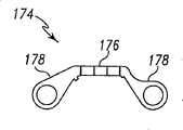
图7示出用于支撑图1中铰接钻的输出小齿轮轴的支架的俯视图;Figure 7 shows a top view of a bracket for supporting the output pinion shaft of the articulated drill in Figure 1;
图8示出图7的支架的侧视图;Figure 8 shows a side view of the stand of Figure 7;
图9示出图1中铰接钻的行星齿轮系统、连接部分和头部分的顶部正视图,其去掉了主壳体和部分头壳体;Figure 9 shows a top elevational view of the planetary gear system, connection section and head section of the articulated drill in Figure 1, with the main housing and part of the head housing removed;
图10示出图1中铰接钻的铰接齿轮传动系统的侧视图,其包括锥齿轮和两个小齿轮;Fig. 10 shows a side view of the articulated gear transmission system of the articulated drill in Fig. 1, which includes a bevel gear and two pinions;
图11示出图1的钻的头壳体部分的透视图,其具有在凹槽中的若干齿,所述若干齿与铰接按钮上的齿互补;Figure 11 shows a perspective view of the bit housing portion of the drill of Figure 1 with teeth in grooves that are complementary to the teeth on the hinge button;
图12示出图1中铰接钻的铰接按钮的透视图;Figure 12 shows a perspective view of the hinged button of the hinged drill in Figure 1;
图13示出图12中铰接按钮的底部的透视图;Figure 13 shows a perspective view of the bottom of the hinge button in Figure 12;
图14示出图1中铰接钻的外壳内表面的局部顶视图,其具有与铰接按钮上的齿相互补的齿和用于容纳铰接按钮的凸起部分的孔;Figure 14 shows a partial top view of the housing inner surface of the hinged drill of Figure 1 with teeth complementary to those on the hinge button and holes for receiving the raised portion of the hinge button;
图15示出图1中铰接钻的外壳内表面的顶视图;Figure 15 shows a top view of the housing inner surface of the articulated drill in Figure 1;
图16示出图1中铰接钻的局部俯视图,其头部分与主壳体部分成直线排列,且没有防尘盖;Fig. 16 shows a partial top view of the articulated drill in Fig. 1, the head portion of which is aligned with the main housing portion without a dust cover;
图17示出图1中铰接钻的局部俯视图,其头部分与主壳体部分成直线排列,带有防尘盖;Fig. 17 shows a partial top view of the articulated drill in Fig. 1, the head portion of which is aligned with the main housing portion, with a dust cover;
图18示出图1中铰接钻的侧视图,其头部分从钻的主壳体部分旋转90度,且移除部分主壳体以示出图17的防尘盖的位置;18 shows a side view of the articulated drill of FIG. 1 with the head portion rotated 90 degrees from the main housing portion of the drill and part of the main housing removed to show the position of the dust cap of FIG. 17;
图19示出图18的铰接钻的侧视图,其头部分从钻的主壳体部分旋转180度,且移除部分主壳体以示出图17的防尘盖的位置;19 shows a side view of the articulated drill of FIG. 18 with the head portion rotated 180 degrees from the main housing portion of the drill and with part of the main housing removed to show the position of the dust cap of FIG. 17;
图20示出图19的防尘盖的详细视图;Figure 20 shows a detailed view of the dust cap of Figure 19;
图21示出图1的铰接钻的透视图,其移除了变速触发开关,离合控制器和一部分主壳体;Figure 21 shows a perspective view of the articulated drill of Figure 1 with the variable speed trigger switch, clutch controller and a portion of the main housing removed;
图22a,22b和22c示出根据本发明的原理,图1的铰接钻的印刷电路板的各个视图;Figures 22a, 22b and 22c show various views of the printed circuit board of the articulated drill of Figure 1 in accordance with the principles of the present invention;
图23示出图21的铰接钻的透视图,其具有可伸缩的防护罩,可伸缩的防护罩具有安装在光发生器和光传感器上面的内部反射表面;FIG. 23 shows a perspective view of the articulated drill of FIG. 21 with a retractable shield having internal reflective surfaces mounted over the light generator and light sensor;
图24示出图1的钻的示意图/方框图,其具有用于马达速度控制的光开关;Figure 24 shows a schematic/block diagram of the drill of Figure 1 with an optical switch for motor speed control;
图25示出螺丝刀形式的钻头的侧视图,该钻头可以用于图1的铰接钻;Figure 25 shows a side view of a drill bit in the form of a screwdriver, which may be used with the articulated drill of Figure 1;
图26示出图25的钻头的剖视图,其正在被插入图1的铰接钻中;Figure 26 shows a cross-sectional view of the drill bit of Figure 25 being inserted into the articulated drill of Figure 1;
图27示出图25的钻头的剖视图,其被插入图1的铰接钻中;Figure 27 shows a cross-sectional view of the drill bit of Figure 25 inserted into the articulated drill of Figure 1;
图28示出根据本发明的原理的锥齿轮的局部顶视图,两个小齿轮呈90度间隔设置;Figure 28 shows a partial top view of a bevel gear with two pinions spaced 90 degrees apart in accordance with the principles of the present invention;
图29示出图28的锥齿轮的局部顶视图,两个小齿轮呈180度间隔设置;Fig. 29 shows a partial top view of the bevel gear of Fig. 28, two pinion gears are arranged at intervals of 180 degrees;
图30示出电动工具的电气图/示意图,其使用马达接口电路动态地制动工具马达,具有半桥的马达接口电路给操作者提供已经到达转矩极限的振动反馈;Figure 30 shows an electrical diagram/schematic of a power tool that dynamically brakes the tool motor using a motor interface circuit with a half-bridge that provides vibratory feedback to the operator that the torque limit has been reached;
图31示出可以用于图1的钻的电路的电气图/示意图,其使用马达接口电路动态地制动工具马达,具有全H桥电路的马达接口电路给操作者提供已经到达转矩极限的振动反馈;和FIG. 31 shows an electrical diagram/schematic of a circuit that may be used with the drill of FIG. 1 to dynamically brake the tool motor using a motor interface circuit with a full H-bridge circuit that provides the operator with an indication that the torque limit has been reached. vibration feedback; and
图32A和32B示出电动工具的电气图/示意图,其响应于来自光开关的变速信号提供固态马达速度控制,且动态地制动马达以指示已经到达转矩极限。32A and 32B show an electrical diagram/schematic of a power tool that provides solid state motor speed control in response to a shift signal from an optical switch, and dynamically brakes the motor to indicate that the torque limit has been reached.
具体实施方式Detailed ways
图1中示出通常指示为100的铰接钻。在图1的实施例中,钻100包括主壳体部分102和头部分104。主壳体部分102容纳马达和相关的控制钻100的电子装置。和本领域已知技术一样,主壳体部分102包括容纳可充电的电池组106的电池座。在一个实施例中,可充电的电池组106包括锂离子电池。通过按压电池释放键来拆下电池组106。图2示出拆下电池组106的钻100。可选择外部电源为钻100供电,例如外部电池或电源线。An articulated drill, generally indicated at 100, is shown in FIG. 1 . In the embodiment of FIG. 1 ,
变速触发开关110控制马达旋转速度。马达旋转方向被反向按钮112所控制,反向按钮112在手指平台114内滑动。通风开口116使冷空气在主壳体部分102内部的马达周围循环。离合控制器118设置使用钻100时所产生的最大转矩。在图1中所示的位置,离合控制器118位于最高设置或钻孔模式。在最高设置,离合器处于不使能状态以提供最大转矩。通过从图1所示的位置向下滑动离合控制器118,用户可以设置所希望的允许钻100产生的极限转矩,这在后续更为详细的介绍。因此,在除最高设置之外的其它设置时,高于离合控制器118设置的转矩使离合器启动。A variable
主壳体部分102还包括模制在主壳体部分102的外表面124上的铰接按钮120和若干角度参考指示器122。在图1的实施例中设有5个角度参考指示器122,用于指示头部分104所处的5个角度位置。The
头部分104包括夹头锁定装置126和角度指示器128。头部分104所处的角度由与角度指示器128对准的角度参考指示器122来指示。如图1所示,头部分104相对于主壳体部分102呈90度设置。在图2中,头部分104与主壳体部分102轴向对齐。尽管图1和2中实施例具有5个角度参考指示器122,也可以设置更多的或更少的角度参考指示器122以及头部分104相对于主壳体部分102所处的相应角度。The
参考图3-6,夹头锁定装置126围绕钻头保持器130,钻头保持器130被球轴承132支撑,球轴承132固定在头壳体136的轴承座134中。夹头锁定装置126包括具有槽140的套筒138。弹簧142定位于钻头保持器130周围。钻头保持器130包括容纳柱销146的孔144和容纳钢球150的槽148。Referring to FIGS. 3-6 , the
在轴承132的外围后部,轴承132邻接头部分104的头壳体136。更为具体地,轴承132邻接凸缘152。在这个实施例中,尽管凸缘可选择地成形为围绕壳体136的内部的若干翼片,凸缘152仍连续围绕壳体136。At the peripheral rear of the
钻头保持器130可操作地与驱动夹头154连接,驱动夹头154通过驱动盘158与输出小齿轮轴156连接,驱动盘158固定连接在输出小齿轮轴156上。锁环160围绕驱动夹头154和三个锁销162。锁环160、驱动夹头154、驱动盘158和锁销162均包括自动主轴锁定系统,以便输出钻头保持器130能够如现有技术所已知的那样仅被从小齿轮侧驱动。当从钻头侧被驱动时,也就是说,当工具100被用作手动螺丝刀时,主轴锁定系统使输出小齿轮轴156不旋转,因而有利于工具100作为手动螺丝刀使用。在可选择的实施例中,可以使用手动操作的锁定设备。The
小齿轮164位于输出小齿轮轴156的相对于驱动盘158的相反端。输出小齿轮轴156的一端通过轴承166保持轴向对准,轴承166安装在轴承座168中。输出小齿轮轴156的相反端被套筒170支撑。套筒170一侧被位于头壳体136上的凸缘172支撑。在相对侧,套筒170被图7和8所示的支架174支撑。
支架174包括与套筒170的一部分互补的支撑面176。两个连接臂178成形为如图9所示与头壳体136连接。支架174消除了为凸缘172提供模制在头壳体136相对侧的匹配凸缘的需求。相对凸缘的需求的消除使得设计的自由度大大增大,这是由于支撑套筒170的支撑结构的空间需求降低了。支架174可以由W108钢冲成,以满足硬度和强度的需要。
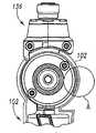
现在参考图10,小齿轮164形成铰接齿轮传动系统180的一部分。铰接齿轮传动系统180还包括在铰接齿轮传动系统180的输出部分与小齿轮164啮合的锥齿轮182,锥齿轮182还通过小齿轮184与马达部分啮合。锥齿轮182的轴186在一端被支撑在框架190的孔188(见图4)中。框架190由锌铝合金ZA-8制成。这种材料提供足够低的摩擦系数,以确保在轴186和框架190之间的摩擦力相对较小。Referring now to FIG. 10 , the
轴186在相反端由球轴承192径向和轴向支撑,球轴承192被框架190支撑。但是,在轴186的该端产生比在轴186插入孔188的一端更大的力。更为具体地,如图10所示,小齿轮164和小齿轮184位于锥齿轮182的相同侧。因此,随着铰接齿轮传动系统180的旋转,在锥齿轮182上产生沿箭头194方向指向锥齿轮182的基部196的力。此力的作用使得锥齿轮182从小齿轮164和小齿轮184上脱离。随着作用在锥齿轮182上的力增大,不可接受的轴向力传递给轴承192。因此,设置推力轴承198来保护球轴承192,并向锥齿轮182的基部196提供低摩擦支撑。推力轴承198由可接受的低摩擦系数的材料制成,例如可以商业上从McMaster Carr ofChicago,Illinois得到的浸油青铜。因此,在锥齿轮182的基部196处所产生的摩擦维持在可接受的水平。
再参考图4,小齿轮184固定连接在行星齿轮箱轴200上,行星齿轮箱轴200接受来自行星齿轮传动系统的转矩。行星齿轮传动系统通常用参考标记202指示。行星齿轮传动系统202接收来自现有技术中已知的马达的转矩。行星齿轮传动系统202位于行星齿轮壳体204内部,行星齿轮壳体204部分插入框架190内部。这种布局使得行星齿轮传动系统202可以独立于其它部件制造,同时简化行星齿轮传动系统202与其它部件的装配。这种模块化还使得在行星齿轮传动系统202中设置可选择的齿轮,同时确保与其它部件的适当安装。Referring again to FIG. 4 , the
通常,希望在行星齿轮壳体204和框架190之间提供简单的摩擦配合。但是,在图4的实施例中,铰接齿轮传动系统180产生沿行星齿轮箱轴200的轴向力。这个轴向力的作用使得行星齿轮壳体204从框架190上脱离。因此,设置穿过行星齿轮壳体204和框架190延伸的销206和208。销206和208确保在钻100操作过程中行星齿轮壳体204不会从框架190上分离。可选择地,行星齿轮壳体204和框架190可以形成为一体单元。In general, it is desirable to provide a simple friction fit between the
继续参照图4,框架190形成为与头壳体136滑动地匹配。为此,头壳体136包括护罩部分210,其围绕球轴承192与框架190相互补地形成。头壳体136还包括容纳框架190的限定孔188的部分的槽212。在图4中还示出包括如图11中所示的若干齿216的插孔214。With continued reference to FIG. 4 , the
进一步参考图12-14,插孔齿216与铰接按钮120上的若干齿218相互补。铰接按钮120包括安装在主壳体部分102中的孔222中的凸起的中央部分220。而且铰接按钮120的齿218形成为与围绕孔222的主壳体部分102内侧上的若干齿224啮合。铰接按钮120还包括在铰接按钮120的面对插孔214的侧面上的弹簧容纳插孔226。当装配以后,弹簧(未示出)位于插孔214内部,且延伸入弹簧容纳插孔226内部,迫使铰接按钮120的凸起的中间部分220朝向铰接按钮120伸入孔222的位置。With further reference to FIGS. 12-14 , the receptacle teeth 216 are complementary to the number of teeth 218 on the
参考图4和15,通过肋228在主壳体部分102内轴向支撑框架190,在此实施例中主壳体部分102由塑料制成。当如图3所示在主壳体部分102中安装框架190时,肋228位于框架190的翼片230下。行星齿轮传动系统202与马达232机械连接,马达232本身与印刷电路板234电连接,印刷电路板234与电池接触保持器236电连接。电池接触保持器236与电池组106上的电池组座紧密配合,而且将电池的电能通过引线(未示出)传递给电路板234。另一对从电路板234向马达端子238延伸的引线(未示出)给马达232传递所需要的电压。Referring to Figures 4 and 15, the
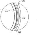
现在参考图5,在头壳体136的围绕锥齿轮182的部分设置间隙240,使得头壳体136相对于主壳体部分102旋转,同时小齿轮164与锥齿轮182啮合。然而,当头部分104与主壳体部分102轴向对齐时,间隙240如图16所示的暴露出来。因此,铰接齿轮传动系统180暴露允许污物进入铰接齿轮传动系统180,这不仅会弄脏铰接齿轮传动系统,还会由于衣服、手指或头发会绊入铰接齿轮传动系统180而出现安全隐患。因此,如图17所示的浮动式防尘盖242被用于防止铰接齿轮传动系统180的污染和避免运动的齿轮通过间隙240暴露给操作者,特别是当如图17中所示,头壳体136与主壳体部分102轴向对齐时更能起到上述作用。Referring now to FIG. 5 ,
如图18-20所示,防尘盖242位于由主壳体部分102和头壳体136所限定的通道244中。通过可移动的防尘盖行程限制器246或框架190的一部分248来限制防尘盖242在通道244下部(如图18和19所述)的位置,防尘盖行程限制器246位于头壳体136上,这在图11和20中最为清楚的示出。通过头壳体136的颈部分250或者主壳体部分102中的边缘252来限制防尘盖242在通道244上部的位置。As shown in FIGS. 18-20 , the
现在参考图3和21-23,离合控制器118与电路板234上的线性电位计254机械连接。光传感器256也位于电路板234上,光传感器256被可伸缩的橡胶防护罩258所覆盖,橡胶防护罩258机械地紧固到变速触发开关110。反射面260(见图24)位于橡胶防护罩258的内侧。机械连接在电路板234上的塑料弹簧定位构件232用于定位和支撑与变速触发开关110机械紧固连接的弹簧264。弹簧264使变速触发开关110围绕枢轴266向远离电路板234的方向偏置。电路板234还包括一个二位滑动开关268,其机械地连接在反向按钮112上。Referring now to FIGS. 3 and 21-23 ,
围绕枢轴266操作变速触发开关110改变反射面260相对于光传感器256的位置,以产生变速控制信号。虽然工具100的实施例中包括了提供变速控制信号的光学信号发生器和接收器,这样的工具可选择地使用压力传感器、电容接近传感器或者电感接近传感器。在这些可选的实施例中,产生可变马达速度控制信号的压力感应开关可以包括产生变速控制信号的压力传感器,所述控制信号与施加给压力传感器的压力相应,所述压力由操作者直接施加或者通过穿越停止位置和全速位置之间的距离的中间构件比如可移动构件施加。Operation of the
由电容接近传感器产生变速控制信号的实施例可以包括产生变速控制信号的电容传感器,变速控制信号与操作者的手指或可移动构件的表面向电容传感器接近所产生的电容相应。由电感接近传感器完成的实施例产生的变速控制信号与操作者的手指或可移动构件的表面向电感传感器接近所产生的电感相应。Embodiments in which the shift control signal is generated by a capacitive proximity sensor may include a capacitive sensor generating a shift control signal corresponding to the capacitance generated by the proximity of an operator's finger or the surface of the movable member to the capacitive sensor. Embodiments implemented by an inductive proximity sensor produce a shift control signal corresponding to the inductance generated by the proximity of the operator's finger or the surface of the movable member to the inductive sensor.
参考图24,示意性地示出工具100的变速控制电路270。变速控制电路270包括可操作地与变速触发开关110连接的电源触头272。光学信号发生器274与电池106连接,且设置在电路板232上,以便从光学信号发生器274发出的光引向变速触发开关110的反射面260并引向光传感器256。Referring to Fig. 24, the variable
光传感器256和光信号发生器274可以位于同一个壳体内或每一个位于一个独立的壳体内。当两个部件位于同一个壳体内时,光发生器和传感器可以通过壳体上的单个观察窗发出和接收光。可选择地,每一个部件可以具有单独的观察窗。在同一个壳体内具有光发生器和传感器的集成部件为加利福尼亚的Fairchild Semiconductor of Sunnyvale公司的QRD1114反射目标传感器。这种壳体比具有滑动片的电位计缩小很多,滑动片穿越的距离与触发开关从停止位置移动到全速位置的距离大致相同。
光信号发生器274和光传感器256可以为红外光发生器和红外光接收器。在可选择的实施例中,IR收发器可以位于柔性的防尘盖内,防尘盖机械的紧固在变速触发开关110的后部。在这个实施例中,在可移动开关附近的盖子的内侧向接收器反射光学信号以产生速度控制信号。The
外部能源,例如太阳,会对包括光传感器256的工具的控制产生负面影响。因此,在一个实施例中,可伸缩的防护罩或防尘盖258由不透明材料制成或者用不透明材料覆盖,以便穿过所述壳体和触发开关泄漏的来自太阳的能量不会影响光传感器256接收的信号。可选择地,对特定频带敏感的光传感器可以用于仅在该特定频带屏蔽光传感器的设备。在进一步的实施例中,可以使用其它电路或程序,用于从干扰能量中唯一确定反射信号的能量。External energy sources, such as the sun, can negatively affect the control of tools including
光传感器256是光学晶体管,具有通过触头272与电池组106连接的集电极276,和通过分压器280和电容282电接地的发射极278。定时信号发生器284接收来自分压器280的电压。尽管也可以使用其它定时信号发生器,但在工具100中,定时信号发生器284是公知的555定时器。The
定时信号发生器284的输出与MOSFET 288的栅极286连接,MOSFET 288的漏极290与一个马达端子238连接,源极292电接地。另一马达端子238通过触头272与电池组106连接。续流二极管294跨接马达端子238。操作性地连接变速触发开关110的旁路触头296与马达端子238和电接地之间的MOSFET 288并联,且制动触头298与续流二极管294并联。The output of
首先参考图24-26介绍钻100的操作。夹头锁定装置126与钻头配合,钻头例如为图25中所示的螺丝刀钻头300。螺丝刀钻头300和钻头保持器130为相互补的形状。尽管还可以用其它形状,但在这个例子中螺丝刀钻头300和钻头保持器130大致为六角形。螺丝刀300钻头的直径比钻头保持器130的直径稍小一些,以便它能够装到钻头保持器130内。螺丝刀钻头300包括缺口区302和尾部304。Operation of the
起初,套筒138从图4所示的位置向右移动到图26所示的位置,从而压缩弹簧142。随着套筒138的移动,套筒138中的凹槽140与钻头保持器130上的凹槽148紧邻。然后,随着螺丝刀钻头300移入钻头保持器130,所述尾部304把钢球150压向凹槽140挤出钻头保持器130的通道,使得尾部304完全通过钢球150。Initially, the
在此处,缺口区302与凹槽148对齐。然后松开套筒138,使得弹簧142将套筒138偏置到钻头保持器130中,其位于从图27中所示的位置向左的位置。如图27所示,随着套筒138的移动,凹槽140远离凹槽148,从而迫使钢球150部分地进入钻头保持器130的通道中。由于缺口区302与凹槽148对齐,从而允许钢球150进入钻头保持器130的通道。此时,钻头300牢固地固定在钻头保持器130中。Here, the notched
然后,头壳体136相对于主壳体部分102铰转到所希望的角度。首先,弹簧容纳插孔226中的弹簧(未示出)推动铰接按钮120延伸入孔222。因此,铰接按钮120的齿218既与主壳体部分102中的齿224啮合,又与头壳体136的插孔214中的齿216啮合,因此呈角度地将铰接按钮120(和头壳体136)和主壳体部分102锁定。另外,如图18所示,防尘盖242在通道244的上部被头壳体136的颈部250限制,且在通道244的下部被框架190的一部分248限制。
然后操作者向铰接按钮120施力,使得弹簧(未示出)被压缩,从而使齿218与齿224脱离。因此,尽管齿218仍然与齿216啮合,头部分104也可以相对于主壳体部分102枢转。例如,当头部分104从图1所示的位置铰转为图2所示的位置时,小齿轮164围绕锥齿轮182铰转。作为例子,当钻100为图1中所示结构时,图28示出小齿轮164和184相对于锥齿轮182的位置。在这个结构中,小齿轮164沿锥齿轮182的周长近似与小齿轮184呈90度分离。当头部分104沿箭头306方向铰转时,小齿轮164沿同样方向围绕锥齿轮182铰转。因此,如图29所示,当头部分104与主壳体部分102在一直线上时,小齿轮164位于锥齿轮182上与小齿轮184呈180度分离。The operator then applies force to hinge
在整个铰转过程中,小齿轮164和184始终保持与锥齿轮182啮合。因此,当头壳体136被铰转时,钻头保持器130可以在马达232的作用下旋转。另外,头壳体136的铰转使得防尘盖行程限制器246与防尘盖242接触,且沿通道244推防尘盖242。因此,如图17所示,防尘盖242比间隙240宽,其限制从钻100的外部接近铰接齿轮传动系统180。
当铰接钻100转向希望的位置时,操作者施加给铰接按钮120的力减小。然后弹簧容纳插孔226中的弹簧(未示出)向铰接按钮120施加远离插孔214的力,直到铰接按钮120穿过孔222。因此,铰接按钮120的齿218既与主壳体部分102中的齿224啮合,又与头壳体136的插孔214中的齿216啮合,因此,呈一定角度的将铰接按钮120(和头壳体136)和主壳体部分102锁定。As the articulating
然后通过用已知的方式根据所希望的旋转方向设置反向按钮112的位置,设置钻头300所希望的旋转方向。通过绕枢轴266移动变速触发开关110来闭合电源触头272,从而执行旋转。触头272的闭合使得电路中电流流向光学信号发生器274从而发光。The desired direction of rotation of the
所发射的光射到反射面260上,并且光的一部分向光传感器256反射。被反射面260所反射的光量随着反射面260向光传感器256的靠近而增大。光传感器256所感应的光的增大使得光传感器256所传导的电流增大,而且通过光传感器256的电流从集电极276流向发射极278。因此,随着作用在光传感器256上的光密度增大,光传感器256所传导的电流增大。电流的增大使得由分压器280提供给定时信号发生器284的电压增大。增大的信号是变速信号,且它使得定时信号发生器284按照已知的方式产生定时信号。尽管可以使用其它的定时信号发生器,但是在所描述的钻100中,定时信号发生器284是公知的555定时器。The emitted light impinges on
定时信号发生器284产生定时脉冲,定时脉冲根据变速信号的大小具有逻辑导通状态。这个信号提供给MOSFET 288的栅极286。当栅极286的信号为逻辑导通状态时,MOSFET 288将一个马达端子238连接到地,同时另一个马达端子238通过主触头272与电池电源连接。因此,当变速触发开关110到达光传感器256开始探测反射光且产生变速信号的位置时,定时信号发生器284开始产生通过MOSFET 288将一个马达端子238连接到地的信号。一旦出现这种情况,电流开始流向MOSFET 288,马达232开始沿反向按钮112所选择的方向旋转。The
当MOSFET 288响应于处于断开状态的定时信号而不导通时,续流二极管294使马达232线圈中的适当的半周期电流从马达232流出,经过二极管294,然后返回马达232。这在续流中是已知的。When
当变速触发开关110位于全速位置时,定时信号主要为导通状态,且旁路触头296闭合。旁路触头296的闭合使得电池电流连续流过马达232,以便马达232以最高的速度旋转。When the variable
当不希望旋转时,操作者释放变速触发开关110,而且弹簧264使变速触发开关110绕枢轴266转动,从而使旁路触头296打开。另外,制动触头298闭合从而连接马达端子238。两个马达端子238通过制动触头298彼此连接使马达动态制动。When rotation is not desired, the operator releases the
所以与现有的控制系统相比,对于产生变速信号的部件来说,工具100的电子控制需要比较小的空间。因为变速触发开关110移动的距离不必与光学信号发生器274和光传感器256匹配,因此可以获得可观的空间效率。另外,光学信号发生器274和光传感器256不需要移动部件,因此可靠性提高了。有利的是,光学信号发生器274和光传感器256可以安装在同一个印刷电路板234上,定时信号发生器284也安装在其上。The electronic control of the
当钻100运转时,钻头300承受轴向力。例如,轴向力来自操作者施加的压力或者钻头的冲击力。在任一种情况中,在不增加铰接齿轮传动系统180内部件体积的前提下保护铰接齿轮传动系统180免受损坏。这通过将来自钻头300的轴向力引导给主壳体部分102而同时避开铰接齿轮传动系统来实现。先参考图27,作用在钻头300上的冲击将钻头300进一步向钻100内移动,或者如图27中向左移动。在现有技术的设计中,这个力不仅会损坏传动系统,还会使将钻头保持在钻头保持器的钢球经常卡阻,从而必须更换夹头锁定装置。When the
但是,如图27所示,设置柱销146以便在缺口区302的壁与钢球150接触之前,钻头300的尾部304与柱销146接触。这样,轴向冲击就不会卡阻钢球150。当然,柱销146必须用足够承受所述轴向冲击的材料制成。根据这个实施例,柱销146用AISI 4135钢制成。However, as shown in FIG. 27 , the
现在参考图4,如果出现轴向冲击,力从柱销146传递给钻头保持器130。来自钻头保持器130的轴向力传递给位于轴承座134内的轴承132。因此,轴向力被传递给头壳体136的凸缘152(也可以参见图5)。此实施例中的头壳体136用铝合金A380制成,以便能够承受轴承132传递的力。然后所述力传递给框架190进入主壳体部分102的肋228。Referring now to FIG. 4 , in the event of an axial shock, force is transferred from
更为具体地,在铰接齿轮传动系统180周围提供两条传递轴向力的路径。第一条路径主要在头壳体136轴向上与主壳体部分102呈一条直线时传递轴向力。在这种结构中,轴向力从头壳体136传到框架190,其主要通过凹槽212并在护罩210处传递,凹槽212位于头壳体136绕孔188与框架190的连接处(见图4),护罩210位于锥齿轮196的基部向外、头壳体136与框架190的连接处。More specifically, two paths for transmitting axial forces are provided around the articulating gear train 180 . The first path transfers axial force primarily when the
第二条路径主要在头壳体136相对于主壳体部分102呈90度角时传递轴向力。在这种结构中,轴向力再次从柱销146传递给钻头保持器130。然后轴向力主要从头壳体136的插孔214中的齿216传递到铰接按钮120上的齿218上,然后传递到主壳体部分102上的齿224上。The second path transfers axial forces primarily when the
当头壳体136没有完全与主壳体部分102对齐也没有相对于主壳体部分102呈90度布置时,轴向力通常通过前述的两条路径来传递。因此,作用在钻100的铰接齿轮传动系统180上的轴向力的影响减小了。因为铰接齿轮传动系统180被保护,铰接齿轮传动系统180可以为比其它铰接齿轮传动系统轻的结构。When the
如图30所示,在一个实施例中,能被用于钻100或其它电动工具的印刷电路板包括向操作者提供振动反馈的电路。振动反馈电路308包括微控制器310,驱动电路312,和马达接口电路314。本实施例中的驱动电路312是集成电路,其由单脉宽调制(PWM)信号、转矩极限指示信号和马达方向控制信号产生用于半桥电路的驱动信号,转矩极限指示信号可以与PWM信号为同一个信号。驱动电路312可以为半桥驱动器,例如是马萨诸塞州,伍斯特市Allegro Microsystems公司的Allegro 3946。As shown in FIG. 30, in one embodiment, a printed circuit board that can be used with a
驱动电路312的输出通过两个晶体管318和320与马达316连接,晶体管318和320可以是MOSFET管,也可以是其它类型的晶体管。晶体管318可以通过开关322和324与马达316的任一个端子连接,同时晶体管320可以通过开关326和328与马达316的两个端子中的一个连接。分流电阻330连接在晶体管320和电接地之间。电阻330的高电位端通过放大器332与微控制器310连接。电源334也设置在振动反馈电路308中,且提供来自转矩参考源336的最大转矩参考信号,转矩参考源336例如可以是线性电位计比如线性电位计254。The output of the
马达316的半桥控制使得不需要续流二极管,因为驱动电路312产生马达接口电路信号,用于可选择地操作马达接口电路314以控制马达316的旋转速度。更为具体地,给微控制器310提供变速控制信号338,用于通过微控制器310调节马达316的旋转,变速控制信号338可以来自触发电位计或者类似的部件。根据变速控制信号338,微控制器310产生供给驱动电路312的PWM信号。响应于PWM信号,驱动电路312使晶体管318和320导通或截止。Half-bridge control of
在通常的操作过程中,晶体管318与晶体管320互补,以便当晶体管320导通时,晶体管318截止。晶体管320被导通和截止的比率决定了马达316的速度。例如,马达316的旋转方向在反向开关的控制下由开关322、324、326和328的位置决定。During normal operation,
当晶体管320处于导通状态时,通过马达316的电流通过晶体管320和电阻330提供到电接地。这个电流与马达316操作时的转矩相关。因此,电阻330高电位端的电压与马达316上的转矩有关。马达转矩信号被放大器332放大,且被提供给微控制器310。微控制器310比较被放大的马达转矩信号和转矩参考源336所设定的转矩极限信号。可选择不同类型转矩极限信号发生器提供的转矩极限信号给微控制器310提供与通过马达316的电流相应的参考信号,此参考信号代表了为马达316设置的最大转矩。When
响应于微控制器310接收到超过马达316的最大设定转矩的马达转矩信号,微控制器310就给驱动电路312输出制动信号。根据制动信号,驱动电路312将晶体管320处于截止状态,且使晶体管318处于导通状态。这使再生电流能够动态制动马达316的旋转。In response to the
在动态制动过程中,马达316上的转矩减小,直到所感应的转矩小于马达316所设定的最大转矩。然后微控制器310使晶体管320返回导通状态,因而旋转马达316,并增大马达316上的转矩。这样,马达316在旋转和动态制动之间切换,引起工具振动,警告操作者已经到达转矩极限。提供振动反馈的有效频率是30Hz。只要触发开关被按下,致使该操作的转矩极限指示信号就继续。可选择地,可以对微控制器编程以产生转矩极限指示信号,用于持续固定的时间后停止以降低马达超载(over-pulsed)的可能性。During dynamic braking, the torque on the
在一个实施例中,利用如图31所示的电路为钻100提供振动反馈。振动反馈电路340包括微控制器342、H桥驱动电路344和马达接口电路346。4个MOSFET管348、350、352和354在H桥驱动电路344的控制下控制可充电的电池组106给马达232提供电能。分流电阻356设置在MOSFET管352、354和电接地之间。电阻356高电位端的信号与马达232产生的转矩相对应。马达转矩信号被放大器电路358放大,并提供给微控制器342。放大器电路358可以由如图31所示的运算放大器执行。微控制器342比较马达转矩信号和转矩极限信号,然后在马达转矩信号等于或大于转矩极限信号时产生转矩极限指示信号。转矩极限指示信号可以为矩形波信号。In one embodiment, vibration feedback is provided to the
在一个实施例中,微控制器342提供转矩极限指示信号,在大约30Hz频率下其为具有至少200微秒截止的矩形信号。转矩极限指示信号使驱动电路344产生马达接口控制信号,此控制信号断开马达232的动力,并且将MOSFET管348、350、352和354连接在一起,以便马达232线圈中的电流通过马达232流回去,从而动态制动马达232。In one embodiment,
动态制动使马达232停止。在下一个导通脉冲到来之前,微控制器使信号反向,反向的信号输入给H桥驱动器344的方向控制输入端。因此,矩形脉冲随后的导通状态使H桥驱动电路344操作H桥,使马达232与可充电电池组106连接,其极性与制动之前用于连接马达232与可充电的电池组106的极性相反。在30Hz频率下制动/反转/起动马达的操作使工具振动,从而提示操作者已经达到转矩极限,同时防止钻头在离合操作过程中连续旋转。动态制动也可以在没有反向所述信号的情况下使用。Dynamic braking stops the
在另一个实施例中,可以产生固定持续时间的矩形波,例如10-20个脉冲,以便马达不会超载。而且,在矩形波的断开时间,微控制器342可以使方向控制信号反向并传输给H桥驱动器344,以便马达232每一次以相反的方向起动。这样导致在离合过程中旋转的净输出为0。另外,响应于指示马达232的反向运转而不是正向运转的马达方向控制信号,微控制器342可以禁用离合功能。In another embodiment, a rectangular wave of fixed duration may be generated, eg 10-20 pulses, so that the motor is not overloaded. Also, during the off time of the rectangular wave, the
图32A和32B示出在工具中使用的电路的实施例,此电路不需要机械触头。电路360包括光学速度控制开关362、正/反双位开关364、微控制器366、驱动电路368、H桥电路370、马达372、分流电阻374、马达转矩信号放大器376和转矩极限信号发生器378。在这个实施例中,电源通过H桥电路370与马达372连接,但是不再需要主触头、制动触头和旁路触头。因此,这个实施例大大地减少了承受机械磨损和退化的部件数量。因为光学速度控制开关362、微控制器366、驱动电路368、H桥电路370和马达转矩信号放大器376都可以用集成电路来实现,而且IC集成电路可以安装在同一印刷电路板上,并且获得了先前的机械触头和可变信号电位计所占据的空间。这种结构还使工具部件能够布置在更为高效的几何空间中。32A and 32B illustrate an embodiment of an electrical circuit for use in a tool that does not require mechanical contacts. The
在电路360中,通过如上所述操作光学速度控制开关362,可以产生由枢转的触发开关的反射面所引导的光学信号的反射所产生变速控制信号。变速控制信号提供给微控制器366来处理。微控制器366可以是TI公司的微控制器,且可以指定器件号为MSP430。用指令编程微控制器366产生PWM脉冲,其具有响应于变速信号的大小的导通状态。微控制器366给驱动电路368提供PWM信号,以产生四个使电池与马达372连接的马达接口控制信号。马达372被驱动的方向由正/反双位开关364的触头决定,通过该触头向微控制器366提供信号。在电路360中,正/反双位开关364的触头上不需要有提供给马达372的电流,因此正/反双位开关364的触头可以比其它系统中的触头小。也通过微控制器366给驱动电路368提供方向信号,因此驱动电路368能够对H桥电路370中的电流进行双向控制。In
马达转矩信号放大器376从分流电阻374的高电位端给微控制器366提供转矩信号。转矩极限信号发生器378可以用如上所述的电位计来实现,以向微控制器366提供参考信号。当微控制器366确定马达转矩信号等于或大于马达转矩极限时,微控制器366产生转矩极限指示信号,以便驱动电路368产生以振动的方式操作马达372的马达接口控制信号。对于TD340驱动电路,由微控制器366产生的转矩极限指示信号是矩形信号,其在大约30Hz的频率下具有至少大约200微秒的断开状态。The motor
虽然通过典型过程和系统部件的描述阐明本发明,虽然各种过程和部件也已经相当详细的描述,但是申请人不倾向于将后续的权利要求的保护范围限制为如此详细。其它优点和修改对本领域技术人员来说是容易的。因此本发明在范围最大的方面不局限于已经示出和描述的特定的细节、实施或阐述性的实施例。因此,在不脱离申请人的总发明构思的精神或范围的前提下可以偏离于这些细节。While the invention has been illustrated by the description of typical processes and system components, and although the various processes and components have also been described in considerable detail, applicants do not intend to limit the scope of protection of the ensuing claims to such detail. Additional advantages and modifications will readily appear to those skilled in the art. Therefore, the invention in its broadest aspects is not limited to the specific details, implementations or illustrative examples that have been shown and described. Accordingly, departures may be made from such details without departing from the spirit or scope of applicant's general inventive concept.
Claims (24)
Translated fromChineseApplications Claiming Priority (3)
| Application Number | Priority Date | Filing Date | Title |
|---|---|---|---|
| US73354605P | 2005-11-04 | 2005-11-04 | |
| US60/733,546 | 2005-11-04 | ||
| PCT/US2006/043144WO2007056254A2 (en) | 2005-11-04 | 2006-11-03 | Articulating drill with integrated circuit board and method of operation |
Publications (2)
| Publication Number | Publication Date |
|---|---|
| CN101300110Atrue CN101300110A (en) | 2008-11-05 |
| CN101300110B CN101300110B (en) | 2013-05-29 |
Family
ID=37794169
Family Applications (5)
| Application Number | Title | Priority Date | Filing Date |
|---|---|---|---|
| CN200680040677.1AExpired - Fee RelatedCN101300732B (en) | 2005-11-04 | 2006-11-03 | Drill with solid state speed control and method of operating |
| CN200680040651.7AExpired - Fee RelatedCN101300110B (en) | 2005-11-04 | 2006-11-03 | Articulating drill with integrated circuit board and method of operation |
| CN200680040563.7AExpired - Fee RelatedCN101300109B (en) | 2005-11-04 | 2006-11-03 | Method and apparatus for providing torque limit feedback in a power drill |
| CN200680040661.0AActiveCN101300111B (en) | 2005-11-04 | 2006-11-03 | Articulated hand-held electric tool and method for an transmitting axial force in electric tool |
| CN200680040702.6AExpired - Fee RelatedCN101300108B (en) | 2005-11-04 | 2006-11-03 | Drill with solid state speed control and method of operating |
Family Applications Before (1)
| Application Number | Title | Priority Date | Filing Date |
|---|---|---|---|
| CN200680040677.1AExpired - Fee RelatedCN101300732B (en) | 2005-11-04 | 2006-11-03 | Drill with solid state speed control and method of operating |
Family Applications After (3)
| Application Number | Title | Priority Date | Filing Date |
|---|---|---|---|
| CN200680040563.7AExpired - Fee RelatedCN101300109B (en) | 2005-11-04 | 2006-11-03 | Method and apparatus for providing torque limit feedback in a power drill |
| CN200680040661.0AActiveCN101300111B (en) | 2005-11-04 | 2006-11-03 | Articulated hand-held electric tool and method for an transmitting axial force in electric tool |
| CN200680040702.6AExpired - Fee RelatedCN101300108B (en) | 2005-11-04 | 2006-11-03 | Drill with solid state speed control and method of operating |
Country Status (5)
| Country | Link |
|---|---|
| US (8) | US7400106B2 (en) |
| EP (5) | EP1943060B1 (en) |
| CN (5) | CN101300732B (en) |
| DE (2) | DE602006020757D1 (en) |
| WO (5) | WO2007056255A2 (en) |
Cited By (6)
| Publication number | Priority date | Publication date | Assignee | Title |
|---|---|---|---|---|
| CN105345751A (en)* | 2010-05-25 | 2016-02-24 | 罗伯特·博世有限公司 | Electric power tool, in particular screw driller |
| CN106426010A (en)* | 2016-10-12 | 2017-02-22 | 戴震班 | Corner device |
| CN108188967A (en)* | 2018-03-28 | 2018-06-22 | 泉州臻美智能科技有限公司 | A kind of electric screw driver with zero offset capability |
| CN109382748A (en)* | 2017-08-09 | 2019-02-26 | 株式会社牧田 | Polishing machine |
| CN111168118A (en)* | 2020-01-10 | 2020-05-19 | 黄晓平 | A disc type part drilling machine for side seam processing |
| US11447108B1 (en)* | 2017-10-30 | 2022-09-20 | Creed Monarch, Inc. | Braking control system and method to sysnchronize the operation of the braking of a towed vehicle |
Families Citing this family (202)
| Publication number | Priority date | Publication date | Assignee | Title |
|---|---|---|---|---|
| DE102004051913A1 (en)* | 2004-08-09 | 2006-02-23 | Robert Bosch Gmbh | Cordless Screwdriver |
| US7552781B2 (en) | 2004-10-20 | 2009-06-30 | Black & Decker Inc. | Power tool anti-kickback system with rotational rate sensor |
| GB2426390B (en) | 2005-05-17 | 2009-02-18 | Milwaukee Electric Tool Corp | Power tool, battery, charger and method of operating the same |
| DE102006023187B4 (en) | 2005-05-17 | 2020-02-27 | Milwaukee Electric Tool Corp. | Method for operating a battery charger and a combination comprising a battery and a battery charger |
| CN101300732B (en)* | 2005-11-04 | 2011-02-23 | 罗伯特·博世有限公司 | Drill with solid state speed control and method of operating |
| US7980159B1 (en) | 2005-11-30 | 2011-07-19 | Western Digital Technologies, Inc. | Methods, devices and systems for screw feeding by vacuum and gravity |
| US7743683B2 (en)* | 2006-08-15 | 2010-06-29 | Umagination Labs, L.P. | Systems and methods of a power tool system with interchangeable functional attachments powered by a direct rotational drive |
| US7802633B2 (en)* | 2006-09-18 | 2010-09-28 | Sp Air Kabushiki Kaisha | Reversible valve assembly for a pneumatic tool |
| US7779931B2 (en)* | 2006-11-10 | 2010-08-24 | Joel Townsan | Electric hand screwdriver with adjustable head |
| DE102006059633B4 (en)* | 2006-12-14 | 2016-12-01 | Robert Bosch Gmbh | impact drill |
| DE102006061625A1 (en)* | 2006-12-27 | 2008-07-03 | Robert Bosch Gmbh | Electric hand tool e.g. drill hammer, has motor connectable with spindle and/or sliding tool over transmission and pivotable around axis, where middle axle of shaft of transmission or central axle of drive shaft forms axis |
| JP5242974B2 (en)* | 2007-08-24 | 2013-07-24 | 株式会社マキタ | Electric tool |
| DE102008052852A1 (en)* | 2007-10-27 | 2009-04-30 | Marquardt Gmbh | Circuit arrangement for a power tool |
| US8407902B2 (en) | 2008-03-07 | 2013-04-02 | Milwaukee Electric Tool Corporation | Reciprocating power tool having a counterbalance device |
| GB2489865B (en)* | 2008-03-07 | 2012-12-19 | Milwaukee Electric Tool Corp | Portable battery-powered reciprocating saw |
| US7823486B2 (en)* | 2008-05-09 | 2010-11-02 | Wise Robert W | Cordless motor assisted torque wrench |
| US20090309527A1 (en)* | 2008-06-16 | 2009-12-17 | General Electric Company | Method and system for dynamic motor braking |
| JP5463014B2 (en)* | 2008-07-04 | 2014-04-09 | 株式会社マキタ | Electric tool |
| US8269612B2 (en) | 2008-07-10 | 2012-09-18 | Black & Decker Inc. | Communication protocol for remotely controlled laser devices |
| USD602756S1 (en)* | 2008-11-26 | 2009-10-27 | C. & E. Fein Gmbh | Oscillating tool |
| JP4961418B2 (en)* | 2008-12-26 | 2012-06-27 | オムロン株式会社 | Electric tool |
| JP5203243B2 (en)* | 2009-02-03 | 2013-06-05 | 株式会社マキタ | Screw tightening tool |
| JP5537055B2 (en)* | 2009-03-24 | 2014-07-02 | 株式会社マキタ | Electric tool |
| US8011444B2 (en)* | 2009-04-03 | 2011-09-06 | Ingersoll Rand Company | Spindle locking assembly |
| CN101876812B (en)* | 2009-04-28 | 2012-07-04 | 南京德朔实业有限公司 | Control method of electric shears |
| US8230570B1 (en) | 2009-06-12 | 2012-07-31 | Western Digital Technologies, Inc. | Automatic gravity vacuum screw feeding |
| DE102009027111A1 (en)* | 2009-06-23 | 2010-12-30 | Robert Bosch Gmbh | Electric machine tool |
| DE102009027317B4 (en)* | 2009-06-30 | 2019-12-05 | Robert Bosch Gmbh | Tool |
| USD623496S1 (en)* | 2009-07-10 | 2010-09-14 | Hitachi Koki Co., Ltd. | Portable electric grinder |
| DE102009027705A1 (en)* | 2009-07-15 | 2011-01-20 | Robert Bosch Gmbh | Hand-held power tool |
| CN101961795A (en)* | 2009-07-23 | 2011-02-02 | 德昌电机(深圳)有限公司 | Electric tool |
| US9071188B2 (en)* | 2009-09-04 | 2015-06-30 | Black & Decker Inc. | Protective redundant subsystem for power tools |
| CN201565933U (en)* | 2009-10-30 | 2010-09-01 | 南京德朔实业有限公司 | Electric hammer |
| JP5394895B2 (en)* | 2009-11-11 | 2014-01-22 | 株式会社マキタ | Electric tool |
| JP5463907B2 (en)* | 2009-12-28 | 2014-04-09 | 日立工機株式会社 | Electric tool |
| JP5351752B2 (en)* | 2009-12-28 | 2013-11-27 | 株式会社マキタ | Electric tool |
| US9475180B2 (en) | 2010-01-07 | 2016-10-25 | Black & Decker Inc. | Power tool having rotary input control |
| US9266230B2 (en)* | 2010-01-07 | 2016-02-23 | Black & Decker Inc. | Twist-handled power tool with locking system |
| US9266178B2 (en) | 2010-01-07 | 2016-02-23 | Black & Decker Inc. | Power tool having rotary input control |
| US8555999B2 (en)* | 2010-04-30 | 2013-10-15 | Black & Decker Inc. | Twist-handled power tool with locking system |
| US8418778B2 (en) | 2010-01-07 | 2013-04-16 | Black & Decker Inc. | Power screwdriver having rotary input control |
| CN102753782B (en) | 2010-01-07 | 2015-09-30 | 布莱克和戴克公司 | There is the electric screw driver rotating input control |
| JP2011156629A (en)* | 2010-02-02 | 2011-08-18 | Makita Corp | Motor control device, electric power tool, and program |
| US20130227809A1 (en) | 2012-02-24 | 2013-09-05 | Pylon Manufacturing Corp. | Wiper blade |
| US20130020102A1 (en)* | 2010-02-17 | 2013-01-24 | Gardena Manufacturing Gmbh | Power Tools |
| JP5510807B2 (en)* | 2010-03-08 | 2014-06-04 | 日立工機株式会社 | Impact tools |
| JP5463987B2 (en)* | 2010-03-17 | 2014-04-09 | 日立工機株式会社 | Electric tool |
| US8584770B2 (en) | 2010-03-23 | 2013-11-19 | Black & Decker Inc. | Spindle bearing arrangement for a power tool |
| US9722334B2 (en) | 2010-04-07 | 2017-08-01 | Black & Decker Inc. | Power tool with light unit |
| CN101837578A (en)* | 2010-05-11 | 2010-09-22 | 南京德朔实业有限公司 | Portable angular tool |
| US20110303432A1 (en)* | 2010-06-14 | 2011-12-15 | Stauffer Joseph G | Power tool transmission |
| EP3756834B1 (en)* | 2010-07-02 | 2021-12-08 | Husqvarna Ab | Battery powered tool |
| CN102371573A (en)* | 2010-08-10 | 2012-03-14 | 南京德朔实业有限公司 | Electric tool |
| USD649421S1 (en)* | 2010-09-09 | 2011-11-29 | Robert Bosch Gmbh | Power tool |
| US9120160B1 (en)* | 2010-10-20 | 2015-09-01 | Ahmed Eldessouky | Positive feed drill |
| US9016395B2 (en) | 2010-11-16 | 2015-04-28 | Milwaukee Electric Tool Corporation | Impact tool |
| DE102010063069A1 (en)* | 2010-12-14 | 2012-06-14 | Robert Bosch Gmbh | Hand tool, in particular drill or Schraubbohrmaschine |
| US9038745B2 (en) | 2010-12-20 | 2015-05-26 | Brigham Young University | Hand power tool and drive train |
| USD670148S1 (en)* | 2011-04-14 | 2012-11-06 | Ching-Yi Wang | Multiple-angle transmission tool |
| US9457768B2 (en) | 2011-04-21 | 2016-10-04 | Pylon Manufacturing Corp. | Vortex damping wiper blade |
| EP2524773B1 (en) | 2011-05-19 | 2017-06-21 | Black & Decker Inc. | Electronic power apparatus for a power tool |
| US8789446B1 (en) | 2011-06-28 | 2014-07-29 | Western Digital Technologies, Inc. | Screw feeding apparatus to deliver a screw from a vibrating rail to a screw guide tube |
| MX345011B (en) | 2011-07-28 | 2017-01-11 | Pylon Mfg Corp | Windshield wiper adapter, connector and assembly. |
| US9108595B2 (en) | 2011-07-29 | 2015-08-18 | Pylon Manufacturing Corporation | Windshield wiper connector |
| DE102011109133B4 (en)* | 2011-08-02 | 2020-10-22 | Robert Bosch Gmbh | Transportable screwdriving tool with integrated switching element |
| US8493172B2 (en)* | 2011-09-30 | 2013-07-23 | Snap-On Incorporated | Variable speed toggle trigger |
| US20130133210A1 (en) | 2011-11-30 | 2013-05-30 | Robert Bosch Gmbh | Articulating Jig Saw |
| EP2799188A4 (en)* | 2011-12-28 | 2015-08-12 | Positec Power Tools Suzhou Co | Power tool |
| US8881409B2 (en) | 2012-01-16 | 2014-11-11 | Robert Bosch Gmbh | Articulating oscillating power tool |
| US9908182B2 (en) | 2012-01-30 | 2018-03-06 | Black & Decker Inc. | Remote programming of a power tool |
| US20130200823A1 (en)* | 2012-02-02 | 2013-08-08 | Conair Corporation | Motor for hair grooming apparatus |
| TW201332725A (en)* | 2012-02-10 | 2013-08-16 | Master Air Tool Co Ltd | Pneumatic tool head structure |
| US10723322B2 (en) | 2012-02-24 | 2020-07-28 | Pylon Manufacturing Corp. | Wiper blade with cover |
| US20130219649A1 (en) | 2012-02-24 | 2013-08-29 | Pylon Manufacturing Corp. | Wiper blade |
| EP2631035B1 (en) | 2012-02-24 | 2019-10-16 | Black & Decker Inc. | Power tool |
| US9193055B2 (en) | 2012-04-13 | 2015-11-24 | Black & Decker Inc. | Electronic clutch for power tool |
| US9259790B2 (en)* | 2012-04-23 | 2016-02-16 | Black & Decker Inc. | Power tool with automatic chuck |
| DE102012206884A1 (en)* | 2012-04-26 | 2013-10-31 | Robert Bosch Gmbh | Hand tool |
| US9450471B2 (en) | 2012-05-24 | 2016-09-20 | Milwaukee Electric Tool Corporation | Brushless DC motor power tool with combined PCB design |
| US8919456B2 (en) | 2012-06-08 | 2014-12-30 | Black & Decker Inc. | Fastener setting algorithm for drill driver |
| US20130327552A1 (en) | 2012-06-08 | 2013-12-12 | Black & Decker Inc. | Power tool having multiple operating modes |
| DE202013103023U1 (en)* | 2012-07-14 | 2013-10-04 | Hitachi Koki Co., Ltd. | power tool |
| GB201212958D0 (en)* | 2012-07-20 | 2012-09-05 | Hosking Peter J | Power tools |
| US10829092B2 (en) | 2012-09-24 | 2020-11-10 | Pylon Manufacturing Corp. | Wiper blade with modular mounting base |
| DE102012221748A1 (en)* | 2012-11-28 | 2014-05-28 | Robert Bosch Gmbh | Hand tool |
| EP3189940B1 (en)* | 2012-12-25 | 2018-01-31 | Makita Corporation | Impact tool |
| US9956676B2 (en) | 2013-01-09 | 2018-05-01 | Techtronic Power Tools Technology Limited | Tool with rotatable head |
| US9550283B2 (en) | 2013-01-24 | 2017-01-24 | Ingersoll-Rand Company | Power tool with spindle lock |
| US20150328764A1 (en) | 2013-02-01 | 2015-11-19 | Makita Corporation | Power tool |
| JP2014148006A (en)* | 2013-02-01 | 2014-08-21 | Makita Corp | Electric power tool and portable circular saw |
| EP2961572B1 (en) | 2013-02-26 | 2016-09-21 | Apex Brands, Inc. | Low pressure shut off for a pneumatic tool |
| US10668613B2 (en) | 2013-03-14 | 2020-06-02 | Robert Bosch Tool Corporation | Slide switch for a power tool |
| US10166951B2 (en) | 2013-03-15 | 2019-01-01 | Pylon Manufacturing Corp. | Windshield wiper connector |
| US9150360B1 (en) | 2013-05-16 | 2015-10-06 | Western Digital Technologies, Inc. | Mechanism to deliver fastener vertically |
| US9787159B2 (en) | 2013-06-06 | 2017-10-10 | Milwaukee Electric Tool Corporation | Brushless DC motor configuration for a power tool |
| WO2014201174A1 (en)* | 2013-06-11 | 2014-12-18 | Spin Chill Corp. | Container spinning device and method of use thereof |
| US9889066B2 (en) | 2013-07-01 | 2018-02-13 | Good Fortune 5, Llc | Massaging device having a heat sink |
| US9265551B2 (en) | 2013-07-19 | 2016-02-23 | Pro-Dex, Inc. | Torque-limiting screwdrivers |
| US9559628B2 (en) | 2013-10-25 | 2017-01-31 | Black & Decker Inc. | Handheld power tool with compact AC switch |
| GB2519962A (en)* | 2013-11-01 | 2015-05-13 | Robert Fowler | A handheld power tool |
| DE102013223819A1 (en)* | 2013-11-21 | 2015-05-21 | Robert Bosch Gmbh | Hand tool housing device |
| DE102013224759A1 (en)* | 2013-12-03 | 2015-06-03 | Robert Bosch Gmbh | Machine tool device |
| US10014128B2 (en)* | 2013-12-17 | 2018-07-03 | Robert Bosch Tool Corporation | Portable power tool with trigger switch, trigger release and lock-on mechanism combination |
| CN104723259B (en)* | 2013-12-20 | 2018-01-16 | 南京德朔实业有限公司 | Impact screwdriver |
| US9505380B2 (en) | 2014-03-07 | 2016-11-29 | Pylon Manufacturing Corp. | Windshield wiper connector and assembly |
| US9561568B2 (en)* | 2014-04-25 | 2017-02-07 | Black & Decker Inc. | Magnetic drill press with alternate power source |
| US20160039012A1 (en)* | 2014-08-11 | 2016-02-11 | Hsiu-Lin HSU | Magnetic Coupling Spindle For Automatic Screwdrivers |
| CN107251264B (en) | 2014-11-26 | 2020-10-13 | 创科实业有限公司 | Battery |
| JP6357086B2 (en)* | 2014-11-26 | 2018-07-11 | 株式会社マキタ | Electric equipment |
| EP3251801A4 (en)* | 2015-01-28 | 2018-09-19 | Koki Holdings Kabushiki Kaisha | Impact tool |
| US10406662B2 (en)* | 2015-02-27 | 2019-09-10 | Black & Decker Inc. | Impact tool with control mode |
| US10697250B2 (en)* | 2015-04-02 | 2020-06-30 | Sandvik Intellectual Property Ab | Multi-functional connector, drill head, and method |
| US10637379B2 (en)* | 2015-04-07 | 2020-04-28 | Black & Decker Inc. | Power tool with automatic feathering mode |
| KR102074052B1 (en)* | 2015-06-02 | 2020-02-05 | 밀워키 일렉트릭 툴 코포레이션 | Multi-speed power tools with electronic clutch |
| CN107635726A (en)* | 2015-06-05 | 2018-01-26 | 英古所连公司 | Power tool with user's selectively actuatable pattern |
| WO2016196918A1 (en) | 2015-06-05 | 2016-12-08 | Ingersoll-Rand Company | Power tool user interfaces |
| WO2016196979A1 (en) | 2015-06-05 | 2016-12-08 | Ingersoll-Rand Company | Impact tools with ring gear alignment features |
| US11260517B2 (en) | 2015-06-05 | 2022-03-01 | Ingersoll-Rand Industrial U.S., Inc. | Power tool housings |
| WO2016196984A1 (en) | 2015-06-05 | 2016-12-08 | Ingersoll-Rand Company | Power tools with user-selectable operational modes |
| US11957635B2 (en) | 2015-06-20 | 2024-04-16 | Therabody, Inc. | Percussive therapy device with variable amplitude |
| US10357425B2 (en) | 2015-06-20 | 2019-07-23 | Theragun, LLC | Massage device and method of use |
| US10857064B2 (en) | 2018-12-26 | 2020-12-08 | Theragun, Inc. | Percussive therapy device |
| US10702448B2 (en) | 2017-03-14 | 2020-07-07 | Theragun, Inc. | Percussive massage device and method of use |
| US11160721B2 (en) | 2015-06-20 | 2021-11-02 | Theragun, Inc. | Percussive therapy device with variable amplitude |
| US9659468B2 (en)* | 2015-09-16 | 2017-05-23 | Immersion Corporation | Haptic feedback in a haptically noisy environment |
| JP6513006B2 (en)* | 2015-09-30 | 2019-05-15 | 株式会社マキタ | Motor control device |
| WO2017075066A1 (en) | 2015-10-26 | 2017-05-04 | Pylon Manufacturing Corp. | Wiper blade |
| KR101782535B1 (en)* | 2016-01-28 | 2017-10-24 | 대모 엔지니어링 주식회사 | Hydraulic breaker |
| JP6758853B2 (en)* | 2016-02-22 | 2020-09-23 | 株式会社マキタ | Angle tool |
| JP6555167B2 (en)* | 2016-03-25 | 2019-08-07 | 株式会社安川電機 | Electric motor and brake release method |
| WO2017201485A1 (en) | 2016-05-19 | 2017-11-23 | Pylon Manufacturing Corp. | Windshield wiper connector |
| WO2017201470A1 (en) | 2016-05-19 | 2017-11-23 | Pylon Manufacturing Corp. | Windshield wiper connector |
| WO2017201458A1 (en) | 2016-05-19 | 2017-11-23 | Pylon Manufacturing Corp. | Windshield wiper connector |
| EP3458315B1 (en) | 2016-05-19 | 2021-09-08 | Pylon Manufacturing Corp. | Windshield wiper blade |
| US11040705B2 (en) | 2016-05-19 | 2021-06-22 | Pylon Manufacturing Corp. | Windshield wiper connector |
| WO2017214194A1 (en) | 2016-06-07 | 2017-12-14 | Pro-Dex, Inc. | Torque-limiting screwdriver devices, systems, and methods |
| US10589413B2 (en) | 2016-06-20 | 2020-03-17 | Black & Decker Inc. | Power tool with anti-kickback control system |
| JP6758960B2 (en)* | 2016-07-05 | 2020-09-23 | 株式会社マキタ | Rechargeable power tool |
| CN106122233B (en)* | 2016-07-20 | 2018-10-12 | 上海宇航系统工程研究所 | The not de- clamp device of pine and its electric wrench |
| US10220493B2 (en) | 2016-09-06 | 2019-03-05 | Ingersoll-Rand Company | Spindle lock mechanism for pneumatic right-angle impact tool |
| US10625405B2 (en) | 2016-09-13 | 2020-04-21 | Milwaukee Electric Tool Corporation | Powered ratcheting torque wrench |
| US11453105B2 (en) | 2016-09-13 | 2022-09-27 | Milwaukee Electric Tool Corporation | Powered ratcheting torque wrench |
| DE102016117783B4 (en)* | 2016-09-21 | 2023-11-16 | Johnson Electric Germany GmbH & Co. KG | Electric switch |
| US10427270B2 (en) | 2016-10-01 | 2019-10-01 | Ingersoll-Rand Company | Belt sander ergonomic articulating arm belt with button release, lock, and sealed housing |
| US10875168B2 (en) | 2016-10-07 | 2020-12-29 | Makita Corporation | Power tool |
| JP6863704B2 (en) | 2016-10-07 | 2021-04-21 | 株式会社マキタ | Strike tool |
| WO2018088443A1 (en)* | 2016-11-10 | 2018-05-17 | 日東工器株式会社 | Electric tool, and control device and control circuit for same |
| CN106863619A (en)* | 2017-02-17 | 2017-06-20 | 苏州益普敦新材料科技有限公司 | A kind of mixing of construction material with opening cycle of higher pressure boring device soon |
| US10608501B2 (en) | 2017-05-24 | 2020-03-31 | Black & Decker Inc. | Variable-speed input unit having segmented pads for a power tool |
| US11097405B2 (en) | 2017-07-31 | 2021-08-24 | Ingersoll-Rand Industrial U.S., Inc. | Impact tool angular velocity measurement system |
| JP6920441B2 (en) | 2017-08-03 | 2021-08-18 | 株式会社マキタ | Electric wrench |
| JP6953252B2 (en)* | 2017-09-19 | 2021-10-27 | 株式会社マキタ | Rotating tool |
| EP3476543A1 (en)* | 2017-10-26 | 2019-05-01 | Max Co., Ltd. | Tool and electric tool |
| CN109755975B (en)* | 2017-11-02 | 2021-12-07 | 苏州宝时得电动工具有限公司 | Electric tool control method and circuit |
| US10889474B2 (en)* | 2017-12-08 | 2021-01-12 | Hall Labs Llc | Battery cell shifting in rotational motor applications |
| CN109199525B (en)* | 2017-12-20 | 2024-08-20 | 上海博进医疗器械有限公司 | Multifunctional medical bone drill |
| US12010799B2 (en)* | 2018-06-28 | 2024-06-11 | Black & Decker Inc. | Electronic switch module with oppositely-arranged power switches and discrete heat sinks |
| TWI660806B (en)* | 2018-07-09 | 2019-06-01 | 愛烙達股份有限公司 | Hand-held tool |
| CN112566754B (en) | 2018-08-20 | 2023-04-18 | 普罗德克斯有限公司 | Torque limiting device, system and method |
| JP7326997B2 (en)* | 2018-09-07 | 2023-08-16 | マックス株式会社 | binding machine |
| ES2987261T3 (en)* | 2018-09-07 | 2024-11-14 | Max Co Ltd | Binder |
| US11890253B2 (en) | 2018-12-26 | 2024-02-06 | Therabody, Inc. | Percussive therapy device with interchangeable modules |
| US10959911B2 (en) | 2018-12-26 | 2021-03-30 | Theragun, Inc. | Percussive therapy device with active control |
| US11357697B2 (en) | 2018-12-26 | 2022-06-14 | Therabody, Inc. | Percussive therapy device |
| US12064387B2 (en) | 2018-12-26 | 2024-08-20 | Therabody, Inc. | Percussive therapy device with electrically connected attachment |
| US10940081B2 (en) | 2019-05-07 | 2021-03-09 | Theragun, Inc. | Percussive massage device with force meter |
| US11564860B2 (en) | 2018-12-26 | 2023-01-31 | Therabody, Inc. | Percussive therapy device with electrically connected attachment |
| US11432994B2 (en) | 2018-12-26 | 2022-09-06 | Therabody, Inc. | Intelligence engine system and method |
| US11452670B2 (en) | 2018-12-26 | 2022-09-27 | Therabody, Inc. | Percussive therapy device with orientation, position, and force sensing and accessory therefor |
| US11897094B2 (en)* | 2019-01-07 | 2024-02-13 | Milwaukee Electric Tool Corporation | Powered ratcheting wrench |
| JP7246202B2 (en) | 2019-02-19 | 2023-03-27 | 株式会社マキタ | Power tool with vibration mechanism |
| JP7229807B2 (en) | 2019-02-21 | 2023-02-28 | 株式会社マキタ | Electric tool |
| US11945087B2 (en) | 2019-03-29 | 2024-04-02 | Tien-I Industrial Co., Ltd. | Impact tool head |
| US11813221B2 (en) | 2019-05-07 | 2023-11-14 | Therabody, Inc. | Portable percussive massage device |
| US11998504B2 (en) | 2019-05-07 | 2024-06-04 | Therabody, Inc. | Chair including percussive massage therapy |
| EP3981066A4 (en) | 2019-06-10 | 2023-02-08 | Milwaukee Electric Tool Corporation | MOTOR BRAKING USING SELECTIVELY LINKABLE RESISTOR |
| DE102019213720A1 (en)* | 2019-09-10 | 2021-03-11 | Robert Bosch Gmbh | Hand machine tool and method for operating the hand machine tool |
| EP3792009B1 (en)* | 2019-09-12 | 2024-04-24 | Andreas Stihl AG & Co. KG | Hand-guided appliance with a tool |
| DE102019215415A1 (en)* | 2019-10-09 | 2021-04-15 | Robert Bosch Gmbh | Method for teaching in application shutdowns with the help of finding characteristic signal forms when operating a handheld power tool |
| JP7178591B2 (en)* | 2019-11-15 | 2022-11-28 | パナソニックIpマネジメント株式会社 | Impact tool, impact tool control method and program |
| CN110880855B (en)* | 2019-11-28 | 2020-09-18 | 山东三木环保工程有限公司 | Working method of linear motor driven tamping tool |
| US11806095B2 (en) | 2020-06-17 | 2023-11-07 | Mazor Robotics Ltd. | Torque sensor with decision support and related systems and methods |
| DE102020212936A1 (en) | 2020-10-14 | 2022-04-14 | Robert Bosch Gesellschaft mit beschränkter Haftung | Electronic H-bridge control |
| TWI750884B (en)* | 2020-11-04 | 2021-12-21 | 朝程工業股份有限公司 | electrical tools |
| CN114643566A (en)* | 2020-12-18 | 2022-06-21 | 南京泉峰科技有限公司 | Electric tool |
| US20220286132A1 (en)* | 2021-03-04 | 2022-09-08 | Snap-On Incorporated | Non-contact direction selector mechanism |
| US12343302B2 (en) | 2021-08-13 | 2025-07-01 | Hyperice Ip Subco, Llc | Combination applicator and adapter for percussive massage device |
| JP2023027867A (en)* | 2021-08-18 | 2023-03-03 | 瓜生製作株式会社 | Electric power tool comprising trigger switch using light sensor |
| CN114274063A (en)* | 2021-11-25 | 2022-04-05 | 中之捷(常州)汽车零部件再制造有限公司 | Handheld electric disassembling clamp |
| US12226884B2 (en) | 2021-11-29 | 2025-02-18 | Ingersoll-Rand Industrial U.S., Inc. | High resolution anvil angle sensor |
| SE545773C2 (en)* | 2021-12-10 | 2024-01-09 | Atlas Copco Ind Technique Ab | Method of controlling an electric motor of a tightening tool |
| US11857481B2 (en) | 2022-02-28 | 2024-01-02 | Therabody, Inc. | System for electrical connection of massage attachment to percussive therapy device |
| DE202023002791U1 (en)* | 2022-04-07 | 2024-07-10 | Milwaukee Electric Tool Corporation | Powered ratchet tool |
| WO2024044546A1 (en)* | 2022-08-22 | 2024-02-29 | Milwaukee Electric Tool Corporation | Motor arrangements for a power tool |
| CN115139257B (en)* | 2022-09-05 | 2023-03-24 | 江苏华频电子科技有限公司 | Multifunctional electric tool for offline testing and sorting equipment |
| US12295900B1 (en) | 2022-12-21 | 2025-05-13 | Therabody, Inc. | Systems, methods, and devices for percussive massage therapy with voice activation |
| USD1057782S1 (en)* | 2023-01-09 | 2025-01-14 | Jianlin Wang | Welding torch for bumper repair |
| WO2024229548A1 (en) | 2023-05-05 | 2024-11-14 | New World Technologies Inc. | A torque tool with fault protection and a method of operating the same |
| US12402686B2 (en) | 2023-06-14 | 2025-09-02 | Therabody, Inc. | Articles of footwear having therapeutic assemblies |
| DE102023208181A1 (en) | 2023-08-28 | 2025-03-06 | Robert Bosch Gesellschaft mit beschränkter Haftung | Hand tool with a first and second housing section |
| WO2025059992A1 (en) | 2023-09-21 | 2025-03-27 | Therabody, Inc. | Systems, methods, and devices for percussive massage therapy |
| DE102023212477A1 (en)* | 2023-12-11 | 2025-06-12 | Robert Bosch Gesellschaft mit beschränkter Haftung | hand tool |
Family Cites Families (181)
| Publication number | Priority date | Publication date | Assignee | Title |
|---|---|---|---|---|
| US66052A (en)* | 1867-06-25 | smith | ||
| US1324258A (en) | 1919-12-09 | Hand-tool | ||
| US1806582A (en) | 1931-05-26 | Portable electric saw | ||
| US551418A (en)* | 1895-12-17 | Handle for brake-staffs | ||
| US661418A (en)* | 1900-02-24 | 1900-11-06 | Dennis Nunan | Universal brace and drill. |
| US1202851A (en) | 1915-04-13 | 1916-10-31 | Robert Emmett Kelly | Back-brace. |
| US2097878A (en)* | 1934-01-15 | 1937-11-02 | Grabe Alf Gerhard | Antifriction bearing and method of manufacturing the same |
| US2106937A (en)* | 1936-03-04 | 1938-02-01 | Jr John E Torbert | Drill |
| US2198397A (en)* | 1937-03-19 | 1940-04-23 | Szekely Company Inc | Variable speed transmission |
| US2155082A (en)* | 1937-03-23 | 1939-04-18 | Black & Decker Mfg Co | Portable electric tool and casing |
| US2348266A (en)* | 1941-10-28 | 1944-05-09 | Christian A Andresen | Angle toolholder |
| US2414637A (en) | 1944-05-17 | 1947-01-21 | Aircraft Tools Inc | Universal drill support |
| US2546655A (en) | 1947-08-06 | 1951-03-27 | Shaler Saul | Adjustable hand-drill |
| US2791142A (en) | 1955-08-29 | 1957-05-07 | Chester S Lyon | Gear operated angularly adjustable socket wrench |
| US3006202A (en)* | 1958-03-17 | 1961-10-31 | Samuel J Forbes | Rotary and percussive tool |
| US3109238A (en) | 1961-11-28 | 1963-11-05 | Samuel B Marks | Portable dental drill |
| US3203275A (en)* | 1962-11-26 | 1965-08-31 | Vaino A Hoover | Mechanical actuator |
| US3316379A (en)* | 1965-07-29 | 1967-04-25 | Texas Instruments Inc | Seal for push button actuated device |
| US3427520A (en) | 1965-12-27 | 1969-02-11 | Collins Radio Co | Dc servo amplifier for armature drive motor |
| DE1588032A1 (en) | 1966-03-18 | 1970-06-25 | Biviator Sa | Electrical limiting circuit |
| US3475676A (en) | 1966-12-28 | 1969-10-28 | Jearld L Hutson | Photosensitive power control system |
| US3525883A (en)* | 1967-07-28 | 1970-08-25 | Dover Corp | Bridge amplifier circuit |
| US3742364A (en) | 1971-10-22 | 1973-06-26 | Lucerne Products Inc | Reversing switch lever |
| US3840789A (en)* | 1973-01-31 | 1974-10-08 | Russell A Co Inc | Control circuit for vibratory devices |
| US3892146A (en) | 1973-08-31 | 1975-07-01 | Shibaura Engineering Works Ltd | Electric control for an electric motor operated nut fastening tool |
| US3904943A (en) | 1974-05-15 | 1975-09-09 | California Computer Products | Capstan servo system |
| DE2432421B2 (en) | 1974-07-05 | 1977-08-25 | Siemens AG, 1000 Berlin und 8000 München | OPTICAL SWITCH |
| US4267914A (en) | 1979-04-26 | 1981-05-19 | Black & Decker Inc. | Anti-kickback power tool control |
| JPS55155689A (en)* | 1979-05-23 | 1980-12-04 | Janome Sewing Machine Co Ltd | Speed controller for sewing machine |
| US4296654A (en)* | 1979-08-20 | 1981-10-27 | Mercer Albert E | Adjustable angled socket wrench extension |
| US4307325A (en)* | 1980-01-28 | 1981-12-22 | Black & Decker Inc. | Digital control system for electric motors in power tools and the like |
| US4412158A (en)* | 1980-02-21 | 1983-10-25 | Black & Decker Inc. | Speed control circuit for an electric power tool |
| US4332147A (en) | 1980-03-17 | 1982-06-01 | Leonard Grech | Adjustable power transmitting device |
| US4317176A (en)* | 1980-03-24 | 1982-02-23 | Black & Decker Inc. | Microcomputer controlled power tool |
| US4347450A (en) | 1980-12-10 | 1982-08-31 | Colligan Wallace M | Portable power tool |
| US4479516A (en)* | 1982-02-08 | 1984-10-30 | Hunter Frank M | Electrically driven toothbrush |
| US4489267A (en)* | 1982-02-12 | 1984-12-18 | Black & Decker Inc. | Waveform synthesizer and motor controller |
| DE3210929A1 (en)* | 1982-03-25 | 1983-10-06 | Bosch Gmbh Robert | METHOD AND DEVICE FOR SWITCHING OFF SCREWING DEVICES |
| US4399495A (en)* | 1982-06-04 | 1983-08-16 | Cloverline, Inc. | Flashlight |
| US4513381A (en)* | 1982-06-07 | 1985-04-23 | The Singer Company | Speed regulator for power tool |
| JPS5914476A (en)* | 1982-07-16 | 1984-01-25 | 松下電工株式会社 | Electric driver |
| JPS5969271A (en)* | 1982-10-13 | 1984-04-19 | 第一電通株式会社 | Screw clamping device using induction motor |
| JPS59113499U (en)* | 1983-01-20 | 1984-07-31 | 青輪企業股ふん有限公司 | Joint device for folding ladders, furniture, etc. |
| US4581565A (en) | 1983-03-01 | 1986-04-08 | Storage Technology Corporation | H-bridge power amplifier and method for controlling the same |
| JPS6020870A (en)* | 1983-07-12 | 1985-02-02 | 日立工機株式会社 | Control method of clutch type electric tightening tool |
| US4544869A (en) | 1983-10-05 | 1985-10-01 | Unisen, Inc. | Electronic control circuit for bi-directional motion |
| US4528486A (en)* | 1983-12-29 | 1985-07-09 | The Boeing Company | Controller for a brushless DC motor |
| US4527103A (en)* | 1984-06-08 | 1985-07-02 | General Motors Corporation | Four state DC motor controller |
| JPS61154495A (en) | 1984-12-27 | 1986-07-14 | Sankyo Seiki Mfg Co Ltd | Drive controller of dc motor |
| US4649245A (en) | 1985-08-09 | 1987-03-10 | Black & Decker Inc. | Variable speed trigger switch |
| IT206270Z2 (en)* | 1985-10-09 | 1987-07-20 | Vimercati Off Mec | PUSH BUTTON WATERPROOF SWITCH |
| US4705997A (en) | 1986-02-21 | 1987-11-10 | United Technologies Automotive, Inc. | Bidirectional motor drive circuit |
| US4719395A (en)* | 1986-12-22 | 1988-01-12 | Omron Tateisi Electronics Co. | Variable speed control switch for an electric tool including a DC motor |
| US4782726A (en)* | 1987-01-13 | 1988-11-08 | Ryder Internation Corporation | Lead screw driver |
| JP2502077B2 (en) | 1987-02-28 | 1996-05-29 | 株式会社日立製作所 | Elevator guide device |
| DE3718309A1 (en)* | 1987-05-21 | 1988-12-15 | Vdo Schindling | CIRCUIT ARRANGEMENT FOR THE CLOCKED CONTROL OF SEMICONDUCTOR SWITCHES |
| US4816726A (en) | 1987-09-14 | 1989-03-28 | United Technologies Corporation | Method of and arrangement for controlling and h-bridge electric motor |
| US5122146A (en) | 1988-02-04 | 1992-06-16 | Pfizer Hospital Products Group, Inc. | Apparatus for reducing a fracture |
| US5022118A (en)* | 1990-06-25 | 1991-06-11 | Wan Dean Industry Co. | Ladder joint with engagement spring member |
| US5365155A (en) | 1990-10-22 | 1994-11-15 | Marquardt Gmbh | Rotational speed control and use of same to control the rotational speed of an electric hand tool motor |
| US5211471A (en)* | 1990-12-28 | 1993-05-18 | The Brinkmann Corporation | Flashlight with tailcap switch boot |
| US5170779A (en)* | 1991-01-22 | 1992-12-15 | Ginsberg Irwin A | Automated ear cleansing device |
| US5238461A (en)* | 1991-02-11 | 1993-08-24 | Gotman Alexander S | Reactionlless differential rotary driver having optimized output torques |
| US5149230A (en)* | 1991-03-04 | 1992-09-22 | Nett Daniel R | Rotating dual attachment receptacle apparatus tool |
| US5161437A (en)* | 1991-04-17 | 1992-11-10 | Maeda Metal Industries, Ltd. | Device for tightening up nut on bolt |
| DE4116343A1 (en)* | 1991-05-18 | 1992-11-19 | Bosch Gmbh Robert | HAND-MADE ELECTRIC TOOL, ESPECIALLY DRILLING MACHINE |
| US5360946A (en)* | 1991-09-17 | 1994-11-01 | International Business Machines Corporation | Flex tape protective coating |
| US5177424A (en) | 1991-09-20 | 1993-01-05 | Welch Allyn, Inc. | Instrument handle for use with interchangeable batteries |
| US5165172A (en)* | 1992-01-16 | 1992-11-24 | Pennies From Heaven, Inc. | Adjustable hair clipper |
| JPH05258641A (en)* | 1992-03-16 | 1993-10-08 | Matsushita Electric Ind Co Ltd | Panel switch |
| US5332954A (en) | 1992-03-30 | 1994-07-26 | Solaria Research Enterprises Ltd. | Optimal DC motor/controller configuration |
| US5331258A (en)* | 1992-03-30 | 1994-07-19 | Solaria Research Enterprises, Ltd. | Synchronous-rectification type control for direct current motors and method of making |
| US5414637A (en)* | 1992-06-24 | 1995-05-09 | International Business Machines Corporation | Intra-module spare routing for high density electronic packages |
| US5410229A (en) | 1992-07-31 | 1995-04-25 | Black & Decker Inc. | Motor speed control circuit with electronic clutch |
| JP3225700B2 (en)* | 1992-08-04 | 2001-11-05 | 松下電器産業株式会社 | Method and apparatus for manufacturing liquid crystal panel |
| US5428522A (en)* | 1992-08-17 | 1995-06-27 | Kaman Electromagnetics Corporation | Four quadrant unipolar pulse width modulated inverter |
| US5251706A (en)* | 1992-12-03 | 1993-10-12 | Jack Evans | Ratchet drive tool with manual and non-manual power actuation |
| US5327794A (en)* | 1992-12-09 | 1994-07-12 | Ihc Holland N.V. | Device for driving a tool positioned on a pivotable part |
| US5363155A (en)* | 1993-02-18 | 1994-11-08 | Ehud Urinowski | Eye examination apparatus and accessory therefor |
| GB9320181D0 (en)* | 1993-09-30 | 1993-11-17 | Black & Decker Inc | Improvements in and relating to power tools |
| US5565760A (en)* | 1994-11-02 | 1996-10-15 | General Electric Company | Electrical propulsion systems for a golf car |
| US6479958B1 (en) | 1995-01-06 | 2002-11-12 | Black & Decker Inc. | Anti-kickback and breakthrough torque control for power tool |
| DE19608756C2 (en)* | 1995-03-06 | 1998-07-02 | Hitachi Ltd | Valve control device for a motor vehicle |
| US5598072A (en)* | 1995-04-04 | 1997-01-28 | General Electric Company | Regenerative braking circuit utilizing separately excited motor |
| US5631528A (en)* | 1995-05-04 | 1997-05-20 | Linfinity Microelectronics | Elimination of motor negative voltages during motor brake |
| USD377303S (en)* | 1995-07-14 | 1997-01-14 | Azrak-Hamway International, Inc. | Adjustable hand drill |
| DE29512161U1 (en) | 1995-07-28 | 1996-11-28 | Robert Bosch Gmbh, 70469 Stuttgart | Hand tool with angular gear |
| US6107762A (en)* | 1996-02-06 | 2000-08-22 | S-B Power Tool Company | Speed control device for electrical motor-driven apparatus |
| JP3518944B2 (en) | 1996-04-11 | 2004-04-12 | 三菱電機株式会社 | Motor drive |
| US5672155A (en)* | 1996-06-14 | 1997-09-30 | Riley; Robert Q. | Fluid transfer apparatus |
| US5744922A (en)* | 1996-09-16 | 1998-04-28 | Xerox Corporation | Current regulator |
| US5868710A (en)* | 1996-11-22 | 1999-02-09 | Liebel Flarsheim Company | Medical fluid injector |
| JPH10188720A (en)* | 1996-12-26 | 1998-07-21 | Smk Corp | Keyboard switch |
| US5784934A (en)* | 1997-01-30 | 1998-07-28 | Shinano Pneumatic Industries, Inc. | Ratchet wrench with pivotable head |
| FR2770022B1 (en)* | 1997-10-20 | 1999-12-03 | Itt Mfg Enterprises Inc | MULTIPLE ELECTRIC SWITCH WITH SINGLE OPERATION LEVER |
| US6069428A (en) | 1998-01-21 | 2000-05-30 | Fasco Industries, Inc. | Brushless DC motor assembly |
| GB9804796D0 (en)* | 1998-03-06 | 1998-04-29 | Black & Decker Inc | Clutch mechanism for a chain saw |
| ATE226279T1 (en)* | 1998-03-26 | 2002-11-15 | Mtu Friedrichshafen Gmbh | HIGH PRESSURE PISTON CYLINDER UNIT |
| US5993069A (en)* | 1998-04-15 | 1999-11-30 | Urschel Laboratories Incorporated | Low friction shielded bearing assembly |
| US6102632A (en)* | 1998-04-23 | 2000-08-15 | Black & Decker Inc. | Two speed right angle drill |
| US5934384A (en)* | 1998-04-27 | 1999-08-10 | Wang; Peter | Transmission shaft and bit mounting arrangement of a motor-driven hand drill |
| US5892885A (en) | 1998-05-12 | 1999-04-06 | Eaton Corporation | Variable speed control switch for direct current electric power tools |
| US6039126A (en)* | 1998-05-15 | 2000-03-21 | Hsieh; An-Fu | Multi-usage electric tool with angle-changeable grip |
| USD414093S (en) | 1998-05-22 | 1999-09-21 | Black & Decker | Right angle drill |
| US6097165A (en)* | 1998-08-03 | 2000-08-01 | Ace-Tronics | Method and apparatus for handling brake failure in variable frequency drive motors |
| US6285146B1 (en)* | 1998-08-07 | 2001-09-04 | Nidec America Corporation | Apparatus and method of regulating the speed of a brushless DC motor |
| US6102134A (en)* | 1998-10-16 | 2000-08-15 | Black & Decker Inc. | Two-position screwdriver |
| US6118239A (en)* | 1998-11-23 | 2000-09-12 | Kadah; Andrew S. | Speed control drive circuit for blower motor |
| US6414400B1 (en)* | 1999-02-03 | 2002-07-02 | Coleman Powermate, Inc. | Small engine driven generator |
| US6536536B1 (en)* | 1999-04-29 | 2003-03-25 | Stephen F. Gass | Power tools |
| JP3997650B2 (en) | 1999-05-21 | 2007-10-24 | 松下電工株式会社 | Electric rotary tool |
| DE19938176A1 (en) | 1999-08-16 | 2001-03-08 | Bosch Gmbh Robert | Hand tool |
| EP1081827B1 (en) | 1999-09-01 | 2003-01-22 | Ramachandran Ramarathnam | A portable electric tool |
| AU4201600A (en)* | 1999-09-10 | 2001-04-10 | Richard D. Cummins | Turret hand drill |
| US6324339B1 (en)* | 1999-11-29 | 2001-11-27 | Eveready Battery Company, Inc. | Battery pack including input and output waveform modification capability |
| US7006077B1 (en)* | 1999-11-30 | 2006-02-28 | Nokia Mobile Phones, Ltd. | Electronic device having touch sensitive slide |
| DE20000223U1 (en) | 2000-01-10 | 2001-05-23 | Robert Bosch Gmbh, 70469 Stuttgart | Angle grinder with electric drive |
| US6244358B1 (en)* | 2000-01-13 | 2001-06-12 | Snap-On Technologies, Inc. | Trigger and clutch arrangement for power tools |
| DE10001091A1 (en) | 2000-01-13 | 2001-07-26 | Mets Owerke Gmbh & Co | Electric hand tool with toolholder section adjustable by ninety degrees relative to handle with power transmission maintained by bevel gear linkage |
| DE20009362U1 (en) | 2000-05-24 | 2001-08-30 | Staneker, Rainer, 78573 Wurmlingen | (Hand) drill with swiveling chuck |
| US6640250B1 (en)* | 2000-05-31 | 2003-10-28 | 3Com Corporation | Method and apparatus for previewing and selecting a network resource using a rotary knob for user input |
| US6464554B1 (en)* | 2000-07-18 | 2002-10-15 | Richard C. Levy | Non-mechanical contact trigger for an article |
| USD444363S1 (en) | 2000-08-01 | 2001-07-03 | Makita Corporation | Portable electric drill |
| DE10041632A1 (en) | 2000-08-24 | 2002-03-07 | Hilti Ag | Electric hand tool device with safety coupling |
| AU2001288641A1 (en)* | 2000-09-01 | 2002-03-13 | Mark M. Abbott | Optical system for imaging distortions in moving reflective sheets |
| US6392373B1 (en)* | 2000-12-06 | 2002-05-21 | Milwaukee Electric Tool Corporation | Automatic reverse motor controller |
| US7116071B2 (en)* | 2000-12-06 | 2006-10-03 | Milwaukee Electric Tool Corporation | Power tool and motor controller |
| US6487940B2 (en)* | 2001-01-23 | 2002-12-03 | Associated Toolmakers Incorporated | Nut driver |
| US7101300B2 (en)* | 2001-01-23 | 2006-09-05 | Black & Decker Inc. | Multispeed power tool transmission |
| JP3890906B2 (en) | 2001-03-09 | 2007-03-07 | 松下電器産業株式会社 | Brushless motor drive device and motor using the same |
| US6702090B2 (en)* | 2001-03-14 | 2004-03-09 | Milwaukee Electric Tool Corporation | Power tool and spindle lock system |
| USD458101S1 (en) | 2001-04-06 | 2002-06-04 | Snap-On Technologies, Inc. | Hand held power tool |
| US6386075B1 (en)* | 2001-05-03 | 2002-05-14 | Hsuan-Sen Shiao | Swingable handle adapted for rotating a tool bit of a hand tool |
| EP1257034B1 (en)* | 2001-05-09 | 2015-07-01 | Makita Corporation | Power tools |
| US7024966B2 (en)* | 2001-07-20 | 2006-04-11 | Mobiletron Electronics Co., Ltd. | Positionable power screwdriver |
| CN100379139C (en) | 2001-08-06 | 2008-04-02 | 布莱克和戴克公司 | Excitation circuit and control method for flux switching motor |
| DE10141161A1 (en)* | 2001-08-16 | 2003-02-27 | C & E Fein Gmbh & Co Kg | Optical control device |
| US6364033B1 (en)* | 2001-08-27 | 2002-04-02 | Techtronic Industries Co. Ltd. | Portable electric tool |
| US6617913B1 (en)* | 2001-08-27 | 2003-09-09 | Unisys Corporation | Self-latching H-bridge system and apparatus |
| GB2382048A (en)* | 2001-11-20 | 2003-05-21 | Black & Decker Inc | Pivoting electrical connection for a power tool |
| GB2382044A (en) | 2001-11-20 | 2003-05-21 | Black & Decker Inc | A power tool having a handle and a pivotal tool body |
| JP2003164066A (en)* | 2001-11-21 | 2003-06-06 | Hitachi Koki Co Ltd | Battery pack |
| GB2383006A (en)* | 2001-12-13 | 2003-06-18 | Black & Decker Inc | Mechanism for use in a power tool and a power tool including such a mechanism |
| US6671969B2 (en) | 2001-12-18 | 2004-01-06 | Porter-Cable/Delta | Adjustable shoe for a reciprocating saw |
| US6759822B2 (en)* | 2001-12-20 | 2004-07-06 | Southern Illinois University | Methods and apparatus to improve the performance of universal electric motors |
| USD479455S1 (en)* | 2001-12-22 | 2003-09-09 | Black & Decker Inc. | Drill with pivotable drill head |
| JP2003200363A (en)* | 2001-12-26 | 2003-07-15 | Makita Corp | Battery type power tool |
| DE60305539T2 (en)* | 2002-01-10 | 2007-05-03 | Black & Decker Inc., Newark | gearbox |
| GB2422965B (en)* | 2002-02-04 | 2006-11-08 | Milwaukee Electric Tool Corp | Electrical devices including a switched reluctance motor |
| JP3886818B2 (en)* | 2002-02-07 | 2007-02-28 | 株式会社マキタ | Tightening tool |
| US7282818B2 (en)* | 2002-04-10 | 2007-10-16 | Credo Technology Corporation | Power hand tool having a proximity detector |
| AU2003239451A1 (en)* | 2002-05-14 | 2003-12-02 | Joseph W. Lindley | Universal power unit that adapts to all phases from placing to final finishing of concrete |
| GB2391063B (en)* | 2002-06-01 | 2005-01-12 | Npf Ltd | Paintball marker trigger system |
| ATE392998T1 (en)* | 2002-06-07 | 2008-05-15 | Black & Decker Inc | POWER-DRIVEN TOOL WITH LOCKING DEVICE |
| US6741051B2 (en) | 2002-08-30 | 2004-05-25 | Defond Manufacturing Limited | Power tool trigger control |
| DE10318563A1 (en) | 2002-09-09 | 2004-03-18 | Keusch, Siegfried, Dipl.-Ing. | Electrically driven screw driver, comprising swivel mounted front part working with bevel gear unit and bearing shaft positioned in right angle to drive shaft |
| DE10248921A1 (en) | 2002-10-17 | 2004-05-13 | C. & E. Fein Gmbh & Co Kg | Electric tool e.g. edge grinder, with universal motor drive having self-supporting stator with support parts at its ends supporting motor shaft and motor brushes |
| US7191677B2 (en)* | 2003-02-14 | 2007-03-20 | Nomis Llc | Adjustable angle drive for a rotary power tool |
| US6981311B2 (en) | 2003-03-06 | 2006-01-03 | Ingersoll-Rand Company | Fastening apparatus and method |
| US6749028B1 (en)* | 2003-05-22 | 2004-06-15 | Defond Components Limited | Power tool trigger assembly |
| DE20321118U1 (en) | 2003-09-29 | 2005-12-22 | Robert Bosch Gmbh | Cordless drill/driver, comprising spring supported switch extending across full front of handle |
| DE10345135A1 (en) | 2003-09-29 | 2005-04-21 | Bosch Gmbh Robert | Cordless drill/driver, comprising permanently installed lithium-ion battery, automatically charged when tool is positioned on storage base |
| DE10345133A1 (en)* | 2003-09-29 | 2005-04-21 | Bosch Gmbh Robert | Cordless drill/driver, comprising permanently installed battery and inner surface of housing serving as sun wheel |
| US6817424B1 (en)* | 2003-10-21 | 2004-11-16 | Techway Industrial Co., Ltd. | Adjustable housing for a hand tool |
| JP4082336B2 (en)* | 2003-11-14 | 2008-04-30 | 日産自動車株式会社 | Control device and control method for motor-driven 4WD vehicle |
| US7487441B2 (en)* | 2004-03-11 | 2009-02-03 | Yahoo!Inc. | Method and system of enhanced messaging |
| EP1574297B1 (en)* | 2004-03-11 | 2007-06-13 | Positec Power Tools (Suzhou) Co., Ltd | Power tool with adjustable hand grip |
| DE202004007908U1 (en)* | 2004-05-17 | 2004-09-30 | Liu, Kuo-Chen, Da-Li | Curved shaft screwdriver has bevel gears in drive with output shaft provided in tube with bevelled sections to allow change of angle |
| US6929074B1 (en) | 2004-06-08 | 2005-08-16 | Mobiletron Electronics Co., Ltd. | Elbow-type power hand tool |
| US20050279517A1 (en)* | 2004-06-21 | 2005-12-22 | Hoffman William H | Screw driving apparatus with attachable and detachable nose sub-assembly for use with single-feed screws or for use with automatic-feed collated screws |
| US7331406B2 (en)* | 2004-06-21 | 2008-02-19 | Duraspin Products Llc | Apparatus for controlling a fastener driving tool, with user-adjustable torque limiting control |
| US7934285B2 (en)* | 2004-09-13 | 2011-05-03 | Boxwood Industries | Multifunctional shoe care apparatus |
| EP1657457B1 (en)* | 2004-11-10 | 2008-05-21 | BLACK & DECKER INC. | Knuckle joint and release/locking mechanism therefor |
| DE602006014036D1 (en)* | 2005-02-09 | 2010-06-17 | Satori S Tech Co Ltd | trigger switch |
| US20060220612A1 (en) | 2005-03-31 | 2006-10-05 | Feldmann William M | Modular panel for a power tool |
| DE102006023187B4 (en) | 2005-05-17 | 2020-02-27 | Milwaukee Electric Tool Corp. | Method for operating a battery charger and a combination comprising a battery and a battery charger |
| CN101300732B (en)* | 2005-11-04 | 2011-02-23 | 罗伯特·博世有限公司 | Drill with solid state speed control and method of operating |
| US7594548B1 (en)* | 2006-07-26 | 2009-09-29 | Black & Decker Inc. | Power tool having a joystick control |
| DE102006048315A1 (en)* | 2006-10-12 | 2008-04-17 | Robert Bosch Gmbh | Hand tool, in particular electric scissors |
| JP5510807B2 (en)* | 2010-03-08 | 2014-06-04 | 日立工機株式会社 | Impact tools |
| US20120234566A1 (en)* | 2010-11-30 | 2012-09-20 | Hitachi Koki Co., Ltd., | Impact tool |
- 2006
- 2006-11-03CNCN200680040677.1Apatent/CN101300732B/ennot_activeExpired - Fee Related
- 2006-11-03WOPCT/US2006/043145patent/WO2007056255A2/enactiveApplication Filing
- 2006-11-03EPEP06827536.1Apatent/EP1943060B1/ennot_activeCeased
- 2006-11-03USUS11/592,580patent/US7400106B2/enactiveActive
- 2006-11-03EPEP06827537Apatent/EP1943061B1/ennot_activeNot-in-force
- 2006-11-03DEDE602006020757Tpatent/DE602006020757D1/enactiveActive
- 2006-11-03DEDE602006013863Tpatent/DE602006013863D1/enactiveActive
- 2006-11-03WOPCT/US2006/043008patent/WO2007056172A1/enactiveApplication Filing
- 2006-11-03USUS11/592,567patent/US7487844B2/ennot_activeExpired - Fee Related
- 2006-11-03EPEP06836955.2Apatent/EP1943059B1/ennot_activeCeased
- 2006-11-03EPEP06837070Apatent/EP1943724A2/ennot_activeCeased
- 2006-11-03EPEP06836901Apatent/EP1943062B1/enactiveActive
- 2006-11-03USUS11/593,187patent/US7926585B2/enactiveActive
- 2006-11-03WOPCT/US2006/043144patent/WO2007056254A2/enactiveApplication Filing
- 2006-11-03USUS11/592,829patent/US7708085B2/ennot_activeExpired - Fee Related
- 2006-11-03WOPCT/US2006/043141patent/WO2007056251A2/enactiveApplication Filing
- 2006-11-03CNCN200680040651.7Apatent/CN101300110B/ennot_activeExpired - Fee Related
- 2006-11-03USUS11/592,603patent/US8322456B2/ennot_activeExpired - Fee Related
- 2006-11-03WOPCT/US2006/043352patent/WO2007056370A2/enactiveApplication Filing
- 2006-11-03CNCN200680040563.7Apatent/CN101300109B/ennot_activeExpired - Fee Related
- 2006-11-03CNCN200680040661.0Apatent/CN101300111B/enactiveActive
- 2006-11-03CNCN200680040702.6Apatent/CN101300108B/ennot_activeExpired - Fee Related
- 2009
- 2009-02-09USUS12/367,698patent/US7861796B2/ennot_activeExpired - Fee Related
- 2012
- 2012-11-06USUS13/669,809patent/US8561717B2/ennot_activeExpired - Fee Related
- 2013
- 2013-10-22USUS14/060,404patent/US8985241B2/ennot_activeExpired - Fee Related
Cited By (11)
| Publication number | Priority date | Publication date | Assignee | Title |
|---|---|---|---|---|
| CN105345751A (en)* | 2010-05-25 | 2016-02-24 | 罗伯特·博世有限公司 | Electric power tool, in particular screw driller |
| US9687977B2 (en) | 2010-05-25 | 2017-06-27 | Robert Bosch Gmbh | Electric power tool, in particular drill/screwdriver |
| CN105345751B (en)* | 2010-05-25 | 2018-06-19 | 罗伯特·博世有限公司 | Electric tool, particularly brill formula bolt screwing machine |
| CN106426010A (en)* | 2016-10-12 | 2017-02-22 | 戴震班 | Corner device |
| CN106426010B (en)* | 2016-10-12 | 2018-12-18 | 戴震班 | A kind of turning device |
| CN109382748A (en)* | 2017-08-09 | 2019-02-26 | 株式会社牧田 | Polishing machine |
| US11447108B1 (en)* | 2017-10-30 | 2022-09-20 | Creed Monarch, Inc. | Braking control system and method to sysnchronize the operation of the braking of a towed vehicle |
| CN108188967A (en)* | 2018-03-28 | 2018-06-22 | 泉州臻美智能科技有限公司 | A kind of electric screw driver with zero offset capability |
| CN108188967B (en)* | 2018-03-28 | 2019-11-15 | 蔡会多 | An electric screwdriver with automatic correction function |
| CN111168118A (en)* | 2020-01-10 | 2020-05-19 | 黄晓平 | A disc type part drilling machine for side seam processing |
| CN111168118B (en)* | 2020-01-10 | 2021-06-01 | 江苏海泰锻压设备有限公司 | Disk part drilling machine of side seam processing |
Also Published As
Similar Documents
| Publication | Publication Date | Title |
|---|---|---|
| CN101300110A (en) | Articulating drill with integrated circuit board and method of operation | |
| US7845426B2 (en) | Actuation apparatus for power tool | |
| US10818450B2 (en) | Paddle switch | |
| JP2015526301A (en) | Power tools and manual electrical equipment | |
| EP2287872B1 (en) | Switch devices | |
| CN107921616A (en) | hand tool machine | |
| US20090008115A1 (en) | Hand-held power tool with a slip clutch | |
| JPH0430824A (en) | Vacuum cleaner |
Legal Events
| Date | Code | Title | Description |
|---|---|---|---|
| C06 | Publication | ||
| PB01 | Publication | ||
| C10 | Entry into substantive examination | ||
| SE01 | Entry into force of request for substantive examination | ||
| C14 | Grant of patent or utility model | ||
| GR01 | Patent grant | ||
| CF01 | Termination of patent right due to non-payment of annual fee | Granted publication date:20130529 | |
| CF01 | Termination of patent right due to non-payment of annual fee |