CN101300042B - Method for providing injection procedure information in an injection system - Google Patents
Method for providing injection procedure information in an injection systemDownload PDFInfo
- Publication number
- CN101300042B CN101300042BCN2006800410669ACN200680041066ACN101300042BCN 101300042 BCN101300042 BCN 101300042BCN 2006800410669 ACN2006800410669 ACN 2006800410669ACN 200680041066 ACN200680041066 ACN 200680041066ACN 101300042 BCN101300042 BCN 101300042B
- Authority
- CN
- China
- Prior art keywords
- injection
- user
- screen
- syringe
- patient
- Prior art date
- Legal status (The legal status is an assumption and is not a legal conclusion. Google has not performed a legal analysis and makes no representation as to the accuracy of the status listed.)
- Active
Links
- 238000002347injectionMethods0.000titleclaimsabstractdescription374
- 239000007924injectionSubstances0.000titleclaimsabstractdescription374
- 238000000034methodMethods0.000titleclaimsabstractdescription106
- 238000001356surgical procedureMethods0.000claimsabstractdescription15
- 238000007675cardiac surgeryMethods0.000claimsabstractdescription10
- 239000012530fluidSubstances0.000claimsdescription90
- 230000000747cardiac effectEffects0.000claimsdescription17
- 210000004351coronary vesselAnatomy0.000claimsdescription11
- 230000002861ventricularEffects0.000claimsdescription4
- 230000002792vascularEffects0.000claimsdescription3
- 238000012545processingMethods0.000abstractdescription5
- 239000002872contrast mediaSubstances0.000description91
- FAPWRFPIFSIZLT-UHFFFAOYSA-MSodium chlorideChemical compound[Na+].[Cl-]FAPWRFPIFSIZLT-UHFFFAOYSA-M0.000description70
- 239000011780sodium chlorideSubstances0.000description60
- 230000006870functionEffects0.000description53
- 238000010926purgeMethods0.000description42
- 230000002572peristaltic effectEffects0.000description24
- 238000012790confirmationMethods0.000description21
- 238000003825pressingMethods0.000description19
- 238000002583angiographyMethods0.000description17
- 239000002699waste materialSubstances0.000description16
- 239000000463materialSubstances0.000description15
- 230000002093peripheral effectEffects0.000description14
- 238000010586diagramMethods0.000description13
- 238000011049fillingMethods0.000description13
- 238000002360preparation methodMethods0.000description13
- 238000001514detection methodMethods0.000description11
- 239000003814drugSubstances0.000description11
- 229940079593drugDrugs0.000description11
- 230000009977dual effectEffects0.000description10
- 230000037396body weightEffects0.000description9
- 210000003811fingerAnatomy0.000description9
- 230000008569processEffects0.000description9
- 230000008859changeEffects0.000description8
- 238000004891communicationMethods0.000description8
- 230000003287optical effectEffects0.000description7
- 230000009471actionEffects0.000description6
- 230000008878couplingEffects0.000description6
- 238000010168coupling processMethods0.000description6
- 238000005859coupling reactionMethods0.000description6
- 238000012544monitoring processMethods0.000description6
- 230000002441reversible effectEffects0.000description6
- 230000036772blood pressureEffects0.000description5
- 229940039231contrast mediaDrugs0.000description5
- 210000005240left ventricleAnatomy0.000description5
- 230000004044responseEffects0.000description5
- 210000000709aortaAnatomy0.000description4
- 230000000994depressogenic effectEffects0.000description4
- 239000007788liquidSubstances0.000description4
- 230000036961partial effectEffects0.000description4
- 239000000853adhesiveSubstances0.000description3
- 230000001070adhesive effectEffects0.000description3
- 230000017531blood circulationEffects0.000description3
- 230000001186cumulative effectEffects0.000description3
- 238000011010flushing procedureMethods0.000description3
- 238000003384imaging methodMethods0.000description3
- 230000002452interceptive effectEffects0.000description3
- 230000005355Hall effectEffects0.000description2
- 208000034887Syringe issueDiseases0.000description2
- 210000001367arteryAnatomy0.000description2
- 230000008901benefitEffects0.000description2
- DMFGNRRURHSENX-UHFFFAOYSA-Nberyllium copperChemical compound[Be].[Cu]DMFGNRRURHSENX-UHFFFAOYSA-N0.000description2
- 210000004204blood vesselAnatomy0.000description2
- 238000004140cleaningMethods0.000description2
- 230000007423decreaseEffects0.000description2
- 230000000881depressing effectEffects0.000description2
- 238000003745diagnosisMethods0.000description2
- 238000006073displacement reactionMethods0.000description2
- 238000005429filling processMethods0.000description2
- 238000002594fluoroscopyMethods0.000description2
- 238000011068loading methodMethods0.000description2
- 238000007726management methodMethods0.000description2
- 230000007246mechanismEffects0.000description2
- 238000012986modificationMethods0.000description2
- 230000004048modificationEffects0.000description2
- 239000003921oilSubstances0.000description2
- 230000037361pathwayEffects0.000description2
- 239000004033plasticSubstances0.000description2
- 238000005086pumpingMethods0.000description2
- 239000007787solidSubstances0.000description2
- 239000000243solutionSubstances0.000description2
- 230000001360synchronised effectEffects0.000description2
- 210000003813thumbAnatomy0.000description2
- 210000003462veinAnatomy0.000description2
- 208000024172Cardiovascular diseaseDiseases0.000description1
- 229910000881Cu alloyInorganic materials0.000description1
- 241001465754MetazoaSpecies0.000description1
- 208000031481Pathologic ConstrictionDiseases0.000description1
- 229910000831SteelInorganic materials0.000description1
- 230000005856abnormalityEffects0.000description1
- 230000001133accelerationEffects0.000description1
- 238000004458analytical methodMethods0.000description1
- 238000002399angioplastyMethods0.000description1
- 230000002421anti-septic effectEffects0.000description1
- 229940064004antiseptic throat preparationsDrugs0.000description1
- 230000004872arterial blood pressureEffects0.000description1
- 230000004397blinkingEffects0.000description1
- 239000008280bloodSubstances0.000description1
- 210000004369bloodAnatomy0.000description1
- 239000012267brineSubstances0.000description1
- 238000004364calculation methodMethods0.000description1
- 210000001715carotid arteryAnatomy0.000description1
- 230000000052comparative effectEffects0.000description1
- 230000003750conditioning effectEffects0.000description1
- 239000000470constituentSubstances0.000description1
- 238000011109contaminationMethods0.000description1
- 230000008602contractionEffects0.000description1
- 238000012937correctionMethods0.000description1
- 230000003247decreasing effectEffects0.000description1
- 230000001419dependent effectEffects0.000description1
- 239000000645desinfectantSubstances0.000description1
- 238000002405diagnostic procedureMethods0.000description1
- 230000003205diastolic effectEffects0.000description1
- 239000003085diluting agentSubstances0.000description1
- 229940059082doucheDrugs0.000description1
- 230000000694effectsEffects0.000description1
- -1for exampleSubstances0.000description1
- 230000035876healingEffects0.000description1
- 230000036541healthEffects0.000description1
- 238000010438heat treatmentMethods0.000description1
- 230000002706hydrostatic effectEffects0.000description1
- 230000006872improvementEffects0.000description1
- 238000001802infusionMethods0.000description1
- 238000009434installationMethods0.000description1
- 238000002955isolationMethods0.000description1
- 210000003734kidneyAnatomy0.000description1
- 239000004816latexSubstances0.000description1
- 229920000126latexPolymers0.000description1
- 210000002414legAnatomy0.000description1
- 230000000670limiting effectEffects0.000description1
- 239000004973liquid crystal related substanceSubstances0.000description1
- 239000000314lubricantSubstances0.000description1
- 230000014759maintenance of locationEffects0.000description1
- 238000004519manufacturing processMethods0.000description1
- 230000013011matingEffects0.000description1
- 238000005259measurementMethods0.000description1
- 238000002483medicationMethods0.000description1
- 230000007595memory recallEffects0.000description1
- 239000007769metal materialSubstances0.000description1
- 239000002304perfumeSubstances0.000description1
- 230000036316preloadEffects0.000description1
- 230000002829reductive effectEffects0.000description1
- 239000012925reference materialSubstances0.000description1
- 230000002787reinforcementEffects0.000description1
- 230000001568sexual effectEffects0.000description1
- HPALAKNZSZLMCH-UHFFFAOYSA-Msodium;chloride;hydrateChemical compoundO.[Na+].[Cl-]HPALAKNZSZLMCH-UHFFFAOYSA-M0.000description1
- 239000010935stainless steelSubstances0.000description1
- 229910001220stainless steelInorganic materials0.000description1
- 239000010959steelSubstances0.000description1
- 230000036262stenosisEffects0.000description1
- 208000037804stenosisDiseases0.000description1
- 239000000725suspensionSubstances0.000description1
- 238000012360testing methodMethods0.000description1
- 238000002560therapeutic procedureMethods0.000description1
- 230000001052transient effectEffects0.000description1
- 239000012780transparent materialSubstances0.000description1
- 230000001960triggered effectEffects0.000description1
- 210000005166vasculatureAnatomy0.000description1
- 230000000007visual effectEffects0.000description1
- 238000005406washingMethods0.000description1
Images


Classifications
- A—HUMAN NECESSITIES
- A61—MEDICAL OR VETERINARY SCIENCE; HYGIENE
- A61M—DEVICES FOR INTRODUCING MEDIA INTO, OR ONTO, THE BODY; DEVICES FOR TRANSDUCING BODY MEDIA OR FOR TAKING MEDIA FROM THE BODY; DEVICES FOR PRODUCING OR ENDING SLEEP OR STUPOR
- A61M31/00—Devices for introducing or retaining media, e.g. remedies, in cavities of the body
- A—HUMAN NECESSITIES
- A61—MEDICAL OR VETERINARY SCIENCE; HYGIENE
- A61M—DEVICES FOR INTRODUCING MEDIA INTO, OR ONTO, THE BODY; DEVICES FOR TRANSDUCING BODY MEDIA OR FOR TAKING MEDIA FROM THE BODY; DEVICES FOR PRODUCING OR ENDING SLEEP OR STUPOR
- A61M5/00—Devices for bringing media into the body in a subcutaneous, intra-vascular or intramuscular way; Accessories therefor, e.g. filling or cleaning devices, arm-rests
- A61M5/007—Devices for bringing media into the body in a subcutaneous, intra-vascular or intramuscular way; Accessories therefor, e.g. filling or cleaning devices, arm-rests for contrast media
- A—HUMAN NECESSITIES
- A61—MEDICAL OR VETERINARY SCIENCE; HYGIENE
- A61M—DEVICES FOR INTRODUCING MEDIA INTO, OR ONTO, THE BODY; DEVICES FOR TRANSDUCING BODY MEDIA OR FOR TAKING MEDIA FROM THE BODY; DEVICES FOR PRODUCING OR ENDING SLEEP OR STUPOR
- A61M5/00—Devices for bringing media into the body in a subcutaneous, intra-vascular or intramuscular way; Accessories therefor, e.g. filling or cleaning devices, arm-rests
- A61M5/14—Infusion devices, e.g. infusing by gravity; Blood infusion; Accessories therefor
- A61M5/1414—Hanging-up devices
- A61M5/1415—Stands, brackets or the like for supporting infusion accessories
- A—HUMAN NECESSITIES
- A61—MEDICAL OR VETERINARY SCIENCE; HYGIENE
- A61M—DEVICES FOR INTRODUCING MEDIA INTO, OR ONTO, THE BODY; DEVICES FOR TRANSDUCING BODY MEDIA OR FOR TAKING MEDIA FROM THE BODY; DEVICES FOR PRODUCING OR ENDING SLEEP OR STUPOR
- A61M5/00—Devices for bringing media into the body in a subcutaneous, intra-vascular or intramuscular way; Accessories therefor, e.g. filling or cleaning devices, arm-rests
- A61M5/14—Infusion devices, e.g. infusing by gravity; Blood infusion; Accessories therefor
- A61M5/142—Pressure infusion, e.g. using pumps
- A61M5/14212—Pumping with an aspiration and an expulsion action
- A61M5/14216—Reciprocating piston type
- A—HUMAN NECESSITIES
- A61—MEDICAL OR VETERINARY SCIENCE; HYGIENE
- A61B—DIAGNOSIS; SURGERY; IDENTIFICATION
- A61B6/00—Apparatus or devices for radiation diagnosis; Apparatus or devices for radiation diagnosis combined with radiation therapy equipment
- A61B6/54—Control of apparatus or devices for radiation diagnosis
- A61B6/548—Remote control of the apparatus or devices
- A—HUMAN NECESSITIES
- A61—MEDICAL OR VETERINARY SCIENCE; HYGIENE
- A61M—DEVICES FOR INTRODUCING MEDIA INTO, OR ONTO, THE BODY; DEVICES FOR TRANSDUCING BODY MEDIA OR FOR TAKING MEDIA FROM THE BODY; DEVICES FOR PRODUCING OR ENDING SLEEP OR STUPOR
- A61M5/00—Devices for bringing media into the body in a subcutaneous, intra-vascular or intramuscular way; Accessories therefor, e.g. filling or cleaning devices, arm-rests
- A61M5/14—Infusion devices, e.g. infusing by gravity; Blood infusion; Accessories therefor
- A61M5/142—Pressure infusion, e.g. using pumps
- A61M2005/14208—Pressure infusion, e.g. using pumps with a programmable infusion control system, characterised by the infusion program
- A—HUMAN NECESSITIES
- A61—MEDICAL OR VETERINARY SCIENCE; HYGIENE
- A61M—DEVICES FOR INTRODUCING MEDIA INTO, OR ONTO, THE BODY; DEVICES FOR TRANSDUCING BODY MEDIA OR FOR TAKING MEDIA FROM THE BODY; DEVICES FOR PRODUCING OR ENDING SLEEP OR STUPOR
- A61M2205/00—General characteristics of the apparatus
- A61M2205/14—Detection of the presence or absence of a tube, a connector or a container in an apparatus
- A—HUMAN NECESSITIES
- A61—MEDICAL OR VETERINARY SCIENCE; HYGIENE
- A61M—DEVICES FOR INTRODUCING MEDIA INTO, OR ONTO, THE BODY; DEVICES FOR TRANSDUCING BODY MEDIA OR FOR TAKING MEDIA FROM THE BODY; DEVICES FOR PRODUCING OR ENDING SLEEP OR STUPOR
- A61M2205/00—General characteristics of the apparatus
- A61M2205/33—Controlling, regulating or measuring
- A61M2205/3306—Optical measuring means
- A61M2205/3313—Optical measuring means used specific wavelengths
- A—HUMAN NECESSITIES
- A61—MEDICAL OR VETERINARY SCIENCE; HYGIENE
- A61M—DEVICES FOR INTRODUCING MEDIA INTO, OR ONTO, THE BODY; DEVICES FOR TRANSDUCING BODY MEDIA OR FOR TAKING MEDIA FROM THE BODY; DEVICES FOR PRODUCING OR ENDING SLEEP OR STUPOR
- A61M2205/00—General characteristics of the apparatus
- A61M2205/35—Communication
- A61M2205/3546—Range
- A61M2205/3569—Range sublocal, e.g. between console and disposable
- A—HUMAN NECESSITIES
- A61—MEDICAL OR VETERINARY SCIENCE; HYGIENE
- A61M—DEVICES FOR INTRODUCING MEDIA INTO, OR ONTO, THE BODY; DEVICES FOR TRANSDUCING BODY MEDIA OR FOR TAKING MEDIA FROM THE BODY; DEVICES FOR PRODUCING OR ENDING SLEEP OR STUPOR
- A61M2205/00—General characteristics of the apparatus
- A61M2205/50—General characteristics of the apparatus with microprocessors or computers
- A61M2205/502—User interfaces, e.g. screens or keyboards
- A—HUMAN NECESSITIES
- A61—MEDICAL OR VETERINARY SCIENCE; HYGIENE
- A61M—DEVICES FOR INTRODUCING MEDIA INTO, OR ONTO, THE BODY; DEVICES FOR TRANSDUCING BODY MEDIA OR FOR TAKING MEDIA FROM THE BODY; DEVICES FOR PRODUCING OR ENDING SLEEP OR STUPOR
- A61M5/00—Devices for bringing media into the body in a subcutaneous, intra-vascular or intramuscular way; Accessories therefor, e.g. filling or cleaning devices, arm-rests
- A61M5/14—Infusion devices, e.g. infusing by gravity; Blood infusion; Accessories therefor
- A61M5/142—Pressure infusion, e.g. using pumps
- A61M5/14212—Pumping with an aspiration and an expulsion action
- A61M5/14232—Roller pumps
- A—HUMAN NECESSITIES
- A61—MEDICAL OR VETERINARY SCIENCE; HYGIENE
- A61M—DEVICES FOR INTRODUCING MEDIA INTO, OR ONTO, THE BODY; DEVICES FOR TRANSDUCING BODY MEDIA OR FOR TAKING MEDIA FROM THE BODY; DEVICES FOR PRODUCING OR ENDING SLEEP OR STUPOR
- A61M5/00—Devices for bringing media into the body in a subcutaneous, intra-vascular or intramuscular way; Accessories therefor, e.g. filling or cleaning devices, arm-rests
- A61M5/14—Infusion devices, e.g. infusing by gravity; Blood infusion; Accessories therefor
- A61M5/142—Pressure infusion, e.g. using pumps
- A61M5/145—Pressure infusion, e.g. using pumps using pressurised reservoirs, e.g. pressurised by means of pistons
- A61M5/1452—Pressure infusion, e.g. using pumps using pressurised reservoirs, e.g. pressurised by means of pistons pressurised by means of pistons
- A61M5/14546—Front-loading type injectors
- A—HUMAN NECESSITIES
- A61—MEDICAL OR VETERINARY SCIENCE; HYGIENE
- A61M—DEVICES FOR INTRODUCING MEDIA INTO, OR ONTO, THE BODY; DEVICES FOR TRANSDUCING BODY MEDIA OR FOR TAKING MEDIA FROM THE BODY; DEVICES FOR PRODUCING OR ENDING SLEEP OR STUPOR
- A61M5/00—Devices for bringing media into the body in a subcutaneous, intra-vascular or intramuscular way; Accessories therefor, e.g. filling or cleaning devices, arm-rests
- A61M5/14—Infusion devices, e.g. infusing by gravity; Blood infusion; Accessories therefor
- A61M5/168—Means for controlling media flow to the body or for metering media to the body, e.g. drip meters, counters ; Monitoring media flow to the body
- A61M5/16804—Flow controllers
- A61M5/16827—Flow controllers controlling delivery of multiple fluids, e.g. sequencing, mixing or via separate flow-paths
- A—HUMAN NECESSITIES
- A61—MEDICAL OR VETERINARY SCIENCE; HYGIENE
- A61M—DEVICES FOR INTRODUCING MEDIA INTO, OR ONTO, THE BODY; DEVICES FOR TRANSDUCING BODY MEDIA OR FOR TAKING MEDIA FROM THE BODY; DEVICES FOR PRODUCING OR ENDING SLEEP OR STUPOR
- A61M5/00—Devices for bringing media into the body in a subcutaneous, intra-vascular or intramuscular way; Accessories therefor, e.g. filling or cleaning devices, arm-rests
- A61M5/36—Devices for bringing media into the body in a subcutaneous, intra-vascular or intramuscular way; Accessories therefor, e.g. filling or cleaning devices, arm-rests with means for eliminating or preventing injection or infusion of air into body
- A61M5/365—Air detectors
- G—PHYSICS
- G16—INFORMATION AND COMMUNICATION TECHNOLOGY [ICT] SPECIALLY ADAPTED FOR SPECIFIC APPLICATION FIELDS
- G16H—HEALTHCARE INFORMATICS, i.e. INFORMATION AND COMMUNICATION TECHNOLOGY [ICT] SPECIALLY ADAPTED FOR THE HANDLING OR PROCESSING OF MEDICAL OR HEALTHCARE DATA
- G16H20/00—ICT specially adapted for therapies or health-improving plans, e.g. for handling prescriptions, for steering therapy or for monitoring patient compliance
- G16H20/10—ICT specially adapted for therapies or health-improving plans, e.g. for handling prescriptions, for steering therapy or for monitoring patient compliance relating to drugs or medications, e.g. for ensuring correct administration to patients
- G16H20/17—ICT specially adapted for therapies or health-improving plans, e.g. for handling prescriptions, for steering therapy or for monitoring patient compliance relating to drugs or medications, e.g. for ensuring correct administration to patients delivered via infusion or injection
- Y—GENERAL TAGGING OF NEW TECHNOLOGICAL DEVELOPMENTS; GENERAL TAGGING OF CROSS-SECTIONAL TECHNOLOGIES SPANNING OVER SEVERAL SECTIONS OF THE IPC; TECHNICAL SUBJECTS COVERED BY FORMER USPC CROSS-REFERENCE ART COLLECTIONS [XRACs] AND DIGESTS
- Y10—TECHNICAL SUBJECTS COVERED BY FORMER USPC
- Y10T—TECHNICAL SUBJECTS COVERED BY FORMER US CLASSIFICATION
- Y10T24/00—Buckles, buttons, clasps, etc.
- Y10T24/44—Clasp, clip, support-clamp, or required component thereof
- Y10T24/44641—Clasp, clip, support-clamp, or required component thereof having gripping member formed from, biased by, or mounted on resilient member
- Y10T24/44949—Clasp, clip, support-clamp, or required component thereof having gripping member formed from, biased by, or mounted on resilient member including resilient biasing wire
Landscapes
- Health & Medical Sciences (AREA)
- Engineering & Computer Science (AREA)
- Anesthesiology (AREA)
- Biomedical Technology (AREA)
- Heart & Thoracic Surgery (AREA)
- Hematology (AREA)
- Life Sciences & Earth Sciences (AREA)
- Animal Behavior & Ethology (AREA)
- General Health & Medical Sciences (AREA)
- Public Health (AREA)
- Veterinary Medicine (AREA)
- Vascular Medicine (AREA)
- Infusion, Injection, And Reservoir Apparatuses (AREA)
- Apparatus For Radiation Diagnosis (AREA)
Abstract
Translated fromChineseDescription
Translated fromChinese技术领域technical field
本申请大体上涉及一种改进的注射系统,用于注射尤其是用于血管造影术的医用流体,诸如射线照像对比流体(radiographic contrastfluid)。 The present application generally relates to an improved injection system for injecting medical fluids, such as radiographic contrast fluids, especially for angiography. the
背景技术Background technique
血管造影术是用于心血管疾病的诊断和治疗的手术,该心血管疾病包括血管中的异常或限制,该血管为血液通过其在人体或动物体中流动的通路网络。在血管造影术期间,射线照相对比材料通过导管注射至静脉或动脉内,并且然后到达与静脉或动脉相流体连通的脉管结构。当X射线穿过对比材料注射至其内的身体的区域时,X射线由对比材料所吸收,从而提供(多个)所期望的脉管结构的射线照相图像。该图像可记录在胶片或录像带上,和/或显示在荧光监控器上。该图像可用于多种用途,例如诊断,以及用于治疗手术,诸如血管成形术,其中球囊插入脉管系统内并且膨胀,以打开狭窄部。 Angiography is a procedure used in the diagnosis and treatment of cardiovascular disease, which involves abnormalities or restrictions in blood vessels, the network of pathways through which blood flows in the human or animal body. During angiography, radiographic contrast material is injected through a catheter into a vein or artery and then reaches vascular structures in fluid communication with the vein or artery. X-rays are absorbed by the contrast material as they pass through the region of the body into which the contrast material is injected, providing a radiographic image(s) of the desired vascular structure. The image can be recorded on film or videotape, and/or displayed on a fluorescent monitor. This image can be used for a variety of purposes, such as diagnosis, and for therapeutic procedures, such as angioplasty, in which a balloon is inserted into the vasculature and inflated to open up the stenosis. the
对比材料可通过手动注射系统或自动注射系统注射至导管内。虽然用于注射对比材料的器械可发生变化,但是最通用的系统包括与导管相操作地连接的灌注器。该灌注器具有用于保持对比材料的腔室和可在该腔室内往复地移动的柱塞。当移动该柱塞以便在该腔室内形成局部真空时,将对比材料吸入该腔室内。柱塞方向的反向首先迫使空气离开该腔室,并且然后以由柱塞的移动速度所确定的速度和体积将对比材料输送至导管内。 The contrast material can be injected into the catheter by a manual injection system or an automatic injection system. While the apparatus used to inject contrast material may vary, the most common systems include an insufflator operatively connected to a catheter. The syringe has a chamber for holding a contrast material and a plunger reciprocally movable within the chamber. When the plunger is moved to create a partial vacuum within the chamber, contrast material is drawn into the chamber. Reversing the direction of the plunger first forces air out of the chamber and then delivers the contrast material into the catheter at a velocity and volume determined by the velocity of movement of the plunger. the
在手动系统中,在将灌注器连接至导管上之前,用户或操作者装载该灌注器,并且将空气从腔室中排出。手动系统的用户通过改变施 加至柱塞上的手动力来调节注射的速率和体积。手动系统的最大注射压力通常限制为150磅/平方英寸(即可由人手施加的最大压力),流体的最大数量为大约12毫升。这种手动系统通常不具有任何的安全特征,诸如限制或防止注射超出预定的注射参数(诸如速率或压力),并且一般不包括有源传感器或警报器,以检测空气泡或其它危险。 In manual systems, the user or operator loads the syringe and vents the air from the chamber before connecting the syringe to the catheter. Users of manual systems adjust the rate and volume of injection by varying the manual force applied to the plunger. Manual systems are typically limited to a maximum injection pressure of 150 psi (ie, the maximum pressure applied by a human hand) and a maximum volume of fluid of about 12 milliliters. Such manual systems typically do not have any safety features, such as limiting or preventing injections beyond predetermined injection parameters (such as rate or pressure), and typically do not include active sensors or alarms to detect air bubbles or other hazards. the
血管造影术可包括注射除对比材料以外的流体。例如,可能需要盐水冲洗和/或注射流体药物。最通常使用的手动注射系统中的一种包括阀门机构,其具有多个手动促动的阀门,操作者选择性地打开和关闭该阀门,以将所期望的流体流引导至流体通道内,或者引导该流体流离开该流体通道,该流体通道连接至灌注器或导管上。当操作者将对比流体吸取至灌注器腔室内,或者将对比流体从灌注器腔室中注射出时,由于由阀门的相对位置所引导,故流体流过具有最小阻力的路径。当改变阀门位置时,可选择性地注射一种或多种流体。 Angiography may involve injection of fluids other than contrast material. For example, saline flushes and/or injections of fluid medications may be required. One of the most commonly used manual injection systems includes a valve mechanism having a plurality of manually actuated valves that the operator selectively opens and closes to direct the desired flow of fluid into the fluid passage, or The fluid flow is directed away from the fluid channel, which is connected to a syringe or catheter. When the operator draws contrast fluid into the syringe chamber, or injects contrast fluid from the syringe chamber, the fluid flows through the path of least resistance as directed by the relative positions of the valves. When changing the valve position, one or more fluids can be selectively injected. the
某些自动的流体输送系统提供控制面板或用户接口,其可由诸如医师的受过训练的专业人员所使用或操作。该专业人员可利用控制面板输入一个或多个注射参数。用户接口可包括触摸板屏幕。因此,可在患者注射手术(injection procedure,也可称为注射程序或注射操作)期间使用这些参数。某些自动的注射系统需要输入以下的注射参数:待注射的对比材料的体积,注射的流率,最大的允许注射压力,和注射流率的变化率(即上升时间)。控制面板可直接连接至注射头上,或者连接至患者的床台上。 Certain automated fluid delivery systems provide a control panel or user interface that can be used or operated by a trained professional, such as a physician. The professional may enter one or more injection parameters using the control panel. The user interface may include a touchpad screen. Accordingly, these parameters may be used during an injection procedure (also called an injection procedure or injection procedure) of a patient. Some automatic injection systems require input of the following injection parameters: volume of contrast material to be injected, injection flow rate, maximum allowable injection pressure, and rate of change of injection flow rate (ie rise time). The control panel can be attached directly to the injection head, or to the patient's table. the
发明内容Contents of the invention
根据本发明的一个方面,提供一种注射系统,该注射系统执行用于提供注射手术信息的方法。在该方面中,该方法包括:在注射机器的用户接口中显示多个不同的注射手术选项,其中,所述多个不同的注射手术选项包括心脏手术选项和非心脏(外围)手术选项。该方法还包括:从所述显示的多个不同的注射手术选项中接收注射手术的用户选择;基于所述选择的注射手术处理缺省的注射参数组;和在注射之 前在所述机器的用户接口内显示所述缺省的注射参数组。用户能够在图形用户接口内选择手术类型,然后,用于心脏手术或非心脏(外围)手术的缺省的注射参数组(例如,流率、体积、压力、上升时间)显示给用户。 According to one aspect of the present invention, an injection system is provided that performs a method for providing injection procedure information. In this aspect, the method includes displaying a plurality of different injection surgery options in a user interface of the injection machine, wherein the plurality of different injection surgery options includes cardiac surgery options and non-cardiac (peripheral) surgery options. The method also includes: receiving a user selection of an injection procedure from said displayed plurality of different injection procedure options; processing a default set of injection parameters based on said selected injection procedure; The default set of injection parameters is displayed within the user interface. The user is able to select the type of procedure within the graphical user interface, and then a default set of injection parameters (eg, flow rate, volume, pressure, rise time) for cardiac or non-cardiac (peripheral) procedures are displayed to the user. the
根据本发明的另一个方面,提供一种注射系统,该注射系统具有改进的床(工作台)的夹具,该夹具可利用可调节臂连接至控制面板上,该可调节臂可缩回或延伸。在一种实施方式中,可在不从床(工作台)的末端滑脱的情况下安装和移动该夹具。 According to another aspect of the present invention there is provided an injection system having an improved bed (table) fixture which can be attached to a control panel with an adjustable arm which can be retracted or extended . In one embodiment, the jig can be mounted and moved without slipping off the end of the bed (bench). the
根据本发明的又一个方面,提供一种注射系统,该注射系统管理对比滴落物,并且当对比材料高度为低的时(或者当容器为空的时)进行通报。 According to yet another aspect of the present invention, an injection system is provided that manages contrast drips and notifies when the contrast material level is low (or when the container is empty). the
根据本发明的又一个方面,提供一种注射系统,该注射系统提供通用托盘,该通用托盘可连接至注射头上。该托盘可用于捕获来自歧管的滴落物,并且还可用于收集一次性部件(包括连接器或盖子)。 According to yet another aspect of the present invention, an injection system is provided that provides a universal tray attachable to an injection head. The tray can be used to catch drips from the manifold and can also be used to collect disposable parts including connectors or caps. the
根据本发明的又一个方面,提供一种注射系统,该注射系统具有改进的悬挂器高度调节部件。在一种实施方式中,可利用一只手调节该部件,以与使用变化的瓶子尺寸或容器尺寸相适应。 According to yet another aspect of the present invention, an injection system is provided having an improved hanger height adjustment component. In one embodiment, the member can be adjusted with one hand to accommodate the use of varying bottle or container sizes. the
在以下的附图和描述中阐述了本发明的一个或多个实施例的细节。通过说明书和附图以及通过权利要求,本发明的其它特征、目的和优点将显而易见。 The details of one or more embodiments of the invention are set forth in the accompanying drawings and the description below. Other features, objects, and advantages of the invention will be apparent from the description and drawings, and from the claims. the
附图说明Description of drawings
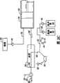
图1是表示血管造影术的注射系统的优选实施例的透视图。 Fig. 1 is a perspective view showing a preferred embodiment of an injection system for angiography. the
图2A-2G是表示图1的系统的操作的视图。 2A-2G are diagrams illustrating the operation of the system of FIG. 1 . the
图3是图1的注射系统的控制系统的电路框图。 FIG. 3 is an electrical block diagram of a control system of the injection system of FIG. 1 . the
图4表示注射系统的优选实施例的前面板控制和显示。 Figure 4 shows the front panel controls and displays of the preferred embodiment of the injection system. the
图5A和5B是图1的系统的遥控装置的侧视图和局部的顶透视图。 5A and 5B are side and partial top perspective views of the remote control of the system of FIG. 1 . the
图6是用脚操作的遥控装置的透视图。 Figure 6 is a perspective view of the foot operated remote control. the
图7A-7D表示在对比材料填充、空气清除和患者注射操作期间的进口止回阀和歧管的操作。 7A-7D illustrate the operation of the inlet check valve and manifold during contrast material fill, air purge, and patient injection operations. the
图8A-8C更详细地表示进口止回阀的操作。 Figures 8A-8C illustrate the operation of the inlet check valve in greater detail. the
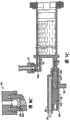
图9A和9B是表示血管造影术的注射系统的第二实施例的构造的透视图。 9A and 9B are perspective views showing the configuration of a second embodiment of the injection system for angiography. the
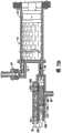
图10是表示图9所公开的系统的部分的安装构造的机械框图。 FIG. 10 is a mechanical block diagram showing a partial mounting configuration of the system disclosed in FIG. 9 . the
图11A和11B是图9和10的系统的控制系统和电气功能的电路框图。 11A and 11B are block circuit diagrams of the control system and electrical functions of the system of FIGS. 9 and 10 . the
图12是图11的控制系统的注射器电动机控制部分的电路框图。 FIG. 12 is a block circuit diagram of the syringe motor control portion of the control system of FIG. 11. FIG. the
图13是与图11的控制系统的蠕动泵电动机控制部分相关的安全电路的电路框图。 FIG. 13 is a block circuit diagram of a safety circuit associated with the peristaltic pump motor control portion of the control system of FIG. 11 . the
图14表示图11的系统的显示器的加电屏幕。 FIG. 14 shows a power-up screen of the display of the system of FIG. 11. FIG. the
图15表示图11的系统的显示器的后方校准屏幕。 FIG. 15 shows the rear calibration screen of the display of the system of FIG. 11. FIG. the
图16表示图11的系统的显示器的核对屏蔽。 FIG. 16 shows a checkout mask for a display of the system of FIG. 11. FIG. the
图17表示图11的系统的显示器的前方校准屏幕。 FIG. 17 shows the front calibration screen of the display of the system of FIG. 11 . the
图18表示图11的系统的显示器的第一启动指示屏幕。 FIG. 18 shows a first start-up indication screen of the display of the system of FIG. 11. FIG. the
图19表示图11的系统的显示器的第二启动指示屏幕。 FIG. 19 shows a second start-up indication screen of the display of the system of FIG. 11. FIG. the
图20表示图11的系统的显示器的第三启动指示屏幕。 FIG. 20 shows a third start-up indication screen of the display of the system of FIG. 11. FIG. the
图21表示图11的系统的显示器的第四启动指示屏幕。 FIG. 21 shows a fourth start-up indication screen of the display of the system of FIG. 11. FIG. the
图22表示图11的系统的显示器的准备填充灌注器屏幕。 FIG. 22 shows the ready to fill syringe screen of the display of the system of FIG. 11. FIG. the
图23表示图11的系统的显示器的灌注器填充提示屏幕。 FIG. 23 shows a syringe fill prompt screen of the display of the system of FIG. 11. FIG. the
图24表示图11的系统的显示器的清除提示屏幕。 FIG. 24 shows a clear prompt screen of the display of the system of FIG. 11. FIG. the
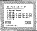
图25表示图11的系统的显示器的管线清除指示屏幕。 FIG. 25 shows a line purge indication screen of the display of the system of FIG. 11. FIG. the
图26表示图11的系统的显示器的清除管线提示屏幕。 FIG. 26 shows a purge line prompt screen of the display of the system of FIG. 11. FIG. the
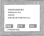
图27表示图11的系统的显示器的最终盐水冲洗指示屏幕。 FIG. 27 shows a final saline flush indication screen of the display of the system of FIG. 11. FIG. the
图28表示图11的系统的显示器的盐水冲洗提示屏幕。 FIG. 28 shows a saline flush prompt screen of the display of the system of FIG. 11. FIG. the
图29表示图11的系统的显示器的最终的启动屏幕。 FIG. 29 shows the final start-up screen of the display of the system of FIG. 11. FIG. the
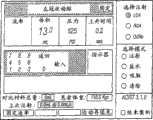
图30表示图11的系统的主显示屏幕。 FIG. 30 shows the main display screen of the system of FIG. 11. FIG. the
图31表示图30的主显示屏幕,其表示以注射模式操作。 Figure 31 shows the main display screen of Figure 30, shown operating in injection mode. the
图32表示图30的主显示屏幕,其表示当选择固定速率的操作模式时显示的键盘。 Figure 32 shows the main display screen of Figure 30 showing the keypad displayed when the fixed rate mode of operation is selected. the
图33表示图30的主显示屏幕,其表示当选择可变速率的操作模式时显示的键盘。 Figure 33 shows the main display screen of Figure 30 showing the keypad displayed when the variable rate mode of operation is selected. the
图34表示图30的主显示屏幕,其表示以手动清除模式操作。 FIG. 34 shows the main display screen of FIG. 30 showing operation in manual clear mode. the
图35表示图30的主显示屏幕,其表示以手动再填充模式操作。 Figure 35 shows the main display screen of Figure 30, shown operating in the manual refill mode. the
图36A-C表示用于流率极限的缺省注射参数值的比较图表,该流率极限由与患者体重有关的算法确定。 36A-C represent graphs comparing default injection parameter values for flow rate limits determined by an algorithm related to patient weight. the
图37A-C表示用于体积极限的缺省注射参数值的比较图表,该体积极限由与患者体重有关的本发明的算法确定。 Figures 37A-C represent graphs comparing default injection parameter values for the volume limit determined by the algorithm of the present invention in relation to patient weight. the
图38是示意性的流程图,其表示用于确定图36和37的与患者有关的缺省注射参数的程序。 FIG. 38 is a schematic flow diagram representing a procedure for determining the patient-dependent default injection parameters of FIGS. 36 and 37 . the
图39表示根据一个实施例的用户接口屏幕,其可显示在动力式注射系统(powered injection system)的控制面板上,从而为用户提供心脏手术类型或外围(非心脏)手术类型的选项。 Figure 39 illustrates a user interface screen that may be displayed on the control panel of a powered injection system to provide the user with the option of a cardiac surgery type or a peripheral (non-cardiac) surgery type, according to one embodiment. the
图40表示根据一个实施例的用户接口屏幕,其用于心脏手术类型。 Figure 40 illustrates a user interface screen for a cardiac surgery type, according to one embodiment. the
图41表示根据一个实施例的用户接口屏幕,其用于外围(非心脏)手术类型。 Figure 41 shows a user interface screen for a peripheral (non-cardiac) procedure type, according to one embodiment. the
图42是根据一个实施例的夹具的视图,该夹具可连接至患者的床台上。 Figure 42 is a view of a clamp attachable to a patient's table according to one embodiment. the
图43是根据一个实施例的可调节臂的视图,该可调节臂可联接至动力式注射系统的控制面板上。 Figure 43 is a view of an adjustable arm that can be coupled to a control panel of a power injection system, according to one embodiment. the
图44是夹具的一个实施例的视图,该夹具连接至床台的导轨上,并且还可连接至可调节臂上,诸如图43所示的夹具。 FIG. 44 is a view of one embodiment of a clamp that is attached to the rails of the bed platform and can also be attached to an adjustable arm, such as the clamp shown in FIG. 43 . the
图45是根据一个实施例的图43所示的可调节臂的视图,该可调 节臂联接至控制面板和床台的导轨上。 Figure 45 is a view of the adjustable arm shown in Figure 43 coupled to the control panel and rails of the bed platform, according to one embodiment. the
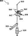
图46是根据一个实施例的可调节部件的视图,该可调节部件用于悬挂医用流体,诸如对比介质。 Figure 46 is a view of an adjustable member for suspending medical fluid, such as contrast media, according to one embodiment. the
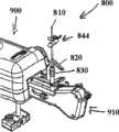
图47是动力式注射系统的视图,该动力式注射系统包括图46所示的可调节部件。 47 is a view of a power injection system including the adjustable components shown in FIG. 46 . the
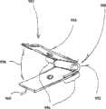
图48是根据另一个实施例的可调节部件的视图,该可调节部件也可与医用流体悬挂器一起使用。 Figure 48 is a view of an adjustable member, which may also be used with a medical fluid hanger, according to another embodiment. the
图49是根据一个实施例的动力式注射系统的视图,该动力式注射系统包括多个悬挂器和多个流体储器。 Figure 49 is an illustration of a power injection system including multiple hangers and multiple fluid reservoirs according to one embodiment. the
图50是医用流体悬挂器的另一个实施例的视图,该医用流体悬挂器可与动力式注射系统一起使用。 Figure 50 is a view of another embodiment of a medical fluid hanger that may be used with a powered injection system. the
图51是根据一个实施例的托盘的视图,该托盘可与动力式注射系统一起使用。 Figure 51 is a view of a tray that may be used with a power injection system, according to one embodiment. the
图52是根据一个实施例的图51所示的托盘的视图,该托盘联接至动力式注射系统的注射头上。 Figure 52 is a view of the tray shown in Figure 51 coupled to an injection head of a power injection system, according to one embodiment. the
具体实施方式Detailed ways
在本文的更详细描述之后将了解的是,本发明的各个实施例的原理可应用于自动注射系统的多种不同的物理构造。下文将总体描述一种这样的系统的示例。应了解的是,虽然将参考本发明的优选实施例描述(多个)具体的系统,但是本发明的原理不局限于用在所述的优选实施例中。参考附图,图1表示注射系统10,其用于在交互式的医师控制下将射线照相对比材料注射至血管内。系统10包括主控制台12,手持式遥控装置14,灌注器保持器16,灌注器本体18,灌注器柱塞20,射线照相材料储器(瓶子)22,单向阀24,歧管26,高压管28,导管30,患者药物端口32,三通旋塞34,T形连接器36,压力换能器38,旋塞40,管道42,蠕动泵44,盐水止回阀46,废物止回阀48,盐水袋50,废物袋52,和袋支承支架54。 As will be appreciated following the more detailed description herein, the principles of the various embodiments of the invention are applicable to a variety of different physical configurations of automatic injection systems. An example of one such system is generally described below. It should be appreciated that although specific system(s) will be described with reference to preferred embodiments of the invention, the principles of the invention are not limited to use in the described preferred embodiments. Referring to the drawings, Figure 1 illustrates an
控制台12容纳用于系统10的电气控制器,驱动活塞20和蠕动泵44的电动机。在控制台12的前表面上,用户接口55提供控制开关56和显示器58,用户可通过控制开关56和显示器58输入控制器设置并监控系统10的操作状态。控制台可以是独立式的,并且优选地构造为用于安装在运输车组件上。 Console 12 houses the electrical controls for
电能由适当的电源提供至系统的所有电气部件,该电源还提供与主电源的电气安全隔离。电源可位于控制台12内,但是电源优选地与控制台12分离地安装,安装在墙壁上或者安装在安装车上。 Electrical power is supplied to all electrical components of the system by a suitable power supply which also provides electrical safety isolation from the mains supply. The power supply may be located within the
遥控装置14通过电缆60连接至控制台12(虽然在其它实施例中,遥控装置14可通过无线连接进行连接,该无线连接诸如RF、红外光学或超声波联接)。在图1所示的实施例中,遥控装置14为手持式控制器,其包括分别为62和64的重置按钮开关和盐水按钮开关64,和流率控制杆或制动器66。通过按压制动器66,用户可为控制台12提供控制信号,以提供连续可变的注射速率。 The
灌注器保持器16从控制台12的左手侧突出。灌注器保持器16优选为透明材料,并且包括半圆柱形后壳68,半圆柱形前门70(其在图1中示出为处于打开位置),和储器保持器72。 A
灌注器18为透明的或半透明的塑料圆筒,其具有连接至控制台12的打开端74。灌注器18的封闭端76包括两个端口:上端口78和下端口80。
柱塞20可在灌注器本体18内移动。柱塞20连接至电动机并且由该电动机所驱动,该电动机位于控制台12内。 The
射线照相对比材料储器22通过单向止回阀24连接至上端口78上。将射线照相对比材料从储器22通过止回阀24和上端口78抽取至泵送室,该泵送室由灌注器本体18和柱塞20限定。止回阀24优选为加重式(weighted)单向阀,其允许空气从灌注器本体18流回至储器22内,但将不允许射线照相对比材料从灌注器本体18流动至储器22。这允许从系统中自动地清除空气,这将在下文进行更详细地描述。 The radiographic
灌注器本体18的下端口80连接至歧管26上。歧管26包括弹簧偏置的滑阀,其通常连接换能器/盐水端口82和患者端口84。当将要注射该射线照相对比材料时,射线照相材料的压力使滑阀改变状态,以便下端口80连接至患者端口84上。 The
高压管28为柔性管,其将患者端口84连接至导管30上。三通旋塞34位于管28的远端处。可旋转的路厄(luer)螺旋式连接器86连接至旋塞34上,并且与在导管30的近端处的路厄连接器88相配合。旋塞34或者阻塞管28和导管30之间的流动,允许该流动,或者将药物端口32连接至导管30上。
除通过导管30将射线照相材料注射至患者体内之外,系统10还允许执行其它相关的功能。当通过导管30将药物输送至患者时,用于输送患者药物的装置(未示出在图1中)可连接至药物端口32上。 In addition to injecting radiographic material into a patient through
当导管30在患者中处于适当位置并且不注射该射线照相对比材料时,压力换能器38通过流体柱监控血压,该流体柱从导管30,管28,患者端口84,歧管26,换能器/盐水端口82,管道90,T形连接器36,和管道92延伸。换能器38具有相关的旋塞40,其允许换能器38在校准期间暴露于大气压力,以及允许移除/排除夹带空气,因此可利用盐水冲洗换能器38的拱形腔室。 When
蠕动泵44通过盐水止回阀46,管道42,T形连接器36和管道90将盐水溶液从袋子50供应至盐水端口82。当操作该蠕动泵44以供应盐水溶液时,盐水溶液通过歧管26供应至患者端口84,并且然后通过管28供应至导管30。
蠕动泵44还以相反的方向操作,以将流体从导管30通过管28,歧管26,管道90,T形连接器36和管道42抽取至废物止回阀48,并且然后抽取至废物收集袋52内。
在本发明的优选实施例中,灌注器本体18,歧管26,管28,导管30,T形连接器36,管道42,止回阀46和48,袋子50和52,和管道90和92都为一次性物品。每当对新的患者执行血管造影术时, 他们必须安装在系统10中。一旦系统10在安装了所有的一次性物品的情况下做好准备,门70为关闭的,以及灌注器本体18填充有对比材料并且清除了空气,用户(通常为医师)就将安全参数输入系统10内,该安全参数将应用于射线照相对比材料的注射。这些安全参数通常包括在任何一次注射期间待注射的射线照相对比材料的最大量,注射的最大流率,在灌注器本体18内产生的最大压力,和注射的最大上升时间或加速度。为了注射对比材料,用户通过按压制动器66操作遥控装置14。在预设的安全参数内,随着制动器66的作用力或行程的增加,系统10增加注射的流率。 In the preferred embodiment of the invention,
通常,基于利用荧光透视法或其它成像方法连续地观察进入正在注射的组织内的对比材料流出,用户将测量所注射的对比材料的量和速率。系统10允许用户使对比材料注射适合患者的需要,从而改善手术的质量,增加安全性,以及减小执行荧光透视检查所需的对比材料的量。 Typically, the user will measure the amount and rate of the injected contrast material based on continuously observing the efflux of the contrast material into the tissue being injected using fluoroscopy or other imaging methods.
图2A-2G是表示在系统10的七种不同操作期间的流体流动路径的视图。这些操作为对比材料填充(图2A),空气清除(图2B),患者注射(图2C),患者压力(图2D),盐水冲洗(图2E),吸取废物(图2F),和医治患者(图2G)。 2A-2G are diagrams illustrating fluid flow paths during seven different operations of the
示于图2A中的对比材料填充操作包括从储器(对比介质供应源)22向灌注器本体18填充射线照相对比材料。对比材料填充操作在系统10的初始准备期间执行,并且可在灌注器本体18以少的射线照相对比材料运行的任何时候在系统10的操作期间重复执行。 The contrast material filling operation shown in FIG. 2A involves filling the
在系统10的初始准备期间,首先将柱塞20驱动至其最远的前方位置,该最远的前方位置在灌注器本体18的封闭端76附近。这将位于灌注器本体18内的大部分空气排出至大气内。 During initial preparation of the
然后将柱塞20缩回,这在灌注器本体18内形成真空,该真空将对比材料从储器22通过止回阀24和通过上端口78抽取至灌注器本体18内。 The
对比材料填充操作通常将使一些空气抽取至灌注器本体18内或考残留在灌注器本体18内。当然,重要的是防止空气通过导管30注射至患者体内。这就是图2B所示的空气清除操作的目的。此外,两个端口处于不同高度的布置允许在防止注射中的空气泡方面的更大的安全性。 The contrast filling operation will typically cause some air to be drawn into or trapped within the
在空气清除操作期间,柱塞20向前移动,以排出在灌注器本体18内的夹带空气。比对比材料轻的空气聚集在灌注器本体18的顶部附近。当柱塞20向前移动时,空气从灌注器本体18通过上端口78和单向阀24排出。在图2B所示的实施例中,单向阀24为加重式单向阀,其允许射线照相对比材料从储器22流动至上端口78,但不允许射线照相对比材料沿相反的方向从上端口78流动至储器22。然而,阀门24允许空气从端口78流动至储器22。一旦射线照相对比材料开始通过上端口78从灌注器本体18流出至阀门24,阀门24就关闭以防止朝向储器22的任何的进一步流动。 During an air purge operation, the
在可选实施例中,阀门24还可为在控制台12内的电路的控制下操作的螺线管促动的或电动机驱动的阀门。在每一个实例中,阀门24能够承受其在注射操作期间将经受的较高的压力。优选地,阀门24能够承受直至大约1200磅/平方英寸的静流体压力。 In alternative embodiments,
图2C表示患者注射操作。柱塞20在用户的交互式控制下向前移动,该用户控制遥控装置14的制动器66。柱塞20的移动产生液压压力,以迫使对比材料通过下端口80以及通过歧管26和高压管28离开灌注器本体18进入导管30内。如图2C所示,在患者注射操作期间,灌注器下端口80和患者端口84相连接,用于流体流动。 Figure 2C shows a patient injection procedure. The
歧管26包括控制患者端口84和灌注器下端口80或换能器/盐水端口82之间的流体连接的路由选择的阀门。在本发明的一个实施例中,歧管26包括滑阀,该滑阀为弹簧偏置的,以便患者端口84通常连接至换能器/盐水端口82(如图2A和2B所示)。当灌注器下端口80处的压力随着柱塞20的向前移动而形成时,克服作用于滑阀的偏置 力,以便灌注器下端口80连接至患者端口84,并且分离该换能器/盐水端口82,歧管26内的阀门防止压力换能器38暴露于由患者注射操作所产生的高压。
响应于增大从灌注器下端口80施加在滑阀上的压力,滑阀在患者注射操作期间自动地打开。当在每个患者注射操作的结束时柱塞20的缩回施加轻微的真空时,滑阀关闭并返回至其原始位置,从而允许患者端口84连接至换能器38。 In response to increasing pressure on the spool valve from the syringe
在可选实施例中,在歧管26内的阀门是机电的或电动机驱动的阀门,其在适当的时间促动,以将灌注器下端口80或换能器/盐水端口82连接至患者端口84。该促动机构由控制台12控制。再次,在该可选实施例中,阀门防止压力换能器38暴露于高压。 In alternative embodiments, the valves within
图2D表示患者压力操作。系统10允许读取通过导管30监测的患者的血压。除在患者注射,盐水冲洗,和废物吸取操作期间之外的任何时间,可通过使用压力换能器38监测患者血压。通过手动地打开旋塞40和关闭旋塞34以将压力换能器38暴露于大气压力,可使由压力换能器38进行的压力读取标准化。 Figure 2D shows patient pressure operation.
在图2E所示的盐水冲洗操作期间,盐水溶液用于冲洗所有的内部管线,压力换能器腔室38,管28,和导管30。如图2E所示,蠕动泵44以如下方向操作,即该方向使盐水溶液从袋子50通过止回阀46以及通过管道42抽取至盐水端口82。歧管26将盐水端口82连接至患者端口84,以便将盐水溶液泵送出患者端口84,并且通过管28和导管30。 During the saline flush operation shown in FIG. 2E , a saline solution is used to flush all internal lines,
在吸取废物操作期间,患者端口84再次连接至盐水端口82。在该操作期间,蠕动泵44以与其在盐水冲洗操作期间的旋转相反的方向操作。因此,患者流体从患者端口84吸取至盐水端口82,然后通过管道42和止回阀48吸取至废物收集袋52内。蠕动泵44作为如下的阀门,即该阀门与止回阀46和48一起捏夹/闭塞管道42,以及防止回流至盐水容器50和废物容器52或防止从盐水容器50和废物容 器52回流。
当导管30在患者体内处于适当位置时,可合乎期望地供应患者药物。通过提供患者药物端口32,系统10允许供应患者药物。如图2G所示,当旋塞34打开时,连接至端口32的药物源将连接至患者端口84,并因此连接至导管30。在医治患者操作期间,蠕动泵44和柱塞20为不移动的。 When
图3是与上述的血管造影术注射系统一起使用的控制系统的电路框图。图3的电气控制系统包括单个数字计算机100,其从通过接口102从遥控装置14和前面板控制器56接收输入信号,并且为显示器58提供信号以显示操作数据、警报、状态信息和操作者提示。随后的优选实施例将描述改进的电气控制系统;然而,在此将描述单个计算机系统,以完成血管造影术注射系统的功能描述,该血管造影术注射系统结合上述的血管造影术注射系统10的部件。 Fig. 3 is an electrical block diagram of a control system for use with the angiography injection system described above. The electrical control system of FIG. 3 includes a single
计算机100通过电动机驱动电路控制柱塞20的运动,该电动机驱动电路包括电动机104,电动机放大器106,转速计108,电位计110,整流器112,压力传感的测压元件114,和A/D转换器116。 The
响应于来自于计算机100的控制电压、Fwd/Rev和/制动信号,以及通过整流器112的来自于转速计108的速度反馈信号,电动机放大器106提供驱动1信号至电动机104。转速计108和电位计110的输出作为速度监控信号和位置监控信号通过A/D转换器116提供给计算机100。这允许计算机100核对电动机速度、电动机方向和位置(体积为计算值)。
压力传感器114检测电动机电流或柱塞力,以便测量施加到灌注器本体18内的射线照相对比材料的压力。该压力监控信号通过A/D转换器116和接口102提供至计算机100。
在计算机100的控制下,通过泵用电动机120、电动机驱动器122和光学编码器124驱动蠕动泵44。计算机100提供盐水(向前)驱动信号和废物(后退)驱动信号至电动机驱动器122,以沿用于盐水冲洗的前 进方向和用于废物吸取的后退方向操作泵用电动机120。光学编码器124提供速度方向监控信号至接口102,该接口102指示泵用电动机120的速度和旋转方向。 The
图3表示控制系统的实施例,其中阀门电动机130用于促动阀门,诸如单向阀24和歧管26内的阀门。在该实施例中,计算机100通过电动机驱动器132控制阀门电动机130,并且通过来自电位计134的位置监控反馈信号监控位置。在该具体实施例中,阀门电动机130是步进电动机。 FIG. 3 shows an embodiment of a control system in which
计算机100基于来自温度传感器140的温度监控信号监控对比材料的温度。温度传感器140优选地定位在灌注器本体18的附近。如果由温度传感器140检测的温度太高,则计算机100将停止电动机104的操作,以中断患者注射。如果温度太低,则计算机100提供/温度使能驱动信号至加热器驱动器150,其为加热器152提供能量。在一个优选实施例中,加热器152是电阻膜加热器,其邻近于灌注器本体18地定位在灌注器保持器116内。 The
计算机100还从对比材料瓶传感器160、前进极限传感器162、后退极限传感器164、灌注器缺失传感器166、腔室打开传感器168、无对比材料气泡检测器170和管线内空气泡检测器172接收反馈信号。
对比材料瓶传感器160是位于储器保持器72内的微型开关。来自传感器160的对比材料瓶存在信号的状态指示储器22是否在保持器72内处于适当位置。如果储器22不存在,则计算机100将停止填充操作。 The
前进极限传感器162和后退极限传感器164检测柱塞20的末端极限位置。当柱塞20到达其前进极限位置时,不允许柱塞20的进一步的向前移动。相似地,当后退极限传感器164指示柱塞20达到其后退极限位置时,不允许进一步的后退运动。 The
灌注器缺失传感器166是微型开关或红外发射器/检测器,其指示 灌注器本体18何时不在灌注器保持器16内处于适当位置。如果灌注器本体18不处于适当位置,则除柱塞20可移动至其后退极限位置(即,返回至零)以外,停止所有的移动功能。 The
腔室打开传感器168是微型开关或红外发射器/检测器,其检测灌注器保持器16的门70何时打开。当来自传感器168的信号指示门70打开时,停止所有的移动功能。只有当门70被关闭和锁定时,才可允许任何的移动。当门70指示为关闭的并且传感器166指示灌注器本体18处于适当位置时,可进行系统10的其它正常的功能。 The chamber
气泡检测器170定位在储器22和上端口78之间,并且优选为检测空气泡的红外发射器/检测器。如果在填充操作期间在储器22和上端口78之间的流动路径中检测到空气泡,则停止填充操作,直到连接新的储器。
气泡检测器172定位成检测高压管线28中的空气泡。气泡检测器优选为红外发射器/检测器类型的气泡检测器。无论流体是来自蠕动泵44的盐水溶液或者是来自灌注器本体18的对比材料,在高压管线28中检测的任何空气泡将停止所有的流体排出功能。
图3的控制系统还包括通过由计算机100控制的继电器180提供控制信号至x射线设备的能力。此外,计算机100从血压换能器38和从心电图仪(ECG)系统接收数据,该心电图仪系统与注射系统10分离。压力和ECG信号通过信号调节器和A/D转换器190接收,并且传递至计算机100。在一个优选实施例中,ECG信号由计算机100使用,以使电动机104的操作(因此患者注射操作)与心跳同步。 The control system of FIG. 3 also includes the ability to provide control signals to the x-ray device through a
血液流动至心脏主要在心脏舒张期(当心脏处于收缩之间时)进行。对比材料的连续注射导致在心脏收缩期间(在收缩期间)对比材料溢出至主动脉内。通过主要在心脏舒张期间的注射,可减少对比材料用量,而不影响将对比材料注射至冠状动脉内的完整性。 Blood flow to the heart occurs primarily during diastole (when the heart is between contractions). The continuous injection of contrast material results in an overflow of contrast material into the aorta during systole (during systole). By injecting primarily during diastole, the amount of contrast material can be reduced without compromising the integrity of the injection of contrast material into the coronary arteries. the
在优选实施例中,射线照相对比材料的注射与冠状动脉血流同步。利用心电图(ECG)电信号、动脉血压波形分析或基于心率的其它 计时(timing),确定心脏收缩和心脏舒张的时间周期。通过控制电动机104的速度,以及因此控制柱塞20的移动速度,在心脏收缩期间中断对比材料的注射,这将在该时间期间减少或者停止对比材料注射。结合遥控装置14,操作者可改变对比材料注射至冠状动脉内的速率,同时计算机100将对比材料注射的周期调节为心动周期。 In a preferred embodiment, the injection of the radiographic contrast material is synchronized with coronary blood flow. The systolic and diastolic time periods are determined using electrocardiogram (ECG) electrical signals, arterial blood pressure waveform analysis, or other timing based on heart rate. By controlling the speed of the
移动的对比材料的惯性力以及容器和管道的膨胀可在柱塞20在灌注器本体18内的移动和对比材料离开导管30进入患者体内的移动之间产生相位延迟,该容器和管道保持该对比材料并将对比材料传递至患者。为了适应柱塞20移动和对比材料排出至患者体内之间的相位延迟,可通过控制面板54输入可变的时间偏移,使得心动周期的计时由选定的时间所抵销。由于相位延迟的大小可能取决于心率的频率,故基于在对比材料的注射期间的瞬时心率,计算机100内的算法连续地且自动地调节时间偏移的大小。 The inertial forces of the moving contrast material and the expansion of the container and tubing that maintain the contrast can create a phase delay between the movement of the
图4显示控制面板54的一个实施例,其表示本发明的一个实施例的前面板控制开关56和显示器58。前面板控制开关56包括准备/填充/结束开关200,清除开关202,吸取开关204,盐水开关206,使能确认开关208,注射体积极限开关210a和210b,注射流率极限开关212a和212b,注射压力极限开关214a和214b,上升时间开关216a和216b,确认开关218,注射范围拨动开关220,大量注射确认开关222,和停止开关224。 FIG. 4 shows one embodiment of a
准备/填充/结束开关200是瞬时按钮开关。当第一次促动该开关200时,将告知用户将灌注器18放置在灌注器保持器16中。当灌注器18已经放置在灌注器保持器16中时(这通过传感器166告知计算机100),将指示用户关闭和锁定腔室(即,关闭门70)。柱塞20移动至其完全前进的位置,从而排出灌注器内的所有空气。然后,显示器58指示操作者应该连接对比材料储器22。一旦将对比材料储器22放置在适当位置,就要求操作者压下确认开关218,此时柱塞20将以设定的速率(优选为相当于10毫升/秒的流率)缩回至最大的灌注器体积。如 果实际的速度(其从A/D转换器116通过反馈告知计算机100)大于设定的速度,系统10将停止。 Ready/Fill/
一旦柱塞20处于其最后方的位置,促动该电动机104以向前移动柱塞20,从而清除所有的空气泡。压力传感器114提供对单向阀24何时关闭以及何时在灌注器本体18内开始产生压力的指示。一旦该清除完成,重新设定注射的总体积和注射计数器的次数。 Once the
开关200的促动还允许柱塞20从灌注器本体18缩回和脱离。 Actuation of the
清除开关202是防护的瞬时按钮开关。当促动时,清除开关202使柱塞20向前移动,以通过上端口78排出空气。当达到灌注器18内的预定压力时,限制和停止柱塞20的向前移动。这由压力传感器114进行检测。由清除开关202启动的清除操作将排出灌注器20内的空气。通过压下并保持清除开关202连续地接通,用户还可使用清除开关202通过患者端口84清除流体。
吸取开关204是瞬时按钮开关,其使计算机100促动蠕动泵44的泵用电动机120。操作该泵用电动机120,以便以设定速度吸取导管30,其中吸取的流体收集在废物袋52中。所有其它的移动功能在吸取期间停止。如果电动机120的实际速度大于设定速度,则计算机100将停止电动机120。 The
盐水开关206是可选的工作开关。响应于将盐水开关206推动为接通的,促动该泵用电动机120,并且来自袋子50的盐水溶液以设定速度引入至歧管26和导管30内。如果在10秒内没有第二次推动盐水开关206以停止盐水溶液的流动,则计算机100自动地停止泵用电动机120。如果超时(time-out),则在开始任何进一步的动作之前,必须将盐水开关206重新设定至其初始状态。 The
使能确认开关208是瞬时按钮开关。在系统检测到除极限以外的在注射结束时的停止功能之后,必须在促动确认开关218和开始任何进一步的功能之前促动使能确认开关208。 Enable
推动注射体积极限键210a和210b,以增大或减小系统将在任何 一次注射期间注射的最大注射体积。键210a增大最大体积值,键210b减小最大体积值。一旦已经设定最大注射体积极限,如果测量的体积达到设定值,则计算机100将停止电动机104并且将不会重新开始,直到压下确认开关218。如果已经选择大量注射(即,大于10毫升),则在开始大量注射以前必须重新设定确认开关218和大量注射确认开关220。 Push the injection
注射流率极限键212a和212b允许医师选择系统可在任何一次注射期间达到的最大流率。如果测量的速率(其由来自转速计108和电位计110的反馈信号所确定)达到设定值,则计算机100将控制电动机104,以将流率限制至设定值。 Injection flow
注射压力极限键214a和214b允许医师选择系统可在任何一次注射期间达到的最大压力。如果由压力传感器114确定的测量的压力达到设定值,则计算机100将控制电动机104,以将压力限制至注射压力极限。因此,还将限制注射速率。 Injection
上升时间键216a和216b允许医师选择在任何一次注射期间系统在改变流率时将允许的上升时间。计算机100控制电动机104,以将上升时间限制至设定值。
在可选实施例中,键210a-210b,212a-212b,214a-214b,和216a-216b可由用于选择数值的其它装置所代替。这些装置包括选择器标度盘,数字键盘,和触摸屏。 In alternative embodiments, keys 210a-210b, 212a-212b, 214a-214b, and 216a-216b may be replaced by other means for selecting values. These devices include selector dials, numeric keypads, and touch screens. the
确认开关218是瞬时按钮开关,其对功能和硬件传感器进行重置。响应于促动确认开关218,计算机100控制显示器58,以要求操作者确认已经选择正确的功能。确认开关218的促动将状态设定为就绪。
注射范围开关220是拨动开关。根据开关220是否处于“少量”位置或“大量”位置,开关220为下一次注射选择大的或小的注射体积范围。
大量注射确认开关222是瞬时按钮开关。当通过注射范围开关220选择大量注射范围时,必须促动大量注射确认按钮222,以使能该确 认开关218。在每次注射之前必须促动确认开关218。在大量体积注射时,用户需要核实通过首先促动大量注射确认开关222以及然后促动确认开关218所选择的体积。 Bulk
停止开关224是瞬时按钮开关。当推动停止开关224时,停止所有的功能。显示器58保持为工作的。 The
显示面板58包括准备显示器250,状态显示器252,警报显示器254,极限显示器256,总注射次数显示器260,总注射体积显示器262,流率显示器264,注射体积显示器266,注射体积极限显示器268,注射速率极限显示器270,压力极限显示器272,上升时间最小值显示器274,大量注射显示器276,和实时时钟显示器278。 The
准备显示器250包括当操作者经历准备程序时显示的一系列消息。如前所述,通过准备开关200的促动,开始显示该准备显示器250中的消息。 The
状态显示器252提供多种不同的操作条件中的一种的闪烁指示。在图4所示的实施例中,可显示的这些状态条件包括“就绪”,“准备”,“注射”,“填充”,“冲洗”,和“吸取”。 Status display 252 provides a blinking indication of one of a number of different operating conditions. In the embodiment shown in FIG. 4, the status conditions that may be displayed include "ready", "ready", "inject", "fill", "flush", and "aspirate". the
警报显示器254和极限显示器256告知操作者如下的状况,即系统10达到临界的控制参数并将停止操作,或者达到上极限或下极限并将以限制的方式继续运行,或达到上极限或下极限并将继续操作。
总注射次数显示器260显示为当前的患者案例执行的总注射次数(累加的)。在当前的患者案例期间注射的累加的总体积由总体积显示器262显示。 The total number of injections display 260 shows the total number of injections (cumulative) performed for the current patient case. The accumulated total volume injected during the current patient case is displayed by the total volume display 262 . the
显示器264和266提供有关当前注射或最近注射的信息。显示器264显示在注射期间对患者的实时流率的数字值。一旦完成注射,显示在显示器264上的值表示在该注射期间所达到的最高流速。显示器266显示在最近注射期间所注射的体积的数字值。
显示器268显示由开关210a和210b的操作所选择的最大注射体积的数字值。相似地,显示器270显示由开关212a和212b所选择的 系统将允许的最大流率的数字值。
显示器272显示允许系统在灌注器18中产生的最大压力的数字值。压力极限由开关214a和214b所选择。 Display 272 shows a numerical value for the maximum pressure the system is allowed to generate in
显示器274显示在改变流率时系统将允许的最小上升时间。最小上升时间通过开关216a和216b所选择。 Display 274 shows the minimum rise time the system will allow when changing the flow rate. The minimum rise time is selected by
当操作者选择大量注射等级时,大量注射显示器276提供明显指示。 The
实时时钟显示器278以时、分和秒显示当前时间。 The real
图5A和5B显示遥控装置14的一个实施例,该遥控装置14包括主壳体300,该主壳体300设计为符合用户的手。制动器66可相对于壳体300移动,制动器66的位置产生作为制动器位置之函数的命令信号。在一个实施例中,制动器66联接至壳体300内的电位计。命令信号控制注射流率或速度。该流率与制动器位置成正比。 Figures 5A and 5B show one embodiment of a
重置开关62是瞬时按钮开关,其功能与确认开关218的功能相同。作为备选,重置开关62也可标记为“确认”。
遥控装置14上的盐水开关64是交替动作的按钮开关,推动该盐水开关64以导通,再次推动该盐水开关64以关断。盐水开关62的功能与前面板54上的盐水开关206的功能相同。 The
如本发明的另一个实施例所示,使用采用脚踏板形式的备选的遥控装置14′代替图1以及图5A和5B所示的手持式遥控装置14。脚踏板遥控装置14′包括用于提供命令信号的用脚操作的速度踏板或制动器66′,以及重置开关或确认开关62′和盐水开关64′。盖子310和312保护开关62′和64′,以便他们只能由手促动,而不能由脚意外地促动。脚踏板遥控装置14′通过电缆60′连接至控制台12,但是可以可选地由无线电联接所连接。 As shown in another embodiment of the present invention, an alternative remote control device 14' in the form of a foot pedal is used instead of the handheld
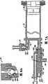
图7A-7D和图8A-8C表示在对比材料填充、空气清除和患者注射操作期间单向阀24和歧管26的结构和操作。 7A-7D and 8A-8C illustrate the structure and operation of the one-
图7A和8A表示在对比材料填充操作期间的单向阀或止回阀24、 歧管26、灌注器本体18和柱塞20。单向阀24的进口止回阀包括重球350,其在图7A和7B中在阀室352内定位在其下安置位置处。通过柱塞20的向后移动,将对比材料抽取至灌注器本体18内。对比材料围绕球350通过通路354流动,并且流动至上端口78内。 7A and 8A show the one-way or
歧管26包括弹簧加载的滑阀360,其包括滑阀本体362,轴364,O形环366、368和370,偏置弹簧372,和保持器374。如图7A所示,在对比材料填充操作期间,偏置弹簧372将滑阀本体362朝向灌注器本体18推动至其最右方位置。在该位置中,滑阀本体362阻塞灌注器本体18的下端口80,同时通过斜通路376将换能器盐水端口82连接至患者端口84。一方面O形环366和368,另一方面O形环370定位在斜通路376的相对侧上,以提供流体密封。
图7B和8B表示空气清除操作。灌注器本体18填充有对比流体,但是也包括夹带空气。向前驱动柱塞20,以迫使空气通过上端口78以及通过止回阀24离开灌注器本体18。空气的作用力可使球350在止回阀20中略微地升高。然而,球350足够地重,使得迫使离开灌注器本体18并且向后朝向储器22的空气不能将球350提升至其最高的安置位置,在该最高的安置,球350将阻塞空气流出灌注器本体18。 7B and 8B illustrate the air purge operation. The
在空气清除操作期间,滑阀360处于与图7A相同的位置。斜通路376连接换能器盐水端口82和患者端口84。因此,在空气清除(以及对比材料填充)操作期间,可通过压力换能器38监控压力。 During air purge operation,
图7C和8C表示在空气清除操作结束时和在患者注射操作开始时的歧管26和止回阀24的状态。 7C and 8C show the status of the manifold 26 and
在图7C中,所有的空气从灌注器本体18中排出。球350可浮在射线照相对比材料上,以便当移除所有的空气以及射线照相对比材料开始流出灌注器本体18并且通过上端口78流动至阀室352时,球350向上移动至其上安置位置。球350阻塞射线照相对比材料的任何继续的向上流动,如图7C和8C所示。 In FIG. 7C , all the air is expelled from the
在图7C所示的状态下,灌注器本体18内的压力,尤其是下端口 80中的压力尚未达到克服弹簧372的偏置力的水平。因此,滑阀本体362尚未移动至左侧,斜通路376继续连接换能器盐水端口82和患者端口84。 In the state shown in FIG. 7C , the pressure in the
图7D表示患者注射操作。柱塞20向前移动,进口止回阀24被关闭。下端口80处的压力变得足够大,从而克服弹簧372的偏置力。驱动滑阀本体362至左侧,以便下端口80连接至患者端口84。同时,滑阀本体362阻塞换能器/盐水端口82。 Figure 7D shows a patient injection procedure. The
由于滑阀360的操作,由柱塞20和灌注器本体18的移动所产生高压直接连接至患者端口84,而盐水端口82和压力换能器38免于高压。用于促动的压力可为可变的,并且可在制造之后通过增大或减小灌注器预载进行确定。 Due to the operation of
本领域技术人员将了解的是,可配置通用血管造影术注射系统10的其它构造。例如,可采用引用的血管造影术注射系统的备选灌注器和安装系统部分,以代替和/或修改前述的血管造影术注射系统,该引用的血管造影术注射系统描述在名称为“Dual Port Syringe”的美国专利No.6,099,502中(通过引用而结合于本发明中)。此外,本领域技术人员将认识到的是,可采用其它改进,诸如对组件的歧管部分的改进,以及可采用遥控装置14的其它构造,该歧管部分的改进例如在名称为“Angiographic Injector System with Automatic High/Low PressureSwitching”美国专利No.6,221,045(通过引用而结合于本发明中)中进行了描述。遥控装置组件的多个备选构造在该引用申请和名称为“Pneumatic Controller-and Method”的美国专利No.5,916,165以及名称为“Hand-Held Pneumatic Control Device”的美国专利No.D404,717中进行了描述,所有这些美国专利都通过引用而结合于本发明中。 Those skilled in the art will appreciate that other configurations of the universal
前述附图的血管造影术注射系统的可选实施例构造在图9a和9b中以10′总体表示。在图9所示的实施例中,重新布置血管造影术注射系统10的一些部件的物理位置,用于便于使用该系统。例如,第一所述实施例的用户接口54、控制开关56和显示器58合并成单个控制 面板400。在所示的第二实施例中,控制面板400安装至在旋转底座上的控制台或注射头12′,该旋转底座可由用户分离和重新连接,用于最佳的布置。图9构造的机械示意图示于图10中。参考图9和10,电源59′电路示出为与控制台12′分离地机械安装。控制台和电源安装至总体表示为402的车上,该车包括用于容易移动的车轮,并且优选地设计为以便在以其预定方法使用时提供稳定性以及阻止倾斜。该车能够使控制台和电源组件快速地联接和分离,用于允许控制台和电源连接(dock)至床或装备有配合的连接装置的其它静止装置。参考图10,手动控制器14′示出为操作地连接至控制面板400,蠕动泵组件44′表示为机械地安装至控制台12′上。用于保持灌注器和相关部件的组件由称为“安装腔室”404的功能块总体表示,该灌注器和相关部件已经在前文中参考本发明的第一实施例描述。称为“一次性”物品的前述那些部件(即:灌注器,灌注器本体内的活塞,对比材料阀门(contrast valve),患者歧管,对比材料刺针和患者血压端口)由功能块406总体表示。 An alternative embodiment configuration of the angiography injection system of the preceding figures is indicated generally at 10' in Figures 9a and 9b. In the embodiment shown in FIG. 9, the physical location of some components of
用于血管造影术注射系统10′的第二优选控制构造的电气功能框图示于图11中。多个附图(图11a和图11b)共同包括血管造影术注射系统10′的电气控制网络。为了方便描述图11的网络,前文用于第一实施例的相应电气部件的标号将不必重复用于描述图11的相似功能的电气部件。参考图11,控制系统包括两个分离的计算机系统,每个计算机系统具有用于监测和控制注射系统的功能的智能。与前述实施例相同,计算机系统通常从控制面板400接收输入信号,并且提供信号以显示数据、警报、状态信息和操作员提示。在优选实施例中,计算机系统包括两个微型计算机。总体表示为410的PC处理器作为控制系统的主处理器,总体表示为412的嵌入式处理器作为从处理器。通常,主处理器指示嵌入式处理器执行命令,但是两个处理器都监控所采取的动作。为了安全,两个处理器都用作独立的动作监控器。诸如注射器电动机移动和蠕动泵电动机移动的关键功能由两个微型计算机监控。在优选实施例中,PC处理器410具有386DOS中央处理 单元,嵌入式核心处理器412具有HC16位中央处理单元。应了解的是,在本发明的精神和目的内,可使用其它类型的微处理器。 An electrical functional block diagram of a second preferred control configuration for angiography injection system 10' is shown in FIG. The various figures (Figs. 11a and 11b) collectively comprise the electrical control network of the angiography injection system 10'. For convenience in describing the network of FIG. 11 , the reference numerals previously used for corresponding electrical components of the first embodiment will not necessarily be repeated for describing similarly functioning electrical components of FIG. 11 . Referring to Figure 11, the control system comprises two separate computer systems, each with intelligence for monitoring and controlling the functions of the injection system. As with the previous embodiments, the computer system typically receives input signals from the
参考图11,应注意的是,PC处理器410利用第一通信总线414与整个系统内的电气部件通信,嵌入式核心处理器412利用第二通信总线416与整个系统内的电路通信。两个处理器利用他们各自的总线和总体表示为417和418的成对的通信寄存器彼此相通信。通用的“监示器/电源故障/重置”功能由功能块419表示,ECG所获得的信息可由功能块420基于先进先出的原理进行采集,用于由两个微处理器进行处理。通常,系统的多种电气功能块和两条总线414和416之间的通讯类型由与相应的电气功能块有关的图11的单独的信号流路所表示,以及由那些信号流路内的信号流标记所表示。 Referring to FIG. 11 , it should be noted that the
参考图11,与安装腔室404有关的多种电气功能和检测功能包括:称为“腔室关闭”(422)的传感器,其指示用于将一次性灌注器装入安装腔室内的前装载腔室门何时关闭;由“对比材料为空的”(423)表示的对比材料瓶传感器,其位于瓶保持器内并且指示流体是否存在于瓶中;两个阀门传感器,其表示为“上&下阀门传感器”(424),并且由计算机所使用以确定患者歧管阀门和对比材料阀门的状态;电荧光的后灯,其由“EL后灯”(425)表示,并且便于手动地检测灌注器和一次性物品内的气泡;加热元件,其由“对比材料加热器”(426)表示,并且在灌注器本体附近位于灌注器保持器内;成对的温度传感器,其由“RTD温度传感器”(427)表示,并且定位在灌注器本体附近,用于提供信号以控制对比材料加热器,从而将对比材料维持在相对恒定的温度;和空气柱检测传感器,其由“气泡检测”(428)表示,并且定位为以便检测高压管线中的空气,以及针对任何的气泡或空气柱监测泵送至患者的流体。如图11所示,除了EL背光425之外,在安装腔室中的每个传感器与两个处理器相通信。 Referring to Figure 11, various electrical and detection functions related to the mounting chamber 404 include: a sensor called "Chamber Closed" (422), which indicates the front load when the chamber door is closed; a contrast vial sensor indicated by "Contrast Empty" (423), which is located within the vial holder and indicates whether fluid is present in the vial; two valve sensors, denoted "Up & Lower Valve Sensor" (424), and is used by the computer to determine the status of the patient manifold valve and contrast material valve; the electroluminescent backlight, which is represented by the "EL Backlight" (425), and facilitates manual detection Air bubbles within the syringe and disposable; heating element, represented by "Comparative Material Heater" (426), and located within the syringe holder near the body of the syringe; paired temperature sensors, represented by "RTD Temperature sensor" (427), and is positioned near the syringe body for providing a signal to control the contrast material heater, thereby maintaining the contrast material at a relatively constant temperature; and the air column detection sensor, which is detected by the "bubble detection" ( 428) and is positioned so as to detect air in the high pressure line and monitor the fluid being pumped to the patient for any air bubbles or columns of air. As shown in FIG. 11 , with the exception of the
通常,控制面板400包括臂灯430,扬声器431,触摸屏432,显示器433和紧急开关434。当注射器准备执行注射时臂灯430发光。 扬声器431为可选的特征,其可为用户提供听觉的接口通信。在优选实施例中,显示器433为液晶(LCD)面板,其用于显示系统的操作状态。触摸屏432重叠在LCD面板上,并且由用户用于控制系统,下文将对其进行更详细地描述。控制面板的所有功能与PC处理器410直接通信。紧急开关434与两条通信总线414和416以及下文所述的断路继电器和注射器电动机固态继电器直接通信。 Generally, the
手动控制功能块14′包括遥控的手动控制单元的电路功能。如前所述,手动控制器为用于以如下方式控制血管造影术注射泵的装置,该方式使得当由用户促动时该装置输出与手动控制装置的位移成比例的电信号。控制器为与图11所示的两个微处理器通信的无源机电装置。手动控制器包括成对的密封的接触(on-contact)传感器,其可遥控地确定目标的位置,并且可用于确定控制器的可手动部分的工作的移动距离和位移。该传感器由两个功能块表示,该两个功能块表示为“模拟霍耳效应”(440)和“数字霍耳效应挤压(squeeze)”(441)。盐水重置功能由“盐水重置按钮”(442)表示,表示为“控制类型和连接”(443)的功能块通过手动控制器为微处理器提供关于系统是否正用于执行“固定速率”或“变化速率”注射的设置指示。在变化速率的操作模式下,允许操作者利用手动控制器改变瞬时注射速率,直至预定的最大流率。在固定的操作模式下,当操作者挤压手动控制器的促动器时,控制系统将通过以预定的固定速率注射对比材料来进行响应,该预定的固定速率在注射手术之前已经输入控制系统内。 The manual control function block 14' comprises the circuit functions of the remote manual control unit. As previously mentioned, a manual controller is a device for controlling an angiography syringe pump in such a manner that when actuated by a user, the device outputs an electrical signal proportional to the displacement of the manual control device. The controller is a passive electromechanical device that communicates with the two microprocessors shown in FIG. 11 . The manual controller includes a pair of sealed on-contact sensors that can remotely determine the position of the target and can be used to determine the distance and displacement of the working movement of the manually operable portion of the controller. The sensor is represented by two functional blocks denoted "Analog Hall Effect" (440) and "Digital Hall Effect squeeze" (441). The saline reset function is represented by the "saline reset button" (442) and the function block denoted "control type and connection" (443) provides the microprocessor with information on whether the system is being used to perform a "fixed rate" via the manual controller. or "Rate of Change" injection setting indication. In the variable rate mode of operation, the operator is allowed to vary the instantaneous injection rate with a manual control, up to a predetermined maximum flow rate. In the fixed mode of operation, when the operator squeezes the actuator of the manual controller, the control system will respond by injecting the contrast material at a predetermined fixed rate that has been entered into the control system prior to the injection procedure Inside. the
在微处理器的控制下通过泵用电动机和电动机驱动器驱动蠕动泵44′。由“PWM控制电路”(450)总体表示的电动机驱动器提供脉宽调制的控制信号至蠕动泵电动机。计算机提供前进(盐水)驱动信号和后退(废物)驱动信号至电动机驱动器,从而以用于盐水冲洗的前进方向以及以用于废物吸取的后退方向操作该泵用电动机。优选实施例的蠕动泵包括“过速过扭矩”传感器451和“断路继电器”452。过速/过扭矩传感器451提供反馈信号至微处理器,用于利用泵的驱动电路450准 确地控制蠕动泵的速度。断路继电器452可由微处理器中的任何一个或由紧急停止开关434所促动。 The peristaltic pump 44' is driven by the pump motor and motor driver under microprocessor control. A motor driver, generally indicated by "PWM Control Circuit" (450), provides a pulse width modulated control signal to the peristaltic pump motor. The computer provides forward (saline) drive signals and reverse (waste) drive signals to the motor driver to operate the pump motor in a forward direction for saline flushing and in a reverse direction for waste suction. The peristaltic pump of the preferred embodiment includes an "overspeed overtorque"
注射器电动机460操作地连接为以便在灌注器内移动活塞或擦拭器,并且由“电动机控制器”放大器(461)控制。在优选实施例中,电动机驱动器461为现成的伺服放大器,其可由嵌套循环控制配置准确地控制,如下文所述。通常,响应于控制电压,电动机放大器提供驱动信号至电动机。前进、后退和中断信号来自于计算机,来自光学编码器的速度反馈信号用于控制速度。电动机状态的监控通常由称为“电动机状态过速/过扭矩”(462)的功能块和独立的光学编码器传感器所表示,该独立的光学编码器传感器由“编码器”功能块(463)表示,用于检测电动机转速和位置。电位计用于为嵌入式微处理器提供备用信号,从而指示电动机的绝对“位置”。电位计在方框图中表示为“绝对位置电位”功能块(464)。光学编码器和电位计的输出作为速度监控信号和位置监控信号提供给处理器,并且允许计算机核对电动机速度、电动机方向和位置。成对的前进极限传感器和后退极限传感器检测灌注器活塞的末端极限位置,并且由称为“F/R极限开关”(465)的功能块表示。当活塞到达其前进极限位置时,不允许进一步的前进移动。相似地,当后退极限传感器表示活塞到达其后退极限位置时,不允许进一步的后退移动。注射器电动机控制器还包括固态继电器(470),其用于在来自任何一个处理器或紧急开关434的命令下停止注射器电动机。 A
电源59′为系统提供所有的电能,并且包括可在外部选择的电压范围开关59a′,其能够选择将电源连接至110-120伏AC或220-240伏AC。在优选实施例中,线路电压工作频率必须在47Hz和63Hz之间,并且线路电压必须能够传送十安培的电流。电源还包括电源指示灯59b′,接通/断开开关59c′和电缆连接器59d′,该电缆连接器59d′提供一种连接器,用于引导至框架12′内的电路的电缆。 The power supply 59' provides all the power for the system and includes an externally selectable voltage range switch 59a' which enables the option to connect the power supply to either 110-120 volts AC or 220-240 volts AC. In a preferred embodiment, the line voltage operating frequency must be between 47 Hz and 63 Hz, and the line voltage must be capable of delivering ten amps of current. The power supply also includes a power indicator light 59b', an on/off switch 59c' and a cable connector 59d' which provides a connector for cables leading to circuitry within the
用于控制注射器电动机460的优选的嵌套控制循环配置的更加详细的电气功能块电路网络示于图12中。参考图12,在优选实施例中, 注射器电动机460为由伺服放大器网络电路461控制的无电刷直流电动机。在优选实施例中,伺服放大器网络461为BE30A系列的PWM无电刷伺服放大器模型BE25A20,其设计为以便以高的切换频率驱动无电刷直流电动机。在优选实施例中,伺服放大器使用正交编码反馈输入信号,用于速度控制。伺服放大器具有总体表示为461a的输出驱动端口,反馈信号输入端口461b,速度控制信号输入端口461c,和分别为461d和461e的成对的模拟输出信号端口。输出端口461d携带在伺服放大器内产生的电压信号,并且提供信号至称为“模拟电流”线路的输出反馈线路,在该伺服放大器内产生的电压信号与电动机460的压力或扭矩成比例。输出端口461e携带在伺服放大器内产生的电压信号,并且提供信号至表示为“模拟速度”的线路,在该伺服放大器内产生的电压信号与电动机460的速度成比例。光学正交编码器(未示出在图12中)操作地连接至注射器电动机460的输出驱动(并且在图11中表示为463),提供脉冲列反馈信号返回至伺服放大器461的反馈输入端口461b,以通过伺服放大器461提供电动机460的准确速度控制。在附图中,该环路称为第一环路或“伺服环路”。在优选实施例中,伺服放大器461为现成的放大器,其通过该标准的伺服环路配置非常准确地控制注射器电动机460的速度,并且需要很少的进一步控制。正交编码器信号还通过表示为472的信号调节解码电路反馈至成对的计数器473和474,该计数器473和474分别提供累加的计数信号至嵌入式处理器412和PC处理器410。分别来自伺服放大器461的输出端口461d和461e的模拟电流和模拟速度信号作为输入信号直接供应至嵌入式处理器412,并且分别施加到“电动机状态过速过扭矩”功能块462的比较器462a和462b的第一信号输入。连接用于比较器462a和462b的基准信号输入,以从PC处理器410接收相当于“扭矩基准”和“速度基准”输入信号的输入信号。 A more detailed electrical functional block circuit network of a preferred nested control loop configuration for controlling the
比较器462a和462b分别比较从伺服放大器461接收的反馈信号和从PC处理器410接收的基准电压信号,并且分别提供表示“过扭矩” 和“过速”的信号输出至嵌入式处理器412和PC处理器410,如图12所示。 The
在注射手术期间,主PC处理器410指示嵌入式处理器412执行注射。作为该命令的一部分,PC处理器告知嵌入式处理器所期望的流率和最大压力允许的条件。紧接在PC处理器发出注射命令之前,PC处理器在两个比较器462a和462b中设定基准电压值,一个基准电压值表示允许嵌入式处理器达到的最大流率,另一个基准电压值表示允许的最大压力。在注射期间,来自伺服放大器461的“模拟电流”和“模拟速度”反馈信号反馈到比较器462a和462b。如果这些反馈信号电压中的任何一个超过比较器的相应的基准电压,则由触发的比较器提供适当的输出信号返回至两个处理器。如果任何一个处理器从比较器接收一个或两个信号,则该处理器将切断注射器电动机460的电力,从而立刻停止该注射。 During an injection procedure, the
在注射期间,嵌入式处理器412使用数字编码器463,以确定冲头或注射器活塞的当前位置。在优选实施例中,对于注射每毫米的对比材料,从编码器463接收1,317的计数,当活塞在注射期间移动时,嵌入式处理器每十毫秒检查冲头或活塞的当前位置。然后,嵌入式处理器基于简单的梯形式移动计算冲头的理论位置。如果当前位置不同于实际位置超过预定的毫米数,则停止该注射并且报告错误。 During injection, embedded
以相似的方式使用提供“模拟位置”信号的电位计464,然而其偏差更大。在冲头或活塞移动的校准期间,系统计算表示每移动一毫米的欧姆数的常数。在注射期间,嵌入式处理器使用相同的理论梯形移动,以确定活塞的理论位置。与数字编码器所进行的相同,如果冲头的当前位置不同于实际的模拟位置读取超过预定的欧姆数,则停止注射并且报告错误。 A potentiometer 464 providing an "analog position" signal is used in a similar manner, however with a greater offset. During calibration of punch or piston movement, the system calculates a constant representing ohms per millimeter of movement. During injection, the embedded processor uses the same theoretical trapezoidal movement to determine the theoretical position of the plunger. Same as the digital encoder does, if the current position of the ram differs from the actual simulated position reading by more than a predetermined number of ohms, the injection is stopped and an error is reported. the
因此,建立嵌套循环控制网络,其中,电动机460的主要的直流(direct)伺服反馈环路控制由通过编码器信号提供的“错误环路”控制所补充,该编码器信号通过解码电路472、计数器473和嵌入式处理器 412反馈回至伺服放大器461的信号输入终端461c。第一环路或“伺服环路”为使用比例积分的标准的速度控制环路;而外部的“错误环路”为位置控制环路,其简单地周期性核对伺服环路控制,以确保伺服环路准确地控制电动机速度。操作地连接至电动机460的齿轮系输出的电位计为绝对位置传感器,其简单地作为编码器环路的备用。相似地,如果处理器412不能在利用辅助的“错误环路”提供速度校正信号方面以预定方式操作,则通过计数器474到达PC处理器410的编码器反馈作为利用嵌入式处理器412的主错误环路控制的冗余备用。 Thus, a nested loop control network is established in which the primary direct servo feedback loop control of the
如上文简要所述,多个处理器的可利用性能够利用两个检测电路中的智能进行真正的多冗余检测。此外,双处理器或多处理器特征能够用于冗余控制,和监控系统的关键功能的安全特征,诸如注射电动机移动和蠕动泵电动机移动。这两个状态都由上述两个微处理器积极地监控,如图11和12所示。例如,由于正交编码器463通过解码电路472和成对的计数器473和474供应信号至两个处理器,故提供用于注射电动机的“过速安全电路”。由于嵌入式处理器和PC处理器都对脉冲进行计数以确定注射流率,故用于接收编码器信息的两个独立处理器的使用作为用于检测流率的安全电路。如上所述,在指定的时间间隔内累加各个计数,并且计算平均速度。如果发生过速状态,则由于每一个处理器可基于其拥有的决策能力独立地关闭注射器电动机,故提供安全特征。这种冗余检测路径双处理器控制允许在发生单个部件失效时进行安全监控。 As briefly mentioned above, the availability of multiple processors enables true multiple redundant detection using the intelligence in both detection circuits. In addition, dual or multi-processor features can be used for redundant control, and safety features that monitor critical functions of the system, such as injection motor movement and peristaltic pump motor movement. Both of these states are actively monitored by the two microprocessors mentioned above, as shown in Figures 11 and 12. For example, since
相似地,“过体积安全电路”由用于提供过速度安全电路的相同硬件提供。通过计数器473和474从编码器提供至嵌入式处理器和PC处理器的脉冲允许两个处理器独立地对脉冲进行计数,以确定注射体积。每一个处理器可在发生过体积状态时独立地关闭注射器电动机。 Similarly, the "over-volume safety circuit" is provided by the same hardware used to provide the over-speed safety circuit. The pulses provided from the encoders to the embedded processor and the PC processor via
不需要多处理器的进一步的双安全特征由从电位计464接收的“模拟位置”信号提供,该电位计464允许嵌入式处理器通过读取来自电位计的模拟电压输出的变化来核对体积。通过提供电位计作为正交 编码器的备用,为检测注射体积提供进一步的双冗余安全。 A further dual safety feature that does not require a multiprocessor is provided by the "analog position" signal received from potentiometer 464 which allows the embedded processor to check volume by reading changes in the analog voltage output from the potentiometer. Further dual redundant safety is provided for detection of injection volume by providing a potentiometer as a backup to the quadrature encoder. the
如前所述,提供双冗余电动机安全电路,用于注射器电动机“过电流”和“过速”状态。上文参照比较器462a和462b描述这些电路。比较器462a使用来自伺服放大器461的“模拟电流”反馈信号,以提供双输入信号至嵌入式处理器和PC处理器,从而提供双处理器电流测量安全电路检测。相似地,由于来自伺服放大器461的“模拟速度”信号,比较器462b施加双输入信号至该两个处理器,以提供注射器电动机速度的双冗余检测。 As previously mentioned, dual redundant motor safety circuits are provided for injector motor "over current" and "over speed" conditions. These circuits are described above with reference to
提供相似的安全电路,用于控制蠕动泵44′。如图11所示,蠕动泵还包括过速/过扭矩网络451。在优选实施例中,蠕动泵44′不为类似注射电动机的无电刷电动机,并且从PWM控制电路450接收脉宽调制输入信号。泵用电动机44′产生反电势,该反电势可被检测,并且与来自电动机驱动电路450的输出电流一起用作反馈信号。蠕动泵安全电路的电路框图更详细地示于图13中。参考图13,PC处理器和嵌入式处理器分别以410和412表示。图13所示的安全电路与用于检测注射器电动机的速度和电流的安全电路实际上相同。以与上文参照注射器电动机的安全电路描述的比较器462a和462b相似的方式,使用过速/过扭矩网络451的成对的比较器451a和451b。比较器451a提供过扭矩输出信号至该两个处理器,比较器451b提供过速输入信号至该两个处理器。比较器451a从PC处理器410接收扭矩基准电压信号,比较器451b从处理器410接收速度基准电压信号。比较器451a监控来自电动机驱动网络450的当前输出信号,并且只要监控的当前输出信号超过由处理器410提供的扭矩基准信号,该比较器451a就提供输出信号。比较器451b监控来自电动机44′的反电势信号,并且只要反电势信号超过由处理器410施加的速度基准电压信号,该比较器451b就提供输出信号。嵌入式处理器412提供主驱动控制信号至电动机驱动器450。 A similar safety circuit is provided for controlling the peristaltic pump 44'. As shown in FIG. 11 , the peristaltic pump also includes an overspeed/
在图9所示的本发明的实施例中,通过控制面板实现与系统的所 有的操作者/用户接口,除了接通电源和促动紧急停止开关之外。通过在覆盖显示器433的触摸屏432上的开关,实现与系统的处理器或多个处理器的通信。计算机在显示器上产生多种屏幕,该显示器具有与触摸屏上的触摸垫相对准的相应的模拟开关指示器,该模拟开关指示器使操作者能够通过触摸屏与(多个)微处理器通信。当对系统加电时,控制面板显示器将告诉用户系统正在执行自诊断测试。在诊断和校准测试之后,显示器将显示多种准备窗口,从而为操作者提供一系列指令,该一系列指令将引导操作者通过逐步的准备步骤,其大致包括灌注器装载,锁定和填充,一次性连接,和冲洗。 In the embodiment of the invention shown in Figure 9, all operator/user interface with the system is achieved through the control panel, with the exception of turning on the power and actuating the emergency stop switch. Communication with the system's processor or processors is accomplished through switches on a touch screen 432 overlaying a display 433 . The computer generates various screens on a display with corresponding analog switch indicators aligned with touch pads on the touch screen that enable the operator to communicate with the microprocessor(s) through the touch screen. When power is applied to the system, the control panel display will inform the user that the system is performing self-diagnostic tests. Following the diagnostic and calibration tests, the display will display a variety of preparation windows, providing the operator with a series of instructions that will guide the operator through step-by-step preparation steps that roughly include syringe loading, locking, and filling, one at a time. Sexual connection, and douche. the
示例屏幕示于图14-17中,该示例屏幕由PC处理器产生,并且显示至用户,用于加电、校准和自诊断功能。参考图14-17,初始加电屏幕示于图14中。在系统运行内部诊断核对以确保所有功能正确工作时,该屏幕保持为可视的。然后,该系统将自动地开始准备和校准。当灌注器冲头移动至后方位置时,将出现图15的屏幕,其后,将显示图16的屏幕,该屏幕指示操作者如何装载灌注器组件。在完成灌注器装载程序之后,操作者按下图16的触摸屏上的“完成”垫。系统现在准备开始“准备”步骤,并且当灌注器冲头移动至其前方位置时,系统显示图17的屏幕。 Example screens are shown in Figures 14-17, which are generated by the PC processor and displayed to the user for power-up, calibration and self-diagnostic functions. Referring to FIGS. 14-17 , the initial power-up screen is shown in FIG. 14 . This screen remains visible while the system runs internal diagnostic checks to ensure all functions are working correctly. The system will then automatically begin preparation and calibration. When the syringe ram is moved to the rear position, the screen of Figure 15 will appear, followed by the screen of Figure 16, which instructs the operator how to load the syringe assembly. After completing the syringe loading procedure, the operator presses the "Done" pad on the touch screen of FIG. 16 . The system is now ready to begin the "preparation" step, and when the syringe punch moves to its forward position, the system displays the screen of Figure 17 . the
“准备”指示从图18的屏幕开始。参考图18,以逐步的方式指导操作者如何装载系统的管道组件部分。当操作者完成图18所表示的步骤,操作者通过按下“完成”开关促动触摸屏,并且进行至图19的屏幕上所示的步骤。图19的屏幕包括压力拱室(dome)、歧管和流体管线的冲洗操作。当完成这些步骤并且促动“完成”开关时,将显示图20的准备指示屏幕。屏幕20提供指示,用于联接系统的压力换能器和泵组件。在完成图20屏幕的项目和促动“完成”开关之后,将显示图21的屏幕的准备指示。图21的步骤完成准备指示,并且当操作者促动图21屏幕的“完成”开关时,系统准备填充灌注器。应注意的是,在包括在图18-21的屏幕上的所有准备步骤期间,通过按下屏幕上的“返 回”开关区域,操作者拥有返回至先前屏幕的选项。 The "Ready" indication begins with the screen of FIG. 18 . Referring to Figure 18, the operator is instructed in a step-by-step manner how to load the tubing assembly portion of the system. When the operator completes the steps represented in FIG. 18 , the operator actuates the touch screen by pressing the "DONE" switch, and proceeds to the steps shown on the screen of FIG. 19 . The screen of Figure 19 includes flush operations for pressure domes, manifolds, and fluid lines. When these steps are completed and the "DONE" switch is actuated, the preparation indication screen of FIG. 20 will be displayed.
在完成准备指示之后,在系统填充灌注器之前,操作者必须促动图22的屏幕的“确认”开关。在促动“确认”开关之后,系统将进行自动的填充操作和清除操作。当灌注器活塞退回至灌注器的后部以将对比材料抽吸至灌注器内时,将显示图23的屏幕。然后,当活塞反向并且开始向前移动时,空气将从灌注器的上端口清除出,其间将显示图24的屏幕。在患者歧管内的下阀门移动之前,灌注器活塞自动停止。在灌注器清除操作之后,将显示图25的屏幕,从而指示操作者如何进行从灌注器下端口至系统的高压管线的管线清除。为了清除该管线,操作者必须压下并保持图25屏幕的“清除”开关,并且当将空气和气泡推离灌注器和患者歧管之间的管线并且将空气和气泡从患者歧管的前端/鼻部推离至高压管线内时,操作者可视地观察清除过程。当完成该过程时,操作者释放“清除”开关,并且促动图25屏幕的“完成”开关。当操作者接合“清除”开关时,将显示图26的屏幕。当操作者释放与“清除”开关的接触时,将再次出现图25的屏幕。在促动图25的“完成”开关之后,将显示图27的显示屏幕。 After completing the preparation instructions, the operator must actuate the "Confirm" switch of the screen of FIG. 22 before the system fills the syringe. After actuating the "confirm" switch, the system will perform an automatic fill and purge operation. The screen of Figure 23 will be displayed when the syringe plunger is retracted to the rear of the syringe to draw contrast material into the syringe. Then, as the piston reverses direction and begins to move forward, air will be purged from the upper port of the syringe, during which time the screen of Figure 24 will be displayed. The insufflator piston automatically stops before the lower valve in the patient manifold moves. After the syringe purge operation, the screen of Figure 25 will be displayed, instructing the operator how to proceed with the line purge of the high pressure line from the syringe lower port to the system. To purge this line, the operator must depress and hold the "Purge" switch of the Figure 25 screen, and when the air and air bubbles are pushed out of the line between the syringe and the patient manifold and out of the front of the patient manifold / The operator visually observes the removal process as the nose is pushed away into the high pressure line. When the process is complete, the operator releases the "Clear" switch and actuates the "Done" switch of the Figure 25 screen. When the operator engages the "Clear" switch, the screen of Figure 26 will be displayed. When the operator releases contact with the "clear" switch, the screen of Figure 25 will reappear. After actuating the "DONE" switch of FIG. 25, the display screen of FIG. 27 will be displayed. the
图27工艺步骤涉及最终的盐水冲洗过程。当操作者接合图27屏幕的“冲洗”开关时,系统将冲洗从盐水袋至旋塞的管线,从而确保没有空气泡存在于管线中。只要操作者继续接合图27屏幕的“冲洗”开关,就将显示图28的屏幕。在完成最终的盐水冲洗过程之后,操作者将释放“冲洗”开关,并且接合图27的屏幕的“完成”开关,这将显示图29的显示屏幕。图29屏幕为最终的启动屏幕。在完成图29屏幕的指示之后,操作者促动显示器的“完成”开关,从而完成启动过程,并且系统现在准备连接至导管。 Figure 27 process step involves a final brine rinse process. When the operator engages the "flush" switch of the Figure 27 screen, the system will flush the line from the saline bag to the stopcock, ensuring that no air bubbles are present in the line. As long as the operator continues to engage the "flush" switch of the screen of Figure 27, the screen of Figure 28 will be displayed. After completing the final saline rinse process, the operator will release the "Rinse" switch and engage the "Done" switch of the screen of FIG. 27 which will display the display screen of FIG. 29 . The Figure 29 screen is the final startup screen. After completing the indications of the Figure 29 screen, the operator actuates the "done" switch of the display, thereby completing the start-up process and the system is now ready to be connected to a catheter. the
在成功地完成上述的启动过程之后,系统显示图30中大致表示的主屏幕。本发明的优选构造的控制面板的主显示屏幕分成图30所示的区域。应了解的是,用于显示屏幕的所有格式由PC微处理器410提供并且受PC微处理器410控制。参考图30,四个“功能键”沿屏幕 的右侧垂直地对准,并且表示为“注射”(500);“盐水”(501);“吸取”(502);和“清除”(503)。用于这四个功能软键的图标与触摸屏432的相关开关垫相对准,以便操作者可按下所选择的一个功能键,并且产生用于所选功能的状态窗口。该状态窗口表示为505,指示器窗口位于506处。状态窗口用于显示系统消息,并且为用户提供关于系统操作的状态的反馈。当按键系统传感器为工作的时,状态指示器窗口506显示按键系统传感器。 After successfully completing the boot process described above, the system displays the main screen shown generally in FIG. 30 . The main display screen of the control panel of the preferred configuration of the present invention is divided into areas as shown in FIG. 30 . It should be appreciated that all formats for the display screen are provided by and controlled by the
表示为LCA(左冠状动脉)508;RCA(右冠状动脉)509;和LV/Ao(左心室/主动脉)510的三个“注射类型”或“选择注射”键定位在功能键上方,并且提供关于将要执行的注射手术类型的操作者输入。通过简单地按下这三个类型按钮中的一个,可改变注射类型。当选择新的类型时,计算所选类型的缺省参数值,该缺省参数值显示在参数键中。在优选实施例中(如下文更详细地所述),基于实际值,诸如待治疗的患者的体重,计算注射参数。所选注射键的文字指示表示在显示屏幕的最顶部处。在图30所示的示例屏幕中,已经选择LCA键,并且LCA键的相关指示“左冠状”显示在屏幕的顶部处。 Three "injection type" or "select injection" keys denoted LCA (left coronary artery) 508; RCA (right coronary artery) 509; and LV/Ao (left ventricle/aorta) 510 are positioned above the function keys, and Provides operator input regarding the type of injection procedure to be performed. The injection type can be changed by simply pressing one of the three type buttons. When a new type is selected, the default parameter value for the selected type is calculated and displayed in the parameter key. In a preferred embodiment (as described in more detail below), injection parameters are calculated based on actual values, such as the weight of the patient to be treated. A textual indication of the selected injection key is indicated at the very top of the display screen. In the example screen shown in FIG. 30 , the LCA key has been selected, and an indication "Left Coronal" related to the LCA key is displayed at the top of the screen. the
在注射状态窗口打开时,或者在准备过程期间,通过按下所期望的参数的图标,可改变以下参数:流率;注射体积;注射压力;和“上升时间”。注射参数/极限键沿显示屏幕的顶部布置。 When the injection status window is open, or during the preparation process, the following parameters can be changed by pressing the icon of the desired parameter: flow rate; injection volume; injection pressure; and "rise time". Injection parameter/limit keys are located along the top of the display screen. the
“流率”窗口512显示如果完全压下手动遥控器时可获得的最大流率。流率的单位为毫升/秒。“注射体积”面板513显示可在单次注射期间注射的总体积极限。该参数的单位为毫升。“注射压力”窗口512显示在注射期间允许的灌注器内的最大压力。如果达到该压力,将出现警报灯,该注射流率将限制为指示压力。压力的单位为磅/平方英寸(psi)。“上升时间”窗口515显示在注射期间允许的最大上升时间。上升时间的单位为秒。 The "Flow Rate"
该系统具有自动地或手动地再填充该灌注器的独特能力,如名称为“Angiographic Injector System with Automatic High/Low Pressure Switching”的美国专利No.5,800,397中所述,因此,该专利通过引用而结合于本发明中。“再填充”键位于显示屏幕的最低部分中,其包括显示屏幕的“选项”部分。在案例或手术期间的任何时间,通过简单地按下所期望的图标,可重置总体表示为517的再填充键。 This system has the unique ability to automatically or manually refill the syringe as described in U.S. Patent No. 5,800,397 entitled "Angiographic Injector System with Automatic High/Low Pressure Switching," which patent is hereby incorporated by reference in the present invention. The "Refill" key is located in the lowest portion of the display screen, which includes the "Options" portion of the display screen. The refill key, generally indicated at 517, can be reset at any time during the case or procedure by simply pressing the desired icon. the
总体表示为“速率类型”键的第二选项键位于518处,其允许将注射手术选择为“固定”速率或“可变”速率,其可由远程的手动控制器14′实时控制。 A second option key, generally indicated as a "Rate Type" key, is located at 518 and allows the injection procedure to be selected as a "fixed" rate or a "variable" rate, which can be controlled in real time by the remote
处理器为用户提供关于在注射手术期间存在的瞬时状态的实时信息。这些状态显示在状态窗口505中,如图31的示例屏幕所示。显示面板还在“上次注射”窗口520中显示上次注射的结果。上次注射结果包括所执行的上次注射的“总体积”和“最大流率”。显示面板还表示已经为当前案例而注射在患者中的对比材料的累积总量,其表示在“对比材料总量”显示窗口522中。上次注射显示窗口和对比材料总量显示窗口位于显示屏幕的左下部分的附近。由于案例手术可包括灌注器的多个填充过程,故对比材料总量显示器提供重要信息,以在注射手术期间可瞬时地提供该信息。此外,这种填充过程可表示灌注器的总体填充或者局部填充。现有技术取决于操作者/用户,用于维持在相继注射的过程中对患者执行的对比材料的总量的记录(log)。不能对注射的对比材料量维持准确的累积总量可导致对患者注射过量的注射材料。 The processor provides the user with real-time information about the transient conditions that exist during the injection procedure. These statuses are displayed in
在优选实施例中,表示为“患者体重”的显示窗口/键表示在524处。在优选实施例中,该显示窗口显示当前患者的体重。该键的选择将允许用户将患者体重按公斤输入至系统内。该患者体重用于计算注射值和极限(下文将更详细地描述)。 In the preferred embodiment, a display window/key indicated as "Patient Weight" is indicated at 524 . In a preferred embodiment, the display window displays the current patient weight. Selection of this key will allow the user to enter the patient's weight in kilograms into the system. This patient weight is used to calculate injection values and limits (described in more detail below). the
显示面板上的最后的键为位于显示面板的右下部分的附近的“结束案例”键526。促动该键将促使用户在关闭系统之前或在开始新案例之前经过正确的步骤。 The last key on the display panel is the "End Case" key 526 located near the lower right portion of the display panel. Actuation of this key will prompt the user to go through the correct steps before shutting down the system or starting a new case. the
紧急按钮或开关434(图11)物理地位于控制面板的上部右手部分 上。这为不位于显示屏幕上的唯一的功能开关(除电源开关之外)。紧急开关停止所有的正在进行的功能,并且在状态窗口中显示紧急按钮被接合的消息。紧急按钮或开关为交替动作式开关。当接合时,该按钮为发光的。为了脱离该开关,用户必须再次按下该按钮。 An emergency button or switch 434 (FIG. 11) is physically located on the upper right hand portion of the control panel. This is the only function switch (other than the power switch) that is not located on the display screen. The emergency switch stops all ongoing functions and displays a message in the status window that the emergency button is engaged. The emergency button or switch is an alternate action switch. When engaged, the button is illuminated. To disengage the switch, the user must press the button again. the
通过按下所期望的参数的键(512-515),可改变注射极限。如果注射选项(键518)设置为“固定”模式,则键盘将在状态窗口中呈现给用户。该状态示出在图32中。现在可输入新的值。该新的值将由处理器核对,以观察该新的值是否在用于所选注射类型的可接受范围之内。如果输入值超出可接受范围,则将显示消息,从而将该事实告知用户。如果按下“取消”键,则将保持先前设置的值。如果注射选项(键518)设置为“可变”模式,则在状态窗口中显示六个不同的值供用户选择。对应于该情况的示例显示窗口示于图33中。如果按下“取消”键,则将保持先前设置的值。 The injection limit can be changed by pressing the key (512-515) for the desired parameter. If the injection option (key 518) is set to "fixed" mode, then the keyboard will be presented to the user in the status window. This state is shown in FIG. 32 . New values can now be entered. This new value will be checked by the processor to see if the new value is within the acceptable range for the selected injection type. If the input value is outside the acceptable range, a message will be displayed to inform the user of this fact. If the "Cancel" key is pressed, the previously set value will be maintained. If the injection option (key 518) is set to "variable" mode, six different values are displayed in the status window for the user to select. An example display window corresponding to this case is shown in FIG. 33 . If the "Cancel" key is pressed, the previously set value will be maintained. the
通过按下“注射”按钮或键500,开始注射。如果选择LV/Ao(大量注射按钮),则将要求用户确认该情况。LV/Ao注射手术表示对比材料的最大体积使用;而RCA注射手术使用最小量的对比材料。然后,显示器上的提示询问用户是否可以“准备(Arm)”注射。用户必须按下状态窗口中的“确认”键。此时,如果在灌注器中不存在足够的对比材料以执行所要求的注射,则系统将提示进行再填充。根据“再填充”选项键517的状态,该再填充将为自动的或手动的。当体积水平为正确的时,将促使用户促动手动控制器14′,用于开始该注射手术。 By pressing the "inject" button or key 500, the injection is started. If LV/Ao (Large Injection Button) is selected, the user will be asked to confirm this condition. LV/Ao injection procedures represent the largest volumetric use of contrast material; whereas RCA injection procedures use the smallest amount of contrast material. A prompt on the display then asks the user if it is ok to "Arm" the injection. The user must press the "OK" key in the status window. At this point, if there is not enough contrast material in the syringe to perform the requested injection, the system will prompt for a refill. Depending on the state of the "Refill"
如果注射的体积小于体积极限的10%,则将不会增大注射的次数并且该手动控制器将仍然为准备的。“大量”注射要求用户在允许另一次注射之前再次按下“大量确认”。用户通过按下屏幕上的任何键退出注射功能。 If the volume injected is less than 10% of the volume limit, the number of injections will not be increased and the manual control will remain unarmed. A "Volume" injection requires the user to press "Volume Confirm" again before allowing another injection. The user exits the injection function by pressing any key on the screen. the
通过促动“盐水”键501开始的盐水冲洗功能从盐水袋中引出盐水,并且冲洗一次性物品和管线连接。当该功能开始时,“盐水冲洗”状态窗口将显示有“冲洗”键和“完成”键。按下“冲洗”键将利用盐水冲 洗一次性物品直至10秒或者直至用户停止按下该键。按下窗口中的“完成”按钮将结束冲洗过程,并且使用户返回至“主”屏幕。 The saline flush function initiated by actuating the "saline" key 501 draws saline from the saline bag and flushes the disposable and line connections. When the function starts, the "Saline Rinse" status window will display a "Rinse" key and a "Done" key. Pressing the "rinse" key will rinse the disposable with saline for up to 10 seconds or until the user stops pressing the key. Pressing the "Done" button in the window will end the rinse process and return the user to the "Home" screen. the
吸取功能将管线流体从导管经过一次性物品抽取回至废物袋内。如果在管线中检测有气泡,则该吸取功能可用于移除气泡。通过选择显示面板上的“吸取”按钮或键502,开始该吸取功能。“吸取”状态窗口将显示在屏幕上。只要压下“吸取”键,则按下“吸取”键将管线流体通过一次性物品引回至废物袋内,直至10秒。按下“完成”按钮将使用户返回至“主”屏幕。 The suction function draws line fluid from the catheter through the disposable and back into the waste bag. This suction function can be used to remove air bubbles if they are detected in the line. The pipetting function is initiated by selecting the "Pipe" button or key 502 on the display panel. The "Pipe" status window will be displayed on the screen. Pressing the "Suck" button will direct the line fluid through the disposable back into the waste bag for up to 10 seconds as long as the "Suck" button is pressed. Pressing the "Done" button will return the user to the "Home" screen. the
手动清除功能用于从一次性物品中清除空气。在清除时存在两个选择,包括灌注器清除和管线清除。灌注器清除包括从灌注器中清除出空气,并且当从灌注器中清除空气以及流体将灌注器止回阀推动为关闭的时将停止。管线清除清除从灌注器经过患者歧管至旋塞的空气。该方法将通过一次性物品输送对比材料,并且将脱离气泡检测装置。该清除在系统启动时完成,以便从灌注器至歧管的互连中和患者歧管阀上的前部中清除出空气。在手术期间,当空气泡在已经尝试吸取器冲洗过程之后仍然在一次性物品内时,还可使用管线清除。为了获得“清除”功能,从“主”屏幕选择“清除”键503。将显示“清除”状态窗口。三个选项呈现在屏幕上:“灌注器”,“取消”,和“管线”。选择“取消”将返回至“主”屏幕。如果选择“管线”,则通知用户不连接患者。用户必须通过按下“确认”键以确认该情况。此时,或者如果选择“灌注器”,则“清除”键和“完成”键显示在窗口中。“清除”键为按下并保持的键,其将开始并延续经过管线或灌注器的清除,直至用户释放该键,长达10秒。如果完全清除掉该空气并且成功地关闭该对比材料阀门,则清除将自动地停止。如果用户在阀门关闭之前停止清除,则消息将表明未完成清除。按下“完成”键或屏幕上的任何其它键将退出清除功能。用于手动清除功能的示例屏幕示于图34中。 The manual purge function is used to remove air from disposable items. There are two options when purging, including syringe purge and line purge. Syringe purge involves purging air from the syringe and will stop when air is purged from the syringe and fluid pushes the syringe check valve closed. Line purge purges air from the syringe through the patient manifold to the stopcock. This method will deliver the contrast material through the disposable and will be out of the air bubble detection device. This purge is done at system startup to purge air from the syringe to manifold interconnection and the front on the patient manifold valve. The line can also be used to clear out during surgery when air bubbles remain within the disposable after the aspirator flushing procedure has been attempted. To access the "Clear" function, select the "Clear" key 503 from the "Home" screen. The Cleanup status window will be displayed. Three options are presented on the screen: "Infuser", "Cancel", and "Pipeline". Selecting "Cancel" will return you to the "Home" screen. If "Line" is selected, the user is notified that the patient is not connected. The user must confirm this condition by pressing the "OK" key. At this point, or if "Perfume" is selected, the "Clear" and "Done" keys are displayed in the window. The "Clear" key is a pressed and held key that will initiate and continue a purge through the line or syringe until the user releases the key, up to 10 seconds. If the air is completely purged and the contrast valve is successfully closed, purging will automatically stop. If the user stops the purge before the valve closes, a message will indicate that the purge is not complete. Pressing the Done key or any other key on the screen will exit the clear function. An example screen for the manual clear function is shown in Figure 34. the
如果利用键517选择自动再填充选项,如果对于所期望的注射体积极限在灌注器内不存在足够的对比介质,则灌注器将自动地再填充 至110毫升。这将在注射时自动进行。如果选择手动再填充,则将显示“再填充”状态窗口。“清除”键,“完成”键,和“再填充”键在该窗口中为工作的。按下并向下保持“再填充”键将向后拉动柱塞,从而填充灌注器。当填充对比介质时,显示灌注器中的当前的对比介质量。当释放“再填充”按钮时,再填充操作中止。只要压下“清除”键,则按下“清除”键将从灌注器中清除掉空气和流体。按下“完成”按钮将使用户返回至“主”屏幕。如果在灌注器中仍然不存在足够的对比材料以满足极限的注射值,则“再填充”状态窗口将在注射时重新打开。用于手动再填充操作的示例屏幕示于图35中。 If the auto-refill option is selected using key 517, the syringe will automatically refill to 110 ml if there is not enough contrast medium in the syringe for the desired injection volume limit. This will happen automatically upon injection. If manual refill is selected, the Refill status window will be displayed. A "Clear" key, a "Done" key, and a "Refill" key are functional in this window. Pressing and holding down the REFILL key will pull the plunger back, filling the syringe. When filling with contrast medium, displays the current amount of contrast medium in the syringe. The refill operation is aborted when the "Refill" button is released. Pressing the "Purge" key will purge air and fluid from the syringe for as long as the "Purge" key is depressed. Pressing the "Done" button will return the user to the "Home" screen. If there is still not enough contrast material present in the syringe to meet the limit injection value, the "Refill" status window will reopen on injection. An example screen for a manual refill operation is shown in FIG. 35 . the
为了结束案例,促动“结束案例”按钮526。“取消”键和“结束”键显示在状态盒中。如果选择“取消”键,则用户返回至“主”屏幕。如果选择“结束”键,则结束案例程序开始。当高压管线为未连接的并且从接收器上移开对比材料容器时,将出现“没有对比材料”指示器。如果然后压下或选择“完成”按钮,则通过解锁和打开该腔室,将柱塞从灌注器本体中自动地拉出,并且可从系统上移除该灌注器。 To end the case, the “End Case”
现有系统没有自动地确定与待治疗的患者的值或特征直接相关的缺省注射参数。这种特征可包括如下,诸如人的体重、年龄、健康,脉管的坚韧性,导管尺寸等等。例如,现有系统包括用于存储的注射参数值的记忆性回忆特征,该存储的注射参数值可由医师针对具体患者或具体手术而存储,其中存储的参数表示该医师的通常的注射参数选择。本发明的多个实施例提供一种自动化方法,用于仅仅在注射手术之前确定建议的缺省注射参数值,该注射参数值与待治疗的患者的值或状态直接相关。在执行该方法的优选实施例中,利用患者的“体重”计算注射参数缺省值。然而,如上所述,其它的独特的患者因素可用于进行缺省值计算。对于基于患者体重确定缺省注射参数的优选实施例,使用三个不同的公式组或算法组,对应于可由系统执行的三种不同的注射类型(即,LCA,RCA或LV/Ao)。对于LCA(左冠状手术),用于确定四个注射参数缺省值的等式为: Existing systems do not automatically determine default injection parameters that are directly related to the values or characteristics of the patient to be treated. Such characteristics may include, for example, the person's weight, age, health, vessel toughness, catheter size, and the like. For example, existing systems include memory recall features for stored injection parameter values that may be stored by a physician for a particular patient or procedure, where the stored parameters represent the physician's usual injection parameter choices. Embodiments of the present invention provide an automated method for determining suggested default injection parameter values that are directly related to the value or status of the patient to be treated, just prior to the injection procedure. In a preferred embodiment of carrying out the method, the patient's "weight" is used to calculate the injection parameter default values. However, as noted above, other unique patient factors may be used for default value calculations. For the preferred embodiment of determining default injection parameters based on patient weight, three different sets of formulas or algorithms are used, corresponding to the three different injection types (ie, LCA, RCA or LV/Ao) that can be performed by the system. For LCA (left coronary surgery), the equations used to determine the default values for the four injection parameters are:
LCA流率极限=3.5Ln(体重)-7.6 等式1 LCA flow rate limit = 3.5Ln (body weight) - 7.6
LCA体积极限=5.17Ln(体重)-11 等式2 LCA volume limit = 5.17Ln (body weight) - 11
LCA上升时间=(流率+10)/100 等式3 LCA rise time = (flow rate + 10)/100
LCA压力极限=(流率+20)25 等式4 LCA pressure limit = (flow rate + 20) 25
表1提供对于所选患者体重的由等式1-4确定的计算的缺省注射参数值的列表。 Table 1 provides a list of calculated default injection parameter values determined by Equations 1-4 for selected patient weights. the
表1:左冠状动脉缺省参数 Table 1: Default parameters of the left coronary artery
由等式5-8确定的对于RCA(右冠状动脉手术)优选实施例的缺省注射参数: Default injection parameters for the preferred embodiment of RCA (right coronary artery surgery) as determined by Equations 5-8:
RCA流率极限=2.1Ln(体重)-4.8 等式5 RCA flow rate limit = 2.1Ln (body weight) - 4.8
RCA体积极限=2.7Ln(体重)-6 等式6 RCA volume limit = 2.7Ln (weight) - 6
RCA上升时间=(流率+10)/100 等式7 RCA Rise Time = (Flow Rate + 10)/100
RCA压力极限=(流率+15)25 等式8 RCA pressure limit = (flow rate + 15) 25
表2提供对于所选患者体重的由等式5-8确定的四个注射参数值 的值的列表。 Table 2 provides a list of values for the four injection parameter values determined by Equations 5-8 for selected patient body weights. the
表2:右冠状动脉缺省参数 Table 2: Default parameters of the right coronary artery
对于优选实施例,根据等式9-12计算用于LV/Ao注射选择(左心室/主动脉手术)的缺省注射参数值。 For the preferred embodiment, default injection parameter values for LV/Ao injection selection (left ventricle/aortic surgery) are calculated according to Equations 9-12. the
LV/Ao流率极限=7Ln(体重)-16 等式9 LV/Ao flow rate limit = 7Ln (body weight) - 16
LV/Ao体积极限=22Ln(体重)-46 等式10 LV/Ao volume limit = 22Ln (body weight) - 46
LV/Ao上升时间=(流率+10)/100 等式11 LV/Ao rise time = (flow rate+10)/100
LV/Ao压力极限=60(流率)+200 等式12 LV/Ao pressure limit = 60 (flow rate) + 200
表3表示对于所选患者体重的由9-12确定的缺省注射参数值。 Table 3 presents the default injection parameter values determined from 9-12 for selected patient weights. the
表3:左心室/主动脉缺省参数 Table 3: Left Ventricle/Aorta Default Parameters
图36表示对于10-130千克的患者体重、分别对于左冠状动脉、右冠状动脉和左心室/主动脉功能、根据等式1、5和9确定的用于流率极限的缺省注射参数值的比较图表。 Figure 36 represents default injection parameter values for flow rate limits determined according to
图37表示分别对于10-130千克的患者体重、对于左冠状动脉、右冠状动脉和左心室/主动脉选择、根据等式2、6和10计算的体积极限缺省注射参数的比较图表。 Figure 37 shows a graph comparing volume limit default injection parameters calculated according to
应了解的是,基于患者独特特征(诸如体重)自动地确定缺省注射参数值将减小与选择对于具体患者的合适缺省参数相关的推测因素,提供一种确定缺省参数的方法,该方法适应注射手术期间的患者状态的变化,并且消除对辅助图表的需要,执行注射手术的医师或操作者可能必须另外地依赖于该辅助图表,以便选择或确定合适的注射参数 缺省值。 It will be appreciated that automatically determining default injection parameter values based on unique patient characteristics (such as body weight) will reduce the guesswork associated with selecting the appropriate default parameters for a particular patient, providing a method of determining default parameters that The method accommodates changes in patient status during an injection procedure and eliminates the need for auxiliary charts that a physician or operator performing an injection procedure may otherwise have to rely on in order to select or determine appropriate default values for injection parameters. the
因此,为了确定用于具体注射手术的缺省注射参数值的组,用户需要简单地选择由选择按钮508-510提供的三个注射选择器中的一个,并且需要在患者体重窗口524中按公斤输入患者体重。该过程的流程图示于图38中。参考图38,在初始准备过程(方框530)之后,该初始准备过程包括初始选择待执行的注射类型,操作者输入患者体重(方框531)。根据所选注射手术(即,LCA,RCA或LV/Ao)和根据通过显示面板输入至系统内的患者体重,通过利用对于该注射手术和患者体重适当的算法,微处理器自动地确定缺省注射参数(方框532)。然后,计算的缺省注射参数值显示在主屏幕上(方框533),以完成该过程。操作者具有改变确定值的选项,但是对于大多数应用,将不需要改变该缺省值。 Therefore, in order to determine the set of default injection parameter values for a specific injection procedure, the user needs to simply select one of the three injection selectors provided by the selection buttons 508-510, and needs to press the kilogram in the
图39表示根据一个实施例的用户接口屏幕550,该用户接口屏幕550可显示在动力式注射系统的控制面板上,从而为用户提供心脏手术类型或外围(非心脏)手术类型的选项。例如,屏幕550可显示在图9A所示的注射系统的控制面板400上。屏幕550在系统启动期间或者在先前案例结束之后显示给用户。对于各个手术或案例,用户可选择注射手术类型。在图39的示例中,两个选项为心脏和外围(非心脏)。外围手术为不与心脏特别相关的手术(例如臂、腿、肾、颈动脉等等)。基于用户对屏幕550上的“心脏”或“外围”选项的选择,系统将选择缺省注射参数的组。在一个实施例中,由系统选择的缺省参数为预定的注射参数,该预定的注射参数基于由系统制造者确定的缺省值而先前载入并存储在系统中。在另一个实施例中,缺省注射参数为由系统的用户先前限定并且存储在系统内的注射参数。如下所述,用户随后可改变或定制基于手术类型的这些缺省注射参数。在一个实施例中,所选缺省注射参数与患者体重无关。 Figure 39 illustrates a
在一个实施例中,屏幕550包括触摸屏,使得用户可在触摸屏上手动地选择选项“心脏”或“外围”。图39所示的“心脏”和“外围”选项仅 为示例性的。在其它实施例中,可在屏幕550内为用户提供多种其它的手术类型。每种手术类型可与供医疗手术期间使用的不同的缺省注射参数组相关。在某些情况下,该缺省参数由系统制造者预定,而在其它情况下,该缺省参数可由系统的一个或多个用户所限定。 In one embodiment,
在一个实施例中,系统将为一种或多种注射类型提供缺省参数。例如,系统可为左冠状动脉或LCA注射类型提供第一组缺省注射参数,并且为右冠状动脉或RCA注射类型提供第二组缺省注射参数。在一个实施例中,缺省注射参数与患者体重无关。在可选实施例中,缺省参数基于患者体重,或者通过患者体重计算。在该可选实施例中,患者体重必须由系统已知或获得。 In one embodiment, the system will provide default parameters for one or more injection types. For example, the system may provide a first set of default injection parameters for left coronary or LCA injection types, and a second set of default injection parameters for right coronary or RCA injection types. In one embodiment, the default injection parameters are independent of patient weight. In alternative embodiments, the default parameters are based on, or calculated from, the patient's weight. In this alternative embodiment, the patient's weight must be known or obtained by the system. the
图40表示根据一个实施例的用户接口屏幕552,其用于心脏手术类型。在用户选择图39所示的“心脏”选项之后,图40所示的屏幕552显示给用户。如图40所示,用户还可在屏幕552内选择注射类型(LCA,RCA,LV/Ao(左心室/主动脉),或其它)。如果注射类型为除左冠状动脉、右冠状动脉或左心室/主动脉以外的类型,用户可选择其它。每种注射类型与缺省注射参数组相关。在图40的示例中,这些参数为流率、流体体积、压力和上升时间。在用户选择注射类型之后,系统选择缺省注射参数组,然后该参数显示在屏幕552上。在一个实施例中,在这些参数显示在屏幕上之后,用户可手动地改变这些参数中的任何参数(对于定制的注射)。 Figure 40 illustrates a
用户还可选择注射模式(注射,盐水,清除)。在案例或手术完成之后,用户可选择屏幕552上的“结束案例”按钮或选项。在这种选择之后,系统将再次显示图39所示的屏幕550。 The user can also select the injection mode (injection, saline, purge). After the case or procedure is complete, the user may select an "End Case" button or option on
图41表示根据一个实施例的用户接口屏幕554,其用于外围(非心脏)手术类型。在用户选择图39所示的“外围”选项之后,图41所示的屏幕554显示给用户。如图41所示,用户还可在屏幕554内选择注射类型(猪尾的(pigtail),选择性的,微型的,或其它)。通过该选择,用户可确认猪尾导管、微导管、选择性导管或其它形式的导管或管线 是否正用于该手术。在该案例中,虽然当确定将使用和显示外围注射类型或非心脏类型的类型时可使用多种不同的因素,但是该注射类型与使用的导管的类型或尺寸相关。每种注射类型与缺省注射参数群相关。在图41的示例中,这些参数为流率、流体体积、压力和上升时间。在用户选择注射类型之后,系统选择缺省注射参数组,然后,参数显示在屏幕554上。在一个实施例中,在这些参数显示在屏幕上之后,用户可手动地改变这些参数中的任何参数(对于定制的注射)。 Figure 41 illustrates a
用户还可选择注射模式(注射、盐水、清除或KVO)。当在外围模式中时,系统提供KVO功能,又称为保持血管畅通(keep-vessel-open)功能。该功能允许医师周期性地提供盐水脉冲,以使流体通道对患者保持敞开。如图41所示,用户可选择KVO功能,然后选择KVO比率。 The user can also select the injection mode (injection, saline, purge or KVO). When in peripheral mode, the system provides KVO functionality, also known as keep-vessel-open functionality. This feature allows the physician to periodically provide pulses of saline to keep the fluid pathways open to the patient. As shown in Figure 41, the user can select the KVO function and then select the KVO ratio. the
当在外围模式中时,系统还提供x射线同步功能。该功能允许动力式注射系统连接至外部的成像系统,并且与外部成像系统同步。如图41所示,x射线同步特征可切换为接通的和断开的。用户还可在屏幕554内选择注射延迟或x射线延迟。注射延迟可用于延迟注射的开始。x射线延迟可用于在注射开始之后延迟成像系统的操作。 The system also provides x-ray synchronization functionality when in peripheral mode. This feature allows the powered injection system to be connected to and synchronized with an external imaging system. As shown in Figure 41, the x-ray synchronization feature can be switched on and off. The user may also select injection delay or x-ray delay within
在完成该案例或手术之后,用户可选择屏幕554上的“结束案例”按钮或选项。在这种选择之后,系统将再次显示图39所示的屏幕550。 After completing the case or procedure, the user may select the "End Case" button or option on
下文所示的表4表示可编程至注射系统内的缺省注射参数范围的示例。如该示例性的表格所示,参数范围与手术类型(例如,心脏,外围)和注射类型相关。为流率、体积、压力和上升时间参数表示参数范围。根据一个实施例,由系统选择的缺省注射参数落入这些参数范围,并且用户对这些参数的任何改变或定制也落入该范围。在一个实施例中,这些范围由系统制造者基于安全性、系统性能和/或其它标准预先确定。 Table 4, shown below, represents an example of default injection parameter ranges that can be programmed into the injection system. As shown in this exemplary table, the parameter ranges are related to the type of procedure (eg, cardiac, peripheral) and the type of injection. Indicates parameter ranges for flow rate, volume, pressure, and rise time parameters. According to one embodiment, the default injection parameters selected by the system fall within these parameter ranges, and any changes or customizations of these parameters by the user also fall within this range. In one embodiment, these ranges are predetermined by the system manufacturer based on safety, system performance, and/or other criteria. the
表4:参数范围 Table 4: Parameter ranges

1.以0.1毫升/秒的增量 1. In increments of 0.1 ml/sec
2.以0.1毫升的增量 2. In 0.1ml increments
3.以1磅/平方英寸(1千帕)的增量 3. In 1 psi (1 kPa) increments
4.以0.1秒的增量 4. In 0.1 second increments
图42是根据一个实施例的可连接至患者床台的夹具600的视图。动力式注射系统通常用于将诸如对比介质的医用流体注射至位于病床或工作台上的患者。根据一个实施例,图42所示的夹具600用于将注射系统的控制面板联接至该工作台上(未示于图42中)。 FIG. 42 is a view of a clamp 600 attachable to a patient table according to one embodiment. Powered injection systems are commonly used to inject medical fluids, such as contrast media, into a patient on a hospital bed or table. According to one embodiment, a clamp 600 shown in FIG. 42 is used to couple a control panel of an injection system to the table (not shown in FIG. 42 ). the
如图42所示,夹具600包括臂套筒610,导轨夹620和旋钮630。臂套筒610将连接器接收至注射系统的控制面板上。称为可调节臂的一种这样的连接器示于图43中。导轨夹620将夹具600联接至病床或工作台的导轨。旋钮630用于将夹具600紧固至导轨。旋钮630可以以顺时针方向和逆时针方向旋转,以紧固或松开导轨和夹具600之间的联接。在一个实施例中,旋钮630可用于松开该联接,并且从导轨上移除夹具600,而无需将夹具600滑离导轨的末端。这允许用户 更加快速和容易地从导轨上移除夹具600。 As shown in FIG. 42 , the clamp 600 includes an arm sleeve 610 , a rail clip 620 and a knob 630 . Arm sleeve 610 receives the connector to the control panel of the injection system. One such connector, called an adjustable arm, is shown in FIG. 43 . Rail clips 620 couple the clamp 600 to the rails of the bed or table. Knob 630 is used to secure clamp 600 to the rail. The knob 630 can be rotated clockwise and counterclockwise to tighten or loosen the coupling between the guide rail and the clamp 600 . In one embodiment, the knob 630 can be used to loosen the coupling and remove the clamp 600 from the rail without sliding the clamp 600 off the end of the rail. This allows the user to more quickly and easily remove the clamp 600 from the rail. the
图43是根据一个实施例的可调节臂650的视图,其可联接至动力式注射系统的控制面板。例如,可调节臂650可联接至图9A所示的注射系统的控制面板400。 Figure 43 is a view of an
可调节臂650包括轴660,接头670,软线管理夹(cord managementclips)680,下支承件690,和上支承件700。根据一个实施例,轴660插入夹具600的套筒610,以将可调节臂连接至床的导轨。在一个实施例中,轴660直接联接至动力式注射系统上。
下支承件690可利用接头670围绕轴660旋转。接头670允许下支承件690围绕轴660(围绕轴线A)旋转360度。此外,上支承件700可相对于下支承件690旋转。接头682允许上支承件700相对于下支承件690(围绕轴线B)大致旋转360度。虽然在其它实施例中,轴线A不必平行于轴线B,但是在所示实施例中,轴线A平行于轴线B。 The
上支承件700可直接联接至诸如控制面板400的控制面板上。控制面板的一个或多个联接的连接器,诸如电源线或其它联接软线,可利用软线管理夹680紧固至可调节臂650上。这些夹680通常有助于在控制面板或注射装置的操作期间将多种连接器/软线/其它保持为远离用户。
图44是夹具720的一个实施例的视图,该夹具720连接至床台的导轨710上,并且可进一步连接至可调节臂上,诸如图43所示的可调节臂。夹具720包括套筒730,导轨夹740,和旋钮750。夹具720可联接至床的导轨710上。通过将导轨夹740固定至导轨710上并且利用旋钮750紧固,诸如医师或其它卫生保健专业人员的用户可将夹具720联接至导轨710上。通过调节旋钮750,用户可紧固该连接,但是也可在不将夹具720移离导轨末端的情况下从导轨710上移除夹具720。 FIG. 44 is a view of one embodiment of a
夹具720还可连接至可调节臂650(示于图43中)上。为此,可调节臂650的轴660插入夹具720的套筒730中,并且固定在夹具720 的套筒730内。
图45是根据一个实施例的图43所示的可调节臂650的视图,该可调节臂650联接至控制面板760和床台790的导轨710上。在图45的示例中,虽然可使用许多种其它形状的夹具(诸如图44所示的夹具720),但是夹具600用于将可调节臂650联接至工作台790上。 45 is a view of the
控制面板760是许多种不同形状的控制面板中的一种,该控制面板可联接至动力式注射系统上,并且可与动力式注射系统一起使用。例如,控制面板760可以为图9A所示的控制面板400。根据一个实施例,用户使用控制面板760,以控制、管理和观察用于动力式注射系统的注射手术的多个方面或操作参数。用户能够与控制面板760相互作用,并且在一个实施例中,控制面板包括触摸屏监控器。 Control panel 760 is one of many different shaped control panels that can be coupled to and used with a power injection system. For example, the control panel 760 may be the
控制面板760联接至安装臂770上,该安装臂770联接至可调节臂650的上支承件700上。可调节臂650利用夹具600连接至床台790的导轨710上。在另一个实施例中,可调节臂650可直接连接至动力式注射系统上,在该情况下,该可调节臂650不连接至床的导轨上。 The control panel 760 is coupled to a mounting arm 770 that is coupled to the
如图45所示,套筒610还可包括延伸臂,该延伸臂延伸套筒610的高度,并且有效地延伸可调节臂650相对于工作台790的高度。可调节臂650提供多种优点。例如,该可调节臂650提供铰接臂位置,以允许用户在流体注射手术期间将控制面板760定位在方便且安全的位置。用户能够安全且方便地执行流体注射手术。 As shown in FIG. 45 , the sleeve 610 may also include an extension arm that extends the height of the sleeve 610 and effectively extends the height of the
可调节臂650调节至用户的多个不同的期望位置。利用夹具600,臂650可沿床的导轨710的长度有效地移动至更好的位置。通过确定是否使用延伸臂,用户可以调节臂650相对于工作台790的有效高度。因为下支承件690围绕轴660完全地旋转,故用户能够快速且容易地将臂650定位在最佳的位置。采用这种方式,用户可有效地将控制面板760相对于工作台790、患者和/或注射系统定位在所期望的位置。上支承件700也能够相对于下支承件690旋转,这在臂650的使用方面为用户提供更多的灵活性。通过调节臂650,用户可有效地调节臂 650和控制面板760在房间内沿任何给定方向的延伸量。通过相对于轴660调节下支承件690,以及通过相对于下支承件690调节上支承件700,用户能够在医疗手术期间沿多个不同的方向(以及以多个不同的距离)将控制面板760延伸至最适合用户的位置。用户在给定情况中对臂的调节可取决于患者的体型、注射系统的位置、用户的位置或其它因素。 The
此外,在一个实施例中,用户可相对于安装臂770倾斜该控制面板760,通过上述操作,用户可控制他或她与控制面板760相互作用的角度。 Additionally, in one embodiment, the user can tilt the control panel 760 relative to the mounting arm 770 , by doing so, the user can control the angle at which he or she interacts with the control panel 760 . the
图46是根据一个实施例的用于悬挂医用流体的可调节部件的视图,该医用流体诸如对比介质。图46表示一种流体悬挂器800,该流体悬挂器800包括轴810、钩子820、锁定螺母830和可调节夹具844。可调节夹具844包括铆钉860和钩子850。流体悬挂器800可连接至动力式流体注射系统,并且与动力式流体注射系统一起使用,该动力式流体注射系统诸如图9A所示的动力式流体注射系统。流体悬挂器800能够保持医用流体的一个或多个容器,该医用流体诸如对比介质或盐水(稀释剂)溶液。例如,根据一个实施例,悬挂器800可保持一瓶对比介质和/或一袋盐水溶液。钩子850可用于保持一个流体容器,钩子820可用于保持另一个容器。在一个实施例中,钩子850保持待用于注射手术的流体的主容器,钩子820保持待在主容器为空的之后使用的流体的备用容器(待用容器)。在这种情况下,当主容器为空的时,用户将备用容器或待用容器从钩子820移动至钩子850上。 46 is a view of an adjustable member for suspending a medical fluid, such as contrast media, according to one embodiment. FIG. 46 shows a
根据一个实施例,可以通过夹具844适应潜在可变的导管长度和对容器/储器和分配装置之间的导管路径调节的需要。虽然通过利用夹具844调节容器在储器上方的悬挂高度,但是一个目的是通过补偿可变的容器长度来维持笔直的垂直流动的管道。 According to one embodiment, potentially variable catheter lengths and the need for adjustment of the catheter path between the container/reservoir and dispensing device can be accommodated by
锁定螺母830用于将轴810紧固至动力式注射系统上。可调节夹具844包括第一上部840和第二下部842。在一个实施例中,部分840 和842为以打开的“U”形形式的共同部件的一部分,如图46所示。在一个实施例中,部分840和842由普通的金属材料制成。各个部分840和842都包括孔,轴810穿过该孔。通过利用铆钉860,钩子850联接至上部840上。在一个实施例中,夹具844包括弹簧状的结构。
在任何给定的垂直位置处,可调节夹具844牢固地紧固至轴810上,使得用户可将流体容器附连在钩子850上。因为多种不同形状和大小的流体容器可与动力式注射系统一起使用,故当使用不同类型的流体容器时,用户可能希望调节夹具844的高度。根据一个实施例,用户可以通过仅使用一只手而完成该操作。在该实施例中,用户可将上部840和下部842更加紧密地按压在一起,这将松开夹具844和轴810之间的联接。然后,用户可在轴810上手动地向上或向下移动夹具844。当用户选择用于夹具844的适当高度时,用户可将夹具844从他的或她的手(或手指)的影响中解除,此时,上部840和下部842将扩展开一定距离,因此再次将夹具844牢固地紧固至轴810上。为了调节夹具844的高度,例如,用户可将食指放置在上表面840上以及将拇指防止在下表面842上,然后将这些手指压紧在一起,以允许用户在轴810上向上或向下地移动夹具844。 At any given vertical position,
如上所述,可调节夹具844为自锁定的和位置保持的。用户可利用一只手(例如,利用一只手上的两个手指)以双向的方式手动地移动可调节夹具。夹具844依赖于楔入作用和点接触应力来保持位置,并且随着载荷的增大,夹具844可自动地增大夹持力。由于夹具844可用于无菌的手术现场中或附近,并且潜在暴露于血液和药物的溢出物,故可容易地清洁夹具844。在一个实施例中,用于夹具844的材料可与医用杀菌剂、表面消毒剂、浓缩的盐溶液、人的美肤油、乳胶油(latex oil)、X射线底片相兼容。 As noted above, the
在夹具844的一个实施例中,两个孔安装在轴810上。在一个实施例中,夹具844弯曲为以便允许孔在一个共用的轴810上对准。孔的直径略微大于轴810的直径。孔的边缘都在两个大致直径相对的位 置处接触轴810。该接触大致为“点接触”。增加载荷将增加接触点处的接触应力和“法向力”。摩擦力与法向力和摩擦系数的乘积有关。因此,根据一个实施例,增加所施加的载荷将自动地增加限制的摩擦力。 In one embodiment of the
根据一个实施例,伴随有高接触应力的小接触面积联合地产生较少的表面污染和润滑剂。该自清洁作用改善在通用环境中的保持的可靠性。 According to one embodiment, the small contact area accompanied by high contact stress jointly results in less surface contamination and lubricant. This self-cleaning action improves the reliability of retention in general environments. the
如上所述,根据一个实施例,夹具844形成打开的“U”形形状。当将“U”形的打开端捏压在一起时,即使捏压较小的量,也将释放与轴810的接触,并且夹具844将滑动。打开的“U”形形状的腿部以相对的角度横跨轴810。因此,当每个腿部的外表面撞击在轴810的“打开”侧上时,夹具844可移动。然而,撞击内表面可增大锁定作用。根据一个实施例,由于这些特征,故“U”形的打开侧为调节侧,用户在该调节侧操纵该装置。 As noted above, according to one embodiment, the
诸如手指夹持或联接切口等的特征可增添在“U”形的开口端上,以改善使用。在一个实施例中,操作者不必为人手;夹具844可由注射系统自动地促动。在该实施例中,动力式注射系统确定何时接合和促动夹具844,以进行移动。动力式注射系统可具有关于当前流体储器的类型或尺寸的信息。然后,系统可确定将夹具844调节和移动多远。系统将包括促动器,以接合夹具844的指状体。 Features such as finger grips or coupling cutouts can be added to the open end of the "U" to improve usage. In one embodiment, the operator need not be human; the
在一个实施例中,加固特征增添至夹具844。在一个实施例中,这些特征为向下弯曲的凸缘。在其它实施例中,还可使用其它特征,诸如形成在适当位置的沟槽或在通孔附近的那些区域中粘结至夹具844的表面上的材料。 In one embodiment, reinforcement features are added to the
在一个实施例中,夹具844预定在其外弓形表面上支承载荷,而不是将所捕获的物品挤靠在另一个元件上。此外,夹具844预定持续许多个使用周期,其中用户可多次地调节该夹具844。 In one embodiment, the
在不同的实施例中,不同的材料厚度可用于夹具844。虽然在一个实施例中,夹具844由不锈钢制成,但是在其它实施例中,可使用 其它类型的材料(诸如钢板或铍铜板,即铍铜合金板)。 In different embodiments, different material thicknesses may be used for
图47是包括图46所示的可调节部件的动力式注射系统的视图。在图47中,系统包括注射头910和控制单元900。控制单元900控制系统的注射操作,注射头910用于将流体注射至患者体内。如图所示,锁定螺母830将悬挂器800联接至注射头910上。液体容器可从可调节夹具844上悬挂。然后,刺针和管道可连接至该容器上,以从该容器抽取液体。在一个实施例中,液体可抽取至灌注器内,该灌注器联接至注射头910上。然后,液体在控制单元900的引导下从灌注器注射至患者体内。 47 is a view of a power injection system including the adjustable components shown in FIG. 46. FIG. In FIG. 47 , the system includes an
图48是根据另一个实施例的可调节部件951的视图,该可调节部件951也可与医用流体悬挂器一起使用。根据一个实施例,图48所示的部件951可用于代替可调节夹具844。根据一个实施例,用户也可使用一只手(或者两个手指)调节部件951在流体悬挂器的轴上的高度。部件951表示可选的滑动锁定构造。部件951包括可用于扭转变形的螺旋形盘簧952、上板954、下板960、将板附连至弹簧952上的附连件956和用于加载在部件951上的手指的可构造的夹持端958。弹簧952包括丝线材料950。直径和螺旋角帮助设定将上板954和下板960移近在一起所需的操作力。上板954和下板960均包括用于轴810的通过的孔。部件951也可为可调节部件,用户可使用该可调节部件以调节部件951在轴810上的高度。在一种情况下,用户可将一只手的食指放置在上板954上,并将拇指放置在下板960上,以调节该定位。在一个实施例中,上板954和下板960包括刚性板。 Figure 48 is a view of an
图49是根据一个实施例的动力式注射系统的视图,该动力式注射系统包括多个悬挂器1010、1011和多个流体储器1012、1014。如图49的示例所示,该系统包括注射头910,该注射头910用于注射医用流体。在一个实施例中,注射头910包括用于将医用流体注射至患者体内的至少一个灌注器(未示出)。该至少一个灌注器从流体储器1012、1014中的至少一个通过图49所示的管道抽取医用流体。 Figure 49 is a diagram of a power injection system including a plurality of
该管道可经过传感器1018。在一个实施例中,传感器1018为空气柱或空气泡检测传感器。在图49的示例中,储器1014为工作的储器,并且连接至悬挂器1010上。储器1012为辅助的储器,并且连接至悬挂器1011上。每个储器可包含不同类型的流体(诸如对比介质或盐水),或者可包含相同类型的流体。为了减少流体的滴落和/或溢出,图49的系统包括滴落托盘1000。可能从储器1012,1014滴落、溢出、泄漏等的任何的潜在流体可捕获并收集在滴落托盘内。用户可容易地在手术当中移动、清洁或更换滴落托盘,以丢弃可能收集的所有的过剩流体。 The conduit may pass through
图49的系统还包括传感器1016,该传感器1016可用于检测储器1012,1014中的流体的低水平。在一个实施例中,传感器1016能够检测储器1012或1014何时具有低液面,并且产生信号以提醒用户。在一个实施例中,传感器1016能够检测储器1012或1014何时为空的,并且产生信号以提醒用户。这些提醒可包括提供至控制面板从而为用户指出特定状态的视觉提醒或听觉提醒。然后,用户可采取适当的动作(诸如更换储器1012或1014中的一个或多个)。 The system of FIG. 49 also includes a
图50是医用流体悬挂器的另一个实施例的视图,该医用流体悬挂器可与动力式注射系统一起使用。图50还表示注射头910,该注射头910包括套筒1111,该套筒1111可包括用于将流体注射至患者体内的灌注器(未示出)。该悬挂器包括用于保持流体储器(诸如瓶子或袋子)的顶钩1102。通过利用锁定螺母1108以及升高和/或降低轴1104,可调节顶钩1102的高度。下钩1106可用于保持辅助的流体储器。 Figure 50 is a view of another embodiment of a medical fluid hanger that may be used with a powered injection system. Figure 50 also shows an
图50的系统还包括滴落托盘1100以捕获过剩流体,并且防止这种流体抵达注射头910或者另外地与注射头910相干涉。当流体储器包括瓶子时,系统包括刺针1110,该刺针1110联接至滴落托盘1100上。流体从储器通过刺针流入管道内,然后流入灌注器内,该灌注器装载至套筒1111内。在一个实施例中,刺针1110为可丢弃的,并且在每次手术(或患者使用)之后丢弃。在另一个实施例中,刺针1110为 可重复使用的,并且可再次使用达不同手术的特定次数。 The system of FIG. 50 also includes a
图51是根据一个实施例的托盘1200的视图,该托盘1200可与动力式对比介质注射系统一起使用。在一个实施例中,托盘1200为附件,该附件作为滴落托盘以捕获和/或保持系统内的过剩的医用流体。在一个实施例中,托盘1200为通用托盘,除保持系统内的所有的过剩医用流体之外,该托盘可用于保持各种医学用品,诸如管帽或其它供应品。 Figure 51 is a view of a
在一个实施例中,托盘1200具有特定深度,以保持确定的材料量,该材料诸如医学用品或医用流体。如图51所示,托盘具有大致的“J”形,并且可构造为以便在插入位置符合动力式注射系统的形状。当然,可使用托盘的多种其它的形状和/或尺寸,以实现相似的功能。在一个实施例中,托盘1200由塑性材料构成。在另一个实施例中,托盘1200可由另一种一次性材料构成。托盘1200可仅仅用于单次手术(患者使用),或者可在多个手术中再次使用。 In one embodiment, the
如图51所示,具有粘合剂的支架1210在形状上设置为安装在托盘1200的一部分的下面,以帮助将托盘1200固定至动力式注射系统上(或者根据一个实施例,更具体地而言,将托盘1200固定至注射头上)。多种不同类型的粘合剂可与支架1210一起使用。在可选实施例中,粘合剂可由另外的紧固器件所代替,该紧固器件例如为螺钉。 As shown in FIG. 51 ,
图52是根据一个实施例的图51所示的托盘1200的视图,该托盘1200联接至动力式注射系统的注射头910上。如图所示,利用支架1210,托盘1200联接至注射头910的一部分的下侧,并且联接至套筒1111的末端的附近。套筒1111为可操作为以便包括诸如灌注器的流体储器,该流体储器具有用于注射至患者体内的流体。用户可在使用期间方便地将多种医学用品放置在托盘1200内,该医学用品诸如管帽或灌注器帽。此外,任何过剩的或滴落的流体(诸如,例如,来自套筒1111内的灌注器的流体,或者在更换管道期间来自管道的流体)可捕获在托盘1200内。在医疗手术当中,可分离该托盘1200,并 且容易地清洁该托盘1200。在一个实施例中,托盘1200为可重复使用的,并且在清洗或清洁该托盘1200之后,该托盘1200可再次联接至系统上。 Figure 52 is a view of the
应理解的是,虽然已经公开了本发明的优选实施例的描述和应用,但是根据上述描述,未在此具体公开或涉及的其它修改将对本领域技术人员显而易见。本说明书旨在提供优选实施例、结构、方法、算法和应用的具体示例。因此,本发明不局限于任何具体的实施例,或该实施例的构成部分或组成部分。 It is to be understood that while there have been disclosed descriptions and applications of preferred embodiments of this invention, other modifications not specifically disclosed or referred to herein will become apparent to those skilled in the art from the foregoing description. This specification is intended to provide specific examples of preferred embodiments, structures, methods, algorithms and applications. Accordingly, the invention is not limited to any particular embodiment, or constituent parts or components of that embodiment. the
Claims (8)
Translated fromChineseApplications Claiming Priority (3)
| Application Number | Priority Date | Filing Date | Title |
|---|---|---|---|
| US71753205P | 2005-09-14 | 2005-09-14 | |
| US60/717,532 | 2005-09-14 | ||
| PCT/US2006/035360WO2007033103A1 (en) | 2005-09-14 | 2006-09-12 | Medical fluid injection system |
Publications (2)
| Publication Number | Publication Date |
|---|---|
| CN101300042A CN101300042A (en) | 2008-11-05 |
| CN101300042Btrue CN101300042B (en) | 2012-09-19 |
Family
ID=37865272
Family Applications (1)
| Application Number | Title | Priority Date | Filing Date |
|---|---|---|---|
| CN2006800410669AActiveCN101300042B (en) | 2005-09-14 | 2006-09-12 | Method for providing injection procedure information in an injection system |
Country Status (7)
| Country | Link |
|---|---|
| US (3) | US20090221914A1 (en) |
| EP (1) | EP1942978B1 (en) |
| JP (1) | JP5159627B2 (en) |
| KR (1) | KR101373220B1 (en) |
| CN (1) | CN101300042B (en) |
| IL (1) | IL189962A0 (en) |
| WO (1) | WO2007033103A1 (en) |
Families Citing this family (100)
| Publication number | Priority date | Publication date | Assignee | Title |
|---|---|---|---|---|
| US20060161115A1 (en) | 2004-11-05 | 2006-07-20 | Fangrow Thomas F | Soft-grip medical connector |
| JP2008531093A (en)* | 2005-02-23 | 2008-08-14 | ノボ・ノルデイスク・エー/エス | Method and apparatus for reversing a piston rod in an injection device |
| US20090221914A1 (en) | 2005-09-14 | 2009-09-03 | Acist Medical Systems, Inc. | Medical Fluid Injection System |
| US7547300B2 (en) | 2006-04-12 | 2009-06-16 | Icu Medical, Inc. | Vial adaptor for regulating pressure |
| US8011250B2 (en)* | 2006-12-22 | 2011-09-06 | Fraunhofer-Gesellschaft Zur Foerderung Der Angewandten Forschung E.V. | Apparatus and method for controlling and monitoring the pressure in pressure line or pipes |
| US7883499B2 (en) | 2007-03-09 | 2011-02-08 | Icu Medical, Inc. | Vial adaptors and vials for regulating pressure |
| KR100967358B1 (en) | 2008-04-22 | 2010-07-05 | 한국원자력연구원 | Radioisotope solution ejector and its ejection method |
| CA2951841C (en) | 2008-07-18 | 2018-07-10 | Becton, Dickinson And Company | Dual chamber and gear pump assembly for a high pressure delivery system |
| WO2010022095A1 (en) | 2008-08-20 | 2010-02-25 | Icu Medical, Inc. | Anti-reflux vial adaptors |
| US8882708B2 (en) | 2008-10-30 | 2014-11-11 | Acist Medical Systems, Inc. | Mating mechanism for a pressurizing unit and corresponding sleeve in a medical fluid injection device |
| US8812082B2 (en) | 2008-10-30 | 2014-08-19 | Acist Medical Systems, Inc. | Automatically supplying a pressurizing unit of a medical injection device with fluid |
| US7922700B2 (en) | 2008-10-30 | 2011-04-12 | Acist Medical Systems, Inc. | Pinch valve mechanism for a medical fluid injection device |
| USD618334S1 (en) | 2008-11-16 | 2010-06-22 | Acist Medical Systems, Inc. | Hand control device |
| US8080001B2 (en) | 2008-11-26 | 2011-12-20 | Acist Medical Systems, Inc. | Fluid connection assembly with locking mechanism |
| JP5568243B2 (en)* | 2009-02-27 | 2014-08-06 | テルモ株式会社 | Medical pump |
| US8454579B2 (en) | 2009-03-25 | 2013-06-04 | Icu Medical, Inc. | Medical connector with automatic valves and volume regulator |
| BRPI1015126A2 (en) | 2009-05-05 | 2016-08-09 | Carefusion 303 Inc | drug delivery monitoring device, method for monitoring drug delivery and computer readable media |
| US8343098B2 (en)* | 2009-06-29 | 2013-01-01 | Acist Medical Systems, Inc. | Method and system for removing air from a flow path of a fluid injection device |
| ES3004613T3 (en) | 2009-07-29 | 2025-03-12 | Icu Medical Inc | Fluid transfer devices |
| US20110082450A1 (en)* | 2009-10-02 | 2011-04-07 | Cardiofocus, Inc. | Cardiac ablation system with inflatable member having multiple inflation settings |
| AU2010323212B2 (en) | 2009-11-27 | 2015-03-26 | Bayer Intellectual Property Gmbh | Fluid management system |
| USD644731S1 (en) | 2010-03-23 | 2011-09-06 | Icu Medical, Inc. | Medical connector |
| EP2389969A1 (en)* | 2010-05-26 | 2011-11-30 | Omrix Biopharmaceuticals Ltd. | A device for injecting a substance |
| JP5468456B2 (en)* | 2010-05-06 | 2014-04-09 | 株式会社根本杏林堂 | Chemical injection device |
| US8758306B2 (en) | 2010-05-17 | 2014-06-24 | Icu Medical, Inc. | Medical connectors and methods of use |
| US20120204997A1 (en)* | 2011-02-15 | 2012-08-16 | Acist Medical Systems, Inc. | Monitoring injector operation |
| EP2707049B1 (en)* | 2011-05-12 | 2019-07-03 | Bayer Healthcare LLC | Fluid injection system having various systems for controlling an injection procedure |
| JP2012245052A (en)* | 2011-05-25 | 2012-12-13 | Fujifilm Corp | Device for assisting insertion/extraction of endoscope |
| CA3176437A1 (en) | 2011-08-18 | 2013-02-21 | Icu Medical, Inc. | Pressure-regulating vial adaptors |
| KR102145639B1 (en) | 2011-12-22 | 2020-08-19 | 아이씨유 메디칼 인코퍼레이티드 | Fluid transfer devices and methods of use |
| DK2802377T3 (en) | 2012-01-13 | 2017-03-20 | Icu Medical Inc | Pressure regulating bottle adapter and method |
| EP2628494A1 (en)* | 2012-02-17 | 2013-08-21 | Sensile Pat AG | Liquid storage and delivery system |
| AU2013204180B2 (en) | 2012-03-22 | 2016-07-21 | Icu Medical, Inc. | Pressure-regulating vial adaptors |
| WO2013153801A1 (en)* | 2012-04-10 | 2013-10-17 | 株式会社根本杏林堂 | Medical imaging system |
| WO2013177527A1 (en) | 2012-05-25 | 2013-11-28 | Acist Medical Systems, Inc. | Fluid flow measurement systems and methods |
| US9956341B2 (en) | 2012-07-03 | 2018-05-01 | Milestone Scientific, Inc. | Drug infusion with pressure sensing and non-continuous flow for identification of and injection into fluid-filled anatomic spaces |
| US20140276536A1 (en)* | 2013-03-14 | 2014-09-18 | Asante Solutions, Inc. | Infusion Pump System and Methods |
| US11369739B2 (en)* | 2013-01-21 | 2022-06-28 | Medline Industries, Lp | Method to provide injection system parameters for injecting fluid into patient |
| US9089475B2 (en) | 2013-01-23 | 2015-07-28 | Icu Medical, Inc. | Pressure-regulating vial adaptors |
| ES2739291T3 (en) | 2013-01-23 | 2020-01-30 | Icu Medical Inc | Pressure regulation vial adapters |
| WO2014118884A1 (en)* | 2013-01-29 | 2014-08-07 | テルモ株式会社 | Medical device |
| US9080707B2 (en) | 2013-02-12 | 2015-07-14 | Bayer Medical Care Inc. | Intelligent contrast warmer and contrast holder |
| US20140228869A1 (en)* | 2013-02-13 | 2014-08-14 | Medrad, Inc. | Thrombectomy catheter |
| US20140276379A1 (en) | 2013-03-15 | 2014-09-18 | Medrad, Inc. | Intelligent and configurable fluid delivery system and methods for its use |
| US11058811B2 (en) | 2013-03-15 | 2021-07-13 | Bayer Healthcare Llc | Intelligent and configurable fluid delivery system and methods for its use |
| US9714650B2 (en) | 2013-06-11 | 2017-07-25 | Matthew G. Morris, Jr. | Pumping system |
| CA3179530A1 (en) | 2013-07-19 | 2015-01-22 | Icu Medical, Inc. | Pressure-regulating fluid transfer systems and methods |
| KR102077223B1 (en)* | 2013-10-11 | 2020-02-14 | 삼성전자주식회사 | Door lock apparatus, display apparatus, mobile device and controlling method thereof |
| ES2805051T3 (en) | 2013-11-25 | 2021-02-10 | Icu Medical Inc | Procedures and system for filling I.V. bags with therapeutic liquid |
| AU2014364218B2 (en) | 2013-12-11 | 2019-06-06 | Icu Medical, Inc. | Check valve |
| WO2015195844A1 (en) | 2014-06-20 | 2015-12-23 | Icu Medical, Inc. | Pressure-regulating vial adaptors |
| US10737061B2 (en) | 2014-08-22 | 2020-08-11 | Jaywant P. Parmar | Advanced electromagnetic motion and tracking peripherally inserted central venous catheter system with extended endovascular applications |
| USD859634S1 (en)* | 2015-01-02 | 2019-09-10 | Milestone Scientific Inc. | Intra-articular injection device |
| US10220180B2 (en) | 2015-10-16 | 2019-03-05 | Milestone Scientific, Inc. | Method and apparatus for performing a peripheral nerve block |
| EP4534065A3 (en)* | 2015-12-04 | 2025-06-04 | ICU Medical, Inc. | Systems methods and components for transferring medical fluids |
| EP3397231B1 (en) | 2016-01-29 | 2022-03-02 | ICU Medical, Inc. | Pressure-regulating vial adaptors |
| US20170232185A1 (en)* | 2016-02-17 | 2017-08-17 | Acist Medical Systems, Inc. | Sterilization of fluid paths in injection system |
| KR101957963B1 (en)* | 2016-03-11 | 2019-07-04 | 이오플로우 주식회사 | Apparatus for Infusing medical liquid |
| DE102016111971A1 (en)* | 2016-06-30 | 2018-01-04 | Fresenius Medical Care Deutschland Gmbh | Dedicated remote control of several dialysis machines |
| EP3481462B1 (en) | 2016-07-06 | 2021-03-24 | Bayer Healthcare LLC | Contrast heating system with in-line contrast warmer |
| USD851745S1 (en) | 2016-07-19 | 2019-06-18 | Icu Medical, Inc. | Medical fluid transfer system |
| EP3487468B1 (en) | 2016-07-25 | 2025-10-01 | ICU Medical, Inc. | Systems and components for trapping air bubbles in medical fluid transfer modules and systems |
| CA3037577A1 (en) | 2016-09-30 | 2018-04-05 | Icu Medical, Inc. | Pressure-regulating vial access devices and methods |
| CN109843369B (en) | 2016-10-17 | 2021-11-09 | 拜耳医药保健有限公司 | Fluid control valve and manifold |
| EP3961641A1 (en) | 2017-01-24 | 2022-03-02 | Bayer Healthcare LLC | Injector systems and syringe adapters for use therewith |
| US10632255B2 (en) | 2017-02-15 | 2020-04-28 | Milestone Scientific, Inc. | Drug infusion device |
| US11471595B2 (en) | 2017-05-04 | 2022-10-18 | Milestone Scientific, Inc. | Method and apparatus for performing a peripheral nerve block |
| KR101927149B1 (en)* | 2017-05-10 | 2019-03-12 | 강성식 | Smart device for supply enteral nutrition into feeding tube |
| CN107261241B (en)* | 2017-06-13 | 2020-08-18 | 尹文艳 | Bronchoalveolar lavage device for assisting diagnosis and treatment of mycoplasma pneumonia of children |
| CN108294937A (en)* | 2017-11-28 | 2018-07-20 | 王洪燕 | The anti-injury cleaning platform of nasal cavity |
| JP2018038891A (en)* | 2017-12-14 | 2018-03-15 | 株式会社根本杏林堂 | Portable injection device and control method for portable injection device |
| CN108815642A (en)* | 2018-04-22 | 2018-11-16 | 王连生 | A kind of opacifying injection system |
| JP7348916B2 (en) | 2018-05-23 | 2023-09-21 | アシスト・メディカル・システムズ,インコーポレイテッド | Flow measurement using image data |
| CN112423806B (en)* | 2018-07-17 | 2023-02-28 | 阿西斯特医药系统公司 | Improved injection system and its patient kit components |
| CN108853635B (en)* | 2018-08-07 | 2024-04-02 | 广东省人民医院(广东省医学科学院) | Automatic radiography injection device |
| CN113164672A (en)* | 2018-10-19 | 2021-07-23 | 费森尤斯维尔公司 | Medical device comprising an actuating element |
| WO2020140121A2 (en)* | 2018-12-28 | 2020-07-02 | The Regents Of The University Of California | Tracheostomy support system |
| CN109621066B (en)* | 2019-01-15 | 2021-10-19 | 南京巨鲨显示科技有限公司 | Fluid injection equipment controlling means and system |
| CN109718412B (en)* | 2019-02-25 | 2021-04-23 | 南通市中医院 | Through T pipe biliary tract contrast medium injection device |
| US10646660B1 (en) | 2019-05-16 | 2020-05-12 | Milestone Scientific, Inc. | Device and method for identification of a target region |
| US20220323672A1 (en)* | 2019-09-02 | 2022-10-13 | Nemera La Verpillière | System and device for dispensing a product |
| CN111173729A (en) | 2019-12-27 | 2020-05-19 | 南微医学科技股份有限公司 | A pressure pump head and pressure pump |
| CR20220394A (en) | 2020-02-21 | 2023-01-23 | Bayer Healthcare Llc | Fluid path connectors for medical fluid delivery |
| PT4110452T (en) | 2020-02-28 | 2025-01-14 | Bayer Healthcare Llc | FLUID MIXING SET |
| EP3875127A1 (en)* | 2020-03-04 | 2021-09-08 | Ypsomed AG | Drug delivery device with an improved mechanism for controlling the delivery rate |
| WO2021188460A1 (en) | 2020-03-16 | 2021-09-23 | Bayer Healthcare Llc | Stopcock apparatus for angiography injector fluid paths |
| US11590057B2 (en) | 2020-04-03 | 2023-02-28 | Icu Medical, Inc. | Systems, methods, and components for transferring medical fluids |
| US20210330349A1 (en) | 2020-04-24 | 2021-10-28 | Milestone Scientific, Inc. | Device and Method for Needle/Catheter Location Utilizing Correlation Analysis |
| CN115697435A (en) | 2020-06-18 | 2023-02-03 | 拜耳医药保健有限责任公司 | Inline Bubble Suspension Device for the Fluid Path of Angiography Injectors |
| US11951283B2 (en)* | 2020-07-17 | 2024-04-09 | Acist Medical Systems, Inc. | Hand-control device for controlling operation of injection system |
| RS66861B1 (en) | 2020-08-11 | 2025-06-30 | Bayer Healthcare Llc | Features for angiography syringe |
| US11633534B2 (en) | 2020-08-18 | 2023-04-25 | Acist Medical Systems, Inc. | Angiogram injections using electrocardiographic synchronization |
| CN116547022A (en) | 2020-12-01 | 2023-08-04 | 拜耳医药保健有限责任公司 | Cassette for holding fluid path components of a fluid injector system |
| US20220203071A1 (en)* | 2020-12-30 | 2022-06-30 | Canon U.S.A., Inc. | Input mechanism for prevention of unintended motion |
| CN112843396B (en)* | 2021-01-22 | 2024-10-15 | 广州市妇女儿童医疗中心 | Transcatheter arterial infusion system and transcatheter arterial infusion method |
| WO2022265695A1 (en) | 2021-06-17 | 2022-12-22 | Bayer Healthcare Llc | System and method for detecting fluid type in tubing for fluid injector apparatus |
| WO2023150217A1 (en)* | 2022-02-02 | 2023-08-10 | University Of Pittsburgh - Of The Commonwealth System Of Higher Education | Restrictive versus liberal rate of extracorporeal volume removal evaluation in acute kidney injury |
| WO2023166865A1 (en)* | 2022-03-01 | 2023-09-07 | テルモ株式会社 | Liquid drug administration device, method for controlling same, and liquid drug administration system |
| WO2023212554A2 (en)* | 2022-04-26 | 2023-11-02 | Innovative Health Sciences, Llc | Manifold for infusion system |
| US20250229021A1 (en)* | 2024-01-16 | 2025-07-17 | Craig Anthony Lampe | Intuitive Total Intravenous Anesthesia Infusion System and Method of Operation |
Family Cites Families (19)
| Publication number | Priority date | Publication date | Assignee | Title |
|---|---|---|---|---|
| US4650465A (en)* | 1984-11-13 | 1987-03-17 | Liebel-Flarsheim Company | Injectors and injector consoles |
| DE3575862D1 (en)* | 1985-02-18 | 1990-03-15 | Medrad Inc | ANGIOGRAPHIC INJECTOR WITH A CONTROL UNIT. |
| US5041086A (en)* | 1987-12-04 | 1991-08-20 | Pacesetter Infusion, Ltd. | Clinical configuration of multimode medication infusion system |
| US5382232A (en)* | 1992-03-13 | 1995-01-17 | Ivac Corporation | Infusion system with air-in-line clear function |
| US7267666B1 (en)* | 1995-04-20 | 2007-09-11 | Acist Medical Systems, Inc. | Angiographic injector system with multiple processor redundancy |
| US6221045B1 (en)* | 1995-04-20 | 2001-04-24 | Acist Medical Systems, Inc. | Angiographic injector system with automatic high/low pressure switching |
| US6099502A (en)* | 1995-04-20 | 2000-08-08 | Acist Medical Systems, Inc. | Dual port syringe |
| PT821566E (en)* | 1995-04-20 | 2004-03-31 | Acist Medical Sys Inc | ANGIOGRAPHIC INJECTOR |
| US5882343A (en)* | 1995-04-20 | 1999-03-16 | Invasatec, Inc. | Dual port syringe |
| US5916615A (en)* | 1997-06-18 | 1999-06-29 | W. R. Grace & Co.-Conn. | Case-ready packages having smooth, gas-permeable substrates on the bottoms thereof to reduce or prevent discoloration when placed in a stack |
| USD404717S (en)* | 1997-11-06 | 1999-01-26 | Invasatec, Inc. | Hand-held pneumatic control device |
| ES2252871T3 (en) | 1997-11-07 | 2006-05-16 | Acist Medical Systems, Inc. | ANGIOGRAPHIC INJECTOR SYSTEM WITH MULTIPLE FLUID PROCESSOR. |
| US6626862B1 (en) | 2000-04-04 | 2003-09-30 | Acist Medical Systems, Inc. | Fluid management and component detection system |
| US6925536B2 (en) | 2002-11-05 | 2005-08-02 | Newisys, Inc. | Cache coherence directory eviction mechanisms for unmodified copies of memory lines in multiprocessor systems |
| JP4731795B2 (en) | 2003-02-18 | 2011-07-27 | 株式会社根本杏林堂 | Chemical injection device |
| US7621892B2 (en)* | 2003-12-31 | 2009-11-24 | Mallinckrodt Inc. | Contrast container holder and method to fill syringes |
| US20050148867A1 (en)* | 2003-12-31 | 2005-07-07 | Liebel-Flarsheim Company | Injector with changeable syringe constants |
| CN101579239B (en)* | 2004-02-11 | 2014-09-10 | 阿西斯特医疗系统公司 | Method system and apparatus for operating medical injector and diagnostic imaging device |
| US20090221914A1 (en) | 2005-09-14 | 2009-09-03 | Acist Medical Systems, Inc. | Medical Fluid Injection System |
- 2006
- 2006-09-12USUS12/066,760patent/US20090221914A1/ennot_activeAbandoned
- 2006-09-12CNCN2006800410669Apatent/CN101300042B/enactiveActive
- 2006-09-12KRKR1020087007568Apatent/KR101373220B1/ennot_activeExpired - Fee Related
- 2006-09-12JPJP2008531226Apatent/JP5159627B2/enactiveActive
- 2006-09-12EPEP06803364.6Apatent/EP1942978B1/enactiveActive
- 2006-09-12WOPCT/US2006/035360patent/WO2007033103A1/enactiveApplication Filing
- 2008
- 2008-03-05ILIL189962Apatent/IL189962A0/enunknown
- 2011
- 2011-09-09USUS13/229,489patent/US8551037B2/enactiveActive
- 2013
- 2013-08-15USUS13/967,906patent/US8882702B2/enactiveActive
Also Published As
| Publication number | Publication date |
|---|---|
| EP1942978B1 (en) | 2019-07-17 |
| EP1942978A4 (en) | 2016-10-26 |
| US20140039310A1 (en) | 2014-02-06 |
| US20090221914A1 (en) | 2009-09-03 |
| CN101300042A (en) | 2008-11-05 |
| WO2007033103A1 (en) | 2007-03-22 |
| US8882702B2 (en) | 2014-11-11 |
| EP1942978A1 (en) | 2008-07-16 |
| US20120078091A1 (en) | 2012-03-29 |
| US8551037B2 (en) | 2013-10-08 |
| IL189962A0 (en) | 2008-08-07 |
| KR20080056174A (en) | 2008-06-20 |
| JP2009507611A (en) | 2009-02-26 |
| JP5159627B2 (en) | 2013-03-06 |
| KR101373220B1 (en) | 2014-03-11 |
Similar Documents
| Publication | Publication Date | Title |
|---|---|---|
| CN101300042B (en) | Method for providing injection procedure information in an injection system | |
| CN101355975B (en) | Medical Fluid Injection System | |
| JP4270748B2 (en) | Angiographic syringe apparatus with multiple processor redundancy | |
| US7662124B2 (en) | System and method for multiple injection procedures on heart vessels | |
| US20130066201A1 (en) | Angiographic injector system with multiple processor redundancy | |
| WO2007133942A2 (en) | Air purge in a fluid injection system |
Legal Events
| Date | Code | Title | Description |
|---|---|---|---|
| C06 | Publication | ||
| PB01 | Publication | ||
| C10 | Entry into substantive examination | ||
| SE01 | Entry into force of request for substantive examination | ||
| C14 | Grant of patent or utility model | ||
| GR01 | Patent grant |