CN101297485B - Travel controllers for controlling the travel gear of powered ground delivery vehicles - Google Patents
Travel controllers for controlling the travel gear of powered ground delivery vehiclesDownload PDFInfo
- Publication number
- CN101297485B CN101297485BCN2006800396303ACN200680039630ACN101297485BCN 101297485 BCN101297485 BCN 101297485BCN 2006800396303 ACN2006800396303 ACN 2006800396303ACN 200680039630 ACN200680039630 ACN 200680039630ACN 101297485 BCN101297485 BCN 101297485B
- Authority
- CN
- China
- Prior art keywords
- hall
- hall sensor
- travel
- travel controller
- controller
- Prior art date
- Legal status (The legal status is an assumption and is not a legal conclusion. Google has not performed a legal analysis and makes no representation as to the accuracy of the status listed.)
- Expired - Fee Related
Links
Images


Classifications
- H—ELECTRICITY
- H03—ELECTRONIC CIRCUITRY
- H03K—PULSE TECHNIQUE
- H03K17/00—Electronic switching or gating, i.e. not by contact-making and –breaking
- H03K17/94—Electronic switching or gating, i.e. not by contact-making and –breaking characterised by the way in which the control signals are generated
- H03K17/945—Proximity switches
- H03K17/95—Proximity switches using a magnetic detector
- H03K17/9502—Measures for increasing reliability
- B—PERFORMING OPERATIONS; TRANSPORTING
- B62—LAND VEHICLES FOR TRAVELLING OTHERWISE THAN ON RAILS
- B62B—HAND-PROPELLED VEHICLES, e.g. HAND CARTS OR PERAMBULATORS; SLEDGES
- B62B3/00—Hand carts having more than one axis carrying transport wheels; Steering devices therefor; Equipment therefor
- B62B3/04—Hand carts having more than one axis carrying transport wheels; Steering devices therefor; Equipment therefor involving means for grappling or securing in place objects to be carried; Loading or unloading equipment
- B62B3/06—Hand carts having more than one axis carrying transport wheels; Steering devices therefor; Equipment therefor involving means for grappling or securing in place objects to be carried; Loading or unloading equipment for simply clearing the load from the ground
- B62B3/0612—Hand carts having more than one axis carrying transport wheels; Steering devices therefor; Equipment therefor involving means for grappling or securing in place objects to be carried; Loading or unloading equipment for simply clearing the load from the ground power operated
- H—ELECTRICITY
- H03—ELECTRONIC CIRCUITRY
- H03K—PULSE TECHNIQUE
- H03K17/00—Electronic switching or gating, i.e. not by contact-making and –breaking
- H03K17/94—Electronic switching or gating, i.e. not by contact-making and –breaking characterised by the way in which the control signals are generated
- H03K17/965—Switches controlled by moving an element forming part of the switch
- H03K17/97—Switches controlled by moving an element forming part of the switch using a magnetic movable element
Landscapes
- Engineering & Computer Science (AREA)
- Chemical & Material Sciences (AREA)
- Combustion & Propulsion (AREA)
- Transportation (AREA)
- Mechanical Engineering (AREA)
- Switches That Are Operated By Magnetic Or Electric Fields (AREA)
- Hall/Mr Elements (AREA)
- Control Of Position, Course, Altitude, Or Attitude Of Moving Bodies (AREA)
- Transmission And Conversion Of Sensor Element Output (AREA)
- Forklifts And Lifting Vehicles (AREA)
- Measurement Of Length, Angles, Or The Like Using Electric Or Magnetic Means (AREA)
Abstract
Description
Translated fromChinese技术领域technical field
本发明涉及一种用于控制动力驱动的地面输送车辆的行驶机构的行驶控制器。The invention relates to a travel controller for controlling the travel gear of a powered ground transportation vehicle.
背景技术Background technique
由EP 1 180 473 A1已知一种行驶控制器,它包括一个霍耳传感器以及两个在圆弓形构成的磁性载体上的永磁体。该磁性载体在两个永磁体之间具有一个空隙,在其中竖立地伸进霍耳传感器,从而使磁场通过霍耳传感器,该磁场是由以极性不同的极相互面对的永磁体产生的。该磁性载体与由操作员进行操纵的行驶控制器手柄连接,使其在操纵行驶控制器手柄时这样地相对于霍耳传感器偏转,即,使得一个或者另一个永磁体接近于霍耳传感器,从而根据操纵以及磁性载体偏转的大小程度改变了通过霍耳传感器的磁场,由此就感应出对应于磁性载体偏转角度的不同的霍耳电压,它用作控制地面输送车辆的马达(电动机/发动机)的信号。From
在实践中已经证实,这个行驶控制器易于受到干扰。如果例如霍耳传感器的位置在永磁体之间失调/未调准(这比如可能由于外部的撞击作用而引起),则由霍耳传感器产生的霍耳电压可能发生变化,而该霍耳电压是对应于磁性载体的中间位置并由此解释为控制信号“中立”,即地面输送车辆的停止。因此,对于该行驶控制器,设置了一个微开关,它由磁性载体在其中间位置即中立位置操纵。该微开关作为保险开关设计,即,它防止行驶信号独立于实际霍耳电压的情况发生。It has been found in practice that this travel controller is susceptible to disturbances. If, for example, the position of the Hall sensor is out of alignment/misalignment between the permanent magnets (this can be caused, for example, by external impact effects), the Hall voltage generated by the Hall sensor can change, and this Hall voltage is This corresponds to the neutral position of the magnetic carrier and is thus interpreted as the control signal "neutral", ie the stop of the ground transport vehicle. For this travel control, therefore, a microswitch is provided, which is actuated by the magnetic carrier in its intermediate position, ie in the neutral position. The microswitch is designed as a safety switch, ie it prevents the situation where the travel signal is independent of the actual Hall voltage.
虽然通过这种方式防止了:在霍耳传感器失调的情况下,尽管行驶控制器手柄是中立位置,地面输送车辆也处于运动,然而,失调导致霍耳电压与行驶控制器手柄位置关系的变化,因此,例如会使得地面输送车辆在磁性载体从其中间位置偏移而保险开关不起作用时跳跃地起动或者先不起动,这要看由于失调之原因霍耳电压与行驶控制器手柄位置的关系在哪个方向上发生了变化。Although it is prevented in this way that in the event of a misadjustment of the Hall sensor, the ground transport vehicle is in motion despite the neutral position of the travel control handle, however, the misalignment leads to a change in the relationship of the Hall voltage to the position of the travel control handle, Thus, for example, ground transport vehicles can start jumping or not at first when the magnetic carrier is displaced from its neutral position and the safety switch does not work, depending on the relationship between the Hall voltage and the position of the travel controller handle due to the imbalance In which direction has the change occurred.
此外,在霍耳传感器严重失调时可能产生磁体往霍耳传感器表面上重复地单侧冲击,这样致使霍耳传感器的连接触点反复受弯。这种情况可能在多次操纵行驶控制器以后导致连接触点的疲劳断裂。对于操作者来说,这一点是非常危险的,因为,由电子系统所产生的信号根据其设计对应于理论值“全速向前行驶”或“全速向后行驶”,只要不存在其它的安全系统,就会使车辆突然地运动。Furthermore, in the event of a severe misalignment of the Hall sensor, repeated one-sided impacts of the magnet on the surface of the Hall sensor can occur, which repeatedly bends the connecting contacts of the Hall sensor. This can lead to fatigue fractures of the connecting contacts after several actuations of the travel controller. This is very dangerous for the operator, because the signal generated by the electronic system corresponds to the theoretical value "full speed forward" or "full speed backward" according to its design, as long as no other safety system is present , it will cause the vehicle to move suddenly.
此外,微开关由于其机械的工作方式要经受一定的磨损,所以也不能无限期地保证其可靠功能。在实践中已经证实,随着运行循环次数的增加,微开关的触发越来越迟缓,也就是说,要以更大的磁性载体偏转角度才能触发,这也导致地面输送车辆跳跃式地起动。Furthermore, the reliable function of microswitches cannot be guaranteed indefinitely due to their mechanical mode of operation, which is subject to certain wear and tear. It has been found in practice that as the number of operating cycles increases, the triggering of the microswitch becomes more and more sluggish, that is to say, it takes a greater deflection angle of the magnetic carrier, which also leads to a jerky start of the ground transport vehicle.
发明内容Contents of the invention
因此本发明的目的是,提供一种行驶控制器,用它,经过行驶控制器的大量操作循环,也能保证地面输送车辆行驶机构的可靠控制。It is therefore an object of the present invention to provide a drive control with which a reliable control of the chassis of a ground conveyance vehicle is guaranteed even through a large number of operating cycles of the drive control.
为此,本发明提供一种用于控制动力驱动的地面输送车辆的行驶机构的行驶控制器,具有两个相互间有侧向间距的霍耳传感器,还具有一磁场线源,该磁场线源在操纵行驶控制器时可相对于霍耳传感器偏移,从而改变霍耳传感器中的磁通量密度;所述行驶控制器具有一数据处理装置,该数据处理装置使用两霍耳传感器的霍耳电压模拟地控制所述行驶机构;其中,所述霍耳传感器是这样设置在磁场里面,即,在通过操纵行驶控制器而改变磁通量密度时,一个霍耳传感器的霍耳电压随着在一个行驶方向上行驶控制器的操纵几乎线性地变化,当时另外的那个霍耳传感器的霍耳电压不在几乎线性的范围中工作,该另外的那个霍耳传感器的霍耳电压用于识别行驶方向并且用于安全检验;或者所述另外的那个霍耳传感器的霍耳电压相应地当在另一行驶方向上操纵行驶控制器时几乎线性地变化,所述的一个霍耳传感器的霍耳电压不在几乎线性的范围中工作,该一个霍耳传感器的霍耳电压用于识别行驶方向并且用于安全检验,方式是:设置一个程序,当两个霍耳传感器所产生的霍耳电压处于所不期待的相对比例特性时,该程序就使地面输送车辆的马达停机。To this end, the invention provides a travel controller for controlling the travel mechanism of a power-driven ground transportation vehicle, which has two Hall sensors with a lateral distance from each other and a source of magnetic field lines, which When the travel controller is manipulated, it can be offset relative to the Hall sensor, thereby changing the magnetic flux density in the Hall sensor; the travel controller has a data processing device that uses the Hall voltages of the two Hall sensors to simulate the ground Controlling the traveling mechanism; wherein, the Hall sensor is arranged in the magnetic field in such a way that when the magnetic flux density is changed by manipulating the traveling controller, the Hall voltage of a Hall sensor is driven in a traveling direction. The actuation of the controller varies almost linearly, while the Hall voltage of the other Hall sensor, which is used for detecting the driving direction and for the safety check, does not operate in an almost linear range; Alternatively, the Hall voltage of the other Hall sensor changes approximately linearly when the drive controller is actuated in the other direction of travel, and the Hall voltage of the one Hall sensor does not operate in an approximately linear range. , the Hall voltage of the one Hall sensor is used to identify the driving direction and is used for safety checks by setting a program that when the Hall voltages generated by the two Hall sensors are in an unexpected relative ratio characteristic, This procedure shuts down the motor of the ground transport vehicle.
本发明的行驶控制器包括两个相互间有侧向间距的霍耳传感器以及一个磁场线源,该磁场线源在操纵行驶控制器时可相对于霍耳传感器偏移,从而改变霍耳传感器中的磁通量密度。通过使用两个霍耳传感器,可以由一个霍耳传感器产生用于一个方向、例如向前的行驶信号,而另一霍耳传感器的信号用作合理性检查并由此用于安全检验。相应地,由所述另一霍耳传感器产生用于另一行驶方向、例如向后的行驶信号,而所述一个传感器的信号则用作合理性检查以及安全检验。The ride controller of the present invention comprises two Hall sensors with a lateral distance between them and a source of magnetic field lines, which can be shifted relative to the Hall sensors when the ride controller is manipulated, thereby changing the position in the Hall sensors. magnetic flux density. By using two Hall sensors, one Hall sensor can generate a travel signal for one direction, for example forward, while the signal of the other Hall sensor is used for a plausibility check and thus for a safety check. Correspondingly, a driving signal for another driving direction, for example backwards, is generated by the other Hall sensor, while the signal of the one sensor is used as a plausibility check and a safety check.
由于这种设计,本发明的行驶控制器与现有技术相比具有下列优点:Due to this design, the travel controller of the present invention has the following advantages compared with the prior art:
霍耳传感器可以这样设置在磁场里面,即,在通过操纵行驶控制器而改变磁通量密度时,一个霍耳传感器的霍耳电压随着在一个行驶方向上行驶控制器的操纵几乎线性地变化,另一霍耳传感器的霍耳电压相应地当在另一行驶方向上操纵行驶控制器时同样几乎线性地变化。换言之,两个霍耳传感器可以在这样一个范围中运行,在该范围,其输出信号-霍耳电压能模拟地用于控制地面输送车辆的马达。当时另外的那个不在几乎线性的范围中工作的霍耳传感器的霍耳电压则一方面可以用于识别行驶方向、另一方面用于安全检验,方式是,设置一个程序,当两个霍耳传感器所产生的霍耳电压处于相对而言所不期待的比例特性时,该程序就使地面输送车辆的马达停机。The Hall sensors can be arranged in the magnetic field in such a way that when the magnetic flux density is changed by actuating the drive control, the Hall voltage of a Hall sensor changes almost linearly with the actuation of the drive control in one direction of travel and in the other direction. Correspondingly, the Hall voltage of a Hall sensor likewise changes almost linearly when the drive controller is actuated in the other direction of travel. In other words, the two Hall sensors can be operated in a range in which their output signal, the Hall voltage, can be used analogously for controlling the motor of the ground transport vehicle. The Hall voltage of the other Hall sensor which does not operate in an almost linear range can then be used on the one hand to detect the driving direction and on the other hand for safety checks, by setting a program so that when two Hall sensors The procedure shuts down the motor of the ground delivery vehicle when the resulting Hall voltage is of a relatively unexpected proportional characteristic.
特别优选的是行驶控制器的这样一个实施例,其中,霍耳传感器扁平状地设置在印制电路板的一侧上。通过这个措施,由于对置式的、由EP 1 180 473 A1已知的霍耳传感器布局而使其对于外界机械影响的敏感性极大地减小,原因是,能够使霍耳传感器明显更稳定地机械固定在印制电路板上。特别优选地,如果在印制电路板的与霍耳传感器对置的一侧上设有用于传导磁场线的磁轭,则可以极大地提高穿过霍耳传感器的磁通量密度。通过提高磁通量密度,而使得该行驶控制器对于外部的磁影响不敏感。Particularly preferred is an embodiment of the drive controller in which the Hall sensor is arranged flat on one side of the printed circuit board. This measure greatly reduces the sensitivity to external mechanical influences due to the opposed layout of the Hall sensor known from EP 1 180 473 A1, because the Hall sensor can be mechanically stabilized significantly more fixed on the printed circuit board. Particularly preferably, the magnetic flux density through the Hall sensor can be greatly increased if a magnetic yoke for conducting the magnetic field lines is provided on the side of the printed circuit board opposite the Hall sensor. By increasing the magnetic flux density, the travel controller is rendered insensitive to external magnetic influences.
原则上磁场线源可以按任意方式构造,条件是,在操纵行驶控制器时能使穿过霍耳传感器的磁通量密度变化。不过,为了简化结构和抗干扰性,优选的是,作为磁场线源,设两个在侧向相互间隔设置的永磁体,它们特别优选地设置在霍耳传感器上方,具有相反的极性,其中,各极轴基本垂直于印制电路板延伸,并且在操纵行驶控制器时可在一个基本平行于印制电路板的平面中偏移。试验已经证实,按这种设置,当永磁体在一个圆弧上以±30°围绕中立位置偏移时,可以在两个霍耳传感器中在接近线性的范围产生霍耳电压的变化。此外,在这种设置中,与按照EP 1 180 473 A1的霍耳传感器位于磁体之间的布置不同,不再存在导致磁体与霍耳传感器机械碰撞的危险,这样就进一步提高了本发明行驶控制器的运行安全性。In principle, the magnetic field line source can be designed in any desired manner, provided that the magnetic flux density passing through the Hall sensor can be varied when the travel controller is actuated. However, in order to simplify the structure and to prevent interference, it is preferred that two permanent magnets arranged laterally at a distance from each other are provided as magnetic field line sources, which are particularly preferably arranged above the Hall sensor and have opposite polarity, wherein , the polar axes extend substantially perpendicular to the printed circuit board and can be shifted in a plane substantially parallel to the printed circuit board during actuation of the travel controller. Experiments have shown that with this arrangement, when the permanent magnet is offset by ±30° on a circular arc around the neutral position, a change in the Hall voltage can be produced in the two Hall sensors in a nearly linear range. Furthermore, in this arrangement, unlike the arrangement of the Hall sensors according to
优选地,如果所述永磁体在其背离印制电路板的一侧上通过用于传导磁场线的磁轭连接,则可以进一步提高穿过霍耳传感器的磁通量密度。The magnetic flux density through the Hall sensor can be further increased if the permanent magnet is connected on its side facing away from the printed circuit board via a yoke for conducting the magnetic field lines.
如同上面已经提到的那样,所述永磁体最好可以在一个圆形轨迹上偏移,这是因为,行驶控制器手柄通常旋转操纵并且能够方便地将旋转操纵传递到使永磁体在一个圆形轨迹上偏移的磁性载体上。As already mentioned above, the permanent magnet can preferably be offset on a circular trajectory, this is because the travel control handle is usually rotated and the rotation can be easily transferred to make the permanent magnet move in a circle. on a magnetic carrier offset on a shaped track.
按照本发明的行驶控制器最好具有一个数据处理装置,它接收由霍耳传感器产生的电信号并且将该信号配置行驶速度和行驶方向,其中,为了确定行驶速度而使用一个霍耳传感器的信号,此时磁通量密度处于这样一个范围,在该范围内,电信号是磁通量密度的函数,特别优选在永磁体偏移的情况下至少接近线性地随着永磁体的偏移变化。The drive controller according to the invention preferably has a data processing device which receives the electrical signal generated by the Hall sensor and assigns this signal to the driving speed and the driving direction, wherein the signal of a Hall sensor is used for determining the driving speed , the magnetic flux density is in a range in which the electrical signal is a function of the magnetic flux density, particularly preferably at least approximately linearly with the displacement of the permanent magnet in the case of a displacement of the permanent magnet.
特别优选的是,行驶控制器还包括一个存储装置,在该存储装置中存储依据行驶控制器位置而定的用于霍耳传感器电信号的期待理论值,以及,设置一个装置实施比较,用于将理论值与由霍耳传感器产生的实际值进行比较,在两个霍耳传感器的信号的实际值不是期待的特性时使行驶控制器状态为“中立”。基于这个存储装置,在按照本发明的行驶控制器中以优选的方式设计一个安全电路,它保证地面输送车辆在发生非预期的、意味着行驶控制器中故障的信号特性时停机。因为这个安全电路完全电子化运行,所以它与现有技术不同,没有机械磨损。It is particularly preferred that the ride controller also comprises a storage device, in which the desired setpoint value for the electrical signal of the Hall sensor is stored as a function of the ride controller position, and a device is provided for carrying out the comparison for The setpoint value is compared with the actual value generated by the Hall sensors, and the state of the ride controller is "neutral" if the actual values of the signals of the two Hall sensors are not characteristic as expected. Based on this memory device, a safety circuit is preferably designed in the travel controller according to the invention, which ensures that the ground transport vehicle is stopped in the event of an unintended signal characteristic that indicates a fault in the travel controller. Because this safety circuit operates entirely electronically, it has no mechanical wear, unlike existing technologies.
如果用于将理论值与实际值进行比较的装置检测到这样的实际值,它们具有对于中立位置所期待的信号特性,则同样使行驶控制器状态为“中立”。If the device for comparing the setpoint value with the actual value detects actual values which have the signal properties expected for the neutral position, the state of the travel controller is likewise set to “neutral”.
附图说明Description of drawings
下面借助于附图详细描述按照本发明的行驶控制器的优选实施例。附图中:A preferred embodiment of the drive controller according to the invention will be described in detail below with reference to the drawings. In the attached picture:
图1以俯视图示意性示出霍耳传感器和永磁体的布置,Figure 1 schematically shows the arrangement of Hall sensors and permanent magnets in top view,
图2以侧视图(图1中视向A)同样简示出按照图1的布置,FIG. 2 also schematically shows the arrangement according to FIG. 1 in a side view (direction A in FIG. 1 ),
图3示出了两个霍耳传感器的霍耳电压与磁性载体从中立位置角偏转的关系,以及Figure 3 shows the relationship between the Hall voltage of the two Hall sensors and the angular deflection of the magnetic carrier from the neutral position, and
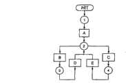
图4简示出在数据处理装置中的数据处理过程。Fig. 4 schematically shows the data processing procedure in the data processing device.
具体实施方式Detailed ways
所示的按照本发明的行驶控制器实施例包括第一霍耳传感器1和第二霍耳传感器2,它们设置在一个圆弧上,以侧向角间距扁平状地固定在印制电路板4的一侧上。在印制电路板4上方,在一个磁轭5上安置两个永磁体3、6。永磁体3和6这样定位,即,使其极轴平行地、但是在相反的方向上延伸。该磁轭5一方面作为磁性载体,另一方面用于将磁通量线集束地从一个永磁体传导到另一永磁体。The illustrated embodiment of the drive controller according to the invention comprises a
该磁轭5呈部分环形地构造并且可以由其在图1和2中所示的中间位置以约±30°围绕轴S偏移。The
在印制电路板4的与霍耳传感器1、2对置的一侧上同样设置一个磁轭7,它同样呈部分环形地构造并且在约180°的角度范围上这样延伸,使得磁轭5在±30°的角偏转中总被磁轭7覆盖,由此使磁场线总是穿过磁轭7集束,而形成一个封闭的、稳定的磁场,其场线穿过霍耳传感器。该封闭的磁场在图2中通过以8表示的椭圆表示。Also arranged on the side of the printed
在图3中示出了在霍耳传感器1,2中由于磁场8而产生的霍耳电压与磁轭5从图1和2所示的以0°表示的中立位置的角偏转的关系。如图所示,霍耳传感器1的霍耳电压在0至+30°的范围内显示出3至2V之间的大致线性的走向。曲线的这个范围以实线示出。相应地,霍耳传感器2的霍耳电压在0至-30°的范围内显示出在2至3V之间的与角度的线性关系。这个范围同样以实线表示。基于这种几乎线性的关系,在附图中未示出的数据处理装置使用霍耳电压依据给定的理论速度模拟地控制地面输送车辆的马达。模拟的电压输出信号最好通过A/D转换器进行转换、处理然后以数字形式例如串联地通过CAN总线等等传递到马达控制装置。当时另外的那个霍耳传感器的霍耳电压值在几乎线性的范围中差不多位于一个水平上,如同在图3中虚线所示的那样,该霍耳电压值被数据处理装置用于合理性检验,如果霍耳电压不对应于期待的理论值而超过一定的误差范围,则使地面输送车辆的马达停机。为此,由数据处理装置来检验:当时另外的那个霍耳传感器的霍耳电压值是否位于确定的阈值以上或以下,并据此产生信号0或1。当所述另外的那个霍耳传感器的霍耳电压值处于阈值的所期待的一侧时,地面输送车辆的马达才用一个行驶信号进行控制。FIG. 3 shows the Hall voltage generated in the
霍耳传感器1、2与数据处理装置连接,该数据处理装置的一种优选设计产生下面的输出信号:The
-马达控制:来自相应霍耳传感器的模拟信号,没有方向信息;- Motor control: analog signal from corresponding Hall sensor, without direction information;
-中立:数字信号,当检测到表征磁性载体中立位置的霍耳传感器1和2霍耳电压特性时,产生该信号;- Neutral: a digital signal, which is generated when the
-向前:关于目标方向的数字信号,借助所检测到的霍耳传感器1和2的霍耳电压特性产生;- Forward: a digital signal about the direction of the target, generated with the help of the detected Hall voltage characteristics of
-向后:以相应方式产生的数字信号。- Backwards: digital signals generated in a corresponding manner.
数据处理装置使用下面的值:The data handler uses the following values:
-V1:在磁性载体按正的旋转方向完全偏转时(在这里为+30°)霍耳传感器1的霍耳电压;-V1: Hall voltage of the
-V2:在磁性载体按负的旋转方向最大偏转时(在这里为-30°)霍耳传感器1的霍耳电压;-V2: Hall voltage of the
-V3:按正的旋转方向在中立位置边缘处霍耳传感器1的霍耳电压;-V3: Hall voltage of
-V4:按负的旋转方向在中立位置边缘处霍耳传感器1的霍耳电压;-V4: Hall voltage of the
-V11:在磁性载体按正的旋转方向完全偏转时(在这里为+30°)霍耳传感器2霍耳电压;-V11:
-V12:在磁性载体按负的旋转方向最大偏转时(在这里为-30°)霍耳传感器2的霍耳电压;-V12: Hall voltage of the
-V13:按正的旋转方向在中立位置边缘处霍耳传感器2的霍耳电压;-V13: Hall voltage of the
-V14:按负的旋转方向在中立位置边缘处霍耳传感器2的霍耳电压。-V14: Hall voltage of the
此外,数据处理装置是这样设计的:在中立位置,输出信号为非激活的,即马达控制=0,中立信号=1,向前信号=0,向后信号=0。只有当磁性载体从中立位置偏移并且没有检测到故障状态的时候,数据处理装置才转换到激活模式。Furthermore, the data processing device is designed such that in the neutral position the output signal is inactive, ie motor control=0, neutral signal=1, forward signal=0, reverse signal=0. The data processing device switches to active mode only when the magnetic carrier is deflected from the neutral position and no fault condition is detected.
在图4中示出了通过数据处理装置处理数据的流程。在第一步骤A中检验:霍耳传感器1的霍耳电压是否位于V4至V3的范围内,以及霍耳电压2的值是否位于V14至V13的范围内。如果不是这种情况,则检验:霍耳传感器1的霍耳电压是否大于V3,以及霍耳传感器2的霍耳电压是否大于V13。此外检验:霍耳传感器1的霍耳电压是否小于V4,以及霍耳传感器2的霍耳电压是否大于V14。如果能够确定上述的状态之一,则数据处理装置的输出处于非激活状态,即,不控制地面输送车辆的马达。只有当没有检测到上述霍耳电压特性(它们或者意味着磁性载体的中立位置或者意味着故障状态)时,对于霍耳传感器1的电压小于V3或者霍耳传感器2的霍耳电压大于V14的情况,借助于相应的模拟的霍耳电压由下式计算控制信号,而且是用于向前方向:The flow of data processing by the data processing device is shown in FIG. 4 . In a first step A it is checked whether the Hall voltage of
(霍耳传感器1的霍耳电压-V3)/(V01-V03)*Vmax,其中,Vmax是对应于最大速度的霍耳电压值。(Hall voltage of Hall sensor 1-V3)/(V01-V03)*Vmax, where Vmax is the value of the Hall voltage corresponding to the maximum speed.
相应地,按照下式计算用于向后方向的控制信号:Accordingly, the control signal for the backward direction is calculated as follows:
(V14-霍耳传感器2的霍耳电压)/(V14-V12)*Vmax(V14-Hall voltage of Hall sensor 2)/(V14-V12)*Vmax
在已经求得实际的控制值以后,将它与值Vmax进行比较,并且,若实际值更大,则限制到Vmax。After the actual control value has been ascertained, it is compared with the value Vmax and, if the actual value is greater, limited to Vmax.
试验已经证实,在所述的实施例中,下面的电压值是特别适合的:Tests have shown that, in the examples described, the following voltage values are particularly suitable:
V03=2.336VV03 = 2.336V
V04=1.755VV04 = 1.755V
V13=3.33VV13 = 3.33V
V14=2.786VV14 = 2.786V
当然,在按本发明的行驶控制器的其它实施例中可能需要其它的电压值。Of course, other voltage values may be required in other embodiments of the drive controller according to the invention.
作为用于其它参数的标准值,已经证实适合的是:As standard values for the other parameters, it has been found to be suitable:
V01=4.140VV01 = 4.140V
V02=0.327VV02 = 0.327V
V11=4.526VV11 = 4.526V
V12=1.300VV12 = 1.300V
但这些值可以变化并且被存储在数据处理装置中,具体而言是按下面的三个步骤:However, these values can be varied and stored in the data processing device, specifically in the following three steps:
1.磁性载体在正的方向上最大偏转,并且存储测得的霍耳传感器1的霍耳电压为V01,以及存储测得的霍耳传感器2的霍耳电压为V11;1. The maximum deflection of the magnetic carrier in the positive direction, and store the measured Hall voltage of the
2.磁性载体在负的方向上最大偏转,并且存储测得的霍耳传感器1的霍耳电压为V02,以及存储测得的霍耳传感器2的霍耳电压为V12;2. The maximum deflection of the magnetic carrier in the negative direction, and store the measured Hall voltage of the
3.在数据处理装置的永久存储器中存储这些变化的值。3. Store these changed values in the permanent memory of the data processing device.
Claims (10)
Applications Claiming Priority (3)
| Application Number | Priority Date | Filing Date | Title |
|---|---|---|---|
| DE202005016726.6 | 2005-10-24 | ||
| DE202005016726UDE202005016726U1 (en) | 2005-10-24 | 2005-10-24 | Driving switch for controlling a traction drive of a power-driven industrial truck |
| PCT/EP2006/009512WO2007048481A1 (en) | 2005-10-24 | 2006-09-30 | Controller for controlling a drive mechanism of a powered industrial truck |
Publications (2)
| Publication Number | Publication Date |
|---|---|
| CN101297485A CN101297485A (en) | 2008-10-29 |
| CN101297485Btrue CN101297485B (en) | 2012-06-27 |
Family
ID=37776566
Family Applications (1)
| Application Number | Title | Priority Date | Filing Date |
|---|---|---|---|
| CN2006800396303AExpired - Fee RelatedCN101297485B (en) | 2005-10-24 | 2006-09-30 | Travel controllers for controlling the travel gear of powered ground delivery vehicles |
Country Status (9)
| Country | Link |
|---|---|
| US (1) | US7878289B2 (en) |
| EP (2) | EP1941614B1 (en) |
| JP (2) | JP4733188B2 (en) |
| CN (1) | CN101297485B (en) |
| DE (1) | DE202005016726U1 (en) |
| ES (1) | ES2721544T3 (en) |
| SI (1) | SI1941614T1 (en) |
| TR (1) | TR201904240T4 (en) |
| WO (1) | WO2007048481A1 (en) |
Families Citing this family (6)
| Publication number | Priority date | Publication date | Assignee | Title |
|---|---|---|---|---|
| FR2954823A1 (en) | 2009-12-28 | 2011-07-01 | Continental Automotive France | METHOD FOR DETERMINING THE POSITION OF A MAGNETIC ELEMENT USING LINEAR HALL EFFECT SENSORS AND DEVICE THEREFOR |
| JP2013523528A (en) | 2010-04-07 | 2013-06-17 | アルコン リサーチ, リミテッド | System and method for a caster to respond to an obstacle |
| JP5689949B2 (en) | 2010-04-07 | 2015-03-25 | アルコン リサーチ, リミテッド | System and method for console braking |
| US9089367B2 (en) | 2010-04-08 | 2015-07-28 | Alcon Research, Ltd. | Patient eye level touch control |
| DE102016211448A1 (en)* | 2016-06-27 | 2017-12-28 | Schaeffler Technologies AG & Co. KG | Method and device for measuring an angular position for a clutch release system with a sensor with different measuring ranges |
| CN115333519B (en)* | 2022-08-10 | 2023-04-07 | 上海纳恩汽车技术股份有限公司 | Vehicle start switch, vehicle start control system, and vehicle start control method |
Citations (4)
| Publication number | Priority date | Publication date | Assignee | Title |
|---|---|---|---|---|
| US6227320B1 (en)* | 1997-09-03 | 2001-05-08 | Jungheinrich Aktiengesellschaft | Follower industrial truck with handle lever |
| CN1294074A (en)* | 1999-10-22 | 2001-05-09 | 雅马哈发动机株式会社 | Small vehicle with electric boosting function |
| US6276485B1 (en)* | 1998-12-30 | 2001-08-21 | Bt Industries Ab | Device at tiller truck |
| EP1180473A1 (en)* | 2000-08-09 | 2002-02-20 | REMA Lipprandt GmbH & Co. KG | Drawbarhead with a drive switch for an industrial truck guided by a drawbar |
Family Cites Families (24)
| Publication number | Priority date | Publication date | Assignee | Title |
|---|---|---|---|---|
| DE3213151A1 (en)* | 1982-04-08 | 1983-10-20 | Brown, Boveri & Cie Ag, 6800 Mannheim | Four-quadrant position sensor |
| DE3431523A1 (en)* | 1984-08-28 | 1986-03-06 | Oelsch KG, 1000 Berlin | Control-signal transmitter |
| JP2547847B2 (en)* | 1989-06-14 | 1996-10-23 | 日産自動車株式会社 | Automotive power plant structure |
| JPH03226625A (en)* | 1990-02-01 | 1991-10-07 | Fujitsu Ltd | rotary positioner |
| DE4328427C2 (en)* | 1993-08-24 | 2003-08-07 | Teves Gmbh Alfred | Hall switch |
| CH688065A5 (en)* | 1994-02-09 | 1997-04-30 | Genge & Thoma Ag | For two-dimensional or two-dimensional controlling measuring serving arrangement. |
| JP3544226B2 (en)* | 1994-05-30 | 2004-07-21 | ヤマハ発動機株式会社 | Throttle opening detector |
| FR2731393B1 (en)* | 1995-03-06 | 1997-05-30 | Magneti Marelli France | LEVER CONTROL ASSEMBLY, ESPECIALLY FOR ROBOTIC MECHANICAL GEARBOX |
| DE19756475A1 (en)* | 1996-12-20 | 1998-06-25 | Linde Ag | Operating lever esp joystick for controlling vehicle such as fork-lift truck or production machine |
| DE19749330C2 (en)* | 1997-11-07 | 2003-10-30 | Kostal Leopold Gmbh & Co Kg | Device for detecting switching positions of a mechanically actuated switching means |
| DE20004887U1 (en)* | 2000-03-17 | 2000-06-29 | Elektron-Bremen Fabrik für Elektrotechnik GmbH, 28197 Bremen | Proportional button with Hall sensor |
| JP3640602B2 (en)* | 2000-08-17 | 2005-04-20 | 日本輸送機株式会社 | Lift truck |
| US6753680B2 (en)* | 2000-11-29 | 2004-06-22 | Ronald J. Wolf | Position sensor |
| JP2002243407A (en)* | 2001-02-14 | 2002-08-28 | Yaskawa Electric Corp | Rotation angle detector and its device |
| JP4235105B2 (en)* | 2001-08-07 | 2009-03-11 | 並木精密宝石株式会社 | Magnetic microencoder and micromotor |
| JP3839697B2 (en)* | 2001-10-17 | 2006-11-01 | アルプス電気株式会社 | Rotation angle sensor |
| US7221151B2 (en)* | 2003-01-31 | 2007-05-22 | Delphi Technologies, Inc. | Magnetic array position sensor |
| US6960973B2 (en)* | 2003-06-18 | 2005-11-01 | The Cherry Corporation | Angular position sensor |
| DE10334869B3 (en)* | 2003-07-29 | 2004-09-16 | Tech3 E.K. | Rotation angle sensor has a rotating shaft with attached permanent magnets, with angular measurements based on both axial displacement of the shaft and sinusoidal and cosinusoidal signals generated by it |
| US7023202B2 (en)* | 2003-08-01 | 2006-04-04 | Japan Servo Co., Ltd. | Magnetic rotary position sensor |
| US6940275B2 (en)* | 2003-12-15 | 2005-09-06 | Texas Instruments Incorporated | Magnetic position sensor apparatus and method |
| JP2005223221A (en)* | 2004-02-06 | 2005-08-18 | Denso Corp | Magnetic detector and its manufacturing method |
| US6816770B1 (en)* | 2004-03-26 | 2004-11-09 | Sunpex Technology Co., Ltd. | Direction and speed control device for a motor vehicle |
| JP2005345153A (en)* | 2004-05-31 | 2005-12-15 | Denso Corp | Rotation angle detector |
- 2005
- 2005-10-24DEDE202005016726Upatent/DE202005016726U1/ennot_activeExpired - Lifetime
- 2006
- 2006-09-30WOPCT/EP2006/009512patent/WO2007048481A1/enactiveApplication Filing
- 2006-09-30USUS12/090,996patent/US7878289B2/enactiveActive
- 2006-09-30EPEP06792337.5Apatent/EP1941614B1/enactiveActive
- 2006-09-30ESES06792337Tpatent/ES2721544T3/enactiveActive
- 2006-09-30CNCN2006800396303Apatent/CN101297485B/ennot_activeExpired - Fee Related
- 2006-09-30JPJP2008535921Apatent/JP4733188B2/ennot_activeExpired - Fee Related
- 2006-09-30SISI200632327Tpatent/SI1941614T1/enunknown
- 2006-09-30EPEP13177157.8Apatent/EP2658128B1/ennot_activeNot-in-force
- 2006-09-30TRTR2019/04240Tpatent/TR201904240T4/enunknown
- 2011
- 2011-02-22JPJP2011036089Apatent/JP5101712B2/ennot_activeExpired - Fee Related
Patent Citations (4)
| Publication number | Priority date | Publication date | Assignee | Title |
|---|---|---|---|---|
| US6227320B1 (en)* | 1997-09-03 | 2001-05-08 | Jungheinrich Aktiengesellschaft | Follower industrial truck with handle lever |
| US6276485B1 (en)* | 1998-12-30 | 2001-08-21 | Bt Industries Ab | Device at tiller truck |
| CN1294074A (en)* | 1999-10-22 | 2001-05-09 | 雅马哈发动机株式会社 | Small vehicle with electric boosting function |
| EP1180473A1 (en)* | 2000-08-09 | 2002-02-20 | REMA Lipprandt GmbH & Co. KG | Drawbarhead with a drive switch for an industrial truck guided by a drawbar |
Also Published As
| Publication number | Publication date |
|---|---|
| TR201904240T4 (en) | 2019-04-22 |
| US7878289B2 (en) | 2011-02-01 |
| DE202005016726U1 (en) | 2007-03-01 |
| EP1941614A1 (en) | 2008-07-09 |
| JP4733188B2 (en) | 2011-07-27 |
| SI1941614T1 (en) | 2019-06-28 |
| EP1941614B1 (en) | 2019-02-20 |
| ES2721544T3 (en) | 2019-08-01 |
| US20080223650A1 (en) | 2008-09-18 |
| WO2007048481A1 (en) | 2007-05-03 |
| EP2658128B1 (en) | 2014-11-05 |
| EP2658128A1 (en) | 2013-10-30 |
| CN101297485A (en) | 2008-10-29 |
| JP5101712B2 (en) | 2012-12-19 |
| JP2009512971A (en) | 2009-03-26 |
| JP2011100752A (en) | 2011-05-19 |
Similar Documents
| Publication | Publication Date | Title |
|---|---|---|
| CN101297485B (en) | Travel controllers for controlling the travel gear of powered ground delivery vehicles | |
| EP2715385B1 (en) | Detecting device and current sensor | |
| KR102010608B1 (en) | Operating device | |
| CN110573408B (en) | Torque sensor assembly for a vehicle power steering system | |
| JP5166068B2 (en) | Position detecting device and shift lever device | |
| CN101430187A (en) | Movable body position detecting device | |
| JP2011080839A (en) | Position detecting device and shift device | |
| CN107000782A (en) | Transfer and the method for controlling transfer | |
| US8353393B2 (en) | Operator interface controllable brake with field responsive material | |
| JP2011143852A (en) | Shift position detection device | |
| JP4215310B2 (en) | Vehicle rudder angle detection device | |
| US20080234908A1 (en) | Operator input device for controlling a vehicle operation | |
| KR20160016757A (en) | Motion plaform configuration | |
| US9751475B2 (en) | Linear sensor apparatus for vehicle | |
| US9770668B2 (en) | Angle detecting device and servo apparatus using same | |
| JP4955595B2 (en) | Position detection device | |
| CN106796253B (en) | Current detection means and electric current detecting method | |
| KR20200107671A (en) | Pedal stroke sensing device | |
| US7210453B2 (en) | Throttle control method and apparatus | |
| CN117657288B (en) | Displacement detection device, system and method | |
| WO2023171496A1 (en) | Operation stroke detection unit, trigger switch, and electrical power tool | |
| US20190372487A1 (en) | Method and controller for operating an actuator device, and actuator system | |
| CN107284597A (en) | A kind of control method and mobile device | |
| JP2008296882A (en) | Control position detection device and shift device |
Legal Events
| Date | Code | Title | Description |
|---|---|---|---|
| C06 | Publication | ||
| PB01 | Publication | ||
| C10 | Entry into substantive examination | ||
| SE01 | Entry into force of request for substantive examination | ||
| C14 | Grant of patent or utility model | ||
| GR01 | Patent grant | ||
| CF01 | Termination of patent right due to non-payment of annual fee | ||
| CF01 | Termination of patent right due to non-payment of annual fee | Granted publication date:20120627 |