CN101296137B - A method for realizing controllable timing work of data terminal unit - Google Patents
A method for realizing controllable timing work of data terminal unitDownload PDFInfo
- Publication number
- CN101296137B CN101296137BCN200710076730XACN200710076730ACN101296137BCN 101296137 BCN101296137 BCN 101296137BCN 200710076730X ACN200710076730X ACN 200710076730XACN 200710076730 ACN200710076730 ACN 200710076730ACN 101296137 BCN101296137 BCN 101296137B
- Authority
- CN
- China
- Prior art keywords
- timing
- terminal unit
- data
- data terminal
- time
- Prior art date
- Legal status (The legal status is an assumption and is not a legal conclusion. Google has not performed a legal analysis and makes no representation as to the accuracy of the status listed.)
- Active
Links
- 238000000034methodMethods0.000titleclaimsabstractdescription20
- 238000012545processingMethods0.000claimsabstractdescription45
- 238000013480data collectionMethods0.000claimsabstractdescription12
- 230000005540biological transmissionEffects0.000claimsdescription44
- 238000005259measurementMethods0.000claimsdescription10
- 238000005265energy consumptionMethods0.000abstract1
- 238000004891communicationMethods0.000description9
- 230000009286beneficial effectEffects0.000description2
- 238000010586diagramMethods0.000description2
- 230000005611electricityEffects0.000description2
- 230000006870functionEffects0.000description2
- 238000012544monitoring processMethods0.000description2
- 230000007812deficiencyEffects0.000description1
- 238000011161developmentMethods0.000description1
- 230000007613environmental effectEffects0.000description1
- 238000010295mobile communicationMethods0.000description1
- 230000001568sexual effectEffects0.000description1
- 238000012546transferMethods0.000description1
- 230000001960triggered effectEffects0.000description1
- XLYOFNOQVPJJNP-UHFFFAOYSA-NwaterSubstancesOXLYOFNOQVPJJNP-UHFFFAOYSA-N0.000description1
Images

Classifications
- Y—GENERAL TAGGING OF NEW TECHNOLOGICAL DEVELOPMENTS; GENERAL TAGGING OF CROSS-SECTIONAL TECHNOLOGIES SPANNING OVER SEVERAL SECTIONS OF THE IPC; TECHNICAL SUBJECTS COVERED BY FORMER USPC CROSS-REFERENCE ART COLLECTIONS [XRACs] AND DIGESTS
- Y02—TECHNOLOGIES OR APPLICATIONS FOR MITIGATION OR ADAPTATION AGAINST CLIMATE CHANGE
- Y02D—CLIMATE CHANGE MITIGATION TECHNOLOGIES IN INFORMATION AND COMMUNICATION TECHNOLOGIES [ICT], I.E. INFORMATION AND COMMUNICATION TECHNOLOGIES AIMING AT THE REDUCTION OF THEIR OWN ENERGY USE
- Y02D30/00—Reducing energy consumption in communication networks
- Y02D30/70—Reducing energy consumption in communication networks in wireless communication networks
Landscapes
- Mobile Radio Communication Systems (AREA)
Abstract
Description
Translated fromChinese技术领域technical field
本发明涉及一种远程无线数据采集系统,特别涉及一种实现数据终端单元可控制定时工作的方法。 The invention relates to a remote wireless data acquisition system, in particular to a method for realizing the controllable timing work of a data terminal unit. the
背景技术Background technique
伴随着GPRS(General Packet Radio Service,通用分组无线业务)的迅猛发展,GPRS DTU(Data Terminal Unit,数据终端单元)已经广泛应用于电力系统自动化、工业监控、交通管理、气象、金融以及证券等部门。GPRS DTU是能够读取用户数据,具有通讯功能,实现用户和数据服务中心间信息交换功能的无线终端设备。 With the rapid development of GPRS (General Packet Radio Service, General Packet Radio Service), GPRS DTU (Data Terminal Unit, Data Terminal Unit) has been widely used in power system automation, industrial monitoring, traffic management, meteorology, finance and securities and other departments . GPRS DTU is a wireless terminal device that can read user data, has communication functions, and realizes information exchange between users and data service centers. the
由于考虑到实时在线的功能,目前市场上的DTU在产品功耗方面都维持相对较高的水平。 Due to the real-time online function, the DTUs currently on the market maintain a relatively high level of product power consumption. the
针对行业应用,为了尽可能的降低功耗,现有的DTU工作模式通常有如下三种: For industrial applications, in order to reduce power consumption as much as possible, the existing DTU working modes usually have the following three types:
1.用户数据触发上线。即当用户需要发送数据时,用户数据通过连接线传输至DTU,DTU收到数据后连接至DSC(data service centre,数据服务中心)数据服务中心,实现数据转发。 1. User data triggers online. That is, when the user needs to send data, the user data is transmitted to the DTU through the connection line, and the DTU connects to the DSC (data service center, data service center) data service center after receiving the data to realize data forwarding. the
2.短信中心呼叫触发上线。即当短信中心发送短信或打电话呼叫DTU时,DTU连接至DSC数据服务中心,实现数据转发。 2. The SMS center call triggers the online. That is, when the SMS center sends a text message or makes a phone call to call the DTU, the DTU is connected to the DSC data service center to realize data forwarding. the
3.一直在线。即DTU上电后就连接到DSC中心,随时可以实现数据转发。 3. Always online. That is, after the DTU is powered on, it is connected to the DSC center, and data forwarding can be realized at any time. the
例如,中国发明专利申请号CN200510050700.2公开了一种名为《基于GPRS网络的电力远程自动抄表系统》的技术方案,该技术方案为由电能表、终端、主站以及终端和主站之间的通讯电路组成,所述的终端以嵌入式处理器为核心,外接程序存储器FLASH和数据存储器SDRAM,外扩GPRS通讯模块和RS485串口通讯模块,模块上设有相应的通讯接口;终端采用嵌入式Linux操作系统;所述的通讯电路由GPRS网络和Internet网络组成,终端通过RS485串口通讯模块下挂多个电能表,并通过GPRS通讯模块接入GPRS网络,主站与Internet网络相连并通过Internet网关实现与GPRS网络通讯。 For example, Chinese Invention Patent Application No. CN200510050700.2 discloses a technical solution called "Power Remote Automatic Meter Reading System Based on GPRS Network". The terminal is composed of an embedded processor as the core, an external program memory FLASH and a data memory SDRAM, an externally expanded GPRS communication module and an RS485 serial communication module, and the module is equipped with a corresponding communication interface; the terminal adopts an embedded Linux operating system; the communication circuit is composed of a GPRS network and an Internet network. The terminal hangs multiple electric energy meters through the RS485 serial port communication module, and accesses the GPRS network through the GPRS communication module. Gateway realizes communication with GPRS network. the
通过对以上专利整个文件的分析可以看出,该技术方案没有对如何节电做出任何考虑。 It can be seen from the analysis of the entire document of the above patent that this technical solution does not take any consideration on how to save electricity. the
再如,中国发明专利号CN200510053888.6公开了一种名为《移动数据终端及其通信方法》的技术方案,该技术方案为节电所采取的措施是如下的CPU时钟控制步骤:如果所述移动数据终端在服务区内或服务区外被置于等待状态中,则将已经在所述移动数据终端的繁忙状态中所设置的CPU操作时钟信号改变到低速度的CPU操作时钟信号。 For another example, Chinese Invention Patent No. CN200510053888.6 discloses a technical solution called "Mobile Data Terminal and Its Communication Method". The measures taken by the technical solution for power saving are the following CPU clock control steps: When the mobile data terminal is placed in a waiting state inside or outside the service area, the CPU operation clock signal that has been set in the busy state of the mobile data terminal is changed to a low-speed CPU operation clock signal. the
通过对以上专利整个文件的分析可以看出,该技术方案只适合用于移动通讯的终端,并不适合其它特殊行业的应用。 Through the analysis of the entire document of the above patent, it can be seen that this technical solution is only suitable for mobile communication terminals, and is not suitable for applications in other special industries. the
这三种工作模式在一定程度上满足了一些行业的需要,但在一些特殊行业应用中,如水表、电表、环境监测等要求设备功耗尽可能的低、数据传输在时间上有一定的规律性的场合,这三种工作模式就不能满足了。 These three working modes meet the needs of some industries to a certain extent, but in some special industry applications, such as water meters, electricity meters, environmental monitoring, etc., the power consumption of equipment is required to be as low as possible, and data transmission has certain rules in time In sexual occasions, these three working modes cannot be satisfied. the
发明内容Contents of the invention
本发明克服了现有技术中的不足,针对现有DTU不能满足上述特殊行业数据采集场合节电应用的问题,提供了一种实现数据终端单元可控制定时工作的方法。 The invention overcomes the deficiencies in the prior art, and provides a method for realizing the controllable timing operation of the data terminal unit in view of the problem that the existing DTU cannot meet the power-saving application in the above-mentioned special industry data collection occasions. the
实施一种实现数据终端单元可控制定时工作的方法,所述数据终端单元包括定时器、电源控制电路、数据采集处理与传输模块、电源和测控终端,本发明通过采用以下技术方案实现,包括: Implement a method for realizing the controllable timing work of the data terminal unit. The data terminal unit includes a timer, a power supply control circuit, a data acquisition processing and transmission module, a power supply and a measurement and control terminal. The present invention is realized by adopting the following technical solutions, including:
数据终端单元间歇工作,定时与数据服务中心交换数据,所述数据终端单元由待机状态转为正常工作状态,是由定时器触发电源控制电路,从而开启数据采集处理与传输模块的电源,使整个数据终端单元系统开始工作。 The data terminal unit works intermittently and exchanges data with the data service center at regular intervals. The data terminal unit changes from the standby state to the normal working state. The timer triggers the power supply control circuit, thereby turning on the power supply of the data collection, processing and transmission module, so that the entire The data terminal unit system starts working. the
所述数据终端单元系统在启动正常工作后,进入下次待机前,从定时器读取出当前时钟参数,然后读取所有定时列表,从列表中查找出距离当前时钟参数最近的定时列表,设置该列表为定时报警值,所述的定时列表会得到更新,所述的定时器会接收到数据采集处理与传输模块修改的定时值,设置为下次启动正常工作模式的时间。 The data terminal unit system reads the current clock parameters from the timer before entering the next standby after starting normal work, then reads all timing lists, finds the timing list closest to the current clock parameters from the list, and sets The list is a timing alarm value, the timing list will be updated, the timer will receive the timing value modified by the data acquisition processing and transmission module, and set it as the time to start the normal working mode next time. the
数据终端单元采集测控终端的数据,按照协议进行封包处理并通过无线方式转发给数据服务中心,及数据终端单元通过无线方式接收数据服务中心的命令,按照协议进行解包并转发给测控终端。 The data terminal unit collects the data of the measurement and control terminal, performs packet processing according to the protocol and forwards it to the data service center through wireless means, and the data terminal unit receives the command of the data service center through wireless means, unpacks it according to the protocol and forwards it to the measurement and control terminal. the
然后,数据采集处理与传输模块向电源控制电路发出一个数据终端单元系统待机请求,触发电源控制电路关断数据采集处理与传输模块与电源的连接。 Then, the data acquisition processing and transmission module sends a data terminal unit system standby request to the power control circuit, triggering the power control circuit to shut down the connection between the data acquisition processing and transmission module and the power supply. the
所述数据终端单元进入工作状态后,在进入下次待机前,做如下的操作: After the data terminal unit enters the working state, before entering the next standby, do the following operations:
首先从定时器读取出当前时钟参数, First read the current clock parameters from the timer,
然后读取所有定时列表, Then read all timing lists,
从列表中查找出距离当前时钟参数最近的定时列表,设置该列表为定时报警值,使定时器在运行至此时间时,能够触发电源控制电路,从而接通数据采集处理与传输模块与电源的连接,使整体数据终端单元系统开始工作。 Find the timing list closest to the current clock parameter from the list, set the list as the timing alarm value, so that when the timer runs to this time, it can trigger the power control circuit, thereby connecting the data acquisition processing and transmission module to the power supply , so that the overall data terminal unit system starts working. the
所述数据终端单元在将数据通过无线方式转发给数据服务中心时,为避免遇到大量数据终端单元同时向数据服务中心发送数据造成数据丢失, When the data terminal unit forwards the data to the data service center in a wireless manner, in order to avoid data loss caused by a large number of data terminal units sending data to the data service center at the same time,
各数据终端单元在计算下个定时周期的定时唤醒时间时,会根据本身唯一的编码标识以及配置的有效延时时间来计算出本身发送数据的延迟时间,形成新的定时唤醒时间并修正定时列表。使得数据传输既能避免丢失又能在规定时间内传输到数据服务中心。 When each data terminal unit calculates the timing wake-up time of the next timing cycle, it will calculate the delay time of sending data according to its own unique code identification and the configured effective delay time, form a new timing wake-up time and modify the timing list . The data transmission can not only avoid loss but also be transmitted to the data service center within the specified time. the
当所述的数据终端单元读取所有定时列表,并从中寻找与当前时钟参数最相近的定时列表时,如果最相近的定时列表为二个以上时,则设置其中的一个至定时器,其他的列表按列表定时周期刷新列表。 When the data terminal unit reads all timing lists, and when looking for the timing list closest to the current clock parameter, if the closest timing list is more than two, one of them is set to the timer, and the other The list refreshes the list according to the list timing period. the
设数据终端单元本身唯一编码标识的后8位为flag_value,某一定时列表的有效延时时间为invalid_dtime,则计算出的延迟时间delay_time。 Let the last 8 bits of the unique coded identifier of the data terminal unit itself be flag_value, and the valid delay time of a certain timing list be invalid_dtime, then the calculated delay time delay_time. the
delay_time=flag_value%(invalid_time+1) delay_time=flag_value%(invalid_time+1)
所述的数据终端单元在进入下次待机之前,按周期更新数据采集处理与传输模块中介于当前定时报警值和当前时钟参数值之间的列表,确保没有漏掉任何需要正常工作的定时时间。 Before the data terminal unit enters the next standby mode, it periodically updates the list between the current timing alarm value and the current clock parameter value in the data acquisition processing and transmission module, so as to ensure that no timing time required for normal operation is missed. the
所述数据终端单元设置定时列表,包括数据传输线与计算机连接配置,还包括GPRS或SMS配置。 The timing list set by the data terminal unit includes the data transmission line and computer connection configuration, and also includes GPRS or SMS configuration. the
所述定时器以PCF8563器件为主构成,或者采用与PCF8563器件兼容 的其它时钟器件。 The timer is mainly composed of the PCF8563 device, or other clock devices compatible with the PCF8563 device are adopted. the
与现有技术相比较,本发明采用了定时器来触发电源控制电路,从而使整个数据终端单元系统开始工作,它的有益效果是电源控制电路本身消耗能量在na级,定时器本身的功耗极小,在va数量级,而耗电量较大的数据采集处理与传输模块只在很短的时间内工作,从而使整个数据终端单元系统能在较低功耗下工作,可以保证数据终端单元系统在电池供能的情况下,维持很久的工作时间。满足了一些在野外长期采集数据的特殊行业的需求。 Compared with the prior art, the present invention uses a timer to trigger the power control circuit, so that the entire data terminal unit system starts to work. Its beneficial effect is that the power consumption of the power control circuit itself is at na level, and the power consumption of the timer itself It is extremely small, on the order of va, and the data acquisition processing and transmission module with large power consumption only work in a very short time, so that the entire data terminal unit system can work at lower power consumption, which can ensure that the data terminal unit The system maintains a long working time under the condition of battery power supply. It meets the needs of some special industries that collect data in the field for a long time. the
附图说明Description of drawings
图1是本发明示例性实施例的原理方框图; Fig. 1 is a schematic block diagram of an exemplary embodiment of the present invention;
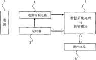
图2是本发明示例性带测控终端实施例的原理方框图。 Fig. 2 is a schematic block diagram of an exemplary embodiment of a terminal with measurement and control in the present invention. the
具体实施方式Detailed ways
下面结合附图和具体实施方式,对本发明作进一步的描述: Below in conjunction with accompanying drawing and specific embodiment, the present invention will be further described:
如图1和图2所示,一个数据终端单元包括数据采集处理与传输模块1、定时器3、电源控制电路4、电源5、测控终端6,一般情况下电源5是电池。 As shown in Figures 1 and 2, a data terminal unit includes a data acquisition, processing and transmission module 1, a
实施一种实现数据终端单元可控制定时工作的方法,包括:数据采集处理与传输模块1定时得电间歇工作,所述数据采集处理与传输模块1由失电待机状态转为得电工作状态,是由定时器3触发电源控制电路4,从而接通数据采集处理与传输模块1与电源5的连接,使整体数据终端单元系统开始工作。 Implement a method for realizing the controllable timing work of the data terminal unit, including: the data collection processing and transmission module 1 is periodically powered on intermittently, and the data collection processing and transmission module 1 is transferred from the power-off standby state to the power-on working state, The power
数据采集处理与传输模块1采集测控终端6的数据,按照协议进行封包处理并通过无线方式转发给数据服务中心,及数据采集处理与传输模块1通过无线方式接收数据服务中心的命令,按照协议进行解包并转发给测控终端6。 The data acquisition processing and transmission module 1 collects the data of the measurement and
然后,数据采集处理与传输模块1给电源控制电路4一个数据终端单元系统关电待机请求,触发电源控制电路4关断数据采集处理与传输模块1与电源5的连接。 Then, the data collection processing and transmission module 1 sends a data terminal unit system shutdown standby request to the
所述数据采集处理与传输模块1进入工作状态后,首先从定时器3读 取出当前时钟参数。 After described data acquisition processing and transmission module 1 enters working state, at first read out current clock parameter from
然后数据采集处理与传输模块1读取所有定时列表,从中寻找与当前时钟参数最相近的定时列表,同时算出下个定时周期的定时唤醒时间,并把此定时唤醒时间更新传输至定时器3。 Then the data acquisition processing and transmission module 1 reads all the timing lists, finds the timing list closest to the current clock parameters, and calculates the timing wake-up time of the next timing cycle, and updates and transmits the timing wake-up time to the
数据采集处理与传输模块1更新定时列表,使定时器3在运行至此唤醒时间时,能够触发电源控制电路4,从而数据采集处理与传输模块1与电源5的连接,使整体数据终端单元系统开始工作。 The data acquisition processing and transmission module 1 updates the timing list so that the
所述数据采集处理与传输模块1通过无线方式转发给数据服务中心时,为避免遇到多个数据终端单元同时向数据服务中心发送数据造成数据丢失,各数据终端单元在计算下个定时周期的定时唤醒时间时,会根据本身唯一的编码标识和配置的有效延时时间间隔计算出本身发送数据的延迟时间,形成新的定时唤醒时间并修正定时列表,使得数据传输既能避免丢失又能在规定时间内传输到数据服务中心。 When the data collection processing and transmission module 1 is forwarded to the data service center by wireless, in order to avoid data loss caused by multiple data terminal units sending data to the data service center at the same time, each data terminal unit calculates the time period of the next timing cycle. When timing wake-up time, it will calculate the delay time of sending data according to its unique coded identifier and configured effective delay time interval, form a new timing wake-up time and modify the timing list, so that data transmission can avoid loss and can be Transfer to the data service center within the specified time. the
当所述的数据采集处理与传输模块1读取所有定时列表,并从中寻找与当前时钟参数最相近的定时列表时,如果最相近的定时列表为二个以上时,则设置其中的一个至定时器3,其他的列表按列表定时周期刷新列表. When described data acquisition processing and transmission module 1 read all timing lists, and when looking for the timing list closest to the current clock parameter, if the closest timing list is more than two, then set one of them to the timing list.
数据采集处理与传输模块1最多可同时保存设置5个定时列表,每个定时列表的周期最小可以是1分钟,也可以是小时,也可以是天,也可以是星期,最大可以是一个月。 The data acquisition processing and transmission module 1 can save and set up to 5 timing lists at the same time, and the minimum period of each timing list can be 1 minute, or hour, or day, or week, and the maximum can be one month. the
设本身唯一编码标识的后8位为flag_value,某一定时列表的有效延时时间为invalid_dtime,则计算出的延迟时间delay_time。 Let flag_value be the last 8 bits of its own unique code identifier, and the valid delay time of a certain timing list be invalid_dtime, then the calculated delay time delay_time. the
delay_time=flag_value%(invalid_dtime+1) delay_time=flag_value%(invalid_dtime+1)
所述的数据采集处理与传输模块1在进入下次待机之前,按周期更新数据采集处理与传输模块1中介于当前定时报警值和当前时钟参数值之间的列表,确保没有漏掉任何需要正常工作的定时时间。 Before entering the next standby mode, the data acquisition processing and transmission module 1 periodically updates the list between the current timing alarm value and the current clock parameter value in the data acquisition processing and transmission module 1 to ensure that any required normal Timing of work. the
所述数据采集处理与传输模块1设置定时列表,包括数据传输线与计算机连接配置,还包括GPRS或SMS配置。 The data acquisition processing and transmission module 1 sets a timing list, including data transmission line and computer connection configuration, and also includes GPRS or SMS configuration. the
所述定时器3以PCF8563器件为主构成,或者采用与PCF8563器件兼容的其它时钟器件。 The
定时器3与数据采集处理与传输模块1的连接通过I2C总线,与电源 控制电路4的连接通过引脚直连。 The connection between the
电源控制电路4由低功耗微处理器和MOSFET管组成,实现数据采集处理与传输模块1的电源控制,数据采集处理与传输模块1为高性能嵌入式32位微处理器。 The
本发明采用了定时器来触发电源控制电路,从而使整个数据终端单元系统开始工作,它的有益效果是电源控制电路本身是消耗能量在na级别,定时器本身的功耗极小,在微安数量级,而耗电量较大的数据采集处理与传输模块只在很短的时间内工作,从而使整个数据终端单元系统能在较低功耗下工作,可以保证数据终端单元系统在电池供能的情况下,维持很久的工作时间。满足了一些在野外长期采集数据的特殊行业的需求。 The present invention uses a timer to trigger the power supply control circuit, so that the entire data terminal unit system starts to work. Its beneficial effect is that the power supply control circuit itself consumes energy at na level, and the power consumption of the timer itself is very small, in the microampere order of magnitude, and the data acquisition processing and transmission module that consumes a lot of power only work in a short time, so that the entire data terminal unit system can work at a lower power consumption, which can ensure that the data terminal unit system is powered by the battery Under the circumstances, maintain a long working time. It meets the needs of some special industries that collect data in the field for a long time. the
以上内容是结合具体的优选实施方式对本发明所作的进一步详细说明,不能认定本发明的具体实施只局限于这些说明。对于本发明所属技术领域的普通技术人员来说,在不脱离本发明构思的前提下,还可以做出若干简单推演或替换,都应当视为属于本发明的保护范围。 The above content is a further detailed description of the present invention in conjunction with specific preferred embodiments, and it cannot be assumed that the specific implementation of the present invention is limited to these descriptions. For those of ordinary skill in the technical field of the present invention, without departing from the concept of the present invention, some simple deduction or replacement can be made, which should be regarded as belonging to the protection scope of the present invention. the
Claims (8)
Translated fromChinesePriority Applications (1)
| Application Number | Priority Date | Filing Date | Title |
|---|---|---|---|
| CN200710076730XACN101296137B (en) | 2007-08-28 | 2007-08-28 | A method for realizing controllable timing work of data terminal unit |
Applications Claiming Priority (1)
| Application Number | Priority Date | Filing Date | Title |
|---|---|---|---|
| CN200710076730XACN101296137B (en) | 2007-08-28 | 2007-08-28 | A method for realizing controllable timing work of data terminal unit |
Publications (2)
| Publication Number | Publication Date |
|---|---|
| CN101296137A CN101296137A (en) | 2008-10-29 |
| CN101296137Btrue CN101296137B (en) | 2011-05-25 |
Family
ID=40066164
Family Applications (1)
| Application Number | Title | Priority Date | Filing Date |
|---|---|---|---|
| CN200710076730XAActiveCN101296137B (en) | 2007-08-28 | 2007-08-28 | A method for realizing controllable timing work of data terminal unit |
Country Status (1)
| Country | Link |
|---|---|
| CN (1) | CN101296137B (en) |
Families Citing this family (7)
| Publication number | Priority date | Publication date | Assignee | Title |
|---|---|---|---|---|
| CN201345645Y (en)* | 2009-02-13 | 2009-11-11 | 深圳华为通信技术有限公司 | Main-control device and wireless terminal |
| CN101958813B (en)* | 2010-09-14 | 2014-06-04 | 中兴通讯股份有限公司 | Method for delaying data acquisition and device thereof |
| CN104361730B (en)* | 2014-10-29 | 2017-09-12 | 梁永富 | The data communication system and transfer approach of intelligent metering instrument |
| CN104486797B (en)* | 2014-12-10 | 2015-11-18 | 骐俊通联(厦门)科技有限公司 | A kind of GPRS terminal based on Serving cell realizes the method and system of Network Load Balance |
| CN106169225A (en)* | 2016-08-27 | 2016-11-30 | 浙江恋尚家居品有限公司 | A kind of large-scale common equipment central station of floating dock unmanned alarm device |
| CN108762468B (en)* | 2018-05-17 | 2021-01-29 | 深圳友讯达科技股份有限公司 | Low-power consumption control method and device |
| CN109870746A (en)* | 2019-03-19 | 2019-06-11 | 南京信息工程大学 | A meteorological data collection system based on Beidou technology |
Citations (7)
| Publication number | Priority date | Publication date | Assignee | Title |
|---|---|---|---|---|
| US5150954A (en)* | 1984-12-05 | 1992-09-29 | Seiko Corporation | Pager watch system utilizing time slot communication |
| US5168271A (en)* | 1985-11-27 | 1992-12-01 | Seiko Corp. | Paging and time keeping system with transmission of time slot identification used for synchronization |
| CN1194564A (en)* | 1996-12-27 | 1998-09-30 | 索尼公司 | Terminal unit for portable telephone system and receiving method |
| JPH11122586A (en) | 1997-10-14 | 1999-04-30 | Victor Co Of Japan Ltd | Data broadcast receiver |
| JPH11284972A (en) | 1998-03-27 | 1999-10-15 | Matsushita Electric Ind Co Ltd | Broadcast transmitting device and broadcast receiving device |
| CN1401159A (en)* | 2000-02-15 | 2003-03-05 | 高通股份有限公司 | Wireles telephone airplane and alarm clock modes |
| CN1499527A (en)* | 2002-10-31 | 2004-05-26 | 海力士半导体有限公司 | Semiconductor memory having self updating for reducing power consumption |
- 2007
- 2007-08-28CNCN200710076730XApatent/CN101296137B/enactiveActive
Patent Citations (7)
| Publication number | Priority date | Publication date | Assignee | Title |
|---|---|---|---|---|
| US5150954A (en)* | 1984-12-05 | 1992-09-29 | Seiko Corporation | Pager watch system utilizing time slot communication |
| US5168271A (en)* | 1985-11-27 | 1992-12-01 | Seiko Corp. | Paging and time keeping system with transmission of time slot identification used for synchronization |
| CN1194564A (en)* | 1996-12-27 | 1998-09-30 | 索尼公司 | Terminal unit for portable telephone system and receiving method |
| JPH11122586A (en) | 1997-10-14 | 1999-04-30 | Victor Co Of Japan Ltd | Data broadcast receiver |
| JPH11284972A (en) | 1998-03-27 | 1999-10-15 | Matsushita Electric Ind Co Ltd | Broadcast transmitting device and broadcast receiving device |
| CN1401159A (en)* | 2000-02-15 | 2003-03-05 | 高通股份有限公司 | Wireles telephone airplane and alarm clock modes |
| CN1499527A (en)* | 2002-10-31 | 2004-05-26 | 海力士半导体有限公司 | Semiconductor memory having self updating for reducing power consumption |
Also Published As
| Publication number | Publication date |
|---|---|
| CN101296137A (en) | 2008-10-29 |
Similar Documents
| Publication | Publication Date | Title |
|---|---|---|
| CN101296137B (en) | A method for realizing controllable timing work of data terminal unit | |
| CN201252572Y (en) | Device for reducing sensor node dormancy power consumption | |
| CN107590987A (en) | A kind of long-distance meter-reading system based on low-power consumption Internet of Things | |
| CN102547944B (en) | Realize the thing net gateway without long-term work under electrical environment and implementation method | |
| CN202587236U (en) | Power transmission line state monitoring low-power communication device based on dormancy awakening mechanism | |
| CN111294906A (en) | Terminal, communication system and communication method | |
| CN207441006U (en) | A kind of long-distance meter-reading system based on low-power consumption Internet of Things | |
| CN103002494A (en) | Device and method for energy-saving control of household long term evolution (LET) router | |
| CN102542218B (en) | Method and system for transmitting radio frequency identification (RFID) data, and hardware platform for RFID label | |
| CN102393257A (en) | Wireless temperature sensor and power equipment temperature on-line monitoring system | |
| CN106648021B (en) | Data broadcasting method of low power consumption circuit and low power consumption circuit | |
| CN110337139B (en) | Low-power-consumption control method based on wireless sensor and wireless sensor | |
| CN105487638A (en) | Electronic circuit system and power consumption reducing method thereof | |
| CN105119726B (en) | A kind of wireless sensing net node fast wake-up method and device thereof | |
| CN111245954A (en) | Data acquisition device for safety monitoring | |
| CN103634885B (en) | A kind of identification card and operation method thereof | |
| CN110572869A (en) | equipment awakening method and device based on BLE and Hall switch | |
| CN103402246A (en) | Method for reducing energy consumption of mobile communications terminal | |
| CN101997963B (en) | Power management method and system for portable communication device | |
| CN204440629U (en) | A kind of low-power consumption bus data acquisition device | |
| CN207965030U (en) | A kind of low-power consumption fault-indicating system | |
| CN114915935A (en) | A Lora-based low-power pig body temperature acquisition and monitoring system | |
| CN210835063U (en) | Intelligent electric energy meter based on LoRaWAN communication | |
| CN204330012U (en) | Based on the building environment state monitoring apparatus of technology of Internet of things | |
| CN208461844U (en) | A kind of smart city monitoring system based on LoRa wireless network |
Legal Events
| Date | Code | Title | Description |
|---|---|---|---|
| C06 | Publication | ||
| PB01 | Publication | ||
| C10 | Entry into substantive examination | ||
| SE01 | Entry into force of request for substantive examination | ||
| C14 | Grant of patent or utility model | ||
| GR01 | Patent grant | ||
| PE01 | Entry into force of the registration of the contract for pledge of patent right | ||
| PE01 | Entry into force of the registration of the contract for pledge of patent right | Denomination of invention:A method for implementing controllable timed operation of data terminal units Granted publication date:20110525 Pledgee:Societe Generale Bank Limited by Share Ltd. Shenzhen branch Pledgor:SHENZHEN HONGDIAN TECHNOLOGIES Corp. Registration number:Y2024980060412 |