CN101295595B - Key - Google Patents
KeyDownload PDFInfo
- Publication number
- CN101295595B CN101295595BCN200710200514ACN200710200514ACN101295595BCN 101295595 BCN101295595 BCN 101295595BCN 200710200514 ACN200710200514 ACN 200710200514ACN 200710200514 ACN200710200514 ACN 200710200514ACN 101295595 BCN101295595 BCN 101295595B
- Authority
- CN
- China
- Prior art keywords
- button
- pressing body
- locking groove
- sealed groove
- connecting portion
- Prior art date
- Legal status (The legal status is an assumption and is not a legal conclusion. Google has not performed a legal analysis and makes no representation as to the accuracy of the status listed.)
- Expired - Fee Related
Links
Images

Classifications
- H—ELECTRICITY
- H01—ELECTRIC ELEMENTS
- H01H—ELECTRIC SWITCHES; RELAYS; SELECTORS; EMERGENCY PROTECTIVE DEVICES
- H01H13/00—Switches having rectilinearly-movable operating part or parts adapted for pushing or pulling in one direction only, e.g. push-button switch
- H01H13/02—Details
- H01H13/12—Movable parts; Contacts mounted thereon
- H01H13/14—Operating parts, e.g. push-button
- H—ELECTRICITY
- H01—ELECTRIC ELEMENTS
- H01H—ELECTRIC SWITCHES; RELAYS; SELECTORS; EMERGENCY PROTECTIVE DEVICES
- H01H2229/00—Manufacturing
- H01H2229/044—Injection moulding
- H01H2229/048—Insertion moulding
- H—ELECTRICITY
- H01—ELECTRIC ELEMENTS
- H01H—ELECTRIC SWITCHES; RELAYS; SELECTORS; EMERGENCY PROTECTIVE DEVICES
- H01H2231/00—Applications
- H01H2231/022—Telephone handset
- H—ELECTRICITY
- H01—ELECTRIC ELEMENTS
- H01H—ELECTRIC SWITCHES; RELAYS; SELECTORS; EMERGENCY PROTECTIVE DEVICES
- H01H2239/00—Miscellaneous
- H01H2239/038—Anti-vandalism
Landscapes
- Push-Button Switches (AREA)
Abstract
Translated fromChinese
Description
Translated fromChinese技术领域technical field
本发明涉及一种按键,特别是一种电子产品用的按键。The invention relates to a key, in particular to a key for electronic products.
背景技术Background technique
随着电子产品的快速发展,便携式电子产品(如移动电话、MP3播放器、MP4播放器、个人数位助理、笔记本电脑等)的使用已非常普遍。而一般作为便携式电子产品控制件的按键则是便携式电子产品不可或缺的构件。With the rapid development of electronic products, the use of portable electronic products (such as mobile phones, MP3 players, MP4 players, personal digital assistants, notebook computers, etc.) has become very common. The buttons generally used as the control parts of the portable electronic products are an indispensable component of the portable electronic products.
按键通常是由塑料材料制成,这主要有如下两点原因:其一是塑料一般具有较低的熔点,较好的流动性,而易于加工出各种结构;其二是在制成的产品中易于在该产品表面形成各种颜色层,满足产品外观的需求。Buttons are usually made of plastic materials. There are two main reasons for this: one is that plastics generally have a lower melting point and better fluidity, and are easy to process into various structures; It is easy to form various color layers on the surface of the product to meet the needs of product appearance.
但是塑料材料制成的按键的表面硬度不足,容易变形、刮伤与磨损,因此会影响便携式电子产品的外观。为解决按键容易变形、刮伤与磨损的问题,现有技术有采用金属材料代替塑料材料来制备按键,以增强按键的表面硬度。However, the surface hardness of the buttons made of plastic materials is insufficient, and they are easily deformed, scratched and worn, thus affecting the appearance of portable electronic products. In order to solve the problem that the keys are easily deformed, scratched and worn, in the prior art, metal materials are used instead of plastic materials to prepare the keys to enhance the surface hardness of the keys.
然而,尽管金属材料通常具有比塑料材料更高的表面硬度,但是按键作为便携式电子产品中最经常被触摸的构件,在一段时间使用后,按键的表面仍容易被刮伤、磨损,且金属材料长期使用后易被氧化、褪色等,因此金属材料按键仍会影响便携式电子产品的外观。However, although metal materials generally have higher surface hardness than plastic materials, keys are the most frequently touched components in portable electronic products. After a period of use, the surface of keys is still easily scratched and worn, and metal materials After long-term use, it is easy to be oxidized, faded, etc., so metal buttons will still affect the appearance of portable electronic products.
发明内容Contents of the invention
鉴于上述内容,有必要提供一种耐刮伤、耐磨损的按键。In view of the above, it is necessary to provide a scratch-resistant and wear-resistant key.
一种按键,其包括按压本体,按压本体包括上表面、与上表面相对的底面及处于该上表面与底面之间的侧面。该按压本体的材质为陶瓷材料,且该按键在该按压本体上还一体成型有一个连接部,该按压本体包括一个锁合槽,该锁合槽开设于该侧面,该锁合槽为V形,该V形锁合槽具有两个相互连接的壁面,其中一个壁面与该底面相连,另一个壁面与该侧面垂直相连,该锁合槽的两个壁面所形成的夹角为50度至70度,该连接部通过射出成型至少部分嵌设于该锁合槽。A key, which includes a pressing body, the pressing body includes an upper surface, a bottom surface opposite to the upper surface, and a side surface between the upper surface and the bottom surface. The pressing body is made of ceramic material, and the button is also integrally formed with a connecting portion on the pressing body. The pressing body includes a locking groove, which is opened on the side, and the locking groove is V-shaped. , the V-shaped locking groove has two interconnected wall surfaces, one of which is connected to the bottom surface, and the other wall surface is vertically connected to the side surface, and the angle formed by the two wall surfaces of the locking groove is 50 degrees to 70 degrees The connecting portion is at least partially embedded in the locking groove through injection molding.
上述按键包括按压本体,按压本体是由陶瓷材料制成,陶瓷材料具有高的表面硬度,因此按键具有强的耐刮伤、耐磨损性能,而可避免按键在使用时被刮伤。The above-mentioned keys include a pressing body, which is made of ceramic material, and the ceramic material has high surface hardness, so the key has strong scratch resistance and wear resistance, and can prevent the key from being scratched during use.
附图说明Description of drawings
图1是本发明较佳实施例一的按键立体分解图。Fig. 1 is a three-dimensional exploded view of a button in a preferred embodiment 1 of the present invention.
图2是图1所示按键的剖面图。FIG. 2 is a cross-sectional view of the button shown in FIG. 1 .
图3是本发明较佳实施例二的按键的剖面图。Fig. 3 is a cross-sectional view of the button according to the second preferred embodiment of the present invention.
具体实施方式Detailed ways
下面将结合附图及实施例对按键做进一步详细说明。The buttons will be described in further detail below in conjunction with the accompanying drawings and embodiments.
请参见图1与图2,所示为本发明较佳实施例一的按键10,其可用于便携式电子装置。按键10包括一个按压本体12与一个位于按压本体12底部一体成型而成的连接部14。按压本体12的材质为陶瓷材料,例如氧化锆(ZrO2)与氧化铝(Al2O3)。为便于加工,按压本体12结构一般可设计得较为简单,具体是根据其所适用的产品确定。连接部14的材质可为塑料材料或金属材料。Please refer to FIG. 1 and FIG. 2 , which show a
本实施例中,按压本体12包括用于与外界相接触的上表面122、与上表面122相对的底面124、与上表面122相连的侧面126及位于底面124与侧面126连接处的锁合槽128。上表面122与底面124为圆形平面,侧面126为圆柱面,锁合槽128的头尾相接形成一个闭合圆环,即其沿侧面126的周向延伸一周。锁合槽128为V形,其具有两个壁面1282、1284,其中一个壁面1282与底面124相连,另一个壁面1284与侧面126垂直相连且与底面124相平行,锁合槽128的两个壁面1282、1284所形成的夹角θ可为50度至70度。连接部14一体成型填充于锁合槽128内。连接部14可为结构较复杂的按键构件,例如作为将按压本体12与便携式电子装置壳体相固定的机构。In this embodiment, the
制备过程中,可先经过干压成型、研磨、表面处理抛光等步骤形成按压本体12;然后将按压本体12嵌入到成型模具中,在按压本体12上射出成型形成连接部14。可以理解,射出成型时连接部14可以部分或全部嵌设于按压本体12的锁合槽128上。During the preparation process, the
由于按键10的按压本体12是由陶瓷材料制成,陶瓷材料一般具有高的表面硬度,因此按键10具有强的耐刮伤、耐磨损性能。且通过改变陶瓷材料的成分,可使陶瓷材料具有不同的表观颜色(如红色、黄色、绿色、蓝色、黑色、灰色、白色及半透明等),加上陶瓷材料具有强的保色性,因此容易使按压本体12的外观得到改善(如呈现珠宝光泽),从而使按键10与便携式电子装置的整体外观相协调,提升便携式电子装置的美感。Since the
此外,上述按键10中,由于连接部14通过射出成型至少部分嵌设于按压本体12的锁合槽128上,使得连接部14可成为一个封闭的环形结构与按压本体12相锁合,因此按压本体12与连接部14之间具有较高的连接强度。且由于连接部14是采用射出成型的方法成型于按压本体12,射出成型的方法易于制备结构复杂的机构,因此还可将结构较为复杂的机构设置于连接部14,而简化按压本体12的结构,从而提升按键10的制备效率。In addition, in the
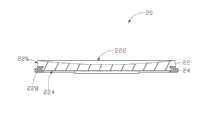
请参见图3,所示为本发明较佳实施例二的按键20。按键20包括按压本体22与连接部24。按压本体22包括上表面222、底面224、侧面226及锁合槽228。其中按压本体22的上表面222为一个圆弧凹面。按压本体22的上表面222为一个圆弧凹面,其可使按压按键20的过程会更为舒适。当然上表面222还可为凸面。Please refer to FIG. 3 , which shows the
可以理解,在上述按键10、20中,当锁合槽128、228的壁面为粗糙面或在锁合槽128、228内开设有另外的凹槽,还可使按压本体12、22与连接部14、24之间的连接强度进一步增强。锁合槽128、228所形成环形还可以不闭合但配以粗糙的壁面,当然,锁合槽128、228也可以只设成不闭合的环形以满足当按压本体12、22与连接部14、24所需的特殊结构而结合力较小时的情况。锁合槽128、228也可直接开设于按压本体12、22的侧面126、226上或底面124、224上,而不仅限于按压本体12、22的侧面126、226与底面124、224的连接处。It can be understood that, in the
此外,可以理解,为配合便携式电子产品整体外观,上述按键的按压本体的还可为俯视图为圆形外的其他形状,例如椭圆形或多边形。按键还可用于便携式电子产品的其他电子产品,如计算机。In addition, it can be understood that, in order to match the overall appearance of the portable electronic product, the pressing body of the above-mentioned key may also be in a shape other than a circle in a top view, such as an ellipse or a polygon. Keys are also used in other electronics in portable electronics, such as computers.
Claims (6)
Priority Applications (2)
| Application Number | Priority Date | Filing Date | Title |
|---|---|---|---|
| CN200710200514ACN101295595B (en) | 2007-04-26 | 2007-04-26 | Key |
| US11/964,732US20080264767A1 (en) | 2007-04-26 | 2007-12-27 | Push buttons |
Applications Claiming Priority (1)
| Application Number | Priority Date | Filing Date | Title |
|---|---|---|---|
| CN200710200514ACN101295595B (en) | 2007-04-26 | 2007-04-26 | Key |
Publications (2)
| Publication Number | Publication Date |
|---|---|
| CN101295595A CN101295595A (en) | 2008-10-29 |
| CN101295595Btrue CN101295595B (en) | 2012-10-10 |
Family
ID=39885675
Family Applications (1)
| Application Number | Title | Priority Date | Filing Date |
|---|---|---|---|
| CN200710200514AExpired - Fee RelatedCN101295595B (en) | 2007-04-26 | 2007-04-26 | Key |
Country Status (2)
| Country | Link |
|---|---|
| US (1) | US20080264767A1 (en) |
| CN (1) | CN101295595B (en) |
Families Citing this family (39)
| Publication number | Priority date | Publication date | Assignee | Title |
|---|---|---|---|---|
| US7312785B2 (en) | 2001-10-22 | 2007-12-25 | Apple Inc. | Method and apparatus for accelerated scrolling |
| US7333092B2 (en) | 2002-02-25 | 2008-02-19 | Apple Computer, Inc. | Touch pad for handheld device |
| US7499040B2 (en) | 2003-08-18 | 2009-03-03 | Apple Inc. | Movable touch pad with added functionality |
| US20070152977A1 (en) | 2005-12-30 | 2007-07-05 | Apple Computer, Inc. | Illuminated touchpad |
| US7495659B2 (en) | 2003-11-25 | 2009-02-24 | Apple Inc. | Touch pad for handheld device |
| US8059099B2 (en) | 2006-06-02 | 2011-11-15 | Apple Inc. | Techniques for interactive input to portable electronic devices |
| WO2006023569A1 (en) | 2004-08-16 | 2006-03-02 | Fingerworks, Inc. | A method of increasing the spatial resolution of touch sensitive devices |
| US7880729B2 (en) | 2005-10-11 | 2011-02-01 | Apple Inc. | Center button isolation ring |
| US20070152983A1 (en) | 2005-12-30 | 2007-07-05 | Apple Computer, Inc. | Touch pad with symbols based on mode |
| US9360967B2 (en) | 2006-07-06 | 2016-06-07 | Apple Inc. | Mutual capacitance touch sensing device |
| US8022935B2 (en) | 2006-07-06 | 2011-09-20 | Apple Inc. | Capacitance sensing electrode with integrated I/O mechanism |
| US8743060B2 (en) | 2006-07-06 | 2014-06-03 | Apple Inc. | Mutual capacitance touch sensing device |
| US7795553B2 (en)* | 2006-09-11 | 2010-09-14 | Apple Inc. | Hybrid button |
| US8274479B2 (en) | 2006-10-11 | 2012-09-25 | Apple Inc. | Gimballed scroll wheel |
| US8482530B2 (en) | 2006-11-13 | 2013-07-09 | Apple Inc. | Method of capacitively sensing finger position |
| US8683378B2 (en) | 2007-09-04 | 2014-03-25 | Apple Inc. | Scrolling techniques for user interfaces |
| WO2009032898A2 (en) | 2007-09-04 | 2009-03-12 | Apple Inc. | Compact input device |
| US8416198B2 (en) | 2007-12-03 | 2013-04-09 | Apple Inc. | Multi-dimensional scroll wheel |
| US8125461B2 (en) | 2008-01-11 | 2012-02-28 | Apple Inc. | Dynamic input graphic display |
| US8820133B2 (en) | 2008-02-01 | 2014-09-02 | Apple Inc. | Co-extruded materials and methods |
| US9454256B2 (en) | 2008-03-14 | 2016-09-27 | Apple Inc. | Sensor configurations of an input device that are switchable based on mode |
| US8816967B2 (en) | 2008-09-25 | 2014-08-26 | Apple Inc. | Capacitive sensor having electrodes arranged on the substrate and the flex circuit |
| USD676439S1 (en)* | 2008-12-03 | 2013-02-19 | Sony Corporation | Computer |
| US8395590B2 (en) | 2008-12-17 | 2013-03-12 | Apple Inc. | Integrated contact switch and touch sensor elements |
| US9354751B2 (en) | 2009-05-15 | 2016-05-31 | Apple Inc. | Input device with optimized capacitive sensing |
| US8872771B2 (en) | 2009-07-07 | 2014-10-28 | Apple Inc. | Touch sensing device having conductive nodes |
| CN102049957A (en)* | 2009-10-29 | 2011-05-11 | 深圳富泰宏精密工业有限公司 | Ceramoplastic composite product and manufacturing method thereof |
| US8526161B2 (en)* | 2010-04-19 | 2013-09-03 | Apple Inc. | Button structures for electronic devices |
| US10052848B2 (en) | 2012-03-06 | 2018-08-21 | Apple Inc. | Sapphire laminates |
| US9221289B2 (en) | 2012-07-27 | 2015-12-29 | Apple Inc. | Sapphire window |
| US9232672B2 (en) | 2013-01-10 | 2016-01-05 | Apple Inc. | Ceramic insert control mechanism |
| US9632537B2 (en) | 2013-09-23 | 2017-04-25 | Apple Inc. | Electronic component embedded in ceramic material |
| US9678540B2 (en) | 2013-09-23 | 2017-06-13 | Apple Inc. | Electronic component embedded in ceramic material |
| US9154678B2 (en) | 2013-12-11 | 2015-10-06 | Apple Inc. | Cover glass arrangement for an electronic device |
| JP1527004S (en)* | 2014-01-02 | 2015-06-22 | ||
| CN103730282B (en)* | 2014-01-26 | 2016-02-03 | 青岛歌尔声学科技有限公司 | Anti-friction slide device for electronic equipment and electronic equipment |
| US9225056B2 (en) | 2014-02-12 | 2015-12-29 | Apple Inc. | Antenna on sapphire structure |
| US9472917B2 (en) | 2014-08-11 | 2016-10-18 | Apple Inc. | Internal component arrangement within a housing |
| US10406634B2 (en) | 2015-07-01 | 2019-09-10 | Apple Inc. | Enhancing strength in laser cutting of ceramic components |
Citations (1)
| Publication number | Priority date | Publication date | Assignee | Title |
|---|---|---|---|---|
| CN2155617Y (en)* | 1993-03-01 | 1994-02-09 | 旭丽股份有限公司 | Button structure device |
Family Cites Families (5)
| Publication number | Priority date | Publication date | Assignee | Title |
|---|---|---|---|---|
| DE8334679U1 (en)* | 1983-12-02 | 1984-03-01 | Siemens AG, 1000 Berlin und 8000 München | button |
| US6123820A (en)* | 1998-06-05 | 2000-09-26 | Grupo Ch-Werfen, S.A. | Sensor cartridges |
| US6734382B2 (en)* | 2002-05-31 | 2004-05-11 | Polymatech Co., Ltd. | Indicator portion forming method for push switch and push switch having an indicator portion |
| DE10260428A1 (en)* | 2002-12-21 | 2004-07-08 | Braun Gmbh | Electrical appliances housing |
| GB2409576B (en)* | 2003-12-24 | 2006-01-18 | Dale Mcphee Purcocks | Keyboards |
- 2007
- 2007-04-26CNCN200710200514Apatent/CN101295595B/ennot_activeExpired - Fee Related
- 2007-12-27USUS11/964,732patent/US20080264767A1/ennot_activeAbandoned
Patent Citations (1)
| Publication number | Priority date | Publication date | Assignee | Title |
|---|---|---|---|---|
| CN2155617Y (en)* | 1993-03-01 | 1994-02-09 | 旭丽股份有限公司 | Button structure device |
Non-Patent Citations (2)
| Title |
|---|
| JP平10-247432A 1998.09.14 |
| JP平9-102238A 1997.04.15 |
Also Published As
| Publication number | Publication date |
|---|---|
| US20080264767A1 (en) | 2008-10-30 |
| CN101295595A (en) | 2008-10-29 |
Similar Documents
| Publication | Publication Date | Title |
|---|---|---|
| CN101295595B (en) | Key | |
| CN105491824B (en) | Waterproof and drop-proof housing for electronic equipment and preparation method thereof | |
| US8720720B2 (en) | Housing and method for manufacturing same | |
| KR100955029B1 (en) | Nonslip case for touch display cellphone using tpu elastomer | |
| CN101306568A (en) | Connection structure of metal parts and plastic parts | |
| CN105415600A (en) | Two-color injection mold | |
| CN101364490A (en) | Two-color molding button and its manufacturing method | |
| US7003267B2 (en) | Internal part design, molding and surface finish for cosmetic appearance | |
| KR20120077185A (en) | Window case for mobile and the manufacturing method therof | |
| WO2011146328A1 (en) | Anti-delamination feature for double injection molded parts | |
| TWM463848U (en) | Touch panel module | |
| CN103476209A (en) | A kind of ceramic shell and its manufacturing method | |
| CN203092913U (en) | Appearance joint line-removed hard plastic-in-soft plastic structure | |
| CN214099469U (en) | Keycap of mechanical keyboard | |
| CN205728555U (en) | New environmental protection multifunctional fast food box | |
| CN212588640U (en) | Ceramic plastic composite structural parts and electronic equipment | |
| CN101557686A (en) | Display shell and manufacturing method thereof | |
| TW200845074A (en) | Key | |
| CN101436479A (en) | Key-press and preparation method thereof | |
| US6986858B2 (en) | Method of manufacturing super-thin advertising and decorative zipper tab | |
| KR200437982Y1 (en) | Buckle for a belt | |
| CN201698942U (en) | A mobile terminal keyboard | |
| KR100671347B1 (en) | Cosmetic containers | |
| CN202005074U (en) | Shell structure | |
| TW201003700A (en) | Key |
Legal Events
| Date | Code | Title | Description |
|---|---|---|---|
| C06 | Publication | ||
| PB01 | Publication | ||
| C10 | Entry into substantive examination | ||
| SE01 | Entry into force of request for substantive examination | ||
| C14 | Grant of patent or utility model | ||
| GR01 | Patent grant | ||
| CF01 | Termination of patent right due to non-payment of annual fee | ||
| CF01 | Termination of patent right due to non-payment of annual fee | Granted publication date:20121010 |