CN101295054A - Eave top light guiding device and backlight device using the same - Google Patents
Eave top light guiding device and backlight device using the sameDownload PDFInfo
- Publication number
- CN101295054A CN101295054ACNA2007100976517ACN200710097651ACN101295054ACN 101295054 ACN101295054 ACN 101295054ACN A2007100976517 ACNA2007100976517 ACN A2007100976517ACN 200710097651 ACN200710097651 ACN 200710097651ACN 101295054 ACN101295054 ACN 101295054A
- Authority
- CN
- China
- Prior art keywords
- photoconduction leading
- incident
- light emitting
- leading
- photoconduction
- Prior art date
- Legal status (The legal status is an assumption and is not a legal conclusion. Google has not performed a legal analysis and makes no representation as to the accuracy of the status listed.)
- Pending
Links
- 238000009792diffusion processMethods0.000claimsabstractdescription21
- 238000004519manufacturing processMethods0.000description6
- 238000005286illuminationMethods0.000description2
- 238000012986modificationMethods0.000description2
- 230000004048modificationEffects0.000description2
- 230000008878couplingEffects0.000description1
- 238000010168coupling processMethods0.000description1
- 238000005859coupling reactionMethods0.000description1
- 239000004973liquid crystal related substanceSubstances0.000description1
- 238000000034methodMethods0.000description1
Images


Classifications
- G—PHYSICS
- G02—OPTICS
- G02F—OPTICAL DEVICES OR ARRANGEMENTS FOR THE CONTROL OF LIGHT BY MODIFICATION OF THE OPTICAL PROPERTIES OF THE MEDIA OF THE ELEMENTS INVOLVED THEREIN; NON-LINEAR OPTICS; FREQUENCY-CHANGING OF LIGHT; OPTICAL LOGIC ELEMENTS; OPTICAL ANALOGUE/DIGITAL CONVERTERS
- G02F1/00—Devices or arrangements for the control of the intensity, colour, phase, polarisation or direction of light arriving from an independent light source, e.g. switching, gating or modulating; Non-linear optics
- G02F1/01—Devices or arrangements for the control of the intensity, colour, phase, polarisation or direction of light arriving from an independent light source, e.g. switching, gating or modulating; Non-linear optics for the control of the intensity, phase, polarisation or colour
- G02F1/13—Devices or arrangements for the control of the intensity, colour, phase, polarisation or direction of light arriving from an independent light source, e.g. switching, gating or modulating; Non-linear optics for the control of the intensity, phase, polarisation or colour based on liquid crystals, e.g. single liquid crystal display cells
- G02F1/133—Constructional arrangements; Operation of liquid crystal cells; Circuit arrangements
- G02F1/1333—Constructional arrangements; Manufacturing methods
- G02F1/1335—Structural association of cells with optical devices, e.g. polarisers or reflectors
- G02F1/1336—Illuminating devices
- G02F1/133615—Edge-illuminating devices, i.e. illuminating from the side
- G—PHYSICS
- G02—OPTICS
- G02B—OPTICAL ELEMENTS, SYSTEMS OR APPARATUS
- G02B6/00—Light guides; Structural details of arrangements comprising light guides and other optical elements, e.g. couplings
- G02B6/0001—Light guides; Structural details of arrangements comprising light guides and other optical elements, e.g. couplings specially adapted for lighting devices or systems
- G02B6/0011—Light guides; Structural details of arrangements comprising light guides and other optical elements, e.g. couplings specially adapted for lighting devices or systems the light guides being planar or of plate-like form
- G02B6/0013—Means for improving the coupling-in of light from the light source into the light guide
- G02B6/0015—Means for improving the coupling-in of light from the light source into the light guide provided on the surface of the light guide or in the bulk of it
- G02B6/002—Means for improving the coupling-in of light from the light source into the light guide provided on the surface of the light guide or in the bulk of it by shaping at least a portion of the light guide, e.g. with collimating, focussing or diverging surfaces
- G—PHYSICS
- G02—OPTICS
- G02B—OPTICAL ELEMENTS, SYSTEMS OR APPARATUS
- G02B6/00—Light guides; Structural details of arrangements comprising light guides and other optical elements, e.g. couplings
- G02B6/0001—Light guides; Structural details of arrangements comprising light guides and other optical elements, e.g. couplings specially adapted for lighting devices or systems
- G02B6/0011—Light guides; Structural details of arrangements comprising light guides and other optical elements, e.g. couplings specially adapted for lighting devices or systems the light guides being planar or of plate-like form
- G02B6/0066—Light guides; Structural details of arrangements comprising light guides and other optical elements, e.g. couplings specially adapted for lighting devices or systems the light guides being planar or of plate-like form characterised by the light source being coupled to the light guide
- G02B6/0073—Light emitting diode [LED]
- G—PHYSICS
- G02—OPTICS
- G02B—OPTICAL ELEMENTS, SYSTEMS OR APPARATUS
- G02B6/00—Light guides; Structural details of arrangements comprising light guides and other optical elements, e.g. couplings
- G02B6/0001—Light guides; Structural details of arrangements comprising light guides and other optical elements, e.g. couplings specially adapted for lighting devices or systems
- G02B6/0011—Light guides; Structural details of arrangements comprising light guides and other optical elements, e.g. couplings specially adapted for lighting devices or systems the light guides being planar or of plate-like form
- G02B6/0013—Means for improving the coupling-in of light from the light source into the light guide
- G02B6/0023—Means for improving the coupling-in of light from the light source into the light guide provided by one optical element, or plurality thereof, placed between the light guide and the light source, or around the light source
- G02B6/0031—Reflecting element, sheet or layer
- G—PHYSICS
- G02—OPTICS
- G02B—OPTICAL ELEMENTS, SYSTEMS OR APPARATUS
- G02B6/00—Light guides; Structural details of arrangements comprising light guides and other optical elements, e.g. couplings
- G02B6/0001—Light guides; Structural details of arrangements comprising light guides and other optical elements, e.g. couplings specially adapted for lighting devices or systems
- G02B6/0011—Light guides; Structural details of arrangements comprising light guides and other optical elements, e.g. couplings specially adapted for lighting devices or systems the light guides being planar or of plate-like form
- G02B6/0075—Arrangements of multiple light guides
- G02B6/0078—Side-by-side arrangements, e.g. for large area displays
- G02B6/008—Side-by-side arrangements, e.g. for large area displays of the partially overlapping type
Landscapes
- Physics & Mathematics (AREA)
- General Physics & Mathematics (AREA)
- Optics & Photonics (AREA)
- Nonlinear Science (AREA)
- Engineering & Computer Science (AREA)
- Microelectronics & Electronic Packaging (AREA)
- Mathematical Physics (AREA)
- Chemical & Material Sciences (AREA)
- Crystallography & Structural Chemistry (AREA)
- Planar Illumination Modules (AREA)
Abstract
Description
Translated fromChinese技术领域technical field
本发明系关于一背光装置;更特定的说,本发明系关系一种具有光导引装置之多区块背光装置。The present invention relates to a backlight device; more particularly, the present invention relates to a multi-block backlight device with a light guiding device.
背景技术Background technique
背光装置为被普遍地用于液晶显示器(Liquid CrystalDisplay,LCD)中的一种照明装置。LCD利用背光来增加对比,也可让使用者在昏暗的环境下可清楚的辨识LCD所显示之信息。目前背光发光源可是发光二极管(Light-emitting Diode,LED)、电致发光面板(Electroluminescent Panel)、冷阴极灯等,背光发光源也可与扩散板结合以提供更均匀之光源。且当LED为背光发光源时,可用来提高LCD的色彩表现力。但发光均匀度是背光装置之困难点,除此之外背光装置亦需要省电及低制造成本。A backlight device is a lighting device commonly used in a Liquid Crystal Display (LCD). LCD uses backlight to increase the contrast, and also allows users to clearly identify the information displayed on the LCD in a dim environment. At present, the backlight light source can be light-emitting diode (Light-emitting Diode, LED), electroluminescent panel (Electroluminescent Panel), cold cathode lamp, etc. The backlight light source can also be combined with a diffuser plate to provide a more uniform light source. And when the LED is used as a backlight light source, it can be used to improve the color expression of the LCD. However, the uniformity of light emission is a difficult point of the backlight device. In addition, the backlight device also needs to save power and low manufacturing cost.
为解决上述之问题,现有技术包括有如图1之背光装置100。图1A为拼装二个背光装置100之侧面图;而图1B为拼装二个背光装置100之平面图。背光装置100包含有复数个LED110;射入区120及发光体130。复数个LED110射出光线,穿透射入区120且利用发光体130之底部反射,以由发光体130之上表面射出。背光装置100利用其可拼装之特性,可将数个背光装置100之拼装改变,以配合面板尺寸之不同。但是背光装置100之形状为楔形,其不利于组装及需要高精准度的制造;且单一背光装置100需复数个LED110,相对地提高制造背光装置100的成本。又一现有技术,请参考图2。图2A为先前技术中光导装置之立体图;而图2B为先前技术中光导装置之平面图。光导装置200包含有LED210及发光体220。光导装置200解决了背光装置100需要复数个LED之问题,但光导装置200之有效发光区为图2B中虚线内之区域,因此使得光导装置200仍具有部分不发光区域,并无被有效利用。且光导装置200无法拼装以形成背光面板,使得制造成本增加To solve the above problems, the prior art includes a
因此,需要一种背光装置以解决上述之高成本、不易与面板尺寸配合以及无法有效利用发光区域之问题。Therefore, there is a need for a backlight device to solve the above-mentioned problems of high cost, difficulty in matching the size of the panel, and ineffective use of the light-emitting area.
发明内容Contents of the invention
为解决上述之问题,本发明提供一种光导引装置,该装置包含至少一入射部份,包含至少一发光源以及一入射区;一漫射部份,其具有一致厚度,以及至少一檐顶连接于漫射部分并同漫射部分共同组成光导引装置的光输出表面。;。In order to solve the above problems, the present invention provides a light guiding device, which includes at least one incident part, including at least one light source and an incident area; a diffusing part, which has a uniform thickness, and at least one eaves The top is connected to the diffusing part and together with the diffusing part constitutes the light output surface of the light guide. ;.
本发明提供一种多区块背光装置,该装置包含复数个上述之光导引装置。The present invention provides a multi-block backlight device, which includes a plurality of the above-mentioned light guiding devices.
附图说明Description of drawings
图1A为先前技术中拼装二个背光装置之侧面图。FIG. 1A is a side view of two backlight devices assembled in the prior art.
图1B为先前技术中拼装二个背光装置之平面图。FIG. 1B is a plan view of two backlight devices assembled in the prior art.
图2A为先前技术中光导装置之立体图。Fig. 2A is a perspective view of a light guide device in the prior art.
图2B为先前技术中光导装置之平面图。Figure 2B is a plan view of a prior art light guide.
图3为根据本发明之一种光导引装置之立体图。Fig. 3 is a perspective view of a light guiding device according to the present invention.
图4为根据本发明之另一种光导引装置之立体图。Fig. 4 is a perspective view of another light guiding device according to the present invention.
图5为根据本发明另一种光导引装置之实施例之立体图。Fig. 5 is a perspective view of another embodiment of a light guiding device according to the present invention.
图6为如图5之光导装置之入射部分放大图。Fig. 6 is an enlarged view of the incident part of the light guide device shown in Fig. 5 .
图7为根据本发明之另一种光导引装置之立体图。Fig. 7 is a perspective view of another light guiding device according to the present invention.
图8为根据本发明之另一种光导引装置之立体图。Fig. 8 is a perspective view of another light guiding device according to the present invention.
图9为根据本发明之另一种光导引装置之立体图。Fig. 9 is a perspective view of another light guiding device according to the present invention.
图10为根据本发明之一种背光装置之立体图。Fig. 10 is a perspective view of a backlight device according to the present invention.
图11为根据本发明之一种多区块背光装置之立体图。FIG. 11 is a perspective view of a multi-block backlight device according to the present invention.
图12为根据本发明之另一种多区块背光装置之立体图。FIG. 12 is a perspective view of another multi-block backlight device according to the present invention.
具体实施方式Detailed ways
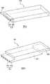
图3为根据本发明之一种光导引装置300之立体图,该光导引装置300包含入射部份310;漫射部份320以及檐顶330;其中入射部份310包含发光源340以及入射区350。入射部份310系连接于漫射部份320,且入射部份310系位于光导引装置300之一角。檐顶330位于入射部分310之上方,檐顶330之表面与漫射部分320之表面形成光导引装置300之表面。漫射部份320具有一致的厚度。而入射区350所包含之发光源340可由一个或多个发光二极管(LED)所组成。3 is a perspective view of a light guiding
发光源340发出光线,经过入射部份310进入漫射部份320。除此之外,由于檐顶330连接于漫射部分320,由漫射部分320漫反射的光线进入檐顶330,并由檐顶330底面的漫射结构漫反射并由上表面均匀射出。因此本发明之光导引装置300的有效发光区极为其整个表面,且仅需配置一发光源340,可达到节省成本及有效利用光导引装置300之功效。The
图4为根据本发明之另一种光导引装置400之立体图,该光导引装置400与上述之光导引装置300相似,不同处为光导引装置400具有二个入射部份410a、410b及二个檐顶430a、430b,分别配置于光导引装置400之二对角,以使光导引装置400提供一更均匀照明。Fig. 4 is a perspective view of another light guiding
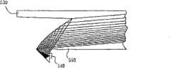
图5为根据本发明另丨种光导引装置500之实施例之立体图。光导引装置500与上述之光导引装置300相似,其中之不同处在于光导引装置500之入射区550之上表面为抛物面。如图6所示,图6为光导装置500之入射部分510之放大图,发光源540利用入射区510之抛物面将光反射,光经反射后进入漫射部分520。经反射之入射光线可使光导引装置500之整个表面发光,并可提供均匀的光源并使光在入射部分的耦合效率提高,从而提高光能利用效率。FIG. 5 is a perspective view of an embodiment of another light guiding
图7为根据本发明之另一种光导引装置700之立体图,该光导引装置700与上述之光导引装置500相似,不同处为光导引装置700具有二个入射部份710a、710b及二个檐顶730a、730b,分别配置于光导引装置700之二对角,以使光导引装置700提供一更均匀照明。7 is a perspective view of another light guiding
图8为根据本发明之另一种光导引装置800之立体图,该光导引装置800包含入射部份810;漫射部份820以及檐顶830;其中入射部份810包含至少一个发光源840以及入射区850,且发光源840分别可由一个或多个LED所组成。入射部份810系连接于漫射部份820,且入射部份810系位于光导引装置800之一边。檐顶830位于入射部分810之上方,檐顶830之表面与漫射部分820之表面形成光导引装置800之表面。漫射部份820具有一致的厚度。Fig. 8 is a perspective view of another
发光源840发出光线,经过入射部份810进入漫射部份820。除此之外,由于檐顶830连接于漫射部分820,由漫射部分820漫反射的光线进入檐顶830,并由檐顶830底面的漫射结构漫反射并由上表面均匀射出。因此本发明之光导引装置800的有效发光区极为其整个表面,可达到有效利用光导引装置800之功效。The
图9为根据本发明之另一种光导引装置900之立体图,该光导引装置900包含入射部份910;漫射部份920以及檐顶930;其中入射部份910包含至少一个发光源940以及入射区950,且发光源940分别可由一个或多个LED所组成。入射部份910系连接于漫射部份920,且入射部份910系位于光导引装置900之一边。檐顶930位于入射部分910之对边与漫射部份920,檐顶930之表面与漫射部分920之表面形成光导引装置900之表面。漫射部份920具有一致的厚度。Fig. 9 is a perspective view of another
光导引装置900之漫射部份920具有一致的厚度,使其容易组装且不需高精准度制造,可有效地降低制造成本。且檐顶930连接于漫射部分920,由漫射部分920漫反射的光线进入檐顶930,并由檐顶930底面的漫射结构漫反射并由上表面均匀射出,使光导引装置900之有效发光区不被缩限。The
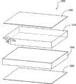
图10为根据本发明之一种背光装置1000之立体图。该背光装置1000包含光导装置1010;漫射装置1020以及反射装置1030。其中所显示之光导装置1010即为光导装置300,亦可为上述光导装置中之任何一种。如图10所示,漫射装置1020位于光导装置1010之上,光导装置1010位于反射装置1030之上。由光导装置1010向各方向射出之光,可被反射装置1030反射至漫射装置1020,或直接射向漫射装置1020,再经漫射装置1020射出。背光装置1000另可包含侧边反射装置1040,用于提高光能利用效率,使由光导装置1010射出的光可均匀的反射至漫射装置1020。FIG. 10 is a perspective view of a
图11为根据本发明之一种多区块背光装置1100之立体图,包含9个如上述之背光装置1000。多区块背光装置1100藉由拼装复数个背光装置1000以配合所需尺寸之不同,且由于背光装置1000之形状平整,使得拼装得以简单的达成。图11中仅显示利用光导装置300之背光装置1000所形成之多区块背光装置1100,但其中之光导装置亦可为光导装置300、400、500、700或800。FIG. 11 is a perspective view of a
图12为根据本发明之另一种多区块背光装置1200之立体图,包含6个光导引装置900所形成之背光装置1000。多区块背光装置1200藉由拼装复数个背光装置1000以配合所需尺寸之不同,且由于背光装置1000之形状平整,使得拼装得以简单的达成。FIG. 12 is a perspective view of another multi-block backlight device 1200 according to the present invention, which includes a
虽然本发明的技术内容与特征如上所述,然而,所属领域的技术人员仍可在不背离本发明的教示与揭示内容的情况下进行许多变化与修改。因此,本发明的范围并非限定于已揭示的实施例,而包含不背离本发明的其它变化与修改,其为如所附权利要求书所涵盖的范围。Although the technical content and features of the present invention are as described above, those skilled in the art can make many changes and modifications without departing from the teaching and disclosure of the present invention. Accordingly, the scope of the present invention is not limited to the disclosed embodiments, but includes other changes and modifications without departing from the invention, which are covered by the appended claims.
Claims (24)
Priority Applications (2)
| Application Number | Priority Date | Filing Date | Title |
|---|---|---|---|
| CNA2007100976517ACN101295054A (en) | 2007-04-27 | 2007-04-27 | Eave top light guiding device and backlight device using the same |
| US12/107,893US20080266903A1 (en) | 2007-04-27 | 2008-04-23 | Eave light guiding device and backlight device using the same |
Applications Claiming Priority (1)
| Application Number | Priority Date | Filing Date | Title |
|---|---|---|---|
| CNA2007100976517ACN101295054A (en) | 2007-04-27 | 2007-04-27 | Eave top light guiding device and backlight device using the same |
Publications (1)
| Publication Number | Publication Date |
|---|---|
| CN101295054Atrue CN101295054A (en) | 2008-10-29 |
Family
ID=39886756
Family Applications (1)
| Application Number | Title | Priority Date | Filing Date |
|---|---|---|---|
| CNA2007100976517APendingCN101295054A (en) | 2007-04-27 | 2007-04-27 | Eave top light guiding device and backlight device using the same |
Country Status (2)
| Country | Link |
|---|---|
| US (1) | US20080266903A1 (en) |
| CN (1) | CN101295054A (en) |
Cited By (3)
| Publication number | Priority date | Publication date | Assignee | Title |
|---|---|---|---|---|
| CN102081187A (en)* | 2010-11-30 | 2011-06-01 | 深圳市华星光电技术有限公司 | Spliced type light guide plate structure and backlight module |
| CN103472524A (en)* | 2013-09-13 | 2013-12-25 | 北京京东方光电科技有限公司 | Light guide plate and backlight module |
| CN103620456A (en)* | 2011-04-28 | 2014-03-05 | 赤多尼科德累斯顿两合股份有限公司 | Lighting device with OLED or QLED |
Families Citing this family (4)
| Publication number | Priority date | Publication date | Assignee | Title |
|---|---|---|---|---|
| CN102224372B (en)* | 2008-11-25 | 2013-07-24 | 夏普株式会社 | Illumination device, display device, and television reception device |
| US20110090676A1 (en)* | 2009-10-16 | 2011-04-21 | Patrick Sortor | Illuminated Decorative Trim Assembly |
| US9133989B2 (en)* | 2012-12-15 | 2015-09-15 | Lumenetix, Inc. | Mechanical attachment system for linear light modules |
| CN204945422U (en)* | 2015-09-29 | 2016-01-06 | 北京京东方茶谷电子有限公司 | Light guide plate, backlight module and wearable device |
Family Cites Families (3)
| Publication number | Priority date | Publication date | Assignee | Title |
|---|---|---|---|---|
| US6712481B2 (en)* | 1995-06-27 | 2004-03-30 | Solid State Opto Limited | Light emitting panel assemblies |
| JP4420813B2 (en)* | 2004-12-28 | 2010-02-24 | 株式会社エンプラス | Surface light source device and display device |
| US20080037284A1 (en)* | 2006-04-21 | 2008-02-14 | Rudisill Charles A | Lightguide tile modules and modular lighting system |
- 2007
- 2007-04-27CNCNA2007100976517Apatent/CN101295054A/enactivePending
- 2008
- 2008-04-23USUS12/107,893patent/US20080266903A1/ennot_activeAbandoned
Cited By (4)
| Publication number | Priority date | Publication date | Assignee | Title |
|---|---|---|---|---|
| CN102081187A (en)* | 2010-11-30 | 2011-06-01 | 深圳市华星光电技术有限公司 | Spliced type light guide plate structure and backlight module |
| CN103620456A (en)* | 2011-04-28 | 2014-03-05 | 赤多尼科德累斯顿两合股份有限公司 | Lighting device with OLED or QLED |
| CN103472524A (en)* | 2013-09-13 | 2013-12-25 | 北京京东方光电科技有限公司 | Light guide plate and backlight module |
| CN103472524B (en)* | 2013-09-13 | 2016-08-17 | 北京京东方光电科技有限公司 | A kind of light guide plate and backlight module |
Also Published As
| Publication number | Publication date |
|---|---|
| US20080266903A1 (en) | 2008-10-30 |
Similar Documents
| Publication | Publication Date | Title |
|---|---|---|
| CN101788120B (en) | Backlight assembly and display apparatus having the same | |
| TWI522571B (en) | Lighting device | |
| CN100543552C (en) | Backlight module and liquid crystal display device | |
| TW200424695A (en) | Backlight module of LED | |
| CN101295054A (en) | Eave top light guiding device and backlight device using the same | |
| WO2011066692A1 (en) | Uniform high-luminance side-light type backlight source | |
| TWI522572B (en) | Lighting device | |
| TWI356238B (en) | Backlight module and liquid crystal display using | |
| US9117379B2 (en) | Backlight unit, display using the same and lighting system including the same | |
| TWM466278U (en) | Thinized direct type LED backlight module | |
| CN103968300A (en) | Backlight source and display device | |
| CN110398858A (en) | Reflective lampshade of a backlight module | |
| TW201416771A (en) | Backlight module | |
| CN203744043U (en) | Backlight module and display device | |
| WO2019205476A1 (en) | Light source module, backlight module, and liquid crystal display device | |
| CN201706328U (en) | A light source assembly and its lighting device and backlight module | |
| CN1773350A (en) | liquid crystal display device | |
| CN106989289B (en) | Direct type LED panel lamp | |
| CN202327857U (en) | High-brightness and ultra-thin backlight source | |
| TWI358004B (en) | Backlight module | |
| TWM467800U (en) | Direct lighting type illumination device with flat-type | |
| CN2876546Y (en) | Light guiding plate | |
| TWI385819B (en) | Illumination system employng led and led thereof | |
| CN207992641U (en) | A side-entry backlight module structure without a light guide plate | |
| JP3205851U (en) | Lighting fixture |
Legal Events
| Date | Code | Title | Description |
|---|---|---|---|
| C06 | Publication | ||
| PB01 | Publication | ||
| C10 | Entry into substantive examination | ||
| SE01 | Entry into force of request for substantive examination | ||
| C12 | Rejection of a patent application after its publication | ||
| RJ01 | Rejection of invention patent application after publication | Application publication date:20081029 |