CN101292921A - Compression device with S-shaped bladder - Google Patents
Compression device with S-shaped bladderDownload PDFInfo
- Publication number
- CN101292921A CN101292921ACNA2008100909907ACN200810090990ACN101292921ACN 101292921 ACN101292921 ACN 101292921ACN A2008100909907 ACNA2008100909907 ACN A2008100909907ACN 200810090990 ACN200810090990 ACN 200810090990ACN 101292921 ACN101292921 ACN 101292921A
- Authority
- CN
- China
- Prior art keywords
- sleeve
- bladder
- opening
- openings
- inner layer
- Prior art date
- Legal status (The legal status is an assumption and is not a legal conclusion. Google has not performed a legal analysis and makes no representation as to the accuracy of the status listed.)
- Granted
Links
Images


Classifications
- A—HUMAN NECESSITIES
- A61—MEDICAL OR VETERINARY SCIENCE; HYGIENE
- A61H—PHYSICAL THERAPY APPARATUS, e.g. DEVICES FOR LOCATING OR STIMULATING REFLEX POINTS IN THE BODY; ARTIFICIAL RESPIRATION; MASSAGE; BATHING DEVICES FOR SPECIAL THERAPEUTIC OR HYGIENIC PURPOSES OR SPECIFIC PARTS OF THE BODY
- A61H9/00—Pneumatic or hydraulic massage
- A61H9/005—Pneumatic massage
- A61H9/0078—Pneumatic massage with intermittent or alternately inflated bladders or cuffs
- A—HUMAN NECESSITIES
- A61—MEDICAL OR VETERINARY SCIENCE; HYGIENE
- A61F—FILTERS IMPLANTABLE INTO BLOOD VESSELS; PROSTHESES; DEVICES PROVIDING PATENCY TO, OR PREVENTING COLLAPSING OF, TUBULAR STRUCTURES OF THE BODY, e.g. STENTS; ORTHOPAEDIC, NURSING OR CONTRACEPTIVE DEVICES; FOMENTATION; TREATMENT OR PROTECTION OF EYES OR EARS; BANDAGES, DRESSINGS OR ABSORBENT PADS; FIRST-AID KITS
- A61F13/00—Bandages or dressings; Absorbent pads
- A61F13/06—Bandages or dressings; Absorbent pads specially adapted for feet or legs; Corn-pads; Corn-rings
- A61F13/08—Elastic stockings; for contracting aneurisms
- A61F13/085—Openable readjustable
- A—HUMAN NECESSITIES
- A61—MEDICAL OR VETERINARY SCIENCE; HYGIENE
- A61H—PHYSICAL THERAPY APPARATUS, e.g. DEVICES FOR LOCATING OR STIMULATING REFLEX POINTS IN THE BODY; ARTIFICIAL RESPIRATION; MASSAGE; BATHING DEVICES FOR SPECIAL THERAPEUTIC OR HYGIENIC PURPOSES OR SPECIFIC PARTS OF THE BODY
- A61H9/00—Pneumatic or hydraulic massage
- A61H9/005—Pneumatic massage
- A61H9/0078—Pneumatic massage with intermittent or alternately inflated bladders or cuffs
- A61H9/0092—Cuffs therefor
- A—HUMAN NECESSITIES
- A61—MEDICAL OR VETERINARY SCIENCE; HYGIENE
- A61H—PHYSICAL THERAPY APPARATUS, e.g. DEVICES FOR LOCATING OR STIMULATING REFLEX POINTS IN THE BODY; ARTIFICIAL RESPIRATION; MASSAGE; BATHING DEVICES FOR SPECIAL THERAPEUTIC OR HYGIENIC PURPOSES OR SPECIFIC PARTS OF THE BODY
- A61H2201/00—Characteristics of apparatus not provided for in the preceding codes
- A61H2201/16—Physical interface with patient
- A61H2201/1683—Surface of interface
- A61H2201/169—Physical characteristics of the surface, e.g. material, relief, texture or indicia
- A61H2201/1697—Breathability of the material
- A—HUMAN NECESSITIES
- A61—MEDICAL OR VETERINARY SCIENCE; HYGIENE
- A61H—PHYSICAL THERAPY APPARATUS, e.g. DEVICES FOR LOCATING OR STIMULATING REFLEX POINTS IN THE BODY; ARTIFICIAL RESPIRATION; MASSAGE; BATHING DEVICES FOR SPECIAL THERAPEUTIC OR HYGIENIC PURPOSES OR SPECIFIC PARTS OF THE BODY
- A61H2205/00—Devices for specific parts of the body
- A61H2205/10—Leg
- A61H2205/106—Leg for the lower legs
- A—HUMAN NECESSITIES
- A61—MEDICAL OR VETERINARY SCIENCE; HYGIENE
- A61H—PHYSICAL THERAPY APPARATUS, e.g. DEVICES FOR LOCATING OR STIMULATING REFLEX POINTS IN THE BODY; ARTIFICIAL RESPIRATION; MASSAGE; BATHING DEVICES FOR SPECIAL THERAPEUTIC OR HYGIENIC PURPOSES OR SPECIFIC PARTS OF THE BODY
- A61H2205/00—Devices for specific parts of the body
- A61H2205/10—Leg
- A61H2205/108—Leg for the upper legs
- A—HUMAN NECESSITIES
- A61—MEDICAL OR VETERINARY SCIENCE; HYGIENE
- A61H—PHYSICAL THERAPY APPARATUS, e.g. DEVICES FOR LOCATING OR STIMULATING REFLEX POINTS IN THE BODY; ARTIFICIAL RESPIRATION; MASSAGE; BATHING DEVICES FOR SPECIAL THERAPEUTIC OR HYGIENIC PURPOSES OR SPECIFIC PARTS OF THE BODY
- A61H2209/00—Devices for avoiding blood stagnation, e.g. Deep Vein Thrombosis [DVT] devices
Landscapes
- Health & Medical Sciences (AREA)
- Animal Behavior & Ethology (AREA)
- Veterinary Medicine (AREA)
- Public Health (AREA)
- General Health & Medical Sciences (AREA)
- Life Sciences & Earth Sciences (AREA)
- Rehabilitation Therapy (AREA)
- Physical Education & Sports Medicine (AREA)
- Pain & Pain Management (AREA)
- Epidemiology (AREA)
- Engineering & Computer Science (AREA)
- Biomedical Technology (AREA)
- Heart & Thoracic Surgery (AREA)
- Vascular Medicine (AREA)
- Orthopedics, Nursing, And Contraception (AREA)
- Massaging Devices (AREA)
- Professional, Industrial, Or Sporting Protective Garments (AREA)
Abstract
Description
Translated fromChinese技术领域technical field
本发明总的来说涉及一种用来向穿戴者的身体部分施加加压治疗的加压装置,更具体地说,涉及一种加压套。The present invention relates generally to a compression device for applying compression therapy to a body part of a wearer, and more particularly, to a compression sleeve.
技术背景technical background
对于不能移动的患者以及其他人员来说关心的主要的问题是形成诸如深静脉血栓(DVT)和周边水肿等的血液中的凝块的医疗情况。这些患者和人员包括那些正在进行外科手术、麻醉手术、长期卧床休息等的那些人。这些血液发生凝块的情况通常发生在下肢和/或骨盆的深静脉中。诸如肠骨、股骨、popiteal和胫骨等的这些静脉将除去氧气的血液返回到心脏。例如,当由于疾病、受伤或者不活动而使这些静脉中的血液循环受阻时,就存在血液积聚或者汇聚的趋势。血液静态汇聚可能导致血液凝块的形成。与这种情况相关联的主要风险是干扰心脏血管的循环。更严重的是,血液凝块的碎片能破裂松开并迁移。肺部栓子可由潜在阻塞主肺部动脉的碎片形成,这种情况可能是对生命有威胁的。本发明也能应用于淋巴水肿的治疗。Of major concern to immobile patients and others are medical conditions that form clots in the blood such as deep vein thrombosis (DVT) and peripheral edema. These patients and persons include those undergoing surgery, procedures under anesthesia, prolonged bed rest, and the like. These blood clots usually occur in the deep veins of the lower extremities and/or pelvis. These veins, such as the iliac, femoral, popiteal, and tibial, return deoxygenated blood to the heart. For example, when blood circulation in these veins is obstructed due to illness, injury, or inactivity, there is a tendency for blood to pool or pool. Static pooling of blood may lead to the formation of blood clots. The main risk associated with this condition is interference with the circulation of the heart vessels. More seriously, fragments of the blood clot can break loose and migrate. Pulmonary emboli can form from debris potentially blocking the main pulmonary artery, a potentially life-threatening condition. The invention can also be applied to the treatment of lymphedema.
与患者不能活动相关联的情况和导致的风险,可以通过向患者的诸如腿等肢体施加间歇压力以帮助血液循环而得以控制或者减轻。例如,连续加压装置已经在使用了,诸如授给Hasty的美国专利第4,091,864中公开的装置。连续加压装置一般由两片材料构成,这两片材料在接合处固定在一起,限定了一个或者多个不透流体的囊,不透流体的囊连接到压力源,用于在患者身体部分的周围施加连续压力,以改善血液返回心脏。可膨胀部覆盖有薄板,以提高使用期限并保护不被刺破。作为加压装置的部件,这两个片材在结构上设计成在反复使用的情况下承受长时间的压力变化。Conditions and resulting risks associated with patient immobility can be controlled or mitigated by applying intermittent pressure to the patient's extremities, such as legs, to aid blood circulation. For example, continuous pressurization devices have been used, such as that disclosed in US Patent No. 4,091,864 to Hasty. Continuous compression devices are generally constructed of two sheets of material held together at a joint to define one or more fluid-tight bladders connected to a pressure source for use in the patient's body Continuous pressure is applied around the body to improve blood return to the heart. The inflatable part is covered with a thin plate to increase longevity and protect against punctures. As part of the pressurization device, the two sheets are structurally designed to withstand long-term pressure changes with repeated use.
片材的不透过性使患者不舒服,因为潮气(即排汗)被困在不可透过的片材和患者身体部分之间。这导致患者不愿意穿戴这种套,由此,对患者的健康造成危险。而且,这种套通常没有延展性而且笨重,因为这些囊在治疗过程中必须能够保持相当大的流体压力。因此,现有技术的套限制了患者的运动能力。还有,因为在压力下这种现有技术设计把可膨胀囊保持在固定位置,所以可能使患者肢体皮肤发炎。随着治疗过程中的压力变化,这些囊在患者肢体上加压或者松开,摩擦并使皮肤发炎。在一个加压周期中囊会发皱或者折叠,这可能造成进一步疼痛。现有套的最终构造是笨重的、坚硬的,对于长期使用的人员来说可能会感觉到重。本发明旨在解决上面提及的缺陷,而不会损及使用期限和临床效果。The impermeability of the sheet is uncomfortable for the patient because moisture (ie, perspiration) is trapped between the impermeable sheet and the patient's body part. This leads to the reluctance of the patient to wear such a cover, thereby posing a risk to the patient's health. Furthermore, such sleeves are generally inflexible and bulky since the bladders must be able to maintain considerable fluid pressure during treatment. Thus, prior art sleeves limit the patient's ability to move. Also, because this prior art design maintains the inflatable bladder in a fixed position under pressure, it may irritate the patient's extremity skin. As the pressure changes during treatment, these sacs compress or loosen on the patient's limb, rubbing and inflaming the skin. During a compression cycle the bursa can crease or fold, which can cause further pain. The resulting construction of existing sleeves is bulky, rigid, and may feel heavy to personnel who use them for extended periods of time. The present invention aims to solve the drawbacks mentioned above without compromising the shelf life and clinical effect.
如上所述,现有技术的装置是针对使用期限和强度构造的。如授给Tordella的美国专利公开第2005/0187503A1所显示的,Tordella描述了一种带顶、底片材的套。这些片材在周边处被固定而形成可膨胀部或者囊,如图2所示。形成腔或囊的材料是聚氯乙烯或聚乙烯。这些材料对于潮气是不能透过的,因为它们需要是流体密封的而且要厚到足以承受数千次加压周期而不裂开。当该装置提供置于套周围的通气孔时,Tordella提供了一些冷却。还有,穿过这些片材引入了一个狭缝,但是,Tordella的狭缝不是在由腔(即囊)限定的区域里面。总的说来,通向皮肤的通道将提供在开口处收集的体液的蒸发,但是Tordella的发明没有考虑到除去困在离开开口处的没有透过性片材下面的流体。蒸发限制在开口处以及靠近开口处没有透过性片材下面紧挨着的区域。本发明的至少一些实施例,如下所述通过将流体从没有透过性片材下面以足够的速率移动到多个位置、尺寸和形状能够保持血液流动并蒸发潮气的开口,提供了针对被困住流体的问题的解决方案。Tordella套结构类似于Model 9529 SCD Express装置(膝部长度套),这种装置可以在美国从Tyco Healthcare Group L.P.得到,这将在下面更详细地讨论。As noted above, prior art devices are constructed for longevity and strength. As shown in US Patent Publication No. 2005/0187503A1 to Tordella, Tordella describes a case with top and bottom sheets. These sheets are secured at the perimeter to form an inflatable portion or bladder, as shown in FIG. 2 . The material forming the cavity or bladder is polyvinyl chloride or polyethylene. These materials are impermeable to moisture because they need to be fluid tight and thick enough to withstand thousands of pressurization cycles without cracking. The Tordella provides some cooling while the unit offers vent holes placed around the sleeve. Also, a slit is introduced through the sheets, however, the Tordella's slit is not within the area defined by the cavity (ie pocket). In general, the passage to the skin will provide evaporation of bodily fluids collected at the opening, but Tordella's invention does not allow for the removal of fluid trapped under the impermeable sheet exiting the opening. Evaporation is limited to the opening and the area immediately below the impermeable sheet near the opening. At least some embodiments of the present invention, as described below, provide protection against trapped The solution to the problem of living fluids. The Tordella sleeve construction is similar to the Model 9529 SCD Express device (knee length sleeve), which is available in the United States from Tyco Healthcare Group L.P., which is discussed in more detail below.
还有其他的现有技术试图通过透气能力和蒸发改善舒适性。授给Nicholas的美国专利第3,824,492说的是一种外衣,能够对下肢提供脉动压力。多个孔被设置在脚趾区域。经该装置被穿戴时提供的空气空间,进入孔的空气被拉着经过患者皮肤。Nicholas具有硬外壳。Nicholas装置具有本发明中没有发现的多个缺点。本发明至少一些实施例的加压套在内层和外层处是有弹性的,以改善患者运动性和伸展性。取代象Nicholas的硬外壳是,本发明在一些实施例中具有可透气的、柔软的而且有弹性的外覆层。本发明的弹性外覆层帮助套在压力下贴合肢体。本发明没有用作在皮肤处使空气移动经过皮肤并进入周围环境的通路的结构。Still other prior art attempts to improve comfort through breathability and evaporation. US Patent No. 3,824,492 to Nicholas describes a garment that provides pulsating pressure to the lower extremities. Holes are provided in the toe area. Air entering the apertures is drawn across the patient's skin through the air space provided when the device is worn. Nicholas has a hard shell. The Nicholas device has several disadvantages not found in the present invention. The compression sleeves of at least some embodiments of the present invention are elastic at the inner and outer layers to improve patient mobility and stretch. Instead of a hard shell like Nicholas, the present invention in some embodiments has a breathable, soft and resilient outer cover. The elastic outer cover of the present invention helps the sleeve conform to the limb under pressure. The present invention has no structure at the skin that acts as a pathway for air to move through the skin and into the surrounding environment.
Hasty(美国专利第4,091,804)和Annis(美国专利第4,207,876)公开了与通气通路连通的多个开口。空气在压缩机的作用下被强制通过通路和开口到达皮肤。本发明没有在套的层中使用通气通路。而且,在本发明的优选实施例中,加压套没有使用压缩机强制空气通过开口经通路到达皮肤。在本发明的优选实施例中,开口处的空气与芯吸材料接合,象下面更充分描述的那样蒸发芯吸的潮气。在本发明中,输送机构可以是芯吸材料。象Jacobs(美国专利第5,489,259)考虑了直接通向一部分患者肢体的通道,但Jacobs装置的问题是冷却(蒸发)被限制在局部的开口中。Neal文献(美国专利第5,693,453)描述了各种几何形状的开口,但是,尺寸、形状和分布是方便使用的问题。Neal装置没有谈到预防治疗。Hasty (US Patent No. 4,091,804) and Annis (US Patent No. 4,207,876) disclose a plurality of openings in communication with the vent passage. Air is forced by the compressor through the channels and openings to the skin. The present invention does not use vent channels in the layers of the sleeve. Also, in a preferred embodiment of the invention, the compression sleeve does not use a compressor to force air through the openings through the passageway to the skin. In a preferred embodiment of the invention, the air at the opening engages the wicking material to evaporate the wicked moisture as described more fully below. In the present invention, the delivery mechanism may be a wicking material. Like Jacobs (US Pat. No. 5,489,259) contemplates access directly to a portion of the patient's limb, but the problem with the Jacobs device is that the cooling (evaporation) is confined to the partial opening. The Neal reference (US Patent No. 5,693,453) describes openings of various geometries, however, size, shape and distribution are matters of convenience. The Neal device doesn't talk about prophylaxis.
透气性与经蒸发冷却相关联,因为空气必须被允许流经开口到达皮肤。如果一种装置能经其外层透气,那么能发生更快的蒸发。经外层透气是所引用的文献中没有解决的问题。多个引用文献提到透气以避免汗积聚,但没有一个文献谈到使用连续加压提供预防治疗。授给Hall的装置(美国专利第6,520,926)描述了一种能透气的支撑短袜,但Hall没有对如何使其透气提供额外的细节。授给Roth的装置(美国专利第7,044,924)描述说,各种尺寸的孔可以在相邻的接合处234或者242之间穿过内、外片材202/204冲出,以考虑通气。进一步,为了舒适,潮气芯吸衬里材料可以施加到内片材204的表面。横向接合处230、232、234和纵向接合处238、240形成了多个可膨胀囊250。本申请人使其内片材适合于提供芯吸性质,因为本申请人发现向片材层叠或者施加芯吸材料可能损及材料的芯吸能力。由于层叠,芯吸材料的纤维可能会中断,变得不连续;因此,如下所述干扰了芯吸纤维的毛细作用。Breathability is associated with evaporative cooling because air must be allowed to flow through the openings to the skin. If a device is breathable through its outer layer, faster evaporation can occur. Breathing through the outer layer is a problem not addressed in the cited literature. Multiple citations mention ventilation to avoid sweat buildup, but none of the literature mentions the use of continuous compression to provide prophylactic treatment. The device to Hall (US Patent No. 6,520,926) describes a breathable support sock, but Hall provides no additional details on how to make it breathable. The device to Roth (US Patent No. 7,044,924) describes that holes of various sizes can be punched through the inner and outer sheets 202/204 between
Roth可能在囊附件引入低压区域,该区域已经被证明促进血液汇聚。本申请人特别地构建了其装置的至少一些实施例,通过构造相邻囊以使相邻囊之间的低压区域最小,来避免血液汇聚。申请人的装置如下所述被证明维持了临床功效。Roth没有提供有关其装置临床功效的任何信息,也没有提供任何的图来显示其开口或者芯吸材料。授给Linnane的短袜装置(美国专利公开第2006/0010574)描述了一种加压短袜,该加压短袜在人员皮肤附件带有芯吸材料,用于沿着通路把潮气吸到短袜的外面。本发明把潮气引向尺寸、形状、沿着加压装置的位置用于最大化蒸发同时保持临床功效的多个开口。Roth may have introduced an area of low pressure near the sac that has been shown to promote blood pooling. Applicants have specifically constructed at least some embodiments of their devices to avoid pooling of blood by configuring adjacent balloons to minimize low pressure areas between adjacent balloons. Applicants' device was demonstrated to maintain clinical efficacy as described below. Roth did not provide any information about the clinical efficacy of its device, nor did it provide any diagrams showing its opening or wicking material. The sock device issued to Linnane (U.S. Patent Publication No. 2006/0010574) describes a compression sock with wicking material near the skin of the person for drawing moisture along the pathway into the sock. the outside of the sock. The present invention directs moisture to multiple openings that are sized, shaped, and positioned along the pressurized device to maximize evaporation while maintaining clinical efficacy.
弹性在现有技术中可以被发现并被普遍理解成加压短袜的一个重要好处,加压短袜诸如
本发明帮助克服了患者的不舒适而没有减少临床效果,如在本申请中公开的支持用实验室测试所显示的那样。一个重要的目的是改进患者的顺从性,其被定义为使用医生开出的套。患者的顺从性和患者的舒适性有直接的相关性。使用机械加压装置的顺从性一直都是保健中关切的问题。医务人员由于患者负担和责任而过度劳累,因此,一对一照顾患者时间是特别珍贵的。经常有报告说,患者穿戴加压套会变得不舒服并要求拿掉这些套,即使这些套可能对防止出现致命的肺部栓子来说是必须的。义务人员可能没有时间充分地教育患者关于穿戴这种套的重要性,而且可能没有时间确保患者一直穿戴这种套。例如,CMAJ Clinical Practice Guidelines for the Care and Treatment ofBreast Cancer进行的调查研究,讨论了治疗与乳癌相关联的淋巴水肿。研究表明,因为这些装置一般难以使用而且不舒服,所以患者是不顺从的。这就是加压套生产商们正尝试维持已经在现有技术中发现的临床功效的同时引进更舒适的套的原因。由于需要更短时间地呆在医院里并且更多门诊患者的外科手术,对维持临床功效的同时更容易使用的更舒适装置的需要,是本领域中长期存在着的需要。The present invention helps overcome patient discomfort without diminishing the clinical effect, as shown by the supporting laboratory tests disclosed in this application. An important objective is to improve patient compliance, which is defined as use of a physician-prescribed sleeve. There is a direct correlation between patient compliance and patient comfort. Compliance with the use of mechanical compression devices has always been a concern in healthcare. Medical staff are overworked due to patient burden and responsibility, therefore, one-on-one patient care time is especially precious. There are frequent reports that patients become uncomfortable wearing compression sleeves and ask to remove them, even though they may be necessary to prevent fatal pulmonary emboli. Volunteers may not have time to adequately educate patients about the importance of wearing such covers, and may not have time to ensure that patients wear such covers at all times. For example, a survey conducted by the CMAJ Clinical Practice Guidelines for the Care and Treatment of Breast Cancer discusses the treatment of lymphedema associated with breast cancer. Research has shown that patients are noncompliant because these devices are generally difficult and uncomfortable to use. This is why compression sleeve manufacturers are attempting to introduce more comfortable sleeves while maintaining the clinical efficacy already found in the prior art. With shorter hospital stays and more outpatient surgical procedures, the need for more comfortable devices that are easier to use while maintaining clinical efficacy is a long-felt need in the art.
如上所述,存在着长期需要但没有在现有技术中发现的改善舒适性而不损及临床效果的套。市场上其他的现有技术装置,诸如

在优选实施例中的本发明被设计成,在最小化对血液流动增加或者临床功效的任何负面影响的同时,提供最大蒸发量。蒸发量是芯吸材料、开口尺寸、位置和形状的函数。血液流动依赖于开口尺寸、形状和位置,即开口性质必须被最小化为不干扰血液流动,同时最大化在没有透过性的层下面被困住的潮气的蒸发。The present invention in a preferred embodiment is designed to provide maximum evaporation while minimizing any negative impact on blood flow enhancement or clinical efficacy. Evaporation is a function of wicking material, opening size, location and shape. Blood flow is dependent on opening size, shape and location, ie the opening properties must be minimized so as not to interfere with blood flow while maximizing evaporation of moisture trapped beneath the impermeable layer.
象本领域中已知的那样,加压套用来向穿戴者的身体部分提供预防治疗。这种治疗是通过沿着肢体向着心脏以级联方式增加血液速度,帮助防止形成血液凝块。本发明图示和描述的实施例包裹在患者肢体的整个周长。本发明并不限于整个包裹式装置。能够实现下述特征的结构变化将增强现有技术装置的舒适性和使用,但不一定以它们声称的临床功效为代价。As is known in the art, compression sleeves are used to provide prophylactic treatment to a part of the wearer's body. This treatment helps prevent blood clots from forming by increasing the velocity of blood in a cascading fashion along the limb toward the heart. The illustrated and described embodiment of the invention wraps around the entire circumference of the patient's limb. The present invention is not limited to the entire wrap-around device. Structural changes enabling the features described below would enhance the comfort and use of prior art devices, but not necessarily at the expense of their claimed clinical efficacy.
发明内容Contents of the invention
在本发明的一个方面中,一种用于对穿戴者身体上的部位进行加压治疗的装置大体包括至少一个可膨胀的囊。所述囊具有大体S形的形状,至少带有流体连通的分开的第一和第二部分。至少一个开口形成在所述第一和第二部分之间。In one aspect of the invention, an apparatus for applying compression therapy to a body part of a wearer generally includes at least one inflatable bladder. The bladder has a generally S-shape with at least separate first and second portions in fluid communication. At least one opening is formed between the first and second portions.
在下文,其他的特征将会部分地明了,并且部分地被指出来。Other features will be in part apparent and in part pointed out hereinafter.
附图说明Description of drawings
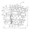
图1是加压套一个实施例的前视图,该加压套中,套的外覆层和中间层被部分去掉以显示下面的层;Figure 1 is a front view of one embodiment of a compression sleeve in which the outer cover and intermediate layer of the sleeve are partially removed to reveal the underlying layers;
图2是加压套的分解立体图;Fig. 2 is an exploded perspective view of the pressure sleeve;
图3是加压套内层的后视图;Fig. 3 is the rear view of the inner layer of the pressure sleeve;
图4是外覆层被去掉的加压套的前视图;Figure 4 is a front view of the compression sleeve with the outer coating removed;
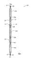
图5是套的可膨胀囊为膨胀状态的加压套的纵向剖视图;Figure 5 is a longitudinal sectional view of the compression sleeve with the inflatable bladder of the sleeve in an inflated state;
图6是套的可膨胀囊为收缩状态的加压套的纵向剖视图;Figure 6 is a longitudinal sectional view of the compression sleeve with the inflatable bladder of the sleeve in a deflated state;
图7是外覆层的局部放大视图,图示了环材料;Figure 7 is an enlarged fragmentary view of the outer cover illustrating the ring material;
图8是加压套另一实施例的分解立体图;Fig. 8 is an exploded perspective view of another embodiment of the compression sleeve;
图9是外覆层被去掉的图8加压套的前视图;Figure 9 is a front view of the compression sleeve of Figure 8 with the outer coating removed;
图10是加压套另一实施例的分解立体图;Fig. 10 is an exploded perspective view of another embodiment of the compression sleeve;
图11是外覆层被去掉的图10加压套的前视图;Figure 11 is a front view of the compression sleeve of Figure 10 with the outer coating removed;
图12是外覆层被去掉的、与图11实施例类似的加压套另一实施例的前视图;Figure 12 is a front view of another embodiment of a compression sleeve similar to the embodiment of Figure 11 with the outer covering removed;
图13是加压套另一实施例的前视图;Figure 13 is a front view of another embodiment of the compression sleeve;
图14是加压套另一实施例的前视图,其中,外覆层被部分去掉以显示中间层和内层;Figure 14 is a front view of another embodiment of a compression sleeve with the outer cover partially removed to reveal the middle and inner layers;
图15是加压套又一实施例的前视图,其中,外覆层被部分去掉以显示中间层和内层;Figure 15 is a front view of yet another embodiment of a compression sleeve with the outer cover partially removed to reveal the middle and inner layers;
图16是类似于图5的加压套另一实施例的剖视图,其中,套的组件沿着周边接合线被固定在一起;16 is a cross-sectional view similar to that of FIG. 5 of another embodiment of the compression sleeve, wherein the components of the sleeve are secured together along a peripheral seam line;
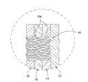
图17是图16图示的接合线的放大细节;Figure 17 is an enlarged detail of the bond wire illustrated in Figure 16;
图18是加压套另一实施例的前视图,其中,外覆层被部分去掉以显示下面的层;Figure 18 is a front view of another embodiment of a compression sleeve with the outer cover partially removed to reveal underlying layers;
图19是图18实施例的后视图;Figure 19 is a rear view of the embodiment of Figure 18;
图20是另一实施例加压套的前视图,其中,套的外覆层和中间层被部分去掉以显示下面的层;Figure 20 is a front view of another embodiment compression sleeve with the outer cover and middle layer of the sleeve partially removed to reveal the underlying layers;
图21是套随时间经过蒸发的液体百分比的曲线图,其包含有关各种加压套的蒸发液体百分比随时间的变化的数据;Figure 21 is a graph of percent liquid evaporated over time for jackets containing data regarding percent evaporated liquid versus time for various pressurized jackets;
图22是血液流动增强和开口的关系的直方图,其包含有关套的开放面积百分比为6%的血液流动增强百分比的数据。FIG. 22 is a histogram of blood flow enhancement versus opening, containing data for percent blood flow enhancement for a cuff with a percent open area of 6%.
在整个附图中,对应的附图标记代表对应的部件。Corresponding reference numerals indicate corresponding parts throughout the drawings.
具体实施方式Detailed ways
现参见附图,尤其是图1和2,加压装置(广义地指“衣服或套”)的一个实施例总体上表示在10处,用于向穿戴者的肢体施加连续加压治疗。该加压套是这样的一种类型,其尺寸和形状用于绕穿戴者的腿放置,但也能构造为用于穿戴者身体其他部位。更具体地说,套10具有用于包裹在腿整个周长的宽度W(图1)和从踝延伸到腿的大腿的长度L(图1)。这种类型的套在现有技术中一般指的是大腿长度套。将会理解,加压套可以表现为不同尺寸,诸如从踝向上延伸到腿的小腿的膝部长度套(图20)。可以理解,用来放置在穿戴者身体的其他肢体周围的其他类型加压装置,也落在本发明的范围内,诸如在治疗乳癌时绕着患者胸部的外裹物。Referring now to the drawings, and in particular to FIGS. 1 and 2, one embodiment of a compression device (broadly referred to as a "garment or cover") is indicated generally at 10 for applying continuous compression therapy to a wearer's limb. The compression sleeve is of the type sized and shaped for placement around the wearer's leg, but can also be configured for use on other parts of the wearer's body. More specifically,
R.D.Kamm进行的数字化研究,题目为“Bioengineering Stidies ofperiodic External Compression as Prophylaxis Against Deep VeinThrombosis-Part I:Numerical Studies”,其中的一个结论是,“静脉的整个长度应该尽可能全部、尽可能快地清空。”Kamm研究考察了3种类型的加压,感兴趣的一种为波浪似加压。波浪似加压最类似由本发明图示实施例提供的连续加压。Kamm研究发现,在运动血液以达到有效预防治疗方面,波浪似加压是最有效的。A digital study conducted by R.D. Kamm, titled "Bioengineering Stidies of periodic External Compression as Prophylaxis Against Deep VeinThrombosis-Part I: Numerical Studies", included the conclusion that "the entire length of the vein should be emptied as completely and as quickly as possible. "The Kamm study looked at 3 types of pressurization, the one of interest being wave-like pressurization. Wave-like pressurization is most similar to the continuous pressurization provided by the illustrated embodiment of the invention. The Kamm study found that wavelike compression was the most effective at mobilizing the blood for effective preventive treatment.
参见图1,在本发明的图示实施例中,加压套10包括固定在一起的4层。本发明的范围并不限于4层。更具体地说,加压套包括总体上以12表示的内层,总体上表示为14的第一中间层(广义上为第一囊层)叠在内层12上面。总体上表示为16的第二中间层(广义上为第二囊层)叠在第一中间层14上面并固定在那里。总体上表示为18的外覆层叠在并固定在第二中间层16上面。在使用中,内层12被放置为最接近穿戴者的肢体,并与穿戴者的肢体接触,外覆层18离穿戴者的肢体最远。膝部开口19穿过套10形成,当将套施加到腿上时大体对准膝部的后面。这些层具有相同的几何形状并一个重叠在一个上面,使得这些层的边缘大体对齐。可以想到,层12、14、16或18中的一个或者多个层可以不重叠在相应层上,而是稍稍偏离以适应患者肢体的特殊特征。而且,构成加压套10各层12、14、16或18的片材数量或厚度可以是描述以外的。这些层的厚度可以改变以增加强度或者在膨胀过程中在一个方向上,如向着肢体,产生更多的扩张。Referring to Fig. 1, in the illustrated embodiment of the invention, a
参见图1、2、4,第一、二中间层14、16分别包括单一片材的弹性材料(广义上讲为“囊材料”)。例如,片材14和16用作为囊材料的柔顺的PVC材料制成。层12、18用聚酯材料制成。第二中间层16经三个分开的囊接合线22a、22b、22c固定到第一中间层14。囊接合线22a、22b、22c分别限定了沿着套10在纵向上分开的近端囊24a、中间囊24b和远端囊24c。囊的数量可以是3以外的,但不会超出本发明的范围。这里使用的术语“近端”、“远端”和“中间”代表当套被固定到穿戴者肢体上时加压套的组件、部件等的相对位置。因此,“近端”组件等被设置在最靠近穿戴者的肢体结合到穿戴者躯干的点,“远端”组件被设置在离该结合点最远,而“中间”组件被大体设置在远端组件和近端组件之间的任何位置。Referring to Figures 1, 2, 4, the first and second
由于下面讨论的原因,近端囊24a在套10的上边缘空余处附近限定了近端横向延伸部25。囊24a、24b、24c是周向囊,意思是它们的尺寸和形状为基本包裹穿戴者整个肢体周长或者非常接近整个肢体周长。例如,在一个实施例中,囊24a、24b、24c每个都延伸绕过至少腿中间周长的90%。但是,现有技术装置具有的是局部囊,诸如

中间层14、16可以通过射频焊接、粘合剂或者其他化学和/或机械方法固定在一起。可以理解,中间层14、16可以在其他位置固定在一起,诸如绕着它们周边、在囊接合线22a、22b、22c处固定在一起,以进一步限定可膨胀囊24a、24b、24c的形状。为了下面讨论的目的,第一中间层14沿着顺第一中间层14的外周边延伸的接合线25(图5和6)固定到内层12,使得囊24a、24b、24c的中间区不被固定到内层12。这允许囊24a、24b、24c相对内层12运动。第二中间层16也可以沿着相同的接合线25固定到内层12。第一中间层14可以通过RF焊接或者粘合剂或者其他合适方法固定到内层12。如下所述,这种结构改善了舒适性。The
参见图2和4,每个可膨胀囊24a、24b、24c分别经专门的近端囊管26a、中间囊管26b和远端囊管26c(图2)从压缩流体源(没有显示)接收流体。为了实践本发明,管线对囊来说无需是专门的。每个管26a、26b、26c设置在中间层14、16之间并通过相应的囊接合线22a、22b、22c固定到相应的囊24a、24b、24c。如图2和4最佳所示,第一中间层16限定了一个缺口27(图2),使得部分管26a、26b、26c没有被置于中间层之间。将管26a、26b、26c固定到囊24a、24b、24c的其他方法也落在本发明的范围内。管26a、26b、26c的相对端用第二连接器30(图1和图2)集合在一起。第二连接器30适合于将这些管流体连接到压缩流体源。压缩流体源可以是在微处理器控制下的空气压缩机,它能向本领域通常已知的那样按顺序给囊加压。一个示例性的空气压缩机描述于授给Bock的美国专利第5,876,359,该文献的公开内容通过引用包含于此。囊24a、24b、24c可以被构造成含有被加压到至少大约10毫米汞柱(1333Pa)到大约45毫米汞柱(6000Pa)的空气。这些囊应该能被反复加压而不失效。适合于这些片材的材料包括但不限于基本上不会延展的挠性PVC材料。在另一个实施例中,中间层可以形成一个用来接收可膨胀囊的腔,该可膨胀囊是和该腔分开形成的。在这个实施例中,这些层可以不能含有带压力的空气,只要可膨胀囊能就可以。要注意的是,这些囊24a、24b、24c可具有完全穿过囊延伸的开口32,象本发明实施例中描述的那样。2 and 4, each
具体地参见图1和4,套10限定了一个连接部,该连接部包括在膝部开口19相对两侧上的一对桥接构件84,这对桥接构件84在包括近端囊24a的套的近端部分和套的其余部分之间延伸并将这两个部分连接起来。近端管26a大体沿着桥接构件84的轴线设置,以对套10提供结构性的长度方向的支撑。如图4最佳所示,中间层16上的缺口27没有延伸穿过桥接构件84。近端管26a在分开的、设在桥接构件84远端附近的远端点焊86之间和分开的、设在该桥接构件近端附近的近端点焊88之间延伸。这些点焊将管26a固定到桥接构件84,使得近端囊管26a构成了一个刚性结构组件(广义地讲为“第一刚性结构组件”),用于维持近端囊24a和中间囊24b之间的间距以及维持连接部的纵向结构一体性。换言之,套10固定成不会顺着穿戴者的腿松垮或者滑下。象上面解释的那样,近端囊管26a在近端横向延伸部25处固定到近端囊24a。近端囊管26a沿着近端囊24a远端部分的一侧延伸,使得它不会进入到囊,直到到达近端横向延伸部25。被固定在囊24a的近端横向延伸部25向套10提供了额外的纵向支撑,因为与如果管被固定在囊的远端相比,近端囊管26a沿长度方向延伸越过套的更多近端部分。在一个实施例中,近端囊管26a延伸经过套10大腿部至少四分之一的长度。在图4所示的另一实施例中,管26a延伸经过超过大腿部一半的长度。这有助于保持套10的近端部分不会顺着穿戴者腿松垮和/或滑出正确位置。Referring specifically to FIGS. 1 and 4, the
参见图2和4,除了近端囊管26a,设置在中间层14、16之间并在连接部另一个桥接构件84内延伸的第二刚性结构组件90,也向套10提供了纵向的结构支撑。第二结构组件90在桥接构件84的近端和远端之间延伸。结构组件90的相应近端和远端宽于组件的中间部分,并且该组件的周边大体与桥接构件84侧壁的周边一致,使该结构组件被固定到桥接构件。2 and 4, in addition to the
参见图1、3和4,近端囊24a在邻近囊开口32并在由囊接合线22a限定的囊外周边之内的点焊92处被固定到内层12和外覆层18。点焊92保持外覆层18和内层12相对囊24a、24b、24c在正确位置。换言之,点焊92防止囊24a、24b、24c相对内层12和外覆层18相当大的偏移,同时仍给套10提供相当大的挠性。内层12和外覆层18相对囊24a、24b、24c过大的运动可能降低套的适合性,由此导致加压治疗功效降低。除了在点焊92处之外,近端囊24a没有固定到内层12和外覆层18,以维持套的挠性,使得患者腿的运动能力不受损。内层12可以在点焊86、88、92处结合到层16,或者内层12可以结合在开口32的接合线34处。远离开口32和点焊86、88、92,内层12没有结合到形成囊的囊材料表面上,囊扩张以向患者肢体提供加压治疗。1, 3 and 4,
在一个实施例中,囊24a、24b、24c被构造成向着穿戴者比远离穿戴者扩张得更多,由此,在穿戴者肢体上施加更大的压力。在一个例子中,第一中间层14(即最接近内侧12的那层)具有比第二中间层16的厚度小的厚度。利用由相同材料(即弹性PVC材料)制成的两个层14、16,第一中间片材将具有低的弹性模量。因此,当空气被引入囊24a、24b、24c中时,这些囊将向着内层12和穿戴者比远离穿戴者扩张得更多。可以理解,除了使构成囊24a、24b、24c的中间层14、16之间在厚度上不同而使得囊向着穿戴者比远离穿戴者扩张得更多外,其他的方法也落在本发明的范围中。In one embodiment, the
参见图2和3,内层12由能芯吸患者肢体附近的潮气的材料构成。内(或者芯吸)层12经毛细作用吸收困在穿戴者腿或者肢体附近的潮气,将潮气带离肢体表面,并将潮气从内层12处潮气多的肢体上的位置输送到潮气没有那么多的区域,以向周围环境蒸发。开口可以为各种尺寸、形状以及在提供加压的囊区域内的各种位置。开口32将芯吸层暴露到与囊材料下面的那部分芯吸层相对的环绕空气或者周围环境中。与开口32对齐的这些内层12上的部分可以被称为“暴露部分”。暴露芯吸材料的其他方法落在本发明的范围内,诸如狭缝或者使芯吸材料延伸到囊材料周边外面。本发明使其暴露部分位于提供加压的囊区域内。加压区域是在空气压力或者其他流体作用下扩张和收缩的囊区域。不提供加压的囊的区域是接合线或者焊点,即囊材料密封在一起提供不透气或者不透水边界的点或者在囊周边外面相对片材14、16的其他区域。芯吸材料12可以是用不透过型材料交织的,以形成内层12。芯吸材料12将潮气输送到潮气更少的区域。开口32必须被设计成保持血液速度,同时最大化潮气的蒸发。合适的芯吸材料可以由例如某些形式的聚酯构成,但可以包括聚丙烯。可以使用微型纤维。合适的微型纤维材料包括但不限于由中国福建省泉州市的QuanzhouFulian Warp Knitting Industrial Co.,Ltd销售的型号为CD9604的CoolDry,以及由特拉华州Wilmington的E.I.du Pont de Nemours andCompany销售的Referring to Figures 2 and 3, the
进行了多项实验室测试来确定本发明的实施例。这些测试看的是蒸发速率、芯吸性能和弹性,以提供改善的舒适性而不会损及血液流动速度。这项研究使用了Kendall的9529膝部长度型和表示为膝部长度套A、B、C的三种其他的比较型。第三方测试已经证实了,诸如Kendall 9530全长度、周向包裹的优异性能。American Journal ofSurgery的研究“Effectiveness of Leg Compression in PreventingVenous Stasis”得出的结论是,象Kendall 9530型那样的连续加压装置在使血液运动方面是最好的。该研究得出结论说,使用9530腿套装置进行的DVT预防比服药诸如肝素遇到的问题和事情更少,腿套装置被证明比该文章中描述的其他方法能更有效地使注入到血液中的对照介质沿着患者腿运动。A number of laboratory tests were performed to determine the embodiments of the invention. These tests look at evaporation rate, wicking properties and elasticity to provide improved comfort without compromising blood flow rates. This study used Kendall's 9529 knee-length form and three other comparators expressed as knee-length sets A, B, and C. Third-party testing has confirmed the excellent performance of full-length, circumferential wraps such as Kendall 9530. The American Journal of Surgery study "Effectiveness of Leg Compression in Preventing Venous Stasis" concluded that continuous compression devices like the Kendall Model 9530 are the best at moving blood. The study concluded that DVT prophylaxis with the 9530 leg cuff device proved to be more effective in infusing blood into the blood than with medications such as heparin. The control medium in is moved along the patient's leg.
如上讨论的,结构改变指向了一种套,它更软;自身冷却,不会损及血液流动;容易使用和施加;有效地减轻疼痛和压力点;有挠性并且有弹性,以改善患者运动能力并完全适应现在的临床功效的期望。为了改善柔软性,内层12处的芯吸材料被选择为针织片材,而不是诸如聚氯乙烯的不透过型非编织材料。As discussed above, structural changes point to a sleeve that is softer; self-cooling without compromising blood flow; easy to use and apply; effective in reducing pain and pressure points; flexible and elastic to improve patient movement capacity and fully adapted to current clinical efficacy expectations. To improve softness, the wicking material at the
通过芯吸材料和开口32的组合,在至少一个实施例中实现了冷却。开口考虑到了从患者肢体芯吸的潮气的蒸发。基于皮肤和内层12之间会装满汗液的假设,针对能从患者皮肤吸收的流体量,对芯吸材料12或者内层进行了测试。这被称作有关吸收的潮气的芯吸速率。一旦芯吸材料吸收了潮气,下一个芯吸测试是该材料能将吸收的潮气移动多远。这被称为有关距离的芯吸速率。有关距离的芯吸速率是重要的,因为它影响着囊中开口32、34的位置和数量。当囊推压患者肢体使血液向着心脏运动时,增加开口32的尺寸和数量影响血液流动,象图22显示的那样。图22的发现表明,更大的开口提供最高的血液流动,但更大的开口可能会导致血液汇聚。开口特征的重要性描述如下。Cooling is achieved in at least one embodiment by a combination of wicking material and
下一项测试是针对最大蒸发但仍被认为是顺从装置的作为套面积百分比的开放囊空间的数量。这被称作对患者皮肤的开口百分比。对患者皮肤的开口百分比(经囊)被最大化以改善蒸发,同时维持血液流动的临床功效-象Kendall目前销售的9529型套中发现的那样。潮气和热被困住的地方是在囊的下面,这给患者造成了不舒适。The next test is the amount of open bladder space as a percentage of the sleeve area for maximum evaporation but still considered a compliant device. This is called the percent opening to the patient's skin. The percentage of opening (transcapsule) to the patient's skin is maximized to improve evaporation while maintaining the clinical efficacy of blood flow - as found in the model 9529 sleeve currently marketed by Kendall. It is under the pouch that moisture and heat are trapped, causing discomfort to the patient.
为了总结本发明某些实施例蒸发的提高,给出了表1。Table 1 is given to summarize the enhancement of evaporation for certain embodiments of the invention.
表1套蒸发的对比Table 1 Comparison of sets of evaporation
进行测试的套是Kendall 9529型、根据本发明的原理构建的作为对9529的改进或者9530型套、


测试使用了新套。所有的套都是膝部长度。对于受测的本发明实施例,膝部长度套显示在图20中。由于蒸发产生的潮气损耗取决于内层12的芯吸性质、开口的位置、尺寸以及它们沿着和绕着套的分布图样,象图1中倒水滴构型显示的那样。A new set was used for the test. All sleeves are knee length. A knee length sleeve is shown in FIG. 20 for the embodiment of the invention tested. Moisture loss due to evaporation depends on the wicking properties of the
芯吸测试被设计用来表现本申请的受让人销售的SCD Express装置中内层处芯吸流体吸收和运动的特征。首先,本申请人将描述芯吸测试过程。芯吸测试的结果被列成了表并在后面讨论。芯吸材料是吸收并将否则就会在不透过型囊层下面被困住的流体移动到开口或者套内侧外面的输送装置。The Wicking Test was designed to characterize the absorption and movement of wicking fluid at the inner layer in SCD Express devices sold by the assignee of the present application. First, the applicant will describe the wicking test procedure. The results of the wicking tests are tabulated and discussed below. The wicking material is the delivery means that absorbs and moves fluid that would otherwise be trapped beneath the impermeable bladder to the opening or outside of the inside of the sleeve.
可选择的芯吸速率和距离取决于影响血液流动或者治疗的开口尺寸和位置。这里前面描述过的Kamm得到的结论是,整个长度的静脉应该尽可能快地排空并填充。这不是意味着一个局部的囊不能满足Kamm结果,而是在整个周长身体包裹中太多的开口可能引起血液汇聚。因此,关键是防止血液汇聚,这意味着该装置在使血液向着心脏运动,同时通过使整个身体外裹物上的开口尺寸和数量最大而使冷却最大化。通过象图1和4所示那样布置水滴,开口32的图样能有助于最大化开口的数量。Selectable wicking rates and distances depend on the size and location of openings affecting blood flow or treatment. The conclusion drawn by Kamm, described here earlier, is that the entire length of the vein should be emptied and filled as quickly as possible. This does not mean that a partial pouch cannot satisfy the Kamm result, but that too many openings throughout the perimeter of the body wrap may cause blood pooling. So the key is to prevent pooling of blood, which means the device is moving blood towards the heart while maximizing cooling by maximizing the size and number of openings throughout the body wrap. By arranging the water droplets as shown in Figures 1 and 4, the pattern of
接下来,本申请人评估并确定了用来蒸发芯吸的流体的开口的尺寸、类型、位置和数量。开口的尺寸和位置影响舒适性和血液流动。太多的开口可能会干扰套在肢体上的安放,因为套太松并将不能贴合身体部分。太多开口可能减小整体血液速度。施加的压力直接与血液速度相关,即越小的压力对应着越低的血液流率,而且不均匀的压力可能造成血液汇聚在开口处。如果在使用者上放置得不合适,套压力可能会起到压脉器的作用。当用钩和环形带或者舌片固定时,太多的开口可能引起相邻囊区域一个折叠在一个上面,造成可能的压脉器效应。如果开口太大,这将会导致低压区域,低压区域可能导致血液的汇聚。Next, applicants evaluated and determined the size, type, location and number of openings to evaporate the wicking fluid. The size and location of the opening affects comfort and blood flow. Too many openings may interfere with the fit of the sleeve on the limb as the sleeve is too loose and will not fit the body part. Too many openings may reduce overall blood velocity. The applied pressure is directly related to the blood velocity, ie less pressure corresponds to a lower blood flow rate, and uneven pressure may cause blood to pool at the opening. If improperly placed on the user, the cuff pressure may act as a tourniquet. When secured with hook and loop straps or tongues, too many openings may cause adjacent capsule regions to fold one over the other, causing a possible tourniquet effect. If the opening is too large, this will result in an area of low pressure which can lead to pooling of blood.
芯吸测试被用来以试验的方式量化在加压套10内层12处需要的芯吸能力(即吸收和运动)。首先,从受测本发明实施例和现有技术9529套的内层上切下一个样本。该样本具有6英寸(15.24厘米)的长度和0.75英寸(1.91厘米)的宽度。可以使用其他的长度。样本被标上纵向中心线,使这个带的长度被分成2个3英寸(7.62厘米)部分。对该样本称重,并记录其重量作为开始重量。该样本被贴到试验台或者其他结构上。试验台具有从竖直柱水平延伸的臂。臂在柱上的竖直位置是可调的。该样本被贴到臂的自由端附近,使样本的长度向下基本垂直于臂延伸。Wicking testing was used to experimentally quantify the wicking capacity (ie, absorption and movement) required at the
当样本悬挂在试验台上时,400毫升芯吸流体缓冲层被放置在样本下面。芯吸流体是室温自来水,添加有红色食用着色剂,用来与样本作对比。带着样本下面的缓冲层,试验台臂下降,使样本浸入芯吸流体中到达样本的中心线。样本保持浸入60秒。60秒后,试验台臂上升,将样本从芯吸流体中完全拉出。样本保持在缓冲层上方10秒,允许多余的吸收流体滴完。10秒后,样本在中心线处被切成两半,样本的下半部(即样本被浸入到芯吸流体中的部分)被扔掉。样本的另一半(即上面部分)在精度为百分之一克的数字天平上进行称重。记录下该重量,然后通过从芯吸后上面部分的重量中减去样本原始的一半重量,计算出芯吸的流体重量。该样本被铺在塑料片材上面,然后测量从切割端(即中心线)到芯吸流体前进到的最高点的芯吸流体前进的距离。记录该距离。A 400 ml buffer layer of wicking fluid was placed under the sample while it was suspended on the test stand. The wicking fluid was room temperature tap water with red food coloring added for comparison with the samples. With the buffer layer beneath the sample, the test bench arm is lowered, immersing the sample in the wicking fluid to the centerline of the sample. The sample remains immersed for 60 seconds. After 60 seconds, the test bench arm rises, pulling the sample completely out of the wicking fluid. The sample is held above the buffer layer for 10 seconds to allow excess absorbent fluid to drip off. After 10 seconds, the sample was cut in half at the centerline and the bottom half of the sample (ie the part of the sample immersed in the wicking fluid) was discarded. The other half of the sample (ie the upper portion) is weighed on a digital balance accurate to one hundredth of a gram. This weight is recorded and the weight of the fluid that was wicked is then calculated by subtracting half the original weight of the sample from the weight of the top portion after wicking. The sample was laid on top of the plastic sheet and the distance the wicking fluid advanced was measured from the cut end (ie the centerline) to the highest point to which the wicking fluid advanced. Record this distance.
在记录下芯吸流体的前进后,样本在室温条件下在塑料片材上保持不动60分钟。60分钟后,测量从上面部分的切割端到芯吸流体前进到的最高点之间的距离。记录该距离。接下来,在数字天平上对上面部分称重,并记录其重量。After recording the progress of the wicking fluid, the samples were left immobile on the plastic sheet for 60 minutes at room temperature. After 60 minutes, measure the distance from the cut end of the upper portion to the highest point to which the wicking fluid has advanced. Record this distance. Next, weigh the upper part on a digital balance and record its weight.
利用上面记录的数据,按照下面的方程,针对内层所用材料确定关于芯吸距离的平均芯吸速率:Using the data recorded above, determine the average wicking rate with respect to wicking distance for the material used in the inner layer according to the following equation:
WD60s/60秒=距离/秒,WD60s /60s = distance/s,
其中,WD60s是四种样本60秒后的平均芯吸距离。Among them, WD60s is the average wicking distance of the four samples after 60 seconds.
而且,关于内层处芯吸流体量的平均芯吸速率按照下面的方程计算:Also, the average wicking rate with respect to the amount of fluid wicked at the inner layer is calculated according to the following equation:
WW60s/60秒=芯吸量(克)/秒,WW60s /60s = wicking capacity (g)/s,
其中,WW60s是四种样本60秒后的芯吸的流体的平均重量。where WW60s is the average weight of the wicked fluid after 60 seconds for the four samples.
使用上述的测试方法,确定了型号为CD9604的CoolDry的芯吸能力。四种样本从一片型号为CD9604的CoolDry切割,并对这些样本称重。每个样本的干重为0.40克,因此,半重以及所以上面部分的原始重量为0.20克。在芯吸流体中60秒后,样本上面部分的平均重量总共为0.49克,最大观察到的重量为0.50克,最小重量为0.48克。对于一个样本来说,芯吸的流体的平均重量为0.29克。在芯吸流体中60秒后,样本上面部分的平均芯吸距离为2.25英寸(5.72厘米),最大记录距离为2.31英寸(5.88厘米),最小记录距离为2.19英寸(5.56厘米)。在室内环境条件下60分钟后上面部分的平均重量是0.213克,最大记录重量为0.22克,最小记录重量为0.21克。在室内环境条件下60分钟后上面部分的平均芯吸距离是2.82英寸(7.16厘米),最大记录距离为3.00英寸(7.62厘米),最小记录距离为2.63英寸(6.68厘米)。Using the test method described above, the wicking capacity of CoolDry model CD9604 was determined. Four samples were cut from a piece of CoolDry, model CD9604, and the samples were weighed. The dry weight of each sample was 0.40 grams, therefore, the original weight of the half weight and all the upper parts was 0.20 grams. After 60 seconds in the wicking fluid, the average weight of the upper portion of the sample totaled 0.49 grams, with a maximum observed weight of 0.50 grams and a minimum weight of 0.48 grams. The average weight of fluid wicked was 0.29 grams for one sample. After 60 seconds in the wicking fluid, the upper portion of the sample had an average wicking distance of 2.25 inches (5.72 cm), with a maximum recorded distance of 2.31 inches (5.88 cm) and a minimum recorded distance of 2.19 inches (5.56 cm). The average weight of the upper portion after 60 minutes at room ambient conditions was 0.213 grams, with a maximum recorded weight of 0.22 grams and a minimum recorded weight of 0.21 grams. The average wicking distance of the upper portion after 60 minutes at room ambient conditions was 2.82 inches (7.16 cm), with a maximum recorded distance of 3.00 inches (7.62 cm) and a minimum recorded distance of 2.63 inches (6.68 cm).
利用上述数据和方程,关于距离(WD60s)的平均芯吸速率为大约0.0375英寸/秒(0.09525厘米/秒)。关于芯吸流体量的平均芯吸速率(WW60s)为大约0.0048克/秒。所确定的芯吸速率和距离允许人们绕着套设计开口32以改善舒适性,同时保持临床上可接受的血液流动。仅仅包括芯吸材料并不能保证对患者的冷却效果。芯吸速率和距离必须同开口特征相关以保证在临床上有效的血液流动增强,如下面的图22中列出来的。Using the above data and equations, the average wicking rate over distance (WD60s ) is about 0.0375 in/sec (0.09525 cm/sec). The average wicking rate (WW60s ) for the amount of fluid being wicked was approximately 0.0048 grams/second. The determined wicking rate and distance allow one to design the
优选地,内层12具有的关于距离的平均芯吸速率(WD60s)为至少0.01英寸/秒(0.0254厘米/秒),关于芯吸流体重量的平均芯吸速率(WW60s)为0.002克/秒。Preferably, the
讨论芯吸层、开口、囊和外层的构造。开口的尺寸和形状必须能够象9529型那样维持加压套的血液流动功效,并为了增加患者的顺从性提供改善的潮气蒸发。参见图1和4,套10被构造成使部分中间层14、16没有叠在内层12上面,因此,被内层12芯吸的潮气行进到内层12的开放部分并蒸发到大气中。在这个图示实施例中,每个可膨胀囊24a、24b、24c都分别包括开口32,开口32穿过第一、二中间层14、16到达内层12。形成这种开口的一种方式是使用连续密封线34将中间层14、16一起密封在相应囊24a、24b、24c的周边里面。中间层14、16在密封线34周边里面的部分可以诸如通过切割去掉,由此形成开口32。其他形成开口32的方式也落在本发明的范围内。一旦确定了开口尺寸和图样,就可以铸造金属模具,以在用于相对片材的PVC囊材料中切割开口。Discuss the construction of the wicking layer, openings, pockets, and outer layers. The size and shape of the opening must be such as to maintain the blood flow efficacy of the compression cuff as Type 9529 and provide improved moisture evaporation for increased patient compliance. Referring to Figures 1 and 4, the
对于该优选实施例,开口形状总体上被做成象水滴。每个开口32从第一圆端部向着更小的第二圆端部逐渐变小。开口32可以是其他形状,诸如圆形、椭圆形和狭缝,而不会超出本发明的范围。开口形状可以在囊上相互混合而不脱离本发明的范围。水滴形提供了临床功效,象图22中发现的那样,这种形状考虑到了在不损及囊结构一体性的情况下在可用面积内最大的开口数量。可用囊面积因为接合线设置和其他特征随着套与套的不同而变化。按相同的每开口面积,开口越多,套或者身体外裹物的可用于蒸发的面积越大。圆形和更大的水滴形比现在的中等水滴形考虑了更低的压力。如上所述,低压区域容易造成血液汇聚。表II显示了中等水滴形作为本发明的优选形状。其他形状可以用于不同形状和尺寸的加压装置。限定开放面积百分比的开口形状、尺寸和分布正比于囊的尺寸。如本发明所述,本申请人确定了每套为6~10%的开放面积百分比,对于维持临床功效是优选的,同时为了患者的舒适改善了蒸发或者冷却。For the preferred embodiment, the opening is generally shaped like a water drop. Each
对于图1和20所示装置,水滴形具有最高数量开口之一。而且,每开口面积证实了在包裹上的良好结构一体性,以及允许在套上均匀分布的图样的形状。这考虑了在低套开放面积百分比下蒸发点的最佳数量,但不是太低的开放面积百分比,太低的开放面积百分比会使得蒸发将不会按照改善患者舒适并因此改善顺从性的速率发生。开口越多,芯吸的潮气需要从非纺织材料层下面行进到达大气的距离越短。For the devices shown in Figures 1 and 20, the drop shape has one of the highest number of openings. Also, the area per opening demonstrates good structural integrity on the package, and a shape that allows for evenly distributed patterns on the sleeve. This takes into account the optimal number of evaporation points at low sleeve open area percentages, but not so low open area percentages that evaporation will not occur at a rate that improves patient comfort and therefore compliance . The more openings, the less distance wicking moisture needs to travel from under the non-textile layer to the atmosphere.
表II开口形状特征Table II opening shape characteristics
与芯吸速率和距离相关的开口尺寸确定了芯吸的潮气的蒸发。The opening size in relation to wicking rate and distance determines the evaporation of the wicked moisture.
参见图22,中等水滴的血液流动增强基本上类似于套开放面积百分比为6%的膝部长度9529套。这意味着,在显著改善舒适性的同时维持了临床功效。Referring to Fig. 22, the blood flow enhancement of medium droplets is substantially similar to the knee length 9529 sleeve with a sleeve open area percentage of 6%. This means that clinical efficacy is maintained while significantly improving comfort.
测量出的血液流动增强是与没有治疗相比,由于治疗,即连续加压而运动的额外血液量。没有治疗会是患者休息时的血液流动。在测量中,血液流动增强包括患者的血液速度和血管直径。血液流动增强是更精确的测量,因为其去除了患者间不同血管尺寸的影响。另一种测量是峰值速度增强。这是对在治疗周期过程中达到的最高血液流动速度的测量。速度越快,施加到血液上有助于防止形成血液凝块的剪切越大。The measured enhancement of blood flow is the extra volume of blood moved due to the treatment, ie continuous pressurization, compared to no treatment. No treatment would be the patient's blood flow at rest. Among the measurements, blood flow enhancement included the patient's blood velocity and vessel diameter. Blood flow enhancement is the more accurate measure because it removes the effect of varying vessel sizes between patients. Another measure is peak velocity enhancement. This is a measure of the highest blood flow velocity achieved during the treatment cycle. The faster the speed, the more shear is applied to the blood to help prevent blood clots from forming.
图22显示了,具有6%的开放面积百分比和每个都具有大约0.6平方英寸的中等水滴形开口的加压套,最类似于Kendall的9529型目前的临床功效。具有中等水滴形开口的套在9529 SCD Express的级别上显著产生了血液流动增强,同时与目前的9529型套相比,在使用了1小时后增加了10%以上的潮气蒸发。具有中等水滴形开口的套和9529装置的峰值速度位于彼此的百分点里面,而圆形是最接近的。虽然具有大水滴形开口的套产生了最大血液流动增强,但是,中等水滴形开口是优选的,因为大水滴形开口的大开放面积将可能造成血液汇聚。Kamm的结果以及Nicolaides、Olson和Best的发现表明了,提供加压的套面积越大,就有越少的血液汇聚的可能。血液汇聚是高压区域之间由于开口或这样的特征产生的局部低压区域造成的。Figure 22 shows that compression cuffs with a percent open area of 6% and each with a medium drop-shaped opening of about 0.6 square inches are most similar to Kendall's Model 9529 in terms of current clinical efficacy. Sleeves with a medium teardrop-shaped opening produced significantly enhanced blood flow at the level of the 9529 SCD Express, while increasing moisture evaporation by more than 10% after 1 hour of use compared to the current 9529-style sleeve. The peak speeds of the sleeve with the medium teardrop-shaped opening and the 9529 unit are within a percent of each other, with the round shape being the closest. While cuffs with large teardrop openings produce the greatest blood flow enhancement, medium teardrop openings are preferred because the large open area of large teardrop openings will likely cause blood pooling. The results of Kamm and the findings of Nicolaides, Olson, and Best showed that the larger the cuff area that provides compression, the less likely there is to be pooling of blood. Pooling of blood is caused by localized areas of low pressure between areas of high pressure due to openings or such features.
如从蒸发和血液动力学推导出的,每个水滴形开口具有的面积在大约0.50平方英寸(3.23平方厘米)和大约0.90平方英寸(5.81平方厘米)之间,优选地大约为0.61平方英寸(3.94平方厘米)。在一个例子中,开口32占大约2%和大约20%之间的相应可膨胀囊总表面积,优选地在大约4%和大约15%之间的相应可膨胀囊24a、24b、24c总表面积。每个开口32可以占大约0.5%和大约1.2%之间的相应可膨胀囊24a、24b、24c的总表面积。开口占据的总百分比面积通过将开口面积相加然后用该总和除以没膨胀的囊总表面积进行计算,其中,没膨胀的囊总表面积包括开口面积。每个开口占据的百分比表面积是一个开口的面积除以没膨胀的囊总表面积,其中,没膨胀的囊总表面积包括开口面积。As derived from evaporation and hemodynamics, each drop-shaped opening has an area between about 0.50 square inches (3.23 square centimeters) and about 0.90 square inches (5.81 square centimeters), preferably about 0.61 square inches ( 3.94 square centimeters). In one example, the
可以理解,开口32的百分比可取决于加压套的类型。在一个用于大腿长度加压套的实施例中,诸如图示的实施例,开口更优选地占大约4%和大约6%之间的相应囊的总表面积。例如,在图示的实施例中,远端囊24c的开口占大约4.36%的相应可膨胀囊的总表面积,中间囊24b的开口占大约5.00%,近端囊24a的开口占大约5.96%。每个开口32可以占大约0.5%和大约1%之间的相应可膨胀囊的总表面积。例如,在图示实施例中,远端囊24c的每个开口32占大约0.87%的相应可膨胀囊的总表面积,中间囊24b的每个开口占大约0.72%,近端囊24a的每个开口占大约0.60%。在图示实施例中,远端、中间和近端囊的总表面积分别是70.01平方英寸(451.68平方厘米)、81.05平方英寸(522.90平方厘米)和102.42平方英寸(660.77平方厘米)。例如,该套在远端囊24c处有5个开口,在中间囊24b处有7个开口,在近端囊24a处有10个开口。而且,所有的开口都具有0.61平方英寸(3.94平方厘米)的相同面积。开口的面积可以随开口与开口的不同而改变。It will be appreciated that the percentage of
在一个膝部长度套的实施例中,开口更优选地占大约7%和10%之间的相应可膨胀囊的总表面积。在一个例子中,膝部长度套的远端囊的开口可以占大约9.52%的相应可膨胀囊的总表面积,中间囊的开口可以占大约8.60%,近端囊的开口可以占大约7.77%。每个开口可以占大约0.5%和大约1.5%之间的相应可膨胀囊的总表面积。例如,远端囊的每个开口可以占大约1.20%的相应可膨胀囊的总表面积,中间囊的每个开口可以占大约0.96%,近端囊的每个开口可以占大约0.77%。在图示实施例中,远端、中间和近端囊的总表面积分别是51.25平方英寸(330.64平方厘米)、63.84平方英寸(411.87平方厘米)和78.48平方英寸(506.32平方厘米)。例如,该套在远端囊处有8个开口,在中间囊处有9个开口,在近端囊处有10个开口。所有的开口都具有0.61平方英寸(3.94平方厘米)的相同面积。In one knee length sleeve embodiment, the opening more preferably accounts for between about 7% and 10% of the total surface area of the respective inflatable bladder. In one example, the opening of the distal bladder of the knee length cuff may comprise about 9.52% of the total surface area of the corresponding inflatable bladder, the opening of the middle bladder may comprise about 8.60%, and the opening of the proximal bladder may comprise about 7.77%. Each opening may occupy between about 0.5% and about 1.5% of the total surface area of the respective inflatable bladder. For example, each opening of the distal balloon can occupy about 1.20% of the total surface area of the corresponding inflatable balloon, each opening of the middle balloon can occupy about 0.96%, and each opening of the proximal balloon can occupy about 0.77%. In the illustrated embodiment, the total surface areas of the distal, intermediate, and proximal bladders are 51.25 square inches (330.64 square centimeters), 63.84 square inches (411.87 square centimeters), and 78.48 square inches (506.32 square centimeters), respectively. For example, the sleeve has 8 openings at the distal pouch, 9 openings at the middle pouch, and 10 openings at the proximal pouch. All openings have the same area of 0.61 square inches (3.94 square centimeters).
可以想到,开口32可以占比上面给出的更大或者更小的可膨胀囊总表面积的百分比。但是,对可膨胀部中开口百分比是有限制的。通过试验的方式发现超过10%的总开口面积对患者是不舒服的,开口尺寸、开口数量以及它们位置之间的这种关系由上、下开口百分比来界定。在本发明的优选实施例中,套延伸绕过腿(或肢体)的整个周长。但是,使用与芯吸材料对齐的开口可以被包括在其他套中,诸如

开口位置对于舒适、使用和血液流体来说是重要的。本申请人这里最近的内部研究证实,当绕着穿戴者腿转时,针对目前SCD Express型的血液流动没有显著改变。这进一步支持了如上述图22的测试中发现的那样绕着并沿着患者肢体系统分布开口以维持血液流动增强。Opening location is important for comfort, use and blood flow. Recent in-house research by the applicant here demonstrates that blood flow is not significantly altered for the current SCD Express model when turned around the wearer's leg. This further supports the systemic distribution of openings around and along the patient's limb to maintain enhanced blood flow as found in the testing of FIG. 22 above.
相对于每个囊24a、24b、24c,开口32布置成远端行36和近端行38(图4)。这两行36、38沿着套10的宽度W跨过相应的囊24a、24b、24c延伸。如图中画出的,各近端行38中的开口32为倒中等水滴形开口,这些开口向着远端逐渐变细,而各远端行36中的开口是正位的,这些开口向着近端逐渐变细。各远端行36中的开口32沿着套的宽度W与相应的近端行38中的开口错开。使开口32错开能在囊24a、24b、24c的整个表面积上均匀地分布开口,由此增加囊的透气性和套10的整体透气性,不会损及囊的结构一体性或者它们向腿或者身体部分施加压力(即预防治疗)的能力。而且,使相应远端和近端行36、38中的开口错开还使得囊34a、34b、34c在套10的宽度方向上更具延展性。上述构造考虑了表II中发现的最大的开口数量之一。在下述的另一实施例中,添加周边开口39提高了有效的或者有用的套开放面积百分比,如下面解释的。With respect to each
除了穿过囊的开口32之外,允许被内层12芯吸的流体蒸发的其他方式也落在本发明的范围内。例如,参见图14,套的另一实施例总体上表示在10a处。该套类似于本发明的其他实施例,因此,对应部件具有对应的附图标记。这个套10a和前面的套10之间的区别在于,除了囊开口32外,穿过没有限定囊24a、24b、24c的中间层14、16上的部分(即囊接合线22a、22b、22c周边的外侧)形成了周边开口39。更具体地说,周边开口39大体上穿过对应着套10的侧舌片41a、41b或者41c的中间层14、16上的部分形成。周边开口39大体为水滴形,但大于囊开口32。侧舌片41a有3个周边开口39,侧舌片41b有2个开口,侧舌片41c有1个开口。象囊开口32那样,周边开口39允许内层12芯吸的潮气蒸发到大气。当套周向包裹穿戴者的腿并固定在上面时,周边开口39最大程度共同地重叠或者完全叠在套10上。在这个情况下,内层12的与周边开口39对齐的部分不直接接触穿戴者的腿。由接触穿戴者腿的内层12芯吸的潮气将运动到内层12的与周边开口对齐的部分,因为这些开口允许芯吸的潮气蒸发(即干燥)。相应地,周边开口39为潮气从内层12蒸发提供了更大的面积,这减少了囊区域上的开口数量和尺寸。It is within the scope of the present invention to allow fluid wicked by the
参见图15,在又一个例子中,中间层14、16的尺寸和形状使得这些层的周边不全部覆盖或叠在内层12上,由此将内层12暴露到大气。在图示实施例中,舌片41a、41b、41c沿横向从中间层14、16的横向边缘向外伸出。通过这种结构,形成舌片41a、41b、41c的内层12的广大区域没有被中间层14、16覆盖,芯吸流体允许经过这些区域蒸发。该实施例起作用的方式类似于图14图示的实施例,其允许由内层12芯吸的更多潮气蒸发到大气。允许内层12芯吸的潮气蒸发到大气中的其他方式落在本发明的范围内。周边开口39考虑了在可膨胀部处有更少的开口,由此将血液流动提高到其理论最大值,同时维持对于患者的冷却效果。Referring to Fig. 15, in yet another example, the
利用在中间层14、16上添加的周边开口39(图14),和/或添加没有被中间层14、16叠上的内层12的部分(图15),相关于内层的没有被中间层14、16覆盖或者叠上的总表面积,可以计算出内层的“总开放百分比”。通过将内层的没有被中间层14、16覆盖或者叠上的部分的表面积相加,然后将该和除以内层的表面积,可以计算出内层12的总开放百分比。内层14的表面积由内层的周边尺寸确定,不管层中的任何孔或者开口。要注意,图1~7图示的前面实施例的内层总开放百分比等于囊24a、24b、24c的囊开口32占据的总表面积除以囊的总表面积,因为中间层14、16的其余部分全部叠在或者覆盖在内层上。但是,在本实施例(图14和15)中,通过将囊24a、24b、24c的开口占据的表面积(相关于内层的与开口对齐并因此是“开放”的总表面积)与内层的没有被中间层叠上或者覆盖的任何其他部分的表面积相加,计算内层12总开放百分比。在图14中,内层14的总开放百分比等于囊开口32的面积和周边开口39的面积之和除以内层的表面积。Utilize the peripheral opening 39 (Fig. 14) that adds on the
在图15中,内层14的总开放百分比等于囊开口32的面积和内层的没有被中间层14、16覆盖的其他部分的表面积之和除以内层的表面积。在一个例子中,内层12的总开放百分比可以大于约10%,更具体地,在大约10%和大约20%之间,当开口位于套本身上面时不会产生患者的不舒适。在另一例子中,内层的总开放百分比可以大于20%。当该套折叠在其本身上或者只是没有保持贴身或者绕着患者肢体固定时,可能导致患者不舒适。因此,需要舌片将该外裹物保持在患者身体部分上。现有技术的舌片会盖住套上的开口。通过将开口置于舌片上,象显示的周边开口39那样,开口39的位置为在开口32上面,因此维持了芯吸材料的总开放百分比。还有,改变开口分布不与舌片重合,这落在本发明的范围内。现有技术装置,诸如授给Rutt的美国专利第6,592,534显示的舌片20包裹在足部裤口的本体上,没有从中穿过的开口。即使是在用作把手的舌片上有开口的Roth(美国专利第7,044,924),也没有描述将舌片开口与套接合处的开口对齐。在Roth的图2A中,把手222是在套之外,并在套外层的环材料上方。In FIG. 15, the total open percentage of the
参见图18和19,加压套的又一实施例总体上表示在100处。所描述的舌片提供了可调节的手段来将外裹物固定在患者肢体周围。在诸如授给Rutt的美国专利第6,592,534的现有技术中,通常发现所述舌片是用均匀的没有透过性的片材制成,带有钩或者环材料,对应于外覆层上的环或者钩材料。不同之处是,图示实施例的舌片具有开口或者从舌片102a、102b、102c切除的切除部,它们对应着套外覆层或者囊区域上的开口。因此,这种开放的舌片允许芯吸的潮气蒸发到大气,因为其与患者皮肤处的芯吸材料对齐。这样就减少了否则需要满足使用中提供更凉的套所需的蒸发速率的开口数量。Referring to FIGS. 18 and 19 , yet another embodiment of a compression sleeve is indicated generally at 100 . The described tongue provides an adjustable means to secure the overwrap around the patient's limb. In the prior art, such as U.S. Patent No. 6,592,534 to Rutt, it is generally found that the tabs are made of a uniform impermeable sheet with hook or loop material corresponding to the holes on the outer cover. loop or hook material. The difference is that the tabs of the illustrated embodiment have openings or cutouts from the
这个实施例类似于图1~7中图示的套10,因此,相似的组件用对应的附图标记表示。本套100和套10的区别是,本套具有分叉或分离的近端中间舌片102a、102b,每个都在图18和19中总体上进行表示。分离或者分叉距离“D”的量取决于开口32的位置和分布,因此开口距离“D”叠在最大数量的开口32上面。每个近端中间舌片都分别形成了一对指104a、104b和106a、106b,在指上固定了紧固组件108,诸如钩组件。相对于图14中图示的实施例,为了上述目的,在远端没有分叉的舌片102c处穿过中间层14、16形成周边开口110。分叉舌片102a、102b使套100在沿周向绕着患者腿固定时更具调整性,以考虑患者间不同的腿比例,并为患者提供更多的舒适性。可以理解,舌片可以分成多于两个指,不同的或者全部的舌片都可以分叉。This embodiment is similar to the
参见图16和17,在总体表示为10c的套的另一实施例中,内层12、中间层14、16和外覆层18沿着单一接合线43固定在一起。单一接合线43沿外覆层和各层的周边行进。在这个实施例中发现,接合线43允许内层12芯吸的流体经过中间层14、16行进到外覆层18并蒸发到大气。外覆层18、中间层14、16和内层12在一个叠在一个上面之后,在单一的焊接步骤中诸如通过射频焊机相互固定起来。在这个步骤中,中间层14、16沿着接合线43被加热并变软。使中间层14、16变软是使内层12的纤维43a(图17)经接合线整个延伸到加压套10外部的一种方式。纤维43a均匀地分布在整个内层12中。因此,内层12能经接合线43芯吸流体用于蒸发到大气中。芯吸层12可以在点焊处放在层14、16之间。接合线可以沿着或者绕着加压装置定位,而不是就在囊的周边。Referring to FIGS. 16 and 17 , in another embodiment of the sleeve, generally designated 10c , the
参见图1和2,加压套10的外覆层18由单一片材构成。外覆层18是透气的,具有多个开口40或者穿孔,使其具有网眼结构,以提供更大的透气性。用于外覆层18的合适材料可以是聚酯网。通过用亲水性材料处理网眼材料的纤维,改进了开口的蒸发速率。网眼材料将更容易地吸收芯吸流体。这种类型的芯吸纤维总体表示于图7的21。这些亲水纤维降低了网眼材料的表面张力,以允许体液更容易地吸进纤维中并扩散,以获得更有效的芯吸流体蒸发。更容易地吸收流体将允许流体更快地运动到开放区域进行蒸发。因为开口处的吸收流体被更快地运动经过网眼外覆层18,使毛细效应更有效。Referring to Figures 1 and 2, the
参见图1、5和6,外覆层18沿着接合线42固定到第二中间层16,接合线42仅仅在第二中间层的外周边附近延伸,使得囊24a、24b、24c不被结合到覆层上。第二中间层16可以通过RF焊接或者粘合剂或者其他合适方法固定到内层12。Referring to Figures 1, 5 and 6, the
参见图1和7,外覆层18的整个外表面还用作用于将套10固定到穿戴者肢体的紧固系统的紧固组件。在一个具体实施例中,例如,带网眼的外覆层18具有包括环44(图7)的外表面,环44用作环钩紧固系统的环组件。图7所示的网眼结构具有相互连接或者编织的纤维21,由形成外覆层18的材料形成。环44可以形成为部分外覆层18的材料,或者置于外覆层的表面上。具有这种结构的合适材料是聚酯网眼环2103,由中国泉州市的Quanzhou Fulian Warp KnittingIndustrial Co.,Ltd销售。钩组件46(图3)分别在近端、中间和远端舌片41a、41b、41c处结合到内层12的内表面。当套10被沿周向包裹在穿戴者肢体上时,外覆层18的环44允许钩组件46(图3)沿着外覆层外表面的任何位置固定。这考虑了套10相对于不同穿戴者肢体周长成为基本上一个尺寸适合所有情况的构型。而且,具有环44的外覆层允许医师迅速地、自信地将套10固定到穿戴者肢体,无需对准紧固组件。Referring to Figures 1 and 7, the entire outer surface of the
可以想到,外覆层18除了能透气外还可以能够芯吸流体。例如,外覆层18可以用与内层12相同的材料(例如CoolDry)构成。按照这种方式,内层12芯吸的潮气可以由外覆层18经囊24a、24b、24c上的开口32芯吸。然后潮气将均匀地在整个外覆层18上散开,而且比如果外覆层不是用芯吸材料形成相比能更容易地蒸发,因为与内层12相对的外覆层的更大表面积暴露在空气中。按可选方式,覆层可以具有交织在外覆层中或者其上的芯吸材料。It is contemplated that the
参见图13,套的又一个实施例总体表示于80。这个套与第一实施例10的区别在于,内层12和外覆层18经过囊24a、24b、24c的开口32在接合线82处固定在一起,以保持内层和外覆层直接接触。在这个实施例中,内层12和外覆层18都由合适的芯吸材料构成,诸如CoolDry或者
加压套10整体上对穿戴者来说更舒适,因为层12、14、16、18的相互促进的关系。例如,内层12能够从肢体芯吸潮气并允许潮气蒸发到套10的外面。如上所述,芯吸牵涉将潮气输送远离肢体以及将潮气从潮气多的位置移开并将其输送到潮气不那么多的区域。当潮气均等地分布在芯吸材料中并且芯吸材料饱和时,材料降低了它的芯吸速率。然而,套10的透气性考虑了芯吸潮气的蒸发。囊24a、24b、24c中的水滴形开口32和透气的外覆层18允许开口附近的内层12中的潮气从中蒸发。相应地,因为潮气蒸发,其被输送到内层12中更干部分,因此,内层12能够芯吸更多潮气。下面描述的测试支持了透气外覆层改善了患者冷却效果的发现。如果将开口32放在大致方形图样的角点,那么,该方形的中间理论上是被困住的潮气就距离而言必须芯吸到开口的最远距离。开口在一起越近,芯吸的潮气蒸发得越快,因为到开口的距离被缩短了。开口离开得越远,芯吸的潮气必须行进的距离就越大,就冷却而言,该装置提供给患者的舒适性越小。下面的测试有助于确定最佳间隔和尺寸,以在不损及图22显示的血液流动的情况下提供冷却。The
在表III中总结的是,与比较套A和C相比,具有水滴形开口的根据本发明原理构建的一个实施例的蒸发测试结果。Summarized in Table III are the evaporation test results for an embodiment constructed in accordance with the principles of the present invention having drop-shaped openings compared to comparative sets A and C.
表III套的蒸发速率Table III sets of evaporation rates
为了本申请的目的,下面的测试(这里称为“静态蒸发测试”)用来确定芯吸层穿过套(例如经过开口,在接合线处和/或囊层没有被芯吸层叠上的其他部分)芯吸的潮气的蒸发速率。结果总结在表III中。聚碳酸酯板放在数字天平上。该聚碳酸酯板具有与待测套外周形状匹配的外周形状,使得套可以重叠在板上面。数字天平具有2000克的测试范围,具有0.01克的分辨率。当将板放在天平上后,将天平归零。接下来,用喷瓶将室温自来水和食品着色剂(例如红色食品着色剂)的混合物喷到聚碳酸酯板上。将大约18到20克的混合物大体均匀地喷在板的整个表面积上。然后将待测套放在板上,使套大体平整地位于板上面并大体重叠在上面。记录下天平的质量读数,以及室温和相对湿度。每30分钟记录天平的质量读数、室温和相对湿度,共至少5个小时。测试完成后,让套仍在板上面,拍摄板底面的照片,以捕获在板和套上任何残留流体的分布。最后,使用记录的数据,对于每个套按质量计算蒸发速率和蒸发流体百分比(例如毫克/分钟)。For the purposes of this application, the following test (referred to herein as the "static evaporation test") is used to determine that the wicking layer passes through the sleeve (e.g., through openings, at seam lines and/or other areas of the wicking layer where the bladder layer is not being wicked). part) Evaporation rate of the moisture wicked. The results are summarized in Table III. The polycarbonate plate is placed on a digital balance. The polycarbonate plate has a peripheral shape that matches that of the sleeve to be tested so that the sleeve can be superimposed on the plate. The digital balance has a test range of 2000 grams with a resolution of 0.01 grams. After placing the plate on the balance, zero the balance. Next, use a spray bottle to spray a mixture of room temperature tap water and food coloring (such as red food coloring) onto the polycarbonate panel. Spray approximately 18 to 20 grams of the mixture generally evenly over the entire surface area of the plate. The sleeve to be tested is then placed on the board so that the sleeve sits generally flat on the board and generally overlaps it. Record the mass reading on the balance, as well as the room temperature and relative humidity. The mass reading on the balance, room temperature and relative humidity were recorded every 30 minutes for at least 5 hours. After the test is complete, with the sleeve still on top of the plate, a picture is taken of the underside of the plate to capture the distribution of any residual fluid on the plate and sleeve. Finally, using the recorded data, the evaporation rate and percent of evaporated fluid (eg, mg/min) is calculated by mass for each set.
利用上述的静态蒸发测试,对图20中图示类型的套进行了测试。相同的测试过程可以应用于其他实施例,例如图1的全长度套。结果显示,套内层芯吸的潮气能够以大约0.5毫克/分钟和大约2.0毫克/分钟之间的速率经套的各开口蒸发,更具体地,按大约1.1毫克/分钟和大约1.5毫克/分钟之间的速率蒸发。经所有开口的蒸发速率在大约20毫克/分钟和大约50毫克/分钟之间,更具体地在大约30毫克/分钟和大约40毫克/分钟之间。如上面解释的,总的来说,静态蒸发测试显示了,关于单个囊的开口百分比增加,增加了套的蒸发速率。在内层12总开放百分比在30%以上,蒸发速率增加不再成正比地增加。还可以想到,使用能够以更快的速率芯吸流体的内层也可以增加套的蒸发速率。增加套蒸发速率的其他方法落在本发明的范围内。A sleeve of the type illustrated in Figure 20 was tested using the static evaporation test described above. The same testing procedure can be applied to other embodiments, such as the full length sleeve of FIG. 1 . The results show that moisture wicked by the inner layer of the sleeve is capable of evaporating through each opening of the sleeve at a rate between about 0.5 mg/min and about 2.0 mg/min, more specifically at about 1.1 mg/min and about 1.5 mg/min between the rates of evaporation. The evaporation rate through all openings is between about 20 mg/minute and about 50 mg/minute, more specifically between about 30 mg/minute and about 40 mg/minute. As explained above, in general, static evaporation tests have shown that an increase in the percent opening with respect to a single pocket increases the evaporation rate of the sleeve. Above 30% total open percentage of the
套10的总体透气性也有助于保持套对穿戴者来说是舒服的。因为内层12、囊24a、24b、24c和外覆层18是透气的,所以肢体具有通向空气的通路并允许热散到套的外面。水滴形开口32,经过它们的数量以及顺着和绕着套的位置,允许非常大量的空气到达肢体并允许里面非常大量的热和潮气从套去掉。这样就具有为穿戴者保持肢体凉爽和舒服的效果。The overall breathability of the
表III中发现的蒸发结果的计算用下述方程确定:The calculation of the evaporation results found in Table III was determined using the following equation:
蒸发液体百分比,LEi=((Wsn-Wso)-(Wsn-1-Wso))/(Wsn-Wso),Percentage of evaporated liquid, LEi=((Wsn-Wso)-(Wsn-1-Wso))/(Wsn-Wso),
其中,LEi是在给定数据点处增加的蒸发液体百分比,where LEi is the percent increase in evaporated liquid at a given data point,
其中,Wsn是在希望数据点处样本的重量;where Wsn is the weight of the sample at the desired data point;
其中,Wsn-1是在前一数据点处样本的重量;where Wsn-1 is the weight of the sample at the previous data point;
其中,Wso是原始的干重。where Wso is the original dry weight.
蒸发液体百分比,LEc=[((Wsn-Wso)-(Wsn-1-Wso))/(Wsn-Wso)]+∑nLEi,Percentage of evaporated liquid, LEc=[((Wsn-Wso)-(Wsn-1-Wso))/(Wsn-Wso)]+∑nLEi,
其中,ERc是累积的蒸发液体百分比;where ERc is the cumulative percent evaporated liquid;
其中,Wsn是在希望数据点处样本的重量;where Wsn is the weight of the sample at the desired data point;
其中,Wsn-1是在前一数据点处样本的重量;where Wsn-1 is the weight of the sample at the previous data point;
其中,Wso是原始的干重;where Wso is the original dry weight;
其中,∑nLEi是前面增加的蒸发液体百分比之和。Among them, ∑nLEi is the sum of the percentages of evaporated liquid that have been increased before.
蒸发速率,ER=(Wsn-1-Ws)/Δt,Evaporation rate, ER=(Wsn-1-Ws)/Δt,
其中,Wsn-1是在前一数据点处样本的重量;where Wsn-1 is the weight of the sample at the previous data point;
其中,Ws是当前样本重量;Among them, Ws is the current sample weight;
其中,Δt是Wsn-1和Ws之间在时间上的改变。where Δt is the change in time between Wsn-1 and Ws.
为了改善患者运动能力,套被设计成具有带弹性的内层12和外覆层18。弹性套改善了舒适性,而这增加了患者顺从性。下面参见图1~7讨论弹性。弹性装置将贴合患者肢体以确保连续芯吸。顺从的或者基本上贴合的穿戴将帮助确保在使用中囊接触在患者皮肤上。囊施加压力以使血液运动。弹性外层帮助减少保持套就位的带的数量,因为弹性外覆层18返回其原始形状,施加稍许力于患者肢体。该力有助于保持套就位,也允许医师不用过紧地绑带子。一些现有技术装置在加压套下面使用弹性短袜,诸如
本申请人设计了弹性测试来确定绕着肢体和顺着肢体的延展量。患者需要在治疗过程中运动。现有技术套难用、硬而且重,因此,如果需要到处走的话,使用者可能拿下该装置。这种需要是改善弹性而不过多地扭曲开口32,诸如使开口变长,或者造成开口叠置,这种情形减小了开口用于蒸发的尺寸。The applicant devised an elasticity test to determine the amount of stretch around and down a limb. Patients will need to exercise during treatment. Prior art sleeves are difficult to use, stiff and heavy, so the user may take off the device if required to move around. The need is to improve the elasticity without distorting the
例如,内层12优选地是能沿着套10的宽度W弹性延展的,使内层能够沿着周向贴合穿戴者肢体的形状。周向贴合允许内层12与穿戴者肢体保持紧密、密切和连续的接触,以确保内层从肢体连续地芯吸潮气。内层12也可以沿着长度L延展。优选地,内层12是能够沿着套的宽度W和长度L两个方向弹性延展的,并且沿着套10的长度比沿着宽度有更大的弹性延展。对优选方法进行总结,通过使用下述测试,内层12可在套的宽度方向具有在大约13磅/英寸(23牛顿/厘米)和大约14磅/英寸(25牛顿/厘米)之间的平均弹性系数,在一个实施例中具有大约13.3磅/英寸(23.3牛顿/厘米)的弹性系数。内层12可在套的长度方向具有在大约0.5磅/英寸(0.9牛顿/厘米)和大约0.7磅/英寸(1.2牛顿/厘米)之间的平均弹性系数,在一个实施例中具有大约0.63磅/英寸(1.10牛顿/厘米)的弹性系数。内层12中的小开口20还考虑了使内层延展得更多。For example, the
外覆层18沿着套10的长度L也是弹性可延展的或者沿着长度方向和宽度方向(周向)两个方向是弹性可延展的。优选的,外覆层18沿着纵向比沿着宽度方向更具弹性。虽然是弹性可延展的,但是外覆层18的作用是约束囊24a、24b、24c的扩张量。外覆层18帮助将囊贴合到肢体,以帮助均匀地施加压力来使血液运动。例如,利用下述的测试,外覆层18可在套的宽度方向具有在大约13磅/英寸(23牛顿/厘米)和大约15磅/英寸(26牛顿/厘米)之间的平均弹性系数,在一个实施例中具有大约13.6磅/英寸(23.8牛顿/厘米)的弹性系数。外覆层18可在纵向具有在大约19磅/英寸(33牛顿/厘米)和大约22磅/英寸(39牛顿/厘米)之间的平均弹性系数,在一个实施例中具有大约19.8磅/英寸(34.7牛顿/厘米)的弹性系数。The
通过纵向可延展的内层12、中间层14、16和外覆层18,加压套10整体上沿着纵向是可延展的。进一步,套10通过内层12、中间层14、16和覆层18宽度方向的延展能力沿宽度方向稍微可延展。水滴形开口32和开口沿宽度方向错开的事实也有助于宽度方向的延展。With the longitudinally extensible
对于患者来说共同的是经历了外科手术而产生了肢体的肿大。套10宽度方向的延展对经受肿大的患者来说是更舒服的,因为套将随着肢体肿大而延展,即沿周向尺寸增加。而且,套10的弹性允许穿戴者具有更大的肢体运动能力,并在将套包裹在穿戴者腿上时给医师更大的自由度。例如,使用下述的弹性测试,包括上述内层12、中间层14、16和外覆层18的大腿长度套10,可在宽度方向具有在大约22磅/英寸(39牛顿/厘米)和大约27磅/英寸(47牛顿/厘米)之间的平均弹性系数,在一个实施例中具有大约24.3磅/英寸(42.6牛顿/厘米)的弹性系数。加压套10可在长度方向具有在大约17磅/英寸(30牛顿/厘米)和大约22磅/英寸(39牛顿/厘米)之间的平均弹性系数,在一个实施例中具有大约19.4磅/英寸(34.0牛顿/厘米)的弹性系数。It is common for patients to have undergone surgery and have enlarged limbs. Expansion across the width of the
在另一例子中,使用下述弹性测试,包括材料与上述大腿长度套相同的内层、中间层和外覆层的膝部长度套,可在宽度方向具有在大约22磅/英寸(39牛顿/厘米)和大约27磅/英寸(47牛顿/厘米)之间的平均弹性系数,在长度方向具有在大约33磅/英寸(58牛顿/厘米)和大约40磅/英寸(70牛顿/厘米)之间的平均弹性系数。In another example, using the following elasticity test, a knee-length sleeve comprising an inner layer, a middle layer, and an outer cover of the same material as the thigh-length sleeve described above may have a / cm) and about 27 lbs/in (47 N/cm) with an average modulus of elasticity between about 33 lbs/in (58 N/cm) and about 40 lbs/in (70 N/cm) in the length direction The average elastic coefficient between.
下述的测试(后面称为“弹性测试”)用来测量层12、14、16、18以及套10的弹性,既有长度方向的,也有宽度方向的。首先,将结构夹固定到待测结构(例如层12、14、16、18之一或者套10)。当测试长度方向的弹性时,将结构夹固定到该结构的顶边缘和底边缘。当测试宽度方向的弹性时,将结构夹固定到该结构的相对侧边缘。上面固定了结构夹的套样本,通过将结构夹固定到通用的拉伸测试机(诸如宾夕法尼亚州Grove城的制造的通用测试机)的相对机器夹而被放在机器上。该机器应当包括具有拉力测量程序的微处理器,拉力测量程序用来控制机器并记录对力和位移的测量。一旦将该结构固定在机器中,相对的机器夹相背运动到减轻或者最小化结构中的松弛的位置。这个位置是所有后续测试的初始位置。然后执行拉力测量程序。随着机器夹相背运动套样本的位移应当是均匀的线性变长,并不应当损坏该结构。对于每个测试循环,都要设定并维持这个位移。对于每个层12、14、16、18和套10,重复7次测试。计算作为力(磅)除以位移(英寸)的弹性系数。8次测试的平均弹性系数通过对8次测试的弹性计算值求和然后将该和除以8进行计算。The following test (hereinafter "elasticity test") is used to measure the elasticity of the
通过将内层12和外覆层18只是在内层和覆层外周边附近固定到相应的中间层14、16,从而使囊24a、24b、24c没有直接固定到内层和覆层上这样的事实,一些实施例中的套被做得对于穿戴者更舒服。这种结构考虑了囊24a、24b、24c独立于内层12运动,反之亦然。共同受让的美国专利申请序列号11/299,568公开旨在减少使用中人员皮肤擦痛的实施例,该文献通过引用包含于此。By affixing the
因此,当套10被周向包裹在穿戴者肢体上时,内层12基本上贴合肢体的轮廓或者形状,并将在囊24a、24b、24c膨胀和收缩以及/或者变动位置时保持基本贴着穿戴者肢体不动。如果囊的表面不断地摩擦肢体,那么,当囊膨胀和收缩以及相对肢体变动位置时,囊24a、24b、24c的运动都会对患者引起擦痛和其他不适。但是,通过只固定在中间层14、16的外周边,内层12在囊24a、24b、24c和肢体之间产生了一个缓冲,这种缓冲防止对肢体皮肤的擦痛和其他摩擦。囊24a、24b、24c可以在不引起内层12相对皮肤进行相应运动的情况下运动。Thus, when the
现参见图8和9,套的另一实施例总体表示为50。该实施例50类似于第一实施例10,因此,对应的部件将用对应的附图标记表示。本实施例50和上面讨论的第一实施例10的区别是,每个中间层14、16分别包括3个分开的片材52a、54a、56a和52b、54b、56b。对应的中间片材52a、52b和54a、54b以及56a、56b固定在一起,形成3个分开的囊24a、24b、24c(图9)。套50的其他部分的结构类似于第一实施例,包括中间片材52a、54a、56a和52b、54b、56b只在相应外覆层18和内层12的周边附近固定,使囊24a、24b、24c的中心部分不被结合到内层和外覆层。还可以想到,相邻的囊24a、24b、24c可以用除了内层12之外的弹性可延展材料连接在一起。Referring now to FIGS. 8 and 9 , another embodiment of a sleeve is indicated generally at 50 . This
除了相对加压套的第一实施例在上面给出的优点,本实施例50还考虑了更好地适合于给定个体的腿,因为套纵向延展的能力只取决于内层12和覆层18的延展性。在一个实施例中,内层12和覆层18比中间层14、16更具延展性,特别是,沿纵向比内层和外覆层更具延展性。因此,套50可以在近端和中间囊24a、24b之间延展,而不会变动囊在腿上的位置(即囊保持就位)。在一个例子中,内层12和外覆层18的至少一个没有弹性,使套50在延展后保持其延展的形式。在另一例子中,内层12和外覆层18的至少一个有弹性,使套50在释放了延展力后回到其初始形式。套50弹性延展的能力考虑了容易地调节囊相对于穿戴者肢体的位置。还可以想到,除了内层和外覆层外,其他的可延展组件或者材料可以连接相邻囊。In addition to the advantages given above with respect to the first embodiment of the compression sleeve, this
参见图10~12,加压套的又一个实施例总体表示为60。套60类似于第一实施例,因此,相像部件用对应附图标记表示。套60和第一实施例10之间的不同是,总体表示于S1、S2、S3(图11)的可膨胀囊大致为S形,不包括穿过形成的开口。Referring to FIGS. 10-12 , yet another embodiment of a compression sleeve is indicated generally at 60 . The
每个S形囊S1、S2、S3是通过将两个中间层14、16沿着S形接合线64固定在一起形成的。沿着套60的长度L,S形囊S1、S2、S3的每个分别包括相分离的近端、中间和远端(或者“第一、第二、第三”)部分66、68、70。囊S1、S2、S3的大体形状用图10的中心线表示。孔72分别穿过囊S1、S2、S3的近端和中间部分66、68之间以及这些囊的中间部分和远端部分70之间的中间层14、16形成。参见图12,取代多个开口72的是,连续的狭缝74可以沿着套60的宽度延伸过各个囊S1、S2、S3近端和中间部分66、68之间、中间部分和远端部分70之间的空间的基本整个长度。开口/狭缝72、74可以是其他的形状和尺寸。在单个囊S1、S2、S3之间穿过中间层14、16还可以形成额外的一个或者多个开口,以使套60更加透气。例如,在图示实施例中,开口75位于囊S2和S3之间。而且,可以理解,S形囊可以包括如第一实施例所示的穿过囊S1、S2、S3的开口(例如象开口32),而不会脱离本发明的范围。可选方式是,同图8和9具体表现的套50一样,囊S1、S2、S3可以用单独的片材单独地形成,并可以沿着套60沿纵向分开。套60的其余部分按照与上面针对第一、二实施例描述的相同方式构建。Each S-shaped capsule S1 , S2 , S3 is formed by securing the two
本套60考虑了穿过中间层14、16形成大开口72、74、75,由此,使套更透气,并考虑了经套散掉更多的潮气,而不穿过囊S1、S2、S3形成开口。在不穿过囊S1、S2、S3形成孔的情况下,与囊不是S形相比,套60中的开口72、74沿着套的长度L按更小的间隔分开。This
在图14所示的另一实施例中,远端和中间囊24c、24b分别共享它们的接合线22c、22b的一部分。这部分接合线22c、22b大体为波浪形,使得部分中间囊24b成为相邻的部分远端囊24c的远端,并对应地,部分远端囊成为相邻的部分中间囊的近端。In another embodiment shown in FIG. 14, the distal and
如在本领域知道的那样,囊24a、24b、24c被加压到不同压力。例如,远端囊24c被加压到比中间囊24b更高的压力。接合线22c、22b的波浪形部分产生了由具有远端囊24c的高压和中间囊24b的低压之间的压力的波浪形部分限定的过渡部分。波浪形过渡部有效地避免了基本为零压力的区域,帮助防止血液在相邻囊24b、24c之间的汇聚。Nicolaides、Olson和Best进行的工业研究都描述了防止血液汇聚的重要,血液汇聚能导致淤血-一种导致肺栓塞高发性的条件。The
现在参见图20,加压套另一实施例总体表示于200。该套为膝部长度套。套200类似于图1~7中图示的套,并且相像部件用对应附图标记加上200表示。套200包括芯吸透气内层212、限定3个囊224a、224b、224c的中间层214、216以及透气的外覆层218。开口232形成在每一个囊224a、224b、224c中,以允许内层212芯吸的流体(例如潮气)经中间层214、216和外覆层218蒸发。本套200和图1~7图示的套10之间的不同是,本套的尺寸和形状是用于在膝部下面绕着腿下部被接收。因此,套200没有桥接构件或者膝部开口。相反,三个囊224a、224b、224c被联合起来。可以理解,套200可以有其他构造和/或特征,诸如上面参照其他实施例描述的那些,而不会脱离本发明的范围。Referring now to FIG. 20 , another embodiment of a compression sleeve is generally indicated at 200 . This sleeve is a knee length sleeve. The
当引入本发明或者本发明优选实施例的元素时,修饰词“一”、“一种”、“该”、“所述”意图表示有一个或者多个该元素。术语“包括”、“包含”、“具有”意图为包括性的,意思是除了列举的元素外还可以有其他元素。When introducing elements of the present invention or preferred embodiments of the present invention, the modifiers "a", "an", "the", and "said" are intended to mean that there are one or more of the elements. The terms "comprising", "comprising", and "having" are intended to be inclusive and mean that there may be other elements besides the listed elements.
就上述内容而言,将看出,本发明的若干目的被实现了,并获得了其他的有益结果。In view of the foregoing, it will be seen that the several objects of the invention are achieved and other beneficial results attained.
因为在上述结构、产品和方法中可以做出各种改变而不会超出本发明的范围,所以,意图使所有包含在上述描述和附图显示中的内容都应该被理解为举例性的,而不是限制的意义。Since various changes could be made in the above structures, products and methods without departing from the scope of the present invention, it is intended that all matter contained in the above description and accompanying drawings shall be interpreted as illustrative, and Not in a restrictive sense.
Claims (11)
Translated fromChinesePriority Applications (1)
| Application Number | Priority Date | Filing Date | Title |
|---|---|---|---|
| CN201310385868.3ACN103550049B (en) | 2007-04-09 | 2008-04-08 | With the pressue device of the capsule of S shape |
Applications Claiming Priority (2)
| Application Number | Priority Date | Filing Date | Title |
|---|---|---|---|
| US11/733,084 | 2007-04-09 | ||
| US11/733,084US8128584B2 (en) | 2007-04-09 | 2007-04-09 | Compression device with S-shaped bladder |
Related Child Applications (1)
| Application Number | Title | Priority Date | Filing Date |
|---|---|---|---|
| CN201310385868.3ADivisionCN103550049B (en) | 2007-04-09 | 2008-04-08 | With the pressue device of the capsule of S shape |
Publications (2)
| Publication Number | Publication Date |
|---|---|
| CN101292921Atrue CN101292921A (en) | 2008-10-29 |
| CN101292921B CN101292921B (en) | 2014-03-12 |
Family
ID=39462388
Family Applications (2)
| Application Number | Title | Priority Date | Filing Date |
|---|---|---|---|
| CN201310385868.3AExpired - Fee RelatedCN103550049B (en) | 2007-04-09 | 2008-04-08 | With the pressue device of the capsule of S shape |
| CN200810090990.7AExpired - Fee RelatedCN101292921B (en) | 2007-04-09 | 2008-04-08 | Compression device with S-shaped bladder |
Family Applications Before (1)
| Application Number | Title | Priority Date | Filing Date |
|---|---|---|---|
| CN201310385868.3AExpired - Fee RelatedCN103550049B (en) | 2007-04-09 | 2008-04-08 | With the pressue device of the capsule of S shape |
Country Status (6)
| Country | Link |
|---|---|
| US (2) | US8128584B2 (en) |
| EP (1) | EP1980230A1 (en) |
| JP (2) | JP5236340B2 (en) |
| CN (2) | CN103550049B (en) |
| AU (1) | AU2008201503B2 (en) |
| CA (1) | CA2626963C (en) |
Cited By (7)
| Publication number | Priority date | Publication date | Assignee | Title |
|---|---|---|---|---|
| CN102525415A (en)* | 2010-09-30 | 2012-07-04 | 泰科保健集团有限合伙公司 | Monitoring compliance using venous refill detection |
| CN103027832A (en)* | 2011-09-30 | 2013-04-10 | 泰科保健集团有限合伙公司 | Compression sleeve |
| CN103054705A (en)* | 2008-12-16 | 2013-04-24 | 萨亚德·诺尔 | Non-invasive pulsatile devices for circulatory and hemodynamic assistance |
| CN105579016A (en)* | 2013-09-27 | 2016-05-11 | 柯惠有限合伙公司 | Compression Clothing Control |
| CN107106318A (en)* | 2014-12-22 | 2017-08-29 | 鲍尔法因德股份有限公司 | Pressure pad |
| CN107647957A (en)* | 2017-10-25 | 2018-02-02 | 厦门锦裕龙智能科技有限公司 | A kind of gasbag-type pressure system and the medical binding device with the system |
| CN111683638A (en)* | 2018-01-31 | 2020-09-18 | 反应机器人技术有限公司 | Cuff for accommodating at least a portion of an external limb of a person |
Families Citing this family (42)
| Publication number | Priority date | Publication date | Assignee | Title |
|---|---|---|---|---|
| US7871387B2 (en) | 2004-02-23 | 2011-01-18 | Tyco Healthcare Group Lp | Compression sleeve convertible in length |
| GB0515294D0 (en) | 2005-07-26 | 2005-08-31 | Novamedix Distrib Ltd | Limited durability closure means for an inflatable medical garment |
| US8029451B2 (en) | 2005-12-12 | 2011-10-04 | Tyco Healthcare Group Lp | Compression sleeve having air conduits |
| US8016779B2 (en) | 2007-04-09 | 2011-09-13 | Tyco Healthcare Group Lp | Compression device having cooling capability |
| US8021388B2 (en) | 2007-04-09 | 2011-09-20 | Tyco Healthcare Group Lp | Compression device with improved moisture evaporation |
| US8034007B2 (en) | 2007-04-09 | 2011-10-11 | Tyco Healthcare Group Lp | Compression device with structural support features |
| US8128584B2 (en)* | 2007-04-09 | 2012-03-06 | Tyco Healthcare Group Lp | Compression device with S-shaped bladder |
| US8162861B2 (en) | 2007-04-09 | 2012-04-24 | Tyco Healthcare Group Lp | Compression device with strategic weld construction |
| US8016778B2 (en) | 2007-04-09 | 2011-09-13 | Tyco Healthcare Group Lp | Compression device with improved moisture evaporation |
| US8506508B2 (en) | 2007-04-09 | 2013-08-13 | Covidien Lp | Compression device having weld seam moisture transfer |
| US8070699B2 (en) | 2007-04-09 | 2011-12-06 | Tyco Healthcare Group Lp | Method of making compression sleeve with structural support features |
| US8029450B2 (en) | 2007-04-09 | 2011-10-04 | Tyco Healthcare Group Lp | Breathable compression device |
| US8109892B2 (en) | 2007-04-09 | 2012-02-07 | Tyco Healthcare Group Lp | Methods of making compression device with improved evaporation |
| USD608006S1 (en) | 2007-04-09 | 2010-01-12 | Tyco Healthcare Group Lp | Compression device |
| US8114117B2 (en)* | 2008-09-30 | 2012-02-14 | Tyco Healthcare Group Lp | Compression device with wear area |
| US9113894B2 (en)* | 2008-05-21 | 2015-08-25 | Robert J. Perry | Vein presentation enhancement device |
| US8235923B2 (en) | 2008-09-30 | 2012-08-07 | Tyco Healthcare Group Lp | Compression device with removable portion |
| US8652079B2 (en) | 2010-04-02 | 2014-02-18 | Covidien Lp | Compression garment having an extension |
| US8979915B2 (en) | 2010-04-19 | 2015-03-17 | Pulsar Scientific, LLC | Separable system for applying compression and thermal treatment |
| US10751221B2 (en) | 2010-09-14 | 2020-08-25 | Kpr U.S., Llc | Compression sleeve with improved position retention |
| US8398572B2 (en)* | 2010-09-21 | 2013-03-19 | Covidien Lp | Bladder tube connection |
| US8973162B1 (en)* | 2011-09-23 | 2015-03-10 | Joel H. Bretan | Assistive and protective garments |
| US9205021B2 (en)* | 2012-06-18 | 2015-12-08 | Covidien Lp | Compression system with vent cooling feature |
| GB201219496D0 (en)* | 2012-10-30 | 2012-12-12 | Huntleigh Technology Ltd | Pressure cuff or garment |
| US9402779B2 (en) | 2013-03-11 | 2016-08-02 | Covidien Lp | Compression garment with perspiration relief |
| US9936751B1 (en) | 2013-03-14 | 2018-04-10 | Francesco Mignone | Towel/absorptive arm sleeve and means of hands free toweling |
| US9931269B2 (en) | 2013-03-15 | 2018-04-03 | Compression Therapy Concepts, Inc. | Air pump for use in intermittent pneumatic compression therapy having a digital display |
| US9713563B2 (en) | 2013-03-15 | 2017-07-25 | Compression Therapy Concepts, Inc. | Micro bleed hole connector for use in intermittent pneumatic compression devices |
| US9839573B2 (en) | 2013-03-15 | 2017-12-12 | Compression Therapy Concepts, Inc. | Compact mini air pump for use in intermittent pneumatic compression therapy |
| US9700481B2 (en) | 2013-03-15 | 2017-07-11 | Compression Therapy Concepts, Inc. | Deep vein thrombosis prevention garment having an expandable bladder |
| US9668932B2 (en) | 2013-03-15 | 2017-06-06 | Compression Therapy Concepts, Inc. | Portable micro air pump for use in intermittent pneumatic compression therapy |
| US9707125B2 (en)* | 2013-05-08 | 2017-07-18 | Beth Shannon Gomez | Ice wrap |
| US10646232B2 (en) | 2014-07-25 | 2020-05-12 | Western Clinical Engineering Ltd. | Tourniquet system for personalized restriction of blood flow |
| CN104739563B (en)* | 2015-04-17 | 2017-04-19 | 吕宏升 | Circular pressurization lower limb traction belt with cold compress function |
| JP6714700B2 (en)* | 2015-07-13 | 2020-06-24 | コンメッド コーポレイション | Surgical suction device using positive pressure gas |
| WO2017062507A1 (en) | 2015-10-05 | 2017-04-13 | Tactile Systems Technology, Inc. | Adjustable compression garment |
| CN113456450B (en) | 2015-10-09 | 2025-01-07 | Kpr美国有限责任公司 | Compression Garment Compliance |
| US10076462B2 (en) | 2016-04-27 | 2018-09-18 | Radial Medical, Inc. | Adaptive compression therapy systems and methods |
| EP3571018B1 (en) | 2017-01-19 | 2024-10-02 | Vanderbilt University | Wearable assistance devices and methods of operation |
| AU2020282797B2 (en) | 2019-05-28 | 2025-03-06 | Vanderbilt University | Moment arm extension system for exosuit |
| CN113274267B (en)* | 2021-05-28 | 2023-06-02 | 汪勇波 | A multi-chamber airbag, multi-mode control system and method for a brace |
| AU2023259619A1 (en)* | 2022-04-26 | 2024-11-07 | Vanderbilt University | An interface for a wearable assistance device |
Citations (4)
| Publication number | Priority date | Publication date | Assignee | Title |
|---|---|---|---|---|
| CN1009155B (en)* | 1985-07-08 | 1990-08-15 | 珀根马基 | Device for massaging extremities such as legs |
| US5450858A (en)* | 1993-02-02 | 1995-09-19 | Zablotsky; Theodore J. | Lumbosacral belt |
| US20050070828A1 (en)* | 2001-07-20 | 2005-03-31 | Huntleigh Technology Plc | Inflatable apparatus |
| US20050187503A1 (en)* | 2004-02-23 | 2005-08-25 | Elise Tordella | Compression apparatus |
Family Cites Families (579)
| Publication number | Priority date | Publication date | Assignee | Title |
|---|---|---|---|---|
| US346979A (en) | 1886-08-10 | Rail-brace | ||
| US910689A (en)* | 1907-04-25 | 1909-01-26 | James M Kelly | Pneumatic pad for harness. |
| US908959A (en) | 1908-03-26 | 1909-01-05 | Charles Matthew Cooke | Bandage-support. |
| US1510482A (en) | 1923-08-02 | 1924-10-07 | Homer D Kramer | Sweatband for hats |
| US1608239A (en) | 1925-12-09 | 1926-11-23 | Rosett Joshua | Therapeutic device |
| US2199408A (en) | 1937-09-27 | 1940-05-07 | Liberte Elie J La | Registering tourniquet applicable for the determination of blood pressures |
| US2489388A (en) | 1947-03-19 | 1949-11-29 | Julius W Rubin | Foundation garment |
| US2533504A (en) | 1948-04-19 | 1950-12-12 | Philip Sampson J | Therapeutic apparatus |
| US2638915A (en) | 1950-12-13 | 1953-05-19 | Mbg Corp | Fluid coupling |
| US2694395A (en) | 1951-05-10 | 1954-11-16 | William J Brown | Pneumatic pressure garment |
| US2676587A (en) | 1953-01-28 | 1954-04-27 | Laurence E Corcoran | Masklike device for toning and reinvigorating facial muscles and tissues |
| US2896612A (en) | 1956-06-28 | 1959-07-28 | Rolland H Bates | Physical therapeutic apparatus |
| US2880721A (en) | 1958-02-05 | 1959-04-07 | Laurence E Corcoran | Hand or foot carried pulsating massaging device |
| US2998817A (en) | 1959-08-07 | 1961-09-05 | Gary Armstrong Stebbins | Inflatable massaging and cooling mattress |
| US3164152A (en) | 1962-02-05 | 1965-01-05 | Nicoll Esmond D Vere | Inflatable splint |
| US3245405A (en) | 1962-11-26 | 1966-04-12 | William J Gardner | Inflatable therapeutic device and method of making same |
| US3288132A (en) | 1963-11-01 | 1966-11-29 | Anthony Myron L | Bladder structures useful in therapeutic treatment |
| US3351055A (en) | 1963-11-26 | 1967-11-07 | Jobst Institute | Pressure bandage-splint and method of forming same |
| US3504675A (en) | 1965-12-10 | 1970-04-07 | William A Bishop Jr | Disposable surgical tourniquet |
| US3473527A (en) | 1967-02-14 | 1969-10-21 | Irving Spiro | Orthopedic knee support |
| US3454010A (en) | 1967-05-08 | 1969-07-08 | Robert W Lilligren | Surgical bandage,constrictive device,and inflatable means |
| US3469769A (en) | 1967-10-09 | 1969-09-30 | Lion Packaging Products Co Inc | Interconnected bags having closure flaps and bottom gussets |
| US3568227A (en) | 1968-04-10 | 1971-03-09 | Philips Maine Corp | Inflatable cushion and apparatus for making same |
| US3561435A (en) | 1968-11-15 | 1971-02-09 | Dev Inc | Combined splint and coolant container |
| US3606880A (en) | 1969-04-18 | 1971-09-21 | Benjamin C Ogle Jr | Blood pressure cuff |
| US3701173A (en) | 1970-05-22 | 1972-10-31 | John K Whitney | Inflatable body support |
| US3638334A (en) | 1970-07-28 | 1972-02-01 | Ethel M Malikowski | Training garment |
| FR2109187A5 (en) | 1970-10-06 | 1972-05-26 | Ieram Sarl | |
| US3728875A (en) | 1971-01-07 | 1973-04-24 | Kendall & Co | Stocking with soft inner thigh area |
| DE7120141U (en) | 1971-02-01 | 1972-11-02 | Siemens Ag | BLOOD PRESSURE CUFF |
| US3770040A (en) | 1971-09-15 | 1973-11-06 | De Cicco M Augusta | Tire with safety indicator means |
| US3868952A (en) | 1971-12-14 | 1975-03-04 | Aerazur Constr Aeronaut | Inflatable shaped structures |
| US3771519A (en) | 1972-03-20 | 1973-11-13 | P Haake | Orthopedic suspension |
| US3824492A (en) | 1972-06-22 | 1974-07-16 | United Aircraft Corp | Solid state single frequency laser |
| US3906937A (en) | 1972-10-25 | 1975-09-23 | Para Medical Instr Corp | Blood pressure cuff and bladder and apparatus embodying the same |
| US3826249A (en) | 1973-01-30 | 1974-07-30 | A Lee | Leg constricting apparatus |
| US3878839A (en) | 1973-02-15 | 1975-04-22 | Hemodyne Inc | Cardiac assist apparatus |
| US3824992A (en) | 1973-03-16 | 1974-07-23 | Clinical Technology Inc | Pressure garment |
| US3877426A (en) | 1973-03-27 | 1975-04-15 | Robert P Nirschl | Muscular support |
| US3862629A (en) | 1973-05-02 | 1975-01-28 | Nicholas R Rotta | Fluid pressure controlled means for producing peristaltic operation of series-connected inflatable chambers in therapeutic devices, pumps and the like |
| US3899210A (en) | 1973-06-01 | 1975-08-12 | Lederman S Inc | Bean-bag chair |
| US3955565A (en) | 1973-12-05 | 1976-05-11 | Johnson Jr Glenn W | Orthopedic apparatus |
| US3920006A (en) | 1974-01-02 | 1975-11-18 | Roy Lapidus Inc | Inflatable device for healing of tissue |
| US4066084A (en) | 1974-01-14 | 1978-01-03 | Hans Tillander | Blood emptying device |
| US3901221A (en) | 1974-04-08 | 1975-08-26 | Clinical Technology Internatio | Pressure cycle for stimulating blood circulation in the limbs |
| IT1038112B (en) | 1975-05-13 | 1979-11-20 | Sir Soc Italiana Resine Spa | PROCEDURE FOR CONVERSION, TRANSPORTATION AND USE OF ENERGY |
| US4013069A (en) | 1975-10-28 | 1977-03-22 | The Kendall Company | Sequential intermittent compression device |
| US4029087A (en) | 1975-10-28 | 1977-06-14 | The Kendall Company | Extremity compression device |
| US4030488A (en) | 1975-10-28 | 1977-06-21 | The Kendall Company | Intermittent compression device |
| US4054129A (en) | 1976-03-29 | 1977-10-18 | Alba-Waldensian, Inc. | System for applying pulsating pressure to the body |
| US4091804A (en) | 1976-12-10 | 1978-05-30 | The Kendall Company | Compression sleeve |
| US4076022A (en) | 1976-12-20 | 1978-02-28 | James Walker | Therapeutic foot and leg protector |
| JPS53115424A (en) | 1977-03-17 | 1978-10-07 | Nippon Soken Inc | Ignition device for rotary piston engine |
| US4453538A (en) | 1977-04-07 | 1984-06-12 | Whitney John K | Medical apparatus |
| US4294240A (en) | 1977-07-14 | 1981-10-13 | Minnesota Mining And Manufacturing Company | Perforated closed cell padding material |
| US4153050A (en) | 1977-07-29 | 1979-05-08 | Alba-Waldensian, Incorporated | Pulsatile stocking and bladder therefor |
| US4156425A (en) | 1977-08-10 | 1979-05-29 | The Kendall Company | Protective compression sleeve |
| US4146021A (en) | 1977-08-24 | 1979-03-27 | Brosseau Janet V | Orthopedic traction harness |
| US4351872A (en) | 1977-08-24 | 1982-09-28 | Harvey G. Lowhurst | Unidirectional stretch mesh laminate and method |
| US4149529A (en) | 1977-09-16 | 1979-04-17 | Jobst Institute, Inc. | Portable thermo-hydraulic physiotherapy device |
| US4149541A (en)* | 1977-10-06 | 1979-04-17 | Moore-Perk Corporation | Fluid circulating pad |
| US4206751A (en) | 1978-03-31 | 1980-06-10 | Minnesota Mining And Manufacturing Company | Intermittent compression device |
| US4201203A (en) | 1978-06-26 | 1980-05-06 | Surgical Appliance Industries, Inc. | Knee brace |
| US4207875A (en) | 1979-01-12 | 1980-06-17 | The Kendall Company | Compression device with knee accommodating sleeve |
| US4202325A (en) | 1979-01-12 | 1980-05-13 | The Kendall Company | Compression device with improved fastening sleeve |
| US4207876A (en) | 1979-01-12 | 1980-06-17 | The Kendall Company | Compression device with ventilated sleeve |
| US4198961A (en) | 1979-01-12 | 1980-04-22 | The Kendall Company | Compression device with sleeve retained conduits |
| US4219892A (en)* | 1979-02-05 | 1980-09-02 | Rigdon Robert W | Knee brace for preventing injury from lateral impact |
| AU5507380A (en) | 1979-02-14 | 1980-08-21 | Kalmar, I. | Plaster cast |
| US4267611A (en) | 1979-03-08 | 1981-05-19 | Arnold Agulnick | Inflatable massaging and cooling mattress |
| US4253449A (en) | 1979-08-09 | 1981-03-03 | The Kendall Company | Compression device with connection system |
| US4270527A (en) | 1979-08-09 | 1981-06-02 | Armstrong Industries, Inc. | Inflatable trouser for medical use |
| US4437269A (en) | 1979-08-17 | 1984-03-20 | S.I.A.C.O. Limited | Abrasive and polishing sheets |
| GB2061086A (en) | 1979-10-17 | 1981-05-13 | Rowell R F | Improvements in brassiere wires |
| US4311135A (en) | 1979-10-29 | 1982-01-19 | Brueckner Gerald G | Apparatus to assist leg venous and skin circulation |
| US4300245A (en) | 1979-12-10 | 1981-11-17 | Queen's University At Kingston | Pneumatic leg |
| US4320746A (en) | 1979-12-07 | 1982-03-23 | The Kendall Company | Compression device with improved pressure control |
| US4363125A (en) | 1979-12-26 | 1982-12-07 | International Business Machines Corporation | Memory readback check method and apparatus |
| US4280485A (en) | 1980-04-11 | 1981-07-28 | The Kendall Company | Compression device with simulator |
| US4375217A (en) | 1980-06-04 | 1983-03-01 | The Kendall Company | Compression device with pressure determination |
| US4355632A (en) | 1980-08-06 | 1982-10-26 | Jobst Institute, Inc. | Anti-shock pressure garment |
| JPS596654B2 (en) | 1980-08-25 | 1984-02-14 | 松下電工株式会社 | electronic blood pressure monitor |
| US4372297A (en) | 1980-11-28 | 1983-02-08 | The Kendall Company | Compression device |
| US4379217A (en) | 1981-02-05 | 1983-04-05 | Youmans Grace A | Method and means of melting frozen material on terrain or water surfaces |
| US4408599A (en) | 1981-08-03 | 1983-10-11 | Jobst Institute, Inc. | Apparatus for pneumatically controlling a dynamic pressure wave device |
| IL63574A (en) | 1981-08-14 | 1985-07-31 | Mego Afek | Massaging sleeve for body limbs |
| US4402312A (en) | 1981-08-21 | 1983-09-06 | The Kendall Company | Compression device |
| US4442834A (en) | 1981-10-02 | 1984-04-17 | Jobst Institute, Inc. | Pneumatic splint |
| US4445505A (en) | 1981-12-28 | 1984-05-01 | Donald Labour | Knee brace for preventing lateral displacement of the patella |
| IT1164326B (en) | 1982-08-11 | 1987-04-08 | Man Design Co | GLOVES FOR THE RECOVERY OF THE FUNCTIONS OF THE CARPAL JOINT, HANDS AND FINGERS |
| US4624248A (en) | 1983-02-07 | 1986-11-25 | David Clark Company Incorporated | Transparent pressure garment |
| US4531516A (en) | 1983-02-07 | 1985-07-30 | David Clark Company Incorporated | Transparent pressure garment |
| US4547919A (en) | 1983-02-17 | 1985-10-22 | Cheng Chung Wang | Inflatable article with reforming and reinforcing structure |
| US4696289C1 (en) | 1983-06-22 | 2002-09-03 | Novamedix Distrib Ltd | Method of stimulating the venous-pump mechanism of the foot and for enhancement of arterial flow to the foot |
| US4614180A (en) | 1984-06-18 | 1986-09-30 | Electro-Biology, Inc. | Medical appliance |
| ATE49114T1 (en) | 1983-06-22 | 1990-01-15 | Novamedix Ltd | MEDICAL DEVICE FOR PUMPING THE SOLE OF THE FOOT. |
| US4614179A (en) | 1985-08-08 | 1986-09-30 | Electro-Biology, Inc. | Medical appliance |
| US4547906A (en)* | 1983-06-27 | 1985-10-22 | Kanebo, Ltd. | Heat retaining article |
| US4552821A (en) | 1983-06-30 | 1985-11-12 | Duracell Inc. | Sealed nickel-zinc battery |
| US4657003A (en) | 1983-10-03 | 1987-04-14 | Cramer Products, Inc. | Immobilizer device |
| JPS6083621U (en)* | 1983-11-15 | 1985-06-10 | 松下電工株式会社 | air mat |
| US4580816A (en) | 1984-01-25 | 1986-04-08 | E. R. Squibb & Sons, Inc. | Quick disconnect tube coupling |
| GB8402351D0 (en) | 1984-01-30 | 1984-02-29 | Saggers M J | Inflatable garment |
| US4593692A (en) | 1984-06-04 | 1986-06-10 | Medasonics, Inc. | Plethysmograph cuff bladder |
| US4721101C1 (en) | 1984-06-18 | 2002-06-18 | Novamedix Distrib Ltd | Medical appliance for artificial actuation of the venous-pump mechanism in a human foot and for enhancement of arterial flow |
| US4597384A (en)* | 1984-06-29 | 1986-07-01 | Gaymar Industries, Inc. | Sequential compression sleeve |
| DE3433795A1 (en) | 1984-09-14 | 1986-03-27 | Penny S. Tempe Ariz. Cronin | SUPPORT GLOVE FOR SUPPORT OR TREATING A SICK, IN PARTICULAR ARTHRITIC HAND |
| US4624244A (en) | 1984-10-15 | 1986-11-25 | Taheri Syde A | Device for aiding cardiocepital venous flow from the foot and leg of a patient |
| US4706673A (en) | 1984-12-31 | 1987-11-17 | Dive N'surf, Inc. | Liquid pack and retention device therefor |
| US4650452A (en) | 1985-04-29 | 1987-03-17 | Squibb Corporation | Method for joining a tube to a collection pouch |
| US4682588A (en) | 1985-05-07 | 1987-07-28 | Pneumedic Corp. | Compound force therapeutic corset |
| US4832010A (en) | 1985-06-11 | 1989-05-23 | Max Lerman | Orthopedic supports and material for making same |
| GB2178663B (en) | 1985-06-27 | 1989-02-01 | Ambroplastics Ltd | Inflatable bag for use as a splint |
| US4702232A (en) | 1985-10-15 | 1987-10-27 | Electro-Biology, Inc. | Method and apparatus for inducing venous-return flow |
| DE3537846C1 (en) | 1985-10-24 | 1987-05-07 | Daimler Benz Ag | Adjustable backrest for car seats |
| GB8528590D0 (en) | 1985-11-20 | 1985-12-24 | Smith & Nephew Ass | Pressure sore device |
| US4809684A (en) | 1985-12-16 | 1989-03-07 | Novamedix Limited | Pressure appliance for the hand for aiding circulation |
| US4846160A (en) | 1985-12-16 | 1989-07-11 | Novamedix Limited | Method of promoting circulation in the hand |
| US4730606A (en) | 1986-01-22 | 1988-03-15 | Kinetic Concepts, Inc. | Apparatus for applying traction during oscillatory therapy |
| SE8603115L (en) | 1986-07-15 | 1988-01-16 | Per Danielsson | METHOD AND APPARATUS FOR BLOOD PRESSURE SAFETY |
| US4836194A (en) | 1986-08-29 | 1989-06-06 | Safeguard Industrial Corporation | Therapeutic lumbosacral appliance |
| US4703750A (en) | 1986-08-29 | 1987-11-03 | Sebastian Peter R | Therapeutic lumbosacral appliance |
| US4938207A (en) | 1986-10-20 | 1990-07-03 | Alexander C. Vargo | Knee brace having plurality of fluid filled chambers surrounding knee |
| US4872448A (en) | 1986-10-22 | 1989-10-10 | Johnson Jr Glenn W | Knee brace having adjustable inflatable U-shaped air cell |
| US5226564A (en) | 1986-11-28 | 1993-07-13 | E. R. Squibb & Sons, Inc. | Manufacture of bags |
| US4876788A (en) | 1986-11-28 | 1989-10-31 | E. R. Squibb And Sons, Inc. | Method of making a leakproof connection about the outlet tube of a liquid containment bag |
| USD302301S (en) | 1987-01-15 | 1989-07-18 | Aspen Laboratories, Inc. | Tourniquet cuff |
| JPH0710275B2 (en) | 1987-03-04 | 1995-02-08 | 株式会社新素材総合研究所 | Medical container and method of manufacturing the same |
| US4869265A (en) | 1987-04-03 | 1989-09-26 | Western Clinical Engineering Ltd. | Biomedical pressure transducer |
| US5181522A (en) | 1987-04-03 | 1993-01-26 | Abatis Medical Technologies Limited | Tourniquet for sensing and regulation of applied pressure |
| US5048536A (en) | 1987-04-03 | 1991-09-17 | Mcewen James A | Tourniquet for regulating applied pressures |
| US4773397A (en) | 1987-06-22 | 1988-09-27 | Wright Linear Pump, Inc. | Apparatus for promoting flow of a body fluid within a human limb |
| US4846189A (en) | 1987-06-29 | 1989-07-11 | Shuxing Sun | Noncontactive arterial blood pressure monitor and measuring method |
| GB2207862B (en) | 1987-08-13 | 1990-07-18 | Btr Plc | Pressurising system |
| US5022387A (en) | 1987-09-08 | 1991-06-11 | The Kendall Company | Antiembolism stocking used in combination with an intermittent pneumatic compression device |
| US4827912A (en) | 1987-09-18 | 1989-05-09 | The Kendall Company | Multi-chamber porting device |
| DE3804016A1 (en) | 1988-02-10 | 1989-08-24 | Beiersdorf Ag | DEVICE FOR THE TREATMENT OF HUMAN EXTREMITIES BY INTERMITTING COMPRESSION |
| DK159193C (en) | 1988-06-07 | 1991-03-25 | S O Siemssen | CONTRACTUAL AND COMPRESSION STRIPS CONSISTING OF MORE SUCH ITEMS FOR PERISTALTIC TREATMENT OF PATIENTS EXTREMITIES |
| US4886053A (en) | 1988-07-21 | 1989-12-12 | Deroyal Industries, Inc. | Stay for orthopedic appliance for the knee |
| US4913136A (en) | 1988-08-02 | 1990-04-03 | Chong Andrew K | Harness for the treatment of congenital hip dislocation in infants |
| US4960115A (en) | 1988-08-05 | 1990-10-02 | Peter Ranciato | Body support apparatus |
| US4964402A (en) | 1988-08-17 | 1990-10-23 | Royce Medical Company | Orthopedic device having gel pad with phase change material |
| US4945571A (en) | 1988-09-26 | 1990-08-07 | In Motion, Inc. | Liquid-cushioned outerwear |
| US4957105A (en) | 1988-10-04 | 1990-09-18 | Kurth Paul A | Femoral compression device for post-catheterization hemostasis |
| US5637106A (en) | 1988-11-16 | 1997-06-10 | Carol M. Stocking | Absorbent product for personal use |
| US5062414A (en) | 1989-02-08 | 1991-11-05 | Royce Medical Company | Simplified orthopaedic back support |
| US5031604A (en) | 1989-04-12 | 1991-07-16 | The Kendall Company | Device for applying compressive pressures to a patient's limb |
| US5007411A (en) | 1989-04-12 | 1991-04-16 | The Kendall Company | Device for applying compressive pressures against a patient's limb |
| US4938208A (en) | 1989-03-16 | 1990-07-03 | The Kendall Company | Full length compressible sleeve |
| CA2012140C (en) | 1989-03-17 | 1999-01-26 | Daniel R. Potter | Athletic shoe with pressurized ankle collar |
| US4898160A (en) | 1989-03-24 | 1990-02-06 | Alliance Group Inc. | Surgical cast venting device |
| US5014681A (en) | 1989-05-05 | 1991-05-14 | Mego Afek Industrial Measuring Instruments | Method and apparatus for applying intermittent compression to a body part |
| US5052377A (en) | 1989-06-01 | 1991-10-01 | Jean Frajdenrajch | Apparatus for massaging the body by cyclic pressure, and constituent means |
| US4883073A (en) | 1989-07-03 | 1989-11-28 | Farooq Aziz | Remedial device for treatment of carpal tunnel syndrome |
| US5080951A (en) | 1989-08-03 | 1992-01-14 | Guthrie David W | Nonwoven fabric |
| US4989273A (en) | 1989-10-23 | 1991-02-05 | Cromartie Hendrick L | Swimwear stay for water skiers |
| GB8926920D0 (en) | 1989-11-29 | 1990-01-17 | Barry Thomas | Inflatable body supports and splints |
| US5069219A (en) | 1989-12-20 | 1991-12-03 | Spacelabs, Inc. | Self snugging universal blood pressure cuff |
| USD332495S (en) | 1990-01-09 | 1993-01-12 | Mae Lake | Pelvic lap restraint |
| US4979953A (en) | 1990-02-16 | 1990-12-25 | Instrumed, Inc. | Medical disposable inflatable tourniquet cuff |
| US5172689A (en)* | 1990-03-01 | 1992-12-22 | Wright Christopher A | Cryogenic sleeve for providing therapeutic compression |
| US5156629A (en) | 1990-03-15 | 1992-10-20 | Shane Mark D | Pneumatic prosthetic insert |
| US5193549A (en) | 1990-07-11 | 1993-03-16 | Biomedical Dynamics Corporation | Inflatable cuff |
| US5139475A (en) | 1990-08-14 | 1992-08-18 | Francis Robicsek | Medical appliance for treating venous insufficiency |
| US5277697A (en) | 1990-08-17 | 1994-01-11 | Hanger Orthopedic Group, Inc. | Patella-femoral brace |
| US5168576A (en) | 1990-10-03 | 1992-12-08 | Krent Edward D | Body protective device |
| US5146932A (en) | 1990-11-01 | 1992-09-15 | Mccabe Francis J | Elastic counterpressure garment |
| US5259397A (en) | 1990-11-01 | 1993-11-09 | Mccabe Francis J | Foam counterpressure garment |
| US5263473A (en) | 1990-11-05 | 1993-11-23 | The Kendall Company | Compression device for the limb |
| US5117812A (en) | 1990-11-05 | 1992-06-02 | The Kendall Company | Segmented compression device for the limb |
| US5120300A (en) | 1990-11-16 | 1992-06-09 | Shaw Frank D | Compression band for quick application |
| US5109832A (en) | 1990-12-07 | 1992-05-05 | Proctor Richard D J | Method of and apparatus for producing alternating pressure in a therapeutic device |
| US5230335A (en) | 1991-01-23 | 1993-07-27 | Aircast, Inc. | Thermal compress system |
| US5314455A (en) | 1991-01-23 | 1994-05-24 | Aircast, Inc. | Thermal compress system |
| US5466250A (en) | 1991-01-23 | 1995-11-14 | Aircast, Inc. | Automatic fluid compress and circulating system |
| US5135473A (en) | 1991-01-31 | 1992-08-04 | Marcia Epler | Achilles tendon wrap |
| US5139476A (en) | 1991-04-26 | 1992-08-18 | Camp International, Inc. | Orthotic knee wrap |
| US5139479A (en) | 1991-04-26 | 1992-08-18 | Camp International, Inc. | Ankle sleeve |
| US5211162A (en) | 1991-07-09 | 1993-05-18 | Pneu-Mobility, Inc. | Apparatus and method for massaging the back utilizing pneumatic cushions |
| US5226245A (en) | 1991-09-20 | 1993-07-13 | Lamont William D | Protective boot structure |
| US5989204A (en) | 1991-09-27 | 1999-11-23 | Kinetic Concepts, Inc. | Foot-mounted venous compression device |
| US5741295A (en) | 1991-09-30 | 1998-04-21 | James A. McEwen | Overlapping tourniquet cuff system |
| US5649954A (en) | 1991-09-30 | 1997-07-22 | Mcewen; James A. | Tourniquet cuff system |
| US5312431A (en) | 1991-09-30 | 1994-05-17 | Abatis Medical Technologies Limited | Occlusive cuff |
| US5221252A (en) | 1991-10-15 | 1993-06-22 | Tru-Fit Marketing Corp. | Adjustable knee support |
| US5277695A (en) | 1991-11-08 | 1994-01-11 | Aircast, Inc. | Adjustable ankle compress |
| US5186163A (en) | 1991-11-25 | 1993-02-16 | The Kendall Company | Compression device |
| US5261871A (en) | 1991-12-12 | 1993-11-16 | Greenfield Raphael L | Orthopedic device |
| US6468237B1 (en) | 1991-12-17 | 2002-10-22 | Kinetic Concepts, Inc. | Pneumatic pump, housing and methods for medical purposes |
| DE69232191T2 (en) | 1991-12-17 | 2002-08-29 | Kinetic Concepts, Inc. | PNEUMATIC COMPRESSION DEVICE FOR USE IN THE MEDICAL AREA |
| US5158541A (en) | 1992-01-23 | 1992-10-27 | Mccurley Arlene B | Mastectomy compression surgical brassiere |
| US5245990A (en)* | 1992-02-14 | 1993-09-21 | Millo Bertinin | Apparatus for enhancing venous circulation and for massage |
| US5352189A (en) | 1992-02-19 | 1994-10-04 | Tecnol Medical Products, Inc. | Ankle brace walker |
| US5288286A (en)* | 1992-02-25 | 1994-02-22 | Davis Albert D | Adjustable pressure cast for orthopedic injuries |
| US5342285A (en) | 1992-06-19 | 1994-08-30 | The Kendall Company | Adapter for devices for applying compressive pressure to the limbs |
| US5462517A (en) | 1992-06-26 | 1995-10-31 | D'mannco, Inc. | Knee brace having an inflatable bladder support |
| US5385538A (en) | 1992-06-26 | 1995-01-31 | D'mannco, Inc. | Knee brace having an inflatable bladder support |
| US5451201A (en) | 1992-09-24 | 1995-09-19 | Innovative Footwear Corporation | Joint support apparatus |
| GB2271060B (en) | 1992-10-01 | 1996-04-03 | Huntleigh Technology Plc | An inflatable garment |
| WO1994009732A1 (en) | 1992-10-29 | 1994-05-11 | Aircast, Inc. | Automatic fluid circulating system and method |
| DE4237389A1 (en) | 1992-11-05 | 1994-05-11 | Beiersdorf Ag | Elastic tubular bandage for knee joint |
| US5391141A (en) | 1992-11-10 | 1995-02-21 | Hamilton; Josef N. | Adjustable size and variable pressure regulated medical binder used by a patient after her or his body surgery |
| US5584798A (en) | 1992-11-23 | 1996-12-17 | Novamedix Limited | Medical inflatable cuff appliance |
| US5669872A (en) | 1992-11-23 | 1997-09-23 | Novamedix Limited | Method for focused delivery of venous flow for artificial impluse compression of an anatomical foot pump |
| US5419757A (en) | 1992-12-28 | 1995-05-30 | Daneshvar; Yousef | Support containing shaped balloons |
| GB9300847D0 (en) | 1993-01-18 | 1993-03-10 | Gardner Arthur M N | Medical appliance |
| US5334135A (en) | 1993-02-16 | 1994-08-02 | Grim Tracy E | Formed resilient orthopaedic support |
| JPH0670729U (en)* | 1993-03-24 | 1994-10-04 | 株式会社ケープ | Health air mat |
| US5354260A (en) | 1993-05-13 | 1994-10-11 | Novamedix, Ltd. | Slipper with an inflatable foot pump |
| US5383919A (en) | 1993-05-18 | 1995-01-24 | Danninger Medical Technology, Inc. | Thermal therapy pad |
| US5588956A (en) | 1993-06-09 | 1996-12-31 | Billotti; Joseph D. | Method for supporting body joints and brace therefor |
| US5378224A (en) | 1993-06-09 | 1995-01-03 | Billotti; Joseph D. | Method for supporting body joints and brace therefor |
| US5443440A (en) | 1993-06-11 | 1995-08-22 | Ndm Acquisition Corp. | Medical pumping apparatus |
| US5769801A (en) | 1993-06-11 | 1998-06-23 | Ndm Acquisition Corp. | Medical pumping apparatus |
| US5389065A (en) | 1993-06-15 | 1995-02-14 | Aircast, Inc. | Ankle brace with ATF compression |
| US5437595A (en) | 1993-07-08 | 1995-08-01 | W. R. Grace & Co. | Method and apparatus for producing medical pouches |
| JP3553944B2 (en) | 1993-07-08 | 2004-08-11 | エアキャスト, インコーポレイテッド | Method and apparatus for providing therapeutic intermittent compression for reducing the risk of DVT |
| US5609570A (en) | 1993-07-12 | 1997-03-11 | Lamed, Inc. | Protective medical boot and orthotic splint |
| US5453081A (en) | 1993-07-12 | 1995-09-26 | Hansen; Craig N. | Pulsator |
| US5449379A (en)* | 1993-07-21 | 1995-09-12 | Alternative Compression Technologies, Inc. | Apparatus for applying a desired temperature and pressure to an injured area |
| US5383894A (en) | 1993-07-30 | 1995-01-24 | The Kendall Co. | Compression device having stepper motor controlled valves |
| US5449341A (en) | 1993-08-16 | 1995-09-12 | Becton, Dickinson And Company | Compression support braces |
| US5591337A (en) | 1993-09-14 | 1997-01-07 | Baxter International Inc. | Apparatus for filtering leukocytes from blood cells |
| US5406661A (en) | 1993-09-15 | 1995-04-18 | Reebok International Ltd. | Preloaded fluid bladder with integral pump |
| US5478119A (en) | 1993-09-16 | 1995-12-26 | The Kendall Company | Polarized manifold connection device |
| USD358216S (en) | 1993-09-16 | 1995-05-09 | The Kendall Company | Sleeve for applying compressive pressure to the leg |
| US5795312A (en) | 1993-09-27 | 1998-08-18 | The Kendall Company | Compression sleeve |
| GB9321602D0 (en) | 1993-10-20 | 1993-12-08 | Neoligaments Ltd | Controller |
| US5489259A (en) | 1993-10-27 | 1996-02-06 | Sundance Enterprises, Inc. | Pressure-normalizing single-chambered static pressure device for supporting and protecting a body extremity |
| US5413582A (en) | 1993-11-03 | 1995-05-09 | Electromedics, Inc. | Inflatable tourniquet cuff and method of making same |
| US5403265A (en) | 1993-11-03 | 1995-04-04 | Lunax Corporation | Pressure sock |
| US5458265A (en) | 1993-11-18 | 1995-10-17 | Levi Strauss & Co. | Automated garment finishing system |
| US5514155A (en) | 1993-12-14 | 1996-05-07 | Daneshvar; Yousef | Device for applying pressure to a person's groin |
| US5968072A (en) | 1993-12-20 | 1999-10-19 | Medical Wraps, Inc. | Method and apparatus for cold compression treatment of wounds |
| US5496262A (en) | 1994-01-06 | 1996-03-05 | Aircast, Inc. | Therapeutic intermittent compression system with inflatable compartments of differing pressure from a single source |
| US5437610A (en) | 1994-01-10 | 1995-08-01 | Spinal Cord Society | Extremity pump apparatus |
| US5425701A (en) | 1994-01-21 | 1995-06-20 | Minnesota Mining And Manufacturing Company | Orthopedic brace having width adjusting vamp |
| JPH07265354A (en) | 1994-03-30 | 1995-10-17 | Morito Kk | Knee supporter |
| US5588954A (en) | 1994-04-05 | 1996-12-31 | Beiersdorf-Jobst, Inc. | Connector for a gradient sequential compression system |
| USD376013S (en) | 1994-04-05 | 1996-11-26 | Beiersdorf-Jobst, Inc. | Compression sleeve for deep vein thrombosis |
| US5575762A (en) | 1994-04-05 | 1996-11-19 | Beiersdorf-Jobst, Inc. | Gradient sequential compression system and method for reducing the occurrence of deep vein thrombosis |
| WO1995026703A1 (en) | 1994-04-05 | 1995-10-12 | Beiersdorf-Jobst, Inc. | Compression sleeve for use with a gradient sequential compression system |
| US5470156A (en) | 1994-04-11 | 1995-11-28 | Reynolds Consumer Products, Inc. | Closure arrangement having a peelable seal |
| DE4412765C2 (en) | 1994-04-13 | 2001-09-20 | Zimmermann Sanitaets Und Ortho | Joint orthosis, in particular knee orthosis with fluid-stiffenable pockets |
| US5407421A (en) | 1994-05-18 | 1995-04-18 | Goldsmith; Seth | Compressive brace |
| US5823981A (en) | 1994-06-06 | 1998-10-20 | Royce Medical Company | Resilient orthopaedic support with independently stretchable layers |
| US5591200A (en) | 1994-06-17 | 1997-01-07 | World, Inc. | Method and apparatus for applying pressure to a body limb for treating edema |
| US5503620A (en) | 1994-07-01 | 1996-04-02 | Charm-Tex Inc. | Back support belt apparatus and method |
| US5554105A (en) | 1994-07-01 | 1996-09-10 | Generation Ii Orthotics, Inc | Patella stabilizer |
| US5664270A (en) | 1994-07-19 | 1997-09-09 | Kinetic Concepts, Inc. | Patient interface system |
| CA2153375C (en) | 1994-07-26 | 2000-09-12 | Arnold Tobler | Attachment of hook and loop fastener to a compression sleeve |
| US5511552A (en) | 1994-09-02 | 1996-04-30 | Cas Medical Systems, Inc. | Disposable blood pressure cuff |
| US5514081A (en) | 1994-10-07 | 1996-05-07 | D'mannco, Inc. | Elbow orthosis having an inflatable bladder support and method of use |
| EP0705543B1 (en) | 1994-10-07 | 1999-03-24 | Wacoal Corp. | Lower leg protection garment |
| US5876359A (en) | 1994-11-14 | 1999-03-02 | Bock; Malcolm G. | Sequential compression device controller |
| DE69637293T2 (en) | 1995-02-17 | 2008-08-07 | Reid, Tony, Santa Cruz | DEVICE FOR TREATING OILS |
| JP2605674B2 (en) | 1995-02-20 | 1997-04-30 | 日本電気株式会社 | Fine pattern forming method |
| US5746213A (en) | 1995-02-24 | 1998-05-05 | Marks; Lloyd A. | Adjustable blood pressure cuff and method of using same |
| US5769800A (en) | 1995-03-15 | 1998-06-23 | The Johns Hopkins University Inc. | Vest design for a cardiopulmonary resuscitation system |
| GB9507328D0 (en) | 1995-04-08 | 1995-05-31 | Novamedix Ltd | A medical device |
| US5728058A (en) | 1995-06-29 | 1998-03-17 | The Procter & Gamble Company | Elastic knee wrap |
| US5790998A (en) | 1995-08-03 | 1998-08-11 | Crescimbeni; Jayne A. | Leg positioning device |
| US5840049A (en) | 1995-09-07 | 1998-11-24 | Kinetic Concepts, Inc. | Medical pumping apparatus |
| DK0855888T3 (en) | 1995-10-03 | 2003-02-17 | Tru Fit Marketing Corp | Therapeutic elastic body support |
| US5833639A (en) | 1995-10-27 | 1998-11-10 | Johnson & Johnson Professional, Inc. | Short leg walker |
| US5695453A (en) | 1995-12-22 | 1997-12-09 | Deroyal Industries, Inc. | Limb immobilizer having reinforcing wire members embedded therin |
| SE506193C2 (en) | 1996-01-02 | 1997-11-17 | Aba Sweden Ab | Device for hose connections |
| US5626557A (en) | 1996-01-11 | 1997-05-06 | D'mannco, Inc | Knee brace having an inflatable bladder and exterior support element |
| US5674262A (en) | 1996-01-26 | 1997-10-07 | Kinetic Concepts, Inc. | Pneumatic compression and functional electric stimulation device and method using the same |
| US5728055A (en) | 1996-01-30 | 1998-03-17 | Fisher Scientific Company | Therapeutic lumbosacral appliance |
| IL117902A (en) | 1996-04-15 | 2000-12-06 | Mego Afek Ind Measuring Instr | Inflatable sleeve |
| US5717996A (en) | 1996-04-18 | 1998-02-17 | Feldmann; Dov | Shin and ankle protection device |
| GB9608231D0 (en) | 1996-04-20 | 1996-06-26 | Gilholm S P | Compression device |
| US5843007A (en) | 1996-04-29 | 1998-12-01 | Mcewen; James Allen | Apparatus and method for periodically applying a pressure waveform to a limb |
| US5653244A (en) | 1996-06-04 | 1997-08-05 | Circaid Medical Products, Inc. | Therapeutic compression garment |
| USD383547S (en) | 1996-06-04 | 1997-09-09 | Breg, Inc. | Cold therapy pad with mounting straps |
| US20010018564A1 (en) | 1996-06-07 | 2001-08-30 | Medical Dynamics (Israel) 1998 Ltd. | Medical apparatus for facilitating blood circulation in the lower limbs |
| IL120935A0 (en) | 1996-06-07 | 1997-09-30 | Bibi Roni | Medical apparatus for facilitating blood circulation in the lower limbs |
| US6319215B1 (en) | 1999-07-29 | 2001-11-20 | Medical Dynamics Usa, Llc | Medical device for applying cyclic therapeutic action to a subject's foot |
| SE511502C2 (en) | 1996-06-26 | 1999-10-11 | Irene Hoernberg | Pressure dressing for hip replacement surgery patients |
| CA2229846C (en) | 1996-07-03 | 2006-05-30 | Baxter International Inc. | Method of sealing a port tube in a container |
| US5891065A (en) | 1996-07-31 | 1999-04-06 | Spinal Cord Society | Mobile extremity pumping apparatus |
| US5966763A (en) | 1996-08-02 | 1999-10-19 | Hill-Rom, Inc. | Surface pad system for a surgical table |
| US5733304A (en) | 1996-08-21 | 1998-03-31 | Instrumed, Inc. | Disposable inflatable tourniquet cuff |
| US7288076B2 (en) | 1996-08-29 | 2007-10-30 | Ossur Hf | Self-equalizing resilient orthopaedic support |
| US6129688A (en) | 1996-09-06 | 2000-10-10 | Aci Medical | System for improving vascular blood flow |
| US6358219B1 (en) | 1996-09-06 | 2002-03-19 | Aci Medical | System and method of improving vascular blood flow |
| US6387065B1 (en) | 1996-09-30 | 2002-05-14 | Kinetic Concepts, Inc. | Remote controllable medical pumping apparatus |
| US5704999A (en) | 1996-10-04 | 1998-01-06 | The Goodyear Tire & Rubber Company | Pneumatic tire with rubber wear indicator between carcass plies |
| US6322530B1 (en) | 1996-11-08 | 2001-11-27 | Aircast, Inc. | Pneumatic Achilles wrap |
| US6129695A (en) | 1996-12-18 | 2000-10-10 | Peters; Rick | Athletic brace |
| DE19653257C2 (en) | 1996-12-20 | 2001-09-13 | Mannesmann Vdo Ag | Hose coupling provided for connecting a hose with a second component |
| US6048326A (en) | 1996-12-31 | 2000-04-11 | The Procter & Gamble Company | Disposable elastic thermal knee wrap |
| US6209159B1 (en) | 1997-01-10 | 2001-04-03 | Comfortex Health Care Surfaces | Pressure reducing cushion with selective pressure point relief |
| US5797851A (en) | 1997-02-18 | 1998-08-25 | Byrd; Timothy N. | Medical bladder cover |
| US6540707B1 (en) | 1997-03-24 | 2003-04-01 | Izex Technologies, Inc. | Orthoses |
| US5894682A (en) | 1997-04-08 | 1999-04-20 | Broz; Joseph S. | Shoe with built-in diagnostic indicator of biomechanical compatibility, wear patterns and functional life of shoe, and method of construction thereof |
| US6179796B1 (en) | 1997-04-11 | 2001-01-30 | Tactile Systems, Inc. | Lymphedema treatment system |
| US6860862B2 (en) | 1997-04-11 | 2005-03-01 | Tactile Systems Technology, Inc. | Lymphedema treatment system |
| US6231507B1 (en) | 1997-06-02 | 2001-05-15 | Vnus Medical Technologies, Inc. | Pressure tourniquet with ultrasound window and method of use |
| SG92607A1 (en) | 1997-06-03 | 2002-11-19 | Fuji Iryoki Trading Also As Fu | Suit-type cosmetic air massage device |
| US5991654A (en) | 1997-06-06 | 1999-11-23 | Kci New Technologies, Inc. | Apparatus and method for detecting deep vein thrombosis |
| US7214202B1 (en) | 1997-07-28 | 2007-05-08 | Kci Licensing, Inc. | Therapeutic apparatus for treating ulcers |
| US6135116A (en) | 1997-07-28 | 2000-10-24 | Kci Licensing, Inc. | Therapeutic method for treating ulcers |
| US6203510B1 (en) | 1997-07-30 | 2001-03-20 | Nitto Kohki Co., Ltd. | Compressing device for pneumatic massager |
| GB9716851D0 (en) | 1997-08-09 | 1997-10-15 | Huntleigh Technology Plc | Compression system |
| IL121661A (en) | 1997-08-31 | 2002-09-12 | Medical Compression Systems D | Device and method for pressurizing limbs particularly for immobilizing or massaging body limbs |
| ES2212327T3 (en) | 1997-08-31 | 2004-07-16 | Medical Compression Systems (D.B.N.) | DEVICE FOR APPLYING PRESSURE TO BODY EXTREMITIES. |
| US5957872A (en) | 1997-09-04 | 1999-09-28 | Gaymar Industries, Inc. | Heel care device and method |
| US5997981A (en) | 1997-09-15 | 1999-12-07 | Kimberly-Clark Worldwide, Inc. | Breathable barrier composite useful as an ideal loop fastener component |
| US6212719B1 (en) | 1997-10-10 | 2001-04-10 | D2Rm Corp. | Air massager cushioning device |
| US5976099A (en) | 1997-12-18 | 1999-11-02 | Kellogg; Donald L. | Method and apparatus to medically treat soft tissue damage lymphedema or edema |
| US5993585A (en) | 1998-01-09 | 1999-11-30 | Nike, Inc. | Resilient bladder for use in footwear and method of making the bladder |
| USD403775S (en) | 1998-01-20 | 1999-01-05 | The Procter & Gamble Company | Knee wrap |
| USD411301S (en) | 1998-02-17 | 1999-06-22 | Huntleigh Technology Plc | Foot garment |
| US5970519A (en) | 1998-02-20 | 1999-10-26 | Weber; Stanley | Air cooling garment for medical personnel |
| US6120469A (en) | 1998-03-05 | 2000-09-19 | Bruder; Michael R. | Cast ventilation system |
| US6494852B1 (en) | 1998-03-11 | 2002-12-17 | Medical Compression Systems (Dbn) Ltd. | Portable ambulant pneumatic compression system |
| US7591796B1 (en) | 1998-03-11 | 2009-09-22 | Medical Compression Systems (Dbn) Ltd. | Automatic portable pneumatic compression system |
| USD405884S (en) | 1998-04-07 | 1999-02-16 | Magnetherapy, Inc. | Hock wrap |
| US6149600A (en) | 1998-05-08 | 2000-11-21 | Poorman-Ketchum; Rebekah | Blood pressure measuring device |
| US6007559A (en) | 1998-06-12 | 1999-12-28 | Aci Medical | Vascular assist methods and apparatus |
| US6036718A (en) | 1998-07-02 | 2000-03-14 | Welch Allyn, Inc. | Bladderless blood pressure cuff |
| US6021780A (en) | 1998-07-09 | 2000-02-08 | Darco International, Inc. | Immobilization brace with overlapping ventilation ports within semi-flexible boot and foam sheet material liner |
| US6478761B2 (en) | 1998-08-03 | 2002-11-12 | Violeta Bracamonte-Sommer | Rollable body part protector |
| US6544202B2 (en) | 1998-08-12 | 2003-04-08 | Mcewen James Allen | Apparatus and method for applying an adaptable pressure waveform to a limb |
| US6062244A (en) | 1998-08-13 | 2000-05-16 | Aci Medical | Fluidic connector |
| US6338723B1 (en) | 1998-09-16 | 2002-01-15 | Circaid Medical Produts, Inc. | Compression device with compression measuring system |
| US6231532B1 (en) | 1998-10-05 | 2001-05-15 | Tyco International (Us) Inc. | Method to augment blood circulation in a limb |
| US6488643B1 (en) | 1998-10-08 | 2002-12-03 | Kci Licensing, Inc. | Wound healing foot wrap |
| DE19846922C2 (en) | 1998-10-12 | 2003-12-11 | Manuel Fernandez | treatment device |
| US6368357B1 (en) | 1998-10-16 | 2002-04-09 | Aircast, Inc. | Therapeutic device for amputees |
| US6066217A (en) | 1998-10-22 | 2000-05-23 | Sonics & Materials, Inc. | Method for producing fabric covered panels |
| US6066110A (en) | 1998-10-23 | 2000-05-23 | Nauert; Richard S. | User customizable knee brace |
| US6168539B1 (en) | 1998-10-27 | 2001-01-02 | Ryan Maina | Soccer ball spin training tether |
| US5926850A (en) | 1998-11-02 | 1999-07-27 | Han; Cha Rang | Fit cap |
| US6447460B1 (en) | 1998-12-09 | 2002-09-10 | Kci Licensing, Inc. | Method for automated exclusion of deep venous thrombosis |
| JP3909789B2 (en) | 1998-12-28 | 2007-04-25 | 日東工器株式会社 | Air massager |
| US6126683A (en) | 1999-01-04 | 2000-10-03 | Momtaheni; David M. | Device for therapeutic treatment of the temporomandibular and maxillomandibular region and method for using same |
| US6197045B1 (en) | 1999-01-04 | 2001-03-06 | Medivance Incorporated | Cooling/heating pad and system |
| US6520926B2 (en) | 1999-02-24 | 2003-02-18 | Lohmann Rauscher, Inc. | Compression support sleeve |
| JP2000274579A (en) | 1999-03-24 | 2000-10-03 | Nifco Inc | Tube |
| US6076193A (en) | 1999-03-25 | 2000-06-20 | Hood; Jamie S. | Clothing arrangement for preventing the bunching of material in the crotch area of a person and an associated method of making a pair of pants |
| US6051016A (en) | 1999-03-29 | 2000-04-18 | Instrumed, Inc. | System and method of controlling pressure in a surgical tourniquet |
| US6257626B1 (en) | 1999-04-27 | 2001-07-10 | Flow-Rite Controls, Ltd. | Connector for fluid handling system |
| US6852089B2 (en) | 1999-04-30 | 2005-02-08 | Innovative Medical Corporation | Compression garment for selective application for treatment of lymphedema and related illnesses manifested at various locations of the body |
| US6315745B1 (en) | 1999-04-30 | 2001-11-13 | Richard J. Kloecker | Compression garment for selective application for treatment of lymphedema and related illnesses manifested at various locations of the body |
| US8052630B2 (en) | 1999-04-30 | 2011-11-08 | Innovative Medical Corporation | Segmented pneumatic pad regulating pressure upon parts of the body during usage |
| US20050154336A1 (en) | 1999-04-30 | 2005-07-14 | Kloecker Richard J. | Segmented pneumatic pad for regulating pressure upon parts of the body during usage |
| US6436064B1 (en) | 1999-04-30 | 2002-08-20 | Richard J. Kloecker | Compression garment for selective application for treatment of lymphedema and related illnesses manifested at various locations of the body |
| US6290662B1 (en) | 1999-05-28 | 2001-09-18 | John K. Morris | Portable, self-contained apparatus for deep vein thrombosis (DVT) prophylaxis |
| US6145143A (en) | 1999-06-03 | 2000-11-14 | Kinetic Concepts, Inc. | Patient support systems with layered fluid support mediums |
| US6349506B1 (en) | 1999-06-17 | 2002-02-26 | Artistic View, Inc. | Shingle with integral gutter screen |
| US6110135A (en) | 1999-06-17 | 2000-08-29 | Becton, Dickinson And Company | Elbow brace with movable support |
| US6409691B1 (en)* | 1999-08-02 | 2002-06-25 | Daos Limited | Liquid brace |
| US6245023B1 (en) | 1999-08-19 | 2001-06-12 | Critikon Company, Llc | Conical blood pressure cuff with rectangular bladder |
| US6557704B1 (en) | 1999-09-08 | 2003-05-06 | Kci Licensing, Inc. | Arrangement for portable pumping unit |
| US6254554B1 (en) | 1999-09-10 | 2001-07-03 | Medassist-Op, Inc. | Compression sleeve for treating lymphedema |
| USD428153S (en) | 1999-09-15 | 2000-07-11 | The Procter & Gamble Company | Knee wrap |
| US6336935B1 (en) | 1999-09-15 | 2002-01-08 | The Procter & Gamble Company | Disposable thermal body wrap |
| US6589534B1 (en) | 1999-09-30 | 2003-07-08 | Yeda Research And Development Co., Ltd. | Hepatitis B virus binding proteins and uses thereof |
| DE19951990C1 (en) | 1999-10-28 | 2001-01-25 | Antonio Alfieri | Ankle protector comprises hand-shaped packing which covers ankle periphery completely |
| US6508205B1 (en) | 1999-11-18 | 2003-01-21 | Arden K. Zink | Fly bite and botfly prevention legging for equine |
| US20030018313A1 (en) | 1999-12-16 | 2003-01-23 | Tanzer Richard Warren | Absorbent structure and method |
| US6592534B1 (en) | 1999-12-27 | 2003-07-15 | Aircast, Inc. | Inflatable medical appliance for prevention of DVT |
| US6423053B1 (en) | 2000-01-12 | 2002-07-23 | Han-Pin Lee | Releasable tube assembly |
| FR2803998B1 (en) | 2000-01-20 | 2002-04-19 | So Tex Am Sarl | METHOD FOR TRIMMING THE LOWER STRUCTURE OF A FURNITURE |
| JP3452016B2 (en) | 2000-02-17 | 2003-09-29 | オムロン株式会社 | Blood pressure cuff |
| US6402879B1 (en) | 2000-03-16 | 2002-06-11 | Nike, Inc. | Method of making bladder with inverted edge seam |
| US6385864B1 (en) | 2000-03-16 | 2002-05-14 | Nike, Inc. | Footwear bladder with controlled flex tensile member |
| US6616622B1 (en) | 2000-03-23 | 2003-09-09 | Alessandro Barberio | Surgical cast venting device |
| US6375633B1 (en) | 2000-05-02 | 2002-04-23 | Gaymar Industries, Inc. | Heel care device and method |
| US6719711B1 (en) | 2000-05-11 | 2004-04-13 | Sti Medical | Inflatable splint and method of using the same |
| US7771376B2 (en) | 2000-06-02 | 2010-08-10 | Midtown Technology Ltd. | Inflatable massage garment |
| US20040054306A1 (en) | 2002-01-11 | 2004-03-18 | Roth Rochelle B. | Inflatable massage garment |
| US7044924B1 (en) | 2000-06-02 | 2006-05-16 | Midtown Technology | Massage device |
| US6463934B1 (en) | 2000-06-12 | 2002-10-15 | Aircast, Inc. | Method for providing enhanced blood circulation |
| RU2165752C1 (en) | 2000-06-21 | 2001-04-27 | ЗАО Научно-производственный центр ОГОНЕК | Device for treating the patients suffering from complications due to central nervous system lesions and injured locomotor apparatus |
| US6551280B1 (en) | 2000-06-30 | 2003-04-22 | Embro Corporation | Therapeutic device and system |
| US6676614B1 (en) | 2000-07-11 | 2004-01-13 | Electromed, Inc. | Vest for body pulsating method and apparatus |
| US7374550B2 (en) | 2000-07-11 | 2008-05-20 | Electromed, Inc. | Respiratory vest for repetitive pressure pulses |
| US6260201B1 (en) | 2000-08-18 | 2001-07-17 | Mark J. Rankin | Portable cooling device |
| US7303539B2 (en) | 2000-08-21 | 2007-12-04 | Binder David M | Gel wrap providing musculo-skeletal support |
| US7297128B2 (en) | 2000-08-21 | 2007-11-20 | Gelzone, Inc. | Arm suspension sleeve |
| JP2002065782A (en) | 2000-08-23 | 2002-03-05 | Toshiba Tec Corp | Air bag and air massage machine for massage |
| FR2813770A1 (en) | 2000-09-08 | 2002-03-15 | Quentin Frederic Lefebvre | Carrying strap, e.g. for laptop computer, is made of rubber and has snap hooks at either end, inflation valve allowing whole strap to be inflated |
| AU2001290951A1 (en) | 2000-09-14 | 2002-03-26 | Alan J. Soucy | Vibration dampening apparatus |
| US6554785B1 (en) | 2000-10-13 | 2003-04-29 | Jon W. Sroufe | Therapeutic combination gel and air bladder pack |
| US6593508B1 (en) | 2000-11-09 | 2003-07-15 | Robert H. Harder | Compression bandage with tightening means |
| US6589267B1 (en) | 2000-11-10 | 2003-07-08 | Vasomedical, Inc. | High efficiency external counterpulsation apparatus and method for controlling same |
| US6558338B1 (en) | 2000-11-20 | 2003-05-06 | Mego Afek Industrial Measuring Instruments | System for and method of applying pressure to human body |
| US6846295B1 (en) | 2000-11-20 | 2005-01-25 | Mego Afek Industrial Measuring Instruments | Compression sleeve |
| US20020068886A1 (en) | 2000-12-04 | 2002-06-06 | Pin-Hung Lin | Detachable, hot-packing and massaging strap |
| IL140315A0 (en) | 2000-12-14 | 2002-02-10 | Medical Dynamics Israel 1998 L | Foot compression apparatus |
| US20020115949A1 (en) | 2001-01-16 | 2002-08-22 | Kuslich Stephen D. | Pressure device and system for preventing thrombosis |
| US6537298B2 (en) | 2001-02-28 | 2003-03-25 | Richard G. Dedo | Tourniquet padding |
| US7326227B2 (en) | 2001-02-28 | 2008-02-05 | Richard G. Dedo | Tourniquet padding |
| GB2373444A (en) | 2001-03-23 | 2002-09-25 | Clotsox Ltd | Inflatable compression sleeve |
| EP1379202A1 (en) | 2001-04-19 | 2004-01-14 | Jayamdiran Pillai | Pressure sock |
| US6508776B2 (en) | 2001-05-02 | 2003-01-21 | La Pointique International Ltd. | Compression brace structure and material |
| US6846294B2 (en) | 2001-05-10 | 2005-01-25 | Ppt Llc | External counterpulsation cardiac assist device |
| EP1260565B1 (en) | 2001-05-11 | 2006-03-29 | Nitto Denko Corporation | Pressure-sensitive adhesive tape for fixing a joint portion and method of using the same |
| US6385778B1 (en) | 2001-06-15 | 2002-05-14 | Dorothy L. Johnson | Shape enhancing hosiery |
| US6549748B2 (en) | 2001-08-07 | 2003-04-15 | Toshiba Tec Kabushiki Kaisha | Carrying apparatus and image forming apparatus |
| US6682547B2 (en) | 2001-08-14 | 2004-01-27 | Mcewen James Allen | Tourniquet cuff with identification apparatus |
| US6862989B2 (en) | 2001-09-19 | 2005-03-08 | Goss International Americas, Inc. | Blanket cylinder with integrated compressible layer |
| US20030083605A1 (en) | 2001-11-01 | 2003-05-01 | Edmund Allan G. | Comfortable joint sleeve |
| US6842915B2 (en) | 2001-12-20 | 2005-01-18 | Nike, Inc. | Device and method for securing apparel to protective equipment |
| CA2414864C (en) | 2001-12-21 | 2008-10-07 | Oakworks, Inc. | Support device |
| US6746470B2 (en) | 2002-01-18 | 2004-06-08 | Mcewen James Allen | Emergency and military tourniquet for pre-hospital use |
| US6762337B2 (en) | 2002-01-24 | 2004-07-13 | Stanley Boukanov | Pressure bandages for wounds |
| US6526597B1 (en) | 2002-02-12 | 2003-03-04 | Kevin D. Shepard | Waistband stay for clothing |
| KR20040104459A (en) | 2002-02-20 | 2004-12-10 | 오르드 레빈슨 | A Urine Sample Collection Device |
| US7217249B2 (en) | 2002-02-28 | 2007-05-15 | New Options Sports | Adjustable hinge joint support |
| US20040068290A1 (en) | 2002-03-27 | 2004-04-08 | Datascope Investment Corp. | Device and method for compressing wounds |
| US6945944B2 (en) | 2002-04-01 | 2005-09-20 | Incappe, Llc | Therapeutic limb covering using hydrostatic pressure |
| US20030199922A1 (en) | 2002-04-22 | 2003-10-23 | Buckman James S. | Pneumatic pressure bandage for medical applications |
| JP2003310312A (en) | 2002-04-25 | 2003-11-05 | Toyobo Co Ltd | Hook and loop fastener female material and manufacturing method therefor |
| JP3815385B2 (en) | 2002-06-18 | 2006-08-30 | オムロンヘルスケア株式会社 | Sphygmomanometer cuff |
| US6973690B2 (en) | 2002-07-17 | 2005-12-13 | Aero Products International, Inc. | Adjustable inflatable pillow |
| EP1552206A1 (en) | 2002-07-27 | 2005-07-13 | JWL Maskin-Og Plastfabrik A/s | Rapid coupling device and method for assembling a coupling socket |
| US20040039413A1 (en) | 2002-08-21 | 2004-02-26 | Radi Medical Systems Ab | Radial artery compression system |
| US20040039317A1 (en) | 2002-08-23 | 2004-02-26 | Souney Sean J. | Separable compression sleeve with barrier protection device and reusable coupler |
| US7310847B2 (en) | 2002-08-27 | 2007-12-25 | Church & Dwight Co., Inc. | Dual functional cleaning article |
| JP2004081709A (en) | 2002-08-28 | 2004-03-18 | Marutaka Co Ltd | Air massage machine |
| US6757916B2 (en) | 2002-08-28 | 2004-07-06 | Mustang Survival Corp. | Pressure applying garment |
| USD484986S1 (en) | 2002-11-06 | 2004-01-06 | The Procter & Gamble Company | Knee wrap |
| USD478995S1 (en) | 2002-11-06 | 2003-08-26 | The Procter & Gamble Company | Knee wrap |
| US20040097860A1 (en) | 2002-11-20 | 2004-05-20 | Tauber Brady J. | Wrap for a horse's leg and method for wrapping and treatment thereof |
| US6618859B1 (en) | 2002-12-06 | 2003-09-16 | Jack Kadymir | Perspiration pad for sleeveless garment |
| WO2004058584A2 (en) | 2002-12-16 | 2004-07-15 | Velcro Industries B.V. | Attachable bags |
| US7306568B2 (en) | 2003-01-06 | 2007-12-11 | Richard Diana | Method and device for treatment of edema |
| US20040158283A1 (en) | 2003-02-06 | 2004-08-12 | Shook C. David | Understocking with sleeve for positioning a gel pad |
| US9314364B2 (en) | 2003-03-04 | 2016-04-19 | Mueller Sports Medicine, Inc. | Self adjusting knee brace |
| KR100515105B1 (en) | 2003-03-14 | 2005-09-13 | 세인전자 주식회사 | Cuff having two bladders |
| US7276037B2 (en) | 2003-03-27 | 2007-10-02 | Sun Scientific, Inc. | Compression apparatus for applying localized pressure to the venous system of the leg |
| US7559908B2 (en) | 2003-03-27 | 2009-07-14 | Sundaram Ravikumar | Compression apparatus for applying localized pressure to a wound or ulcer |
| US20040199090A1 (en) | 2003-04-07 | 2004-10-07 | Sanders Gerald J. | Pneumatic compression system |
| US20040210167A1 (en) | 2003-04-17 | 2004-10-21 | Webster Sean W. | Medical devices containing at least one water-soluble component |
| US20040236258A1 (en) | 2003-05-20 | 2004-11-25 | Michael Burns | Inflatable support, kit and method |
| US7351217B2 (en) | 2003-05-23 | 2008-04-01 | Yvette Scherpenborg | Thermal compressive aerating bandage and methods of use relating to same |
| EP1633299A4 (en) | 2003-06-11 | 2009-07-29 | Boot Ltd C | Device and method for low pressure compresssion and valve for use in the system |
| US6984215B2 (en) | 2003-06-18 | 2006-01-10 | Rushabh Instruments, Llc | Apparatus and method for providing rapid compression to at least one appendage |
| US7168139B2 (en) | 2003-06-24 | 2007-01-30 | 3M Innovative Properties Company | Breathable fasteners |
| US6991613B2 (en) | 2003-07-07 | 2006-01-31 | Restorative Care Of America Incorporated | Ankle fracture brace with break-away arm |
| WO2005007046A2 (en) | 2003-07-18 | 2005-01-27 | Pneu Medex Inc. | Fluid operated actuators and pneumatic unloading orthoses |
| AU2003904378A0 (en) | 2003-08-15 | 2003-08-28 | O'brien, Shannon William | Deep vein pulsator leggings |
| JP2005066247A (en) | 2003-08-20 | 2005-03-17 | Besutekku:Kk | Air bag body |
| USD510626S1 (en) | 2003-08-29 | 2005-10-11 | Dj Orthopedics, Llc | Thermal therapy pad |
| WO2005041827A2 (en) | 2003-10-21 | 2005-05-12 | Hollister Incorporated | Flushable body waste collection pouch, pouch-in-pouch appliance using the same, and method relating thereto |
| US7189213B1 (en) | 2003-11-21 | 2007-03-13 | Weber Orthopedic Inc. | Arm support in sling |
| JP4527387B2 (en)* | 2003-12-09 | 2010-08-18 | 勇 稲冨 | Air mat |
| GB0328774D0 (en) | 2003-12-12 | 2004-01-14 | Huntleigh Technology Plc | Intermittent pneumatic compression device |
| US7011640B2 (en) | 2004-03-17 | 2006-03-14 | Vacuity, Inc. | Orthopedic brace having a vacuum chamber and associated methods |
| US7637879B2 (en) | 2003-12-29 | 2009-12-29 | Medical Compression Systems, (Dbn) Ltd. | Method and apparatus for assisting vascular flow through external compression synchronized with venous phasic flow |
| US7285103B2 (en) | 2004-01-07 | 2007-10-23 | Djo, Llc | Strap tension indicator for orthopedic brace |
| US7166077B2 (en) | 2004-02-03 | 2007-01-23 | Pharma-Smart, Llc | Cuff for measurement of blood pressure |
| US7282038B2 (en) | 2004-02-23 | 2007-10-16 | Tyco Healthcare Group Lp | Compression apparatus |
| KR20070001964A (en)* | 2004-02-23 | 2007-01-04 | 타이코 헬스케어 그룹 엘피 | Compression device |
| USD506553S1 (en) | 2004-02-23 | 2005-06-21 | Tyco Healthcare Group Lp | Compression sleeve |
| US7354410B2 (en) | 2004-02-23 | 2008-04-08 | Tyco Healthcare Group Lp | Compression treatment system |
| US7329232B2 (en) | 2004-02-27 | 2008-02-12 | Circaid Medical Products, Inc. | Limb encircling therapeutic compression device |
| US20050288614A1 (en) | 2004-02-27 | 2005-12-29 | Weatherly Kathy J | Therapeutic device for treating soft tissue swelling and fibrosis |
| US7318812B2 (en) | 2004-03-04 | 2008-01-15 | Beiersdorf, Inc. | Wrist brace having continuous loop straps and method of using the same |
| US8142378B2 (en) | 2004-03-10 | 2012-03-27 | Daniel Reis | Immobilizing and supporting inflatable splint apparatus |
| US8663144B2 (en) | 2004-03-22 | 2014-03-04 | Farrow Medical Innovations Holdings Llc | Modular compression device and method of assembly |
| GB0407371D0 (en) | 2004-03-31 | 2004-05-05 | Bristol Myers Squibb Co | Improvements relating to socks |
| US7473816B2 (en) | 2004-05-18 | 2009-01-06 | Lohmann & Rauscher, Inc. | Multilayer moisture management fabric |
| US7654117B2 (en) | 2004-05-20 | 2010-02-02 | Victoria Barnett | Sheer hosiery |
| US7276039B2 (en) | 2004-06-01 | 2007-10-02 | Weber Orthopedic Inc. | Gauntlet brace |
| IL162337A0 (en) | 2004-06-03 | 2005-11-20 | David Mansour | Cooling system for body armour |
| US20060020236A1 (en) | 2004-07-21 | 2006-01-26 | Asher Ben-Nun | Disposable compression sleeve |
| US8313450B2 (en) | 2004-07-21 | 2012-11-20 | Mego Afek Ac Ltd. | Inflatable compression sleeve |
| US7618389B2 (en) | 2004-07-22 | 2009-11-17 | Nordt Development Co., Llc | Potentiating support with expandable framework |
| US7615027B2 (en) | 2004-07-22 | 2009-11-10 | Nordt Development Co., Llc | Support with framework fastened to garment |
| ITMI20041810A1 (en) | 2004-09-22 | 2004-12-22 | Sports & Supports Ltd | "SANITARY ITEM, EVEN FOR SPORTS USE, AND RELATED PRODUCTION METHOD" |
| GB0423410D0 (en) | 2004-10-21 | 2004-11-24 | Bristol Myers Squibb Co | Compression device for the limb |
| US7237272B2 (en) | 2004-10-29 | 2007-07-03 | Boetcher Ewald | Protective clothing and flexible mesh from interwoven metal rings for production of protective clothing |
| US20060094999A1 (en) | 2004-11-01 | 2006-05-04 | Cropper Dean E | Apparatus for and method of diagnosing and treating patello-femoral misalignment |
| US7543399B2 (en) | 2004-11-12 | 2009-06-09 | Nike, Inc. | Footwear including replaceable outsole members |
| WO2006054989A1 (en) | 2004-11-12 | 2006-05-26 | Arcus Medical, Llc | Flexible bag wrap for incontinence management system |
| GB0427313D0 (en) | 2004-12-14 | 2005-01-19 | Noclots Ltd | Cuff |
| US7597675B2 (en) | 2004-12-22 | 2009-10-06 | össur hf | Knee brace and method for securing the same |
| US8231560B2 (en) | 2004-12-22 | 2012-07-31 | Ossur Hf | Orthotic device and method for securing the same |
| DE102004062042A1 (en) | 2004-12-23 | 2006-07-06 | Gottlieb Binder Gmbh & Co. Kg | Method for coloring a carrier web |
| USD533668S1 (en) | 2004-12-27 | 2006-12-12 | Carl Brown | Magnetic therapeutic elbow brace |
| US20060142719A1 (en) | 2004-12-28 | 2006-06-29 | Kimberly-Clark Worldwide, Inc. | Evaporative disposable garment |
| US7465283B2 (en) | 2005-01-12 | 2008-12-16 | Ossur, Hf | Cast assembly with breathable double knit type padding |
| US8226585B2 (en) | 2005-01-21 | 2012-07-24 | Djo, Llc | Brace having inflatable support |
| US8034013B2 (en) | 2005-02-22 | 2011-10-11 | Martin Winkler | Compression garment |
| US20060211965A1 (en) | 2005-03-16 | 2006-09-21 | Z-Medica, Llc | Device for the delivery of blood clotting materials to a wound site |
| USD562461S1 (en) | 2005-05-19 | 2008-02-19 | Nash Alan E | Bandage |
| USD550367S1 (en) | 2005-05-19 | 2007-09-04 | Nash Alan E | Bandage |
| TWI376221B (en) | 2005-06-08 | 2012-11-11 | Convatec Technologies Inc | Compression device for the foot |
| US7625348B2 (en) | 2005-06-24 | 2009-12-01 | Otto Bock Healthcare Lp | Orthotic liner |
| GB0515294D0 (en) | 2005-07-26 | 2005-08-31 | Novamedix Distrib Ltd | Limited durability closure means for an inflatable medical garment |
| US7238080B2 (en) | 2005-07-29 | 2007-07-03 | Richard Gimble | Bra support cup |
| US7955352B2 (en) | 2005-08-05 | 2011-06-07 | Western Clinical Engineering, Ltd | Surgical tourniquet cuff for limiting usage to improve safety |
| DE602005018118D1 (en) | 2005-09-13 | 2010-01-14 | Alpinestars Res Srl | SPORTSWEAR WITH MORE COMFORT |
| GB0519472D0 (en) | 2005-09-23 | 2005-11-02 | Shams Iden | Device |
| GB2430443A (en) | 2005-09-23 | 2007-03-28 | Lenzing Fibers Ltd | Wicking fabric |
| US7967766B2 (en) | 2005-10-27 | 2011-06-28 | Sundaram Ravikumar | Compression garment with heel elevation |
| US7424936B2 (en) | 2005-11-17 | 2008-09-16 | Mcclellan William Thomas | Brake pad with wear indicator |
| US7353770B2 (en) | 2005-12-06 | 2008-04-08 | Sanguinetti Cheri | Visual wear indicator for footwear |
| CA113861S (en) | 2005-12-09 | 2007-08-22 | Dna Genotek Inc | Vial |
| US8029451B2 (en) | 2005-12-12 | 2011-10-04 | Tyco Healthcare Group Lp | Compression sleeve having air conduits |
| US7442175B2 (en) | 2005-12-12 | 2008-10-28 | Tyco Healthcare Group Lp | Compression sleeve having air conduit |
| US20070282233A1 (en) | 2005-12-12 | 2007-12-06 | Tyco Healthcare Group Lp | Compression apparatus |
| US7931606B2 (en) | 2005-12-12 | 2011-04-26 | Tyco Healthcare Group Lp | Compression apparatus |
| US7749182B2 (en) | 2005-12-13 | 2010-07-06 | 3M Innovative Properties Company | Stay hinge for orthopedic supports and method of using same |
| US7976487B2 (en) | 2005-12-13 | 2011-07-12 | 3M Innovative Properties Company | Fastener tabs and strapping system for orthopedic supports and method of using same |
| US8137378B2 (en) | 2005-12-14 | 2012-03-20 | Western Clinical Engineering, Ltd | Low-cost disposable tourniquet cuff apparatus and method |
| US20070135836A1 (en) | 2005-12-14 | 2007-06-14 | Mcewen James A | Low-cost disposable tourniquet cuff |
| US7780698B2 (en) | 2005-12-14 | 2010-08-24 | Western Clinical Engineering, Ltd. | Low-cost disposable tourniquet cuff having improved safety |
| US7780614B2 (en) | 2006-01-09 | 2010-08-24 | 3M Innovative Properties Company | Orthopedic supports and method of using same |
| US8460223B2 (en) | 2006-03-15 | 2013-06-11 | Hill-Rom Services Pte. Ltd. | High frequency chest wall oscillation system |
| US7758607B2 (en) | 2006-03-20 | 2010-07-20 | Mcewen James A | Low-cost contour cuff for surgical tourniquet systems |
| US20100210982A1 (en)* | 2006-04-11 | 2010-08-19 | Niran Balachandran | Method And System For Providing Segmental Gradient Compression |
| US20090278707A1 (en) | 2006-04-13 | 2009-11-12 | Sential, Llc | Wear monitor for recreational footgear |
| US20070276311A1 (en) | 2006-05-09 | 2007-11-29 | 3M Innovative Properties Company | Leg wrap |
| USD545972S1 (en) | 2006-05-09 | 2007-07-03 | 3M Innovative Properties Company | Appendage wrap |
| US20090270910A1 (en) | 2006-05-19 | 2009-10-29 | The Regents Of The University Of California | Method and Apparatus for Increasing Blood Flow in a Body Part |
| US20070276310A1 (en) | 2006-05-26 | 2007-11-29 | Lipshaw Moses A | Therapeutic sleeve for applying compression to a body part |
| US20070293797A1 (en) | 2006-06-16 | 2007-12-20 | Aurelia Koby | Wrist support device |
| US7578799B2 (en) | 2006-06-30 | 2009-08-25 | Ossur Hf | Intelligent orthosis |
| US7882568B2 (en) | 2006-07-19 | 2011-02-08 | Terence Fee | Two piece knee pad |
| US20080023423A1 (en) | 2006-07-31 | 2008-01-31 | James Francis Duffy | Device for Holding and Displaying Vial-shaped Beverage Containers |
| CA119850S (en) | 2006-09-08 | 2009-04-22 | Procter & Gamble | Hand and wrist wrap |
| US7618384B2 (en) | 2006-09-20 | 2009-11-17 | Tyco Healthcare Group Lp | Compression device, system and method of use |
| US20080072629A1 (en) | 2006-09-26 | 2008-03-27 | Gehring George | Knit elastic mesh loop pile fabric for orthopedic and other devices |
| US20080183115A1 (en) | 2006-10-02 | 2008-07-31 | Global Concepts Ip, Llc. | Cast air delivery systems, cast ventilation sleeves and methods of manufacturing cast sleeves |
| US7468048B2 (en) | 2006-10-06 | 2008-12-23 | National Jewish Health | Joint aspirate facilitating device |
| EP2124732B1 (en) | 2006-10-26 | 2015-12-09 | Medical Compression Systems (D.B.N.) Ltd. | System for deep vein thrombosis prevention and diagnosis |
| US20080188786A1 (en) | 2006-11-01 | 2008-08-07 | Activewrap Inc | Orthopaedic compress support |
| WO2008076820A2 (en) | 2006-12-13 | 2008-06-26 | Thorpe Patricia E | Bi-directional tourniquet |
| CA2578927C (en) | 2007-02-19 | 2011-09-27 | Ray Arbesman | Precut adhesive body support articles and support system |
| US20080208092A1 (en) | 2007-02-26 | 2008-08-28 | Sawa Thomas M | Shoulder brace traction system |
| USD577124S1 (en) | 2007-03-08 | 2008-09-16 | The Procter & Gamble Company | Therapeutic device |
| USD594561S1 (en) | 2007-03-08 | 2009-06-16 | The Procter & Gamble Company | Therapeutic device |
| US8021388B2 (en) | 2007-04-09 | 2011-09-20 | Tyco Healthcare Group Lp | Compression device with improved moisture evaporation |
| US8506508B2 (en) | 2007-04-09 | 2013-08-13 | Covidien Lp | Compression device having weld seam moisture transfer |
| US8016779B2 (en) | 2007-04-09 | 2011-09-13 | Tyco Healthcare Group Lp | Compression device having cooling capability |
| US8162861B2 (en) | 2007-04-09 | 2012-04-24 | Tyco Healthcare Group Lp | Compression device with strategic weld construction |
| US20080249559A1 (en) | 2007-04-09 | 2008-10-09 | Tyco Healthcare Group Lp | Compression device with improved moisture evaporation |
| US8070699B2 (en) | 2007-04-09 | 2011-12-06 | Tyco Healthcare Group Lp | Method of making compression sleeve with structural support features |
| US8109892B2 (en) | 2007-04-09 | 2012-02-07 | Tyco Healthcare Group Lp | Methods of making compression device with improved evaporation |
| US8128584B2 (en) | 2007-04-09 | 2012-03-06 | Tyco Healthcare Group Lp | Compression device with S-shaped bladder |
| US8029450B2 (en) | 2007-04-09 | 2011-10-04 | Tyco Healthcare Group Lp | Breathable compression device |
| USD608006S1 (en) | 2007-04-09 | 2010-01-12 | Tyco Healthcare Group Lp | Compression device |
| US8034007B2 (en) | 2007-04-09 | 2011-10-11 | Tyco Healthcare Group Lp | Compression device with structural support features |
| US8016778B2 (en) | 2007-04-09 | 2011-09-13 | Tyco Healthcare Group Lp | Compression device with improved moisture evaporation |
| US8376976B2 (en) | 2007-04-19 | 2013-02-19 | New Options Sports | Method of and apparatus for wrist stabilization |
| US8834517B2 (en) | 2007-05-02 | 2014-09-16 | Compression Works, Llc | Portable pneumatic abdominal aortic tourniquet |
| US20080306420A1 (en) | 2007-06-08 | 2008-12-11 | Tyco Healthcare Group Lp | Compression device with independently moveable inflatable member |
| JP2009000277A (en) | 2007-06-21 | 2009-01-08 | Yosuke Sawamoto | Knee supporter whose shift is prevented |
| US20090005718A1 (en) | 2007-06-27 | 2009-01-01 | Clinical Technology Limited | Compression, thermal and support bandaging system |
| US7827624B1 (en) | 2007-08-09 | 2010-11-09 | David Cole | Combined clothing garment/air-cooling device and associated method |
| US20090064919A1 (en) | 2007-09-06 | 2009-03-12 | Moshe Greenwald | Indication tags |
| US20090110890A1 (en) | 2007-10-30 | 2009-04-30 | 3M Innovative Properties Company | Color changing wear indicator |
| US20090124944A1 (en) | 2007-11-13 | 2009-05-14 | Sundaram Ravikumar | Method and Assembly for Treating Venous Ulcers and Wounds |
| US20090137938A1 (en) | 2007-11-28 | 2009-05-28 | James Parivash | Compressive Garment for Therapeutic Support of the Venous System |
| US8425401B2 (en) | 2008-01-30 | 2013-04-23 | Medical Components, Inc. | Gastric inflation band with integrated infusion catheter |
| US20090198160A1 (en) | 2008-02-01 | 2009-08-06 | The Sm Coyne Company | System and Method of Providing Aeration, Cooling, Heating and Treatment to Body Region Covered by an Orthopedic Cast |
| US8162863B2 (en) | 2008-03-04 | 2012-04-24 | Tyco Healthcare Group Lp | Sole with anchor for compression foot cuff |
| US8192380B2 (en) | 2008-03-04 | 2012-06-05 | Tyco Healthcare Group Lp | Compression device with sole |
| US8562549B2 (en) | 2008-03-04 | 2013-10-22 | Covidien Lp | Compression device having an inflatable member including a frame member |
| WO2009114676A1 (en) | 2008-03-13 | 2009-09-17 | Carolon Company | Compression adjustable fabric and garments |
| US8114117B2 (en) | 2008-09-30 | 2012-02-14 | Tyco Healthcare Group Lp | Compression device with wear area |
| US8262594B2 (en) | 2008-05-12 | 2012-09-11 | Warrior Sports, Inc. | Reinforced support device |
| CN102036699B (en) | 2008-05-30 | 2013-08-21 | 凯希特许有限公司 | Decompression Linear Wound Therapy System |
| US9027169B2 (en) | 2008-06-27 | 2015-05-12 | Nike, Inc. | Apparel with reduced friction zones |
| US8636678B2 (en) | 2008-07-01 | 2014-01-28 | Covidien Lp | Inflatable member for compression foot cuff |
| US8075506B2 (en) | 2008-07-08 | 2011-12-13 | Linares Medical Devices, Llc | Body limb cast including an outer rigid shell and inner dynamic members in combination with air circulation and massage features |
| US20100042028A1 (en) | 2008-08-14 | 2010-02-18 | Albahealth, LLC | Foot wrap with inflatable bladder |
| US8177734B2 (en) | 2008-09-30 | 2012-05-15 | Tyco Healthcare Group Lp | Portable controller unit for a compression device |
| US8535253B2 (en) | 2008-09-30 | 2013-09-17 | Covidien Lp | Tubeless compression device |
| US8235923B2 (en) | 2008-09-30 | 2012-08-07 | Tyco Healthcare Group Lp | Compression device with removable portion |
| US8419666B2 (en) | 2009-09-23 | 2013-04-16 | Caremed Supply, Inc. | Compression sleeve |
| US8753300B2 (en) | 2010-09-29 | 2014-06-17 | Covidien Lp | Compression garment apparatus having baseline pressure |
- 2007
- 2007-04-09USUS11/733,084patent/US8128584B2/ennot_activeExpired - Fee Related
- 2008
- 2008-03-26CACA2626963Apatent/CA2626963C/ennot_activeExpired - Fee Related
- 2008-04-02AUAU2008201503Apatent/AU2008201503B2/ennot_activeCeased
- 2008-04-08CNCN201310385868.3Apatent/CN103550049B/ennot_activeExpired - Fee Related
- 2008-04-08CNCN200810090990.7Apatent/CN101292921B/ennot_activeExpired - Fee Related
- 2008-04-09JPJP2008101038Apatent/JP5236340B2/enactiveActive
- 2008-04-09EPEP08154247Apatent/EP1980230A1/ennot_activeWithdrawn
- 2012
- 2012-01-31USUS13/362,130patent/US8721575B2/ennot_activeExpired - Fee Related
- 2013
- 2013-03-26JPJP2013065073Apatent/JP5512010B2/enactiveActive
Patent Citations (4)
| Publication number | Priority date | Publication date | Assignee | Title |
|---|---|---|---|---|
| CN1009155B (en)* | 1985-07-08 | 1990-08-15 | 珀根马基 | Device for massaging extremities such as legs |
| US5450858A (en)* | 1993-02-02 | 1995-09-19 | Zablotsky; Theodore J. | Lumbosacral belt |
| US20050070828A1 (en)* | 2001-07-20 | 2005-03-31 | Huntleigh Technology Plc | Inflatable apparatus |
| US20050187503A1 (en)* | 2004-02-23 | 2005-08-25 | Elise Tordella | Compression apparatus |
Cited By (9)
| Publication number | Priority date | Publication date | Assignee | Title |
|---|---|---|---|---|
| CN103054705A (en)* | 2008-12-16 | 2013-04-24 | 萨亚德·诺尔 | Non-invasive pulsatile devices for circulatory and hemodynamic assistance |
| CN102525415A (en)* | 2010-09-30 | 2012-07-04 | 泰科保健集团有限合伙公司 | Monitoring compliance using venous refill detection |
| CN102525415B (en)* | 2010-09-30 | 2014-10-29 | 泰科保健集团有限合伙公司 | Monitoring compliance using venous refill detection |
| CN103027832A (en)* | 2011-09-30 | 2013-04-10 | 泰科保健集团有限合伙公司 | Compression sleeve |
| CN105579016A (en)* | 2013-09-27 | 2016-05-11 | 柯惠有限合伙公司 | Compression Clothing Control |
| CN107106318A (en)* | 2014-12-22 | 2017-08-29 | 鲍尔法因德股份有限公司 | Pressure pad |
| CN107106318B (en)* | 2014-12-22 | 2021-07-27 | 鲍尔法因德股份有限公司 | pressure pad |
| CN107647957A (en)* | 2017-10-25 | 2018-02-02 | 厦门锦裕龙智能科技有限公司 | A kind of gasbag-type pressure system and the medical binding device with the system |
| CN111683638A (en)* | 2018-01-31 | 2020-09-18 | 反应机器人技术有限公司 | Cuff for accommodating at least a portion of an external limb of a person |
Also Published As
| Publication number | Publication date |
|---|---|
| JP2013146580A (en) | 2013-08-01 |
| JP5512010B2 (en) | 2014-06-04 |
| US20120130293A1 (en) | 2012-05-24 |
| US20080245361A1 (en) | 2008-10-09 |
| CA2626963A1 (en) | 2008-10-09 |
| CN101292921B (en) | 2014-03-12 |
| US8128584B2 (en) | 2012-03-06 |
| AU2008201503B2 (en) | 2012-02-16 |
| US8721575B2 (en) | 2014-05-13 |
| CA2626963C (en) | 2013-07-16 |
| AU2008201503A1 (en) | 2008-10-23 |
| JP2008284346A (en) | 2008-11-27 |
| CN103550049B (en) | 2015-10-14 |
| EP1980230A1 (en) | 2008-10-15 |
| JP5236340B2 (en) | 2013-07-17 |
| CN103550049A (en) | 2014-02-05 |
Similar Documents
| Publication | Publication Date | Title |
|---|---|---|
| CN101292921B (en) | Compression device with S-shaped bladder | |
| CN101292922B (en) | Pressurized unit with cooling capacity | |
| CN101292920A (en) | Compression device with structural support member | |
| US9387146B2 (en) | Compression device having weld seam moisture transfer | |
| US8992449B2 (en) | Method of making compression sleeve with structural support features | |
| US8016778B2 (en) | Compression device with improved moisture evaporation | |
| US9114052B2 (en) | Compression device with strategic weld construction | |
| US20080249449A1 (en) | Methods of Making Compression Device with Improved Evaporation | |
| US20080249442A1 (en) | Breathable Compression Device | |
| HK1145136A (en) | Compression device having weld seam moisture transfer |
Legal Events
| Date | Code | Title | Description |
|---|---|---|---|
| C06 | Publication | ||
| PB01 | Publication | ||
| C10 | Entry into substantive examination | ||
| SE01 | Entry into force of request for substantive examination | ||
| GR01 | Patent grant | ||
| GR01 | Patent grant | ||
| CP01 | Change in the name or title of a patent holder | ||
| CP01 | Change in the name or title of a patent holder | Address after:Switzerland Rhine falls Neuhausen Patentee after:Covidien AG Address before:Switzerland Rhine falls Neuhausen Patentee before:Tyco Healthcare Group AG | |
| TR01 | Transfer of patent right | ||
| TR01 | Transfer of patent right | Effective date of registration:20180608 Address after:Dublin, Ireland Patentee after:Candler health Ireland limitless Co. Address before:Switzerland Rhine falls Neuhausen Patentee before:Covidien AG Effective date of registration:20180608 Address after:Switzerland Rhine falls Neuhausen Patentee after:Tyco Healthcare Group AG Address before:Switzerland Rhine falls Neuhausen Patentee before:Covidien AG | |
| TR01 | Transfer of patent right | ||
| TR01 | Transfer of patent right | Effective date of registration:20190808 Address after:Ohio, USA Patentee after:Kandele Health 529 Co.,Ltd. Address before:Ai Er Landubailin Patentee before:Candler health Ireland limitless Co. | |
| CF01 | Termination of patent right due to non-payment of annual fee | ||
| CF01 | Termination of patent right due to non-payment of annual fee | Granted publication date:20140312 Termination date:20210408 |