CN101291634A - Telemetric Orthopedic Implants - Google Patents
Telemetric Orthopedic ImplantsDownload PDFInfo
- Publication number
- CN101291634A CN101291634ACNA2006800385741ACN200680038574ACN101291634ACN 101291634 ACN101291634 ACN 101291634ACN A2006800385741 ACNA2006800385741 ACN A2006800385741ACN 200680038574 ACN200680038574 ACN 200680038574ACN 101291634 ACN101291634 ACN 101291634A
- Authority
- CN
- China
- Prior art keywords
- orthopedic implant
- telemetric
- implant system
- implant
- sensor
- Prior art date
- Legal status (The legal status is an assumption and is not a legal conclusion. Google has not performed a legal analysis and makes no representation as to the accuracy of the status listed.)
- Pending
Links
Images


Landscapes
- Prostheses (AREA)
Abstract
Description
Translated fromChinese相关申请交叉引用Related Application Cross Reference
本申请要求2005年8月23日提交的美国临时申请No.60/710550、2005年10月19日提交的美国临时申请No.60/728374及2006年6月27日提交的美国临时申请No.60/816675的权益。每个申请的公开通过引用全部结合于本文中。This application claims U.S. Provisional Application No. 60/710550 filed August 23, 2005, U.S. Provisional Application No. 60/728374 filed October 19, 2005, and U.S. Provisional Application No. 60/728374 filed June 27, 2006. 60/816675 entitlement. The disclosure of each application is incorporated herein by reference in its entirety.
技术领域technical field
本发明一般涉及矫形植入物,并且更具体地说,涉及具有数据采集能力的矫形植入物。The present invention relates generally to orthopedic implants, and more particularly, to orthopedic implants with data acquisition capabilities.
背景技术Background technique
外伤产品诸如髓内(IM)钉、销、棒、螺钉、板和U形钉等已在修复断骨的矫形领域使用了多年。这些装置在大多数情况下效果良好,并且与不使用植入物相比,骨折愈合程度更可预测。但是,在一些情况下,安装不当、植入物失效、感染或诸如患者不适应所规定的术后治疗等其它状况可造成骨折愈合受影响,并增大对患者健康的影响。Trauma products such as intramedullary (IM) nails, pins, rods, screws, plates and staples have been used for many years in the orthopedic field to repair broken bones. These devices work well in most cases and fractures heal more predictably than when no implants are used. However, in some cases, improper installation, implant failure, infection, or other conditions such as the patient's incompatibility with the prescribed postoperative treatment can result in compromised fracture healing and increased impact on the patient's health.
保健专家目前使用诸如x射线等非介入方法检查骨折愈合进展和所植入骨板的评估状况。但是,x射线对于准确诊断可能并不充分。它们的费用很高,并且反复照射x射线可能损害患者和医护人员的健康。在一些情况下,骨折未愈合可能在植入物失效前临床检测不到。另外,x射线不可用于充分诊断植入物上的软组织状况或应力。在一些情况下,需要执行介入程序以便尽早诊断植入物失效,从而可实现适当的补救措施。Healthcare professionals currently use non-invasive methods such as x-rays to check the progress of fracture healing and assess the status of implanted bone plates. However, x-rays may not be sufficient for an accurate diagnosis. They are expensive, and repeated exposure to x-rays can be detrimental to the health of patients and healthcare workers. In some cases, fracture nonunion may not be detected clinically until implant failure. Additionally, x-rays cannot be used to adequately diagnose soft tissue conditions or stress on implants. In some cases, interventional procedures are required to diagnose implant failure early so that appropriate remedial measures can be implemented.
目前市场上可提供的外伤固定术植入物是无源装置,因为它们的主要功能是在周围断裂的骨头愈合时以适当的稳定量来支撑患者的体重。当前评估愈合过程的方法例如射线照相术、患者证词等没有提供足够的信息,外科医生无法充分评估愈合的进展,特别是在愈合的早期阶段。X射线图像只显示了骨痂的几何形状,无法获取正在变实的骨头的力学性能。因此,无法根据标准射线照相术CT或MRI扫描来量化骨折愈合期间植入物与骨头之间的负荷分担。可惜,没有提供体内数据以量化在骨折愈合期间以及在不同患者和理疗活动期间受到的骨骼负荷。临床医生可使用这种信息劝告患者改变生活方式,或开适用的治疗处方。康复期间来自植入物的持续而准确的信息将有助于优化术后治疗计划,以获得完全的骨折愈合和植入物保护,并在外伤治疗中增加重要价值。此外,在骨折愈合的安全性、几何形状和速度方面的改进将产生重大的经济和社会效益。因此,存在这样一个机会:增进外伤植入物的主要功能来增强可用于临床医生的信息。Traufixation implants currently available on the market are passive devices, as their primary function is to support the patient's weight with an appropriate amount of stabilization while the surrounding fractured bone heals. Current methods of assessing the healing process such as radiography, patient testimony, etc. do not provide enough information for the surgeon to adequately assess the progress of healing, especially in the early stages of healing. X-ray images only show the geometry of the callus and cannot capture the mechanical properties of the solidifying bone. Therefore, the load sharing between implant and bone during fracture healing cannot be quantified from standard radiographic CT or MRI scans. Unfortunately, no in vivo data are provided to quantify the bone loading experienced during fracture healing and during different patient and physiotherapy activities. Clinicians can use this information to advise patients on lifestyle changes, or to prescribe appropriate treatments. Continuous and accurate information from implants during rehabilitation will help optimize postoperative treatment planning for complete fracture healing and implant protection, and add significant value in trauma management. Furthermore, improvements in the safety, geometry, and speed of fracture healing would yield significant economic and social benefits. Thus, an opportunity exists to enhance the primary functionality of trauma implants to enhance the information available to clinicians.
介入前后的患者健康状况至关重要。假设患者和护理人员能够在需要时立即交互,知道患者的状况可有助于护理人员决定必需采取什么形式的治疗。在许多时候,护理人员不知道患者即将或目前的状况,因此可能只能够在必需的治疗后才提供信息或者进行鼓励。如果能更早提供信息,那么护理人员就能更早采取措施。此外,更早得到信息有可能允许装置自动解决问题,或基于一系列输入远程进行治疗。Patient health before and after the intervention is critical. Assuming the patient and caregiver can interact immediately when needed, knowing the patient's condition can help the caregiver decide what form of treatment is necessary. Many times, the nursing staff is unaware of the patient's impending or current condition and may only be able to provide information or encouragement after necessary treatment. If information is provided earlier, caregivers can take action earlier. In addition, getting information earlier could potentially allow the device to solve problems automatically, or to administer therapy remotely based on a series of inputs.
外科医生过去已经发现在临床随访期间难以评估患者的骨头愈合状态。如果有一种装置允许护理提供者和患者可监测愈合的一连串过程,将是很有益的。另外,如果此类装置可帮助完善客户护理治疗和/或康复,也将是有益的。Surgeons have in the past found it difficult to assess a patient's bone healing status during clinical follow-up. It would be beneficial to have a device that would allow care providers and patients to monitor the healing process. Additionally, it would be beneficial if such devices could help improve client care treatment and/or rehabilitation.
另外,外科医生发现难以管理患者信息。如果提供一种便携式存储装置来存储患者信息,诸如全部医疗历史文件、骨折细节、所做的外科手术、X射线图像、包括制造商、大小、材料的植入物信息等,将是有益的。此外,如果此类便携式存储装置可存储来自护理提供者的有关患者身体检查和得到的治疗等的备注/注释,也将是有益的。Additionally, surgeons find it difficult to manage patient information. It would be beneficial if a portable storage device was provided to store patient information such as full medical history files, fracture details, surgeries performed, x-ray images, implant information including manufacturer, size, material, etc. Furthermore, it would also be beneficial if such a portable storage device could store notes/notes from the care provider regarding the patient's physical exam and treatments received, etc.
因此,在本领域需要一种仪器化矫形外伤植入物,其可向医生和患者提供有关植入物状态、骨折愈合进展及周围组织等精确且准确的信息,而无需x射线或介入程序。Therefore, there is a need in the art for an instrumented orthopedic trauma implant that can provide physicians and patients with precise and accurate information about the status of the implant, fracture healing progress, and surrounding tissue without the need for x-rays or interventional procedures.
发明内容Contents of the invention
正是鉴于上述问题开发了本发明。本发明是一种仪器化矫形植入物,如髓内(IM)钉,它能够提供在植入物上施加的力学负荷的准确测量。植入物包括传感器和用于测量负荷并将传感器数据传输到外部阅读器的关联电子组件。It is in view of the above problems that the present invention has been developed. The present invention is an instrumented orthopedic implant, such as an intramedullary (IM) nail, which is capable of providing accurate measurement of the mechanical load applied to the implant. The implant includes sensors and associated electronics for measuring load and transmitting sensor data to an external reader.
本发明的一个方面是,它允许收集和处理信息,得出相对于对象骨头愈合一连串过程的决定性宝贵数据。本发明通过提供在整个治疗过程从中收集的客观公正的数据,消除了诊断中的猜测。由于本发明具有存储功能,患者数据可以存储,因而可方便地传输数据。数据可包括个人数据、患者历史信息以及患者活动。如果捕获到活动,外科医生就可了解患者是否已经准确地执行了术后康复制度。这使外科医生可准确地预测并规定进一步制度,这采用现有技术是不可行的。An aspect of the present invention is that it allows information to be collected and processed to yield decisively valuable data with respect to the course of healing of the subject's bone. The present invention takes the guesswork out of diagnosis by providing objective and unbiased data collected from it throughout the course of treatment. Since the present invention has a storage function, patient data can be stored, so the data can be transmitted conveniently. Data can include personal data, patient history information, and patient activity. If the movement is captured, the surgeon can know whether the patient has followed the post-operative rehabilitation regime accurately. This allows the surgeon to accurately predict and prescribe further regimes, which are not feasible with current technology.
在本发明的另一方面,捕获的信息也可用作算法的输入,该算法输出一个或多个反应的命令。本发明可以多种方式进行反应。该装置使外科医生能够在需要时允许自主介入,来使用诸如可注射粘合剂或脱钙骨基质等生物材料增进治疗以帮助加速愈合,或通知外科医生是否可能必需进行修正手术。In another aspect of the invention, the captured information can also be used as input to an algorithm that outputs one or more responsive commands. The present invention can be reacted in a variety of ways. The device enables surgeons to allow autonomous intervention when needed to augment treatment with biomaterials such as injectable adhesives or demineralized bone matrix to help speed healing, or to inform surgeons if revision surgery may be necessary.
因此,在促进上述目标和优点方面,本发明简单地说是一种遥测矫形植入系统,该系统包括矫形植入物和控制单元。矫形植入物包括:至少一个传感器;适于容纳所述至少一个传感器的第一凹槽;电连接到所述至少一个传感器的电子组件,所述电子组件包括至少一个供电电源、第一发射器、第一接收器和第一微处理器;适于容纳电子组件的第二凹槽;密封所述第一凹槽和所述第二凹槽的灌封材料;电连接到所述电子组件的电源;以及电连接到所述电子组件的作用单元,所述作用单元适于根据状况执行功能。控制单元包括:第二微处理器;电连接到所述第二微处理器的第二发射器,第二发射器适于发送信号到所述电子组件的所述第一接收器;以及电连接到所述第二微处理器的第二接收器,第二接收器适于从所述电子组件的所述第一发射器接收数据。Accordingly, in furtherance of the above objects and advantages, the present invention is, briefly, a telemetric orthopedic implant system comprising an orthopedic implant and a control unit. The orthopedic implant comprises: at least one sensor; a first recess adapted to receive the at least one sensor; an electronic assembly electrically connected to the at least one sensor, the electronic assembly including at least one power supply, a first transmitter , a first receiver and a first microprocessor; a second groove adapted to accommodate an electronic component; a potting material sealing the first groove and the second groove; electrically connected to the electronic component a power source; and an active unit electrically connected to the electronic assembly, the active unit being adapted to perform a function depending on conditions. The control unit includes: a second microprocessor; a second transmitter electrically connected to said second microprocessor, the second transmitter being adapted to send a signal to said first receiver of said electronic assembly; and electrically connected to said first receiver of said electronic assembly. to a second receiver of the second microprocessor, the second receiver being adapted to receive data from the first transmitter of the electronic assembly.
下面参照附图详细描述本发明的其它特性、方面和优点以及本发明各种实施例的结构和操作。Further features, aspects, and advantages of the present invention, as well as the structure and operation of various embodiments of the present invention, are described in detail below with reference to the accompanying drawings.
附图说明Description of drawings
包含在说明书中并成为其组成部分的附图示出本发明的实施例,并且与说明书一起用于解释本发明的原理,在附图中:The accompanying drawings, which are incorporated in and constitute a part of this specification, illustrate embodiments of the invention and together with the description serve to explain the principles of the invention, in which:
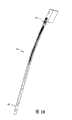
图1是第一实施例中遥测矫形植入物的透视图;Figure 1 is a perspective view of a telemetric orthopedic implant in a first embodiment;
图2是图1所示植入物的顶视图;Figure 2 is a top view of the implant shown in Figure 1;
图3是图1所示植入物的部分横截面侧视图;Figure 3 is a partial cross-sectional side view of the implant shown in Figure 1;
图4是图1所示植入物的详细透视图;Figure 4 is a detailed perspective view of the implant shown in Figure 1;
图5是第二实施例中遥测矫形植入物的透视图;Figure 5 is a perspective view of a telemetric orthopedic implant in a second embodiment;
图6是图5所示遥测矫形植入物的透视图;Figure 6 is a perspective view of the telemetric orthopedic implant shown in Figure 5;
图7是插入物的透视图;Figure 7 is a perspective view of the insert;
图8是第三实施例中遥测矫形植入物的透视图;Figure 8 is a perspective view of a telemetric orthopedic implant in a third embodiment;
图9是图8所示遥测矫形植入物的透视图;Figure 9 is a perspective view of the telemetric orthopedic implant shown in Figure 8;
图10是示出有限元分析结果的遥测矫形植入物的透视图;Figure 10 is a perspective view of a telemetric orthopedic implant showing finite element analysis results;
图11是示出数据输出vs.力的图表;Figure 11 is a graph showing data output vs. force;
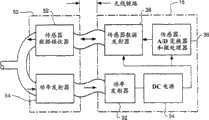
图12是示出电子组件和数据接收器的示意图;Figure 12 is a schematic diagram showing electronic components and data receivers;
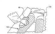
图13示出手持装置的使用;Figure 13 illustrates the use of a handheld device;
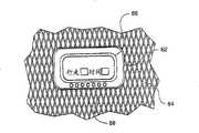
图14示出控制单元;Figure 14 shows the control unit;
图15是示出遥测矫形植入系统的示意图;Figure 15 is a schematic diagram illustrating a telemetric orthopedic implant system;
图16是示出骨折愈合曲线的图表;Figure 16 is a graph showing fracture healing curves;
图17是示出骨折未愈合曲线的图表;Figure 17 is a graph showing fracture nonunion curves;
图18示出人造骨折间隙;Figure 18 shows the artificial fracture gap;
图19示出在体外的生物力学试验设置;Figure 19 shows the biomechanical test setup in vitro;
图20是示出随负荷变化的应变vs.骨折间隙深度的图表;Figure 20 is a graph showing strain vs. fracture gap depth as a function of load;
图21是示出随间隙体积变化的应变vs.负荷的图表;Figure 21 is a graph showing strain vs. load as a function of gap volume;
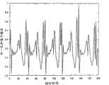
图22是示出加速计输出vs.时间的图表;Figure 22 is a graph showing accelerometer output vs. time;
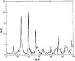
图23是示出幅度vs.频率的图表;Figure 23 is a graph showing amplitude vs. frequency;
图24是示出幅度vs.频率的图表;Figure 24 is a graph showing amplitude vs. frequency;
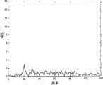
图25是示出幅度vs.频率的图表;Figure 25 is a graph showing amplitude vs. frequency;
图26是示出幅度vs.频率的图表;以及Figure 26 is a graph showing amplitude vs. frequency; and
图27是示出分析步态的步骤的流程图。Fig. 27 is a flow chart showing the steps of analyzing gait.
具体实施方式Detailed ways
“智能植入物”是能够感测其环境、应用智能确定是否需要采取措施并按照感测的信息采取行动从而以受控的有益方式来更改某些东西的植入物。智能植入物技术的一个有吸引力的应用是测量矫形植入物上的负荷。例如,髓内钉易受三种类型的负荷:弯曲、扭转和加压。这些负荷可通过测量安装到矫形植入物的一系列应变计的传感器输出而间接测量得出。在髓内钉的情况下,安装在钉外表面上在直径方面并列的应变计分别易受张力和压力。通常,植入物负荷弯曲时从传感器测量的应变比负荷加压时更高。A "smart implant" is one that senses its environment, applies intelligence to determine if action is required, and acts on the sensed information to change something in a controlled, beneficial way. An attractive application of smart implant technology is the measurement of loads on orthopedic implants. For example, intramedullary nails are subject to three types of loads: bending, torsion, and compression. These loads are measured indirectly by measuring the sensor output of a series of strain gauges mounted to the orthopedic implant. In the case of intramedullary nails, diametrically juxtaposed strain gauges mounted on the outer surface of the nail are susceptible to tension and compression, respectively. Typically, the strain measured from the sensor is higher when the implant is loaded under bending than when the load is compressed.
应变计的基本参数是其应变灵敏度,在量上表示为应变系数(G)。应变系数定义为电电阻微小变化与长度微小变化(应变)的比率,The fundamental parameter of a strain gauge is its strain sensitivity, expressed quantitatively as the gauge factor (G). The gauge factor is defined as the ratio of a small change in electrical resistance to a small change in length (strain),
其中R=额定电阻,ΔR=得到的电阻变化,而ε=应变。该电阻变化由两个重要因素引起:(a)材料电阻率变化;以及(b)材料变形时电阻器物理尺寸的变化。对于箔应变计,求得G为2.1。使用下式将电压记录转换成应变:where R = nominal resistance, ΔR = resulting change in resistance, and ε = strain. This change in resistance is caused by two important factors: (a) a change in material resistivity; and (b) a change in the physical dimensions of the resistor as the material deforms. For foil strain gauges, G is found to be 2.1. Convert the voltage recordings to strains using the following formula:
其中RL是引线电阻,Rg是应变计制造商规定的额定应变计电阻,GF是应变计制造商规定的应变系数,而Vr是由下式定义的电压比:whereRL is the lead resistance,Rg is the rated gage resistance specified by the gage manufacturer, GF is the gage factor specified by the gage manufacturer, andVr is the voltage ratio defined by:
其中VCH和VEX分别是所测量的信号电压和激励电压。whereVCH andVEX are the measured signal and excitation voltages, respectively.
使用胡克定律将应变与应力相关,该定律可重新设置为计算植入物(F)所受到的加压负荷和弯曲负荷,The strain is related to the stress using Hooke's law, which can be reformulated to calculate the compressive and bending loads experienced by the implant (F),
E.ε.A=F,......................................(4)E.ε.A=F, ...................................(4)
其中E是以吉帕斯卡(GPa)为单位的植入物刚度,ε=从仪器化植入物的输出所测量的应变,而A是以平方米(m2)为单位的植入物横截面积。通过从使用测力板或天平测量的肢体施加的总的向下力中减去植入物负荷,可得出骨头上的对应负荷。where E is the implant stiffness in gigapascals (GPa), ε = strain measured from the output of the instrumented implant, and A is the implant cross-section in square meters (m2 ) area. The corresponding load on the bone is derived by subtracting the implant load from the total downward force exerted by the limb as measured with a force plate or balance.
在如髓内钉等可植入医疗装置内包含传感器和其它电子组件,从无源负荷支撑装置到聪明的“智能”系统改变了其主要功能,它能够记录并监测患者的活动和遵守情况。The inclusion of sensors and other electronic components within implantable medical devices such as intramedullary nails has changed its primary function from passive load support devices to clever "smart" systems that record and monitor patient activity and compliance.
遥测髓内钉telemetry intramedullary nail
参照附图,图中类似的标号指示类似的要素,图1示出遥测髓内(IM)钉10。遥测IM钉10包括至少一个传感器12。图1中示出了一个特定的传感器配置。在此实施例中,传感器12位于IM钉10的近端区域20、中间或中轴区域22及远端区域24中。在图1所示实施例中,遥测IM钉10包括三个传感器12a、12b、12c,每个传感器对应一个区域。但是,本领域的技术人员将理解,可使用更多或更少数量的传感器,并且可以其它配置施加传感器。遥测钉10不断测量从传感器12生成的一组应变值。正如下面更详细所述的,遥测IM钉10将测量从该钉发射到阅读器装置以便计算分力而不干扰骨折愈合。Referring to the drawings, in which like numerals indicate like elements, FIG. 1 shows a telemetric intramedullary (IM)
遥测IM钉10可包括允许钉固定到骨头上的特征部件。例如,遥测IM钉10可包括近端孔26和/或远端孔28。在图1所示实施例中,遥测IM钉10包括两个近端孔26、一个远端孔28以及一个远端槽28,但本领域的技术人将理解,可以提供更多或更少数量的孔。The
在图5中可最清楚地看到,遥测IM钉10还包括一个或多个电子组件18,如印刷电路板。电子组件18与传感器12一起形成仪器电路。电子组件18可包括关联的信号调节电路、一个或多个微处理器、一个或多个存储装置、供电电源及通信组件。电子组件18允许在本地环境中就地测量变化。传感器12和电子组件18的组合为使用上述算法间接测量由于骨折变实而随时间变化的负荷提供了强有力的工具。这些间接测量又可用于向该环境中的临床医生提供信息,以供在进行临床决策时使用。As best seen in FIG. 5, the
为了保持遥测IM钉10的完整性,植入物设计必须保护这些组件,在传感器与其环境之间提供准确而稳定的连接,并保持植入物本身的功能性。在内部植入物结构内包含传感器引起了保持电子器件绝缘的“封装问题”,因为生物组织是极度敌对的环境。此外,不可低估普通消毒方法对电子组件18造成损害的风险。将IM钉10仪器化的设计考虑要求最小化对钉的机械和物理属性的任何损害,并允许大规模商业化和制造。某些设计可通过测量IM钉10仪器化前后的弯曲刚度与疲劳行为而得以确定。To maintain the integrity of the
在2-5中可最清楚地看到,IM钉10包括至少一个凹槽14。例如,凹槽14可为矩形、正方形、圆形、椭圆形或其某种组合。凹槽14可使用各种制造技术制成,包括但不限于机械加工、铣磨、磨削、锻造、铸造、冲压和注模。凹槽14深度为D,范围从0.1毫米到大约2.0毫米。凹槽的长度L可以在大约1毫米到大约100毫米的范围。在图3所示的实施例中,凹槽14为大约0.5毫米厚和大约5毫米长。凹槽14容纳传感器12和导线16。凹槽14保护传感器12和导线16,以免在手术插入过程期间磨损。凹槽14位于前表面或后表面上,使传感器12能够分别受到张力和压力。可使用多种高硬度粘合剂将传感器12固定在凹槽14中,包括环氧树脂、聚氨脂、UV可固化粘合剂以及医用级氰基丙烯酸酯。这些类型的固定方法对传感器12的性能不会造成不利影响。As seen most clearly in 2-5, the
另外,遥测IM钉10可包括在近端区域20中容纳电子组件18的凹槽14。凹槽14的尺寸加工为可容纳电子组件18。例如,电子组件可为大约56毫米长,大约6.2毫米宽和大约0.25毫米厚,并相应地确定凹槽14大小。凹槽14可与电子组件18的大小相同或稍微大些。In addition, the
备选地,应变计12和其它电子组件的安装可使用更含糊的方法执行,如电火花铣削加工植入物中的纵向剖面,在IM钉10中安装组件,并且激光焊接管各段。但是,使用此方案有几个缺点。焊接的局部热量往往使焊区周围的基体金属或应力失真和变形,这会影响植入物的耐腐蚀性。另外,激光束焊接使在熔融金属和直接邻近焊接点的基体金属之间有巨大的温差。在激光束焊接中加热和冷却速率比在弧焊中更高,并且受热影响区域更小。快速冷却速率会造成诸如高碳钢开裂的问题。Alternatively, mounting of the strain gauges 12 and other electronic components may be performed using more obscure methods such as EDM milling the longitudinal profile in the implant, mounting the components in the
有多种方式封装传感器12和其它电子组件。一些组件可能需要比其它组件更耐用的封装方法。例如,如果电池或其它可能危险的装置包括在电子系统中,则可能需要钛盒。备选地,如果这些组件在生物学上是良性的,则诸如聚氨酯或硅树脂等简单的灌封材料便证明是足够了。本领域的技术人员将理解,各种材料可用于灌封材料。重要的是,灌封材料充当隔离电子组件与周围环境的封盖。锡焊和焊接技术也可用于帮助在仪器化钉10内永久性密封传感器12和其它电子组件。将标准箔应变计替换为铂应变计也可增强耐用性和抗生物流体消毒和腐蚀。There are a variety of ways to package the
在图6的一个特定实施例中,传感器12和电子组件18覆盖有生物相容灌封材料30,如聚氨酯或硅树脂,以便提供气密封。由于传感器12和电子组件18气密封而与患者组织和流体隔开,因此,可实现遥测IM钉10的长期功能。同时,消除了非生物相容或有毒材料的泄露。灌封材料30是以液体或油灰样形式提供的电绝缘、防潮材料,并用作电气和电子设备敏感区上的保护涂层。灌封材料30可以是不透光或无色的。应变计12和导线16覆盖在灌封材料30中,灌封材料具有经受得住植入过程并恢复机械包封所需的适当机械特征。In a particular embodiment of FIG. 6, the
图7、图8和图9中示出了遥测仪器化钉10中电子组件18的备选布置。在此特定设计中,无源电子组件40位于近端区域20的凹槽14中,并且诸如供电电源、微处理器、数据存储装置和外部通信装置等有源电子组件42包含在单独的钉头插入物44中。在图9中可最清楚地看到,无源电子组件40可覆盖有灌封材料30以气密封电子组件40。在此配置中,遥测IM钉10以通常的方式植入,并且一旦IM钉已植入骨中,钉头插入物44便接附到遥测IM钉10。例如,钉头插入物44可穿入孔46中(图5中看到最清楚)。此特殊设计避免了任何敏感电子器件被植入过程损坏。无源与有源电子组件40、42之间的连接可使用电感耦合链路或经滑环的物理连接而形成。Alternative arrangements for the
遥测IM钉10可使用标准制造技术从生物相容材料构造。例如,该钉可由金属锻造,或者是手工或机制合成物,或从原料机器加工制成。备选地,遥测IM钉10可被铸造、注模或通过热均衡处理(HIP)压制。HIP制造工艺特别适用于生产具有设计为容纳传感器和电子组件的预成型凹槽的钉。The
在又一备选实施例中,遥测IM钉10可使用生物可降解合成物构造,其降解速率由感测的应变数据控制。此类装置比常规金属植入物更顺从,因为植入物的机械模量根据相邻骨头的愈合程度而变化。正在愈合的骨头上增大的负荷承载能力可触发活性剂的释放,这加速了钉的降解速率以便降低其负荷分担能力。另一方面,愈合慢的需要释放活性剂,这抑制了植入物材料的降解速率。活性剂的释放可使用微机电结构(MEMS)储集系统来控制,该系统在需要时释放化学操纵,这加速或减速钉的降解速率。仪器化组件可使用诸如可降解、多孔硅片等可恢复材料制成。否则,不可降解电子组件可能留在患者体内,这在某些情况下是可接受的。In yet another alternative embodiment, the
有限元建模以确定传感器的最佳位置Finite Element Modeling to Determine Optimal Location of Sensors
现在参照图10,传感器12可以为能够测量机械应变的装置,如箔或半导体应变计。备选地,传感器12可以为用于直接测量机械负荷的负荷传感器。图1中所示的实施例利用箔应变计测量应变。可通过有限元(FE)分析来确定传感器12的最佳位置以便测量应变。传感器12例如但不限于可定位在植入物10的工作区域。工作区域定义为两个固定孔26、28之间的区域。固定孔26、28适于容纳诸如螺钉等紧固件以将植入物10接附到骨头上。正如在图10中可看到的一样,较暗的阴影区表示应力集中。应力分布起因于通过患者的髋关节载入钉10的方式,并在与近端孔26对齐的钉10的外表面上产生高弯曲应力。一般情况下,在植入物内部与外部安装相反放置的传感器之间可观察到50%的应力下降。Referring now to FIG. 10, the
传感器sensor
遥测IM钉10包括传感器12。传感器12感测至少一个项目、事件、状况等。传感器12可以为许多类型,包括但不限于箔应变计、半导体应变计、振梁传感器、力传感器、压电元件、光纤布拉格光栅、陀螺罗经或巨磁阻抗(GMI)传感器。此外,传感器12可指示任何种类的状况,包括但不限于应变、pH、温度、压力、移位、流动、加速、方向、声发射、电压、脉冲、诸如特殊蛋白质指示等生物标志指示、诸如由氧气检测器、氧势检测器或二氧化碳检测器等检测的化学存在、代谢活动、或指示存在白细胞、红细胞、血小板、生长因子或胶原蛋白的生物指示。最后,传感器12可以为图像捕获装置。The
一些矫形应用可能需要不止一个传感器以测量不止一个项目、事件或状况。因此,一些植入物需要多信道能力。例如,遥测IM钉10可包括六个或更多个应变计。传感器12可以为传感器阵列或一系列分立传感器。遥测IM钉10也可设计有以玫瑰瓣状配置的多轴应变计,以使得能够在x、y和/或z平面中测量负荷。传感器12的配置也可设计成符合患者骨折的多种要求。传感器12设计成使得它不会损害植入物的性能。例如,传感器12必须是不显眼的、生物相容的,并且决不会影响植入物的已确定生物力学性能。已经显示出,在植入物与相邻骨头之间的紧配合在插入期间可能会严重变形。因此,所选传感器的分辨率最好大于8位(0.05%)。通过将轴负荷施加到仪器化钉上,可研究传感器的输出。Some orthopedic applications may require more than one sensor to measure more than one item, event or condition. Therefore, some implants require multi-channel capability. For example,
负荷配置设计为匹配一般在人股骨中观测到的负荷模式,即,经由近端紧固件通过钉发射的偏移垂直负荷。图11示出分别位于中轴区域(钉1)、远端区域(钉2)或近端区域(钉3)在内(压力)表面和外(张力)表面上具有两个应变传感器12的三个仪器化IM钉的应变vs.负荷曲线。在所有情况下,在钉上的负荷斜升到500N时,来自传感器对的响应都是完全线性的。另外,在施加负荷和从钉上去除负荷时观察到的迟滞很小或没有。The loading configuration was designed to match the loading pattern typically observed in the human femur, ie, offset vertical loads launched by the nails via the proximal fasteners. Figure 11 shows three
通信communication
电子组件18与数据接收器50通信。电子组件18从传感器12接收数据,并将数据发射到数据接收器50。电子组件18通过有线或无线连接来传输数据。这种传输可使用可用的技术,诸如ZIGBEETM、BLUETOOTHTM、The Technology Partnership Plc.(TTP)开发的Matrix技术或其它射频(RF)技术。ZIGBEE是设计用于无线个人区域网(WPAN)的高级通信协议的公布规格集合。ZIGBEE商标属于ZIGBEE联合公司(ZIGBEE Alliance Corp.,2400 Camino Ramon,Suite 375,SanRamon,California,U.S.A.94583)。蓝牙是实现无线装置之间近距离通信的技术工业标准。BLUETOOTH商标属于蓝牙SIG公司(BluetoothSig,Inc.,500 108th Avenue NE,Suite 250,Bellevue Washington,U.S.A.98004)。RF是使用电磁波发射和接收数据的无线通信技术,使用的信号频率在大约0.1MHz以上。由于尺寸和功耗的限制,遥测IM钉10可利用医用可移植通信服务(MICS)以便满足某些国际通信标准。
仪器化系统Instrumentation system
图12示出诸如印刷电路板的电子组件18和数据接收器50。电子组件18提供功率发射器32、DC电源34、组合模/数变换器和微处理器36以及传感器数据发射器38。数据接收器50包括传感器数据接收器52和功率发射器54。本领域的技术人员将理解,发射器和接收器虽然示为单独的组件,但它们可组合在单个单元中,有时称为收发器。在图12所示实施例中,功耗和数据传输是无接触式的。电子组件18可包括如下任何项:(1)任意数量的箔应变计;(2)匹配数量的低噪声、低功率仪器化放大器;(3)匹配数量的惠斯登电桥电阻器网络;(4)匹配数量的应变计零调整;以及(5)具有噪声滤波功能的板上电源。FIG. 12 shows an
功率管理power management
遥测IM钉10可包含一个或多个功率管理策略。功率管理策略可包括植入的电源或感应电源。植入的电源可以为简单的电源,如电池,或者更复杂的电源,如能量回收装置。能量回收装置可包括运动驱动的压电或电磁发电机以及关联的电荷存储装置。感应电源包括感应耦合系统和射频(RF)电磁场。
最后,遥测IM钉10可包含存储装置(未示出)。存储装置可通过感应/RF耦合或内部能量回收装置充电。存储装置必须具有充足的容量以存储至少足以执行单步测量和随后处理并传递结果的能量。Finally, the
图13示出手持装置60放在患者100的大腿102上。手持装置60生成激励电子组件18的RF波。被激励的电子组件18检索存储的传感器读数,并经由载波将它们发送到手持装置60。手持装置60可配有处理器(未示出)以便直接分析传感器读数,或者手持装置60可连接到计算机以便分析传感器读数。FIG. 13 shows the
通信communication
对可植入遥测系统的要求是严格的,并且必须利用强健的方法从矫形植入物捕获数据。本领域的以前尝试未曾提供在仪器化髓内钉所需范围内的信号。因此,遥测IM钉10其最简单的形式具有有线接口。换而言之,电子组件18经导线(未示出)连接到外部控制单元62。控制单元62可作为可佩戴装置放在患者100身上,如臂带、腕带、大腿带或脚链带。备选地,控制单元62可连接到铸件64,诸如通过将控制单元放在铸件内,或者将控制单元接附到铸件外部。The requirements for implantable telemetry systems are stringent and must utilize robust methods to capture data from orthopedic implants. Previous attempts in the art have not provided a signal in the range required for instrumented intramedullary nails. Thus, the
控制单元62可包括显示器66和/或扬声器68。显示器66可用于显示传感器读数,提供警告灯、倒计时器,以允许患者预料重要事件,如铸件去除,或打发时间的娱乐装置,如电子游戏。扬声器68可用于提供声音,诸如预先记录的指令、警告声音或游戏声音。
患者有效地佩戴不断监测患者活动的控制单元62。如果发生重大事件,如外伤事件或失去基本身体功能,控制单元62感测到此变化,就发出可听到和/或看到的警报。备选地或者除警报外,控制单元62还可发送信息到另一装置,该装置可提示佩戴者提供信息以确认患者的状态。控制单元62也可用于通知紧急援助组即将发生的危险和其它有关信息,如患者的位置。在此最后的示例中,控制单元62可包括定位控制单元和患者的全球定位系统(GPS)模块。The patient effectively wears a
控制单元62可装在实际上任何类型的材料中,如塑料、橡胶、金属、玻璃、陶瓷、木材、石料、长纤维复合材料、短纤维复合材料、非纤维复合材料等。显示器66可以是液晶显示器、发光二极管显示器、等离子显示器、数字光处理、硅基液晶显示器、阴极射线管等。The
但是,在其它实施例中,遥测IM钉10具有无线通信设施以允许患者在周围自由移动。图12显示了部分此实施例。However, in other embodiments, the
遥测IM钉10不但包括传感器,而且可包括作用单元,以基于传感器读数或外部命令来执行某些功能。图15示出遥测植入系统110。遥测植入系统110包括遥测矫形植入物112、控制单元114、阅读器116及计算装置118。阅读器116以无线方式与控制单元114通信以发射和接收数据。阅读器116通过有线或无线方式连接到计算装置118。计算装置118可以为多种已知装置,如个人数字助理、台式计算机、膝上型计算机、笔记本PC、生物统计监测装置、手持计算机或服务器。计算装置118用于分析从矫形植入物112接收的数据。计算装置118可用于存储数据和/或对遥测矫形植入物112进行编程。阅读器116和计算装置18可合并到单个装置中。The
矫形植入物112包括一个或多个传感器120、微控制器122、一个或多个存储的可输送项124以及一个或多个作用单元126。传感器120将诱导信号输出到前置放大器(未示出),然后到放大器(未示出),然后再到滤波器(未示出)。信号随后传播到微控制器122,微控制器经算法处理传感器信号,并决定信息是要存储还是要发送到作用单元126。可从制造商那或根据外科医生的偏好预先编程用于决定如何作用的算法。作用单元126可通过有线或无线方式与微控制器122通信。在从控制单元114或微控制器122收到信号后,作用单元126部署存储的可输送项124,这包括但不限于生物操纵、抗生素、抗发炎药、止痛药、生骨因子、无线电标志、血管生成因子、血管扩张因子和/或生长因子。The
作用单元126可以为MEMS装置,如输送特定量药剂或其它存储的可输送项124的泵。矫形植入物112可包括全都包含相同存储可输送项124的这些泵中的几个泵,以便在一个或多个泵故障的情况下提供冗余。泵包含要输送的存储可输送项124的储集器。使用任何类型的微流控机构来输送存储的可输送项124,如旋转泵、活塞泵、形状记忆材料泵等。The
控制单元114包括发电机128、能量存储装置130、逻辑电路132、微控制器134、RF检测器线圈136以及RF负荷开关138。
用户接口user interface
在一些实施例中,计算装置118包括图形用户接口(GUI)。GUI允许保健提供者和/或患者基于在本地或远程(例如电视医疗)从遥测矫形植入物112收集的数据而显示信息。GUI识别要与其通信的系统,提示用户进行安全清理,验证安全清理,并从遥测矫形植入物112或阅读器116下载数据。数据随后可进一步被处理成各种形式,从简单的离散愈合进展状态数字或措辞到复杂的信息,诸如患者步行周期曲线的图形再现、患者活动、患者服从性、患者数据、保健提供者信息、植入物制造信息、外科手术技术、x光照片信息、计算机断层扫描信息、磁共振成像信息。In some embodiments,
此外,GUI可由于感测到的信息而警告患者。逻辑电路132可用于监测从遥测矫形植入物112收到的数据,并在某些变量超过预先配置的极限时发送信号。警报可以让用户知道何时需要医生介入进行临床就诊,何时装置已超负荷,或者如何在无外科医生介入情况下管理已发生的情况。Additionally, the GUI can alert the patient due to the sensed information.
遥测植入系统110有许多用途。例如,患者可经外科手术介入来修复持续的创伤或关节重建,在这段时间内,患者接受遥测矫形植入物以帮助创伤修复。植入物可利用设计为通过一个或多个传感器监测患者恢复各方面的机电系统,决定是否需要采取措施,并因此根据编程采取行动。
骨头愈合的早期监测Early Monitoring of Bone Healing
虽然用夹板固定和外科手术可有助于骨头愈合,但骨折的愈合仍需要充分的生理愈合,这可通过使用传感器和生物遥测系统,不断地监测植入物与周围骨头之间的原地负荷分布变化来实现。已知骨头的质量和结构受对它们施加的机械负荷的影响。由于内部矫形固定系统管理差造成的应力屏蔽而缺少适当的负荷时,骨头质量会降低,导致骨折愈合受损。遥测矫形植入物的主要功能是在外科手术放置后立即承载负荷。例如,遥测矫形钉在外科手术放置在髓内管道后立即承载负荷。随着骨折愈合的进展,植入物与骨头之间的负荷分担改变了。这可使用根据骨折位置在矫形植入物内最佳定位的应变计来跟踪。传感器用于通过不断地监测正在愈合的骨头在所有空间分量中的负荷分量,来监测骨折情况下愈合的进展,这是从X射线中无法获得的。定期跟踪将提供显示愈合前各部分相对运动逐渐减少的图表。While splinting and surgery can aid bone healing, fracture healing still requires adequate physiologic healing, which can be achieved through the use of sensors and biotelemetry systems that continuously monitor the in situ load between the implant and the surrounding bone distribution changes. It is known that the mass and structure of bones is affected by the mechanical loads applied to them. In the absence of proper loading due to stress shielding due to poor management of the internal orthopedic fixation system, bone quality is reduced, resulting in impaired fracture healing. The primary function of telemetric orthopedic implants is to carry loads immediately after surgical placement. For example, telemetric orthopedic nails are loaded immediately after surgical placement in the intramedullary canal. As fracture healing progresses, the load sharing between the implant and the bone changes. This can be tracked using strain gauges positioned optimally within the orthopedic implant according to fracture location. Sensors are used to monitor the progress of healing in fracture situations by constantly monitoring the loading components of the healing bone in all spatial components, which cannot be obtained from X-rays. Regular follow-up will provide a graph showing the gradual decrease in relative motion of the parts before healing.
每个骨折患者生成其自己独一无二的愈合曲线;但是,愈合曲线的一般形状指示骨折将发展为愈合状况还是不愈合状况。从患者生成的愈合曲线取决于多种因素,包括骨折的类型和位置、健康状况(潜在的疾病)、年龄、活动、康复以及达到负重的时间。Each fracture patient generates its own unique healing curve; however, the general shape of the healing curve indicates whether the fracture will develop into a unioned or nonunion condition. The healing curve generated from the patient depends on a variety of factors, including the type and location of the fracture, health status (underlying disease), age, activity, rehabilitation, and time to weight bearing.
图16和图17以示意图方式示出显示仪器化IM钉与周围骨头之间负荷分布的假设负荷vs.愈合时间曲线。在图16中,骨折发展为愈合状况,而在图17中,骨折保持不愈合状况。虽然骨折愈合导致植入物负荷降低,但钉的其余负荷可能很大,并且预计随着患者活动而增大。已经间接表明,在植入物去除后骨头的负荷可增大高达50%。在相邻骨头测量的负荷可通过从通过肢体施加的负荷减去植入物负荷来确定,而通过肢体施加的负荷可使用测力板或天平来确定。临床医生也可测量通过对侧肢体作用的负荷,以便提供完全有功能肢体的参考测量。Figures 16 and 17 schematically show hypothetical load vs. healing time curves showing the load distribution between the instrumented IM nail and the surrounding bone. In Figure 16, the fracture developed into a unioned condition, while in Figure 17, the fracture remained in a nonunion condition. Although fracture healing results in reduced implant loading, the remaining loading of the nail can be substantial and is expected to increase with patient activity. It has been indirectly shown that the load on the bone can be increased by up to 50% after implant removal. The load measured at the adjacent bone can be determined by subtracting the implant load from the load applied through the limb, which can be determined using a force plate or balance. The clinician may also measure the load acting through the contralateral limb to provide a reference measure of a fully functioning limb.
可以几种不同的方式使用愈合曲线。首先,在遥测矫形植入物有效的情况下,植入物或控制单元不断地记录数据。在例如髓内钉的情况下,记录在患者走动时植入物上的应变。外科医生或其它保健提供者可在临床设置中从植入物或控制单元下载数据。数据被处理,并且愈合曲线从该数据中生成。如果外科医生观察到植入物上的应变随时间而降低,类似于图16的图表,则这表示周围的硬组织正在接受一些负荷,并且因此骨折在愈合。但是,如果植入物上的应变未随时间而变化,并且处于与患者离开医院或其它保健机构时近似的程度,类似于图17的图表,则这表示周围的硬组织未承载负荷,因此,骨折并未在愈合。Healing curves can be used in several different ways. First, where telemetric orthopedic implants are effective, the implant or control unit continuously records data. In the case of eg intramedullary nails, the strain on the implant is recorded while the patient is ambulatory. A surgeon or other healthcare provider can download data from the implant or control unit in a clinical setting. Data is processed and a healing curve is generated from this data. If the surgeon observes a decrease in strain on the implant over time, similar to the graph of Figure 16, this indicates that the surrounding hard tissue is receiving some loading, and thus the fracture is healing. However, if the strain on the implant does not change over time and is at a level similar to when the patient leaves the hospital or other healthcare facility, similar to the graph of Figure 17, then this indicates that the surrounding hard tissue is not carrying the load, and therefore, The fracture is not healing.
第二,遥测矫形植入物可以为无源装置,它不会不断地记录数据,而是只在暴露于能量源时才记录。在此实施例中,医院或保健机构提供能量源,其激励遥测矫形植入物并允许它记录数据。在此示例中,使遥测矫形植入物通电,用植入物在受影响的骨头上施加所设置级别的负荷,并捕获传感器读数。例如,植入物可以为髓内钉,并且在施加负荷时传感器可测量钉上的应变。感测的数据被下载和处理。在此示例中,感测的数据必须与以前的测量进行比较。例如,可在预定的时段进行测量,例如,每天或每周。如果施加到骨头上的负荷未改变,而应变与以前的测量相比已随时间降低,则这表示硬组织在分担一些负荷,因此,骨折正在愈合。但是,如果植入物上的应变与以前的测量相比未随时间而变化,则这表示周围的硬组织未承载任何负荷,因此,骨折并未在愈合。Second, telemetric orthopedic implants can be passive devices that do not continuously record data, but only when exposed to an energy source. In this embodiment, a hospital or healthcare facility provides an energy source that energizes a telemetric orthopedic implant and allows it to record data. In this example, a telemetry orthopedic implant is energized, a set level of load is applied with the implant to the affected bone, and sensor readings are captured. For example, the implant could be an intramedullary nail, and the sensor could measure the strain on the nail when a load is applied. The sensed data is downloaded and processed. In this example, the sensed data must be compared with previous measurements. For example, measurements may be taken at predetermined time periods, eg, daily or weekly. If the load applied to the bone has not changed, but the strain has decreased over time compared to previous measurements, this indicates that the hard tissues are sharing some of the load and, therefore, the fracture is healing. However, if the strain on the implant has not changed over time compared to previous measurements, this indicates that the surrounding hard tissue is not carrying any load and, therefore, the fracture is not healing.
本文所述的这种遥测矫形植入物利用这样一种算法,该算法基于初始负荷测量中的变化率,提供骨折是否会愈合的及早指示。传感器提供的信息也可用于设计在强度和刚度方面与周围骨头更适应的新型矫形植入物。The telemetric orthopedic implant described herein utilizes an algorithm that provides an early indication of whether a fracture will heal based on the rate of change in initial load measurements. The information provided by the sensors could also be used to design new orthopedic implants that better adapt to the surrounding bone in terms of strength and stiffness.
可使用塑料骨折模型在生物体外演示遥测矫形植入物的功能。在图18和图19所示的这种试验中,在完整的股骨模型200中植入遥测髓内钉220,并且在观察应变随负荷而变的变化时逐渐引入周围的骨折间隙210。因此,一般在体内观察到骨折状况倒退。应变计施加到钉220的内侧和外侧,定位在钉的轴上以与骨折间隙位置相对应。根据此研究获得的数据解释表示测量体内骨头愈合的能力。钉结构的加载以逐步置换方式按预定增量从0lbf加到300lbf,并且在每次负荷递增时测量应变。在骨头模型完全完整时,进行第一系列的应变测量。在出现75%的骨头间隙210时,进行下一系列的应变测量。随后,分别在出现50%、25%和0%的骨头间隙210时,进行第三、第四和第五系列的应变测量。在骨折间隙分段重新插入其原始位置时,进行最后一系列的应变测量。骨头间隙210大约为5毫米厚,位于骨头模型的轴上,因此它将在钉200工作距离一半的位置,这表示其是闭锁紧固件之间距离的一半。The functionality of telemetric orthopedic implants can be demonstrated in vitro using a plastic fracture model. In this test shown in Figures 18 and 19, a telemetric
图20示出使用人为引起的周围间隙的反向模拟的骨头愈合。图21示出了出现100%(完全完整)、75%、50%、25%以及0%(完全断裂)时从塑料骨折模型获得的负荷vs.应变曲线。Figure 20 shows bone healing using an inverse simulation of an artificially induced surrounding gap. Figure 21 shows the load vs. strain curves obtained from the plastic fracture model at 100% (complete integrity), 75%, 50%, 25% and 0% (complete fracture).
步态分析Gait Analysis
本发明还包括步态分析工具,它收集、处理和存储步态数据,直至外部装置访问该数据并将它呈现给查看者,如患者、外科医生、保健提供者或物理治疗师。遥测矫形植入物可包括加速计,加速计可以大约从1到大约2000Hz范围的采样率输出随时间的加速度变化。参照图22,例如以图形方式示出由佩戴加速计的佩戴者进行正常无人帮助的步态训练时得出的数据输出。随后可根据需要处理传感器输出数据以进行分析。一个这种方法是将数据从时域转换到频域,并寻找生物统计标志或模式。图23-25显示转换到频域的类似于图22中数据的数据。在这些图中,在各种频率可看到明显的峰值,它们定义了在图23-25中视为差异的佩戴者的步态特征。患者的步态随时间和老化而逐渐变化,或者在患者下肢的任何骨头受到严重跌打损伤时突然发生变化。在图26中显示了人为引起的防痛步态模式的频域步态特征。The present invention also includes a gait analysis tool that collects, processes, and stores gait data until an external device accesses the data and presents it to a viewer, such as a patient, surgeon, healthcare provider, or physical therapist. The telemetric orthopedic implant may include an accelerometer that may output acceleration over time at a sampling rate ranging from about 1 to about 2000 Hz. Referring to Fig. 22, for example, the output of data resulting from normal unassisted gait training by a wearer wearing an accelerometer is shown graphically. The sensor output data can then be processed for analysis as required. One such approach is to transform the data from the time domain to the frequency domain and look for biometric signs or patterns. Figures 23-25 show data similar to the data in Figure 22 transformed into the frequency domain. In these figures, distinct peaks are seen at various frequencies, which define the wearer's gait characteristics which are considered differences in Figures 23-25. A patient's gait changes gradually with time and aging, or suddenly when any bone in the patient's lower extremity is severely traumatized. The frequency-domain gait signatures of the artificially induced anti-pain gait pattern are shown in Fig. 26.
步态分析工具允许收集和处理基本信息,产生相对于对象的步行周期的决定性宝贵数据。此数据可用于诊断至少患者下肢中的愈合状态,下肢在受伤时会妨碍正常的步行周期。外科医生过去不得不依赖放射照相术或其它成像技术来确定患者骨头愈合阶段的一连串过程。这些工具有所帮助,但允许在诊断中有误差。有几个方面会出现这种机会,包括但不限于图像质量、视差和误诊。此外,即使这些诊断工具存在,但外科医生也更信赖患者鉴定书而不是图像。步态分析工具通过为外科医生提供整个愈合过程中从患者收集的客观公正的数据,消除了诊断中的猜测成分。步态分析工具使外科医生在愈合过程的早期就理解是否需要介入以使用诸如可注入粘合剂或脱钙骨基质等生物材料来增进治疗而加速愈合,或者是否可能必需进行修正手术。由于本文所述的遥测矫形植入物具有存储功能,因此患者数据可存储,从而可方便地传输数据。此数据可包括个人数据、患者历史信息以及患者活动情况。如果捕获到活动,外科医生就可了解患者是否一直准确地执行了术后康复制度。这使外科医生可准确地预测并规定进一步的制度,而这对于目前采用的技术是不可行的。Gait analysis tools allow the collection and processing of essential information, yielding decisive and valuable data relative to the subject's gait cycle. This data can be used to diagnose the state of healing in at least a patient's lower extremity, which when injured prevents the normal gait cycle. Surgeons used to have to rely on radiography or other imaging techniques to determine the cascade of stages in a patient's bone healing. These tools help, but allow for error in diagnosis. There are several areas where this opportunity arises, including but not limited to image quality, parallax, and misdiagnosis. Furthermore, even when these diagnostic tools exist, surgeons rely more on patient testimonials than images. Gait analysis tools take the guesswork out of diagnosis by providing the surgeon with unbiased data collected from the patient throughout the healing process. Gait analysis tools allow surgeons to understand early in the healing process whether intervention is required to enhance healing with biomaterials such as injectable adhesives or demineralized bone matrix to speed healing, or whether revision surgery may be necessary. Due to the storage capabilities of the telemetric orthopedic implants described herein, patient data can be stored so that data can be easily transferred. This data can include personal data, patient history information, and patient activity. If movement is captured, the surgeon can see if the patient has been following the post-operative rehabilitation regime accurately. This allows the surgeon to accurately predict and prescribe further regimes that are not feasible with currently employed techniques.
图27示出实现步态分析的步骤。在步骤310,诸如医生或保健提供者等人开始操作。在步骤312,该人从患者那读取数据。例如,患者可具有在患者走动时不断测量数据的有源遥测矫形植入物。在例如髓内钉的情况下,在患者走动时记录植入物的加速度。外科医生或其它保健提供者可在临床设置中从植入物或控制单元下载数据。数据下载后,在步骤314进行处理,以便将数据从时域转换到频域。这使医生、保健提供者或软件可寻找生物统计标志或模式。Figure 27 shows the steps to implement gait analysis. At
由于不断地监测数据,因此在步骤312还下载了额外的数据。例如,在患者坐着时可能也记录了数据。在可选步骤316中,一个判决用于寻找全局下载数据内的复步峰值和单步峰值数据。通过利用判决316,可确保在全局数据中存在步态信息。如果步态信息不存在,则医生或保健提供者在另一时间返回步骤312以检索全局数据。Additional data is downloaded at
在步骤318到332,提取步态信息并分组放置以便分析。这样,可确保医生或保健提供者看到步态如何从一组变到下一组。例如,第一组步态信息可源自第一时段,而第二组步态信息可源自第二时段。In
在步骤318,估计复步幅度、单步幅度、复步频率和单步频率。在步骤320,生成简化的单个步行周期组。在步骤322,全局数据被拆散并与简化的单个步行周期组相关。在步骤324,迭代地处理数据。在步骤326,判定该相关是否在自适应阈值以上。如果是,则在步骤330,将相关的周期确定为一个步态组。如果不是,则在步骤328,将该周期确定为非步态数据。在步骤332,迭代地处理数据,直至所有数据被分析为步态数据或非步态数据。一旦确定了步行周期,就在步骤334分析步行周期,并在步骤336结束该过程。In
备选地,可在医院或保健机构收集和分析步态数据。换而言之,在有医生或保健提供者时患者走动,并记录数据。但是,这种类型的数据收集不允许长时期分析。另外,这种类型的数据收集不允许测量患者的服从性,因为患者更可能在医院或保健机构外时不服从,而在有医生或保健提供者时服从。但是,在离散时段得到的步态数据仍提供了骨折是否正在向愈合状况发展的指示。Alternatively, gait data may be collected and analyzed in a hospital or healthcare facility. In other words, the patient walks around while the doctor or healthcare provider is present, and the data is recorded. However, this type of data collection does not allow for long-term analysis. Additionally, this type of data collection does not allow for measurement of patient compliance since patients are more likely to be noncompliant outside of a hospital or healthcare facility than to be compliant when a physician or healthcare provider is present. However, gait data obtained at discrete time intervals still provides an indication of whether the fracture is progressing towards a healing state.
结论in conclusion
虽然所述实施例集中在专门设计用于骨头愈合的仪器化髓内钉的功能,但备选实施例包括在其它可植入外伤产品诸如板、接骨螺钉、插入套管螺钉、针、棒、U形钉和线缆内包含传感器和其它电子组件。此外,本文所述的仪器化可扩展到关节置换植入物,诸如全膝关节置换(TKR)和全髋关节置换(THR)、牙植入物以及颅骨上颌面植入物。While the described embodiments focus on the functionality of instrumented intramedullary nails specifically designed for bone healing, alternative embodiments include functions in other implantable trauma products such as plates, bone screws, inserting cannulated screws, needles, rods, The staples and cables contain sensors and other electronic components. Furthermore, the instrumentation described herein can be extended to joint replacement implants, such as total knee replacements (TKR) and total hip replacements (THR), dental implants, and craniomaxillofacial implants.
患者接收无线仪器化关节重建产品。植入物内的机电系统可用于使用一个或多个传感器监测患者恢复情况,并且决定在患者康复过程中是否需要任何介入。遥测关节置换不断地测量在植入物内生成的一整组应变值,并将它们从患者那发射到实验室计算机系统,而不干扰植入物的主要功能。备选地,可利用在患者体外可佩戴装置形式的有线系统。再者,机电系统可设计为监测患者恢复的各个方面。A patient receives a wireless instrumented joint reconstruction product. The electromechanical system within the implant can be used to monitor the patient's recovery using one or more sensors and decide if any intervention is required during the patient's recovery. Telemetric arthroplasty continuously measures the full set of strain values generated within the implant and transmits them from the patient to the laboratory computer system without interfering with the primary function of the implant. Alternatively, a wired system in the form of a device wearable outside the patient's body may be utilized. Furthermore, electromechanical systems can be designed to monitor various aspects of patient recovery.
无线技术可引入牙植入物中,以使得能够及早检测到植入物超负荷。长时间过多的咬合力施加到植入物上,超过了骨植入物界面承受和适应这些力的能力,会发生超负荷,从而导致植入物界面出现称为“骨分裂”的纤维性置换,并最终导致植入物失效。再者,通信链路可用于从外部源有选择地存取存储器中的应变数据。Wireless technology can be introduced in dental implants to enable early detection of implant overload. Overloading occurs when excessive occlusal forces are applied to the implant over a prolonged period of time, exceeding the ability of the bone-implant interface to withstand and accommodate these forces, resulting in a fibrous condition at the implant interface known as "bone splitting" Replacement, and eventually lead to implant failure. Furthermore, a communication link may be used to selectively access the strain data in the memory from an external source.
与仪器化过程关联的技术也可适用于监测软组织修复(例如,皮肤肌肉、筋、韧带、软骨等)和内脏器官(肾、肝、胃、肺、心等)的修复与监测。Techniques associated with instrumented procedures can also be adapted to monitor soft tissue repair (eg, skin muscle, tendons, ligaments, cartilage, etc.) and visceral organ (kidney, liver, stomach, lung, heart, etc.) repair and monitoring.
本发明与现有技术相比的优点涉及在固定装置内包含一些组件,包含方式为保护这些组件,在传感器与其环境之间提供准确而可靠连接,保持植入物本身的功能性,并适合大规模制造。该装置允许收集和处理信息,得出相对于患者骨头愈合一连串过程有用的临床数据。The advantages of the present invention over the prior art relate to the inclusion of components within the fixture in such a way as to protect them, provide an accurate and reliable connection between the sensor and its environment, maintain the functionality of the implant itself, and be suitable for large Manufacturing at scale. The device allows information to be collected and processed to derive useful clinical data with respect to the patient's chain of bone healing.
仪器化装置通过提供在整个愈合过程从患者那收集的患者的客观定量数据,消除了在诸如x射线、CT和MRI成像等常规诊断技术中的猜测成分。目前,没有装置能量化在骨折愈合期间以及在不同患者和理疗活动期间受到的骨骼负荷。此外,在骨折愈合期间植入物与相邻骨头之间的负荷分布也是未知的。此类数据将有助于优化术后治疗计划,以改进骨折愈合。本文所述的装置通过使用板上传感器和允许存储患者数据的存储器设施,从而允许及早传输数据,解决了此问题。此数据包括患者历史情况和患者活动情况。装置还使得能够在需要时外科医生及早介入,诸如给药、注射矫正生物制剂、粘合剂或脱钙骨基质,以帮助促进/加速骨头愈合或修正手术。The instrumented device removes the element of guesswork in conventional diagnostic techniques such as x-ray, CT and MRI imaging by providing objective quantitative data collected from the patient throughout the healing process. Currently, there are no devices to quantify the bone loads experienced during fracture healing and during different patient and physiotherapy activities. Furthermore, the load distribution between the implant and the adjacent bone during fracture healing is also unknown. Such data will help optimize postoperative treatment planning to improve fracture healing. The devices described herein solve this problem by using on-board sensors and a memory facility that allows patient data to be stored, thereby allowing data to be transmitted early. This data includes patient history and patient activity. The device also enables early intervention by the surgeon when needed, such as drug delivery, injection of corrective biologics, adhesives or demineralized bone matrix, to help promote/accelerate bone healing or revision surgery.
鉴于以上所述,将看到实现和获得本发明的几个优点。其中,潜在的临床好处包括:减少临床就诊次数,减轻患者遭受的痛苦,改进有关骨折愈合的数据和及早通知延迟情况或不愈合情况。In view of the foregoing, it will appear that several advantages of the invention are realized and attained. Among the potential clinical benefits are: fewer clinical visits, less suffering for patients, improved data on fracture healing and early notification of delays or non-unions.
实施例选择和描述成最好地解释本发明的原理及其可行的应用,由此使本领域的技术人员能够在各种实施例中最好地利用本发明,并进行适当考虑到的特定使用的各种修改。The embodiments were chosen and described to best explain the principles of the invention and its possible applications, thereby enabling others skilled in the art to best utilize the invention in its various embodiments, with due regard to particular uses various modifications.
在不脱离本发明范围的情况下,可对本文所述和所示结构和方法进行各种修改,因此,上述说明书中所包含或附图中所示的所有内容应理解为说明性而不是限制性的。因此,本发明的广度和范围不应受任何上述示范实施例的限制,而是仅应根据随附权利要求书及其等同方案来定义。As various changes could be made in the structures and methods described and illustrated herein without departing from the scope of the invention, all matter contained in the above description or shown in the accompanying drawings shall be interpreted as illustrative and not in a limiting sense. sexual. Thus, the breadth and scope of the present invention should not be limited by any of the above-described exemplary embodiments, but should be defined only in accordance with the appended claims and their equivalents.
Claims (19)
Translated fromChineseApplications Claiming Priority (4)
| Application Number | Priority Date | Filing Date | Title |
|---|---|---|---|
| US71055005P | 2005-08-23 | 2005-08-23 | |
| US60/710,550 | 2005-08-23 | ||
| US60/728,374 | 2005-10-19 | ||
| US60/816,675 | 2006-06-27 |
Related Child Applications (1)
| Application Number | Title | Priority Date | Filing Date |
|---|---|---|---|
| CN201310689606.6ADivisionCN103637840A (en) | 2005-08-23 | 2006-08-23 | Telemetric orthopaedic implant |
Publications (1)
| Publication Number | Publication Date |
|---|---|
| CN101291634Atrue CN101291634A (en) | 2008-10-22 |
Family
ID=40035584
Family Applications (1)
| Application Number | Title | Priority Date | Filing Date |
|---|---|---|---|
| CNA2006800385741APendingCN101291634A (en) | 2005-08-23 | 2006-08-23 | Telemetric Orthopedic Implants |
Country Status (1)
| Country | Link |
|---|---|
| CN (1) | CN101291634A (en) |
Cited By (19)
| Publication number | Priority date | Publication date | Assignee | Title |
|---|---|---|---|---|
| CN103687559A (en)* | 2011-05-17 | 2014-03-26 | 史密夫和内修有限公司 | Telescoping IM nail and actuating mechanism |
| CN103796618A (en)* | 2011-07-15 | 2014-05-14 | 史密夫和内修有限公司 | Fiber-reinforced composite orthopedic device with embedded electronics |
| CN104023671A (en)* | 2011-12-15 | 2014-09-03 | 欧特克公司 | Implanted devices and related user interfaces |
| CN106687061A (en)* | 2014-09-08 | 2017-05-17 | 皇家飞利浦有限公司 | Optical shape sensing for soft tissue balancing in orthopedics |
| CN108186101A (en)* | 2012-02-03 | 2018-06-22 | 捷迈有限公司 | For the bone plate of elastic bone joining |
| CN110249389A (en)* | 2016-08-26 | 2019-09-17 | 塞奎阿纳医疗股份公司 | System and method for managing and analyzing the data generated by implantable devices |
| CN111182860A (en)* | 2017-11-30 | 2020-05-19 | 布鲁恩生物有限责任公司 | Implant Evaluation Using Acoustic Emissions |
| US10716605B2 (en) | 2010-06-23 | 2020-07-21 | Zimmer, Inc. | Flexible plate fixation of bone fractures |
| CN111658107A (en)* | 2014-10-23 | 2020-09-15 | 诺威适骨科专科公司 | System for bone growth |
| CN112055574A (en)* | 2018-04-04 | 2020-12-08 | Gc美学制造有限公司 | Implants |
| CN112867459A (en)* | 2018-10-15 | 2021-05-28 | 马佐尔机器人有限公司 | Force prediction for spinal implant optimization |
| US11324538B2 (en) | 2019-12-04 | 2022-05-10 | Biomet Manufacturing, Llc | Active bone plate |
| US11406433B2 (en) | 2010-06-23 | 2022-08-09 | Zimmer, Inc. | Flexible plate fixation of bone fractures |
| CN115414162A (en)* | 2022-11-04 | 2022-12-02 | 清华大学 | Orthopedic intervertebral fusion cage, strain monitoring system and method caused by vertebral body fusion |
| CN115414105A (en)* | 2022-11-04 | 2022-12-02 | 清华大学 | Orthopedic intramedullary nail, force and strain monitoring system and method of human fracture end |
| WO2023124548A1 (en)* | 2021-12-27 | 2023-07-06 | 清华大学 | Cfr-peek orthopedic implant and preparation method therefor, and wireless sensing device |
| US11793916B2 (en) | 2012-02-15 | 2023-10-24 | Sequana Medical Nv | Systems and methods for fluid management |
| US11839712B2 (en) | 2004-08-18 | 2023-12-12 | Sequana Medical Nv | Implantable fluid management system for treating heart failure |
| US11844890B2 (en) | 2017-05-24 | 2023-12-19 | Sequana Medical Nv | Formulations and methods for direct sodium removal in patients having heart failure and/or severe renal dysfunction |
- 2006
- 2006-08-23CNCNA2006800385741Apatent/CN101291634A/enactivePending
Cited By (23)
| Publication number | Priority date | Publication date | Assignee | Title |
|---|---|---|---|---|
| US11839712B2 (en) | 2004-08-18 | 2023-12-12 | Sequana Medical Nv | Implantable fluid management system for treating heart failure |
| US10716605B2 (en) | 2010-06-23 | 2020-07-21 | Zimmer, Inc. | Flexible plate fixation of bone fractures |
| US11406433B2 (en) | 2010-06-23 | 2022-08-09 | Zimmer, Inc. | Flexible plate fixation of bone fractures |
| CN103687559A (en)* | 2011-05-17 | 2014-03-26 | 史密夫和内修有限公司 | Telescoping IM nail and actuating mechanism |
| CN103796618A (en)* | 2011-07-15 | 2014-05-14 | 史密夫和内修有限公司 | Fiber-reinforced composite orthopedic device with embedded electronics |
| CN104023671A (en)* | 2011-12-15 | 2014-09-03 | 欧特克公司 | Implanted devices and related user interfaces |
| US10088894B2 (en) | 2011-12-15 | 2018-10-02 | Autodesk, Inc. | Implanted devices and related user interfaces |
| CN108186101A (en)* | 2012-02-03 | 2018-06-22 | 捷迈有限公司 | For the bone plate of elastic bone joining |
| US11793916B2 (en) | 2012-02-15 | 2023-10-24 | Sequana Medical Nv | Systems and methods for fluid management |
| CN106687061A (en)* | 2014-09-08 | 2017-05-17 | 皇家飞利浦有限公司 | Optical shape sensing for soft tissue balancing in orthopedics |
| CN111658107A (en)* | 2014-10-23 | 2020-09-15 | 诺威适骨科专科公司 | System for bone growth |
| CN110249389A (en)* | 2016-08-26 | 2019-09-17 | 塞奎阿纳医疗股份公司 | System and method for managing and analyzing the data generated by implantable devices |
| US11854697B2 (en) | 2016-08-26 | 2023-12-26 | Sequana Medical Nv | Systems and methods for managing and analyzing data generated by an implantable device |
| US11844890B2 (en) | 2017-05-24 | 2023-12-19 | Sequana Medical Nv | Formulations and methods for direct sodium removal in patients having heart failure and/or severe renal dysfunction |
| CN111182860A (en)* | 2017-11-30 | 2020-05-19 | 布鲁恩生物有限责任公司 | Implant Evaluation Using Acoustic Emissions |
| CN111182860B (en)* | 2017-11-30 | 2024-05-14 | 布鲁恩医疗创新有限责任公司 | Implant Assessment Using Acoustic Emission |
| CN112055574A (en)* | 2018-04-04 | 2020-12-08 | Gc美学制造有限公司 | Implants |
| CN112867459A (en)* | 2018-10-15 | 2021-05-28 | 马佐尔机器人有限公司 | Force prediction for spinal implant optimization |
| CN112867459B (en)* | 2018-10-15 | 2024-12-03 | 马佐尔机器人有限公司 | Force Prediction for Spinal Implant Optimization |
| US11324538B2 (en) | 2019-12-04 | 2022-05-10 | Biomet Manufacturing, Llc | Active bone plate |
| WO2023124548A1 (en)* | 2021-12-27 | 2023-07-06 | 清华大学 | Cfr-peek orthopedic implant and preparation method therefor, and wireless sensing device |
| CN115414105A (en)* | 2022-11-04 | 2022-12-02 | 清华大学 | Orthopedic intramedullary nail, force and strain monitoring system and method of human fracture end |
| CN115414162A (en)* | 2022-11-04 | 2022-12-02 | 清华大学 | Orthopedic intervertebral fusion cage, strain monitoring system and method caused by vertebral body fusion |
Similar Documents
| Publication | Publication Date | Title |
|---|---|---|
| US8486070B2 (en) | Telemetric orthopaedic implant | |
| EP2114247B1 (en) | Processing sensed accelerometer data for determination of bone healing | |
| CN101291634A (en) | Telemetric Orthopedic Implants | |
| EP2114264B1 (en) | Instrumented orthopaedic implant for identifying a landmark | |
| CN101981821B (en) | System and method for communicating with an implant | |
| EP1765204B1 (en) | Orthopaedic implant with sensors | |
| JP6613400B2 (en) | Apparatus, system, and method for monitoring a knee replacement device | |
| US20040011137A1 (en) | Strain sensing system | |
| KR20160013847A (en) | Devices, systems and methods for monitoring hip replacements | |
| Jeyaraman et al. | Sensor technology in fracture healing | |
| Huang et al. | Sensor‐enabled Orthopedic Implants for Musculoskeletal Monitoring | |
| Pannu et al. | Revolutionizing Orthopaedic Care: The Impact of Sensor Technology on Patient Outcomes | |
| HK40058598A (en) | Devices, systems and methods for monitoring knee replacements | |
| HK40058597A (en) | Devices, systems and methods for monitoring knee replacements | |
| HK40058600A (en) | Devices, systems and methods for monitoring knee replacements | |
| HK40058599A (en) | Devices, systems and methods for monitoring knee replacements |
Legal Events
| Date | Code | Title | Description |
|---|---|---|---|
| C06 | Publication | ||
| PB01 | Publication | ||
| C10 | Entry into substantive examination | ||
| SE01 | Entry into force of request for substantive examination | ||
| C12 | Rejection of a patent application after its publication | ||
| RJ01 | Rejection of invention patent application after publication | Application publication date:20081022 |