CN101287389A - Article of footwear with fluid-filled bladder and reinforcing structure - Google Patents
Article of footwear with fluid-filled bladder and reinforcing structureDownload PDFInfo
- Publication number
- CN101287389A CN101287389ACNA2006800383110ACN200680038311ACN101287389ACN 101287389 ACN101287389 ACN 101287389ACN A2006800383110 ACNA2006800383110 ACN A2006800383110ACN 200680038311 ACN200680038311 ACN 200680038311ACN 101287389 ACN101287389 ACN 101287389A
- Authority
- CN
- China
- Prior art keywords
- bladder
- article
- reinforcing structure
- region
- footwear
- Prior art date
- Legal status (The legal status is an assumption and is not a legal conclusion. Google has not performed a legal analysis and makes no representation as to the accuracy of the status listed.)
- Granted
Links
Images


Classifications
- A—HUMAN NECESSITIES
- A43—FOOTWEAR
- A43B—CHARACTERISTIC FEATURES OF FOOTWEAR; PARTS OF FOOTWEAR
- A43B13/00—Soles; Sole-and-heel integral units
- A43B13/14—Soles; Sole-and-heel integral units characterised by the constructive form
- A43B13/18—Resilient soles
- A43B13/20—Pneumatic soles filled with a compressible fluid, e.g. air, gas
- A—HUMAN NECESSITIES
- A43—FOOTWEAR
- A43B—CHARACTERISTIC FEATURES OF FOOTWEAR; PARTS OF FOOTWEAR
- A43B13/00—Soles; Sole-and-heel integral units
- A43B13/14—Soles; Sole-and-heel integral units characterised by the constructive form
- A43B13/143—Soles; Sole-and-heel integral units characterised by the constructive form provided with wedged, concave or convex end portions, e.g. for improving roll-off of the foot
- A43B13/146—Concave end portions, e.g. with a cavity or cut-out portion
- A—HUMAN NECESSITIES
- A43—FOOTWEAR
- A43B—CHARACTERISTIC FEATURES OF FOOTWEAR; PARTS OF FOOTWEAR
- A43B13/00—Soles; Sole-and-heel integral units
- A43B13/14—Soles; Sole-and-heel integral units characterised by the constructive form
- A43B13/22—Soles made slip-preventing or wear-resisting, e.g. by impregnation or spreading a wear-resisting layer
- A43B13/223—Profiled soles
- A—HUMAN NECESSITIES
- A43—FOOTWEAR
- A43B—CHARACTERISTIC FEATURES OF FOOTWEAR; PARTS OF FOOTWEAR
- A43B15/00—Welts for footwear
- A—HUMAN NECESSITIES
- A43—FOOTWEAR
- A43B—CHARACTERISTIC FEATURES OF FOOTWEAR; PARTS OF FOOTWEAR
- A43B21/00—Heels; Top-pieces or top-lifts
- A43B21/24—Heels; Top-pieces or top-lifts characterised by the constructive form
- A43B21/26—Resilient heels
- A43B21/28—Pneumatic heels filled with a compressible fluid, e.g. air, gas
- B—PERFORMING OPERATIONS; TRANSPORTING
- B29—WORKING OF PLASTICS; WORKING OF SUBSTANCES IN A PLASTIC STATE IN GENERAL
- B29D—PRODUCING PARTICULAR ARTICLES FROM PLASTICS OR FROM SUBSTANCES IN A PLASTIC STATE
- B29D35/00—Producing footwear
- B29D35/12—Producing parts thereof, e.g. soles, heels, uppers, by a moulding technique
- B29D35/122—Soles
Landscapes
- Engineering & Computer Science (AREA)
- Mechanical Engineering (AREA)
- Footwear And Its Accessory, Manufacturing Method And Apparatuses (AREA)
Abstract
Description
Translated fromChinese相关申请的交叉引用Cross References to Related Applications
本非临时(non-provisional)的美国专利申请为第10/767,211号非临时的美国专利申请的部分继续(continuation-in-part)申请,并要求该申请的优先权,该申请于2004年1月28日在美国专利商标局递交、名称为具有充有流体的囊和加固结构的鞋类制品(Article Of Footwear Having AFluid-Filled Bladder With A Reinforcing Structure),该非临时的美国专利申请的全部内容引用于此。该第10/767,211号非临时的美国专利申请要求第60/531,674号临时美国专利申请的优先权,该临时美国专利申请于2003年12月23日在美国专利商标局递交、名称为具有充有流体的囊和加固结构的鞋类制品,该临时美国专利申请的全部内容引用于此。This non-provisional U.S. patent application is a continuation-in-part of, and claims priority to, non-provisional U.S. patent application Serial No. 10/767,211 filed on January 1, 2004. The entire contents of this nonprovisional U.S. patent application, filed in the U.S. Patent and Trademark Office on May 28, entitled Article Of Footwear Having A Fluid-Filled Bladder With A Reinforcing Structure quoted here. This nonprovisional U.S. patent application Ser. No. 10/767,211 claims priority to provisional U.S. patent application Ser. No. 60/531,674, filed in the U.S. Patent and Trademark Office on December 23, 2003, and entitled Article of Footwear with Fluid Bladder and Reinforced Structure, the entire contents of which are incorporated herein by Provisional US Patent Application.
技术领域technical field
本发明涉及鞋。本发明具体地涉及用于鞋类制品的鞋底组件及制造鞋底组件的方法。尽管本发明范围内的鞋底组件的构造可以有不同的变化,该鞋底组件一般包括充有流体的囊和固定到该囊上的外部加固结构。The present invention relates to shoes. In particular, the present invention relates to sole assemblies for articles of footwear and methods of making sole assemblies. Although the construction of the sole assembly within the scope of the present invention may vary variously, the sole assembly generally includes a fluid-filled bladder and an external reinforcing structure secured to the bladder.
背景技术Background technique
常规的运动鞋制品包括两个主要组成部分,鞋面和鞋底结构。鞋面为脚提供覆盖面,与鞋底结构一起安全地接收和安置脚。另外,鞋面可以具有保护脚的构造并提供通风,因此冷却脚并排除脚汗。鞋底结构固定到鞋面一较低的表面且一般位于脚和地面之间。除减小地面的反作用力外,鞋底结构可以提供抓地力和对脚部动作的控制,例如过度前旋(overpronation)。因此,鞋面和鞋底结构协同运作,提供适于例如走路和跑步的各种走动活动的舒适结构。A conventional article of athletic footwear consists of two main components, an upper and a sole structure. The upper provides coverage for the foot, and together with the sole structure securely receives and positions the foot. In addition, the upper may be constructed to protect the foot and provide ventilation, thereby cooling the foot and wicking away perspiration. The sole structure is secured to a lower surface of the upper generally between the foot and the ground. In addition to reducing ground reaction forces, the sole structure can provide traction and control of foot movements, such as overpronation. Thus, the upper and sole structure work together to provide a comfortable structure for various ambulatory activities such as walking and running.
运动鞋鞋底结构一般具有分层构造(layered configuration),包括增加舒适的鞋内底(insole)、由聚合物泡沫构成的弹性鞋中底(midsole)和提供抗磨损性和抓地力的与地面接触的鞋外底(outsole)。适用于鞋中底的聚合物泡沫材料包括乙基醋酸乙烯酯(ethylvinylacetate)或聚亚胺酯(polyurethan),其在外加负载(applied load)的作用下弹性压缩(compress)以减少地面反作用力和吸收能量。常规的聚合物泡沫材料是弹性可压缩的,部分地归因于具有大量的开放的或封闭的气胞,其确定出基本上被气体取代的内部体积。换句话说,聚合物泡沫包括大量封有气体的气泡。多次压缩之后,气胞结构会恶化,因此导致泡沫的可压缩性降低。因此,鞋中底的力的减小和能量吸收性能随鞋的寿命而降低。Athletic shoe sole construction generally has a layered configuration that includes an insole for added comfort, a resilient midsole composed of polymer foam, and a ground contact that provides abrasion resistance and traction The outsole of the shoe (outsole). Polymer foams suitable for shoe midsoles include ethylvinylacetate or polyurethane, which elastically compress under an applied load to reduce ground reaction forces and absorb energy. Conventional polymeric foam materials are elastically compressible, due in part to having a large number of open or closed cells that define an interior volume that is substantially replaced by gas. In other words, polymer foams include a large number of gas-encapsulated gas cells. After multiple compressions, the cell structure deteriorates, thus reducing the compressibility of the foam. Consequently, the force reduction and energy absorption performance of the midsole decreases over the life of the shoe.
减少聚合物泡沫鞋中底的重量和减弱多次压缩后恶化后果的方式公开于Rudy(鲁迪)的第4,183,156号美国专利中,该专利引用于此,在该专利中由弹性材料制成的充有流体的囊来减小地面反作用力。该囊包括多个管状腔沿鞋底结构的长度方向纵向地延伸。该多个腔彼此流体连通并共同地延伸越过(across)鞋的宽度。该囊可以封装在聚合物泡沫材料中,如鲁迪的第4,219,945号美国专利所披露,其全部内容引用于此。囊和封装有囊的聚合物泡沫材料结合作为鞋中底。因此,鞋面固定到聚合物泡沫材料的上表面,而鞋外底或鞋踏底部分(tread member)固定到下表面。Ways to reduce the weight of polymer foam shoe midsoles and the effects of deterioration after multiple compressions are disclosed in Rudy, U.S. Patent No. 4,183,156, which is incorporated herein by reference, in which patents made of elastic materials A fluid-filled bladder to reduce ground reaction forces. The bladder includes a plurality of tubular lumens extending longitudinally along the length of the sole structure. The plurality of cavities are in fluid communication with each other and collectively extend across the width of the shoe. The bladder may be encapsulated in a polymeric foam as disclosed in Rudy, US Patent No. 4,219,945, the entire contents of which are incorporated herein by reference. The combination of the bladder and the polymeric foam encapsulating the bladder serves as a shoe midsole. Thus, the upper is secured to the upper surface of the polymer foam and the outsole or tread member is secured to the lower surface.
上面讨论的这种类型的囊一般由弹性材料制成,并在结构上具有上、下部分来封闭其中间的一个或多个腔。通过将连接至流体压力源的喷嘴(nozzle)或注射针(needle)插入到形成在囊中的充填入口,该多个腔加压至环境压力之上。在为该多个腔加压后,密封充填入口并移除喷嘴。Bladders of the type discussed above are generally made of a resilient material and are structured with upper and lower portions to close one or more lumens therebetween. The plurality of chambers are pressurized above ambient pressure by inserting a nozzle or needle connected to a fluid pressure source into a filling inlet formed in the bladder. After pressurizing the multiple chambers, the fill inlet is sealed and the nozzle is removed.
适用于鞋的充有流体的囊可用两薄层工艺制造,在该工艺中,形成两层分开的弹性薄层的薄片来构成囊的整个外形。然后该薄片沿其各自的外轮廓粘接在一起以形成密封结构,并且该薄片的预定的内部区域也粘接一起,以使囊形成所需的构造。这就是说,内部粘接为囊提供具有预定形状和尺寸的腔。这种囊还可以用吹塑工艺制造,其中,熔化或软化的管状弹性材料放置于模具中,该模具具有所需的整体形状和囊构造。模具在一处位置具有开口,通过该开口提供压缩空气。压缩空气使得液化的弹性材料形成模具内表面的形状。然后冷却弹性材料,从而形成有所需形状和构造的囊。Fluid-filled bladders suitable for use in footwear can be manufactured using a two-layer process in which sheets of two separate elastic sheets are formed to form the overall shape of the bladder. The sheets are then bonded together along their respective outer contours to form a sealed structure, and predetermined interior regions of the sheets are also bonded together to form the bladder into the desired configuration. That is, the internal bonding provides the bladder with a cavity of predetermined shape and size. Such bladders may also be manufactured using a blow molding process in which molten or softened tubular elastomeric material is placed in a mold having the desired overall shape and bladder configuration. The mold has an opening at one location through which compressed air is supplied. The compressed air causes the liquefied elastomeric material to take the shape of the inner surface of the mold. The elastomeric material is then cooled to form a bladder of the desired shape and configuration.
发明内容Contents of the invention
本发明为具有鞋底组件的鞋类制品,该鞋底组件包括囊和加固结构。囊由障壁材料形成,并且囊内封闭有施加外向压力到障壁材料的加压流体。加固结构至少部分地凹进该障壁中并粘接到该障壁材料。加固结构的至少一部分可以因障壁材料上的外向压力而处于紧张中。加固结构还可以限制囊由于受到障壁材料上的外向压力产生的膨胀或外向膨胀,加固结构可以由比障壁材料弹性模量大的材料制成。The present invention is an article of footwear having a sole assembly including a bladder and a reinforcing structure. The bladder is formed from the barrier material, and the bladder encloses a pressurized fluid that applies an outward pressure to the barrier material. A reinforcement structure is at least partially recessed into the barrier and bonded to the barrier material. At least a portion of the reinforcing structure may be in tension due to outward pressure on the barrier material. The stiffening structure can also limit expansion or outward expansion of the bladder due to outward pressure on the barrier material, and the stiffening structure can be made of a material with a higher modulus of elasticity than the barrier material.
囊可以包括第一表面和相对的第二表面。第一表面可以通过多个内部结合物与第二表面结合,该内部结合物从囊的侧壁向内间隔。另外,囊可以包括至少一个形成于第二表面的弯曲缩进,缩进可以延伸,例如,从囊的外侧到囊的中间侧。作为选择,缩进可以在大体上纵向的方向上延伸。至少一个内部结合物可以通过缩进与第一表面结合。The bladder may include a first surface and an opposing second surface. The first surface may be bonded to the second surface by a plurality of internal bonds spaced inwardly from the sidewall of the bladder. Additionally, the bladder may include at least one curved indentation formed in the second surface, the indentation may extend, for example, from the outer side of the bladder to the medial side of the bladder. Alternatively, the indentation may extend in a generally longitudinal direction. At least one internal binder may be indented to be bound to the first surface.
加固结构可以包括第一部分、第二部分和多个连接部。第一部分可以置于第一表面和侧壁的界面位置,并且第一部分可以沿囊的脚后跟区域附近的囊的外侧、和沿囊的中间侧延伸。第二部分可以从第一部分间隔,并置于第二表面和侧壁之间的界面位置。另外,第二部分可以沿脚后跟区域附近的外侧、和沿囊的中间侧延伸。连接部可以沿侧壁和在第一部分和第二部分之间延伸,同时,连接部凹进入侧壁。连接部还可以关于第一部分和第二部分倾斜。The reinforcement structure may include a first portion, a second portion and a plurality of connections. The first portion may be positioned at the interface of the first surface and the sidewall, and the first portion may extend along a lateral side of the bladder near a heel region of the bladder, and along a medial side of the bladder. The second portion may be spaced from the first portion and positioned at an interface between the second surface and the sidewall. Additionally, the second portion may extend along the lateral side near the heel area, and along the medial side of the bladder. The connecting portion may extend along the side wall and between the first portion and the second portion, while the connecting portion is recessed into the side wall. The connecting portion may also be inclined with respect to the first part and the second part.
本发明的另一方面包括制造用于鞋类制品的鞋底组件的方法。该方法包括步骤:由聚合物材料成型为充有流体的囊,将加固部件凹进入囊,将加固部件粘接到囊。因此,可以将加固部件在引入聚合物材料形成囊之前放置到模具中。Another aspect of the invention includes a method of making a sole assembly for an article of footwear. The method includes the steps of forming a fluid-filled bladder from a polymeric material, recessing a reinforcing member into the bladder, and bonding the reinforcing member to the bladder. Thus, it is possible to place the reinforcing part into the mold before introducing the polymer material to form the bladder.
本发明表现出的优点和新颖性特征在所附的权利要求中具体地列出。为增进对本发明的优点和新颖性特征的理解,应参照下面描述的内容和附图,其描述和阐明了涉及本发明的各种实施例及构思。The advantages and novel features exhibited by the invention are set forth with particularity in the appended claims. For an enhanced understanding of the advantages and novel features of the invention, reference should be made to the following description and accompanying drawings, which describe and illustrate various embodiments and concepts related to the invention.
附图说明Description of drawings
参照附图进行阅读,可以更好地理解上述发明内容及以下对本发明的详细说明。Read with reference to the accompanying drawings, you can better understand the above summary of the invention and the following detailed description of the invention.
图1为根据本发明的具有第一鞋底组件的鞋制品的外侧视图。Figure 1 is a lateral view of an article of footwear with a first sole assembly according to the present invention.
图2为第一鞋底组件的第一透视图。Figure 2 is a first perspective view of the first sole assembly.
图3为第一鞋底组件的第二透视图。Figure 3 is a second perspective view of the first sole assembly.
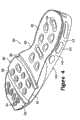
图4为第一鞋底组件的第三透视图。4 is a third perspective view of the first sole assembly.
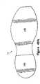
图5为第一鞋底组件的俯视图。Figure 5 is a top view of the first sole assembly.
图6为第一鞋底组件的仰视图。Figure 6 is a bottom view of the first sole assembly.
图7为第一鞋底组件的第一侧视图。Figure 7 is a first side view of the first sole assembly.
图8为第一鞋底组件的第二侧视图。Figure 8 is a second side view of the first sole assembly.
图9A-9E为由图5中的剖面线9A-9E确定的、第一鞋底组件的剖面图。9A-9E are cross-sectional views of the first sole assembly, as determined by
图9F为由图7中的剖面线9F-9F确定的、第一鞋底组件的剖面图。9F is a cross-sectional view of the first sole assembly, as determined by
图9G为鞋制品的、由图1中的剖面线9G-9G确定的剖面图。9G is a cross-sectional view of the article of footwear, as defined by
图10为第一鞋底组件的第一分解透视图。Figure 10 is a first exploded perspective view of the first sole assembly.
图11为第一鞋底组件的第二分解透视图。Figure 11 is a second exploded perspective view of the first sole assembly.
图12A为用于成型第一鞋底组件的模具的上模具部分的俯视图。12A is a top view of the upper mold portion of the mold used to mold the first sole component.
图12B为上模具部分的侧视图。Figure 12B is a side view of the upper mold section.
图13A为模具的下模具部分的俯视图。Figure 13A is a top view of the lower mold portion of the mold.
图13B为下模具部分的侧视图。Figure 13B is a side view of the lower mold section.
图14A-14E表示成型第一鞋底组件的各生产步骤。Figures 14A-14E illustrate the various production steps for molding the first sole component.
图15为根据本发明的第二鞋底组件的透视图。Figure 15 is a perspective view of a second sole assembly according to the present invention.
图16为第二鞋底组件的分解透视图。Figure 16 is an exploded perspective view of the second sole assembly.
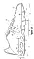
图17为根据本发明的第三鞋底组件的透视图。Figure 17 is a perspective view of a third sole assembly according to the present invention.
图18为第三鞋底组件的分解透视图。Figure 18 is an exploded perspective view of the third sole assembly.
图19为第三鞋底组件的另一实施例的透视图。Figure 19 is a perspective view of another embodiment of a third sole assembly.
图20为表示第三鞋底组件的再一实施例的鞋的侧视图。Fig. 20 is a side view of a shoe showing still another embodiment of the third sole unit.
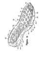
图21为第三鞋底组件的俯视图。Figure 21 is a top view of the third sole assembly.
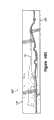
图22为根据本发明的具有第五鞋底组件的鞋制品的外侧视图。22 is a lateral view of an article of footwear with a fifth sole assembly according to the present invention.
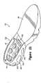
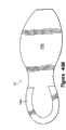
图23为第五鞋底组件的透视图。23 is a perspective view of a fifth sole assembly.
图24为根据本发明的具有第六鞋底组件的鞋制品的外侧视图。24 is a lateral view of an article of footwear with a sixth sole assembly according to the present invention.
图25为根据本发明的第七鞋底组件的透视图。Figure 25 is a perspective view of a seventh sole assembly according to the present invention.
图26为根据本发明的第八鞋底组件第一侧视图。Figure 26 is a first side view of an eighth sole assembly according to the present invention.
图27A和27B为图26中剖面线27A和27B确定的、第八鞋底组件的剖面图。27A and 27B are cross-sectional views of the eighth sole assembly, as defined by
图28为与图9E一致的剖面图,表示第一鞋面组件的另一实施例。28 is a cross-sectional view consistent with FIG. 9E showing another embodiment of the first upper component.
图29A和29B为与图9C一致的剖面图,表示第一鞋面组件的再一实施例。29A and 29B are cross-sectional views consistent with FIG. 9C showing yet another embodiment of the first upper component.
图30A和30B为根据本发明的第九鞋面组件的侧视图。30A and 30B are side views of a ninth upper component in accordance with the present invention.
图31A和31B为根据本发明的第十鞋底组件的侧视图。31A and 31B are side views of a tenth sole assembly according to the present invention.
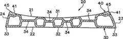
图32为根据本发明的第十一鞋底组件的穿过鞋跟区域的剖面图。Figure 32 is a cross-sectional view through the heel region of an eleventh sole component according to the present invention.
图33为根据本发明的第十二鞋底组件的侧视图。Figure 33 is a side view of a twelfth sole assembly according to the present invention.
图34为根据本发明的第十三鞋底组件的侧视图。Figure 34 is a side view of a thirteenth sole assembly according to the present invention.
图35A和35B为图34中剖面线35A和35B确定的、第十三鞋底组件的剖面图。35A and 35B are cross-sectional views of the thirteenth sole assembly, as defined by
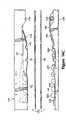
图36为第十三鞋底组件与鞋外底一起的侧视图。Figure 36 is a side view of the thirteenth sole assembly together with the outsole.
图37A和37B为图36中剖面线37A和37B确定的、第十三鞋底组件和鞋外底的侧视图。37A and 37B are side views of a thirteenth sole assembly and outsole, as defined by
图37C为与图37B一致的剖面图,表示一替代构造。Figure 37C is a cross-sectional view consistent with Figure 37B, showing an alternative configuration.
图38为根据本发明的具有第十四鞋底组件的鞋制品的外侧正视图。38 is a lateral elevational view of an article of footwear having a fourteenth sole assembly according to the present invention.
图39A和39B为第十四鞋底组件的侧视图。39A and 39B are side views of a fourteenth sole assembly.
图40A和40B为鞋外底的示意性的仰视图。40A and 40B are schematic bottom views of outsoles.
具体实施方式Detailed ways
介绍introduce
以下论述和附图披露了适用于鞋的鞋底组件的各种实施例。另外,还披露了一种制造鞋底组件的方法。披露了具有适于跑步的构造的鞋、涉及鞋底组件和制造方法的各种构思。该鞋底组件不仅仅限于为跑步而设计的鞋,可以应用于运动鞋类型的大的范围,包括例如蓝球鞋、多功能训练鞋、散步鞋、网球鞋、足球鞋和远足鞋。该鞋底组件还可以应用于一般被认为是非运动的鞋类型,包括正装鞋、皮便鞋(loafers)、凉鞋和工作鞋(workboots)。因此,这里披露的构思可应用于大范围的多种鞋类型。The following discussion and accompanying figures disclose various embodiments of sole assemblies suitable for use in footwear. Additionally, a method of manufacturing a sole assembly is disclosed. A shoe having a configuration suitable for running, various concepts related to sole assemblies and methods of manufacture are disclosed. The sole assembly is not limited to shoes designed for running, but can be applied to a wide range of sports shoe types including, for example, basketball shoes, multi-training shoes, walking shoes, tennis shoes, soccer shoes and hiking shoes. The sole assembly may also find application in shoe types generally considered non-athletic, including dress shoes, loafers, sandals, and workboots. Accordingly, the concepts disclosed herein are applicable to a wide variety of shoe types.
鞋制品10,如图1所表示,包括鞋面11和鞋底结构12。鞋面11可以包括缝合或粘结在一起的多种材料元件(例如纺织品、泡沫和皮革),以形成用于安全地和舒适地接收脚的内部空间。材料元件可以根据鞋面11进行选择和定位,以选择性地获得例如耐久性、透气性、耐磨性、弹性和舒适性等性能。另外,鞋面11可以包括鞋带,用于以惯常的方式改变内部空间的大小,从而在内部空间内固定脚,并使脚容易地进入和移出内部空间。鞋带可以穿过鞋面11上的孔延伸,鞋面11的鞋舌部分可以在内部空间和鞋带之间伸展。因此,在本发明的范围内,鞋面11可以具有实质上常规的构造。An article of
鞋底结构12固定至鞋面11并包括鞋中底13和鞋外底14。如背景技术部分所论述,常规的鞋中底主要由聚合物泡沫材料制成,例如聚亚胺酯或乙基醋酸乙烯酯。与常规鞋中底的结构不同,鞋中底13包括了鞋底组件20,如图2-11所表示,其包括充有流体的囊30和外部加固结构40。在跑步、走路或其它走动活动过程中,鞋10撞击地面时,鞋底组件20减小地面反作用力。另外,鞋底组件20可以提供稳定性或控制脚的运动,例如前旋度(degree of pronation)控制。鞋外底14固定到鞋中底13的下表面,由适合接触地面的、耐久耐磨的材料制成。鞋底结构12可以还包括鞋内底18,具有薄鞋垫部件构造。鞋内底18可以安置在由鞋面11形成的内部空间内,其位置接触脚的跖面,因此增强鞋10的整体舒适性。
以下论述涉及基于相互位置的鞋10、鞋面11和鞋底结构12的各种大致的区域(general regions)。为说明的目的,鞋10可以分成三个大致的区域:脚前区域(forefoot region)15、脚中区域(midfoot region)16和脚后跟区域(heel region)17,如图1所示。脚前区域15一般包括鞋10的对应脚趾和连接跖骨和趾骨的结合部位的部分。脚中区域16一般包括鞋10的对应脚的拱形区域的部分,脚后跟区域对应脚的后部包括跟骨。区域15-17不是要精确的划分鞋10的区域。相反地,区域15-17意在表示鞋10的大致区域,以利于下面的论述。除了鞋10外,区域15-17还可以应用于鞋面11、鞋底结构12和其中的单个元件。The following discussion refers to various general regions of
鞋底组件结构Sole Component Structure
鞋底组件20包括上表面21和相对的下表面22。上表面21以例如粘接的常规的方式与鞋面11固定,并且其在轮廓上可以与脚底表面的形状相一致。因此,上表面21可以表现为脚后跟区域15的高度大于脚前区域15,而脚中区域16在两个高度之间形成过渡。鞋底组件20的整个厚度上的差异,表现为脚后跟区域15的高度大于脚前区域15的高度。通常,鞋底组件20的厚度的范围可以为,例如,从脚前区域15的最前端部分0.15英寸到在脚前区域15和脚中区域16的界面的大约0.70英寸。类似地,鞋底组件20的厚度范围可以为,例如从0.70英寸到脚后跟区域17的大约1.20英寸。
如俯视图图5和图6所示,鞋底组件20的整体形状与脚的形状一致。因此,脚后跟区域17的宽度可以小于脚前区域15的宽度,以适应脚的宽度尺寸的变化。鞋外底14也以例如粘接的常规的方式与下表面22固定。除了上表面21和下表面22外,鞋底组件20还包括外侧表面23和相对的中间侧(medial side)表面24。两个侧表面23和24暴露在鞋中底13的部分,并且从脚后跟区域17到脚前区域15具有渐缩的构造,以便利脚后跟区域17和脚前区域15之间的高度差异。As shown in the top views of FIGS. 5 and 6 , the overall shape of the
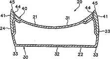
囊30的主要元件有上障壁层31和下障壁层32,其实质上不能渗透囊30中的加压流体。上障壁层31和下障壁层32沿其各自的外边缘粘接一起,以形成外围结合物33并协同形成密封腔,加压流体即位于该腔中。囊30中包含的加压流体引起向外的压力到障壁层31和32上,该向外的压力趋于分开或向外挤压障壁层31和32,因此使障壁层31和32扩张。为了限制由于加压流体的向外的压力使障壁层31和32外向胀大(即膨胀)的程度,在障壁层31和32之间形成有多个内部结合物(bonds)34。内部结合物34从侧表面23和24向内隔开,并且内部结合物34在整个鞋底组件20上分布。如果没有内部结合物34,加压流体引起的向外的压力会引起囊30成一圆形或凸起的构造,特别是在上表面21和下表面22的位置。无论如何,内部结合物34限制障壁层31和32在向外方向上胀大或膨胀的程度并保持上表面21和下表面22的预期的轮廓。The main elements of
在本发明的范围内,内部结合物34可以表现出各种构造。内部结合物34在脚后跟区域17形成的缩进(indentations)的深度大于其在脚前区域15形成的,以在后脚后跟区域17增加鞋底组件20的整体厚度。另外,脚后跟区域17的各内部结合物34的面积一般都大于脚前区域15的各内部结合物34的面积。内部结合物34在上表面21和下表面22的位置也可以不同。例如,内部结合物34可以位于接近上表面21、表面21和22之间的居中位置或在接近下表面22的位置。Within the scope of the present invention,
在跑步或行走过程中,鞋底组件20一般弯曲或折曲以适应脚的自然弯曲,特别是脚前区域15。为了促进鞋组件20的弯曲,在囊30中形成有一对弯曲缩进35。每一弯曲缩进35横向地延伸越过囊30的较低部分(lower portion)。换句话说,弯曲缩进35在侧表面23和24之间延伸,并且弯曲缩进35形成于下表面22。弯曲缩进35的位置也根据脚的跖骨和与其最接近的趾骨之间的结合部位的平均位置选择。特别地,两个弯曲缩进35隔开,即一个弯曲缩进35位于跖骨和与其最接近的趾骨之间的结合部位的前方,而另一个弯曲缩进35位于跖骨和与其最接近的趾骨之间的结合部位的后方。弯曲缩进35的具体位置可以选择,例如如根据解剖学统计资料所确定的,距离跖骨和与其最接近的趾骨之间的结合部位的平均位置三个标准离差(standard deviations)。但是,弯曲缩进35的具体位置可以根据鞋底组件20的具体形状与所需用途而与上述位置有很大的不同。During running or walking,
弯曲缩进35横向,(即在侧表面23和24之间)延伸越过下表面22。尽管,该构造适于结构上用于跑步和各种其它运动活动的鞋,在结构上用于例如蓝球、网球或交叉训练的的运动活动的鞋中,弯曲缩进35可以在大体上纵向方向上(即在脚前区域15和脚后跟区域17之间)延伸。因此,弯曲缩进35可以在各种方向上延伸,以在鞋底组件20中提供确定的弯曲线。图中还示出了完全越过囊30延伸的弯曲缩进35。在某些实施例中,而是,弯曲缩进35可以仅部分地越过囊30的一部分延伸。
弯曲缩进35定义具有减小厚度的鞋底组件20的部分。已知,弯曲物体所需的力度一般取决于物体的厚度,鞋底组件20在弯曲缩进35区域的减小的厚度有利于弯曲。另外,部分的鞋外底14可以延伸进弯曲缩进35,从而形成鞋底结构12的较硬的、难压缩的区域,其也可促进环绕弯曲缩进35的弯曲。
弯曲缩进35在对应于各内部结合物34的位置的下表面22形成缩进。参照图9D,其示出了通过一个弯曲缩进35的剖面。关于该区域,内部结合物34向下延伸粘接上障壁层31和定义弯曲缩进35的下障壁层32的一部分。某些已有技术的囊包括形成弯曲点的结合物,弯曲点可能形成相对硬的区域,因为在弯曲点区域没有流体垫(fluid cushion)。这就是说,弯曲点一般形成已有技术的囊的无垫区域。与已有技术的弯曲点相比,弯曲缩进35,在内部结合物34到弯曲缩进35的连接部分之间的区域形成囊30的充有流体的部分。换句话说,弯曲缩进35和上障壁层31之间形成有空间,其包括流体以使弯曲缩进35提供既适应弯曲又能提供地面反作用力减小的优点。作为选择,可以不在定义弯曲缩进35的区域形成内部结合物34。
多种热塑性聚合物材料可以用于囊30,特别是障壁层31和32,包括聚亚胺酯、聚酯、聚酯聚氨酯(polyester polyurethane)和聚醚聚氨酯(polyether polyurethane)。另一种适合于囊30的材料为由热塑性聚亚胺酯和乙烯-乙烯醇共聚物(ethylene-vinyl alcohol copolymer)交叠层(alternatinglayers)构成的薄层,如Mitchell(美切尔)等人的第5,713,141和5,952,065号美国专利所披露,其全部内容引用于此。也可以利用该材料的一个变更,其中中心层由乙烯-乙烯醇共聚物制成,邻近该中心层的两层由热塑性聚亚胺酯制成,外层由热塑性聚亚胺酯和乙烯-乙烯醇共聚物的磨配材料(regrind material)制成。囊30还可以由柔性微层膜(microlayermembrane)制成,该微层膜包括交替的气体障壁材料和弹性材料,如Bonk等人的第6,082,025和6,127,026号美国专利所披露的,上述专利引用于此。另外,可以利用众多的热塑性聚胺酯橡胶(urethanes),例如陶氏化学公司(Dow Chemical Company)的产品PELLETHANE(热塑性聚氨酯弹性体)、巴斯夫公司(BASF Corporation)的产品ELASTOLLAN(热塑性聚氨酯弹性体)、B.F.Goodrich公司(B.F.Goodrich Company)的产品ESTANE(埃斯坦,聚氨基甲酸乙酯弹性纤维)、其全部为酯或醚基的。还可以使用基于聚酯、聚醚、聚己酸内酯和聚碳酸酯大粒凝胶(polycarbonatemacrogels)的其它热塑性聚胺酯橡胶,或可以使用各种氮塞(nitrogenblocking)材料。另外的适宜的材料由Rudy的第4,183,156和4,219,945号美国专利所披露,其全部内容引用于此。另外的适宜的材料包括含有结晶质材料的热塑性薄薄膜,如Rudy的第4,936,029和5,042,176号美国专利所披露,其全部内容引用于此,聚亚胺酯包括聚酯多元醇(polyesterpolyol),如Bonk等人的第6,013,340、6,203,868和6,321,465号美国专利所公开,其全部内容引用于此。A variety of thermoplastic polymer materials can be used for
囊30内的流体可以为Rudy的第4,340,626号美国专利所披露的任何气体,该专利的全部内容引用于此,例如六氟乙烷(hexafluoroethane)和六氟化硫(sulfur hexafluoride)。该流体还可以包括例如压缩全氟丙烷(octafluorapropane)、氮气或空气的气体。除了气体,可以在囊30内密封各种凝胶体(gels)或液体(liquids)。因此,多种流体适用于囊30。关于压力,适宜的流体压力为15磅每平方英寸,但是范围可以是0到30磅每平方英寸。因此,囊30内的流体压力可以相应的高,或者在本发明某些实施例中,流体压力可以与环境压力(ambient pressure)相等或略高于环境压力。The fluid within
加固结构40形成粘接或固定到囊30的外部的加固罩架(cage)。通常,加固结构40一般沿囊30外围的四周部分延伸,加固结构40的部分沿鞋底组件22的侧表面23和24延伸。因此,加固结构40在上表面21和下表面22之间延伸。另外,制成加固结构40的材料比制成囊30的材料表现出更高的弹性模量。因此,加固结构40的构造特性和材料特性加固鞋底组件20。The
如上面讨论的,内部结合物34从侧表面23和24向内隔开,以限制障壁层31和32外向胀大(即膨胀)的程度,特别是在与上表面21和下表面22相应的区域。内部结合物34可能不能显著地限制侧表面23和24的外向胀大。因此,加固结构的一个目的是限制在侧表面23和24的外向胀大的程度,从而保持鞋底组件20的预定的形状。As discussed above, the
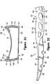
加固结构40包括上部41、下部42和多个连接部43。上部41一般表现为U形构造,位于上表面21和外侧表面23及24的界面。因此,上部41沿侧表面23从脚前区域15向脚后跟区域17延伸,并围绕脚后跟区域17延伸,并且还沿中间侧24从脚前区域15向脚后跟区域17延伸。下部42一般也表现为U形构造,并位于上表面21和侧表面23及24的界面。尽管上部41沿整个上表面21和侧表面23及24延伸,下部42在侧表面23和24延伸。换句话说,下部42覆盖侧表面23和24邻近下表面22的区域,但是下部42一般延伸不到下表面22。下部42穿过脚后跟区域17延伸并可以延伸到脚中区域16。如附图所示,然而,下部42延伸不到脚前区域15。连接部43沿侧表面23和24延伸,并且还在上部41和下部42之间延伸。连接部43在上部41和下部42之间沿倾斜方向延伸。更具体地,连接部43表现为向前倾斜的构造,但也可以为实质上垂直或向后倾斜。The reinforcing
上部41、下部42和连接部43共同形成多个孔来暴露囊30的一部分。孔至少在脚后跟区域17沿侧表面23和24延伸,孔的形状一般取决于连接部43的方向和上部41及下部42的构造。形成在整个加固结构40的孔具有多种形状,包括例如:平行四边形、卵形、六边形、三角形、圆形或各种非几何形状。孔的形状会影响加固结构40的压缩特性,并可以选择,从而为加强结构提供特定的性质。The
加固结构40限制侧表面23和24外向胀大的程度,从而保持鞋底组件20的预定的形状。也就是说,囊30中的加压流体将障壁层31和32向外压,加固结构40限制侧表面23由于流体作用的膨胀。因此,加固结构40的一部分置于加压流体的张力下。尽管上部41和下部42会经受这种张力,沿侧表面23和24延伸的连接部43一般会经受更大程度的张力。因此,连接部43置于流压压力引起的张力下,并起限制侧表面23和24在向外的方向上胀大或膨胀的程度的作用。Reinforcing
如图2-11所示,并论述于上的加固结构40的具体构造,是便于理解本发明的一个实施例的加固结构40。但是,在本发明的进一步的实施例中,加固结构40的构造可以显著地改变,例如,上部41可以限制在后脚跟区域17和脚中区域16,上部41可以中在上表面21的一部分延伸,或上部41可以仅在侧表面23和24的一部分延伸。类似地,下部42可以穿过区域15-17的每一区域延伸,或下部42可以在下表面22的一部分延伸。连接部43可以还表现为在脚中区域16和脚前区域15沿侧表面23和24延伸的构造,并且,连接部43的数量和尺寸可以显著的不同。因此,在本发明的范围内加固结构40可以具有多种构造。As shown in FIGS. 2-11 , and discussing the specific structure of the reinforcing
加固结构40凹进入囊30,如此加固结构40的外向表面大体上与囊的表面21-24平齐。参照图9F,其表示穿过鞋底组件20的一部分的剖面图。如该剖面图所示,连接部43的向外表面大体上与外侧表面23平齐。因此,侧表面23形成接收连接部43的凹进。也就是说,侧表面23弯曲进囊30以形成安置连接部43在凹陷。如此,加固结构40的各种外向表面大体上与囊30的表面21-24平齐。形成加固结构40的各种外向表面大体上与囊30的表面21-24平齐,为鞋底组件20提供平坦的外部构造的优点。但是,在本发明的某些实施例中,加固结构40的外向表面可以插进或凹进囊30中,或可以从囊30中向外凸出。Reinforcing
各种接收加固结构40的凹进表示在分解图10中。更具体地说,囊30定义第一凹进51、第二凹进52和多个第三凹进53。第一凹进51对应上部41的位置,并因此在上表面21的周边附近延伸。部分的第一凹进51还在上表面21和侧表面23及24的界面沿侧表面23和24延伸。第二凹进52对应下部42的位置,并因此邻近在脚后跟区域17和部分的脚中区域16的外围结合物33安置。另外,多个第三凹进53在第一凹进51和第二凹进52之间延伸,以对应连接部43的位置。Various recesses to receive the
可以利用例如注射成型(injection-molding)工艺或压缩模塑(compression-molding)工艺用各种材料制成加固结构40。适合于加固结构40的材料包括聚酯、热固性氨基甲酸乙酯、热塑性氨基甲酸乙酯、尼龙类、上述材料的混合物或包括玻璃纤维的混合物。另外,加固结构40可以由高挠曲模数的聚醚嵌段酰胺(polyether block amide)制成,例如:阿托菲纳公司(Atofina Company)生产的PEBAX。聚醚嵌段酰胺提供有益于本发明的多种性能,包括低温下的高冲击阻力,在负40摄氏度到正80摄氏度的温度范围内性质变化很小,对多种化学物质抗降解,交替弯折(alternative flexure)时的低滞后性。另一种适合于加固结构40的材料是聚对苯二甲酸丁二醇酯(polybutylene terephthalate),例如杜邦公司(E.I.duPont de Nemours and Company)生产的HYTREL。也可以通过将玻璃纤维或碳纤维混入上面论述的聚合物材料制成混合材料,以提高加固结构40的强度。
如上面所论述的,制成加固结构40的材料比制成囊30的材料显示出更高的弹性模量。制成囊30的材料一般是弹性的,而制成加固结构40的材料会显示出半刚性或刚性性质。囊30和加固结构40的比较还是会涉及熔点和再结晶温度(recrystalization temperatures)。如下面详细的论述,制成囊30的材料和制成加固结构40的材料通过模塑工艺(molding process)结合。尽管囊30和加固结构40的熔点和再结晶温度会有显著地不同,熔点差异小于35摄氐度及再结晶温度差异至少5摄氐度会对有利于生产工艺。在某些实施例中,制成囊30的材料的极限拉伸强度小于制成加固结构40的材料的极限拉伸强度。As discussed above, the material from which
尽管加固结构40可以由单种材料制成,在本发明的某些实施例中,两种或多种材料可以组合在加固结构40中。例如,上部41可以由显示出比制成下部42和连接部43的材料的硬度低的材料制成。该构造提供邻近鞋面11的更柔软的材料,其可以增加鞋10的舒适性并促进鞋底结构12和鞋面11的粘接。对应外侧表面23的部分的加固结构40也可以由比对应中间侧表面24的部分的加固结构40硬度更小的材料制成。另外,某些实施例可以改变加固结构40的全部材料,以为加固部分40的特定部分提供特定的压缩、稳定和弹性性能。Although reinforcing
如上所述,在跑步、行走或其它走动活动过程中鞋10撞击地面时,鞋底组件20提供地面反作用力的减小。另外,鞋底组件20可以为脚运动提供稳定性或其它控制,例如前旋度控制。鞋底组件20提供的地面反作用力减小程度,以及鞋底组件20控制脚运动的方式,主要取决于囊30和加固结构40的构造及制成囊30和加固结构40的材料的性质。因此,囊30和加固结构40的构造及其所使用的材料的改变,都可以用于调整或控制地面反作用力减小及鞋底组件30的运动控制性质。鞋底组件20构造以控制地面反作用力减小和鞋10动运动控制性能的方式,将在下面的文字中作详细的论述。As noted above,
下表面22在鞋底组件的后侧部分(rear-lateral portion)形成有向上倾斜区域25,以允许鞋在脚后跟撞击后,向前和向中间侧平滑地旋转。如图1、6和7所示,部分的囊30和形成外侧表面23的加固结构40的垂直厚度在脚后跟区域17后部分减小。形成倾斜区域25的厚度减小的基本原理,与跑步过程中脚的典型运动有关,其过程如下:最初,脚后跟撞击地面,然后是脚的圆形部分(the ball of the foot)。脚后跟离开地面时,脚向前旋转所以脚趾发挥接触作用,最后整个脚离开地面开始下一个循环。在脚与地面接触并向前旋转期间,还伴随着从外侧或侧面向里面或中间旋转,该过程被称为前旋。当脚在空中并准备下一个循环,,被称为后旋的相反的过程发生。The
倾斜区域25的优点是,允许鞋10从脚后跟撞击位置,其中仅有鞋底结构12的后侧部分与地面接触,向脚的实质部分与地面接触的位置平稳过渡。也就是说,倾斜区域25允许鞋10在脚后跟撞击后,向前和向中间侧平滑地旋转。与囊30一样,加固结构40的厚度也被减少以形成倾斜区域25。此外,连接部43的位置可以选择以使倾斜区域25位置的两相邻的连接部43之间形成间隔。相邻的连接部43之间的间隔,通过在倾斜区域25的位置为鞋底组件20提供更大的可压缩性,进一步促进从脚后跟撞击位置的平滑过渡。The sloped
鞋底组件20的特定区域的可压缩性影响鞋底组件20的地面反作用力减小和运动控制性质。通常,将鞋底组件制成外围区域(即,邻近侧表面23和24的区域)比内部区域可压缩性小,可增加鞋底组件20的稳定性。在鞋底组件20中外围可压缩性减小的一种方式可通过加固结构40实现。绕鞋底组件20的外围的加固结构40的位置,加上形成加固结构40的材料的半刚性、低弹性特性,可起减小外围的可压缩性的作用,从而增加稳定性。The compressibility of specific regions of
各种内部结合物34的分布和构造也会影响鞋底组件20的可压缩性和弹性。通常,内部结合物34从侧表面23和24向内间隔,且内部结合物34彼此地相互间隔。内部结合物34在囊30中形成缩进。表面21和22总体上是水平的,而形成障壁层31和32的材料在总体上垂直方向延伸,以形成内部结合物34的缩进。在鞋底组件20压缩时,形成内部结合物34的垂直延伸的材料也压缩、弯曲或变形,从而减小在直接邻接内部结合物34的区域内的鞋底组件20的可压缩性。也就是说,内部结合物34的出现减小在直接邻接内部结合物34的区域内的鞋底组件20的可压缩性。The distribution and configuration of various
将脚从外面或外侧向内部或中间侧旋转的前旋是跑步是脚的自然运动。但是一些人前旋到通常认为是不希望的程度,因此,鞋底组件20的构造可以限制前旋的程度。如上面所论述,内部结合物34减小鞋底组件在特定区域的可压缩性。通过在鞋底组件20的中间侧布置大量的,例如内部结合物34,可以减小中间侧的可压缩性。因为脚从外侧向中间侧旋转,增加的可压缩性可以作用为限制脚的前旋程度。因此,可以选择内部结合物34的分布以控制脚的例如前旋的运动。Pronation, which turns the foot from the outside, or outside, to the inside, or medial side, is running is a natural movement of the foot. However, some individuals pronate to a degree that is generally considered undesirable, and therefore, the configuration of
鞋底组件20的地面反作用力减小和运动控制特性也会受到加固结构40的构造的影响。可以选择上部41、下部42和连接部43的尺寸,以为部分的加固结构40提供特定等级的弹性和可压缩性。例如,鞋底组件20的外围区域的可压缩性可以通过上部41的整体厚度的改变来选择。类似地,脚后跟区域17的可压缩性可以通过连接部43在尺寸或数量上的改变选择。加固结构40的厚度在上部41和下部42之间也可以为渐缩的,以控制加固结构40的可压缩性或限制压缩过程中加固结构折皱或弯曲程度。另外,例如,连接部43的中间区域可以比上或下部厚,以提供特定的可压缩性。在本发明的某些实施例中,加固结构40可以由两种或多种材料制成。如上面所论述的,让鞋底组件20具有表现出较小的中部可压缩性的结构可以减小脚的前旋程度。因此,为加固结构40的外侧选择的材料可以比为加固结构40的中间侧选择的材料具有更小的弹性模量,从而减小中间侧的可压缩性。The ground reaction force reduction and motion control characteristics of
制造工艺manufacturing process
适合于鞋底组件20的一种制造工艺使用模具100,如图12A-13B所示。模具100包括上模具部分110和相应的下模具部分120。当结合一起时,模具110和120形成空腔,该空腔具有实质上等于鞋底组件20的外部尺寸的尺寸。模具100可以用于热成型(thermoforming)囊30,并同时粘接或固定加固结构40到囊30的外部。通常,加固结构40置于上模具部分110内,两片热塑性聚合物薄片置于模具部分110和120之间。然后热塑性薄片吸入模具100的轮廓,两片热塑性薄板的至少一片接触并粘接到加强结构40。另外,模具部分110和120压缩热塑性薄片至一起以形成外围结合物33。一旦热塑性薄片已与囊30的形状一致,加固结构40即粘接到热塑性薄片上,外围结合物形成,囊30可以用流体加压并密封,从而形成鞋底组件20。One suitable manufacturing process for
上模具部分110分别表示于图12A和12B,包括空腔111,其形成与上表面21和侧表面23及24一致的鞋底组件20的各部分。脊部112绕空腔111延伸,并形成部分的外围结合物33。另外,多个凸起113从空腔111的表面延伸,并形成部分地内部结合物34。因此,上模具部分110的位于脊部112限制的(bounded)区域的部分,形成上表面21和侧表面23及24。脊部112的扩展从空腔111向外延伸,并形成L形通道114。如下面详细的论述,通道114用来形成管道(conduit),通过该管道可以将流体注入鞋底组件20。上模具部分110的另一个特征是多个槽孔(slot vents)115,分布在整个空腔111。在鞋底组件20的形成过程中,聚合物材料的热塑性薄片吸入上模具部分110的轮廓时,孔115为空气提供出口。
下模具部分120分别表示于图13A和13B,包括表面121,其形成与下表面22对应的鞋底组件的部分。脊部122绕表面121延伸,并与脊部112结合,形成外围结合物33。另外,多个凸起123从表面121延伸,并结合凸起113形成内部结合物34。因此,下模具部分120的位于脊部122限制的区域的部分,形成下表面22。脊部122的扩展从表面121向外延伸,并形成L形通道124。通道124结合通道114形成管道,通过该管道可以将流体注入鞋底组件20。下模具部分120的另一个特征是多个槽孔125,分布在整个表面121。在鞋底组件20的形成过程中,聚合物材料的热塑性薄片吸入下模具部分120的轮廓时,孔115为空气提供出口。
下面将论述利用模具100由加强结构40和障壁层31和32形成鞋底组件20的方法。例如,可以利用注射成型工艺由上面述论的材料形成加固结构40。然后用例如清洁剂或酒精清洁加固结构40,以除去表面杂质,例如脱膜剂或指纹。还可以等离子处理加固结构40的表面,以增加与囊30的粘接。A method of forming
在成形和清洁后,加固结构40被置于模具部分110和120之间,然后放上上模具部分110,如图14A和14B相应地所示。如上述文字的论述,上模具部分110形成与上表面21和侧表面23及24相应的鞋底组件20的部分。在上面实施例所论述的鞋底组件20中,加固结构40通常粘接到上表面21和侧表面23及24。因此,将加固结构40置于上模具部分110,如图14B所示,适当的放置加固结构40于上模具部分110中以成形鞋底组件20。可以利用各种技术来固定加固结构40和上模具部分110,包括:例如,真空系统、多封口(various seals)、非永久性粘接元件。另外,加固结构40可以包括各种定义开孔的接片,上模具部分110可以包括凸起,其啮合上述开孔以固定加固结构40和上模具部分110。After forming and cleaning, the reinforcing
多个管道可以延伸穿过模具100,以引导例如水的热的流体穿过模具100。热的流体将整个模具100的温度升高至大约180华氏度。如上所述,加固结构40置于模具100中,并从模具100上导热,因此加固结构40的温度升高至大约180华氏度。在本发明的某些实施例中,可以在放置加固结构40到模具100中之前将其加热,以减少制造时间。A plurality of pipes may extend through the
在将加固结构40放置入上模具部分110后,加热形成障壁层31和32的一对热塑性聚合物薄片,然后将其置于模具部分110和120之间,如图14C所示。障壁层31和32被加热到的温度取决于所使用的特定的材料。如上所述的,障壁层31和32可以由多种材料制成,包括热塑性聚亚胺酯和乙烯-乙烯醇共聚物的交替层,其具有350到360华氏度之间的熔化温度。障壁层31和32的表面可以被加热的温度在400到450华氏度之间,该温度一般会熔化障壁层31和32的表面,而内部不熔化。After the reinforcing
在成型之前,上障壁层31的厚度可以比下障壁层32的厚度更厚。尽管在成型之前障壁层31和32可能表现出不同的厚度,但在成型之前障壁层31和32的每一层都可以具有实质上均匀的厚度。在成型之前,适合于上障壁层31的厚度范围为0.045到0.090英寸,一个优选的厚度为0.075英寸;在成型之前,适合于下障壁层32的厚度范围为0.045到0.065英寸,一个优选的厚度为0.055英寸。尽管下障壁层32仅形成下表面22,上障壁层31形成上表面21和侧表面23及24。厚度上有差别的原理是,上障壁层31将伸展至较大的程度以形成上表面21和侧表面23及24。因此,障壁层31和32在伸展前的厚度的原始差异在上障壁层31的薄化中得到补偿,该补偿可能发生在形成上表面21和侧表面23及24过程中上障壁层31的伸展或变形。Before molding, the thickness of the
一旦障壁层31和32被放好,然后这样定位模具部分110和120,脊部112和脊部122对齐,并且多个凸起114对齐凸起123。在该位置,模具部分110和120的形成对应于鞋底组件20的区域定位于障壁层31和32相对侧,并且也对齐。然后模具部分110和120平移彼此靠近,这样模具100接触和压缩障壁层31和32,如图14D所示。Once the barrier layers 31 and 32 are placed, the
当模具100接触并压缩部分障壁层31和32,例如空气的、具有相对于环境空气正压力的流体,可以注入到障壁层31和32之间,以引导障壁层31和32相应的接触并一致于模具110和120的轮廓。可以使用多种方法来加压障壁层31和32之间的区域。例如:可以引导流体通过由通道114和124形成的管道。也就是说,可以放置注射针在障壁层31和32之间以及通道114和124之间,以输送流进管道并进入形成鞋底组件20的区域的流体。空气也可以从障壁层31及32和模具部分110及120之间的区域,通过孔115和125排出,因此吸引障壁层31和32到模具部分110和120的表面。换句话说,在障壁层31及32和模具部分110及120的表面之间,至少可以形成部分真空。另外,吸引障壁层31和32到模具部分110和120的表面也吸引障壁层31和32与加固结构40接触。因此,在该部分制造工艺中,障壁层31和32接触并粘接至加固结构40。When the
当障壁层31和32之间的区域被加压,空气从障壁层31和32之间及从模具部分110和120之间的区域除去,障壁层31和32与模具100的形状相一致并粘接一起。更具体地说,障壁层31和32伸展、弯曲或沿空腔111的表面和表面121延伸,并形成囊30的大体的形状。脊部112和脊部122也压缩障壁层31和32的线性区域,以形成外围结合物33。另外,由于在凸起113和123之间被压缩,障壁层31和32符合凸起113和123的形状并粘接一起,从而形成内部结合物。When the area between the barrier layers 31 and 32 is pressurized, air is removed from between the barrier layers 31 and 32 and from the area between the
尽管障壁层31和32沿空腔111的表面和表面121延伸,上障壁层31通常不接触空腔111被加固结构40覆盖的部分。而是上障壁层31接触并被压缩至加固结构40的内向表面,从而将上障壁层31粘接至加固结构40。参照图9F,连接部43的外向表面总体上与外侧表面23平齐,外侧表面23形成接收连接部43的凹进。也就是说,外侧表面23弯曲入囊20以形成安置连接部43的凹陷。该构造产生于:加固结构40置于上模具部分110中,并且上障壁层31与加固结构40的内向表面压缩、并粘接到加固结构40的工艺。Although the barrier layers 31 and 32 extend along the surface of the cavity 111 and the
加固结构40的各个外向表面大体上与囊30的表面21-24平齐。当空气加压障壁层31和32之间的区域,空气通过孔115和125排出模具100时,上障壁层31和加固结构40均被压至空腔111的表面。上障壁层31接触加固结构40的内表面,形成加固结构40的形状,沿加固结构40延伸,并接触空腔111的表面。如此,加强结构40的表面成形至大体上与囊30的表面21-24平齐。Each outwardly facing surface of
当障壁层31和32符合模具100的形状并粘接一起时,上障壁层31在上部41的位置弯曲以形成侧表面23和24。因此,上障壁层31在大体上水平方向上延伸以形成上表面21,并且上障壁层31在上部41的位置弯曲,以在总体上垂直的方向上延伸并形成侧表面23和24。因此,上障壁层31在成形囊30的工艺期间弯曲,以形成上表面21和侧表面23及24。When barrier layers 31 and 32 conform to the shape of
如图9F所示,加固结构40的边缘表现为倾斜构造以促进加固结构40和囊30之间界面的平齐性(flush nature)。通常,如果例如加固结构40形成为具有无倾斜的矩形横截面,上障壁层31需要在更大程度上伸展,因此导致上障壁层31在邻近加固结构40的区域内不适当的变薄。另外,没有倾斜可能还会导致在上障壁层31和加固结构40之间形成间隙或间隔。因此,加强结构40成形为具有倾斜边缘。As shown in FIG. 9F , the edges of
在形成上障壁层31和加固结构40之间的粘接过程中,空气可能会封闭在上障壁层31和加固结构40之间,从而降低粘接效果,为了使空气易于从上障壁层31和加固结构40之间排出,可以形成多个经过加固结构40的选定的位置的排气孔(vent apertures)44,并可以形成经过与上表面21对应的上表面41的区域,以限制排气孔44的可见性。排气孔为空气提供出口并可以在位置上与上模具110中的各孔115对应。During the bonding process between the
一旦鞋底组件20在模具100中成形,分开模具110和120,以使加固结构40和障壁层31和32可以从模具100中移出,如图14E所示。然后可以冷却形成加固结构40和障壁层31及32的聚合物材料,可以通过通道114和124形成的管道注入加压流体。管道然后被密封以将流体封闭在囊30内。另外,障壁层31和32多余的部分可以从鞋底组件20上修剪或移除掉。该多余的部分可以循环或再利用以形成其它的热塑性薄片。Once
连接部43因加压流体处于紧张状态,作用为限制侧表面23和24外向胀大(即,膨胀)。在加压之前,加固结构40和囊30通常为非紧张状态。然而,加压流体在囊30上施加向外的压力,从而置障壁层31和32处于紧张状态。如果没有加固结构40,障壁层31和32的外向上膨胀程度会导致侧表面23和24处的球形或凸起构造。加固结构40,特别是连接部43限制由加压流体向外的压力引起的外向膨胀。因此,囊30的加压引起连接部43的紧张。Connecting
如上面所论述的,各内部结合物34的分布和构造会影响鞋底组件20的可压缩性。取决于凸起113和123的位置的、内部结合物34的分布和构造的改变,可以用来控制各种脚运动,例如前旋。因此,脚运动可以通过模具部分110和120的改变来控制。通过改变鞋底组件20的整体厚度、各内部结合物34的分布和构造和加固结构40的构造,鞋10还可以构造以在不同的活动中使用,例如跑步、蓝球和足球。鉴于,例如,鞋底组件20的较大的整体厚度适合跑步运动,以提供较大的地面反作用力减小,较小的整体厚度会更适合蓝球和足球运动,以增加稳定性。为跑步运动中,控制前旋也是关键,凸起113和123可以分布和构造以在鞋10准备用作跑步时控制前旋。相反地,当鞋10准备用作蓝球或足球运动时,通过凸起113和123的分布和构造控制的前旋程度可以减小。因此,鞋底组件20的尺寸和构造改变可以用来将鞋10设计为特定的运动活动。As discussed above, the distribution and configuration of each
还可以让内部结合物34的构造影响鞋底组件20的其它性质,例如稳定性。在本发明的某些实施例中,选择的内部结合物34可以具有长形的构造。参照附图,长形的内部结合物34置于脚中区域16和脚后跟区域17的分界面并延长到中间侧(medial-lateral)方向。另外的长形的内部结合物34置于脚后跟区域17。另外的长形的内部结合物34置于脚前区域15可以为纵向方向或中间侧方向。在脚前区域15的前面部分,例如,长形的内部结合物34纵向延伸。与圆形、三角形或其它非长形的内部结合物34相比,长形的内部结合物34表现出增加的抗剪切力,因此增加鞋底组件20的中间到侧面稳定性。因此,形成长形的内部结合物34可以为增加鞋10的整体稳定性的一种方法。The configuration of
各种内部结合物34的伸长程度,也对在内部结合物34区域的鞋底组件20的可压缩性具有影响。通常,圆形内部结合物34比长形的内部结合物34表现出更大的可压缩性。对脚前区域15,许多内部结合物34置于弯曲缩进35之间,表现为圆形构造以增加该区域的可压缩性。在脚前区域15的前方部分,但是许多内部结合物34表现为长形的构造,得以减小该区域的可压缩性。The degree of elongation of the various
涉及内部结合物34的构造的不同特征影响鞋底组件20的整体构造。通常,内部结合物34的间隔从中间到侧面方向为大约0.86英寸,但是在脚前区域15的前方部分可以在0.5到0.6英寸的范围。内部结合物34的间隔在通过脚后跟区域17和部分的脚前区域16、纵向方向上为大约0.98英寸,但是在脚前区域17可以为0.4到0.9英寸的范围。表面21和22之间的过渡形成的半半径和从内部结合物34向内延伸的材料,对内部结合物34的可压缩性具有影响,并一般选择为在0.125和0.150英寸范围内。但是在脚前区域15的前方部分,该半径可以为0.1英寸。Various features related to the configuration of
在鞋底组件20成形后,鞋面11可以固定到上表面21,并且鞋外底14可以固定到下表面22,从而,实质上完成鞋10的制造。可以调节鞋底组件20的表面性质,以促进鞋底组件20与鞋10的其它组件之间的粘接。通常,下表面22和鞋外底14之间的粘接强度,例如,可以通过形成具有相对粗糙纹理的下表面22增强。尽管粘合剂可能不能有效地粘接到整个平滑表面,粗糙表面的纹理可使粘接增强。虽然,给予表面21和22相对粗糙的纹理可以增强粘接,相对粗糙的纹理的缺点是降低通过形成囊30的聚合物材料的可见性。因此,可以给予侧表面23和24相对平滑的纹理以增加鞋底组件20的该部分的可见性,当组合成鞋10时,其可见。鞋底组件20的表面性质通常取决于模具100的表面性质。空腔111和表面121形成上表面21及下表面22的部分可以,因此,不如空腔111的形成侧表面23和24的部分平滑。鞋底组件20的纹理表面还可以增加囊30与加固结构40之间的粘接。在本发明的某些实施例中,加固结构40的内向表面和上障壁层31的接触加固结构40的部分可以在粘接之前进行粗糙化处理。After
如上所述,粘接鞋外底14到下表面22的步骤可以在形成鞋底组件20后执行。可选择地,可以在模具100中定位一个或多个抓地元件,以在热成型工艺过程中在抓地元件和下表面22之间形成结合物。换句话说,抓地元件可以通过与粘接加固结构40到囊30相似的工艺,粘接到囊30。抓地元件可以为一个或多个橡胶材料元件,例如,其构造与常规鞋外底相似。抓地元件还可以为另外的热塑性材料元件,其加强鞋底组件20接触地面的区域。因此,在本发明的范围内,抓地元件可以具有各种构造。As noted above, the step of bonding
加固结构40的上部41沿鞋底组件40的中间和外侧延伸,并提供确定的钳帮线(lasting line)以固定鞋面11到鞋底组件20,如图9G所示。某些鞋底结构的一个问题是,鞋面应当固定到鞋底结构的精确程度,在鞋底结构的构造上不明显。参照剖面图图9A-9E和图9G,加固结构40在鞋底组件20的中间和外侧均形成脊部45。脊部45为确定钳帮表面的可确定的线,因此,确定了鞋底组件20的鞋面11可固定的部分。更具体地说,鞋面11可以固定到粘接(pasting)表面,其为上表面21的位于脊部45之内的部分。因此,粘合剂,例如,可以置于脊45的位于中间和外侧的部分之间,以适当地固定鞋面11到鞋底组件20的钳帮表面。The
模具100的构造方式影响鞋底组件20的最终性质。例如,模具部分110和120的构造对障壁层31和32会发生的伸展程度有影响。如上面所论述的,可以选择障壁层31和32的厚度,以解决模塑过程中伸展的问题。但是,另外,模具部分110和120可以构造有拔模角(draft angles),以限制障壁层31和32的伸展程度,从而控制障壁层31和32的最终厚度。例如,各凸起113和123的拔模角可以在5到8度的范围内,并且可以在脚后跟区域向上延伸13度。The manner in which
模具部分110和120的构造还影响外围结结合物33的布置。在下表面22和侧表面23及24的界面放置外围结合物33的一个优点是,不受障壁的可见性通过侧表面23和24被限制。该构造需要上障壁层31比下障壁层32延伸更大范围,以还形成侧表面23和24。但是,在本发明的进一步的实施例中,外围结合物33可以置于侧表面23和24的中点,或外围结合物33可以置于上表面21和侧表面23及24之间的界面。因此,外围结合物33的高度可以选择,以限制或控制在障壁层31和32的伸展。The configuration of the
内部结合物34的相对高度还影响发生在障壁层31和32的伸展程度。如果,例如,内部结合物34放置于相对于上表面21更接近于下表面22,则上障壁层31必须向下伸展以形成与内部结合物34关联的缩进。相似的,更接近上表面21的定位内部结合物34引起下障壁层32向上伸展形成与内部结合物34关联的缩进。确定模具100的构造时,应当计算在障壁层31和32的伸展程度,并且可以选择凸起113和123的相对高度以增加或减少发生在障壁层31和32区域的伸展程度。因此,各种内部结合物可以分别形成不同的高度以控制在障壁层31和32的伸展。The relative height of the
各种内部结合物34的相对高度也对鞋底组件20的可压缩性有影响。通常,障壁层31和32的厚度与障壁层31和32的硬度成正比。在形成邻近下表面22的内部结合物34时,上障壁层31被向下拖曳并伸展。伸展减小上障壁层31的厚度并减小上障壁层31的硬度,因此,增加可压缩性。可是,在形成邻近上表面21的内部结合物34时,上障壁层31在较小的程度上伸展,因此,增加上障壁层31的厚度并减小可压缩性。The relative heights of the various
在热成形工艺中障壁层31和32伸展时,障壁层31和32的厚度减小。希望的障壁层31和32的最终厚度,一般由鞋10的具体用途和构造确定。选择外围结合物33的位置、内部结合物34的位置和障壁层31和32的最初厚度,可以控制障壁层31和32的伸展程度。因此,可以选择外围结合物33的位置、内部结合物34的位置和障壁层31和32的最初厚度,以在鞋底组件20的每一区域最优化囊30的整体厚度。When the barrier layers 31 and 32 are stretched in the thermoforming process, the thickness of the barrier layers 31 and 32 decreases. The desired final thickness of barrier layers 31 and 32 is generally determined by the specific application and construction of
还可以利用在障壁层31和32处控制延伸程度,为部分的囊30进行加固。通常,囊30的具有较大厚度的区域会比厚度较小的区域更耐久。形成囊30的材料和形成加固结构40的材料之间的弹性模量的差异,会在囊30和加固结构40之间的界面引起磨损。因此,可以控制在障壁层31和32处的伸展程度,以增加邻近加固结构40的区域中的囊30的厚度。如上面所论述的,可以通过多种机制控制在障壁层31和32处的伸展程度,包括:例如模具100的构造,障壁层31和32的相对厚度,和形成内部结合物34的位置。Parts of
障壁层31和32的外向胀大(即,膨胀)程度,归因于内部结合物34限制的加压流体的向外的压力。尽管有内部结合物34,障壁层31和32形成上表面21和下表面22的部分,在密封在囊30中的流体的压力下,会向外弯曲。该向外弯曲有效地弯曲障壁层31和32的部分区域,并且会在形成囊30的热塑性聚合物材料上引起额外的应力。减小形成囊30的热塑性聚合物材料上的应力的一种方法为,模塑或形成包括弯曲表面的障壁层31和32,该弯曲表面与压力作用下将发生的膨胀一致。The extent to which barrier layers 31 and 32 expand outwardly (ie, expand) is due to the outward pressure of the pressurized fluid confined by
尽管热成形为形成鞋底组件20的一种适宜的方法,还可以利用吹塑工艺。通常,适合的吹塑工艺包括放置加固结构40到两个模具部分的至少一个中,以及然后放置型坯(parison)到模具,例如模具部分110和120之间。型坯通常为熔铸的聚合物材料的空心的管状结构。形成型坯时,从模具中挤压出熔铸的聚合物材料。型坯的壁厚可以实质上为常数,或可以沿型坯的周边不同。因此,型坯的剖面图可能表现为不同壁厚的区域。适合于型坯的材料包括上面讨论的囊30的材料。在模具部分之间放置型坯后,模具部分闭合在型坯上,型坯中的加压空气使液化的弹性材料接触模具表面。然后,封闭模具部分并引入加压空气,使液化的弹性材料接触加固结构40的表面。空气也可以从型坯和模具之间的区域排出,以进一步促进模塑和粘接。因此,鞋底组件20也可以通过吹塑工艺制成,其中加固结构40在引入液化的聚合物材料之前置于模具中。Although thermoforming is one suitable method of forming
除了热成型和吹塑技术外,还可以利用各种其它制造技术来形成鞋底组件20。例如,囊30和加固结构40可以分别成形,两种组件可以随后粘接一起。还可以利用双注射(dual-injection)技术来同时由各自的材料形成囊30和加固结构40。在某些实施例中,可以形成与上表面21和侧表面23及24一致的第一元件,与下表面22一致的第二元件可以结合其上,然后与加固结构40一致的第三元件可以固定到外部。因此,可以由多种工艺制成鞋底组件20的具有通常形状的结构和特征。In addition to thermoforming and blow molding techniques, various other manufacturing techniques may be utilized to form
另外的鞋底组件构造Additional sole assembly construction
上面公开的鞋底组件20的具体构造,意在在本发明的范围内提供鞋底组件的示例。然而,也可以利用各种变更构造。参照图15和16,示出的鞋底组件20具有多个桥(bridges)46,该桥46横向越过上表面21延伸。更具体地说,四个桥46在上部41的中间和外侧之间延伸,加强鞋底组件20的稳定性。如图所示,桥46为相对窄的结构与加固结构40形成整体(即,一片)结构,因此,桥46固定到囊30。与加固结构40的其它部分一样,桥46凹进囊30的缩进,并在热成形工艺中粘接到囊30。尽管,桥46表现不相对窄的,根据希望的鞋底组件20的性质,桥46的宽度可以显著的增加,并且桥46可以形成一平面遍布(extends over)脚后跟区域17。此外,桥46可以遍布下表面22或上表面21和下表面22,并且桥46可以延伸通过脚中区域16或脚后跟区域17。因此,在本发明的范围内,桥46的具体构造可以显著的改变。The specific configuration of
除了桥46外,鞋底组件20可以还包括多个外延(extensions)47,如图17和18所示。外延47为加固结构40从鞋底组件20向上延伸的部分。外延47可以固定到鞋面11的外部,或可以在形成鞋面11的材料元件之间延伸、以进一步固定鞋底组件20到鞋面11。外延47可以在脚后跟区域17的脚部附近延伸的一个目的,例如,是为脚提供附加的支撑。因此,外延47可以起到常规的脚后跟稳定器(heel counter)或其它稳定结构的效果。尽管外延47可以表现为图中所示的长形的结构,与常规的脚后跟稳定器的结构的相似的相似位置的杯形结构48,可以成为加固结构40的一部分,如图19所示。在本发明的再一个实施例中,如图20所示,外延47可以由多个鞋带部件49代替,其位置使可在鞋面11的脚背部分延伸并形成接收鞋带的孔。因此,可以利用鞋带部件49作为鞋带系统的一部分,改变内部空间的尺寸,从而将脚固定在内部空间里并方便脚进入和从内部空间移除。In addition to
如上面文字的所披露,囊30形成单一的、密封的腔以封入加压流体。参照图21,其所示出的囊30具有由结合物38隔断的第一腔36和第二腔37。第一腔36通过区域15-17的每一区域延伸,然而第二腔37只限于脚后跟区域17。第二腔37中的流体压力可以小于第一腔36中的流体压力,以使囊30的不同区域表现出不同的地面反作用力减小和可压缩性性质。在进一步的实施例中,囊30可以其其它部分结合两个或多个分开的密封腔。因此,在本发明的范围内,分开的密封腔的构造及腔内流体的压力可以显著地改变。As disclosed in the text above,
常规的运动鞋制品的鞋底结构通常含有(incorporates)聚合物泡沫材料,例如聚亚胺酯或乙基醋酸乙烯酯。聚合物泡沫的一个缺点涉及压缩形变(compression set)概念。当一个人使用一鞋类制品时,鞋底结构反复地被压缩。聚合物泡沫材料通常具有大量充气单元,在反复压缩后,该充气单元可能会破裂或恶化,因此,改变鞋底结构的地面反作用力减小或稳定特性。与常规的鞋底结构相比,如上所述的,鞋底结构12没有并入聚合物泡沫材料。如上所述的,在某些实施例中,聚合物泡沫材料18可以与鞋底组件20结合使用。The sole structure of conventional articles of athletic footwear typically incorporates polymeric foam materials such as polyurethane or ethyl vinyl acetate. One disadvantage of polymer foams relates to the concept of compression set. When a person uses an article of footwear, the sole structure is repeatedly compressed. Polymeric foam materials typically have a large number of air-filled cells that may crack or deteriorate after repeated compression, thereby altering the ground reaction force reduction or stabilization characteristics of the sole structure. In contrast to conventional sole structures, as noted above,
在上面论述的鞋底组件20的各种实施例中,鞋底组件20通过区域15-17的每一区域延伸,因此,在脚的纵向长度的实质部分延伸。参照图22和23,鞋底组件20仅通过脚后跟区域17延伸,聚合物泡沫材料18在脚前区域15和脚中区域16形成中底13。因此,鞋底组件20可以仅通过鞋10的纵向长度的一部分延伸。在进一步的实施例中,鞋底组件20还可以限制在鞋底结构12的单侧。例如,鞋底结构12的外侧可以由鞋底组件20组成,而中间侧由泡沫材料18组成。在再进一步的实施例中囊30的一部分可以由泡沫材料18代替,如此,加固结构40一并沿囊30和泡沫材料18延伸。In the various embodiments of
鞋底组件20可以直接粘接到鞋面11,如图1所示。作为选择,聚合物泡沫材料18可以在鞋底组件20和鞋面11之间延伸,如图24所示。因此,泡沫材料18的上表面可以粘接至鞋面11,鞋底组件20可以粘接到泡沫材料18的下表面。所示的泡沫材料18具有大约鞋底组件20一半的高度,但是泡沫材料18和鞋底组件20的相对厚度可以显著地改变。
为囊30和加固结构40选择的材料可以表现出不同的机械性能,例如弹性模量。然而,除了机械性能外,为囊30和加固结构40选择的材料还可以表现出不同的视觉性能(visual properties)。例如,囊30可以由大体上透明的材料(clear material)制成,但是加固结构40可以由大体上半透明或不透明的材料制成。另外,囊30和加固结构的颜色可以不同。因此,形成鞋底组件20的材料的视觉性能的一些方面可以改变,包括透明性和/或颜色。The materials selected for
图25示出了鞋底组件20′,具有囊30′和粘接到囊30′外部的加固结构40′。同鞋底组件20一样,加固结构40′形成加固罩架,其粘接或固定到囊30′的外部。通常加固结构40′大体上沿囊30′的外围部分延伸,并且部分的加固结构40′顺着囊30′的侧表面延伸。因此,加固结构40′在囊30′的上、下表面之间延伸。另外,形成加固结构40′的材料可以比形成囊30′的材料表现出更高的弹性模量。因此,加固结构40′的构造和材料特性可以加固囊30′。Figure 25 shows a sole assembly 20' having a bladder 30' and a reinforcing structure 40' bonded to the exterior of the bladder 30'. As with
当组合成鞋类制品时,鞋底组件20′可以封装入聚合物泡沫材料,例如聚亚胺酯或乙基醋酸乙烯酯。因此,鞋底组件20′可以取代鞋类制品的常规鞋底结构中的常规的充有流体的囊。可以通过泡沫材料中的孔暴露部分的鞋底组件20′,以达到从鞋的外部的可见性,或者可以通过泡沫材料将整个鞋底组件20′封装起来。鞋底组件20′也可以具有一个以上具有不同压力流体的腔。When assembled into an article of footwear, sole assembly 20' may be encapsulated in a polymeric foam material, such as polyurethane or ethyl vinyl acetate. Thus, sole assembly 20' may replace conventional fluid-filled bladders in conventional sole structures for articles of footwear. Portions of the sole assembly 20' may be exposed through holes in the foam for visibility from the exterior of the shoe, or the entire sole assembly 20' may be encapsulated by the foam. The sole assembly 20' may also have more than one chamber with fluid at different pressures.
对鞋底组件20的结构的另一个考虑涉及鞋底组件20的不同部分的相对可压缩性。在走路、跑步或其它走动活动中,鞋底组件20在地面和脚之间被压缩,部分的鞋底组件20因此而变形。影响鞋10的稳定性的一个因素是,在外加负载下下表面21和侧表面23及24的压缩或变形程度。如果,例如,下表面22邻近外侧表面23的部分比下表面22邻近中间侧表面24的部分的压缩程度更大,鞋底组件20支承脚的外侧的部分可能变的不稳定并允许脚向外侧旋转。在外加负载作用下鞋底组件20表面的压缩或变形程度,可以通过增加补充层(supplemental layer)60限制,如图26-27B所示。另外,补充层60可以减小相对尖锐的物体(例如,石子、刺、钉子)刺破囊30的概率。Another consideration in the structure of
补充层60粘接到下表面22并增加鞋底组件20变形的阻力,因此,鞋10的整体稳定性。如图所示,补充层60不向上延伸、进入与内部结合物34和弯曲缩进35的关联的各轮廓,因此,允许下障壁层32形成轮廓的部分压缩而没有补充层60引入的额外的阻力。但是,在某些实施例中,补充层60可以延伸进入与内部结合物34和弯曲缩进35的关联的各轮廓,或者补充层60可以延伸进入选择的轮廓。作为一个例子,补充层60可以延伸进入最接近中间侧24的轮廓,以抵抗脚的前旋(即,向前旋转)。此外,补充层60可以在与内部结合物34对应的区域定义各种孔。
补充层60还表现为通过整个下表面23延伸。然而在某些实施例中,补充层60的位置在仅在脚后跟区域17,或仅在下表面22邻近中间表面24的部分。补充层60还可以形成有孔,该孔邻近下表面22的边缘放置补充层材料。The
补充层60可以由上面讨论的用于障壁层31和32的任何材料制成。当,例如,障壁层31和32由热塑性聚亚胺酯材料制成时,补充层60也可以由热塑性聚亚胺酯制成以利于各层之间的粘接。补充层60的厚度对鞋底组件20的压缩限制的程度有影响。通常,补充层60的厚度较大提供较大的压缩阻抗,厚度较小提供较小的压缩阻抗。如上面所论述的,在成型之前,下障壁层32的适宜的厚度范围为0.03到0.10英寸,一个优选的厚度为0.055英寸。补充层60可以也具有该范围的厚度,但是根据需要的压缩阻抗的大小,可以从该范围扩展。
鞋底组件20的另一种构造表示在图28中。与图9A、9B和9E所示的、一般水平构造的内部结合物34相比,图28公开的障壁层31和32之间的一对内部结合物34′是倾斜(inclined)或有坡度的(sloped)。如上面所论述的,内部结合物34的相对高度影响发生在障壁层31和32处的伸展程度。如果,例如,内部结合物34放置于比上表面21更接近于下表面22,障壁层31必然向下伸展以形成与内部结合物34关联的缩进。相似的,定位内部结合物34更接近上表面21引起下障壁层32向上伸展形成与内部结合物34关联的缩进。部分的障壁层31和32的伸展程度影响障壁层31和32的厚度。因此,内部结合物34的位置对障壁层31和32的厚度有影响。Another configuration of
内部结合物34′相对于上表面21或下表面22的平面是倾斜的。具体地说,内部结合物34′在远离各自的侧表面23和24的方向上形成向下倾斜的延伸。该方向使内部结合物34′的较高部分邻近侧表面23和24,上障壁层31邻近侧表面23和24的区域伸展成相对小的程度,以形成内部结合物34′。也就是说,由于内部结合物34′构造,上障壁层31的延伸在邻近侧表面23和24的位置减少。在该区域减少的延伸为上障壁层31提供较大的厚度,因此增加上障壁层31邻近侧表面23和24处的耐久性和稳定性。The inner binding 34' is inclined with respect to the plane of the
内部结合物34′的方向使内部结合物34′的较低部分接近鞋底组件20的中间区域,上障壁层31邻近中间位置的区域伸展至相对大的程度以形成内部结合物34′。也就是说,由于内部结合物34′构造,在上障壁层31处的伸展在中间区域增加了。在该区域增加的延伸为上障壁层31提供较小的厚度,因此增加上障壁层31在中间区域的可压缩性。The inner bond 34' is oriented such that the lower portion of the inner bond 34' is proximate to the mid-region of the
结合物在障壁层31和32之间的构造可以与图28所示的具体的构造不同。例如,障壁层31和32之间的所有结合物可以具有与内部结合物34′相似的倾斜构造。在某些鞋类制品中,内部结合物34′的倾向可以反转,这样内部结合物34′在运离各自的侧表面23和24方向上形成向上倾斜的延伸。图28表示在脚前区域15通过鞋底组件20的一部分的剖面,但是障壁层31和32之间倾斜的结合物可以位于鞋10的任意区域。The configuration of the bond between the barrier layers 31 and 32 may differ from the specific configuration shown in FIG. 28 . For example, all bonds between barrier layers 31 and 32 may have a similar sloped configuration as inner bond 34'. In some articles of footwear, the orientation of the inner bond 34' may be reversed so that the inner bond 34' extends upwardly sloping in a direction away from the respective side surfaces 23 and 24. 28 shows a section through a portion of
关于形成鞋底组件20的制造工艺的另一个考虑涉及表面21-24的弯曲程度。图13A和13B表示下模具部分120具有大体上平面(planar)的区域,用来形成下表面22。当鞋底组件20从模具100中移除并时,处于未膨胀和未压缩的状态,因此,下表面22会表现出基本上平面的构造。根据鞋底组件20的受压程度,下表面22可能向外弯曲以使下表面22表现为大体上凸起的构造。为了限制下表面22向外弯曲并表现为大体上弯曲的构造的程度,下模具部分120可以制成以具有用于形成下表面22的弯曲区域,从而给予下表面22在未受压状态下一凹入的形状。Another consideration with respect to the manufacturing process for forming
参照图29A,鞋底组件20表现为未膨胀的构造,并且下表面22表现为大体上凹入的构造。如上所述的,提供具有用于成形下表面22的凸起区域的下模具部分20,可以给予下表面22一凹入的构造。加压后,流体施加向外的压力到下障壁层32并使下表面22变形成大体上平面的构造,如图29B所示。提供具有平面构造的下表面22的一个优点是,因为对抗凸起的构造,增加鞋10的整体稳定性。Referring to Figure 29A,
首先形成表现为凹入构造的下表面22,为压力下给予下表面22大体上平面的构造提供了一种有效的方法。相似的构思也可以应用于上表面21和侧表面23及24。也就是说,成型之后,上表面21和侧表面23及24也可以表现为凹入的构造,以给予加压下大体上平面的构造。通常地,可以利用模具100的形状来根据鞋底组件20的应用和所需的构造,为表面21-24提供任意构造(即,凹入、平面或凸起)。Forming the
如上面所论述的,在本发明的某些实施例中,两种或多种材料可以整合到加固结构40。参照图30A和30B,上部41由第一材料61形成,下部42和连接部43由第二材料62形成。作为一个例子,第一材料61可以比第二材料62表现出较低的硬度。该构造为鞋面11邻近提供更柔软的材料,可以增加鞋10的舒适性并促进鞋底结构12和鞋面11之间的粘接。另外,该构造促进在走路、跑步或其它走动活动中鞋底组件20的弯曲。另一种构造表示于图31A和31B,加固结构40在中间侧表面24的部分由第一材料61制成,加固结构40剩余的部分由第二材料62制成。在这种构造中,加固结构40对应外侧表面23的部分由比加固结构40对应中间侧表面24的部分硬度低的材料制成,以抵抗脚的前旋。另外,某些实施例可能改变整个加固结构40的材料,以为加固结构40的特定部分提供特定的压缩、稳定和弹性特性。除了第一材料61和第二材料62,加固结构40可以由其它材料制成。作为一个例子,例如,第一材料61可以制成加固结构40在脚前区域15的部分,第二材料62可以制成加固结构40在脚中区域16的部分,第三材料可以制成加固结构40在脚后跟区域17的部分。因此,制成加固结构40的材料的位置和数量可以显著的不同。As discussed above, in certain embodiments of the invention, two or more materials may be integrated into
例如,加固结构40的各部分的尺寸的变化对鞋底组件20的地面反作用力减小特性、鞋底组件20的可压缩性、鞋底组件20的弹性或扭曲鞋底组件20所需的扭力具有影响。参照图32,鞋底组件20表现为具有一构造,其中位于外侧表面23的连接部件43表现出比位于中间侧表面24的连接部件43更大的厚度。在例如网球运动和蓝球运动的球场类型(court-style)的运动活动中,为脚的外侧提供额外支承,可以在侧向截断或其它向侧面的移动过程中、防止脚向外侧的旋转。通过增加位于外侧表面23的连接部43的厚度,可以为脚的外侧提供额外的支承。作为选择,位于中间侧表面24的连接部43可能表现为增加的厚度以限制跑步过程脚中的前旋。因此,可以利用选定的连接部件43的厚度的变化来控制脚部运动或影响鞋底组件20的其它性质。For example, variations in the dimensions of the various portions of stiffening
各连接部件43的宽度的增加也会影响鞋底组件20的地面反作用力减小特性、可压缩性和弹性。例如,参照图33,鞋底组件20表现为一构造,其中连接部件43与图8相比表现为宽度的增加。通过增加位于外侧表面23的连接部件43的宽度,可以为脚的外侧提供额外的支承。作为选择,位于中间侧表面24的连接部件43可以表现为增加的宽度,以限制在跑步过程脚中的前旋。因此,可以利用选定的连接部件43的宽度的变化来控制脚部运动或影响鞋底组件20的其它性质。An increase in the width of each connecting
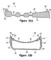
参照图34-35B,其表示出另一个实施例,其中囊30包括接收鞋外底14的侧面部分的多个锯齿状区域63。锯齿状区域63可以位于鞋10的任何区域,但是表现为位于区域15和16的界面和整个脚后跟区域17。换句话说,锯齿状区域63位于侧表面23和24的下部。锯齿状区域63在囊30中凹陷,允许鞋外底14的侧部分向上卷绕(wrap),并上到侧表面23和24中的一个或两个,如图36-37B所示。如图36-37B所示,锯齿状区域63确保鞋外底14与加固结构40的外表面和侧表面23及24的外部平齐。在某些运动鞋中,侧表面23和24的几部分,胜于(rather than)下表面22,与地面接触。具有鞋外底14向上卷绕并上到侧表面23和24中的一者或两者的一个优点是,在侧表面23和24的任何一个接触地面时,鞋外底14限制地面和侧表面23及24之间的滑动。Referring to FIGS. 34-35B , another embodiment is shown in which
尽管,上面论述的锯齿状区域63用于确保鞋外底14与加固结构40的外表面和侧表面23及24的外部平齐,但是鞋外底14可以不与鞋底组件20的所有构造平齐。参照图37C,没有锯齿状区域63,鞋外底14向外延伸超过加固结构40的外表面和侧表面23及24的外部。因此,在某些实施例中,可以没有锯齿状区域63。Although the
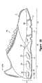
在上面论述的许多实施例中,鞋底组件20延伸通过鞋10的整个纵向长度。但是,上面论述的各种概念,可以应用于其它的仅延伸通过鞋10的纵向长度的一部分鞋底组件20。参照图38,鞋10表现为包括鞋底组件20,延伸通过脚后跟区域17和脚前区域16的一部分。在脚中区域16,鞋底组件20向下渐缩,形成渐缩(tapered)区域64,如图39A和39B的每一图所示,与泡沫元件65连接。更具体地说,上表面21通向下表面22以在渐缩区域减小囊30的厚度。泡沫元件65延伸过渐缩区域并接触上表面21。然而,鞋底组件20位于鞋10的后部区域,泡沫元件65从鞋底组件20向前延伸并通过脚前部分15。在某些实施例中,鞋底组件20可以限制在脚前区域15,而泡沫元件可以向后延伸并通过脚后跟区域17。可选择地,鞋底组件20可以限制于脚中区域16,如此一对泡沫元件延伸分别通过区域15和17。In many of the embodiments discussed above,
如上面所论述,补充层60可以用来控制在外加负载作用下鞋底组件20表面的压缩或变形程度。作为补充层60的一个替代,或除补充层60外,鞋外底14可以可有控制鞋底组件20表面的压缩或变形程度的构造。参照图40A,鞋外底14表现为具有第一区域14A和第二区域14B。第一区域14A主要位于脚后跟区域17,而第二区域14B位于脚前区域15和脚中区域16的每一区域。与第二区域14B相比,第一区域14A可以表现刚性结构以辅助控制在外加负载作用下鞋底组件20表面的压缩或变形程度。另一种构造表示于图40B,其中第一区域14A具有U形设计。As discussed above,
结论in conclusion
前面的论述公开了鞋底组件的各种实施例和鞋底组件的制造方法。通常,鞋底组件包括充有流体的囊和沿囊延伸的加固结构。加固结构粘接到囊的外部,并可以凹进入囊中。在某些实施例中,加固结构沿囊的侧表面和在囊的上、下表面之间延伸。在鞋底组件的制造中,加固结构可以置于模具中,形成囊的聚合物材料可以在模塑工艺中粘接到加固结构。The foregoing discussion discloses various embodiments of sole assemblies and methods of manufacturing sole assemblies. Typically, a sole assembly includes a fluid-filled bladder and a reinforcing structure extending along the bladder. The reinforcing structure is bonded to the exterior of the bladder and can be recessed into the bladder. In some embodiments, the reinforcing structure extends along the side surfaces of the bladder and between the upper and lower surfaces of the bladder. In the manufacture of the sole assembly, the reinforcing structure may be placed in a mold and the polymer material forming the bladder may be bonded to the reinforcing structure during the molding process.
本发明已通过多个实施例和附图公开如上。上述公开的目的,是为涉及本发明的各种特征和概念提供示例,而非限制本发明的范围。所属技术领域的技术人员当可知道,以上描述的各实施例,可以有多种变更或修正,其均不脱离由所附的权利要求所限定的本发明的范围。The invention has been disclosed above by way of several embodiments and figures. The purpose of the above disclosure is to provide examples of the various features and concepts related to the invention, not to limit the scope of the invention. Those skilled in the art should know that various changes or modifications can be made to the above described embodiments without departing from the scope of the present invention defined by the appended claims.
Claims (40)
Translated fromChineseApplications Claiming Priority (2)
| Application Number | Priority Date | Filing Date | Title |
|---|---|---|---|
| US11/251,622 | 2005-10-14 | ||
| US11/251,622US7562469B2 (en) | 2003-12-23 | 2005-10-14 | Footwear with fluid-filled bladder and a reinforcing structure |
Related Child Applications (4)
| Application Number | Title | Priority Date | Filing Date |
|---|---|---|---|
| CN2009101712820ADivisionCN101642307B (en) | 2005-10-14 | 2006-10-04 | Article of footwear having a fluid-filled bladder with a reinforcing structure |
| CN200910171283ADivisionCN101642308A (en) | 2005-10-14 | 2006-10-04 | Article of footwear having a fluid-filled bladder with a reinforcing structure |
| CN200910171284XADivisionCN101642309B (en) | 2005-10-14 | 2006-10-04 | Article of footwear having a fluid-filled bladder with a reinforcing structure |
| CN2009101712854ADivisionCN101642310B (en) | 2005-10-14 | 2006-10-04 | Article of footwear having a fluid-filled bladder with a reinforcing structure |
Publications (2)
| Publication Number | Publication Date |
|---|---|
| CN101287389Atrue CN101287389A (en) | 2008-10-15 |
| CN100579408C CN100579408C (en) | 2010-01-13 |
Family
ID=37734081
Family Applications (5)
| Application Number | Title | Priority Date | Filing Date |
|---|---|---|---|
| CN2009101712820AActiveCN101642307B (en) | 2005-10-14 | 2006-10-04 | Article of footwear having a fluid-filled bladder with a reinforcing structure |
| CN200680038311AActiveCN100579408C (en) | 2005-10-14 | 2006-10-04 | Article of footwear with fluid-filled bladder and reinforcing structure |
| CN200910171284XAActiveCN101642309B (en) | 2005-10-14 | 2006-10-04 | Article of footwear having a fluid-filled bladder with a reinforcing structure |
| CN200910171283APendingCN101642308A (en) | 2005-10-14 | 2006-10-04 | Article of footwear having a fluid-filled bladder with a reinforcing structure |
| CN2009101712854AActiveCN101642310B (en) | 2005-10-14 | 2006-10-04 | Article of footwear having a fluid-filled bladder with a reinforcing structure |
Family Applications Before (1)
| Application Number | Title | Priority Date | Filing Date |
|---|---|---|---|
| CN2009101712820AActiveCN101642307B (en) | 2005-10-14 | 2006-10-04 | Article of footwear having a fluid-filled bladder with a reinforcing structure |
Family Applications After (3)
| Application Number | Title | Priority Date | Filing Date |
|---|---|---|---|
| CN200910171284XAActiveCN101642309B (en) | 2005-10-14 | 2006-10-04 | Article of footwear having a fluid-filled bladder with a reinforcing structure |
| CN200910171283APendingCN101642308A (en) | 2005-10-14 | 2006-10-04 | Article of footwear having a fluid-filled bladder with a reinforcing structure |
| CN2009101712854AActiveCN101642310B (en) | 2005-10-14 | 2006-10-04 | Article of footwear having a fluid-filled bladder with a reinforcing structure |
Country Status (8)
| Country | Link |
|---|---|
| US (6) | US7562469B2 (en) |
| EP (6) | EP1933659B1 (en) |
| JP (5) | JP5198273B2 (en) |
| CN (5) | CN101642307B (en) |
| AU (1) | AU2006303935B2 (en) |
| TW (1) | TWI331906B (en) |
| WO (1) | WO2007047126A1 (en) |
| ZA (1) | ZA200803286B (en) |
Cited By (7)
| Publication number | Priority date | Publication date | Assignee | Title |
|---|---|---|---|---|
| CN104203029A (en)* | 2012-03-23 | 2014-12-10 | 耐克创新有限合伙公司 | Article of footwear having a sole structure with a fluid-filled chamber |
| CN106738565A (en)* | 2010-05-12 | 2017-05-31 | 耐克创新有限合伙公司 | Contouring fluid filled chamber with tension members |
| CN108433243A (en)* | 2010-08-20 | 2018-08-24 | 耐克创新有限合伙公司 | Include the footwear sole construction of trough of belt fluid noggin piece |
| CN111904091A (en)* | 2015-01-29 | 2020-11-10 | 耐克创新有限合伙公司 | Article of footwear with auxetic structure |
| CN112075716A (en)* | 2014-08-06 | 2020-12-15 | 耐克创新有限合伙公司 | Footwear having an upper including a chamber element |
| US10897960B2 (en) | 2010-05-12 | 2021-01-26 | Nike, Inc. | Method of manufacturing a contoured fluid-filled chamber with a tensile member |
| CN115195176A (en)* | 2021-04-13 | 2022-10-18 | 安踏(中国)有限公司 | Shoe forming process and shoe |
Families Citing this family (168)
| Publication number | Priority date | Publication date | Assignee | Title |
|---|---|---|---|---|
| USD911682S1 (en) | 2017-09-14 | 2021-03-02 | Puma SE | Shoe |
| USD911683S1 (en) | 2017-09-14 | 2021-03-02 | Puma SE | Shoe |
| USD910290S1 (en) | 2017-09-14 | 2021-02-16 | Puma SE | Shoe |
| USD953709S1 (en) | 1985-08-29 | 2022-06-07 | Puma SE | Shoe |
| USD855953S1 (en) | 2017-09-14 | 2019-08-13 | Puma SE | Shoe sole element |
| US7634529B2 (en) | 1996-11-29 | 2009-12-15 | Ellis Iii Frampton E | Personal and server computers having microchips with multiple processing units and internal firewalls |
| US7752775B2 (en) | 2000-03-10 | 2010-07-13 | Lyden Robert M | Footwear with removable lasting board and cleats |
| US7707745B2 (en) | 2003-07-16 | 2010-05-04 | Nike, Inc. | Footwear with a sole structure incorporating a lobed fluid-filled chamber |
| US7707744B2 (en) | 2003-07-16 | 2010-05-04 | Nike, Inc. | Footwear with a sole structure incorporating a lobed fluid-filled chamber |
| US7556846B2 (en) | 2003-12-23 | 2009-07-07 | Nike, Inc. | Fluid-filled bladder with a reinforcing structure |
| US8291618B2 (en) | 2004-11-22 | 2012-10-23 | Frampton E. Ellis | Devices with internal flexibility sipes, including siped chambers for footwear |
| US8256147B2 (en) | 2004-11-22 | 2012-09-04 | Frampton E. Eliis | Devices with internal flexibility sipes, including siped chambers for footwear |
| US12290134B2 (en) | 2004-11-22 | 2025-05-06 | Frampton E. Ellis | Footwear or orthotic sole with microprocessor control of a structural or support element with magnetorheological fluid |
| CA2630817C (en) | 2004-11-22 | 2016-10-18 | Frampton E. Ellis | Devices with internal flexibility sipes, including siped chambers for footwear |
| US8904671B2 (en) | 2006-05-25 | 2014-12-09 | Nike, Inc. | Footwear incorporating a tensile element with a deposition layer |
| US8893405B2 (en) | 2006-05-25 | 2014-11-25 | Nike, Inc. | Article of footwear incorporating tensile strands with an elongated cross-sectional shape |
| US7574818B2 (en)* | 2006-05-25 | 2009-08-18 | Nike, Inc. | Article of footwear having an upper with thread structural elements |
| US8312646B2 (en)* | 2006-05-25 | 2012-11-20 | Nike, Inc. | Article of footwear incorporating a tensile element |
| US8418380B2 (en) | 2006-05-25 | 2013-04-16 | Nike, Inc. | Article of footwear having an upper incorporating a tensile strand with a cover layer |
| US7870681B2 (en)* | 2006-05-25 | 2011-01-18 | Nike, Inc. | Article of footwear having an upper with thread structural elements |
| US8312645B2 (en) | 2006-05-25 | 2012-11-20 | Nike, Inc. | Material elements incorporating tensile strands |
| US7685743B2 (en)* | 2006-06-05 | 2010-03-30 | Nike, Inc. | Article of footwear or other foot-receiving device having a fluid-filled bladder with support and reinforcing structures |
| US7810255B2 (en) | 2007-02-06 | 2010-10-12 | Nike, Inc. | Interlocking fluid-filled chambers for an article of footwear |
| US7946058B2 (en)* | 2007-03-21 | 2011-05-24 | Nike, Inc. | Article of footwear having a sole structure with an articulated midsole and outsole |
| US7950169B2 (en) | 2007-05-10 | 2011-05-31 | Nike, Inc. | Contoured fluid-filled chamber |
| EP2200469A2 (en)* | 2007-07-19 | 2010-06-30 | Tomas Schweizer | Shoe with sprung sole |
| US8125796B2 (en) | 2007-11-21 | 2012-02-28 | Frampton E. Ellis | Devices with faraday cages and internal flexibility sipes |
| US8572867B2 (en) | 2008-01-16 | 2013-11-05 | Nike, Inc. | Fluid-filled chamber with a reinforcing element |
| US20090293305A1 (en)* | 2008-05-30 | 2009-12-03 | St Ip, Llc | Full length airbag |
| US8959798B2 (en) | 2008-06-11 | 2015-02-24 | Zurinvest Ag | Shoe sole element |
| EP2132999B1 (en)* | 2008-06-11 | 2015-10-28 | Zurinvest AG | Shoe sole element |
| EP2303049A1 (en)* | 2008-07-14 | 2011-04-06 | Prince Sports, Inc. | An improved sole structure |
| US8122616B2 (en) | 2008-07-25 | 2012-02-28 | Nike, Inc. | Composite element with a polymer connecting layer |
| US9055782B2 (en)* | 2008-10-24 | 2015-06-16 | Kevin McDonnell | Multistructural support system for a sole in a running shoe |
| JP5044529B2 (en)* | 2008-11-13 | 2012-10-10 | アクシュネット カンパニー | Golf shoes |
| US8181364B2 (en)* | 2009-02-06 | 2012-05-22 | Nike, Inc. | Article of footwear with heel cushioning system |
| US20100199406A1 (en)* | 2009-02-06 | 2010-08-12 | Nike, Inc. | Thermoplastic Non-Woven Textile Elements |
| US8388791B2 (en) | 2009-04-07 | 2013-03-05 | Nike, Inc. | Method for molding tensile strand elements |
| US8132340B2 (en)* | 2009-04-07 | 2012-03-13 | Nike, Inc. | Footwear incorporating crossed tensile strand elements |
| US8215033B2 (en)* | 2009-04-16 | 2012-07-10 | Nike, Inc. | Article of footwear for snowboarding |
| USD608998S1 (en)* | 2009-05-06 | 2010-02-02 | Srl, Llc | Pair of infant shoe soles |
| USD608997S1 (en)* | 2009-05-06 | 2010-02-02 | Srl, Llc | Pair of infant shoe soles |
| US8650775B2 (en) | 2009-06-25 | 2014-02-18 | Nike, Inc. | Article of footwear having a sole structure with perimeter and central elements |
| US8266827B2 (en)* | 2009-08-24 | 2012-09-18 | Nike, Inc. | Article of footwear incorporating tensile strands and securing strands |
| USD677451S1 (en)* | 2009-10-12 | 2013-03-12 | Salomon S.A.S. | Outsole portion and midsole portion of a footwear article |
| USD660567S1 (en)* | 2009-10-12 | 2012-05-29 | Salomon S.A.S. | Outsole portion and midsole portion of a footwear article |
| US20110192056A1 (en)* | 2010-02-05 | 2011-08-11 | Deckers Outdoor Corporation | Footwear including a self-adjusting midsole |
| US8316560B2 (en) | 2010-02-15 | 2012-11-27 | Nike, Inc. | Air cushioning outsole window |
| US8991072B2 (en)* | 2010-02-22 | 2015-03-31 | Nike, Inc. | Fluid-filled chamber incorporating a flexible plate |
| US9167867B2 (en)* | 2010-05-13 | 2015-10-27 | Nike, Inc. | Article of footwear with multi-part sole assembly |
| US8973288B2 (en) | 2010-07-30 | 2015-03-10 | Nike, Inc. | Footwear incorporating angled tensile strand elements |
| US8631589B2 (en) | 2010-07-30 | 2014-01-21 | Nike, Inc. | Article of footwear incorporating floating tensile strands |
| US8555415B2 (en) | 2010-08-13 | 2013-10-15 | Nike, Inc. | Apparel incorporating tensile strands |
| US8661717B2 (en) | 2010-08-20 | 2014-03-04 | Nike, Inc. | Article of footwear with slots and method of making |
| US8689467B2 (en) | 2010-08-20 | 2014-04-08 | Nike, Inc. | Sole structure with visual effects |
| US8584377B2 (en)* | 2010-09-14 | 2013-11-19 | Nike, Inc. | Article of footwear with elongated shock absorbing heel system |
| US9144268B2 (en) | 2010-11-02 | 2015-09-29 | Nike, Inc. | Strand-wound bladder |
| EP2638816B1 (en)* | 2010-11-08 | 2017-06-14 | Desarrollo Integral Del Molde, S.L. | Hollow footwear sole and method for manufacturing same |
| US9021720B2 (en)* | 2011-03-16 | 2015-05-05 | Nike, Inc. | Fluid-filled chamber with a tensile member |
| US10010136B2 (en)* | 2011-03-16 | 2018-07-03 | Nike, Inc. | Footwear sole structure incorporating a plurality of chambers |
| US20120311887A1 (en)* | 2011-06-10 | 2012-12-13 | Peter Wong | Therapeutic Shoe Sole and Methods of Manufacturing the Same |
| US9009991B2 (en) | 2011-06-23 | 2015-04-21 | Nike, Inc. | Article of footwear with a cavity viewing system |
| US20130007947A1 (en) | 2011-07-08 | 2013-01-10 | Hurley International, Llc | Water Shorts |
| USD655901S1 (en)* | 2011-07-11 | 2012-03-20 | Skechers U.S.A., Inc. Ii | Shoe outsole and periphery |
| US9113674B2 (en) | 2011-12-15 | 2015-08-25 | Nike, Inc. | Footwear having an upper with forefoot tensile strand elements |
| US11684111B2 (en) | 2012-02-22 | 2023-06-27 | Nike, Inc. | Motorized shoe with gesture control |
| US11071344B2 (en) | 2012-02-22 | 2021-07-27 | Nike, Inc. | Motorized shoe with gesture control |
| US8887410B2 (en) | 2012-02-24 | 2014-11-18 | Nike, Inc. | Articles of footwear with tensile strand elements |
| US8819963B2 (en) | 2012-02-24 | 2014-09-02 | Nike, Inc. | Articles of footwear with tensile strand elements |
| US8925129B2 (en) | 2012-02-24 | 2015-01-06 | Nike, Inc. | Methods of manufacturing articles of footwear with tensile strand elements |
| US8919015B2 (en) | 2012-03-08 | 2014-12-30 | Nike, Inc. | Article of footwear having a sole structure with a flexible groove |
| USD702430S1 (en)* | 2012-05-10 | 2014-04-15 | Columbia Sportswear North America, Inc. | Footwear |
| US9179739B2 (en) | 2012-06-21 | 2015-11-10 | Nike, Inc. | Footwear incorporating looped tensile strand elements |
| US10631593B2 (en)* | 2012-08-21 | 2020-04-28 | Levi J. Patton | Fluid-filled chamber with a stabilization structure |
| CN104822284B (en) | 2012-08-31 | 2016-10-19 | 耐克创新有限合伙公司 | Motorized tensioning system with sensor |
| WO2014036371A1 (en) | 2012-08-31 | 2014-03-06 | Nike International Ltd. | Motorized tensioning system |
| US9572398B2 (en)* | 2012-10-26 | 2017-02-21 | Nike, Inc. | Sole structure with alternating spring and damping layers |
| US9861160B2 (en) | 2012-11-30 | 2018-01-09 | Nike, Inc. | Article of footwear incorporating a knitted component |
| US9380832B2 (en) | 2012-12-20 | 2016-07-05 | Nike, Inc. | Article of footwear with fluid-filled chamber lacking an inflation channel and method for making the same |
| US9259049B2 (en) | 2013-01-22 | 2016-02-16 | Nike, Inc. | Ultralightweight adaptive heel member |
| US10806214B2 (en)* | 2013-03-08 | 2020-10-20 | Nike, Inc. | Footwear fluid-filled chamber having central tensile feature |
| US9386820B2 (en) | 2013-03-15 | 2016-07-12 | Rikco International Llc | Pressure relief system for footwear |
| USD733413S1 (en)* | 2013-05-14 | 2015-07-07 | Columbia Sportswear North America, Inc. | Footwear |
| USD733411S1 (en)* | 2013-05-14 | 2015-07-07 | Columbia Sportswear North America, Inc. | Footwear |
| USD734006S1 (en)* | 2013-05-14 | 2015-07-14 | Columbia Sportswear North America, Inc. | Footwear |
| USD733412S1 (en)* | 2013-05-14 | 2015-07-07 | Columbia Sportswear North America, Inc. | Footwear |
| WO2015017446A1 (en)* | 2013-08-02 | 2015-02-05 | Skydex Technologies, Inc | Differing void cell matrices for sole support |
| JP5968552B2 (en)* | 2013-10-21 | 2016-08-10 | 株式会社アシックス | Cushion structure on the side of the sole and shoes to which this is applied |
| US20150208760A1 (en)* | 2014-01-24 | 2015-07-30 | Tung-Cheng Chen | Sole for rehabilitation footwear |
| US9326566B2 (en) | 2014-04-15 | 2016-05-03 | Nike, Inc. | Footwear having coverable motorized adjustment system |
| US10092065B2 (en) | 2014-04-15 | 2018-10-09 | Nike, Inc. | Footwear having motorized adjustment system and removable midsole |
| US9629418B2 (en) | 2014-04-15 | 2017-04-25 | Nike, Inc. | Footwear having motorized adjustment system and elastic upper |
| USD756085S1 (en)* | 2014-05-15 | 2016-05-17 | Columbia Sportswear North America, Inc. | Footwear |
| USD754956S1 (en)* | 2014-05-15 | 2016-05-03 | Columbia Sportswear North America, Inc. | Footwear |
| US9687044B2 (en)* | 2014-07-24 | 2017-06-27 | Nike, Inc. | Footwear with sole structure incorporating lobed fluid-filled chamber with protruding end wall portions |
| USD723773S1 (en)* | 2014-08-04 | 2015-03-10 | Skechers U.S.A., Inc. Ii | Shoe outsole periphery |
| US10342291B2 (en) | 2014-08-25 | 2019-07-09 | Nike, Inc. | Article with sole structure having multiple components |
| US10064448B2 (en)* | 2014-08-27 | 2018-09-04 | Nike, Inc. | Auxetic sole with upper cabling |
| USD767263S1 (en)* | 2015-02-17 | 2016-09-27 | Austin J. Reiser | Fillable shoe sole |
| EP3552509B1 (en) | 2015-04-08 | 2021-03-17 | NIKE Innovate C.V. | Article with a cushioning assembly having inner and outer bladder elements and a reinforcement element and method of manufacturing an article |
| CN107427100B (en)* | 2015-04-08 | 2020-06-30 | 耐克创新有限合伙公司 | Article having a cushioning assembly including an inner bladder element and an outer bladder element with interfitting features and method of making the article |
| EP3285607B1 (en) | 2015-04-21 | 2020-05-06 | Nike Innovate C.V. | Bladder element formed from three sheets and method of manufacturing a bladder element |
| EP3285608B1 (en) | 2015-04-24 | 2019-05-22 | Nike Innovate C.V. | Footwear sole structure having bladder with integrated outsole |
| USD770152S1 (en)* | 2015-05-15 | 2016-11-01 | Nike, Inc. | Shoe outsole |
| DE102015212099B4 (en)* | 2015-06-29 | 2022-01-27 | Adidas Ag | soles for sports shoes |
| US9615622B2 (en)* | 2015-09-02 | 2017-04-11 | Nike, Inc. | Footwear with rimmed sole structure |
| EP3788901B1 (en)* | 2015-11-03 | 2023-03-22 | Nike Innovate C.V. | Article of footwear including a bladder element having a cushioning component with a single central opening and a cushioning component with multiple connecting features and method of manufacturing |
| GB2544555B (en)* | 2015-11-23 | 2019-10-23 | Fitflop Ltd | An item of footwear |
| USD773161S1 (en)* | 2016-01-28 | 2016-12-06 | Skechers U.S.A., Inc. Ii | Shoe midsole periphery |
| AU2017235417B2 (en) | 2016-03-15 | 2019-06-27 | Nike Innovate C.V. | Sole structure for article of footwear |
| KR102333507B1 (en)* | 2016-03-15 | 2021-12-01 | 나이키 이노베이트 씨.브이. | Sole structure for article of footwear |
| CN114403546B (en)* | 2016-03-15 | 2025-02-25 | 耐克创新有限合伙公司 | Article of footwear having first and second outsole components and method of making the same |
| US11224263B2 (en)* | 2016-06-23 | 2022-01-18 | Darco Internationa I;, Inc. | Medical shoe having a plurality of outsole projections |
| WO2017222526A1 (en) | 2016-06-23 | 2017-12-28 | Darco International, Inc. | Medical shoe having multi-density overmolding |
| WO2018098463A1 (en)* | 2016-11-28 | 2018-05-31 | The Board Of Regents Of The University Of Texas System | Dual-layer insole apparatuses for diabetic foot lesion prevention and related methods |
| USD850766S1 (en) | 2017-01-17 | 2019-06-11 | Puma SE | Shoe sole element |
| US10575588B2 (en) | 2017-03-27 | 2020-03-03 | Adidas Ag | Footwear midsole with warped lattice structure and method of making the same |
| US10932521B2 (en) | 2017-03-27 | 2021-03-02 | Adidas Ag | Footwear midsole with warped lattice structure and method of making the same |
| KR102326973B1 (en) | 2017-05-23 | 2021-11-16 | 나이키 이노베이트 씨.브이. | Midsole with graded response |
| CN110662442B (en) | 2017-05-23 | 2021-08-24 | 耐克创新有限合伙公司 | Midsole system with graded response |
| KR102360537B1 (en) | 2017-05-23 | 2022-02-09 | 나이키 이노베이트 씨.브이. | Domed midsole with staged compressive stiffness |
| CN110913715B (en) | 2017-08-11 | 2022-05-27 | 彪马欧洲股份公司 | Method for producing shoes |
| USD975417S1 (en) | 2017-09-14 | 2023-01-17 | Puma SE | Shoe |
| US11452334B2 (en) | 2018-01-31 | 2022-09-27 | Nike, Inc. | Airbag for article of footwear |
| US10149513B1 (en) | 2018-01-31 | 2018-12-11 | Nike, Inc. | Sole structure for article of footwear |
| US11832684B2 (en) | 2018-04-27 | 2023-12-05 | Puma SE | Shoe, in particular a sports shoe |
| JP6975351B2 (en) | 2018-05-08 | 2021-12-01 | プーマ エス イーPuma Se | Sole of shoes, especially sports shoes |
| CN112135727B (en) | 2018-05-08 | 2023-02-03 | 彪马欧洲股份公司 | Method for producing soles for shoes, in particular sports shoes |
| US11026476B2 (en)* | 2018-07-17 | 2021-06-08 | Nike, Inc. | Airbag for article of footwear |
| US10524540B1 (en) | 2018-07-17 | 2020-01-07 | Nike, Inc. | Airbag for article of footwear |
| JP7157880B2 (en) | 2018-12-18 | 2022-10-20 | プーマ エス イー | Shoes, especially athletic shoes, and methods of making same |
| US12171300B2 (en)* | 2019-03-28 | 2024-12-24 | Nike, Inc. | Sole structure of an article of footwear |
| USD876770S1 (en)* | 2019-04-19 | 2020-03-03 | Nike, Inc. | Shoe |
| USD876768S1 (en)* | 2019-04-19 | 2020-03-03 | Nike, Inc. | Shoe |
| USD900441S1 (en)* | 2019-04-19 | 2020-11-03 | Nike, Inc. | Shoe |
| USD909726S1 (en)* | 2019-04-26 | 2021-02-09 | Foot Care Store Inc. | Footwear sole |
| USD878019S1 (en)* | 2019-05-17 | 2020-03-17 | Nike, Inc. | Shoe |
| USD901142S1 (en)* | 2019-05-17 | 2020-11-10 | Nike, Inc. | Shoe |
| US11490679B2 (en)* | 2019-09-25 | 2022-11-08 | Nike, Inc. | Foot support components for articles of footwear |
| USD948184S1 (en)* | 2019-10-25 | 2022-04-12 | U-Invest S.R.L. | Safety shoe |
| US12102171B2 (en)* | 2019-11-08 | 2024-10-01 | Skechers U.S.A., Inc. Ii | Supporting member for footwear activity economy |
| US11638463B2 (en)* | 2019-11-19 | 2023-05-02 | Nike, Inc. | Sole structure for article of footwear |
| US11666117B2 (en)* | 2019-11-19 | 2023-06-06 | Nike, Inc. | Sole structure for article of footwear |
| USD893845S1 (en)* | 2020-04-03 | 2020-08-25 | Jionglin Chen | Shoe sole |
| USD944504S1 (en) | 2020-04-27 | 2022-03-01 | Puma SE | Shoe |
| EP3928970A1 (en)* | 2020-06-26 | 2021-12-29 | Ecco Sko A/S | An article of footwear |
| US11786008B2 (en) | 2020-10-07 | 2023-10-17 | Adidas Ag | Footwear with 3-D printed midsole |
| USD1022425S1 (en) | 2020-10-07 | 2024-04-16 | Adidas Ag | Shoe |
| US12082646B2 (en) | 2020-10-13 | 2024-09-10 | Adidas Ag | Footwear and footwear components having a mesh component |
| US11589647B2 (en) | 2020-10-13 | 2023-02-28 | Adidas Ag | Footwear midsole with anisotropic mesh and methods of making the same |
| USD980594S1 (en) | 2020-10-13 | 2023-03-14 | Adidas Ag | Shoe |
| US11992084B2 (en) | 2020-10-13 | 2024-05-28 | Adidas Ag | Footwear midsole with 3-D printed mesh having an anisotropic structure and methods of making the same |
| USD980595S1 (en) | 2020-10-13 | 2023-03-14 | Adidas Ag | Shoe |
| CN112515290A (en)* | 2020-12-02 | 2021-03-19 | 福鼎市尚尚品服饰有限公司 | Shock-absorbing shoe pad and manufacturing method thereof |
| USD955710S1 (en)* | 2021-03-02 | 2022-06-28 | Skechers U.S.A., Inc. Ii | Shoe midsole periphery |
| USD948848S1 (en)* | 2021-03-26 | 2022-04-19 | Converse Inc. | Shoe |
| USD948847S1 (en)* | 2021-03-26 | 2022-04-19 | Converse Inc. | Shoe |
| USD946253S1 (en)* | 2021-04-01 | 2022-03-22 | Skechers U.S.A., Inc. Ii | Shoe midsole periphery |
| USD1025564S1 (en) | 2021-05-05 | 2024-05-07 | Converse Inc. | Shoe |
| US12109775B2 (en) | 2021-12-22 | 2024-10-08 | Puma SE | Method for producing a sole of a shoe |
| USD1012450S1 (en)* | 2022-01-21 | 2024-01-30 | Ecco Sko A/S | Footwear |
| JP2024124738A (en)* | 2023-03-03 | 2024-09-13 | 株式会社アシックス | Soles and shoes |
| US20240306768A1 (en)* | 2023-03-15 | 2024-09-19 | Nike, Inc. | Article of footwear including a sole structure |
| USD1076369S1 (en)* | 2023-12-22 | 2025-05-27 | Nike, Inc. | Shoe |
| US12414602B2 (en) | 2023-12-29 | 2025-09-16 | Adidas Ag | Additively manufactured footwear soles |
| USD1092030S1 (en) | 2024-01-05 | 2025-09-09 | Adidas Ag | Shoe |
| USD1093836S1 (en)* | 2024-09-17 | 2025-09-23 | Skechers U.S.A., Inc. Ii | Shoe sole |
| USD1094985S1 (en)* | 2024-09-17 | 2025-09-30 | Skechers U.S.A., Inc. Ii | Outsole bottom |
Family Cites Families (225)
| Publication number | Priority date | Publication date | Assignee | Title |
|---|---|---|---|---|
| CA727582A (en) | 1966-02-08 | E. Jackson Albert | Inflatable bolster | |
| US1323610A (en) | 1919-12-02 | price | ||
| US767211A (en) | 1903-06-04 | 1904-08-09 | Nancy J Dobbins | Egg-preserving compound. |
| US900867A (en) | 1907-06-24 | 1908-10-13 | Benjamin N B Miller | Cushion for footwear. |
| US1069001A (en) | 1913-01-14 | 1913-07-29 | William H Guy | Cushioned sole and heel for shoes. |
| US1240153A (en) | 1916-01-07 | 1917-09-11 | Keene Shock Absorber Company | Pneumatic cushion for shoes. |
| US1304915A (en) | 1918-07-31 | 1919-05-27 | Burton A Spinney | Pneumatic insole. |
| US1584034A (en) | 1922-06-05 | 1926-05-11 | Klotz Alfred | Pneumatic insertion for shoes |
| US1514468A (en) | 1922-08-02 | 1924-11-04 | John P W Schopf | Arch cushion |
| GB233387A (en) | 1924-01-04 | 1925-05-04 | Thomas Francis Farrimond | Improvements in or relating to cushioning devices for use inside footwear |
| US1625582A (en) | 1924-11-10 | 1927-04-19 | Airubber Corp | Flexible hollow articles and method of making the same |
| US1793703A (en) | 1925-02-27 | 1931-02-24 | Krichbaum Ora | Rubber article |
| US1869257A (en) | 1929-12-10 | 1932-07-26 | Hitzler Theodor | Insole |
| US1916483A (en) | 1930-03-14 | 1933-07-04 | Krichbaum Ora | Inflatable article |
| US1970803A (en) | 1932-10-03 | 1934-08-21 | Johnson John Herbert | Method of making an inflatable rubber structure |
| US2080469A (en) | 1933-05-17 | 1937-05-18 | Levi L Gilbert | Pneumatic foot support |
| US2004906A (en) | 1934-03-05 | 1935-06-11 | Joseph Farese | Pneumatic shoe |
| US2086389A (en) | 1936-09-24 | 1937-07-06 | Pearson Susan Clare | Inflated arch support and ventilated heel cushion |
| US2269342A (en) | 1938-05-31 | 1942-01-06 | K & W Rubber Corp | Inflatable rubber goods |
| US2365807A (en) | 1943-04-17 | 1944-12-26 | Emmanuel M Dialynas | Pneumatic or cushion arch support for shoes |
| US2488382A (en) | 1946-06-07 | 1949-11-15 | Whitman W Davis | Pneumatic foot support |
| US2546827A (en) | 1948-10-02 | 1951-03-27 | Lavinthal Albert | Arch supporting device |
| US2600239A (en) | 1949-11-01 | 1952-06-10 | Levi L Gilbert | Pneumatic insole |
| US2703770A (en) | 1952-04-15 | 1955-03-08 | Melzer Jean | Manufacture of flat inflatable objects |
| US2748401A (en) | 1952-06-30 | 1956-06-05 | Hedwin Corp | Extruded flexible and hollow articles and method of making same |
| US2645865A (en) | 1952-07-25 | 1953-07-21 | Edward W Town | Cushioning insole for shoes |
| US2677906A (en) | 1952-08-14 | 1954-05-11 | Reed Arnold | Cushioned inner sole for shoes and meth od of making the same |
| AT181938B (en) | 1953-03-02 | 1955-05-10 | Leopold Dworak | Sitting area |
| US2762134A (en) | 1954-07-30 | 1956-09-11 | Edward W Town | Cushioning insoles for shoes |
| AT200963B (en) | 1955-11-19 | 1958-12-10 | Adolf Dr Schuetz | Shoe insert |
| FR1195549A (en) | 1958-05-02 | 1959-11-18 | Air mattress | |
| US3048514A (en) | 1958-09-17 | 1962-08-07 | Us Rubber Co | Methods and apparatus for making inflatable cushions |
| US3030640A (en) | 1960-01-13 | 1962-04-24 | Air Pillow & Cushions Inc | Inflated articles |
| US3208898A (en) | 1960-03-09 | 1965-09-28 | Sealed Air Corp | Apparatus for embossing and laminating materials |
| US3121430A (en) | 1960-05-10 | 1964-02-18 | Edwin L O'reilly | Inflatable insole with self-fitting arch support |
| US3120712A (en) | 1961-08-30 | 1964-02-11 | Menken Lester Lambert | Shoe construction |
| US3160963A (en) | 1963-06-07 | 1964-12-15 | Aaskov Helmer | Air-filled sandal |
| US3366525A (en) | 1964-02-06 | 1968-01-30 | Hexcel Corp | Method of making thermoplastic honeycomb |
| US3204678A (en) | 1964-02-14 | 1965-09-07 | Gurdon S Worcester | Beach bag |
| FR1406610A (en) | 1964-06-10 | 1965-07-23 | Perfected shoe | |
| US3335045A (en) | 1964-06-15 | 1967-08-08 | Post Louis | Method for making an inflatable article |
| FR1419847A (en) | 1964-10-22 | 1965-12-03 | Pennel & Flipo Ets | Inflatable item, especially air mattress |
| US3284264A (en) | 1965-03-01 | 1966-11-08 | Gerald J O'rourke | Method of making a bellows structure of thermosetting material |
| US3251076A (en) | 1965-03-19 | 1966-05-17 | Daniel M Burke | Impact absorbing mat |
| US3469576A (en) | 1966-10-05 | 1969-09-30 | Henry M Smith | Footwear |
| US3568227A (en) | 1968-04-10 | 1971-03-09 | Philips Maine Corp | Inflatable cushion and apparatus for making same |
| US3589037A (en) | 1969-05-27 | 1971-06-29 | John P Gallagher | Foot cushioning support member |
| US3608215A (en) | 1969-06-14 | 1971-09-28 | Tatsuo Fukuoka | Footwear |
| US3685176A (en) | 1970-07-02 | 1972-08-22 | Marion F Rudy | Inflatable article of footwear |
| US3758964A (en) | 1971-10-25 | 1973-09-18 | Onitsuka Co Ltd | Sports shoe |
| US3765422A (en) | 1971-12-27 | 1973-10-16 | H Smith | Fluid cushion podiatric insole |
| US4129951A (en) | 1976-04-20 | 1978-12-19 | Charles Petrosky | Air cushion shoe base |
| US4017931A (en) | 1976-05-20 | 1977-04-19 | The Jonathan-Alan Corporation | Liquid filled insoles |
| US4054960A (en) | 1976-06-25 | 1977-10-25 | Pettit John E | Inflatable body support cushion, particularly to support a woman during pregnancy |
| US4183156A (en)* | 1977-01-14 | 1980-01-15 | Robert C. Bogert | Insole construction for articles of footwear |
| US4115934A (en) | 1977-02-11 | 1978-09-26 | Hall John M | Liquid shoe innersole |
| US4217705A (en) | 1977-03-04 | 1980-08-19 | Donzis Byron A | Self-contained fluid pressure foot support device |
| US4123855A (en) | 1977-08-10 | 1978-11-07 | Thedford Shirley C | Fluid filled insole |
| FR2404413A1 (en) | 1977-09-28 | 1979-04-27 | Seban Norbert | Inflatable mattresses etc. with internal and external ties - for modular assembly of pneumatic panels of controlled depth |
| US4287250A (en) | 1977-10-20 | 1981-09-01 | Robert C. Bogert | Elastomeric cushioning devices for products and objects |
| FR2407008A1 (en) | 1977-10-28 | 1979-05-25 | Bataille Jean Roger | DYNAMIC FOOT AND LEG TIMING PACKAGE IN A RIGID PACKAGE |
| US4167795A (en) | 1978-04-14 | 1979-09-18 | Liberty Vinyl Corporation | Motion suppressing fluid mattress |
| US4340626A (en) | 1978-05-05 | 1982-07-20 | Rudy Marion F | Diffusion pumping apparatus self-inflating device |
| JPS5531482A (en)* | 1978-05-05 | 1980-03-05 | Rudy Marion F | Selffexpansion device |
| US4187620A (en) | 1978-06-15 | 1980-02-12 | Selner Allen J | Biomechanical shoe |
| US4219945B1 (en) | 1978-06-26 | 1993-10-19 | Robert C. Bogert | Footwear |
| US4305212A (en) | 1978-09-08 | 1981-12-15 | Coomer Sven O | Orthotically dynamic footwear |
| US4297797A (en) | 1978-12-18 | 1981-11-03 | Meyers Stuart R | Therapeutic shoe |
| US4328599A (en) | 1979-06-27 | 1982-05-11 | Mollura Carlos A | Firmness regulated waterbed mattress |
| US4292702A (en) | 1979-07-20 | 1981-10-06 | Phillips Raymond M | Surge dampened water bed mattress |
| US4271606A (en) | 1979-10-15 | 1981-06-09 | Robert C. Bogert | Shoes with studded soles |
| US4358902A (en) | 1980-04-02 | 1982-11-16 | Cole George S | Thrust producing shoe sole and heel |
| FR2483321A1 (en) | 1980-06-03 | 1981-12-04 | Taurus Gumiipari Vallalat | Inflatable mattresses supported by low internal pressure - have intermittently bonded interlayer |
| SE8102124L (en) | 1981-04-02 | 1982-10-03 | Lars Gustaf Birger Peterson | SOLE |
| DE3147589A1 (en) | 1981-12-01 | 1983-06-09 | Konsumex Külkereskedelmi Vállalat, 1146 Budapest | "SELF-ADJUSTING ORTHOPEDIC SHOE INSERT AND / OR FLAT FOOT INSERT" |
| US4483030A (en) | 1982-05-03 | 1984-11-20 | Medisearch Pr, Inc. | Air pad |
| FR2526643A1 (en) | 1982-05-14 | 1983-11-18 | Certran | METHOD FOR MAKING PUSHED FOOTWEAR ARTICLES AT DIFFERENT PRESSURES IN THEIR DIFFERENT ZONES AND DRAFT FOR ITS IMPLEMENTATION |
| US4486964A (en) | 1982-06-18 | 1984-12-11 | Rudy Marion F | Spring moderator for articles of footwear |
| US4506460A (en) | 1982-06-18 | 1985-03-26 | Rudy Marion F | Spring moderator for articles of footwear |
| DE3234086A1 (en) | 1982-09-14 | 1984-03-15 | Berta Frey & Söhne Schuhfabrik, 8330 Eggenfelden | Motorcycle boot |
| US4446634A (en) | 1982-09-28 | 1984-05-08 | Johnson Paul H | Footwear having improved shock absorption |
| US4547919A (en) | 1983-02-17 | 1985-10-22 | Cheng Chung Wang | Inflatable article with reforming and reinforcing structure |
| US4662087A (en) | 1984-02-21 | 1987-05-05 | Force Distribution, Inc. | Hydraulic fit system for footwear |
| US5104477A (en) | 1984-10-17 | 1992-04-14 | Bridgestone/Firestone, Inc. | Elastomeric structures having controlled surface release characteristics |
| US4670995A (en) | 1985-03-13 | 1987-06-09 | Huang Ing Chung | Air cushion shoe sole |
| JPS61226084A (en) | 1985-03-30 | 1986-10-07 | 株式会社タチエス | Vehicle seat skin member and its manufacturing method |
| US4920591A (en) | 1985-07-16 | 1990-05-01 | Hiroshi Sekido | Air support for chair and method for manufacturing chair utilizing the air support |
| AU564808B2 (en) | 1985-08-23 | 1987-08-27 | Huang, I-C. | Manufacturing shoe soles with an air cushion |
| US4698864A (en) | 1985-11-25 | 1987-10-13 | Graebe Robert H | Cellular cushion |
| US4803029A (en) | 1986-01-28 | 1989-02-07 | Pmt Corporation | Process for manufacturing an expandable member |
| US5158767A (en) | 1986-08-29 | 1992-10-27 | Reebok International Ltd. | Athletic shoe having inflatable bladder |
| US4744157A (en) | 1986-10-03 | 1988-05-17 | Dubner Benjamin B | Custom molding of footgear |
| FR2614510A1 (en) | 1987-04-30 | 1988-11-04 | Technisynthese Sarl | Sole incorporating a pump for ventilating the shoe |
| US4845338A (en) | 1988-04-04 | 1989-07-04 | Nikola Lakic | Inflatable boot liner with electrical generator and heater |
| US5846063A (en) | 1987-05-26 | 1998-12-08 | Nikola Lakic | Miniature universal pump and valve for inflatable liners |
| US5025575A (en) | 1989-03-14 | 1991-06-25 | Nikola Lakic | Inflatable sole lining for shoes and boots |
| US4823482A (en) | 1987-09-04 | 1989-04-25 | Nikola Lakic | Inner shoe with heat engine for boot or shoe |
| US4782602A (en) | 1987-05-26 | 1988-11-08 | Nikola Lakic | Shoe with foot warmer including an electrical generator |
| US4991317A (en) | 1987-05-26 | 1991-02-12 | Nikola Lakic | Inflatable sole lining for shoes and boots |
| US5199191A (en) | 1987-05-29 | 1993-04-06 | Armenak Moumdjian | Athletic shoe with inflatable mobile inner sole |
| IT1204662B (en) | 1987-05-29 | 1989-03-10 | Armenak Moumdjian | PNEUMATIC CHAMBER INSOLE FOR FOOTWEAR, MOLD AND FORMING METHOD RELATED |
| US4779359A (en) | 1987-07-30 | 1988-10-25 | Famolare, Inc. | Shoe construction with air cushioning |
| US4817304A (en) | 1987-08-31 | 1989-04-04 | Nike, Inc. And Nike International Ltd. | Footwear with adjustable viscoelastic unit |
| US4874640A (en) | 1987-09-21 | 1989-10-17 | Donzis Byron A | Impact absorbing composites and their production |
| US5235715A (en) | 1987-09-21 | 1993-08-17 | Donzis Byron A | Impact asborbing composites and their production |
| US5046267A (en) | 1987-11-06 | 1991-09-10 | Nike, Inc. | Athletic shoe with pronation control device |
| MY106949A (en) | 1988-02-05 | 1995-08-30 | Rudy Marion F | Pressurizable envelope and method |
| US5083361A (en) | 1988-02-05 | 1992-01-28 | Robert C. Bogert | Pressurizable envelope and method |
| US4906502A (en) | 1988-02-05 | 1990-03-06 | Robert C. Bogert | Pressurizable envelope and method |
| CA1338369C (en) | 1988-02-24 | 1996-06-11 | Jean-Pierre Vermeulen | Shock absorbing system for footwear application |
| US4912861A (en) | 1988-04-11 | 1990-04-03 | Huang Ing Chung | Removable pressure-adjustable shock-absorbing cushion device with an inflation pump for sports goods |
| IT8884115A0 (en) | 1988-04-18 | 1988-04-18 | Marc Sadler Design Di Marc Sad | FOOTWEAR WITH SOLE EQUIPPED WITH SHOCK ABSORBER DEVICE. |
| US4864738A (en) | 1988-07-19 | 1989-09-12 | Zvi Horovitz | Sole construction for footwear |
| US4972611A (en) | 1988-08-15 | 1990-11-27 | Ryka, Inc. | Shoe construction with resilient, absorption and visual components based on spherical pocket inclusions |
| US4891855A (en) | 1988-11-14 | 1990-01-09 | Team Worldwide Corporation | Inflatable suntanner with speedy and homogeneous suntan effect |
| FR2639537B1 (en) | 1988-11-15 | 1993-08-13 | Epinoy Ind | SEAT CUSHION, MEDICAL OR COMFORT |
| US5042176A (en) | 1989-01-19 | 1991-08-27 | Robert C. Bogert | Load carrying cushioning device with improved barrier material for control of diffusion pumping |
| US4936029A (en) | 1989-01-19 | 1990-06-26 | R. C. Bogert | Load carrying cushioning device with improved barrier material for control of diffusion pumping |
| US4999932A (en) | 1989-02-14 | 1991-03-19 | Royce Medical Company | Variable support shoe |
| US5253435A (en) | 1989-03-17 | 1993-10-19 | Nike, Inc. | Pressure-adjustable shoe bladder assembly |
| US5257470A (en) | 1989-03-17 | 1993-11-02 | Nike, Inc. | Shoe bladder system |
| US5014449A (en) | 1989-09-22 | 1991-05-14 | Avia Group International, Inc. | Shoe sole construction |
| CN1053884A (en) | 1990-02-09 | 1991-08-21 | 海·克雷默 | Article of footwear with an improved midsole |
| US5060401A (en) | 1990-02-12 | 1991-10-29 | Whatley Ian H | Footwear cushinoning spring |
| US5005299A (en) | 1990-02-12 | 1991-04-09 | Whatley Ian H | Shock absorbing outsole for footwear |
| JPH05503865A (en) | 1990-02-16 | 1993-06-24 | トレトルン アクティエボラーグ | stability shoe device |
| US5238231A (en) | 1990-02-26 | 1993-08-24 | Huang Ing Chung | Shock-absorbing units interconnectable to form shock-absorbing structures |
| US5669161A (en) | 1990-02-26 | 1997-09-23 | Huang; Ing-Jing | Shock-absorbing cushion |
| US6428865B1 (en) | 1990-02-26 | 2002-08-06 | Ing-Chung Huang | Shock-absorbing cushion with a multi-holed and/or grooved surface |
| US5245766A (en) | 1990-03-30 | 1993-09-21 | Nike, Inc. | Improved cushioned shoe sole construction |
| US5224277A (en) | 1990-05-22 | 1993-07-06 | Kim Sang Do | Footwear sole providing ventilation, shock absorption and fashion |
| US5044030A (en) | 1990-06-06 | 1991-09-03 | Fabrico Manufacturing Corporation | Multiple layer fluid-containing cushion |
| US5022109A (en) | 1990-06-11 | 1991-06-11 | Dielectrics Industries | Inflatable bladder |
| DE4035416A1 (en) | 1990-11-07 | 1992-05-14 | Adidas Ag | SHOE BASE, ESPECIALLY FOR SPORTSHOES |
| DE4114551C2 (en) | 1990-11-07 | 2000-07-27 | Adidas Ag | Shoe bottom, in particular for sports shoes |
| US5155927A (en) | 1991-02-20 | 1992-10-20 | Asics Corporation | Shoe comprising liquid cushioning element |
| US5258421A (en) | 1991-03-20 | 1993-11-02 | Hydromer, Inc. | Method for making tacky, hydrophilic gel dressings |
| US5179792A (en) | 1991-04-05 | 1993-01-19 | Brantingham Charles R | Shoe sole with randomly varying support pattern |
| US5193246A (en) | 1991-07-23 | 1993-03-16 | Huang Ing Chung | Air cushion grip with a cubic supporting structure and shock-absorbing function |
| US5355552A (en) | 1991-07-23 | 1994-10-18 | Huang Ing Chung | Air cushion grip with a cubic supporting structure and shock-absorbing function |
| US5353523A (en) | 1991-08-02 | 1994-10-11 | Nike, Inc. | Shoe with an improved midsole |
| US5572804A (en) | 1991-09-26 | 1996-11-12 | Retama Technology Corp. | Shoe sole component and shoe sole component construction method |
| KR100224293B1 (en) | 1991-09-26 | 1999-10-15 | 제이. 스카자 조셉 | Sole member |
| TW214511B (en) | 1991-11-01 | 1993-10-11 | Nike International Ltd | |
| US5406719A (en) | 1991-11-01 | 1995-04-18 | Nike, Inc. | Shoe having adjustable cushioning system |
| US5598645A (en) | 1992-01-02 | 1997-02-04 | Adidas Ab | Shoe sole, in particular for sports shoes, with inflatable tube elements |
| US5279051A (en) | 1992-01-31 | 1994-01-18 | Ian Whatley | Footwear cushioning spring |
| US5440826A (en) | 1992-04-08 | 1995-08-15 | Whatley; Ian H. | Shock absorbing outsole for footwear |
| US5228156A (en) | 1992-05-08 | 1993-07-20 | John Wang | Fluid operated device |
| KR970008896B1 (en) | 1992-07-27 | 1997-05-30 | Converse Inc | Reaction energy device for imparting to shoes cushioning action, ankle support, stability and fitting feel of a custom |
| US5224278A (en) | 1992-09-18 | 1993-07-06 | Jeon Pil D | Midsole having a shock absorbing air bag |
| US5353549A (en) | 1992-11-06 | 1994-10-11 | The Standard Products Company | Molded weatherstrip and method |
| US5335382A (en) | 1992-11-23 | 1994-08-09 | Huang Yin Jun | Inflatable cushion device |
| US5367791A (en) | 1993-02-04 | 1994-11-29 | Asahi, Inc. | Shoe sole |
| TW234081B (en) | 1993-02-04 | 1994-11-11 | Converse Inc | |
| US5625964A (en) | 1993-03-29 | 1997-05-06 | Nike, Inc. | Athletic shoe with rearfoot strike zone |
| US5425184A (en) | 1993-03-29 | 1995-06-20 | Nike, Inc. | Athletic shoe with rearfoot strike zone |
| US6258421B1 (en) | 1993-07-23 | 2001-07-10 | Nike, Inc. | Bladder and method of making the same |
| US5353459A (en)* | 1993-09-01 | 1994-10-11 | Nike, Inc. | Method for inflating a bladder |
| US5592706A (en) | 1993-11-09 | 1997-01-14 | Teksource, Lc | Cushioning device formed from separate reshapable cells |
| US6453577B1 (en)* | 1996-02-09 | 2002-09-24 | Reebok International Ltd. | Support and cushioning system for an article of footwear |
| CA2181998C (en) | 1994-01-26 | 2003-05-13 | Paul E. Litchfield | Cushioning member for an article of footwear |
| US5771606A (en) | 1994-10-14 | 1998-06-30 | Reebok International Ltd. | Support and cushioning system for an article of footwear |
| US5595004A (en) | 1994-03-30 | 1997-01-21 | Nike, Inc. | Shoe sole including a peripherally-disposed cushioning bladder |
| US5465507A (en)* | 1994-04-13 | 1995-11-14 | Osage Footwear, Inc. | Integral sole with footprint embossing |
| US5952065A (en)* | 1994-08-31 | 1999-09-14 | Nike, Inc. | Cushioning device with improved flexible barrier membrane |
| TW286269B (en) | 1994-11-28 | 1996-09-21 | Marion Frank Rudy | |
| AU4365396A (en) | 1994-12-02 | 1996-06-19 | Nike International Ltd. | Cushioning device for a footwear sole and method for making the same |
| US5753061A (en) | 1995-06-05 | 1998-05-19 | Robert C. Bogert | Multi-celled cushion and method of its manufacture |
| US5686167A (en) | 1995-06-05 | 1997-11-11 | Robert C. Bogert | Fatigue resistant fluid containing cushioning device for articles of footwear |
| DE69633198T2 (en)* | 1995-06-07 | 2005-09-08 | Nike International Ltd., Beaverton | BOTTLED, LOCKED CONTAINERS FROM POLYESTERURETHANE MEMBRANES AND METHOD OF PRODUCTION |
| US5802739A (en) | 1995-06-07 | 1998-09-08 | Nike, Inc. | Complex-contoured tensile bladder and method of making same |
| US6013340A (en) | 1995-06-07 | 2000-01-11 | Nike, Inc. | Membranes of polyurethane based materials including polyester polyols |
| US5741568A (en) | 1995-08-18 | 1998-04-21 | Robert C. Bogert | Shock absorbing cushion |
| US5704137A (en) | 1995-12-22 | 1998-01-06 | Brooks Sports, Inc. | Shoe having hydrodynamic pad |
| CN1167593A (en)* | 1996-06-10 | 1997-12-17 | 黄添财 | Electronic measuring shoes |
| US6065150A (en) | 1996-06-15 | 2000-05-23 | Huang; Ing Chung | Protective air cushion gloves |
| TW323982B (en) | 1996-06-15 | 1998-01-01 | Ing-Jiunn Hwang | The manufacturing method for air-pad and its assisting device |
| TW318139B (en) | 1996-06-15 | 1997-10-21 | Ing-Jiunn Hwang | Parent-and-child air cushion for buffer |
| TW320555B (en) | 1996-06-15 | 1997-11-21 | Ing-Jiunn Hwang | The 3D shoes-tongue cushion |
| TW316226B (en) | 1996-06-15 | 1997-09-21 | Ing-Jiunn Hwang | Sneaker of combination |
| US6027683A (en) | 1996-06-17 | 2000-02-22 | Huang; Ing Chung | Extrusion molding process and apparatus |
| TW394675B (en) | 1996-06-17 | 2000-06-21 | Huang Ying Jiun | Automatic inflatable air cushion |
| JP3042853U (en)* | 1997-04-25 | 1997-11-04 | 水 木 王 | Sole device with air cushioning |
| WO1998058571A1 (en)* | 1997-06-23 | 1998-12-30 | Georges Roux | Upholstery or support with expansible cells |
| US6029962A (en) | 1997-10-24 | 2000-02-29 | Retama Technology Corporation | Shock absorbing component and construction method |
| US5930918A (en) | 1997-11-18 | 1999-08-03 | Converse Inc. | Shoe with dual cushioning component |
| US6253466B1 (en) | 1997-12-05 | 2001-07-03 | New Balance Athletic Shoe, Inc. | Shoe sloe cushion |
| US5993585A (en) | 1998-01-09 | 1999-11-30 | Nike, Inc. | Resilient bladder for use in footwear and method of making the bladder |
| US6009637A (en) | 1998-03-02 | 2000-01-04 | Pavone; Luigi Alessio | Helium footwear sole |
| CN2341437Y (en)* | 1998-08-07 | 1999-10-06 | 王水木 | Improved U-shaped airtight capsule structure |
| US6082025A (en) | 1998-09-11 | 2000-07-04 | Nike, Inc. | Flexible membranes |
| HUP0103729A2 (en)* | 1998-09-11 | 2002-01-28 | Nike International, Ltd. | Flexible membranes |
| US6127026A (en) | 1998-09-11 | 2000-10-03 | Nike, Inc. | Flexible membranes |
| US6402879B1 (en) | 2000-03-16 | 2002-06-11 | Nike, Inc. | Method of making bladder with inverted edge seam |
| US6457262B1 (en)* | 2000-03-16 | 2002-10-01 | Nike, Inc. | Article of footwear with a motion control device |
| US6374514B1 (en) | 2000-03-16 | 2002-04-23 | Nike, Inc. | Footwear having a bladder with support members |
| US6571490B2 (en)* | 2000-03-16 | 2003-06-03 | Nike, Inc. | Bladder with multi-stage regionalized cushioning |
| US6385864B1 (en) | 2000-03-16 | 2002-05-14 | Nike, Inc. | Footwear bladder with controlled flex tensile member |
| US6192606B1 (en) | 2000-03-24 | 2001-02-27 | Luigi Alessio Pavone | Helium filled sole |
| US6430843B1 (en) | 2000-04-18 | 2002-08-13 | Nike, Inc. | Dynamically-controlled cushioning system for an article of footwear |
| US7013584B2 (en)* | 2000-10-06 | 2006-03-21 | Vindriis Soeren | Shock absorbing and pressure reducing insole |
| US6665958B2 (en) | 2001-09-17 | 2003-12-23 | Nike, Inc. | Protective cage for footwear bladder |
| US7131218B2 (en)* | 2004-02-23 | 2006-11-07 | Nike, Inc. | Fluid-filled bladder incorporating a foam tensile member |
| US6837951B2 (en)* | 2001-11-26 | 2005-01-04 | Nike, Inc. | Method of thermoforming a bladder structure |
| KR20040089077A (en)* | 2002-01-04 | 2004-10-20 | 뉴 밸런스 애드레틱 슈우 인코포레이티드 | Shoe sole and cushion for a shoe sole |
| US6783184B2 (en) | 2002-01-17 | 2004-08-31 | Bayer Polymers Llc | Molded article having a rigid support and a flexible hollow member |
| US6971193B1 (en)* | 2002-03-06 | 2005-12-06 | Nike, Inc. | Bladder with high pressure replenishment reservoir |
| US6931768B2 (en)* | 2002-04-18 | 2005-08-23 | Dc Shoes, Inc. | Skateboard shoe with sole of varying hardness |
| TW587013B (en)* | 2002-04-22 | 2004-05-11 | Jeng-Shian Ji | Method for making resilient shoe sole that comprises a stereoscopic contour integrally formed about a peripherey thereof |
| US6796056B2 (en)* | 2002-05-09 | 2004-09-28 | Nike, Inc. | Footwear sole component with a single sealed chamber |
| US6889451B2 (en)* | 2003-04-23 | 2005-05-10 | Mike, Inc. | Fluid system with internal filter |
| US7128796B2 (en) | 2003-07-16 | 2006-10-31 | Nike, Inc. | Footwear with a sole structure incorporating a lobed fluid-filled chamber |
| US7000335B2 (en)* | 2003-07-16 | 2006-02-21 | Nike, Inc. | Footwear with a sole structure incorporating a lobed fluid-filled chamber |
| US7051456B2 (en)* | 2003-07-29 | 2006-05-30 | Nike, Inc. | Article of footwear incorporating an inflatable chamber |
| US6931764B2 (en)* | 2003-08-04 | 2005-08-23 | Nike, Inc. | Footwear sole structure incorporating a cushioning component |
| US7070845B2 (en)* | 2003-08-18 | 2006-07-04 | Nike, Inc. | Fluid-filled bladder for an article of footwear |
| US7076891B2 (en)* | 2003-11-12 | 2006-07-18 | Nike, Inc. | Flexible fluid-filled bladder for an article of footwear |
| US7086179B2 (en)* | 2003-12-23 | 2006-08-08 | Nike, Inc. | Article of footwear having a fluid-filled bladder with a reinforcing structure |
| US7086180B2 (en)* | 2003-12-23 | 2006-08-08 | Nike, Inc. | Article of footwear having a fluid-filled bladder with a reinforcing structure |
| US7100310B2 (en)* | 2003-12-23 | 2006-09-05 | Nike, Inc. | Article of footwear having a fluid-filled bladder with a reinforcing structure |
| US7141131B2 (en) | 2003-12-23 | 2006-11-28 | Nike, Inc. | Method of making article of footwear having a fluid-filled bladder with a reinforcing structure |
| US7556846B2 (en) | 2003-12-23 | 2009-07-07 | Nike, Inc. | Fluid-filled bladder with a reinforcing structure |
| CA2549575C (en)* | 2003-12-23 | 2010-06-01 | Nike International Ltd. | Fluid-filled bladder with a reinforcing structure |
| US7200957B2 (en) | 2005-02-09 | 2007-04-10 | Nike, Inc. | Footwear and other foot-receiving devices including a wrapped closure system |
- 2005
- 2005-10-14USUS11/251,622patent/US7562469B2/ennot_activeExpired - Lifetime
- 2006
- 2006-10-03TWTW095136717Apatent/TWI331906B/enactive
- 2006-10-04CNCN2009101712820Apatent/CN101642307B/enactiveActive
- 2006-10-04EPEP20060825491patent/EP1933659B1/enactiveActive
- 2006-10-04AUAU2006303935Apatent/AU2006303935B2/enactiveActive
- 2006-10-04EPEP11173485.1Apatent/EP2384657B1/enactiveActive
- 2006-10-04ZAZA200803286Apatent/ZA200803286B/enunknown
- 2006-10-04CNCN200680038311Apatent/CN100579408C/enactiveActive
- 2006-10-04EPEP11173484Apatent/EP2384656A1/ennot_activeWithdrawn
- 2006-10-04EPEP15169482.5Apatent/EP2962589B1/enactiveActive
- 2006-10-04EPEP11173480.2Apatent/EP2384655B1/enactiveActive
- 2006-10-04CNCN200910171284XApatent/CN101642309B/enactiveActive
- 2006-10-04EPEP13160019.9Apatent/EP2617310B1/enactiveActive
- 2006-10-04CNCN200910171283Apatent/CN101642308A/enactivePending
- 2006-10-04JPJP2008535571Apatent/JP5198273B2/enactiveActive
- 2006-10-04WOPCT/US2006/038941patent/WO2007047126A1/enactiveApplication Filing
- 2006-10-04CNCN2009101712854Apatent/CN101642310B/enactiveActive
- 2008
- 2008-05-07USUS12/116,750patent/US7555848B2/ennot_activeExpired - Lifetime
- 2008-05-08USUS12/117,465patent/US7676955B2/ennot_activeExpired - Lifetime
- 2008-05-08USUS12/117,546patent/US7676956B2/ennot_activeExpired - Lifetime
- 2008-05-08USUS12/117,171patent/US7559107B2/ennot_activeExpired - Lifetime
- 2008-05-09USUS12/118,000patent/US7665230B2/ennot_activeExpired - Lifetime
- 2011
- 2011-09-16JPJP2011203223Apatent/JP5558443B2/enactiveActive
- 2011-09-16JPJP2011203224Apatent/JP5269962B2/enactiveActive
- 2011-09-16JPJP2011203225Apatent/JP5404723B2/enactiveActive
- 2011-09-16JPJP2011203222Apatent/JP5524922B2/enactiveActive
Cited By (14)
| Publication number | Priority date | Publication date | Assignee | Title |
|---|---|---|---|---|
| CN106738565B (en)* | 2010-05-12 | 2019-10-15 | 耐克创新有限合伙公司 | Contouring fluid filled chamber with tension members |
| US10897960B2 (en) | 2010-05-12 | 2021-01-26 | Nike, Inc. | Method of manufacturing a contoured fluid-filled chamber with a tensile member |
| CN106738565A (en)* | 2010-05-12 | 2017-05-31 | 耐克创新有限合伙公司 | Contouring fluid filled chamber with tension members |
| CN108433243B (en)* | 2010-08-20 | 2021-06-15 | 耐克创新有限合伙公司 | Sole structure including a slotted fluid-filled member |
| CN108433243A (en)* | 2010-08-20 | 2018-08-24 | 耐克创新有限合伙公司 | Include the footwear sole construction of trough of belt fluid noggin piece |
| US11000100B2 (en) | 2010-08-20 | 2021-05-11 | Nike, Inc. | Sole structure comprising a fluid filled member with slots |
| CN104203029B (en)* | 2012-03-23 | 2017-04-05 | 耐克创新有限合伙公司 | Article of footwear having a sole structure with fluid-filled chambers |
| CN104203029A (en)* | 2012-03-23 | 2014-12-10 | 耐克创新有限合伙公司 | Article of footwear having a sole structure with a fluid-filled chamber |
| CN112075716A (en)* | 2014-08-06 | 2020-12-15 | 耐克创新有限合伙公司 | Footwear having an upper including a chamber element |
| US11723434B2 (en) | 2014-08-06 | 2023-08-15 | Nike, Inc. | Articles of footwear with upper incorporating chamber element |
| US12279674B2 (en) | 2014-08-06 | 2025-04-22 | Nike, Inc. | Articles of footwear with upper incorporating chamber element |
| CN111904091A (en)* | 2015-01-29 | 2020-11-10 | 耐克创新有限合伙公司 | Article of footwear with auxetic structure |
| CN111904091B (en)* | 2015-01-29 | 2022-05-24 | 耐克创新有限合伙公司 | Article of footwear with auxetic structure |
| CN115195176A (en)* | 2021-04-13 | 2022-10-18 | 安踏(中国)有限公司 | Shoe forming process and shoe |
Also Published As
Similar Documents
| Publication | Publication Date | Title |
|---|---|---|
| CN100579408C (en) | Article of footwear with fluid-filled bladder and reinforcing structure | |
| CN101938920B (en) | Article of footwear and method of manufacturing a sole structure for an article of footwear | |
| CN100556328C (en) | Fluid-filled bladder with reinforcing structure | |
| US7086179B2 (en) | Article of footwear having a fluid-filled bladder with a reinforcing structure | |
| EP2197307B1 (en) | Article of footwear with a sole structure having fluid-filled support elements | |
| US7086180B2 (en) | Article of footwear having a fluid-filled bladder with a reinforcing structure | |
| HK1118677B (en) | Article of footwear having a fluid-filled bladder with a reinforcing structure |
Legal Events
| Date | Code | Title | Description |
|---|---|---|---|
| C06 | Publication | ||
| PB01 | Publication | ||
| C10 | Entry into substantive examination | ||
| SE01 | Entry into force of request for substantive examination | ||
| C14 | Grant of patent or utility model | ||
| GR01 | Patent grant | ||
| ASS | Succession or assignment of patent right | Owner name:NIKE INNOVATION LIMITED PARTNERSHIP Free format text:FORMER OWNER: NIKE INTERNATIONAL LTD. Effective date:20141117 | |
| C41 | Transfer of patent application or patent right or utility model | ||
| TR01 | Transfer of patent right | Effective date of registration:20141117 Address after:oregon Patentee after:Nike Innovation Limited Partnership Address before:Bermuda Patentee before:Nike International Ltd. |