CN101286368A - Multi-magnetic foot-driven large-scale maglev flat workbench - Google Patents
Multi-magnetic foot-driven large-scale maglev flat workbenchDownload PDFInfo
- Publication number
- CN101286368A CN101286368ACNA2008100361517ACN200810036151ACN101286368ACN 101286368 ACN101286368 ACN 101286368ACN A2008100361517 ACNA2008100361517 ACN A2008100361517ACN 200810036151 ACN200810036151 ACN 200810036151ACN 101286368 ACN101286368 ACN 101286368A
- Authority
- CN
- China
- Prior art keywords
- core
- magnetic
- magnetic foot
- coil
- permanent magnet
- Prior art date
- Legal status (The legal status is an assumption and is not a legal conclusion. Google has not performed a legal analysis and makes no representation as to the accuracy of the status listed.)
- Pending
Links
Images


Landscapes
- Linear Motors (AREA)
Abstract
Translated fromChinese
Description
Translated fromChinese技术领域technical field
本发明涉及一种磁浮工作台,特别是一种大范围移动磁浮XY工作台,主要应用于制造设备与机器人领域。The invention relates to a maglev workbench, in particular to a large-range mobile maglev XY workbench, which is mainly used in the fields of manufacturing equipment and robots.
背景技术Background technique
XY工作台是一种用于实现制造设备及机器人中工件与刀具之间、基础件和末端件之间以及多个工件之间的平面相对运动的机电部件。传统的XY工作台由两套直线驱动单元垂直叠加而成,每套直线驱动单元由一台旋转电动机、一套直线运动转换机构和一套直线导轨组成,或者由一台直线电机和一套直线导轨组成。位于底层的直线驱动单元不仅承担末端承件台的驱动,而且还承载着顶层直线驱动单元的质量,于是造成了XY工作台在X方向和Y方向运动惯量的严重不均衡,从而影响了运动行程、响应速度、运动精度等性能指标的提高。在这种背景下,具有多个电磁力直接驱动特点的XY工作台则应运而生,它避开了传统XY工作台叠层驱动的思路,为XY工作台性能指标的进一步增强开辟了崭新的途径。The XY table is an electromechanical component used to realize the plane relative movement between the workpiece and the tool, between the base part and the end part, and between multiple workpieces in manufacturing equipment and robots. The traditional XY table is composed of two sets of linear drive units stacked vertically. Each set of linear drive units consists of a rotary motor, a set of linear motion conversion mechanism and a set of linear guide rails, or a linear motor and a set of linear guides. rail composition. The linear drive unit located on the bottom not only bears the drive of the end bearing table, but also bears the mass of the top linear drive unit, thus causing a serious imbalance in the motion inertia of the XY table in the X and Y directions, thus affecting the motion stroke , Response speed, motion accuracy and other performance indicators have been improved. In this context, the XY table with the characteristics of direct drive of multiple electromagnetic forces came into being. It avoids the idea of stacked driving of the traditional XY table, and opens up a new way for the further enhancement of the performance index of the XY table. way.
根据竖直、纵顷和横顷3个非运动自由度的约束方式和涉及的技术领域,可将直接驱动XY工作台划分为气浮XY工作台和磁浮XY工作台,它们分别采用气浮和磁浮方式实现对3个非运动自由度(偏摆、纵顷和横顷)的约束。相比于气浮方式,磁浮方式具有结构简单、基座表面无需精密加工、可实现非运动自由度的主动约束、易在真空环境中应用等优点。According to the constraints of the three non-motion degrees of freedom of vertical, vertical and horizontal, and the technical fields involved, the direct drive XY table can be divided into air-floating XY table and maglev XY table, which adopt air-floating and maglev XY table respectively. The maglev mode realizes the constraints on the three non-motion degrees of freedom (yaw, vertical and horizontal). Compared with the air-flotation method, the maglev method has the advantages of simple structure, no need for precision machining on the surface of the base, active restraint of non-motion degrees of freedom, and easy application in a vacuum environment.
目前有两类磁浮工作台:一类是使用了直线永磁阵列和直线线圈阵列的磁浮工作台。这种磁浮工作台由于受到电磁结构形式及运行原理的限制,其移动范围特别是相对移动范围往往偏小,譬如,Kim等提出的磁浮XY工作台中,移动台的边长为321mm×321mm,而沿X向和Y向的行程却只有50mm(见Kim 1997年完成的博士论文《High-precision planar magnetic levitation》(《高精度平面磁悬浮台》)和发表于杂志《IEEE Transaction on Industry application》(IEEE工业应用汇刊)1998年第34卷第6期的论文《Modeling and vector control of planarmagnetic levitator》(《平面磁浮台的建模与矢量控制》),不到移动台边长的20%。如图1(a)所示,X电枢绕组CX1和CX2、Y向电枢绕组CY1和CY2分置于平面的四个区域并与基台相连,中心线1-1’和2-2’为所述四个区域的分界线,图中MX1和MX2为X相直线永磁阵列,MY1和MY2为Y相直线永磁阵列。图1(b)和图1(c)表示了移动台运动到Y方向最上边和最下边时的情形,此时,永磁阵列Mx1和Mx2的下边界和上边界分别与中心线2-2’重合,于是,移动台在Y方向上的运动行程小于或等于永磁阵列边界之间的距离d≈50mm,同样X方向行程也受到上述原理的限制,移动范围也不到移动台边长的20%。There are currently two types of maglev workbenches: one is the maglev workbench using a linear permanent magnet array and a linear coil array. This kind of maglev workbench is limited by the electromagnetic structure and operating principle, and its moving range, especially the relative moving range, is often too small. For example, in the maglev XY workbench proposed by Kim et al., the side length of the moving table is 321mm×321mm, while The travel along the X and Y directions is only 50mm (see Kim's doctoral thesis "High-precision planar magnetic levitation"("High-precision Planar Magnetic Levitation") completed in 1997 and published in the magazine "IEEE Transaction on Industry application" (IEEE The paper "Modeling and vector control of planarmagnetic levitator"("Modeling and vector control of planar magnetic levitator") in Volume 34, No. 6, 1998 of Industrial Application Transactions, is less than 20% of the side length of the mobile platform. As shown in the figure As shown in 1(a), the X armature windings CX1 and CX2 , and the Y direction armature windings CY1 and CY2 are placed in four areas of the plane and connected to the base, and the center lines 1-1' and 2- 2 ' is the dividing line of described four regions, among the figure MX1 and MX2 are X phase linear permanent magnet array, MY1 and MY2 are Y phase linear permanent magnet array. Fig. 1 (b) and Fig. 1 (c ) represents the situation when the mobile station moves to the uppermost and lowermost sides in the Y direction. At this time, the lower and upper boundaries of the permanent magnetic arraysMx1 andMx2 coincide with the center line 2-2' respectively, so the mobile station is at The movement stroke in the Y direction is less than or equal to the distance d≈50mm between the boundaries of the permanent magnet arrays, and the stroke in the X direction is also limited by the above principle, and the movement range is less than 20% of the side length of the mobile platform.
另一类是使用了平面永磁阵列和平面线圈阵列的磁浮平面工作台,由于工作台的移动并未改变其电磁结构的本质,这类磁浮工作台一般具有较大的移动范围。根据这类磁浮工作台电磁结构的特点,可将其划分为无铁心式和有铁心式两种。对于无铁心式磁浮工作台,其磁路敞开在空气中,永磁阵列产生的励磁磁场弱,从而导致其推力和悬浮力(Lorentz力)较小。而对于有铁心式磁浮工作台,其空气隙较小,永磁阵列产生的励磁磁场强,从而使其峰值推力和峰值悬浮力大幅提高。The other type is a maglev planar workbench using a planar permanent magnet array and a planar coil array. Since the movement of the workbench does not change the essence of its electromagnetic structure, this type of maglev workbench generally has a relatively large range of movement. According to the characteristics of the electromagnetic structure of this type of maglev workbench, it can be divided into two types: ironless type and iron core type. For the coreless maglev workbench, its magnetic circuit is open in the air, and the excitation magnetic field generated by the permanent magnet array is weak, resulting in a small thrust and levitation force (Lorentz force). As for the core-type maglev workbench, the air gap is small, and the excitation magnetic field generated by the permanent magnet array is strong, so that its peak thrust and peak levitation force are greatly improved.
发明内容Contents of the invention
本发明的目的是针对现有技术的不足,提供一种多磁足驱动式大范围磁浮平面工作台,使其具有峰值推力大、制造工艺简单、移动范围大、电磁力脉动小的特点。The object of the present invention is to address the deficiencies of the prior art, and provide a multi-magnetic-foot-driven large-range maglev planar workbench, which has the characteristics of large peak thrust, simple manufacturing process, large moving range, and small electromagnetic force pulsation.
本发明是通过以下技术方案实现的,本发明所述的磁浮平面工作台,包括基台和移动台,移动台悬浮设置在基台上方,两者之间存在气隙。The present invention is achieved through the following technical proposals. The maglev planar workbench described in the present invention includes a base and a mobile platform. The mobile is suspended above the base with an air gap between them.
所述基台包含一个永磁阵列。所述永磁阵列布置于所述气隙下方。The pedestal contains a permanent magnet array. The permanent magnet array is arranged below the air gap.
所述移动台由平台和设置于平台底部的若干个磁足单元组成。The mobile platform is composed of a platform and several magnetic foot units arranged at the bottom of the platform.
所述磁足单元包含一个线圈阵列和一个由铁磁材料制成的磁足铁心。The magnetic foot unit includes a coil array and a magnetic foot core made of ferromagnetic material.
所述磁足铁心由铁心体和一系列铁心齿构成,所述一系列铁心齿固接于铁心体上。所述线圈阵列由若干线圈组成,所述线圈分别镶嵌于所述铁心齿上。The magnetic foot core is composed of a core body and a series of core teeth, and the series of core teeth are fixedly connected to the core body. The coil array is composed of several coils, and the coils are respectively inlaid on the core teeth.
所述一系列铁心齿沿XY平面按照矩阵形式布置而成。The series of core teeth are arranged in a matrix along the XY plane.
本发明所述的一系列铁心齿中,沿X方向任意相邻铁心齿和沿Y方向任意相邻铁心齿之间的中心距等于永磁阵列的极距的三分之一。In the series of core teeth of the present invention, the center-to-center distance between any adjacent core teeth along the X direction and any adjacent core teeth along the Y direction is equal to one-third of the pole pitch of the permanent magnet array.
本发明所述所述的线圈阵列中沿X方向任意相邻线圈和沿Y方向任意相邻线圈之间的中心距也等于永磁阵列的极距的三分之一。In the coil array described in the present invention, the center-to-center distance between any adjacent coil along the X direction and any adjacent coil along the Y direction is also equal to one-third of the pole pitch of the permanent magnet array.
本发明所述的铁心齿与所述铁心体固连,所述线圈的数量与所述铁心齿的数量一样。The iron core teeth of the present invention are fixedly connected with the iron core body, and the number of the coils is the same as the number of the iron core teeth.
本发明所述的永磁阵列由一系列沿着XY平面按照矩阵形式分布的永磁体组成。The permanent magnet array of the present invention is composed of a series of permanent magnets distributed in matrix form along the XY plane.
本发明所述所述的线圈为矩形线圈、圆形线圈或多边形线圈。The coils described in the present invention are rectangular coils, circular coils or polygonal coils.
本发明所述所述的线圈阵列中的线圈被分成9组,在每一相绕组中,沿x方向或y方向任意两相邻线圈轴线之间的距离分别等于所述永磁阵列的极距。The coils in the coil array described in the present invention are divided into 9 groups, and in each phase winding, the distance between any two adjacent coil axes along the x direction or y direction is equal to the pole pitch of the permanent magnet array .
所述9相绕组分别通入具有一定相差的正弦交流电时,产生磁极沿XY平面展开的磁场。该磁场与所述永磁阵列产生的磁场相互作用产生施加于所述磁足单元上的沿X向、沿Y向和沿Z向的电磁力,其中,所述X向电磁力和Y向电磁力用于驱动移动台沿XY平面运动;所述Z向电磁力用于抵抗移动台的重力,使所述移动台与所述基台之间产生间隙,从而实现移动台的悬浮功能。When the 9-phase windings are supplied with sinusoidal alternating current with a certain phase difference, a magnetic field in which the magnetic poles spread along the XY plane is generated. This magnetic field interacts with the magnetic field generated by the permanent magnet array to generate electromagnetic forces along the X direction, along the Y direction and along the Z direction applied to the magnetic foot unit, wherein the X direction electromagnetic force and the Y direction electromagnetic force The force is used to drive the mobile platform to move along the XY plane; the Z-direction electromagnetic force is used to resist the gravity of the mobile platform to create a gap between the mobile platform and the base platform, thereby realizing the suspension function of the mobile platform.
本发明所述的多磁足驱动式磁浮平面工作台的优点是:(1)磁足单元属于有铁心式电枢,相比于基于Lorentz原理的无铁心式电枢,其峰值推力更大,且线圈产生的热量易被铁心传导出,避免热量集聚;(2)铁心齿阵列结构简单、易加工;(3)使用了多相绕组配置形式,降低电磁力脉动。The advantages of the multi-magnetic foot-driven maglev planar workbench of the present invention are: (1) the magnetic foot unit belongs to the iron-core type armature, and its peak thrust is larger than the iron-free type armature based on the Lorentz principle. And the heat generated by the coil is easily conducted by the iron core to avoid heat accumulation; (2) The structure of the iron core teeth array is simple and easy to process; (3) The multi-phase winding configuration is used to reduce the electromagnetic force pulsation.
附图说明Description of drawings
图1磁浮XY工作台移动范围分析原理图;Figure 1 Schematic diagram of the movement range analysis of the maglev XY worktable;
图2本发明所述磁浮XY工作台的三维视图;Fig. 2 is a three-dimensional view of the maglev XY workbench of the present invention;
图3本发明所述磁浮XY工作台的侧面视图;Fig. 3 is the side view of the maglev XY workbench of the present invention;
图4本发明所述基台的一种结构;A structure of the abutment described in Fig. 4 of the present invention;
图5本发明永磁阵列气隙磁感应强度竖直分量关于XY坐标的变化关系示意图;Fig. 5 is a schematic diagram of the variation relationship of the vertical component of the air gap magnetic induction intensity of the permanent magnet array of the present invention with respect to the XY coordinates;
图6本发明所述磁足单元的三维分解视图;Figure 6 is a three-dimensional exploded view of the magnetic foot unit of the present invention;
图7本发明所述磁足单元的三维视图;Figure 7 is a three-dimensional view of the magnetic foot unit of the present invention;
图8本发明所述相邻线圈中心距示意图;Fig. 8 is a schematic diagram of the center distance between adjacent coils of the present invention;
图9具有方形截面柱状铁心齿的磁足铁心的示意图,Fig. 9 is a schematic diagram of a magnetic foot core with square section cylindrical core teeth,
其中:(a)和(b)是具有方形截面柱状铁心齿的磁足铁心的左视图和正视图;Among them: (a) and (b) are the left side view and the front view of the magnetic foot core with square section cylindrical core teeth;
图10具有圆形截面柱状铁心齿的磁足铁心的示意图,Fig. 10 is a schematic diagram of a magnetic foot core with circular cross-section cylindrical core teeth,
其中:(a)和(b)是具有圆形截面柱状铁心齿的磁足铁心的左视图和正视图;Among them: (a) and (b) are the left side view and the front view of the magnetic foot core with circular cross-section cylindrical core teeth;
图11具有靴状铁心齿磁足铁心的示意图,Fig. 11 is a schematic diagram of a magnetic foot core with shoe-shaped core teeth,
其中:(a)、(b)和(c)分别是具有靴状铁心齿磁足铁心的左视图、正视图和仰视图;Among them: (a), (b) and (c) are the left view, front view and bottom view of the magnetic foot core with shoe-shaped iron core teeth;
图12本发明线圈的实现方式示意图;Fig. 12 is a schematic diagram of the implementation of the coil of the present invention;
图13本发明线圈阵列的分组方法的原理图;Fig. 13 is a schematic diagram of the grouping method of the coil array of the present invention;
图14本发明相绕组的电气连接方法的原理图;The schematic diagram of the electrical connection method of the phase winding of the present invention of Fig. 14;
图15本发明电枢单元受激励后产生的气隙磁感应度竖直分量关于XY坐标的变化关系示意图;Fig. 15 is a schematic diagram of the variation relationship of the vertical component of the air-gap magnetic susceptibility generated after the armature unit of the present invention is excited with respect to XY coordinates;
图16本发明电枢单元的受力情况;The stressed situation of the armature unit of the present invention in Fig. 16;
图17本发明移动台的受力情况,Figure 17 is the stress situation of the mobile station of the present invention,
图中:1-基台;2-移动台;3-底座;4-线圈阵列;5-平面永磁阵列;6-永磁体;7-平台;8-磁足单元;9-磁足铁心;10-铁心体;11-铁心齿;12-线圈;13-方形轮廓截面的柱状铁心齿;14-截面轮廓形状为圆形的柱状铁心齿;15-齿体;16-齿靴;17-靴状齿;18-逆时针电流方向;19-顺时针电流方向;20-矩形线圈;21-圆形线圈;22-多边形线圈;23-基台顶面;24-移动台底面;25-气隙;τt-铁心齿间距;τc-线圈间距;τph-线圈阵列极距;τ永磁阵列极距。In the figure: 1-base platform; 2-mobile platform; 3-base; 4-coil array; 5-planar permanent magnet array; 6-permanent magnet; 7-platform; 8-magnetic foot unit; 9-magnetic foot core; 10-core body; 11-core tooth; 12-coil; 13-cylindrical core tooth with square profile cross section; 14-cylindrical core tooth with circular cross-sectional profile; 15-tooth body; 16-tooth shoe; 18-counterclockwise current direction; 19-clockwise current direction; 20-rectangular coil; 21-circular coil; 22-polygonal coil; 23-top surface of abutment; 24-bottom surface of mobile platform; 25-air gap ; τt - core tooth spacing; τc - coil spacing; τph - coil array pole pitch; τ permanent magnet array pole pitch.
具体实施方式Detailed ways
下面结合附图对本发明的实施例作详细说明:本实施例在以本发明技术方案为前提下进行实施,给出了详细的实施方式和具体的操作过程,但本发明的保护范围不限于下述的实施例。The embodiments of the present invention are described in detail below in conjunction with the accompanying drawings: this embodiment is implemented on the premise of the technical solution of the present invention, and detailed implementation methods and specific operating procedures are provided, but the protection scope of the present invention is not limited to the following the described embodiment.
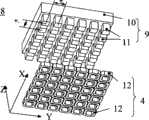
如图2、3所示,由图可知本发明所述磁浮XY工作台由基台1和移动台2组成,所述基台1存在一与XY平面平行的基台顶面23,所述移动台2存在一与XY平面平行的移动台底面24,所述基台顶面23与所述移动台底面24相对布置。所述磁浮XY工作台未工作时,由于所述移动台2受到重力作用,移动台底面24和基台项面23互相贴合;所述磁浮XY工作台工作时,所述移动台2受到悬浮力的作用被抬起,基台顶面23和移动台底面24之间存在一个很小的间隙25。其中,基台1由底座3和设置于底座3上的平面永磁阵列5组成,所述移动台2由平台7和设置于平台7底部的若干磁足单元8组成,所述若干磁足单元8沿XY平面布置,所述磁足单元8的底面与XY平面平行。As shown in Figures 2 and 3, it can be seen from the figure that the magnetic levitation XY workbench of the present invention is composed of a
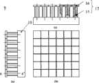
所述平面永磁阵列5由一系列永磁体6按一定规律在底座3上排列而成,图4给出了平面永磁阵列5的一种形式及其与底座3之间的安装关系。所述永磁阵列5由一组块状永磁体6沿XY面排列而成,其中,两相邻永磁体轴线间的距离τ为极距,称为永磁阵列极距。所述块状永磁体6沿竖直方向(Z向或-Z向)被磁化。所述永磁阵列5中,沿X向和沿Y向任意相邻永磁体之间的磁化方向相反,即一个永磁体磁化方向为Z向,另一个永磁体磁化方向为-Z向。图4中标注在永磁表面上的N和S表示该永磁体位于上部的磁极名称。平面永磁阵列5在基台1和移动台2之间的气隙25中产生气隙磁场,图5是图4所示永磁阵列的气隙磁感应强度Z方向分量Bz关于XY坐标的变化关系示意图。图5中永磁阵列的气隙磁感应强度两相邻峰值之间的距离等于永磁阵列极距τ。The planar
图6和图7说明了所述磁足单元8的具体结构,其中图6是磁足单元的三维分解视图,而图7为磁足单元8的三维视图。由图可知,所述磁足单元8包含一个线圈阵列4和一个由铁磁材料制成的磁足铁心9。所述磁足铁心9由铁心体10和一系列铁心齿11构成,所述铁心齿11与所述铁心体10固连。所述一系列铁心齿11沿XY平面按照矩阵形式布置而成,使得沿X方向任意相邻铁心齿和沿Y方向任意相邻铁心齿之间的中心距τt等于永磁阵列的极距τ的三分之一。所述线圈阵列4由若干线圈12组成。所述线圈12的数量与所述铁心齿11的数量一样,所述线圈12分别镶嵌于所述铁心齿11上。于是,沿X方向任意相邻线圈和沿Y方向任意相邻线圈之间的中心距τc也等于永磁阵列的极距 的三分之一,其中沿X方向任意相邻线圈和沿Y方向任意相邻线圈之间的中心距τc表示在图8中。6 and 7 illustrate the specific structure of the
所述铁心齿11具有多种形状。第一种是其沿轴线的任意截面轮廓形状均相同的铁心齿,可称之为柱状铁心齿。在此给出所述柱状铁心齿的两种实现形式,分别如图9和图10,其中,图9显示了截面轮廓形状为方形的柱状铁心齿13,图10显示了截面轮廓形状为圆形的柱状铁心齿14,图中aa’为铁心齿的轴线。所述柱状铁心齿的实现形式不限于所描述的两种,还有其他具体实现方式。The
第二种是非柱状铁心齿,其沿轴线aa’的截面形状不总相同,其典型的形式如图11所示,该非柱状铁心齿17包含齿体15和齿靴16两部分,为清晰期间,图中除表示非柱状铁心齿17之外,还表示出了与非柱状铁心齿17相连的铁心体10。所述齿体15一端与铁心体10相连的,另一端与齿靴16相连。所述齿靴16的截面的尺寸大于所述齿体15的尺寸。其作用之一是实现缠绕于所述非柱状铁心齿17上线圈的轴向固定。具有齿靴结构的非柱状铁心齿17的好处是:减小励磁磁场的漏磁,使永磁阵列5产生的磁力线大部分穿过铁心齿17和铁心体10而闭合。此外,具有齿靴结构的铁心齿还能够一定程度上降低齿槽效应,从而提高磁浮工作台工作性能。所述非柱状铁心齿17的实现形式不限于所描述的两种,还有其他具体实现方式。The second type is a non-columnar core tooth, whose cross-sectional shape along the axis aa' is not always the same, and its typical form is shown in Figure 11. The
本发明所述线圈12的形状也有多种形式:第一种形状是方形,如图12(a)所示;第种形状是圆形,如图12(b)所示;第三种形状是方形,如图12(c)所示。所述线圈12的实现形式不限于所描述的两种,还有其他具体实现方式。The shape of the
图12说明了本发明所述线圈阵列4的电气连接方法。所述线圈阵列4中的线圈12被划分为9组,各组线圈编号分别为W11、W12、W13、W21、W22、W23、W31、W32和W33,并进一步将所述各组线圈分别称之为W11相绕组、W12相绕组、W13相绕组、W21相绕组、W22相绕组、W23相绕组、W31相绕组、W32相绕组和距W33相绕组。所述相绕组Wmn(m=1,2或3,n=1,2或3)中,沿X向任意两相邻线圈的中心距和沿Y向任意两相邻线圈的中心距相等,且等于所述永磁阵列中心距τ,即图13中τph=τ。所述相绕组Wmn(m=1,2或3,n=1,2或3)中,各线圈相互串联,使得沿X向任意两相邻线圈和沿Y向任意两相邻线圈的电流旋向相反。图13中表示了相绕组W11中各线圈电流的旋向,其中18为逆时针电流方向,而19为顺时针电流方向,它们正好相反。以此类推,其他任意相绕组W12、W13、W21、W22、W23、W31、W32或W33中的线圈电流旋向之间关系与相绕组W11中中各线圈电流旋向关系一样。图14给出了某一相绕组Wmn(m=1,2或3,n=1,2或3)中各线圈的连接方式,当从绕组端口A或B输入激励电流后,沿X向任意两相邻线圈和沿Y向任意两相邻线圈的电流旋向相反,如图14中箭头所示,其中18为逆时针电流方向,而19为顺时针电流方向。Fig. 12 illustrates the electrical connection method of the
记ωx为磁足单元8产生的气隙磁场沿X向平移的角速度,ωy为磁足单元产生的气隙磁场沿Y向平移的角速度,Imax为相电流的最大值,则当相绕组Wmn(m=1,2或3,n=1,2或3)中的电流imn满足如下表达式:Note that ωx is the angular velocity of the air gap magnetic field generated by the
imn=0.5Imax[sin(ωxτ+2π/(m-1))+sin(ωyt+2π/(n-1))]imn =0.5Imax [sin(ωx τ+2π/(m-1))+sin(ωy t+2π/(n-1))]
时,磁足单元8在基台1和移动台2之间的气隙中产生磁足气隙磁场,所述磁足气隙磁场的磁感应强度Z方向分量Bz变化情况如图15所示,所述磁足气隙磁场的磁感应强度任意两相邻峰值之间的距离等于永磁阵列极距τ。所述磁足气隙磁场可相对于磁足单元8运动,图15中vx和vy分别为气隙磁场关于磁足单元8的相对平移速度沿X向和Y向的分量,其中,vx和vy分别可由角速度换ωx和ωy算出,即vx=2πωx,vy=2πωy。在磁足单元8产生的电枢气隙磁场和平面永磁阵列5产生的气隙磁场的相互作用下,磁足单元8受到3个分力F′x、F′y和F′z的作用,分别沿物体坐标系ox′y′z′的x′轴、y′轴和z′轴,所述物体坐标系固连于移动台2上,如图16所示。, the
图17表示了移动台具有4个电枢单元驱动时的受力情况,4个电枢单元分别称为第一电枢单元、第二电枢单元、第三电枢单元和第四电枢单元,它们底面的中心分别为O1、O2、O3和O4。图中ABCD为移动台2的底面,abcd为ABCD在基台10顶面上的投影。第i个(i=1,2,3,4)电枢单元的3个方向分量F′xi、F′yi和F′zi作用于该电枢单元底面的中心O′i,于是在上述力分量的作用下,移动台实现延x、y方向的运动和沿z方向的悬浮。Figure 17 shows the force situation when the mobile station has four armature units driven, and the four armature units are respectively called the first armature unit, the second armature unit, the third armature unit and the fourth armature unit , and the centers of their bottom surfaces are O1 , O2 , O3 and O4 , respectively. In the figure, ABCD is the bottom surface of the
Claims (8)
Translated fromChinesePriority Applications (1)
| Application Number | Priority Date | Filing Date | Title |
|---|---|---|---|
| CNA2008100361517ACN101286368A (en) | 2008-04-17 | 2008-04-17 | Multi-magnetic foot-driven large-scale maglev flat workbench |
Applications Claiming Priority (1)
| Application Number | Priority Date | Filing Date | Title |
|---|---|---|---|
| CNA2008100361517ACN101286368A (en) | 2008-04-17 | 2008-04-17 | Multi-magnetic foot-driven large-scale maglev flat workbench |
Publications (1)
| Publication Number | Publication Date |
|---|---|
| CN101286368Atrue CN101286368A (en) | 2008-10-15 |
Family
ID=40058504
Family Applications (1)
| Application Number | Title | Priority Date | Filing Date |
|---|---|---|---|
| CNA2008100361517APendingCN101286368A (en) | 2008-04-17 | 2008-04-17 | Multi-magnetic foot-driven large-scale maglev flat workbench |
Country Status (1)
| Country | Link |
|---|---|
| CN (1) | CN101286368A (en) |
Cited By (8)
| Publication number | Priority date | Publication date | Assignee | Title |
|---|---|---|---|---|
| CN103481166A (en)* | 2013-09-07 | 2014-01-01 | 江苏海建股份有限公司 | Novel grinding machine tool |
| CN103955137A (en)* | 2014-05-07 | 2014-07-30 | 西北工业大学 | Distributed electromagnetic array coupling electromagnetic force compound control method |
| CN106571731A (en)* | 2015-10-08 | 2017-04-19 | 上海微电子装备有限公司 | Superconductor maglev planar motor |
| CN107482955A (en)* | 2017-08-28 | 2017-12-15 | 清华大学 | A Planar Motor Structure Driven in Series and Its Thrust Calculation Method |
| CN107813294A (en)* | 2017-10-31 | 2018-03-20 | 梅其珍 | A kind of nonmetal flexible anthropomorphic robot |
| CN110103039A (en)* | 2019-04-15 | 2019-08-09 | 宁波海迈克精密机械制造有限公司 | A kind of magnetic worktable |
| CN110313120A (en)* | 2017-01-31 | 2019-10-08 | C.C.M.贝希尔公司 | flat positioning device |
| CN114400829A (en)* | 2022-02-19 | 2022-04-26 | 哈尔滨理工大学 | Two-degree-of-freedom magnetic-driven platform and control method |
- 2008
- 2008-04-17CNCNA2008100361517Apatent/CN101286368A/enactivePending
Cited By (15)
| Publication number | Priority date | Publication date | Assignee | Title |
|---|---|---|---|---|
| CN103481166A (en)* | 2013-09-07 | 2014-01-01 | 江苏海建股份有限公司 | Novel grinding machine tool |
| CN103481166B (en)* | 2013-09-07 | 2016-06-22 | 江苏海建股份有限公司 | grinding machine |
| CN103955137A (en)* | 2014-05-07 | 2014-07-30 | 西北工业大学 | Distributed electromagnetic array coupling electromagnetic force compound control method |
| CN103955137B (en)* | 2014-05-07 | 2017-02-15 | 西北工业大学 | Distributed electromagnetic array coupling electromagnetic force compound control method |
| CN106571731A (en)* | 2015-10-08 | 2017-04-19 | 上海微电子装备有限公司 | Superconductor maglev planar motor |
| CN106571731B (en)* | 2015-10-08 | 2019-04-12 | 上海微电子装备(集团)股份有限公司 | A kind of superconductor levitation planar motor |
| US11201533B2 (en) | 2017-01-31 | 2021-12-14 | C.C.M. Beheer B.V. | Planar positioning device |
| CN110313120B (en)* | 2017-01-31 | 2021-10-29 | C.C.M.贝希尔公司 | flat positioning device |
| CN110313120A (en)* | 2017-01-31 | 2019-10-08 | C.C.M.贝希尔公司 | flat positioning device |
| CN107482955B (en)* | 2017-08-28 | 2019-05-10 | 清华大学 | A series-driven planar motor structure and its thrust calculation method |
| CN107482955A (en)* | 2017-08-28 | 2017-12-15 | 清华大学 | A Planar Motor Structure Driven in Series and Its Thrust Calculation Method |
| CN107813294B (en)* | 2017-10-31 | 2019-01-01 | 梅其珍 | A kind of nonmetal flexible anthropomorphic robot |
| CN107813294A (en)* | 2017-10-31 | 2018-03-20 | 梅其珍 | A kind of nonmetal flexible anthropomorphic robot |
| CN110103039A (en)* | 2019-04-15 | 2019-08-09 | 宁波海迈克精密机械制造有限公司 | A kind of magnetic worktable |
| CN114400829A (en)* | 2022-02-19 | 2022-04-26 | 哈尔滨理工大学 | Two-degree-of-freedom magnetic-driven platform and control method |
Similar Documents
| Publication | Publication Date | Title |
|---|---|---|
| CN101610054B (en) | Planar motor adopting three-dimensional permanent magnet array | |
| CN102097982B (en) | Permanent-magnet synchronous magnetic suspension planar motor | |
| CN101286368A (en) | Multi-magnetic foot-driven large-scale maglev flat workbench | |
| CN101214617A (en) | Moving coil large-range mobile maglev six-degree-of-freedom workbench | |
| CN102723842B (en) | Multi-freedom and long travel magnetic suspension working bench | |
| CN101609265B (en) | Silicon slice platform multi-platform exchange system adopting magnetic levitation planar motor | |
| CN100521468C (en) | Permanent-magnet synchronous planar motor | |
| CN209088784U (en) | An ironless linear motor | |
| CN101741290B (en) | Magnetic suspension inching platform with six degrees of freedom | |
| CN101741289B (en) | Short stroke multiple freedom degree magnetic levitation planar motor | |
| CN101610022B (en) | Planar motor adopting groove-type coil | |
| CN102594220A (en) | Magnetic suspension planar motor with superconductor excitation structure | |
| CN204835879U (en) | Two side C types do not have iron core linear motor motion module | |
| CN101710779A (en) | Long stroke synchronous planar motor with integrated winding structure | |
| CN108173408B (en) | Three-degree-of-freedom positioning platform | |
| CN101752983B (en) | Long-travel high-accuracy multiple-degree-of-freedom planar motor | |
| CN204271955U (en) | A coil stacked moving coil planar motor | |
| CN101599677B (en) | Composite current drive nine-phase planar motor, linear-rotary motor and its driver | |
| CN115922365B (en) | Salient pole magnetic flux combined type electromagnetic module X-Y-R working platform | |
| CN104218771A (en) | Magnetic-suspension permanent-magnet synchronous planar motor with multiple degrees of freedom | |
| CN101800460B (en) | Short stroke DC planar motor with integrated winding structure | |
| CN102739122B (en) | Magnetic suspension flat motor with primary structure on both sides | |
| CN100552827C (en) | Large range moving magnetic suspension planar working table | |
| CN104218770B (en) | Be nested winding type permanent magnetic synchronous plane electromotor motor more | |
| CN204205908U (en) | A kind of heterogeneous nested winding type permanent magnetic synchronous plane electromotor motor |
Legal Events
| Date | Code | Title | Description |
|---|---|---|---|
| C06 | Publication | ||
| PB01 | Publication | ||
| C10 | Entry into substantive examination | ||
| SE01 | Entry into force of request for substantive examination | ||
| C02 | Deemed withdrawal of patent application after publication (patent law 2001) | ||
| WD01 | Invention patent application deemed withdrawn after publication | Open date:20081015 |