CN101286058A - Robot modular distributed adaptive control system and method - Google Patents
Robot modular distributed adaptive control system and methodDownload PDFInfo
- Publication number
- CN101286058A CN101286058ACNA2008100365715ACN200810036571ACN101286058ACN 101286058 ACN101286058 ACN 101286058ACN A2008100365715 ACNA2008100365715 ACN A2008100365715ACN 200810036571 ACN200810036571 ACN 200810036571ACN 101286058 ACN101286058 ACN 101286058A
- Authority
- CN
- China
- Prior art keywords
- robot
- equipment
- module
- joint
- programming
- Prior art date
- Legal status (The legal status is an assumption and is not a legal conclusion. Google has not performed a legal analysis and makes no representation as to the accuracy of the status listed.)
- Granted
Links
Images


Classifications
- Y—GENERAL TAGGING OF NEW TECHNOLOGICAL DEVELOPMENTS; GENERAL TAGGING OF CROSS-SECTIONAL TECHNOLOGIES SPANNING OVER SEVERAL SECTIONS OF THE IPC; TECHNICAL SUBJECTS COVERED BY FORMER USPC CROSS-REFERENCE ART COLLECTIONS [XRACs] AND DIGESTS
- Y02—TECHNOLOGIES OR APPLICATIONS FOR MITIGATION OR ADAPTATION AGAINST CLIMATE CHANGE
- Y02P—CLIMATE CHANGE MITIGATION TECHNOLOGIES IN THE PRODUCTION OR PROCESSING OF GOODS
- Y02P90/00—Enabling technologies with a potential contribution to greenhouse gas [GHG] emissions mitigation
- Y02P90/02—Total factory control, e.g. smart factories, flexible manufacturing systems [FMS] or integrated manufacturing systems [IMS]
Landscapes
- Numerical Control (AREA)
- Manipulator (AREA)
Abstract
Translated fromChinese
Description
Translated fromChinese技术领域technical field
本发明涉及一种机器人技术领域的控制系统及方法,具体是一种基于公共对象请求代理(CORBA)技术的机器人模块化分布式自适应控制系统及方法。The invention relates to a control system and method in the technical field of robots, in particular to a robot modular distributed adaptive control system and method based on Common Object Request Broker (CORBA) technology.
背景技术Background technique
为了适应家庭、公共场所等非结构环境下的导航、协作等工作,机器人控制系统需要集成不同的外围设备(如电机驱动器、视觉传感器、激光传感器等)和特定的应用软件,有的还需要在不同的软硬件平台间移植,要求机器人必须具备开放式、分布式模块化、自适应系统结构及相关控制方法。In order to adapt to navigation and collaboration in unstructured environments such as homes and public places, the robot control system needs to integrate different peripheral devices (such as motor drivers, vision sensors, laser sensors, etc.) Transplantation between different software and hardware platforms requires that the robot must have an open, distributed modular, self-adaptive system structure and related control methods.
CORBA是国际标准化组织OMG(对象管理组)于1991年发布的构造异构分布式系统结构的技术规范,它定义了分布式对象如何互操作,目的是使基于对象的部件在分布式环境下可重用、可移植和可互操作。它为可移植的、面向对象的分布式计算应用程序提供了不依赖于平台的编程接口和模型。它不依赖于编程语言、计算平台、网络协议的特点,使它十分适合于分布式系统应用程序的开发和系统集成,为机器人集成不同平台应用系统提供了一种可靠的接口方案。CORBA is a technical specification for constructing heterogeneous distributed system structures released by the International Organization for Standardization OMG (Object Management Group) in 1991. It defines how distributed objects interoperate, with the purpose of making object-based components available in a distributed environment. Reusable, portable and interoperable. It provides a platform-independent programming interface and model for portable, object-oriented distributed computing applications. It does not depend on the characteristics of programming language, computing platform and network protocol, which makes it very suitable for the development and system integration of distributed system applications, and provides a reliable interface solution for robots integrating different platform application systems.
经对现有技术的文献检索发现,中国专利公开号CN1938660,专利名称为:模块化机器及动态配置其拓扑结构的相应方法,该专利申请自述为:“本发明涉及一种动态配置模块化机器的拓扑结构的方法,该模块化机器的机器模块相互之间以及和控制装置之间通过网络连接。发明还涉及一种这样的模块化机器。”该发明主要是为实现模块化机器在实施工程时能够采集通信的拓扑结构并确定相应的通信配置,使工程系统在不考虑机器模块通信网络的拓扑结构的情况下仍可以进行通讯并执行其任务。其不足之处:该方法只能采集通信的拓扑结构信息,不能描述每个设备的属性服务信息,不能满足模块化机器人的分布式控制和各模块的集成需要。因此,研究一种具有一定自适应能力的模块化机器人控制方法和相关系统,实现对机器人功能的灵活定制与集成,以及实现机器人系统对不同设备模块化自适应控制和协同仿真,使机器人集成不同的功能模块更为方便、快捷,为机器人的普及提供了一种切实可行的模块化分布式自适应控制方法与系统。After searching the literature of the prior art, it is found that Chinese patent publication number CN1938660, the patent name is: modular machine and corresponding method for dynamically configuring its topology structure, and the patent application reads as: "The present invention relates to a dynamic configuration of modular machine The method of the topological structure of the modular machine, the machine modules of the modular machine are connected to each other and the control device through a network. The invention also relates to a kind of such modular machine.” This invention is mainly to realize the modular machine in the implementation of the project It can collect the communication topology and determine the corresponding communication configuration, so that the engineering system can still communicate and perform its tasks without considering the topology of the machine-module communication network. Its shortcoming: this method can only collect the topological structure information of communication, but cannot describe the attribute service information of each device, and cannot meet the distributed control of modular robots and the integration needs of each module. Therefore, it is necessary to study a modular robot control method and related systems with certain self-adaptive capabilities, realize flexible customization and integration of robot functions, and realize modular adaptive control and co-simulation of robot systems for different equipment, so that robot integration is different. The functional modules of the present invention are more convenient and faster, and provide a feasible modular distributed adaptive control method and system for the popularization of robots.
发明内容Contents of the invention
本发明的目的在于针对现有技术的不足,提出了一种机器人模块化分布式自适应控制系统及方法,使其解决了机器人系统对不同功能模块自适应连接、配置与控制功能。The purpose of the present invention is to address the deficiencies of the prior art, and propose a modular distributed adaptive control system and method for robots, which solves the functions of adaptive connection, configuration and control of different functional modules of the robot system.
本发明是通过以下技术方案实现的:The present invention is achieved through the following technical solutions:
本发明所涉及的机器人模块化分布式自适应控制系统,包括:设备池模块、设备管理模块、应用模块。The robot modular distributed adaptive control system involved in the present invention includes: an equipment pool module, an equipment management module, and an application module.
所述的设备池模块,就是机器人系统包含的所有设备集合,每个设备对各种物理设备进行抽象,将设备对应的硬件驱动、应用程序接口(API)进行封装,如移动车体设备,机械臂设备,机械手等设备。每个设备对外提供IDL(接口定义语言)进行定义的,符合CORBA规范的控制接口。在每个CORBA设备接口中,定义Service_Context()函数记录设备服务上下文信息,用以描述接口设备对外的各种服务。用户可以在没有完整了解模块全部功能的情况下,通过访问接口中的Service_Context()函数,获取设备中的服务上下文信息,从而在无人干预的情况下了解和掌握如何获取和使用设备的方法,从而实现对不同设备的自适应连接、配置与控制功能,实现基于CORBA技术的机器人设备控制的智能性。The device pool module is a collection of all devices included in the robot system, each device abstracts various physical devices, and encapsulates the hardware drivers and application program interfaces (APIs) corresponding to the devices, such as mobile car body equipment, mechanical Arm equipment, manipulator and other equipment. Each device provides a control interface defined by IDL (Interface Definition Language) and conforms to the CORBA specification. In each CORBA device interface, define the Service_Context() function to record the device service context information, which is used to describe various external services of the interface device. The user can obtain the service context information in the device by accessing the Service_Context() function in the interface without fully understanding all the functions of the module, so as to understand and master how to obtain and use the device without human intervention. In this way, the adaptive connection, configuration and control functions of different devices can be realized, and the intelligence of robot device control based on CORBA technology can be realized.
所述的设备管理模块,负责将机器人设备池模块中的各种设备进行有序的组织,写入设备管理模块的设备注册表中,用以记录机器人使用设备的工作状态和级联顺序。由于每个设备都是通过CORBA规范进行封装,可以根据需要方便地将任意设备加载和摘离CORBA软总线,用户可以通过修改设备注册表来设计并定制不同设备资源构成所需要的机器人系统。The device management module is responsible for organizing various devices in the robot device pool module in an orderly manner, and writing them into the device registry of the device management module to record the working status and cascading sequence of the devices used by the robot. Since each device is encapsulated by the CORBA specification, any device can be easily loaded and removed from the CORBA soft bus as needed. Users can design and customize the robot system required by different device resources by modifying the device registry.
所述的应用模块,包括:编程控制模块和3D仿真模块。其中,编程控制模块提供用户对已定制的机器人进行编程控制的服务;3D仿真模块负责对已定制机器人的3D运动学仿真服务。应用模块可以通过CORBA总线访问设备管理模块中设备注册表,进行个性化查询、获取相关设备的信息,并通过访问设备上下文获取设备的使用方法和设备的工作状态。The application module includes: a programming control module and a 3D simulation module. Among them, the programming control module provides users with the service of programming and controlling the customized robot; the 3D simulation module is responsible for the 3D kinematics simulation service of the customized robot. The application module can access the device registry in the device management module through the CORBA bus, perform personalized queries, obtain information about related devices, and obtain the usage method and working status of the device by accessing the device context.
本发明所涉及的机器人模块化分布式自适应控制方法,用于实现了机器人系统对功能模块自适应连接、配置与控制,具体包括以下步骤:The robot modular distributed adaptive control method involved in the present invention is used to realize the adaptive connection, configuration and control of the functional modules of the robot system, and specifically includes the following steps:
第一步,机器人设备定制。用户通过人机交互的形式回答一系列问题来定制自己需要的机器人系统。如机器人是否具有移动车体,是否采用机械臂,如果有机械臂,机械臂的数量,它们在车体上的安装位置,每个机械臂具有几个关节;有无机械手等,确定设备的几何形状及其它们之间的装配关系并将其写入到设备管理模块中。The first step is robot equipment customization. Users answer a series of questions in the form of human-computer interaction to customize the robot system they need. For example, whether the robot has a mobile body, whether it uses a mechanical arm, if there is a mechanical arm, the number of mechanical arms, their installation positions on the vehicle body, and how many joints each mechanical arm has; whether there is a mechanical arm, etc., determine the geometry of the equipment Shapes and their assembly relationships are written into the device management module.
第二步,设备的电气控制线路连接:在编制程序前,通过CAN总线将机械臂设备内的各个关节电机及控制器连接起来;通过CAN总线将机械灵巧手设备内的关节电机及控制器连接起来;通过串行通信接口将运动电机及控制器连接起来。通过以太网将各个设备联系起来,并通过CORBA的ORB总线实现设备间通讯。The second step is to connect the electrical control circuit of the equipment: before programming, connect the joint motors and controllers in the robotic arm equipment through the CAN bus; connect the joint motors and controllers in the mechanical dexterous hand equipment through the CAN bus Get up; connect the motion motor and controller through the serial communication interface. Connect each device through Ethernet, and realize communication between devices through ORB bus of CORBA.
第三步,设备在线注册:当设备模块被选入参与构成系统时,首先向设备管理模块进行注册,设备管理模块为新加入设备分配一个唯一的设备标号(deviceID),并将设备标号,类型写入设备注册表。The third step is online device registration: when the device module is selected to participate in the system, it first registers with the device management module. The device management module assigns a unique device ID (deviceID) to the newly added device, and the device ID, type Write to the device registry.
第四步,应用模块对系统中设备的在线查询:编程控制模块提供的图形化编程控制服务:首先它需要访问设备注册表,获取相关设备的服务信息,包括机器人有有无车体,有无机械臂,有无机械手等,获取它们的几何形状及其它们之间的装配关系。在仿真模块中按照几何形状将各个设备进行重构,并按照从设备注册表中获取的装配关系完成虚拟装配与3D显示;在设备注册表中进一步获取各个CORBA规范的设备代理,通过调用设备CORBA接口的上下文掌握设备获取和设备的使用方法,并将此设备参数显示在编程控制模块的用户界面(User Interface)上。The fourth step is the online query of the equipment in the system by the application module: the graphical programming control service provided by the programming control module: first, it needs to access the device registry to obtain the service information of related equipment, including whether the robot has a car body, whether Manipulator arms, with or without manipulators, etc., obtain their geometric shapes and the assembly relationship between them. In the simulation module, each device is reconstructed according to the geometric shape, and the virtual assembly and 3D display are completed according to the assembly relationship obtained from the device registry; further obtain the device agent of each CORBA specification in the device registry, and call the device CORBA The context of the interface grasps the method of device acquisition and device use, and displays the device parameters on the user interface (User Interface) of the programming control module.
第五步,调整设备的零点偏移,即调整机器人各个设备由于装配误差造成的零点漂移:先通过CORBA接口读取各设备上下文中存储的目前机器人设备的零点漂移设置。然后在编程控制模块的UI中用鼠标拖动机器人设备对应的拖动条,控制设备到达零点位置,并将设备当前的零点漂移设置存入相应设备的上下文中。The fifth step is to adjust the zero point offset of the equipment, that is, to adjust the zero point drift of each robot device due to assembly error: first read the current zero point drift setting of the robot device stored in the context of each device through the CORBA interface. Then use the mouse to drag the drag bar corresponding to the robot device in the UI of the programming control module to control the device to reach the zero position, and store the current zero drift setting of the device in the context of the corresponding device.
第六步,设置机器人初始位姿,保存到对应的设备上下文中。The sixth step is to set the initial pose of the robot and save it to the corresponding device context.
第七步,利用编程控制模块实施编程。The seventh step is to use the programming control module to implement programming.
第八步,保存编辑好的程序脚本文件。The eighth step is to save the edited program script file.
第九步,3D仿真验证:进入仿真模式,利用3D仿真模块在三维仿真环境中检验控制程序文件各个状态图标中位姿数据的合理性。如果发现某些机器人的状态位姿数据不合理,可在编程控制模块中对控制程序文件直接修改。The ninth step, 3D simulation verification: enter the simulation mode, and use the 3D simulation module to check the rationality of the pose data in each status icon of the control program file in the 3D simulation environment. If the state pose data of some robots is found to be unreasonable, the control program file can be directly modified in the programming control module.
第十步,实际机器人的程序脚本文件下载:经3D仿真模块验证满意后,编程控制模块选择进入“实际机器人控制模式”,将程序脚本文件通过CORBA总线下载到各个物理设备对应的指令存储器中保存。Step 10: Download the program script file of the actual robot: After the 3D simulation module is verified to be satisfactory, the programming control module selects to enter the "actual robot control mode", and downloads the program script file to the instruction memory corresponding to each physical device through the CORBA bus for storage .
第十一步,控制实际机器人执行程序脚本文件:通过编程控制模块控制实际机器人执行程序脚本文件,如果有需要调整某个关节角度,将根据情况跳至第九步。The eleventh step is to control the actual robot to execute the program script file: to control the actual robot to execute the program script file through the programming control module. If it is necessary to adjust a certain joint angle, it will skip to the ninth step according to the situation.
由于改进CORBA接口技术,加入描述设备功能的上下文信息,编程控制模块可以通过访问模块设备中的上下文信息,从而在无人干预的情况下了解和掌握如何获取和使用设备的方法,实现了对不同设备的自适应连接、配置与控制,从而实现了基于CORBA技术的机器人设备控制的智能性。Due to the improvement of CORBA interface technology and the addition of context information describing device functions, the programming control module can understand and master how to obtain and use the device without human intervention by accessing the context information in the module device. The adaptive connection, configuration and control of equipment realize the intelligence of robot equipment control based on CORBA technology.
附图说明Description of drawings
图1为本发明基于CORBA的机器人模块系统构成图。Fig. 1 is a structural diagram of the robot module system based on CORBA in the present invention.
图2为本发明设备管理模块及移动车体设备上下文构成图。Fig. 2 is a context composition diagram of the equipment management module and the mobile vehicle body equipment of the present invention.
图3为本发明机械臂设备上下文构成图。Fig. 3 is a diagram of the context structure of the robot arm device of the present invention.
图4为本发明机械手设备上下文构成图。Fig. 4 is a diagram of the context structure of the manipulator device of the present invention.
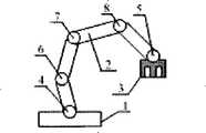
图5为本发明为机械臂与机械灵巧定制组合而成的机器人。Fig. 5 is the robot that the present invention is the combination of manipulator arm and mechanical dexterous customization.
图6为本发明为移动车体、机械臂与机械灵巧定制组合而成的机器人。Fig. 6 is the robot that the present invention is custom-made combination of mobile car body, mechanical arm and mechanical dexterity.
图7为本发明为移动车体、2个机械臂与2个机械灵巧定制组合而成的机器人。Fig. 7 is the robot that the present invention is a mobile car body, 2 mechanical arms and 2 mechanical dexterous custom combinations.
其中,附图标记:Among them, reference signs:
图5中:1:固定基座,2:四连杆的机械臂设备,3:机械手设备;4:为固定基座1的设备装配位(通过铰链连接机械臂等其他标准设备);5:为机械臂2的设备装配位(通过铰链连接机械手、机械臂或其他标准设备);6,7,8:为四连杆机械臂2的转动关节(Joint);In Fig. 5: 1: fixed base, 2: four-link mechanical arm equipment, 3: manipulator equipment; 4: equipment assembly position for fixed base 1 (connecting mechanical arms and other standard equipment through hinges); 5: It is the equipment assembly position of the robot arm 2 (connect the robot arm, robot arm or other standard equipment through a hinge); 6, 7, 8: are the rotary joints (Joint) of the four-link robot arm 2;
图6中:9:移动车体设备,10:四连杆的机械臂设备,11:机械手设备;12,13,14:移动车体设备9的设备装配位(9通过铰链连接机械臂等其他标准设备);15:四连杆的机械臂设备10的设备装配位;Among Fig. 6: 9: mobile car body equipment, 10: mechanical arm equipment of four links, 11: manipulator equipment; 12, 13, 14: the equipment assembly position of mobile car body equipment 9 (9 connects mechanical arm etc. by hinge standard equipment); 15: the equipment assembly position of the mechanical arm equipment 10 of four linkages;
图7中:16:移动车体设备,17,18:三连杆的机械臂设备,19,20:机械手设备;21,22:移动车体设备16的设备装配位(16通过铰链连接机械臂等其他标准设备);23:三连杆机械臂设备17的设备装配位;24:三连杆机械臂设备18的设备装配位。Among Fig. 7: 16: mobile car body equipment, 17,18: the mechanical arm equipment of three linkages, 19,20: manipulator equipment; 21,22: the equipment assembly position of mobile car body equipment 16 (16 connects mechanical arm by hinge and other standard equipment); 23: the equipment assembly position of the three-link mechanical arm equipment 17; 24: the equipment assembly position of the three-link mechanical arm equipment 18.
具体实施方式Detailed ways
下面结合附图对本发明的实施例作详细说明:本实施例在以本发明技术方案为前提下进行实施,给出了详细的实施方式,但本发明的保护范围不限于下述的实施例。The embodiments of the present invention are described in detail below in conjunction with the accompanying drawings: the present embodiment is implemented on the premise of the technical solution of the present invention, and detailed implementation is provided, but the protection scope of the present invention is not limited to the following embodiments.
如图1所示,本发明系统的实施例包括:设备池模块,设备管理模块,应用模块。As shown in Fig. 1, the embodiment of the system of the present invention includes: a device pool module, a device management module, and an application module.
所述的设备池模块,就是机器人系统包含的逻辑设备集合,包括:移动车体设备,机械臂设备,机械手设备。每个逻辑设备负责对自身的物理硬件进行抽象,将设备对应的硬件驱动、应用程序接口(API)进行CORBA封装,对外提供IDL(接口定义语言)定义的、符合CORBA规范的控制接口,注册到设备管理模块的设备注册表中,供应用模块访问和使用。在每个CORBA设备接口中,也定义设备的服务上下文信息,用以描述接口设备对外提供的各种服务及使用方法。用户可以在没有完整了解模块全部功能的情况下,通过访问接口中的Service_Context()函数,获取设备中的服务上下文信息,从而使编程控制模块在无人干预的情况下了解和掌握获取设备的使用方法,即设备中各关节驱动电机的列表及各个电机的运行状态,并将其各个电机状态参数以对话框的形式在编程控制模块的UI中显示出来,供用户调用和修改,并将最终数据封装到一个状态图标中来表示机器人的一个状态位姿。通过顺序构建一定数目的状态图标组成机器人的动作序列,并保存到指定的程序脚本文件中,完成对机器人的图形化编程。The equipment pool module is a set of logical equipment contained in the robot system, including: mobile vehicle body equipment, mechanical arm equipment, and manipulator equipment. Each logical device is responsible for abstracting its own physical hardware, encapsulating the corresponding hardware driver and application program interface (API) in CORBA, and providing a control interface defined by IDL (Interface Definition Language) that conforms to the CORBA specification and registered in In the device registry of the device management module, it is accessed and used by the application module. In each CORBA device interface, the service context information of the device is also defined, which is used to describe various services provided by the interface device and usage methods. The user can obtain the service context information in the device by accessing the Service_Context() function in the interface without fully understanding all the functions of the module, so that the programming control module can understand and master the use of the device without human intervention method, that is, the list of drive motors for each joint in the device and the running status of each motor, and display the status parameters of each motor in the UI of the programming control module in the form of a dialog box for users to call and modify, and the final data Encapsulated into a state icon to represent a state pose of the robot. By constructing a certain number of status icons sequentially to form the action sequence of the robot, and saving it in the specified program script file, the graphical programming of the robot is completed.
设备中的服务上下文信息用于记录设备对外提供的各种服务及使用方法,是实现各个设备注册、自适应仿真和控制的关键。各个设备的上下文信息如下:如图2所示,移动车体设备的上下文包括:驱动电机链表,包含左、右两个驱动电机。移动车体采用双轮差速驱动方式,通过控制左、右两个电机实现机器人前进后退及左右旋转。每个驱动电机的服务上下文包括:电机ID、电机速度v,加速度a及初始的零点漂移量L等参数,并将此设备参数显示在编程控制模块的UI上。The service context information in the device is used to record various services and usage methods provided by the device, which is the key to realize the registration, self-adaptive simulation and control of each device. The context information of each device is as follows: As shown in FIG. 2 , the context of the mobile vehicle body device includes: a linked list of driving motors, including two driving motors, left and right. The mobile car body adopts a two-wheel differential drive mode, and the robot can move forward, backward and left and right by controlling the left and right two motors. The service context of each driving motor includes parameters such as motor ID, motor speed v, acceleration a and initial zero drift L, and display the device parameters on the UI of the programming control module.
如图3所示,机械臂设备的上下文包括:机械臂具有的关节链表和包含的关节数目。关节链表中记录了各个关节及关节之间的级联关系。每个关节的服务上下文包括:关节ID、几何尺寸描述、关节转换矩阵T,关节位姿P(x,y,z,Ψ,θ,Φ)描述,及对应驱动电机的控制参数,包括每个关节上电机的行程(及关节行程),电机运行速度v,加速度a及关节零点漂移量L等参数,并将此设备参数显示在编程控制模块的UI上。其中,关节位姿P(x,y,z,Ψ,θ,Φ)中,x为x轴方向坐标,y为y轴方向坐标,z为z轴方向坐标;Ψ为关节横滚角,θ为关节俯仰角,Φ为关节偏转角。其中横滚角Ψ,俯仰角θ,偏转角Φ的定义:在笛卡尔坐标系基础上,先绕Z轴旋转角度Ψ,再绕新的Y轴旋转角度θ,再绕新的X轴旋转角度Φ。这样实现了对机器人系统的自适应控制。机械手的上下文信息与机械臂相似,其组成如图4所示。机械手设备的上下文包括:机械手具有的关节链表和包含的关节数目。关节链表中记录了各个关节及关节之间的级联关系。每个关节的服务上下文包括:关节ID、几何尺寸描述、关节转换矩阵T,关节位姿P(x,y,z,Ψ,θ,Φ)描述,及对应驱动电机的控制参数,包括每个关节上电机的行程(及关节行程),电机运行速度v,加速度a及关节零点漂移量L等参数。As shown in FIG. 3 , the context of the robot arm device includes: the joint list of the robot arm and the number of included joints. Each joint and the cascading relationship between joints are recorded in the joint chain table. The service context of each joint includes: joint ID, geometric dimension description, joint transformation matrix T, joint pose P (x, y, z, Ψ, θ, Φ) description, and the control parameters of the corresponding drive motor, including each The stroke of the motor on the joint (and the stroke of the joint), the running speed of the motor v, the acceleration a and the joint zero point drift L and other parameters, and display the device parameters on the UI of the programming control module. Among them, in the joint pose P(x, y, z, Ψ, θ, Φ), x is the coordinate in the x-axis direction, y is the coordinate in the y-axis direction, z is the coordinate in the z-axis direction; Ψ is the joint roll angle, θ is the pitch angle of the joint, and Φ is the deflection angle of the joint. Among them, the definition of roll angle Ψ, pitch angle θ, and yaw angle Φ: on the basis of the Cartesian coordinate system, first rotate the angle Ψ around the Z axis, then rotate the angle θ around the new Y axis, and then rotate the angle around the new X axis Φ. In this way, the adaptive control of the robot system is realized. The context information of the manipulator is similar to that of the manipulator, and its composition is shown in Figure 4. The context of the manipulator device includes: the joint list of the manipulator and the number of joints it contains. Each joint and the cascading relationship between joints are recorded in the joint chain table. The service context of each joint includes: joint ID, geometric dimension description, joint transformation matrix T, joint pose P (x, y, z, Ψ, θ, Φ) description, and the control parameters of the corresponding drive motor, including each Parameters such as the stroke of the motor on the joint (and the stroke of the joint), the running speed v of the motor, the acceleration a, and the amount L of the joint zero point drift.
所述的设备管理模块,负责将机器人设备池模块中的各种设备进行有序的组织,写入设备管理模块的设备注册表中,用以记录机器人使用设备的工作状态和级联顺序。由于每个设备都是通过CORBA规范进行封装,可以根据需要方便地将任意设备加载和摘离CORBA软总线,用户可以通过修改设备注册表来设计并定制不同设备资源构成所需要的机器人系统。The device management module is responsible for organizing various devices in the robot device pool module in an orderly manner, and writing them into the device registry of the device management module to record the working status and cascading sequence of the devices used by the robot. Since each device is encapsulated by the CORBA specification, any device can be easily loaded and removed from the CORBA soft bus as needed. Users can design and customize the robot system required by different device resources by modifying the device registry.
所述的应用模块,包括:编程控制模块和3D仿真模块。其中,编程控制模块提供的编程控制服务;3D仿真模块负责机器人3D运动学仿真服务;每项服务可以通过CORBA总线调用设备注册表查询、获取相关设备的信息,并通过访问设备上下文获取设备的使用方法和设备的工作状态。The application module includes: a programming control module and a 3D simulation module. Among them, the programming control service provided by the programming control module; the 3D simulation module is responsible for the 3D kinematics simulation service of the robot; each service can call the device registry to query and obtain the information of related devices through the CORBA bus, and obtain the use of the device by accessing the device context The working state of the method and apparatus.
本发明方法实施例具体实现机器人系统对不同功能模块自适应连接、配置与控制,其过程包括11步:The embodiment of the method of the present invention specifically realizes the adaptive connection, configuration and control of different functional modules of the robot system, and the process includes 11 steps:
1.用户通过人机交互的形式回答一系列问题来定制机器人系统。如机器人是否具有移动车体,是否采用机械臂,如果采用机械臂,需要几个并指定它们在车体上的安装位置,每个机械臂具有几个关节;有无机械手等,获取它们的几何形状及其它们之间的装配关系。这样可以根据用户的各种个性化需要集成不同机器人设备,设备之间通过标准的铰链将每个设备需要连接的装配位连接在一起,从而完成快速定制各种个性化机器人系统。图5-图7为用户定制的3个的机器人系统典型用例。1. Users customize the robot system by answering a series of questions in the form of human-computer interaction. For example, whether the robot has a mobile body, whether it uses a mechanical arm, and if it uses a robotic arm, how many are needed and their installation positions on the vehicle body are specified, and each robotic arm has several joints; whether there is a robotic arm, etc., to obtain their geometry Shapes and their assembly relationships. In this way, different robot devices can be integrated according to the various individual needs of users, and the assembly positions that each device needs to be connected are connected together through standard hinges, so as to complete the rapid customization of various personalized robot systems. Figures 5-7 are typical use cases of three robot systems customized by users.
图5的用户定制机器人系统由一个四连杆的机械臂2与一个机械手3组合而成。系统通过固定基座1的设备装配位4用铰链将机械臂2与固定基座1连接在一起;通过机械臂2末端的设备装配位5将机械臂2与机械手3连为一体。该定制机器人可以从事装配、焊接等工业机器人的工作。The user-customized robot system in FIG. 5 is composed of a four-link mechanical arm 2 and a manipulator 3 . The system connects the mechanical arm 2 and the fixed base 1 with a hinge through the equipment assembly position 4 of the fixed base 1; the mechanical arm 2 and the manipulator 3 are connected as a whole through the equipment assembly position 5 at the end of the mechanical arm 2. The custom robot can do the work of industrial robots such as assembly and welding.
图6的用户定制机器人系统由一个移动车体9、一个四连杆的机械臂10与一个机械手11组合而成。移动车体9上具有3个设备装配位分别是12、13、14。通过移动车体9上的设备装配位14将四连杆机械臂10与移动车体9用铰链固定在一起。机械手15通过机械臂10上的装配位15用铰链连为一体。该定制机器人可完成移动装配、拿取工件等工作。The user-customized robot system in FIG. 6 is composed of a mobile car body 9 , a four-link mechanical arm 10 and a manipulator 11 . There are 3 equipment assembly positions 12, 13, 14 respectively on the mobile car body 9. The four-link mechanical arm 10 and the mobile vehicle body 9 are hingedly fixed together by the equipment assembly position 14 on the mobile vehicle body 9 . The manipulator 15 is hinged as a whole through the assembly position 15 on the manipulator 10 . The custom robot can do mobile assembly, pick up workpieces and more.
图7的用户定制机器人系统由一个移动车体16、两个三连杆的机械臂17、18与两个机械手19、20组合而成。移动车体16通过设备装配位21与机械臂17连接,通过设备装配位22与机械臂18连接,机械臂17通过设备装配位23与机械手19相连,机械臂18通过设备装配位24与机械手20连为一体。该定制机器人通过双机械臂协调完成较为复杂的协同工件装配等工作。The user-customized robot system of FIG. 7 is composed of a mobile car body 16, two three-link mechanical arms 17, 18 and two manipulators 19, 20. The mobile car body 16 is connected to the mechanical arm 17 through the equipment assembly position 21, and is connected to the mechanical arm 18 through the equipment assembly position 22. connected as one. The custom-made robot coordinates and completes relatively complex collaborative workpiece assembly and other tasks through dual robotic arms.
通过步骤1,用户可以根据需要定制多种不同的机器人系统。本实施例以下将以图6中的机器人系统为对象进行说明。Through step 1, users can customize many different robot systems according to their needs. This embodiment will be described below taking the robot system in FIG. 6 as an object.
2.设备的电气控制线路连接。在编制程序前,通过CAN总线将机械臂设备内的各个关节电机及控制器连接起来;通过CAN总线将机械手设备内的关节电机及控制器连接起来;通过串行通信接口将运动电机及控制器连接起来。通过以太网将各个设备联系起来,并通过CORBA的ORB总线实现设备间通讯。2. The electrical control circuit connection of the equipment. Before programming, connect the joint motors and controllers in the manipulator equipment through the CAN bus; connect the joint motors and controllers in the manipulator equipment through the CAN bus; connect the motion motors and controllers through the serial communication interface connect them. Connect each device through Ethernet, and realize communication between devices through ORB bus of CORBA.
3.被选中设备的在线注册:当设备模块被用户选入参与构成系统时,首先向设备管理模块进行注册,设备管理模块为新加入设备分配一个唯一的设备标号(deviceID),并将设备标号、设备类型写入设备注册表中。3. Online registration of the selected device: When the device module is selected by the user to participate in the system, it first registers with the device management module. The device management module assigns a unique device ID (deviceID) to the newly added device, and assigns the , The device type is written into the device registry.
4.应用模块对机器人系统中设备的在线查询:编程控制模块如果向用户提供图形化编程控制服务,它必须首先需要访问设备注册表,获取相关设备的服务信息,包括机器人有无车体,有无机械臂,有无机械手等,获取它们的几何形状及其它们之间的装配关系。在仿真模块中按照几何形状将各个设备进行重构,并按照从设备注册表中获取的装配关系完成虚拟装配与3D显示;在设备注册表中进一步获取各个CORBA规范的设备代理,通过调用设备CORBA接口的上下文掌握设备获取和设备的使用方法,并将此设备参数显示在编程控制模块的用户界面(User Interface)上。4. The online query of the equipment in the robot system by the application module: if the programming control module provides graphical programming control services to the user, it must first access the device registry to obtain service information about the relevant equipment, including whether the robot has a car body, whether it has Whether there is no robot arm, whether there is a robot arm, etc., to obtain their geometric shapes and the assembly relationship between them. In the simulation module, each device is reconstructed according to the geometric shape, and the virtual assembly and 3D display are completed according to the assembly relationship obtained from the device registry; further obtain the device agent of each CORBA specification in the device registry, and call the device CORBA The context of the interface grasps the method of device acquisition and device use, and displays the device parameters on the user interface (User Interface) of the programming control module.
5.调整机器人移动车体上的左右驱动电机及机械臂、机械手上各关节电机设备由于装配误差造成的零点漂移。先通过CORBA接口读取各设备上下文中存储的目前机器人电机的零点漂移设置。然后在编程控制模块的UI中用鼠标拖动机器臂、机械手各关节对应的拖动条,控制关节电机转动。当各个电机都转到零点位置时,将电机当前的零点漂移设置存入相应电机的设备上下文中。5. Adjust the left and right driving motors on the mobile body of the robot and the zero point drift caused by the assembly error of the joint motors on the mechanical arm and the manipulator. First read the current zero drift setting of the robot motor stored in the context of each device through the CORBA interface. Then use the mouse to drag the drag bar corresponding to each joint of the robot arm and the manipulator in the UI of the programming control module to control the rotation of the joint motor. When each motor is turned to the zero position, the current zero drift setting of the motor is stored in the device context of the corresponding motor.
6.设置机器人初始位姿:设置移动车体设备的初始位置坐标(x,y),机械臂设备和机械手设备中各个关节的初始角度信息,保存到对应的设备上下文中。6. Set the initial pose of the robot: set the initial position coordinates (x, y) of the mobile car body equipment, the initial angle information of each joint in the robotic arm equipment and the manipulator equipment, and save them in the corresponding equipment context.
7.利用编程控制模块实施编程。新建一个程序脚本文件(支持xml、txt、xls文件格式),调节和记录程序中各个状态图标的位置、姿态。选择“在线编程模式”,然后点取一个状态,选择机器人的可用设备(有移动车体、机械臂、机械手3种类型设备可选择),调节各个关节角度到理想位姿,之后设定各个设备中电机的运动速度后,按OK按钮,编程控制模块会将所有设备的情况(包括移动车体的位置、机械臂及机械手中各个关节的角度)存入状态图标中。7. Use the programming control module to implement programming. Create a new program script file (support xml, txt, xls file formats), adjust and record the position and posture of each status icon in the program. Select "online programming mode", then click a state, select the available equipment of the robot (there are three types of equipment to choose from: mobile body, mechanical arm, and manipulator), adjust the angles of each joint to the ideal pose, and then set each equipment After the movement speed of the motor is selected, press the OK button, and the programming control module will save the conditions of all equipment (including the position of the moving car body, the angle of the mechanical arm and each joint in the manipulator) into the status icon.
8.由若干个状态图标按照先后顺序一个基本机器人运动序列程序,记录在程序脚本文件中,从而形成一套比较完整的机器人运动控制程序。然后设置的机器人各个设备的输入输出(I/O)。为了支持不同电机设备的驱动及控制方式,编程控制模块程序为设备中的每个关节点机预留有2路输入(Input)和2路输出(Output)。当Input为Enable使能时,可选项有Output和Motion,选择Output时,该Output将只会被该Input触发,否则选择Motion,该Output将作为独立的Output输出;保存编辑好的程序脚本文件。8. A basic robot motion sequence program is recorded in the program script file according to the order of several status icons, thus forming a relatively complete set of robot motion control programs. Then set the input and output (I/O) of each device of the robot. In order to support the driving and control methods of different motor equipment, the programming control module program reserves 2 inputs (Input) and 2 outputs (Output) for each joint point machine in the equipment. When Input is Enabled, the options are Output and Motion. When Output is selected, the Output will only be triggered by the Input. Otherwise, Motion will be selected, and the Output will be output as an independent Output; save the edited program script file.
9.编程控制模块由第7步中的“在线编程模式”转换至“仿真模式”,利用3D仿真模块在三维仿真环境中检验程序脚本文件各个状态图标中位姿数据的合理性。如果发现某个状态图标的位姿数据不合理,可在编程控制模块中对程序脚本文件直接修改。9. The programming control module switches from the "online programming mode" in step 7 to the "simulation mode", and uses the 3D simulation module to check the rationality of the pose data in each status icon of the program script file in the 3D simulation environment. If the pose data of a status icon is found to be unreasonable, the program script file can be directly modified in the programming control module.
10.经3D仿真模块验证满意后,编程控制模块选择进入“实际机器人控制模式”,将程序脚本文件通过CORBA总线下载到各个物理设备对应的指令存储器中保存。10. After the verification by the 3D simulation module is satisfactory, the programming control module chooses to enter the "actual robot control mode", and downloads the program script file to the instruction memory corresponding to each physical device through the CORBA bus for storage.
11.通过编程控制模块控制实际机器人执行程序脚本文件。如果有需要调整某个关节角度,将根据情况跳至第9步。11. Control the actual robot to execute the program script file through the programming control module. If it is necessary to adjust a certain joint angle, skip to step 9 according to the situation.
由于改进CORBA接口技术,加入描述设备功能的上下文信息,编程控制模块可以通过访问模块设备中的上下文信息,从而在无人干预的情况下了解和掌握如何获取和使用设备的方法,实现了对不同设备的自适应控制,从而实现了基于CORBA技术的机器人设备控制方法的智能性。Due to the improvement of CORBA interface technology and the addition of context information describing device functions, the programming control module can understand and master how to obtain and use the device without human intervention by accessing the context information in the module device. The adaptive control of equipment realizes the intelligence of the robot equipment control method based on CORBA technology.
Claims (12)
Priority Applications (1)
| Application Number | Priority Date | Filing Date | Title |
|---|---|---|---|
| CN2008100365715ACN101286058B (en) | 2008-04-24 | 2008-04-24 | Robot modular distributed adaptive control system and method |
Applications Claiming Priority (1)
| Application Number | Priority Date | Filing Date | Title |
|---|---|---|---|
| CN2008100365715ACN101286058B (en) | 2008-04-24 | 2008-04-24 | Robot modular distributed adaptive control system and method |
Publications (2)
| Publication Number | Publication Date |
|---|---|
| CN101286058Atrue CN101286058A (en) | 2008-10-15 |
| CN101286058B CN101286058B (en) | 2010-09-29 |
Family
ID=40058289
Family Applications (1)
| Application Number | Title | Priority Date | Filing Date |
|---|---|---|---|
| CN2008100365715AExpired - Fee RelatedCN101286058B (en) | 2008-04-24 | 2008-04-24 | Robot modular distributed adaptive control system and method |
Country Status (1)
| Country | Link |
|---|---|
| CN (1) | CN101286058B (en) |
Cited By (33)
| Publication number | Priority date | Publication date | Assignee | Title |
|---|---|---|---|---|
| CN102929159A (en)* | 2012-11-19 | 2013-02-13 | 北京经纬恒润科技有限公司 | State control method and device for simulation model |
| CN103324173A (en)* | 2013-06-08 | 2013-09-25 | 上海交通大学 | Multiple-heterogeneous robot cooperation method based on middleware |
| CN103926928A (en)* | 2014-05-04 | 2014-07-16 | 威海正棋机电技术有限公司 | Robot controller with modules dynamically dispatched |
| WO2014110748A1 (en)* | 2013-01-17 | 2014-07-24 | Abb Technology Ltd. | Motion controller and robot control system using the same |
| CN104626166A (en)* | 2014-12-19 | 2015-05-20 | 东莞市易辉自动化机械有限公司 | Manipulator hardware controller |
| CN104898679A (en)* | 2015-04-03 | 2015-09-09 | 周凡 | Soccer robot dual meet system based on global vision and remote collaborative control |
| CN106200512A (en)* | 2016-09-21 | 2016-12-07 | 青岛意想意创技术发展有限公司 | A kind of modularity control module and collocation method thereof, there is its control system |
| CN106272550A (en)* | 2016-08-17 | 2017-01-04 | 北京可以科技有限公司 | Configuration controls information processing method and device |
| CN106933212A (en)* | 2017-04-21 | 2017-07-07 | 华南理工大学 | A kind of restructural industrial robot programmable control method under distributed manufacturing environment |
| WO2017206799A1 (en)* | 2016-05-31 | 2017-12-07 | 上海未来伙伴机器人有限公司 | Method and device for establishing three-dimensional robot model |
| CN107925680A (en)* | 2016-06-09 | 2018-04-17 | 申在光 | Modularization robot system based on Internet of Things |
| CN107984474A (en)* | 2017-12-25 | 2018-05-04 | 北京工业大学 | A kind of humanoid intelligent robot of half body and its control system |
| CN105467858B (en)* | 2015-12-01 | 2018-05-08 | 西安电子科技大学 | A kind of graphical Integrated Development Environment of robot control program |
| CN108021091A (en)* | 2016-10-28 | 2018-05-11 | 发那科株式会社 | Trapezoid figure program library management device |
| CN108312146A (en)* | 2018-01-31 | 2018-07-24 | 南京工程学院 | Modularization robot decentralized control method and system |
| CN108839057A (en)* | 2018-06-25 | 2018-11-20 | 河北工业大学 | A kind of modularization parameterization design method of Industrial robots Mechanical's structure |
| CN108873899A (en)* | 2018-06-27 | 2018-11-23 | 杨扬 | The barrier-avoiding method of dust-collecting robot and the method for establishing grating map |
| CN109001986A (en)* | 2018-09-20 | 2018-12-14 | 南京邮电大学 | A kind of networking flexible mechanical arm control emulation platform and its working method |
| CN109416726A (en)* | 2016-09-29 | 2019-03-01 | 惠普发展公司,有限责任合伙企业 | Adjust settings for computing devices based on location |
| CN110228064A (en)* | 2018-03-05 | 2019-09-13 | 日本电产株式会社 | Robot controller, the store method of backup file and recording medium |
| CN110462530A (en)* | 2017-03-31 | 2019-11-15 | 索尼公司 | Information processing equipment, information processing method, computer program and program manufacturing method |
| CN110543144A (en)* | 2019-08-30 | 2019-12-06 | 天津施格自动化科技有限公司 | method and system for graphically programming control robot |
| CN110936361A (en)* | 2019-12-16 | 2020-03-31 | 中国科学院沈阳自动化研究所 | A collaborative mobile operation robot mechanism for high-pressure chamber inspection |
| CN111474897A (en)* | 2020-04-07 | 2020-07-31 | 中科新松有限公司 | Robot programming method based on assembly and computer readable storage medium |
| CN112621761A (en)* | 2020-12-24 | 2021-04-09 | 中国科学院重庆绿色智能技术研究院 | Communication time lag-oriented mechanical arm system multi-stage optimization coordination control method |
| CN112692832A (en)* | 2020-12-28 | 2021-04-23 | 江西省智能产业技术创新研究院 | Interactive control system and method for man-machine master-slave mechanical arm |
| CN112936292A (en)* | 2021-03-29 | 2021-06-11 | 昆明理工大学 | Open-source slicing path planning robot arc additive manufacturing method |
| CN114713890A (en)* | 2021-12-13 | 2022-07-08 | 上海工程技术大学 | Ring surface worm gear hob rake face machining system and method based on double-arm cooperation |
| CN114905500A (en)* | 2021-02-06 | 2022-08-16 | 赣州创格自动化设备有限公司 | Simple robot control method |
| CN114932555A (en)* | 2022-06-14 | 2022-08-23 | 如你所视(北京)科技有限公司 | Mechanical arm cooperative operation system and mechanical arm control method |
| CN115582841A (en)* | 2022-11-15 | 2023-01-10 | 江苏博人文化科技有限公司 | Modular control system and method for entertainment mechanical arm |
| CN117226847A (en)* | 2023-11-02 | 2023-12-15 | 广东电网有限责任公司广州供电局 | Control method and system of teleoperation equipment |
| WO2024011518A1 (en)* | 2022-07-14 | 2024-01-18 | Abb Schweiz Ag | Method for controlling industrial robot and industrial robot |
- 2008
- 2008-04-24CNCN2008100365715Apatent/CN101286058B/ennot_activeExpired - Fee Related
Cited By (51)
| Publication number | Priority date | Publication date | Assignee | Title |
|---|---|---|---|---|
| CN102929159A (en)* | 2012-11-19 | 2013-02-13 | 北京经纬恒润科技有限公司 | State control method and device for simulation model |
| CN102929159B (en)* | 2012-11-19 | 2015-06-24 | 北京经纬恒润科技有限公司 | State control method and device for simulation model |
| WO2014110748A1 (en)* | 2013-01-17 | 2014-07-24 | Abb Technology Ltd. | Motion controller and robot control system using the same |
| CN104903800A (en)* | 2013-01-17 | 2015-09-09 | Abb技术有限公司 | Motion controller and robot control system using the same |
| CN103324173B (en)* | 2013-06-08 | 2015-10-28 | 上海交通大学 | Based on many heterogeneous robots collaboration method of middleware |
| CN103324173A (en)* | 2013-06-08 | 2013-09-25 | 上海交通大学 | Multiple-heterogeneous robot cooperation method based on middleware |
| CN103926928A (en)* | 2014-05-04 | 2014-07-16 | 威海正棋机电技术有限公司 | Robot controller with modules dynamically dispatched |
| CN103926928B (en)* | 2014-05-04 | 2016-08-17 | 威海新北洋正棋机器人股份有限公司 | A kind of robot controller of module dynamic dispatching |
| CN104626166A (en)* | 2014-12-19 | 2015-05-20 | 东莞市易辉自动化机械有限公司 | Manipulator hardware controller |
| CN104898679A (en)* | 2015-04-03 | 2015-09-09 | 周凡 | Soccer robot dual meet system based on global vision and remote collaborative control |
| CN105467858B (en)* | 2015-12-01 | 2018-05-08 | 西安电子科技大学 | A kind of graphical Integrated Development Environment of robot control program |
| WO2017206799A1 (en)* | 2016-05-31 | 2017-12-07 | 上海未来伙伴机器人有限公司 | Method and device for establishing three-dimensional robot model |
| CN107925680A (en)* | 2016-06-09 | 2018-04-17 | 申在光 | Modularization robot system based on Internet of Things |
| CN106272550A (en)* | 2016-08-17 | 2017-01-04 | 北京可以科技有限公司 | Configuration controls information processing method and device |
| CN106272550B (en)* | 2016-08-17 | 2019-09-06 | 北京可以科技有限公司 | Configuration controls information processing method and device |
| WO2018032963A1 (en)* | 2016-08-17 | 2018-02-22 | 杨健勃 | Information processing method and device for configuration control, and user terminal |
| CN106200512A (en)* | 2016-09-21 | 2016-12-07 | 青岛意想意创技术发展有限公司 | A kind of modularity control module and collocation method thereof, there is its control system |
| CN109416726A (en)* | 2016-09-29 | 2019-03-01 | 惠普发展公司,有限责任合伙企业 | Adjust settings for computing devices based on location |
| US11507389B2 (en) | 2016-09-29 | 2022-11-22 | Hewlett-Packard Development Company, L.P. | Adjusting settings on computing devices based on location |
| CN108021091B (en)* | 2016-10-28 | 2018-09-14 | 发那科株式会社 | Trapezoid figure program library management device |
| CN108021091A (en)* | 2016-10-28 | 2018-05-11 | 发那科株式会社 | Trapezoid figure program library management device |
| CN110462530A (en)* | 2017-03-31 | 2019-11-15 | 索尼公司 | Information processing equipment, information processing method, computer program and program manufacturing method |
| CN106933212B (en)* | 2017-04-21 | 2019-12-10 | 华南理工大学 | reconfigurable industrial robot programming control method in distributed manufacturing environment |
| CN106933212A (en)* | 2017-04-21 | 2017-07-07 | 华南理工大学 | A kind of restructural industrial robot programmable control method under distributed manufacturing environment |
| CN107984474A (en)* | 2017-12-25 | 2018-05-04 | 北京工业大学 | A kind of humanoid intelligent robot of half body and its control system |
| CN108312146A (en)* | 2018-01-31 | 2018-07-24 | 南京工程学院 | Modularization robot decentralized control method and system |
| CN108312146B (en)* | 2018-01-31 | 2020-11-20 | 南京工程学院 | Modular robot decentralized control method and system |
| CN110228064A (en)* | 2018-03-05 | 2019-09-13 | 日本电产株式会社 | Robot controller, the store method of backup file and recording medium |
| CN108839057A (en)* | 2018-06-25 | 2018-11-20 | 河北工业大学 | A kind of modularization parameterization design method of Industrial robots Mechanical's structure |
| CN108839057B (en)* | 2018-06-25 | 2023-05-02 | 河北工业大学 | Modularized parameterized design method for mechanical structure of industrial robot |
| CN108873899B (en)* | 2018-06-27 | 2022-03-25 | 杨扬 | Obstacle avoidance method for vacuum cleaners |
| CN108873899A (en)* | 2018-06-27 | 2018-11-23 | 杨扬 | The barrier-avoiding method of dust-collecting robot and the method for establishing grating map |
| CN109001986A (en)* | 2018-09-20 | 2018-12-14 | 南京邮电大学 | A kind of networking flexible mechanical arm control emulation platform and its working method |
| CN110543144A (en)* | 2019-08-30 | 2019-12-06 | 天津施格自动化科技有限公司 | method and system for graphically programming control robot |
| CN110543144B (en)* | 2019-08-30 | 2021-06-01 | 天津施格自动化科技有限公司 | Method and system for graphically programming control robot |
| CN110936361A (en)* | 2019-12-16 | 2020-03-31 | 中国科学院沈阳自动化研究所 | A collaborative mobile operation robot mechanism for high-pressure chamber inspection |
| CN111474897A (en)* | 2020-04-07 | 2020-07-31 | 中科新松有限公司 | Robot programming method based on assembly and computer readable storage medium |
| CN112621761A (en)* | 2020-12-24 | 2021-04-09 | 中国科学院重庆绿色智能技术研究院 | Communication time lag-oriented mechanical arm system multi-stage optimization coordination control method |
| CN112692832B (en)* | 2020-12-28 | 2024-08-09 | 江西省智能产业技术创新研究院 | Interactive control system and method for man-machine master-slave mechanical arm |
| CN112692832A (en)* | 2020-12-28 | 2021-04-23 | 江西省智能产业技术创新研究院 | Interactive control system and method for man-machine master-slave mechanical arm |
| CN114905500A (en)* | 2021-02-06 | 2022-08-16 | 赣州创格自动化设备有限公司 | Simple robot control method |
| CN112936292B (en)* | 2021-03-29 | 2022-05-24 | 昆明理工大学 | An Open Source Slicing Path Planning Robot Arc Additive Manufacturing Method |
| CN112936292A (en)* | 2021-03-29 | 2021-06-11 | 昆明理工大学 | Open-source slicing path planning robot arc additive manufacturing method |
| CN114713890A (en)* | 2021-12-13 | 2022-07-08 | 上海工程技术大学 | Ring surface worm gear hob rake face machining system and method based on double-arm cooperation |
| CN114713890B (en)* | 2021-12-13 | 2023-08-29 | 上海工程技术大学 | Double-arm cooperation-based annular worm hob front cutter surface machining system and method |
| CN114932555A (en)* | 2022-06-14 | 2022-08-23 | 如你所视(北京)科技有限公司 | Mechanical arm cooperative operation system and mechanical arm control method |
| CN114932555B (en)* | 2022-06-14 | 2024-01-05 | 如你所视(北京)科技有限公司 | Mechanical arm collaborative operation system and mechanical arm control method |
| WO2024011518A1 (en)* | 2022-07-14 | 2024-01-18 | Abb Schweiz Ag | Method for controlling industrial robot and industrial robot |
| CN115582841A (en)* | 2022-11-15 | 2023-01-10 | 江苏博人文化科技有限公司 | Modular control system and method for entertainment mechanical arm |
| CN117226847A (en)* | 2023-11-02 | 2023-12-15 | 广东电网有限责任公司广州供电局 | Control method and system of teleoperation equipment |
| CN117226847B (en)* | 2023-11-02 | 2024-05-28 | 广东电网有限责任公司广州供电局 | Control method and system of teleoperation equipment |
Also Published As
| Publication number | Publication date |
|---|---|
| CN101286058B (en) | 2010-09-29 |
Similar Documents
| Publication | Publication Date | Title |
|---|---|---|
| CN101286058B (en) | Robot modular distributed adaptive control system and method | |
| US20220156433A1 (en) | Industrial network communication emulation | |
| Hong et al. | A PC-based open robot control system: PC-ORC | |
| Vaughan et al. | Reusable robot software and the player/stage project | |
| CN101592951B (en) | General Control System of Distributed Humanoid Robot | |
| JP5944096B2 (en) | Interactive robot control system and method of use | |
| JP2005515903A (en) | Abstraction and aggregation within the hardware abstraction layer of robot sensors and actuators | |
| KR20100094009A (en) | Integrated robot software platform with framework module | |
| Nestinger et al. | A mobile agent-based framework for flexible automation systems | |
| Rizzi et al. | Distributed coordination in modular precision assembly systems | |
| Yu et al. | Graphics-based modular digital twin software framework for production lines | |
| JP2022066906A (en) | Robot control device, robot control method, terminal device, terminal control method, and robot control system | |
| CN112818476A (en) | Coordinate manipulator three-dimensional model for teaching, construction method and simulation system thereof | |
| EP3974928B1 (en) | Wiring diagram manager and emulator | |
| Peng et al. | Manipulator motion control | |
| CN1256224C (en) | Open network robot general control system | |
| CN108804098A (en) | A kind of click drawing type programmable control method and its software systems | |
| CN115309942A (en) | Information modeling method for industrial robot manufacturing system | |
| Chen et al. | A digital twin system for 6dof robot grasping | |
| Palacín Domínguez | Motion coordination of a dual-arm mobile manipulator | |
| Pereira et al. | TMRobot series toolbox: interfacing collaborative robots with MATLAB | |
| Bingul et al. | Windows-based robot simulation tools | |
| Su et al. | YARC—A universal kinematic controller for serial robots based on PMAC and MoveIt! | |
| CN110718113A (en) | Roller backpack type AGV three-dimensional model for teaching, construction method and simulation system | |
| Han et al. | Design and Implementation of Open Multi-axis Motion Control System Based on Xenomai |
Legal Events
| Date | Code | Title | Description |
|---|---|---|---|
| C06 | Publication | ||
| PB01 | Publication | ||
| C10 | Entry into substantive examination | ||
| SE01 | Entry into force of request for substantive examination | ||
| C14 | Grant of patent or utility model | ||
| GR01 | Patent grant | ||
| C17 | Cessation of patent right | ||
| CF01 | Termination of patent right due to non-payment of annual fee | Granted publication date:20100929 Termination date:20140424 |