CN101283233A - depth gauge - Google Patents
depth gaugeDownload PDFInfo
- Publication number
- CN101283233A CN101283233ACNA2006800377815ACN200680037781ACN101283233ACN 101283233 ACN101283233 ACN 101283233ACN A2006800377815 ACNA2006800377815 ACN A2006800377815ACN 200680037781 ACN200680037781 ACN 200680037781ACN 101283233 ACN101283233 ACN 101283233A
- Authority
- CN
- China
- Prior art keywords
- probe
- hole
- embolus
- utensil
- far
- Prior art date
- Legal status (The legal status is an assumption and is not a legal conclusion. Google has not performed a legal analysis and makes no representation as to the accuracy of the status listed.)
- Granted
Links
Images


Classifications
- G—PHYSICS
- G01—MEASURING; TESTING
- G01B—MEASURING LENGTH, THICKNESS OR SIMILAR LINEAR DIMENSIONS; MEASURING ANGLES; MEASURING AREAS; MEASURING IRREGULARITIES OF SURFACES OR CONTOURS
- G01B3/00—Measuring instruments characterised by the use of mechanical techniques
- G01B3/22—Feeler-pin gauges, e.g. dial gauges
- G01B3/28—Depth gauges
- A—HUMAN NECESSITIES
- A61—MEDICAL OR VETERINARY SCIENCE; HYGIENE
- A61B—DIAGNOSIS; SURGERY; IDENTIFICATION
- A61B17/00—Surgical instruments, devices or methods
- A61B17/56—Surgical instruments or methods for treatment of bones or joints; Devices specially adapted therefor
- A—HUMAN NECESSITIES
- A61—MEDICAL OR VETERINARY SCIENCE; HYGIENE
- A61B—DIAGNOSIS; SURGERY; IDENTIFICATION
- A61B5/00—Measuring for diagnostic purposes; Identification of persons
- A61B5/103—Measuring devices for testing the shape, pattern, colour, size or movement of the body or parts thereof, for diagnostic purposes
- A61B5/107—Measuring physical dimensions, e.g. size of the entire body or parts thereof
- A61B5/1072—Measuring physical dimensions, e.g. size of the entire body or parts thereof measuring distances on the body, e.g. measuring length, height or thickness
- A—HUMAN NECESSITIES
- A61—MEDICAL OR VETERINARY SCIENCE; HYGIENE
- A61B—DIAGNOSIS; SURGERY; IDENTIFICATION
- A61B5/00—Measuring for diagnostic purposes; Identification of persons
- A61B5/45—For evaluating or diagnosing the musculoskeletal system or teeth
- A61B5/4504—Bones
- A—HUMAN NECESSITIES
- A61—MEDICAL OR VETERINARY SCIENCE; HYGIENE
- A61B—DIAGNOSIS; SURGERY; IDENTIFICATION
- A61B90/00—Instruments, implements or accessories specially adapted for surgery or diagnosis and not covered by any of the groups A61B1/00 - A61B50/00, e.g. for luxation treatment or for protecting wound edges
- A61B90/06—Measuring instruments not otherwise provided for
- G—PHYSICS
- G01—MEASURING; TESTING
- G01B—MEASURING LENGTH, THICKNESS OR SIMILAR LINEAR DIMENSIONS; MEASURING ANGLES; MEASURING AREAS; MEASURING IRREGULARITIES OF SURFACES OR CONTOURS
- G01B3/00—Measuring instruments characterised by the use of mechanical techniques
- A—HUMAN NECESSITIES
- A61—MEDICAL OR VETERINARY SCIENCE; HYGIENE
- A61B—DIAGNOSIS; SURGERY; IDENTIFICATION
- A61B90/00—Instruments, implements or accessories specially adapted for surgery or diagnosis and not covered by any of the groups A61B1/00 - A61B50/00, e.g. for luxation treatment or for protecting wound edges
- A61B90/06—Measuring instruments not otherwise provided for
- A61B2090/061—Measuring instruments not otherwise provided for for measuring dimensions, e.g. length
Landscapes
- Health & Medical Sciences (AREA)
- Life Sciences & Earth Sciences (AREA)
- Surgery (AREA)
- Physics & Mathematics (AREA)
- Veterinary Medicine (AREA)
- Molecular Biology (AREA)
- Public Health (AREA)
- Engineering & Computer Science (AREA)
- Biomedical Technology (AREA)
- Heart & Thoracic Surgery (AREA)
- Medical Informatics (AREA)
- General Health & Medical Sciences (AREA)
- Animal Behavior & Ethology (AREA)
- Oral & Maxillofacial Surgery (AREA)
- Pathology (AREA)
- Dentistry (AREA)
- Biophysics (AREA)
- General Physics & Mathematics (AREA)
- Orthopedic Medicine & Surgery (AREA)
- Nuclear Medicine, Radiotherapy & Molecular Imaging (AREA)
- Rheumatology (AREA)
- Dental Tools And Instruments Or Auxiliary Dental Instruments (AREA)
- Measurement Of The Respiration, Hearing Ability, Form, And Blood Characteristics Of Living Organisms (AREA)
- Length-Measuring Instruments Using Mechanical Means (AREA)
- Measuring Fluid Pressure (AREA)
- Pressure Sensors (AREA)
- Magnetic Heads (AREA)
- Surgical Instruments (AREA)
- Dental Prosthetics (AREA)
- Measuring Pulse, Heart Rate, Blood Pressure Or Blood Flow (AREA)
- Analysing Materials By The Use Of Radiation (AREA)
- A Measuring Device Byusing Mechanical Method (AREA)
Abstract
Description
Translated fromChinese相关申请related application
本申请要求于2005年10月13日提交的美国专利申请No.11/248525的优先权。This application claims priority to US Patent Application No. 11/248525, filed October 13, 2005.
技术领域technical field
本发明涉及测量装置,更具体地涉及用于确定骨中的孔和/或插入到骨内的整形植入物的深度的深度计。The present invention relates to measuring devices, more particularly to depth gauges for determining the depth of holes in bone and/or of orthopedic implants inserted into bone.
背景技术Background technique
经常需要能够准确地估定盲孔的深度。现有的测量装置在刻度尺的一端具有单钩。插入刻度尺穿过孔,并且在钩从相对的远壁中露出之后收回刻度尺,直到其与孔的盲边邻接。这些装置的缺点在于:当测量较小直径的孔时,通常来说穿过远壁来钩住该孔的边是相当困难的。It is often necessary to be able to accurately estimate the depth of blind holes. Existing measuring devices have a single hook at one end of the scale. The scale is inserted through the hole, and the scale is retracted after the hook emerges from the opposing far wall until it abuts the blind edge of the hole. A disadvantage of these devices is that when measuring smaller diameter holes it is generally quite difficult to hook the edge of the hole through the far wall.
因为现有技术中的前述不足,因而需要一种新的提供快速、准确测量孔的深度测量器具。另外还需要一种器具,其中探针能够牢固地与孔的远边接合,从而允许对盲孔深度进行精确测量。Because of the aforementioned deficiencies in the prior art, there is a need for a new depth measuring instrument that provides fast and accurate hole measurement. There is also a need for an instrument in which a probe can securely engage the distal edge of a hole, thereby allowing accurate measurement of the depth of a blind hole.
发明内容Contents of the invention
因此,本申请的目的在于提供一种简单、有效的测量盲孔深度的工具。Therefore, the purpose of this application is to provide a simple and effective tool for measuring the depth of blind holes.
本发明的另一个目的在于提供一种器具,其中探针能够与孔的远边牢固地接合,从而允许对盲孔深度进行精确测量。Another object of the present invention is to provide a tool in which the probe can be securely engaged with the distal edge of the hole, allowing accurate measurement of the depth of the blind hole.
本发明的优选实施例包括:探针,其具有相对的近端和远端,处于探针近端处的刻度限定了一轴线,并且沿着该轴设有标记,该探针在其远端具有支座;管状外壳,其可滑动地安装在该探针上的刻度上;以及带槽的插入物,其具有相对的近端和远端。该带槽插入物的远端逐渐缩减成锐边。A preferred embodiment of the invention includes a probe having opposing proximal and distal ends, a scale at the proximal end of the probe defining an axis and markings along the axis, the probe at its distal end There is a standoff; a tubular housing slidably mounted on a scale on the probe; and a slotted insert having opposed proximal and distal ends. The distal end of the slotted insert tapers into a sharp edge.
通过实现前述目的,本发明对医疗护理领域非常有帮助。By achieving the aforementioned objects, the present invention is very helpful to the field of medical care.
通过对下面连同附图考虑的优选实施方式的详细描述,本发明其它的目的、优点和新颖性特性将变得显而易见。Other objects, advantages and novel features of the invention will become apparent from the following detailed description of the preferred embodiments considered in conjunction with the accompanying drawings.
附图说明Description of drawings
在附图中公开了本发明的优选实施方式,在附图中同样的附图标记表示同样的元件,并且:Preferred embodiments of the invention are disclosed in the accompanying drawings, in which like reference numerals designate like elements, and:
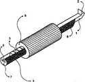
图1是本发明的深度计系统的优选实施例的透视图;Figure 1 is a perspective view of a preferred embodiment of the depth gauge system of the present invention;
图2是图1所示深度计系统的分解透视图;Figure 2 is an exploded perspective view of the depth gauge system shown in Figure 1;
图3是在使用图1所示深度计系统的优选外科技术中的第一步的侧视图;Figure 3 is a side view of a first step in a preferred surgical technique using the depth gauge system shown in Figure 1;
图4是在使用图1所示深度计系统的优选外科技术中的第二步的侧视图;Figure 4 is a side view of a second step in the preferred surgical technique using the depth gauge system shown in Figure 1;
图5是在使用图1所示深度计系统的优选外科技术中的第三步的侧视图,以及;Figure 5 is a side view of a third step in the preferred surgical technique using the depth gauge system shown in Figure 1, and;
图6是在使用图1所示深度计系统的优选外科技术中的第四步的侧视图。6 is a side view of a fourth step in the preferred surgical technique using the depth gauge system shown in FIG. 1 .
具体实施方式Detailed ways
在下文中将参照图1-2来描述本发明的优选实施例。Hereinafter, preferred embodiments of the present invention will be described with reference to FIGS. 1-2.
图1显示了本发明的深度测量工具的一个优选实施例。探针1与带槽的插入物4中的槽5接合,并且能够相对于带槽的插入物4沿探针1的纵向轴线自由地滑动。管状外壳8可滑动地安装在探针1和带槽的插入物4上。Figure 1 shows a preferred embodiment of the depth measurement tool of the present invention. The probe 1 engages with the
图2清楚地示出了分解的系统,其中显示了其三个组件:探针1、带槽的插入物4和管状外壳8。探针具有位于其远端的支座2,以及位于其近端的刻度3。带槽的插入物4包括用来容纳探针1的槽、近端7,以及设计成避免与待测孔10的近边相撞的锥形远端6。管状外壳8的大小设计成使得可在其中容纳带槽的插入物4和探针1。FIG. 2 clearly shows the disassembled system, showing its three components: probe 1 , slotted
在另一个优选的实施例中,探针1包括位于其近端上的阳螺纹,其配置成能够接收带阴螺纹的装置,以便能用该带阴螺纹的装置来将管状外壳8推动到近端的骨头壁上,同时允许刻度3标示待瞄准钉的准确位置。In another preferred embodiment, the probe 1 includes a male thread on its proximal end configured to receive a female threaded device so that the female threaded device can be used to push the
在下文中将参照图3-6来说明根据本发明的一个优选实施例的深度测量的优选方法。A preferred method of depth measurement according to a preferred embodiment of the present invention will be described below with reference to FIGS. 3-6 .
如图3最佳地示出,当收回带槽的插入物4时,探针1能够容易地插入到骨孔9中并从中穿过,同时管状外壳8位于后面。As best shown in Figure 3, when the
然后,如图4清楚地示出,带槽的插入物4向着其最终的目的地滑动,从而向着上骨孔壁10向上推动探针1。带槽插入物4的锥形远端6阻止了带槽插入物4靠在骨孔壁10上。Then, as best shown in FIG. 4 , the
当探针1和带槽插入物4相对于骨9一起收回时,如图5所示,探针1的支座2牢固地接合在远端的骨壁上。When the stylet 1 and slotted
图6显示了测量过程的最后步骤。管状外壳8被向前推动直到其靠在近端的骨壁上,从而允许在探针1的后端处的刻度3上准确地读出孔的深度。Figure 6 shows the final steps of the measurement process. The
虽然已经表示和描述了本发明的优选实施例,但是应当理解,在不脱离如附加的权利要求限定的本发明的精神和范围的情况下,本技术领域的技术人员能够设计出变型以及修改。While there has been shown and described preferred embodiments of the present invention, it should be understood that variations and modifications can be devised by those skilled in the art without departing from the spirit and scope of the invention as defined in the appended claims.
Claims (18)
Applications Claiming Priority (3)
| Application Number | Priority Date | Filing Date | Title |
|---|---|---|---|
| US11/248,525US7559150B2 (en) | 2005-10-13 | 2005-10-13 | Depth gauge |
| US11/248,525 | 2005-10-13 | ||
| PCT/US2006/040146WO2007047466A1 (en) | 2005-10-13 | 2006-10-13 | Depth gauge |
Related Child Applications (1)
| Application Number | Title | Priority Date | Filing Date |
|---|---|---|---|
| CN2010101345824ADivisionCN101874737B (en) | 2005-10-13 | 2006-10-13 | Depth gauge |
Publications (2)
| Publication Number | Publication Date |
|---|---|
| CN101283233Atrue CN101283233A (en) | 2008-10-08 |
| CN101283233B CN101283233B (en) | 2010-06-02 |
Family
ID=37686104
Family Applications (2)
| Application Number | Title | Priority Date | Filing Date |
|---|---|---|---|
| CN2006800377815AExpired - Fee RelatedCN101283233B (en) | 2005-10-13 | 2006-10-13 | Depth gauge |
| CN2010101345824AExpired - Fee RelatedCN101874737B (en) | 2005-10-13 | 2006-10-13 | Depth gauge |
Family Applications After (1)
| Application Number | Title | Priority Date | Filing Date |
|---|---|---|---|
| CN2010101345824AExpired - Fee RelatedCN101874737B (en) | 2005-10-13 | 2006-10-13 | Depth gauge |
Country Status (14)
| Country | Link |
|---|---|
| US (2) | US7559150B2 (en) |
| EP (1) | EP1938039B1 (en) |
| JP (1) | JP4954214B2 (en) |
| KR (1) | KR101277765B1 (en) |
| CN (2) | CN101283233B (en) |
| AT (1) | ATE438076T1 (en) |
| AU (1) | AU2006304275A1 (en) |
| BR (1) | BRPI0617320B1 (en) |
| CA (1) | CA2625740C (en) |
| DE (1) | DE602006008168D1 (en) |
| ES (1) | ES2327357T3 (en) |
| PL (1) | PL1938039T3 (en) |
| WO (1) | WO2007047466A1 (en) |
| ZA (1) | ZA200803228B (en) |
Cited By (5)
| Publication number | Priority date | Publication date | Assignee | Title |
|---|---|---|---|---|
| CN101749999B (en)* | 2010-01-07 | 2012-04-18 | 沈阳飞机工业(集团)有限公司 | Locating device of bore gauge for measuring diameter size of inner bore in specific depth |
| CN103245270A (en)* | 2013-05-20 | 2013-08-14 | 山东太古飞机工程有限公司 | Scale for measuring thickness of hole wall of plane |
| CN109141176A (en)* | 2018-09-06 | 2019-01-04 | 国营芜湖机械厂 | A kind of length of straigh line detection device and its detection method for aircraft conduit |
| CN110121294A (en)* | 2016-11-03 | 2019-08-13 | 爱知外科股份有限公司 | Surgical depth instrument with neuromonitoring capabilities |
| CN113280711A (en)* | 2021-06-22 | 2021-08-20 | 上海博进凯利泰医疗科技有限公司 | Capsular reconstruction measuring tool and capsular measuring method |
Families Citing this family (32)
| Publication number | Priority date | Publication date | Assignee | Title |
|---|---|---|---|---|
| US7434325B2 (en)* | 2004-07-26 | 2008-10-14 | Warsaw Orthopedic, Inc. | Systems and methods for determining optimal retractor length in minimally invasive procedures |
| US20080287959A1 (en)* | 2005-09-26 | 2008-11-20 | Archus Orthopedics, Inc. | Measurement and trialing system and methods for orthopedic device component selection |
| US7559150B2 (en)* | 2005-10-13 | 2009-07-14 | Synthes Usa, Llc | Depth gauge |
| US7448143B2 (en)* | 2006-12-01 | 2008-11-11 | General Electric Company | Method and system for inserting a probe |
| US20090005786A1 (en)* | 2007-06-28 | 2009-01-01 | Stryker Trauma Gmbh | Bone hole measuring device |
| US7644508B1 (en)* | 2008-05-08 | 2010-01-12 | Andrew Schmitz | Retrofit recessed lighting installation tool |
| US7845091B2 (en)* | 2008-08-07 | 2010-12-07 | Clark Charles L | Brake pad measuring tool and method of using the same |
| US20110046632A1 (en)* | 2009-06-02 | 2011-02-24 | Felix Quevedo | Medical Tool And Method For Forming Holes |
| WO2010147577A1 (en)* | 2009-06-15 | 2010-12-23 | Societe De Technologie Michelin | Tire carcass cable depth gauge and method of use |
| US20110000344A1 (en)* | 2009-07-01 | 2011-01-06 | Jeremy Summers | Depth gauge and adjustment tool for adjustable fastener receptacles and method |
| US8233239B1 (en) | 2010-12-15 | 2012-07-31 | Western Digital Technologies, Inc. | Disk drive head stack assembly having first and second swage bosses with different inner lip profiles |
| US8728088B2 (en)* | 2011-09-16 | 2014-05-20 | Smith & Nephew, Inc. | Flexible depth probe |
| US8523875B2 (en)* | 2011-10-11 | 2013-09-03 | Smith & Nephew, Inc. | Graft caliper marking device |
| KR102114643B1 (en) | 2011-12-30 | 2020-05-27 | 신세스 게엠바하 | Single patient use depth gauge |
| US9949796B2 (en) | 2011-12-30 | 2018-04-24 | DePuy Synthes Products, Inc. | Round depth gauge |
| US9341522B2 (en) | 2013-05-01 | 2016-05-17 | Rosemount Inc. | Spring-loaded temperature sensor |
| US9243881B2 (en)* | 2014-05-29 | 2016-01-26 | Smith & Nephew, Inc. | Retrograde reamer depth tub gage |
| DE102015101650B4 (en)* | 2015-02-05 | 2018-05-03 | Aesculap Ag | Detection and display device for detecting and indicating the presence or absence of a stabilizing rod in the tulip head of a pedicle screw, and spinal stabilization system with such a detection and display device |
| CN204797977U (en)* | 2015-06-30 | 2015-11-25 | 深圳雅涵医疗美容门诊部 | Bone positioner is cut at lower jaw angle |
| KR101706893B1 (en)* | 2016-07-07 | 2017-02-14 | 인제대학교 산학협력단 | Depth gauge for medical care |
| US10330453B2 (en)* | 2017-03-29 | 2019-06-25 | Lockheed Martin Corporation | Wireless fastener grip gauge |
| US20180292194A1 (en)* | 2017-04-06 | 2018-10-11 | Michael MERTO | Kit and method for measuring a pipe coupling groove |
| US10792080B2 (en) | 2017-06-14 | 2020-10-06 | Edge Surgical, Inc. | Devices for minimally invasive procedures |
| FR3068270A1 (en)* | 2017-07-03 | 2019-01-04 | Psa Automobiles Sa | DEPTH DEPTH TOOLING OF STAMPING DEPTH IN A STAMPING PRESS |
| US11992227B2 (en) | 2018-03-05 | 2024-05-28 | Edge Surgical, Inc. | Handheld devices for use in medical procedures |
| AU2019231188B2 (en) | 2018-03-05 | 2021-02-11 | Edge Surgical, Inc. | Handheld devices for use in medical procedures |
| CN108759621A (en)* | 2018-07-02 | 2018-11-06 | 中信戴卡股份有限公司 | A kind of right angle touch rule |
| EP3937807B1 (en)* | 2019-03-11 | 2025-01-08 | EDGe Surgical, Inc. | Surgical depth instrument |
| WO2020185508A1 (en)* | 2019-03-11 | 2020-09-17 | Edge Surgical, Inc. | Surgical depth instrument |
| CN111658165B (en)* | 2020-06-30 | 2025-02-11 | 常州大章医疗器械有限公司 | A pistol-style depth gauge |
| CN113109599B (en)* | 2021-03-30 | 2024-01-19 | 渭南木王智能科技股份有限公司 | Rolling groove jig for precise fine probe |
| CN114674207B (en)* | 2022-04-28 | 2024-04-12 | 马鞍山钢铁股份有限公司 | Bottom surface flatness measuring device and method for flat-bottom blind hole |
Family Cites Families (10)
| Publication number | Priority date | Publication date | Assignee | Title |
|---|---|---|---|---|
| US5013318A (en) | 1990-07-31 | 1991-05-07 | Special Devices Incorporated | Medical instrument for measuring depth of fastener hold in bone |
| DE20011156U1 (en) | 2000-06-24 | 2000-12-21 | Ferber, Ottfried, Dr.med., 98617 Herpf | Sensor for drill channel lengths |
| US6524259B2 (en)* | 2001-06-08 | 2003-02-25 | Cervilenz, Inc. | Devices and methods for cervix measurement |
| MXPA04007703A (en)* | 2002-02-07 | 2004-11-10 | Synthes Ag | Device for measuring length and depth which can be used in surgery. |
| JP3565834B2 (en)* | 2002-04-26 | 2004-09-15 | 有限会社アイデーエム | Infection control device for root canal length measurement |
| US7340309B2 (en)* | 2002-12-16 | 2008-03-04 | Meagan Medical, Inc. | Method and apparatus for controlling the depth of percutaneous applications |
| CN2719254Y (en)* | 2004-08-27 | 2005-08-24 | 刘伟忠 | Bone hole detector |
| US7165336B2 (en)* | 2005-03-16 | 2007-01-23 | Eidosmed Llc | Surgical depth instrument |
| US7559150B2 (en)* | 2005-10-13 | 2009-07-14 | Synthes Usa, Llc | Depth gauge |
| EP1929945A3 (en)* | 2006-12-07 | 2009-01-14 | Arthrex, Inc. | Measuring device |
- 2005
- 2005-10-13USUS11/248,525patent/US7559150B2/enactiveActive
- 2006
- 2006-10-13CNCN2006800377815Apatent/CN101283233B/ennot_activeExpired - Fee Related
- 2006-10-13ATAT06816899Tpatent/ATE438076T1/enactive
- 2006-10-13EPEP06816899Apatent/EP1938039B1/ennot_activeNot-in-force
- 2006-10-13KRKR1020087009331Apatent/KR101277765B1/ennot_activeExpired - Fee Related
- 2006-10-13WOPCT/US2006/040146patent/WO2007047466A1/enactiveApplication Filing
- 2006-10-13PLPL06816899Tpatent/PL1938039T3/enunknown
- 2006-10-13BRBRPI0617320-9Apatent/BRPI0617320B1/ennot_activeIP Right Cessation
- 2006-10-13DEDE602006008168Tpatent/DE602006008168D1/enactiveActive
- 2006-10-13ESES06816899Tpatent/ES2327357T3/enactiveActive
- 2006-10-13JPJP2008535722Apatent/JP4954214B2/ennot_activeExpired - Fee Related
- 2006-10-13ZAZA200803228Apatent/ZA200803228B/enunknown
- 2006-10-13CNCN2010101345824Apatent/CN101874737B/ennot_activeExpired - Fee Related
- 2006-10-13AUAU2006304275Apatent/AU2006304275A1/ennot_activeAbandoned
- 2006-10-13CACA2625740Apatent/CA2625740C/ennot_activeExpired - Fee Related
- 2009
- 2009-07-13USUS12/501,934patent/US7823296B2/ennot_activeExpired - Lifetime
Cited By (6)
| Publication number | Priority date | Publication date | Assignee | Title |
|---|---|---|---|---|
| CN101749999B (en)* | 2010-01-07 | 2012-04-18 | 沈阳飞机工业(集团)有限公司 | Locating device of bore gauge for measuring diameter size of inner bore in specific depth |
| CN103245270A (en)* | 2013-05-20 | 2013-08-14 | 山东太古飞机工程有限公司 | Scale for measuring thickness of hole wall of plane |
| CN103245270B (en)* | 2013-05-20 | 2016-04-06 | 山东太古飞机工程有限公司 | Aircraft pore wall thickness dip stick |
| CN110121294A (en)* | 2016-11-03 | 2019-08-13 | 爱知外科股份有限公司 | Surgical depth instrument with neuromonitoring capabilities |
| CN109141176A (en)* | 2018-09-06 | 2019-01-04 | 国营芜湖机械厂 | A kind of length of straigh line detection device and its detection method for aircraft conduit |
| CN113280711A (en)* | 2021-06-22 | 2021-08-20 | 上海博进凯利泰医疗科技有限公司 | Capsular reconstruction measuring tool and capsular measuring method |
Also Published As
| Publication number | Publication date |
|---|---|
| KR101277765B1 (en) | 2013-06-24 |
| JP4954214B2 (en) | 2012-06-13 |
| ES2327357T3 (en) | 2009-10-28 |
| CN101874737B (en) | 2012-04-25 |
| DE602006008168D1 (en) | 2009-09-10 |
| JP2009511202A (en) | 2009-03-19 |
| BRPI0617320B1 (en) | 2018-07-03 |
| CA2625740A1 (en) | 2007-04-26 |
| BRPI0617320A2 (en) | 2011-07-19 |
| EP1938039A1 (en) | 2008-07-02 |
| WO2007047466A1 (en) | 2007-04-26 |
| US20090272001A1 (en) | 2009-11-05 |
| US20070088366A1 (en) | 2007-04-19 |
| PL1938039T3 (en) | 2009-11-30 |
| ZA200803228B (en) | 2009-09-30 |
| CN101283233B (en) | 2010-06-02 |
| AU2006304275A1 (en) | 2007-04-26 |
| ATE438076T1 (en) | 2009-08-15 |
| US7823296B2 (en) | 2010-11-02 |
| CA2625740C (en) | 2014-12-16 |
| EP1938039B1 (en) | 2009-07-29 |
| KR20080056732A (en) | 2008-06-23 |
| CN101874737A (en) | 2010-11-03 |
| US7559150B2 (en) | 2009-07-14 |
Similar Documents
| Publication | Publication Date | Title |
|---|---|---|
| CN101283233B (en) | Depth gauge | |
| US5176516A (en) | Instrument for measuring a remaining alveolar bone | |
| US10743958B2 (en) | Round depth gauge | |
| US9603565B2 (en) | Single patient use depth gauge | |
| JPH09503413A (en) | Gauge for bone marrow lumen |
Legal Events
| Date | Code | Title | Description |
|---|---|---|---|
| C06 | Publication | ||
| PB01 | Publication | ||
| C10 | Entry into substantive examination | ||
| SE01 | Entry into force of request for substantive examination | ||
| C14 | Grant of patent or utility model | ||
| GR01 | Patent grant | ||
| CF01 | Termination of patent right due to non-payment of annual fee | ||
| CF01 | Termination of patent right due to non-payment of annual fee | Granted publication date:20100602 Termination date:20201013 |