CN101282573A - Wireless communication system for automatically generating a received signal strength profile - Google Patents
Wireless communication system for automatically generating a received signal strength profileDownload PDFInfo
- Publication number
- CN101282573A CN101282573ACNA2007100920418ACN200710092041ACN101282573ACN 101282573 ACN101282573 ACN 101282573ACN A2007100920418 ACNA2007100920418 ACN A2007100920418ACN 200710092041 ACN200710092041 ACN 200710092041ACN 101282573 ACN101282573 ACN 101282573A
- Authority
- CN
- China
- Prior art keywords
- signal strength
- received signal
- mobile device
- wireless communication
- communication system
- Prior art date
- Legal status (The legal status is an assumption and is not a legal conclusion. Google has not performed a legal analysis and makes no representation as to the accuracy of the status listed.)
- Granted
Links
- 238000004891communicationMethods0.000titleclaimsabstractdescription41
- 238000010586diagramMethods0.000claimsdescription15
- 238000000034methodMethods0.000claimsdescription9
- 238000005516engineering processMethods0.000description3
- 230000007613environmental effectEffects0.000description2
- 239000004165Methyl ester of fatty acidsSubstances0.000description1
- 230000005611electricityEffects0.000description1
Images


Landscapes
- Position Fixing By Use Of Radio Waves (AREA)
- Mobile Radio Communication Systems (AREA)
Abstract
Description
Translated fromChinese技术领域technical field
本发明涉及一种无线通信系统,且特别涉及一种用于自动产生接收信号强度分布图的无线通信系统。The present invention relates to a wireless communication system, and in particular to a wireless communication system for automatically generating distribution diagrams of received signal strength.
背景技术Background technique
近年来,无线通信定位技术发展相当蓬勃,该项技术的应用范围也日渐广泛。举例而言,定位技术可应用于导航系统、使用者所在位置信息管理、移动紧急定位系统(Mobile Emergency Positioning)(例如美国手机对于E-911法规的相关定位要求)、物流管理、车队调动等。In recent years, the development of wireless communication positioning technology is quite vigorous, and the application range of this technology is also becoming wider and wider. For example, positioning technology can be applied to navigation systems, user location information management, mobile emergency positioning system (Mobile Emergency Positioning) (such as the relevant positioning requirements of US mobile phones for E-911 regulations), logistics management, fleet mobilization, etc.
一般无线通信系统会预先建立接收信号强度分布图,用于定位移动装置。目前,建立接收信号强度分布图通常采用信号特征法(Fingerprint)。使用信号特征法建立接收信号强度分布图时,需要有整个定位环境的地图,并且要在整个定位环境中利用可检测信号的电子装置取样信号特征。当定位环境相当大时,利用信号特征法建立接收信号强度分布图就需要花费非常多的时间与成本。此外,当定位环境发生改变,若原先建立的接收信号强度分布图没有更新时,定位就会产生误差。A general wireless communication system will pre-establish a distribution map of received signal strength for locating the mobile device. At present, a signal characteristic method (Fingerprint) is usually used to establish a received signal strength distribution map. When using the signal characteristic method to establish a received signal strength distribution map, a map of the entire positioning environment is required, and an electronic device that can detect signals must be used to sample signal characteristics in the entire positioning environment. When the positioning environment is quite large, it takes a lot of time and cost to use the signal characteristic method to establish the distribution map of received signal strength. In addition, when the positioning environment changes, if the previously established received signal strength distribution map is not updated, positioning errors will occur.
因此,本发明的范畴在于提供一种可自动产生接收信号强度分布图的无线通信系统,以解决上述问题。Therefore, the scope of the present invention is to provide a wireless communication system that can automatically generate a received signal strength distribution map to solve the above problems.
发明内容Contents of the invention
本发明的范畴之一在于提供一种无线通信系统(Wirelesscommunication system),用于自动产生一接收信号强度分布图。One of the scopes of the present invention is to provide a wireless communication system (Wireless communication system) for automatically generating a received signal strength distribution map.
根据一较佳具体实施例,本发明的无线通信系统包含多个第一移动装置、第二移动装置以及系统端。系统端与第二移动装置配合,以决定每一第一移动装置的坐标。当第一移动装置接收来自系统端的信号时,第一移动装置会测出对应的接收信号强度。系统端或第二移动装置可根据每一第一移动装置的坐标以及接收信号强度,自动产生接收信号强度分布图。According to a preferred embodiment, the wireless communication system of the present invention includes a plurality of first mobile devices, a second mobile device and a system end. The system side cooperates with the second mobile device to determine the coordinates of each first mobile device. When the first mobile device receives a signal from the system end, the first mobile device measures the corresponding received signal strength. The system end or the second mobile device can automatically generate a received signal strength distribution map according to the coordinates and received signal strength of each first mobile device.
因此,本发明的无线通信系统利用多个移动装置的坐标以及所述移动装置的接收信号强度,自动产生接收信号强度分布图。藉此,移动装置可藉由接收信号强度分布图快速地决定移动装置本身的坐标。Therefore, the wireless communication system of the present invention utilizes the coordinates of a plurality of mobile devices and the received signal strengths of the mobile devices to automatically generate a distribution map of received signal strengths. In this way, the mobile device can quickly determine the coordinates of the mobile device itself according to the received signal strength distribution graph.
关于本发明的优点与精神可以藉由以下的发明详述及附图得到进一步的了解。The advantages and spirit of the present invention can be further understood through the following detailed description of the invention and the accompanying drawings.
附图说明Description of drawings
图1示出了根据本发明一较佳具体实施例的无线通信系统的功能方块图;Fig. 1 shows a functional block diagram of a wireless communication system according to a preferred embodiment of the present invention;
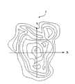
图2示出了图1的无线通信系统自动产生的接收信号强度分布图的示意图;Fig. 2 shows a schematic diagram of a received signal strength distribution diagram automatically generated by the wireless communication system of Fig. 1;
图3示出了图1的无线通信系统定位第一移动装置的示意图;以及FIG. 3 shows a schematic diagram of positioning the first mobile device by the wireless communication system of FIG. 1; and
图4示出了根据本发明另一较佳具体实施例利用图1的无线通信系统定位第一移动装置的示意图。FIG. 4 shows a schematic diagram of using the wireless communication system in FIG. 1 to locate a first mobile device according to another preferred embodiment of the present invention.
附图符号说明Description of reference symbols
1:无线通信系统 10:第一移动装置1: Wireless communication system 10: The first mobile device
12:第二移动装置 14:系统端12: Second mobile device 14: System side
2:坐标系统 θ1-θn:角度2: Coordinate system θ1-θn: angle
LA1-LAn、LB1-LBn:距离 CB1-CBn、C1-Cn:坐标LA1-LAn, LB1-LBn: distance CB1-CBn, C1-Cn: coordinates
3:接收信号强度分布图3: Received signal strength distribution map
具体实施方式Detailed ways
请参阅图1以及图2,图1示出了根据本发明一较佳具体实施例的无线通信系统1的功能方块图,图2示出了图1的无线通信系统1所自动产生的接收信号强度分布图3的示意图。如图2所示,接收信号强度分布图3是坐标对应接收信号强度的分布图,用于根据接收信号强度决定坐标。在此实施例中,无线通信系统1用于自动产生接收信号强度分布图3。Please refer to FIG. 1 and FIG. 2, FIG. 1 shows a functional block diagram of a wireless communication system 1 according to a preferred embodiment of the present invention, and FIG. 2 shows a received signal automatically generated by the wireless communication system 1 of FIG. 1 Figure 3. Schematic representation of the intensity distribution. As shown in FIG. 2 , the distribution of received signal strengths in FIG. 3 is a distribution diagram of coordinates corresponding to received signal strengths, which is used to determine coordinates according to received signal strengths. In this embodiment, the wireless communication system 1 is used to automatically generate the received signal
如图1所示,无线通信系统1包含多个第一移动装置10、第二移动装置12以及系统端14。其中,系统端14可为基站(Bases tation),但不以此为限。第一移动装置10以及第二移动装置12分别可为笔记本型计算机、个人数字助理(PDA)、导航装置、移动电话或其它类似移动装置。系统端14可具有到达时间(Time of arrival,TOA)算法、到达时间差(Time differentce ofarrival,TDOA)算法、到达方向(Direction of arrival,DOA)算法、接收信号强度(RSS)算法以及其它类似无线定位算法的至少其中之一。第二移动装置12可具有TOA算法、TDOA算法、RSS算法以及其它类似无线定位算法的至少其中之一。当第一移动装置10接收来自系统端14的信号,第一移动装置10可测出对应的接收信号强度。As shown in FIG. 1 , the wireless communication system 1 includes a plurality of first
请参阅图3,图3示出了图1的无线通信系统1定位第一移动装置10的示意图。在此实施例中,系统端14与第二移动装置12配合,以决定每一第一移动装置10的坐标。如图3所示,系统端14预先建立坐标系统2,其中,系统端14位于坐标系统2的原点,且坐标系统2具有X轴以及Y轴。接着,系统端14可利用TOA算法、TDOA算法或RSS算法决定系统端14与每一个第一移动装置10之间的距离LA1-LAn,并且利用DOA算法决定每一个第一移动装置10对应X轴或Y轴的角度θ1-θn。在此实施例中,第二移动装置12的坐标CB1为已知。第二移动装置12可利用其所具有的TOA算法、TDOA算法或RSS算法决定第二移动装置12与每一个第一移动装置10的距离LB1-LBn。系统端14可根据系统端14与每一个第一移动装置10之间的距离LA1-LAn、每一个第一移动装置10对应X轴或Y轴的角度θ1-θn以及第二移动装置12与每一个第一移动装置10之间的距离LB1-LBn,决定每一个第一移动装置10在坐标系统2上的坐标C1-Cn。藉此,可以得到每一个第一移动装置10的坐标C1-Cn。需注意的是,第二移动装置12的功能在于配合系统端14,以更准确地定位第一移动装置10。此外,第二移动装置12的数量可以大于1,以增加定位的效率及准确度。Please refer to FIG. 3 , which shows a schematic diagram of positioning the first
当每一个第一移动装置10接收来自系统端14的信号,每一个第一移动装置10会测出对应的接收信号强度。接着,每一个第一移动装置10可将其对应的接收信号强度传送至系统端14或第二移动装置12。因此,系统端14或第二移动装置12可根据第一移动装置10的坐标C1-Cn以及第一移动装置10的接收信号强度,自动产生如图2所示的接收信号强度分布图3。When each first
请参阅图4,图4示出了根据本发明另一较佳具体实施例利用图1的无线通信系统1定位第一移动装置10的示意图。在此实施例中,无线通信系统1具有三个第二移动装置12,每一第二移动装置12可分别具有TOA算法、TDOA算法、RSS算法以及其它类似无线定位算法的至少其中之一。第二移动装置12的坐标CB1-CB3为已知。如图4所示,三个第二移动装置12可利用其所具有的TOA算法、TDOA算法或RSS算法,并且利用三角定位算法相互配合,以决定第一移动装置10的坐标C1-Cn。三角定位算法为现有技艺之人可轻易达成,在此不再赘述。在实际应用时,第二移动装置12的数量可以大于3,以增加定位的效率及准确度。Please refer to FIG. 4 , which shows a schematic diagram of locating the first
当每一个第一移动装置10接收来自系统端14的信号,每一个第一移动装置10会测出对应的第一接收信号强度。接着,每一个第一移动装置10可将其对应的接收信号强度传送至系统端14或第二移动装置12。因此,系统端14或第二移动装置12可根据第一移动装置10的坐标C1-Cn以及第一移动装置10的接收信号强度,自动产生如图2所示的接收信号强度分布图3。When each first
接收信号强度分布图3用于定位目标移动装置(未显示)。当目标移动装置(未显示)接收来自系统端14的信号,目标移动装置(未显示)会测出对应的接收信号强度。接着,目标移动装置(未显示)可根据其接收信号强度以及接收信号强度分布图3,决定目标移动装置(未显示)本身的坐标。值得注意的是,当第一移动装置10的数量越多,利用接收信号强度分布图3的定位方法就越准确。此外,当信号强度分布图3不足以准确地决定目标移动装置(未显示)的坐标时,可配合系统端14及/或第二移动装置12所具有的无线定位算法,以更加准确地决定目标移动装置(未显示)的坐标。Received
在实际应用时,当接收信号强度分布图3的目标坐标(未显示)缺少对应的接收信号强度时,系统端14或第二移动装置12可利用最小平方法,根据接收信号强度分布图3已有的坐标以及对应的接收信号强度,分别计算目标坐标的X坐标值所对应的接收信号强度以及Y坐标值所对应的接收信号强度。接着,将目标坐标的X坐标值所对应的接收信号强度以及Y坐标值所对应的接收信号强度两者平均,得出平均接收信号强度,以作为目标坐标的接收信号强度。当第一移动装置10移动到目标坐标时,再以实际的接收信号强度取代利用最小平方法计算出的接收信号强度。In actual application, when the target coordinates (not shown) of the received signal strength distribution in Figure 3 lack the corresponding received signal strength, the
在实际应用时,当无线通信系统1加入新的第一移动装置10,或第一移动装置10移动到不同的坐标时,无线通信系统1都可以藉此更新接收信号强度分布图3,进而使定位更准确,亦可不受环境改变的影响。此外,当接收信号强度分布图3已具有足够多的坐标以及接收信号强度作为样本时,可以选择性地使系统端14及/或第二移动装置12的无线定位功能暂时停止,以节省电力成本。举例而言,第二移动装置12可每隔一段时间,根据信号强度分布图3在第二移动装置12的可定位范围内的完整性,选择性地使能(Enable)或禁止(Disable)第二移动装置12的无线定位功能,以节省电力成本。第二移动装置12的可定位范围取决于第二移动装置12所采用的无线标准。举例而言,超宽频(UWB)以及蓝牙(Bluetooth)的定位范围为10公尺;802.11b/g局域网络的定位范围为50-100公尺;须注意的是,第二移动装置12所采用的无线标准并不以此为限。In actual application, when the wireless communication system 1 adds a new first
相较于现有技术,因此,本发明的无线通信系统是利用多个移动装置的坐标以及所述移动装置的接收信号强度,自动产生接收信号强度分布图。藉此,移动装置可藉由信号强度分布图快速地决定移动装置本身的坐标。由于移动装置的数量日渐增长,因此本发明的无线通信系统在建立接收信号强度分布图时将更有效率,花费的成本亦较低。此外,本发明的无线通信系统可藉由更新接收信号强度分布图,使定位更准确,亦更不受环境改变的影响。Compared with the prior art, therefore, the wireless communication system of the present invention utilizes the coordinates of multiple mobile devices and the received signal strengths of the mobile devices to automatically generate a distribution map of received signal strengths. In this way, the mobile device can quickly determine the coordinates of the mobile device itself through the signal strength distribution map. Since the number of mobile devices is increasing day by day, the wireless communication system of the present invention is more efficient and less costly in establishing the distribution map of received signal strength. In addition, the wireless communication system of the present invention can make positioning more accurate by updating the received signal strength distribution map, and is also less affected by environmental changes.
藉由以上较佳具体实施例的详述,是希望能更加清楚描述本发明的特征与精神,而并非以上述所揭露的较佳具体实施例来对本发明的范畴加以限制。相反地,其目的是希望能涵盖各种改变及具相等性的安排于本发明所欲申请的专利范围的范畴内。因此,本发明所申请的专利范围的范畴应该根据上述的说明作最宽广的解释,以致使其涵盖所有可能的改变以及具相等性的安排。Through the above detailed description of the preferred embodiments, it is hoped that the characteristics and spirit of the present invention can be described more clearly, and the scope of the present invention is not limited by the preferred embodiments disclosed above. On the contrary, the intention is to cover various changes and equivalent arrangements within the scope of the claimed patent scope of the present invention. Therefore, the scope of the claimed scope of the present invention should be interpreted in the broadest way based on the above description, so as to cover all possible changes and equivalent arrangements.
Claims (13)
Translated fromChinesePriority Applications (1)
| Application Number | Priority Date | Filing Date | Title |
|---|---|---|---|
| CN2007100920418ACN101282573B (en) | 2007-04-04 | 2007-04-04 | Wireless Communication System for Automatically Generating Received Signal Strength Profiles |
Applications Claiming Priority (1)
| Application Number | Priority Date | Filing Date | Title |
|---|---|---|---|
| CN2007100920418ACN101282573B (en) | 2007-04-04 | 2007-04-04 | Wireless Communication System for Automatically Generating Received Signal Strength Profiles |
Publications (2)
| Publication Number | Publication Date |
|---|---|
| CN101282573Atrue CN101282573A (en) | 2008-10-08 |
| CN101282573B CN101282573B (en) | 2011-09-14 |
Family
ID=40014794
Family Applications (1)
| Application Number | Title | Priority Date | Filing Date |
|---|---|---|---|
| CN2007100920418AExpired - Fee RelatedCN101282573B (en) | 2007-04-04 | 2007-04-04 | Wireless Communication System for Automatically Generating Received Signal Strength Profiles |
Country Status (1)
| Country | Link |
|---|---|
| CN (1) | CN101282573B (en) |
Cited By (3)
| Publication number | Priority date | Publication date | Assignee | Title |
|---|---|---|---|---|
| CN102164405A (en)* | 2010-12-17 | 2011-08-24 | 东软集团股份有限公司 | Method and system for quickly positioning |
| CN103179505A (en)* | 2011-12-26 | 2013-06-26 | 宇龙计算机通信科技(深圳)有限公司 | Data acquisition method, terminal and server |
| CN103228040A (en)* | 2012-01-31 | 2013-07-31 | 国际商业机器公司 | Indoor electronic map generating method and system, and indoor target positioning method and system |
Families Citing this family (1)
| Publication number | Priority date | Publication date | Assignee | Title |
|---|---|---|---|---|
| TWI544822B (en) | 2014-12-17 | 2016-08-01 | 緯創資通股份有限公司 | Signal strength distribution establishing method and wireless positioning system |
- 2007
- 2007-04-04CNCN2007100920418Apatent/CN101282573B/ennot_activeExpired - Fee Related
Cited By (4)
| Publication number | Priority date | Publication date | Assignee | Title |
|---|---|---|---|---|
| CN102164405A (en)* | 2010-12-17 | 2011-08-24 | 东软集团股份有限公司 | Method and system for quickly positioning |
| CN102164405B (en)* | 2010-12-17 | 2013-10-16 | 东软集团股份有限公司 | Method and system for quickly positioning |
| CN103179505A (en)* | 2011-12-26 | 2013-06-26 | 宇龙计算机通信科技(深圳)有限公司 | Data acquisition method, terminal and server |
| CN103228040A (en)* | 2012-01-31 | 2013-07-31 | 国际商业机器公司 | Indoor electronic map generating method and system, and indoor target positioning method and system |
Also Published As
| Publication number | Publication date |
|---|---|
| CN101282573B (en) | 2011-09-14 |
Similar Documents
| Publication | Publication Date | Title |
|---|---|---|
| CN102404843B (en) | Positioning method and wireless communication system | |
| CN104038901B (en) | Indoor positioning method for reducing fingerprint data acquisition workload | |
| CN103119998A (en) | Method and apparatus for identifying local beacon systems | |
| CN101808400A (en) | The system and method that is used for efficiently populating access point database | |
| JP7461483B2 (en) | Positioning method and communication equipment | |
| CN101155371A (en) | Mobile communication terminal and method for receiving location information service | |
| CN108513353B (en) | Method for realizing mobile robot positioning based on double beacon nodes | |
| CN111372181A (en) | Indoor positioning method and device based on Bluetooth and storage medium | |
| CN101282573B (en) | Wireless Communication System for Automatically Generating Received Signal Strength Profiles | |
| CN107645702A (en) | position calibration method, device and system | |
| CN103069778A (en) | Method for location | |
| CN113596727A (en) | Mobile phone positioning and navigation system and method applied to mine | |
| CN112484716A (en) | Indoor positioning navigation system based on 5G indoor distribution system | |
| US8103286B2 (en) | Wireless communication system for automatically generating a received signal strength distribution map | |
| US20120088519A1 (en) | Mobile device for low power identification of its position and a method therefore | |
| KR20200079733A (en) | A method and apparatus for location estimation of terminal in a wireless communication system | |
| CN100486355C (en) | Method and apparatus for realizing mobile station positioning in radio communication system | |
| CN108605310B (en) | Method and device for adjusting positioning period | |
| CN1940590B (en) | Positioning method and system | |
| CN108540926B (en) | Wireless signal fingerprint construction method and device | |
| CN111918389A (en) | Outdoor positioning method and device based on unmanned aerial vehicle gateway | |
| WO2018184263A1 (en) | Positioning method and device | |
| CN105979581A (en) | Indoor positioning method based on power difference | |
| Pei et al. | An indoor positioning algorithm based on received signal strength of WLAN | |
| CN101238748A (en) | Method for positioning mobile terminal |
Legal Events
| Date | Code | Title | Description |
|---|---|---|---|
| C06 | Publication | ||
| PB01 | Publication | ||
| C10 | Entry into substantive examination | ||
| SE01 | Entry into force of request for substantive examination | ||
| C14 | Grant of patent or utility model | ||
| GR01 | Patent grant | ||
| CF01 | Termination of patent right due to non-payment of annual fee | ||
| CF01 | Termination of patent right due to non-payment of annual fee | Granted publication date:20110914 |