CN101281998A - A millimeter-wave broadband cylindrical conformal 4×4 microstrip antenna and its design method - Google Patents
A millimeter-wave broadband cylindrical conformal 4×4 microstrip antenna and its design methodDownload PDFInfo
- Publication number
- CN101281998A CN101281998ACNA2007101444673ACN200710144467ACN101281998ACN 101281998 ACN101281998 ACN 101281998ACN A2007101444673 ACNA2007101444673 ACN A2007101444673ACN 200710144467 ACN200710144467 ACN 200710144467ACN 101281998 ACN101281998 ACN 101281998A
- Authority
- CN
- China
- Prior art keywords
- antenna
- cylindrical
- millimeter
- microstrip antenna
- layer
- Prior art date
- Legal status (The legal status is an assumption and is not a legal conclusion. Google has not performed a legal analysis and makes no representation as to the accuracy of the status listed.)
- Granted
Links
- 238000013461designMethods0.000titleclaimsabstractdescription25
- 238000000034methodMethods0.000titleclaimsabstractdescription17
- 239000000463materialSubstances0.000claimsabstractdescription4
- 239000000758substrateSubstances0.000claimsabstractdescription4
- 239000000969carrierSubstances0.000claimsdescription5
- 238000005516engineering processMethods0.000description10
- 230000005855radiationEffects0.000description7
- 238000010168coupling processMethods0.000description6
- 238000005859coupling reactionMethods0.000description6
- 238000011161developmentMethods0.000description6
- 230000008878couplingEffects0.000description5
- 238000011160researchMethods0.000description4
- 238000004088simulationMethods0.000description4
- 238000010586diagramMethods0.000description3
- 230000010354integrationEffects0.000description3
- 238000004458analytical methodMethods0.000description2
- 230000009286beneficial effectEffects0.000description2
- 230000007123defenseEffects0.000description2
- 238000009434installationMethods0.000description2
- 238000012545processingMethods0.000description2
- 235000015842HesperisNutrition0.000description1
- 235000012633Iberis amaraNutrition0.000description1
- 238000003491arrayMethods0.000description1
- 238000004364calculation methodMethods0.000description1
- 230000008859changeEffects0.000description1
- 239000004020conductorSubstances0.000description1
- 230000003031feeding effectEffects0.000description1
- 239000002184metalSubstances0.000description1
- 230000008520organizationEffects0.000description1
- 230000010287polarizationEffects0.000description1
- 230000004044responseEffects0.000description1
Images


Landscapes
- Details Of Aerials (AREA)
- Waveguide Aerials (AREA)
Abstract
Translated fromChinese
Description
Translated fromChinese技术领域technical field
本发明涉及一种天线及其设计方法。The invention relates to an antenna and a design method thereof.
背景技术Background technique
现代军事装备高新技术应用不断增多,机载、星载及各类武器系统所需要的电子组件部件向着短、小、轻、薄、高可靠性、高速度的方向快速发展。在性能方面,迫切需要电磁兼容性好、不易受电子干扰、雷达散射截面(RCS)小、具有隐身/反隐身特性的高性能阵列天线。尤其作为毫米波制导技术的一个重要发展方向,能够与载体共形的天线系统即共形天线的研究近年来日益得到重视,共形天线是将原来平面结构的相控阵变为曲面结构,并且进行了薄型设计、降低了天线的自身质量。它不仅可以提供原来所需要的天线性能,而且不影响载体本身的机动特性。微带天线单元具有剖面薄、重量轻、共形性好、成本低等优点,可以制成与弹体表面共形的结构,充分地利用弹体表面空间,安装时不影响弹体的结构强度,便于实现设备的小型化。由于微带天线有其独特的优点,特别适合用来做共形天线。The high-tech applications of modern military equipment continue to increase, and the electronic components required by airborne, spaceborne and various weapon systems are developing rapidly in the direction of short, small, light, thin, high reliability and high speed. In terms of performance, there is an urgent need for high-performance array antennas with good electromagnetic compatibility, less susceptible to electronic interference, small radar cross-section (RCS), and stealth/anti-stealth characteristics. Especially as an important development direction of millimeter-wave guidance technology, the research on the antenna system that can conform to the carrier, that is, the conformal antenna, has been paid more and more attention in recent years. The conformal antenna is to change the original planar structure phased array into a curved surface structure, and The thin design reduces the mass of the antenna itself. It can not only provide the originally required antenna performance, but also not affect the mobility characteristics of the carrier itself. The microstrip antenna unit has the advantages of thin profile, light weight, good conformality, and low cost. It can be made into a conformal structure with the surface of the projectile, making full use of the space on the surface of the projectile, and does not affect the structural strength of the projectile during installation. , to facilitate miniaturization of equipment. Due to its unique advantages, microstrip antennas are especially suitable for conformal antennas.
天线共形化具有如下优点:可安装在具有复杂表面的各种航空、航天、舰船及地面车辆上,不影响载体的空气动力性能,并可充分利用其表面积,增加天线有效孔径面积,通过方位面波束的开关切换,可以实现该空间区域的连续扫描;并且在满足增益要求的前提下,共形阵通过展宽波束,减少了空间的波束数目,因此共形阵天线在军事系统中具有良好的特性,由于共形微带天线具有不额外占用空间和对飞行姿态影响小等优点,其在航空、制导等领域具有很大的吸引力,因此对共形微带天线阵的研究具有重要的工程价值和国防意义。但是共形微带天线的设计与分析还存在诸多困难:载体(尤其是金属载体)的曲率会影响天线的性能,大部分的计算方法处理共形天线时显得繁琐且耗时长,尤其在毫米波频段天线阵元的间距非常小,阵元布局不合理或者尺寸的稍微偏差等问题将会对天线性能造成极大的影响,为了保证设计结果的精度,在设计过程中必须精心考虑阵元的各个参数。因此在毫米波段下设计共形天线阵是具有挑战性的课题。The conformal antenna has the following advantages: it can be installed on various aviation, aerospace, ship and ground vehicles with complex surfaces, without affecting the aerodynamic performance of the carrier, and can make full use of its surface area to increase the effective aperture area of the antenna. The switch of the azimuth beam can realize the continuous scanning of the space area; and under the premise of meeting the gain requirements, the conformal array reduces the number of beams in the space by broadening the beam, so the conformal array antenna has good performance in military systems. Because the conformal microstrip antenna has the advantages of not occupying additional space and has little influence on the flight attitude, it is very attractive in the fields of aviation and guidance, so the research on the conformal microstrip antenna array is of great importance. Engineering value and national defense significance. However, there are still many difficulties in the design and analysis of conformal microstrip antennas: the curvature of the carrier (especially the metal carrier) will affect the performance of the antenna, and most calculation methods are cumbersome and time-consuming when dealing with conformal antennas, especially in millimeter wave The spacing between the array elements of the frequency band antenna is very small, the unreasonable layout of the array elements or the slight deviation of the size will have a great impact on the performance of the antenna. In order to ensure the accuracy of the design results, each element of the array must be carefully considered parameter. Therefore, designing a conformal antenna array in the millimeter wave band is a challenging subject.
毫米波引信系统是无线电引信的重要发展方向之一,而与弹体共形的毫米波相控阵天线是毫米波制导系统的关键技术,开展该项目的研究具有重要的工程价值和国防意义。根据国内外的研究现状,毫米波段的共形相控阵技术在军事上的应用逐渐引人注目。随着毫米波固态器件、超大规模集成电路和超高速集成电路的发展,将使毫米波导引头和弹载信号处理机体积更小,灵活性和实用性更强。这必然导致各种“灵巧”导弹、“末敏”炮弹大量出现在现代战场上。而对付这种“近身”威胁的办法就是发展装有毫米波共形相控阵天线、具有快速反应能力的电子对抗设备。另外,毫米波电子战(EW)技术发展的状况是毫米波对抗落后于毫米波雷达技术,具体表现在毫米波雷达和毫米波制导技术经过数十年的发展已趋于成熟,世界性的毫米波雷达市场已初具规模,而毫米波对抗技术刚刚起步。毫米波雷达器件的体积小、波束窄、旁瓣低,这给EW造成截获和干扰的困难,而对付这种威胁的最有效途径就是相控阵干扰技术。因此,开发毫米波共形相控阵天线是当务之急。The millimeter wave fuze system is one of the important development directions of the radio fuze, and the millimeter wave phased array antenna conformal to the projectile body is the key technology of the millimeter wave guidance system. The research of this project has important engineering value and national defense significance. According to the research status at home and abroad, the military application of conformal phased array technology in the millimeter wave band is gradually attracting attention. With the development of millimeter-wave solid-state devices, ultra-large-scale integrated circuits and ultra-high-speed integrated circuits, the millimeter-wave seeker and missile-borne signal processor will be smaller in size, more flexible and practical. This will inevitably lead to a large number of "smart" missiles and "end-sensitive" shells appearing on the modern battlefield. The way to deal with this "close-in" threat is to develop electronic countermeasure equipment equipped with millimeter-wave conformal phased array antennas and fast response capabilities. In addition, the development of millimeter-wave electronic warfare (EW) technology is that millimeter-wave countermeasures lag behind millimeter-wave radar technology, which is specifically reflected in the fact that millimeter-wave radar and millimeter-wave guidance technology have matured after decades of development. The wave radar market has begun to take shape, while the millimeter wave countermeasure technology has just started. The small size, narrow beam, and low sidelobe of millimeter-wave radar devices make interception and jamming difficult for EW, and the most effective way to deal with this threat is phased array jamming technology. Therefore, it is urgent to develop millimeter-wave conformal phased array antennas.
圆柱共形阵列具有扫面波束宽、雷达散射截面(RCS)低等良好空气动力学性能,其在飞机、火箭和导弹导引头等各种飞行器载体上具有广泛的应用价值。而由于毫米波段共形天线的设计存在以下困难:毫米波电路尺寸集成度高,天线与电路之间耦合严重,设计困难;共形天线的复杂结构使天线性能的准确分析十分困难,且要求结构精细、精度要求高、加工工艺复杂,因此目前国内尚未有公开的较成熟和完善的圆柱共形天线。Cylindrical conformal arrays have good aerodynamic performance such as wide scanning beam width and low radar cross-section (RCS), and have wide application value in various aircraft carriers such as aircraft, rockets and missile seekers. Due to the following difficulties in the design of conformal antennas in the millimeter-wave band: the millimeter-wave circuit has a high degree of integration, the coupling between the antenna and the circuit is serious, and the design is difficult; the complex structure of the conformal antenna makes accurate analysis of the antenna performance very difficult, and requires the structure Fineness, high precision requirements, and complex processing technology, so there is no relatively mature and complete cylindrical conformal antenna publicly available in China.
发明内容Contents of the invention
本发明的目的是为了将圆柱共形微带天线阵列能够方便地安装在具有复杂表面的各种航空、航天、舰船及地面车辆上,且能够提供原来所需要的天线性能,而且不影响载体本身的机动特性,更重要的是要求其能在35GHz这样高的频率下稳定工作而提供一种毫米波段宽带圆柱共形4×4微带天线及其设计方法。The purpose of the present invention is to easily install the cylindrical conformal microstrip antenna array on various aviation, spaceflight, ship and ground vehicles with complex surfaces, and can provide the originally required antenna performance without affecting the carrier Its own mobility characteristics, more importantly, require it to work stably at a frequency as high as 35 GHz to provide a millimeter-wave band broadband cylindrical conformal 4×4 microstrip antenna and its design method.
本发明的天线由十六个天线单元和圆柱形载体组成;所述十六个天线单元分成四组,每组四个天线单元呈矩形设置,四组天线单元整体呈矩形设置在圆柱形载体的表面上,所述天线单元由第一介质层、中间地板、第二介质层、贴片层、馈电网络层组成,所述馈电网络层的内表面与圆柱形载体的表面固接,馈电网络层的外表面与第一介质层的内表面固接,第一介质层的外表面与中间地板的内表面固接、中间地板的外表面与第二介质层的内表面固接,第二介质层的外表面与贴片层的内表面固接,中间地板上设置有H形槽,H形槽的槽深与中间地板的厚度一致。本发明的天线的设计方法是这样完成的:利用H形槽耦合馈电微带天线单元在CST中设计一个带有H形槽的平面4×4微带天线阵列,画出不同半径、不同材料的圆柱体,然后利用“substrate”功能减出不同厚度的圆柱形载体,分别将平面天线的馈电网络层、第一介质层、中间地板、第二介质层和贴片层拉伸到圆柱形载体上,利用“intersect”功能取出两者的交集即可将平面阵列共形到圆柱形载体上。The antenna of the present invention is composed of sixteen antenna units and a cylindrical carrier; the sixteen antenna units are divided into four groups, and each group of four antenna units is arranged in a rectangular shape, and the four groups of antenna units are arranged in a rectangular shape on the cylindrical carrier as a whole. On the surface, the antenna unit is composed of a first dielectric layer, an intermediate floor, a second dielectric layer, a patch layer, and a feed network layer. The inner surface of the feed network layer is fixed to the surface of the cylindrical carrier, and the feed The outer surface of the electrical network layer is fixed to the inner surface of the first medium layer, the outer surface of the first medium layer is fixed to the inner surface of the middle floor, the outer surface of the middle floor is fixed to the inner surface of the second medium layer, and the second The outer surface of the second dielectric layer is fixedly connected to the inner surface of the patch layer, and an H-shaped groove is arranged on the middle floor, and the groove depth of the H-shaped groove is consistent with the thickness of the middle floor. The design method of the antenna of the present invention is accomplished like this: Utilize the microstrip antenna unit of H-shaped groove coupling feeding to design a
本发明具有以下有益效果:本发明的天线能够方便地安装在具有复杂表面的各种航空、航天、舰船及地面车辆上,并且可以提供原来所需要的天线性能,而且不影响载体本身的机动特性,更重要的是其能在35GHz这样高的频率下稳定工作。本发明利用CST有限积分电磁仿真软件设计出了一个中心频率为35GHz。本发明采用一种不同于传统的较为简单的微带馈电方式——耦合馈电方式设计矩形微带天线单元,利用该单元构成圆柱面共形微带天线阵列。本发明为了将微带天线的带宽展宽,设计了一种新型的H形槽耦合馈电微带天线单元,其具有许多独特的优势,例如避免了馈电网络层对天线阵列的辐射干扰,增加天线设计自由度,便于同有源电路集成,此外还能改善天线的带宽和耦合效率。本发明通过H形槽耦合对外层的贴片层进行馈电,能够有效地改善带宽、降低反射损耗、提高天线的耦合效率,同时,由于介质层的存在,有效地减少了馈电对辐射单元的影响。本发明设计的带有H形槽耦合馈电天线单元具有更宽的带宽(可达到11%),更好的极化纯度,寄生辐射小,便于与微波电路集成等优点。本发明的设计方法简单,利用本发明的设计方法设计出来的天线阵列,其谐振频率正好在35GHz,增益分别达到6.54dB和18.5dB,相对于以往的微带馈电和共形阵列,本设计方法不仅建模简单、条理清晰、逻辑严密,而且仿真结果相对理想,尤其是天线的带宽达到10%左右,此外,其加工工艺简单,成本低廉,适合安装在具有复杂表面的各种航空、航天飞行器、舰船及地面车辆等载体上。The present invention has the following beneficial effects: the antenna of the present invention can be easily installed on various aviation, aerospace, ship and ground vehicles with complex surfaces, and can provide the originally required antenna performance without affecting the mobility of the carrier itself. characteristics, and more importantly, it can work stably at a frequency as high as 35GHz. The present invention uses CST finite integral electromagnetic simulation software to design a center frequency of 35GHz. The present invention adopts a relatively simple microstrip feeding method different from the traditional one—coupling feeding method to design a rectangular microstrip antenna unit, and uses the unit to form a cylindrical surface conformal microstrip antenna array. In order to broaden the bandwidth of the microstrip antenna, the present invention designs a novel H-shaped slot coupled feeding microstrip antenna unit, which has many unique advantages, such as avoiding the radiation interference of the feeding network layer to the antenna array, increasing Freedom in antenna design, easy integration with active circuits, and improved antenna bandwidth and coupling efficiency. The invention feeds the patch layer of the outer layer through the H-shaped slot coupling, which can effectively improve the bandwidth, reduce the reflection loss, and improve the coupling efficiency of the antenna. At the same time, due to the existence of the dielectric layer, the feeding effect on the radiation unit Impact. The H-shaped slot coupled feeding antenna unit designed by the invention has the advantages of wider bandwidth (up to 11%), better polarization purity, less spurious radiation, and easy integration with microwave circuits. The design method of the present invention is simple, and the resonant frequency of the antenna array designed by the design method of the present invention is just at 35GHz, and the gain reaches 6.54dB and 18.5dB respectively. Compared with the previous microstrip feed and conformal array, this design The method is not only simple in modeling, clear in organization, and rigorous in logic, but also has relatively ideal simulation results, especially the bandwidth of the antenna reaches about 10%. In addition, its processing technology is simple and its cost is low, and it is suitable for installation in various aviation and aerospace with complex surfaces Carriers such as aircraft, ships and ground vehicles.
附图说明Description of drawings
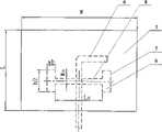
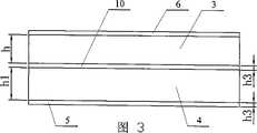
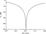
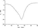
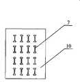
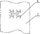
图1是本发明的圆柱共形4×4微带天线阵列的模型示意图,图2是天线单元主视展开图(省略了圆柱形载体2),图3是图2的俯视图,图4是天线单元的S11仿真图,图5是天线单元的二维辐射方向图,图6是圆柱共形4×4阵列的S11仿真图,图7是圆柱共形4×4二维辐射方向图,图8是贴片层5的主视图,图9是设置有H形槽7的中间地板10的主视图,图10是馈电网络层6的主视图。Fig. 1 is the schematic diagram of the model of cylindrical conformal 4 * 4 microstrip antenna array of the present invention, and Fig. 2 is the front view development view of antenna unit (
具体实施方式Detailed ways
具体实施方式一:结合图1~图3和图8~图10说明本实施方式,本实施方式的微带天线由十六个天线单元1和圆柱形载体2组成;所述十六个天线单元1分成四组,每组四个天线单元1呈矩形设置,四组天线单元1整体呈矩形设置在圆柱形载体2的表面上,所述天线单元1由第一介质层3、第二介质层4、中间地板10、贴片层5、馈电网络层6组成,所述馈电网络层6的内表面与圆柱形载体2的表面固接,馈电网络层6的外表面与第一介质层3的内表面固接,第一介质层3的外表面与中间地板10的内表面固接、中间地板10的外表面与第二介质层4的内表面固接,第二介质层4的外表面与贴片层5的内表面固接,中间地板10上设置有H形槽7,H形槽7的槽深与中间地板10的厚度一致,第一介质层3和第二介质层4的介质常数均为2.2,中间地板10的介质为理想导体(PEC)。采用耦合馈电的方式,能量通过中间地板10上的H形槽7耦合到贴片层5上。Specific Embodiment 1: This embodiment is described in conjunction with FIGS. 1 to 3 and FIGS. 8 to 10. The microstrip antenna of this embodiment is composed of sixteen
具体实施方式二:结合图1和图3说明本实施方式,本实施方式的第一介质层3的厚度h为0.25mm,所述第二介质层4的厚度h1为0.50mm,中间地板10和贴片层5的厚度h3均为0.018mm,H型槽7的横向槽8的长度Ls为1.3mm,H型槽7的横向槽8的宽度Ws为0.2mm;H型槽7的纵向槽9的长度h2为0.5mm,H型槽7的纵向槽8的宽度wh为0.25mm,天线单元1的长度×宽度=L×W=2mm×3.6mm。本实施方式确定的性能参数可使天线的谐振频率正好为35GHz,附图4中显示该天线的带宽超过10.9%(33.3~37.1GHz),附图5显示天线增益达6.54dB,辐射方向-E面和H面非常接近,说明馈线对方向图的影响比较小,这对于共形阵获得均匀的远场辐射方向图是有利的。Specific embodiment two: this embodiment is described in conjunction with Fig. 1 and Fig. 3, the thickness h of the first
具体实施方式三:本实施方式的微带天线的设计方法是这样完成的:利用H形槽7耦合馈电微带天线单元在CST中设计一个带有H形槽7的平面4×4微带天线阵列,画出不同半径、不同材料的圆柱体,然后利用“substrate”功能减出不同厚度的圆柱形载体2,分别将平面天线的馈电网络层6、第一介质层3、中间地板10、第二介质层4和贴片层5拉伸到圆柱形载体2上,利用“intersect”功能取出两者的交集即可将平面阵列共形到圆柱形载体2上。从仿真结果可以看出(见附图6和附图7),天线的谐振频率正好在35GHz,天线的带宽(VSWR=2)约为3.05GHz(接近10%),天线的增益达到了18.5dB,副瓣电平为-12.7dB(参见图1~图3和图8~图10)。Specific embodiment three: the design method of the microstrip antenna of the present embodiment is accomplished like this: Utilize the H-
Claims (6)
Translated fromChinesePriority Applications (1)
| Application Number | Priority Date | Filing Date | Title |
|---|---|---|---|
| CN200710144467ACN101281998B (en) | 2007-10-19 | 2007-10-19 | Millimeter wave band broadband cylinder conformal 4*4 microstrip antenna |
Applications Claiming Priority (1)
| Application Number | Priority Date | Filing Date | Title |
|---|---|---|---|
| CN200710144467ACN101281998B (en) | 2007-10-19 | 2007-10-19 | Millimeter wave band broadband cylinder conformal 4*4 microstrip antenna |
Publications (2)
| Publication Number | Publication Date |
|---|---|
| CN101281998Atrue CN101281998A (en) | 2008-10-08 |
| CN101281998B CN101281998B (en) | 2012-09-05 |
Family
ID=40014344
Family Applications (1)
| Application Number | Title | Priority Date | Filing Date |
|---|---|---|---|
| CN200710144467AExpired - Fee RelatedCN101281998B (en) | 2007-10-19 | 2007-10-19 | Millimeter wave band broadband cylinder conformal 4*4 microstrip antenna |
Country Status (1)
| Country | Link |
|---|---|
| CN (1) | CN101281998B (en) |
Cited By (21)
| Publication number | Priority date | Publication date | Assignee | Title |
|---|---|---|---|---|
| CN101388484B (en)* | 2008-10-09 | 2012-01-11 | 北京航空航天大学 | Thin-film omni-directional wideband surface conformal antenna |
| CN102427160A (en)* | 2011-08-10 | 2012-04-25 | 南京信息职业技术学院 | Conformal antenna for cylindrical carrier and application method thereof |
| CN102683809A (en)* | 2012-03-02 | 2012-09-19 | 四川大学 | Bandwidth miniaturization conformal monopole antenna |
| CN103337714A (en)* | 2013-06-06 | 2013-10-02 | 广州科技贸易职业学院 | Dielectric resonant antenna array based on electromagnetic band-gap material |
| CN104064851A (en)* | 2013-03-24 | 2014-09-24 | 成都携恩科技有限公司 | Patch antenna aperture-coupled feeding apparatus for RFID (Radio Frequency Identification Devices) |
| CN104953256A (en)* | 2015-05-25 | 2015-09-30 | 电子科技大学 | Broadband circularly-polarized panel array antenna |
| CN105305076A (en)* | 2015-11-30 | 2016-02-03 | 上海航天测控通信研究所 | Antenna structure integrated with monitoring network |
| CN106229686A (en)* | 2016-08-31 | 2016-12-14 | 上海捷士太通讯技术有限公司 | A kind of Broadband Circular Polarization Microstrip Antenna |
| CN106299631A (en)* | 2015-05-11 | 2017-01-04 | 南京理工大学 | A kind of double frequency Conformal Phased Array Missile-borne Antenna |
| WO2018058840A1 (en)* | 2016-09-30 | 2018-04-05 | 深圳市信维通信股份有限公司 | Dual-band array antenna for fifth generation wireless communications |
| CN109066087A (en)* | 2018-08-28 | 2018-12-21 | 昆山睿翔讯通通信技术有限公司 | A kind of four unit millimeter wave antenna system of communication terminal |
| CN109449583A (en)* | 2018-10-31 | 2019-03-08 | 安徽四创电子股份有限公司 | A kind of 5G Millimeter Wave Phased Array Antenna |
| CN110333488A (en)* | 2019-07-23 | 2019-10-15 | 上海雪狸传感技术有限公司 | A kind of wide angle beam scanning radar sensor of millimeter wave |
| CN110380201A (en)* | 2019-07-01 | 2019-10-25 | 中国航空工业集团公司雷华电子技术研究所 | A kind of X and ka two waveband is total to mouth face micro-strip array antenna |
| CN110611152A (en)* | 2019-10-11 | 2019-12-24 | 中国人民解放军第六九O五工厂 | Miniaturized Conformal Antennas |
| TWI682583B (en)* | 2017-11-30 | 2020-01-11 | 財團法人金屬工業研究發展中心 | Multi-antenna system using non-radiative coupling edges to achieve isolation |
| CN111505615A (en)* | 2020-04-27 | 2020-08-07 | 南京恩瑞特实业有限公司 | Transverse cylindrical surface dual-polarization phased array module and radar system |
| CN111624633A (en)* | 2020-04-29 | 2020-09-04 | 西南电子技术研究所(中国电子科技集团公司第十研究所) | Receiving and processing method of spin carrier navigation signal |
| CN112467355A (en)* | 2019-09-06 | 2021-03-09 | 启碁科技股份有限公司 | Antenna system |
| CN113206382A (en)* | 2021-04-27 | 2021-08-03 | 南通路远科技信息有限公司 | Feed antenna unit for automobile navigation |
| CN113300102A (en)* | 2020-10-12 | 2021-08-24 | 贵州航天林泉电机有限公司 | Conformal transmitting antenna structure for sounding rocket |
Family Cites Families (2)
| Publication number | Priority date | Publication date | Assignee | Title |
|---|---|---|---|---|
| US5844523A (en)* | 1996-02-29 | 1998-12-01 | Minnesota Mining And Manufacturing Company | Electrical and electromagnetic apparatuses using laminated structures having thermoplastic elastomeric and conductive layers |
| CN2914367Y (en)* | 2006-05-15 | 2007-06-20 | 中国电子科技集团公司第五十四研究所 | Omni conformal airborne aerial |
- 2007
- 2007-10-19CNCN200710144467Apatent/CN101281998B/ennot_activeExpired - Fee Related
Cited By (29)
| Publication number | Priority date | Publication date | Assignee | Title |
|---|---|---|---|---|
| CN101388484B (en)* | 2008-10-09 | 2012-01-11 | 北京航空航天大学 | Thin-film omni-directional wideband surface conformal antenna |
| CN102427160A (en)* | 2011-08-10 | 2012-04-25 | 南京信息职业技术学院 | Conformal antenna for cylindrical carrier and application method thereof |
| CN102427160B (en)* | 2011-08-10 | 2015-03-11 | 南京信息职业技术学院 | Conformal antenna for cylindrical carrier |
| CN102683809A (en)* | 2012-03-02 | 2012-09-19 | 四川大学 | Bandwidth miniaturization conformal monopole antenna |
| CN102683809B (en)* | 2012-03-02 | 2014-04-16 | 四川大学 | Bandwidth miniaturization conformal monopole antenna |
| CN104064851A (en)* | 2013-03-24 | 2014-09-24 | 成都携恩科技有限公司 | Patch antenna aperture-coupled feeding apparatus for RFID (Radio Frequency Identification Devices) |
| CN103337714A (en)* | 2013-06-06 | 2013-10-02 | 广州科技贸易职业学院 | Dielectric resonant antenna array based on electromagnetic band-gap material |
| CN106299631A (en)* | 2015-05-11 | 2017-01-04 | 南京理工大学 | A kind of double frequency Conformal Phased Array Missile-borne Antenna |
| CN104953256A (en)* | 2015-05-25 | 2015-09-30 | 电子科技大学 | Broadband circularly-polarized panel array antenna |
| CN104953256B (en)* | 2015-05-25 | 2018-01-12 | 电子科技大学 | Broadband circle polarized flat plate array antenna |
| CN105305076A (en)* | 2015-11-30 | 2016-02-03 | 上海航天测控通信研究所 | Antenna structure integrated with monitoring network |
| CN105305076B (en)* | 2015-11-30 | 2018-10-12 | 上海航天测控通信研究所 | The antenna structure of integrated monitor network |
| CN106229686A (en)* | 2016-08-31 | 2016-12-14 | 上海捷士太通讯技术有限公司 | A kind of Broadband Circular Polarization Microstrip Antenna |
| CN106229686B (en)* | 2016-08-31 | 2023-03-17 | 上海捷士太通讯技术有限公司 | Broadband circularly polarized microstrip antenna |
| WO2018058840A1 (en)* | 2016-09-30 | 2018-04-05 | 深圳市信维通信股份有限公司 | Dual-band array antenna for fifth generation wireless communications |
| TWI682583B (en)* | 2017-11-30 | 2020-01-11 | 財團法人金屬工業研究發展中心 | Multi-antenna system using non-radiative coupling edges to achieve isolation |
| CN109066087A (en)* | 2018-08-28 | 2018-12-21 | 昆山睿翔讯通通信技术有限公司 | A kind of four unit millimeter wave antenna system of communication terminal |
| CN109449583A (en)* | 2018-10-31 | 2019-03-08 | 安徽四创电子股份有限公司 | A kind of 5G Millimeter Wave Phased Array Antenna |
| CN110380201A (en)* | 2019-07-01 | 2019-10-25 | 中国航空工业集团公司雷华电子技术研究所 | A kind of X and ka two waveband is total to mouth face micro-strip array antenna |
| CN110333488A (en)* | 2019-07-23 | 2019-10-15 | 上海雪狸传感技术有限公司 | A kind of wide angle beam scanning radar sensor of millimeter wave |
| CN112467355A (en)* | 2019-09-06 | 2021-03-09 | 启碁科技股份有限公司 | Antenna system |
| CN112467355B (en)* | 2019-09-06 | 2023-07-18 | 启碁科技股份有限公司 | antenna system |
| CN110611152A (en)* | 2019-10-11 | 2019-12-24 | 中国人民解放军第六九O五工厂 | Miniaturized Conformal Antennas |
| CN111505615A (en)* | 2020-04-27 | 2020-08-07 | 南京恩瑞特实业有限公司 | Transverse cylindrical surface dual-polarization phased array module and radar system |
| CN111505615B (en)* | 2020-04-27 | 2022-06-21 | 南京恩瑞特实业有限公司 | Transverse cylindrical surface dual-polarization phased array module and radar system |
| CN111624633A (en)* | 2020-04-29 | 2020-09-04 | 西南电子技术研究所(中国电子科技集团公司第十研究所) | Receiving and processing method of spin carrier navigation signal |
| CN111624633B (en)* | 2020-04-29 | 2022-06-14 | 西南电子技术研究所(中国电子科技集团公司第十研究所) | Receiving and processing method of spin carrier navigation signal |
| CN113300102A (en)* | 2020-10-12 | 2021-08-24 | 贵州航天林泉电机有限公司 | Conformal transmitting antenna structure for sounding rocket |
| CN113206382A (en)* | 2021-04-27 | 2021-08-03 | 南通路远科技信息有限公司 | Feed antenna unit for automobile navigation |
Also Published As
| Publication number | Publication date |
|---|---|
| CN101281998B (en) | 2012-09-05 |
Similar Documents
| Publication | Publication Date | Title |
|---|---|---|
| CN101281998B (en) | Millimeter wave band broadband cylinder conformal 4*4 microstrip antenna | |
| CN112259961B (en) | Multi-octave ultra-wideband antenna and conformal array antenna | |
| CN101267063A (en) | A millimeter-wave band 4×4 conical conformal dual-band microstrip antenna and its design method | |
| Gao et al. | A dual-polarized 2-D monopulse antenna array for conical conformal applications | |
| CN108134193A (en) | A kind of compact-sized active-passive composite polarization sensitive array antenna assembly | |
| CN108173002A (en) | A Composite Polarization Sensitive Array Device Based on Conformal Vivaldi Antenna | |
| CN108879079A (en) | A kind of high-isolation array antenna based on electromagnetic wave absorption body | |
| CN215342974U (en) | Microstrip Antennas, Antenna Arrays and Weapon Systems | |
| CN212968050U (en) | Multi-octave ultra-wideband antenna and conformal array antenna | |
| CN113725585B (en) | Metal platform embedded vertical polarization ultra-wideband conformal end-fire antenna | |
| CN101202374A (en) | A Conical Conformal 4×4 Microstrip Antenna in the Millimeter Wave Band and Its Design Method | |
| Kavitha et al. | A wide-scan phased array antenna for a small active electronically scanned array: a review | |
| CN109659708A (en) | A kind of connected elongated slot antenna array of low RCS ultra wide band based on the load of resistive Meta Materials | |
| CN108242600B (en) | A Linearly Polarized Monopulse Flat Slot Antenna | |
| Nunna et al. | Design and analysis of single layer C/X-band conformal shared aperture antenna array for spaceborne SAR applications | |
| Chopra et al. | Design of an X-band conformal antenna using microstrip patches | |
| Nunna et al. | Design and analysis of X-band conformal antenna array for spaceborne synthetic aperture radar applications | |
| Wu et al. | A millimeter-wave conformal phased microstrip antenna array on a cylindrical surface | |
| CN104300228A (en) | Linear polarization microstrip patch antenna with L-band microstrip feed gap radiation | |
| Yerrola et al. | High gain beam steering antenna arrays with low scan loss for mmWave applications | |
| AU2021103887A4 (en) | Multi-octave ultra-wideband antenna and conformal array antenna | |
| Qiang et al. | A design of conformal dipole array for aircraft applications | |
| Bodur et al. | A novel reflecarray antenna backed with double layer FSS for RCS reduction | |
| CN103746188B (en) | Dual circularly polarized S-band printed antenna based on gap perturbation | |
| CN209822869U (en) | Coaxial transmission line directional antenna |
Legal Events
| Date | Code | Title | Description |
|---|---|---|---|
| C06 | Publication | ||
| PB01 | Publication | ||
| C10 | Entry into substantive examination | ||
| SE01 | Entry into force of request for substantive examination | ||
| C14 | Grant of patent or utility model | ||
| GR01 | Patent grant | ||
| C17 | Cessation of patent right | ||
| CF01 | Termination of patent right due to non-payment of annual fee | Granted publication date:20120905 Termination date:20121019 |