CN101281419A - Power Supply Module for Computer Devices - Google Patents
Power Supply Module for Computer DevicesDownload PDFInfo
- Publication number
- CN101281419A CN101281419ACNA2007100968243ACN200710096824ACN101281419ACN 101281419 ACN101281419 ACN 101281419ACN A2007100968243 ACNA2007100968243 ACN A2007100968243ACN 200710096824 ACN200710096824 ACN 200710096824ACN 101281419 ACN101281419 ACN 101281419A
- Authority
- CN
- China
- Prior art keywords
- power
- power supply
- transistor
- unit
- control signal
- Prior art date
- Legal status (The legal status is an assumption and is not a legal conclusion. Google has not performed a legal analysis and makes no representation as to the accuracy of the status listed.)
- Pending
Links
- 230000002035prolonged effectEffects0.000abstract1
- 238000010586diagramMethods0.000description4
- 239000003990capacitorSubstances0.000description2
- 238000000034methodMethods0.000description1
- 238000012986modificationMethods0.000description1
- 230000004048modificationEffects0.000description1
- 230000000087stabilizing effectEffects0.000description1
Images

Landscapes
- Power Sources (AREA)
Abstract
Description
Translated fromChinese技术领域technical field
本发明是有关于一种电脑装置的电源供应模块,且特别是有关于一种可增加电脑于关机时电池待机时间的电源供应模块。The present invention relates to a power supply module of a computer device, and in particular to a power supply module capable of increasing battery standby time when the computer is turned off.
背景技术Background technique
笔记本电脑轻巧且携带方便,使得使用率日渐普及。为了达到便于携带及使用之目的,电池电量的提供即显得非常重要。因此,使用者一般在不使用的情况下,将笔记本电脑的电源(Power)关闭以避免耗费电池电量。然而,即使在电源关闭的情形下,由于电路回路特性仍无法完全切断电池供电。因此,无法避免笔记型电脑于电源关闭后停止电源持续耗电的情况发生。Laptops are lightweight and portable, making their use increasingly common. In order to achieve the purpose of portability and use, the provision of battery power is very important. Therefore, users generally turn off the power supply (Power) of the notebook computer to avoid consuming battery power when not in use. However, even when the power is turned off, it is still impossible to completely cut off the battery power supply due to the characteristics of the circuit loop. Therefore, it is unavoidable that the notebook computer stops power consumption and continues to consume power after the power is turned off.
当电池放入笔记本电脑,系统电源会持续不断的耗电。此时若是交流变压器(AC Adapter)没有插入主机,一般笔记本电脑只要一到两个月不使用,电池电量即被内部集成电路(Integrated Circuit,IC)消耗完毕。所以使用上会造成麻烦,并且衰减电池的使用寿命。When the battery is put into the notebook computer, the system power will be continuously drained. If the AC adapter (AC Adapter) is not plugged into the host computer at this time, as long as the notebook computer is not used for one to two months, the battery power will be completely consumed by the internal integrated circuit (IC). Therefore, it will cause trouble in use and reduce the service life of the battery.
图1绘示为现有电脑装置的方块图。请参照图1,此电脑装置100包括电源开关101、电池110、键盘控制器120和电脑系统130,其中电池110还包括控制端111、正电源端112和负电源端113。由图1可看出,电池110的正电源端112和负电源端113与电脑系统130连接,并形成一回路。即使在电脑系统130的电源关闭时,电池110还是持续供电。虽然电量的消耗没有在电脑系统130开机时消耗的快,但是电池110的电量仍持续不断地在消耗,直到电量被消耗完毕。因此,电脑系统130的使用时间缩短并且减少电池110的待机时间,造成使用上的不便利。FIG. 1 is a block diagram of a conventional computer device. Referring to FIG. 1 , the
发明内容Contents of the invention
本发明的目的就是在提供一种电脑装置的电源供应模块,可减少不必要的电量损耗,进而增加电脑于关机时电池的待机时间,并延长电池的使用寿命。The purpose of the present invention is to provide a power supply module for a computer device, which can reduce unnecessary power consumption, further increase the battery standby time when the computer is turned off, and prolong the service life of the battery.
本发明提出一种适用于电脑系统的电源供应模块。此电源供应模块包括电源单元、切换单元和开关单元。电源单元具有控制端、第一电源端和第二电源端,其中此控制端接收控制信号,使得电源单元依据上述控制信号而决定是否从第一电源端和第二电源端供应工作电源给电脑系统。切换单元依据电脑系统是否启动而决定控制信号的状态。开关单元耦接切换单元,用以决定电脑系统是否启动。当电脑系统在关闭的状态而开关单元被使能时,则触发信号被产生并且传送给电脑系统,以控制切换单元将控制信号切换为第一状态,使得电源单元供应工作电源。当电脑系统被控制关机时,则控制该切换单元将控制信号切换为第二状态,以使电源单元停止供应工作电源。The invention proposes a power supply module suitable for a computer system. The power supply module includes a power supply unit, a switch unit and a switch unit. The power supply unit has a control terminal, a first power supply terminal and a second power supply terminal, wherein the control terminal receives a control signal, so that the power supply unit decides whether to supply working power to the computer system from the first power supply terminal and the second power supply terminal according to the above control signal . The switching unit determines the state of the control signal according to whether the computer system is activated. The switch unit is coupled to the switch unit for determining whether the computer system is started. When the computer system is turned off and the switch unit is enabled, a trigger signal is generated and sent to the computer system to control the switch unit to switch the control signal to the first state, so that the power supply unit supplies working power. When the computer system is controlled to shut down, the switching unit is controlled to switch the control signal to the second state, so that the power supply unit stops supplying working power.
从另一观点来看,本发明再提出一种电脑装置,此电脑装置包括主系统、基本控制单元、电源单元、开关单元和电源控制单元。基本控制单元耦接至主系统。电源单元具有控制端、第一电源端和第二电源端,其中控制端接收控制信号,使得电源单元依据上述控制信号而决定是否从第一电源端和第二电源端供应工作电源给主系统。电源控制单元耦接基本控制单元,以依据基本控制单元的输出而决定控制信号的状态。开关单元耦接电源控制单元,用以决定是否启动主系统。当主系统在关闭的状态而开关单元被使能时,则基本控制单元接收到触发信号,导致基本控制单元控制电源控制单元将控制信号切换为第一状态,以使电源单元供应工作电源。当主系统被控制关机时,则基本控制单元控制电源控制单元将控制信号切换为第二状态,以使电源单元停止供应工作电源。From another point of view, the present invention further proposes a computer device, which includes a main system, a basic control unit, a power supply unit, a switch unit, and a power supply control unit. The basic control unit is coupled to the main system. The power supply unit has a control terminal, a first power supply terminal and a second power supply terminal, wherein the control terminal receives a control signal, so that the power supply unit decides whether to supply operating power to the main system from the first power supply terminal and the second power supply terminal according to the control signal. The power control unit is coupled to the basic control unit to determine the state of the control signal according to the output of the basic control unit. The switch unit is coupled to the power control unit for determining whether to start the main system. When the main system is in the off state and the switch unit is enabled, the basic control unit receives the trigger signal, causing the basic control unit to control the power control unit to switch the control signal to the first state, so that the power supply unit supplies working power. When the main system is shut down, the basic control unit controls the power control unit to switch the control signal to the second state, so that the power supply unit stops supplying working power.
本发明通过控制切换单元的控制信号的状态,而电源单元再根据此控制信号的状态决定是否提供工作电源。因此,可有效阻绝电池电量持续消耗,进而达到增加电池的待机时间以及延长电池的使用寿命。The present invention controls the state of the control signal of the switching unit, and the power supply unit decides whether to provide working power according to the state of the control signal. Therefore, the continuous consumption of battery power can be effectively prevented, thereby increasing the standby time of the battery and prolonging the service life of the battery.
为让本发明的上述和其他目的、特征和优点能更明显易懂,下文特举较佳实施例,并配合附图作详细说明如下。In order to make the above and other objects, features and advantages of the present invention more comprehensible, preferred embodiments are exemplified below and described in detail with accompanying drawings.
附图说明Description of drawings
图1绘示为现有的电脑装置的方块图。FIG. 1 is a block diagram of a conventional computer device.
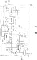
图2绘示为依照本发明的一较佳实施例的电脑装置的电路图。FIG. 2 is a circuit diagram of a computer device according to a preferred embodiment of the present invention.
具体实施方式Detailed ways
图2绘示为依照本发明一较佳实施例的电脑装置的电路图。请参照图2,本发明所提供的电脑装置200包括一电源供应模块210和一电脑系统260。其中,电源供应模块210耦接至电脑系统260,以供应其运行所需的电力。而电脑系统260可为一可携式电脑系统。FIG. 2 is a circuit diagram of a computer device according to a preferred embodiment of the present invention. Please refer to FIG. 2 , the
在本实施例中,电脑单元260包括主系统261和基本控制单元262。其中,基本控制单元262例如是可携式电脑的键盘控制器,并且耦接至主系统261,以决定主系统261是否启动。In this embodiment, the computer unit 260 includes a
另外,电源供应模块210包括电源单元220、开关单元230和电源控制单元270。其中,电源单元220具有控制端221、第一电源端222(例如为正电源端)和第二电源端223(例如为负电源端),以提供电脑装置200内部电路所需的工作电源。此电源单元220的控制端221接收一控制信号CS,并且依据此控制信号CS的状态而决定是否从第一和第二电源端222、223供应工作电源给电脑系统260。In addition, the
在本实施例中,开关单元230可为电脑的电源开关,其一端耦接至电源控制单元270,而其另一端耦接至接地端GND。In this embodiment, the
此外,电源控制单元270耦接至开关单元230和电源单元220和电脑系统260的基本控制单元262。藉此,电源控制单元270可以依据基本控制单元262的输出以及开关单元230是否被使能,而决定控制信号CS的状态,进而控制电源单元220是否供应工作电源。In addition, the
请继续参照图2,电源控制单元270包括切换单元240、电容C直流对直流转换器250和电阻R。切换单元240耦接至基本控制单元262,并且依据主系统261是否启动而决定控制信号CS的状态。Please continue to refer to FIG. 2 , the
在本实施例中,电源控制单元270中的电容C可以作为稳压元件,而直流对直流转换器250则是将电源单元220的第一电源端222耦接至基本控制单元262,并通过电阻R耦接至开关单元230和切换单元240。切换单元240包括二极管D、第一晶体管Tr1、第一电阻R1和第二电阻R2。其中,二极管D可为一肖特基二极管(Schottky Diode),其阴极端耦接至开关单元230,而其阳极端耦接至电源单元220,以限制电流流动的方向(也即避免直流对直流转换器250输出的电流回流至电源单元220)。第一晶体管Tr1可为一NPN双极性晶体管,其集极端耦接至二极管D的阳极端和电源单元220的控制端221,而其射极端则耦接至接地端GND,用以决定控制信号CS的状态。In this embodiment, the capacitor C in the
此外,第一电阻R1耦接于第一晶体管Tr1的基极端和基本控制单元262之间。第二电阻R2耦接于第一晶体管Tr1的基极端和其射极端之间。此两电阻R1、R2作为限流元件,以防止流至第一晶体管Tr1的电流过大,而使得第一晶体管Tr1损毁。In addition, the first resistor R1 is coupled between the base terminal of the first transistor Tr1 and the
在本实施例中,电源单元220包括电池模块225、第二晶体管Tr2、第三晶体管Tr3和微控制器226。其中,第二和第三晶体管Tr2、Tr3为NMOS晶体管。电池模块225分别耦接至微控制器226、电源单元220的第二电源端223和第二晶体管Tr2的第一源/漏极端,以供应电脑装置200所需的工作电源。第三晶体管Tr3的第一源/漏极端耦接至第二晶体管Tr2的第二源/漏极端,而其第二源/漏极端则耦接至第一电源端222。In this embodiment, the
而微控制器226分别耦接至控制端221、第二晶体管Tr2和第三晶体管Tr3的栅极端,并依据控制信号CS的状态而决定第二和第三晶体管Tr2、Tr3是否导通。在主系统261关闭的情形下,控制信号CS为浮接(floating)状态,因此电池模块225不提供工作电源给电脑系统260。而当开关单元230被使能时,此时二极管D导通,使得控制信号CS转换为一接地电位。The
接着,当微控制器226接收此控制信号CS,则控制第二和第三晶体管Tr2、Tr3导通。由于第二和第三晶体管Tr2、Tr3导通,此时电池模块225输出一电压至直流对直流转换器250而产生一触发信号,并传送至基本控制单元262。Next, when the
当基本控制单元262接收此触发信号后,会输出一开机信号(高电压电平)经由第一电阻R1传送至第一晶体管Tr1,使得第一晶体管Tr1导通。此时,开关单元230为失能状态,所以控制信号CS为浮接状态。由于第一晶体管Tr1导通,则切换单元240将控制信号CS再转换为接地电位,并且传送至微控制器226,使得第二和第三晶体管Tr2、Tr3再次导通。因此,电池模块225可供电给电脑系统260,并使主系统261可正常运行。在电池模块225供电的同时,基本控制单元262的电源则由电池模块225提供,以使得第一晶体管Tr1可持续导通,让电池模块225可继续提供工作电源。When the
另外,当主系统261例如被使用者通过作业系统控制关闭时,基本控制单元262会输出一关机信号(低电压电平)经由第一电阻R1传送至第一晶体管Tr1,使得第一晶体管Tr1截止。由于第一晶体管Tr1截止,在切换单元240中控制信号CS状态将转换为浮接状态,并传送至微控制器226。当微控制器226接收此控制信号CS后,则控制第二和第三晶体管Tr2、Tr3截止,使得电池模块225不再提供工作电源。因此,在主系统261关闭后,电池模块225不再提供工作电压,可减少不必要的电量消耗,进而可增加电池模块225的待机时间。In addition, when the
综上所述,由于本发明所提供的电源供应模块,可控制电池模块是否供电。当电脑系统开始运行时,则提供工作电源给电脑系统使用,而当电脑系统关机时,则完全切断电源的供应,并且使电池模块的电量不在继续消耗。因此,以本发明所提供的电源供应模块可有效地解决电池电量持续损耗的问题并增加电池使用的时间。To sum up, due to the power supply module provided by the present invention, it is possible to control whether the battery module supplies power. When the computer system starts to run, it provides working power for the computer system, and when the computer system is shut down, it completely cuts off the power supply, and keeps the power of the battery module from being consumed. Therefore, the power supply module provided by the present invention can effectively solve the problem of continuous power loss of the battery and increase the service time of the battery.
虽然本发明已以较佳实施例揭示如上,然其并非用以限定本发明,任何熟习此技艺者,在不脱离本发明的精神和范围内,当可作些许更动与润饰,因此本发明的保护范围当以权利要求所界定的为准。Although the present invention has been disclosed above with preferred embodiments, it is not intended to limit the present invention. Anyone skilled in the art can make some changes and modifications without departing from the spirit and scope of the present invention. Therefore, the present invention The scope of protection should be defined by the claims.
Claims (18)
Priority Applications (1)
| Application Number | Priority Date | Filing Date | Title |
|---|---|---|---|
| CNA2007100968243ACN101281419A (en) | 2007-04-04 | 2007-04-04 | Power Supply Module for Computer Devices |
Applications Claiming Priority (1)
| Application Number | Priority Date | Filing Date | Title |
|---|---|---|---|
| CNA2007100968243ACN101281419A (en) | 2007-04-04 | 2007-04-04 | Power Supply Module for Computer Devices |
Publications (1)
| Publication Number | Publication Date |
|---|---|
| CN101281419Atrue CN101281419A (en) | 2008-10-08 |
Family
ID=40013913
Family Applications (1)
| Application Number | Title | Priority Date | Filing Date |
|---|---|---|---|
| CNA2007100968243APendingCN101281419A (en) | 2007-04-04 | 2007-04-04 | Power Supply Module for Computer Devices |
Country Status (1)
| Country | Link |
|---|---|
| CN (1) | CN101281419A (en) |
Cited By (4)
| Publication number | Priority date | Publication date | Assignee | Title |
|---|---|---|---|---|
| CN101887299B (en)* | 2009-05-15 | 2012-09-19 | 华硕电脑股份有限公司 | Power supply control circuit and control method for computer system |
| CN102759887A (en)* | 2011-04-28 | 2012-10-31 | 群康科技(深圳)有限公司 | Electronic device, personal computer, host and display |
| CN103135736A (en)* | 2011-11-25 | 2013-06-05 | 英业达股份有限公司 | Power backup system |
| CN109417206A (en)* | 2018-09-03 | 2019-03-01 | 深圳迈瑞生物医疗电子股份有限公司 | A power management circuit |
- 2007
- 2007-04-04CNCNA2007100968243Apatent/CN101281419A/enactivePending
Cited By (6)
| Publication number | Priority date | Publication date | Assignee | Title |
|---|---|---|---|---|
| CN101887299B (en)* | 2009-05-15 | 2012-09-19 | 华硕电脑股份有限公司 | Power supply control circuit and control method for computer system |
| CN102759887A (en)* | 2011-04-28 | 2012-10-31 | 群康科技(深圳)有限公司 | Electronic device, personal computer, host and display |
| CN102759887B (en)* | 2011-04-28 | 2015-03-11 | 群康科技(深圳)有限公司 | Electronic device, personal computer, host and display |
| CN103135736A (en)* | 2011-11-25 | 2013-06-05 | 英业达股份有限公司 | Power backup system |
| CN109417206A (en)* | 2018-09-03 | 2019-03-01 | 深圳迈瑞生物医疗电子股份有限公司 | A power management circuit |
| WO2020047693A1 (en)* | 2018-09-03 | 2020-03-12 | 深圳迈瑞生物医疗电子股份有限公司 | Power supply management circuit |
Similar Documents
| Publication | Publication Date | Title |
|---|---|---|
| CN101141078B (en) | Power supply equipment and electronic equipment | |
| US7805623B2 (en) | Power-save circuit for computer | |
| CN108736563B (en) | Electronic device and power supply method therefor | |
| CN101465600A (en) | Electronic equipment and power supply device thereof | |
| CN101281419A (en) | Power Supply Module for Computer Devices | |
| TWI461897B (en) | Power control device and electronic device using the same | |
| US9705323B2 (en) | Power supply system and power control circuit thereof | |
| CN101625588B (en) | Supply circuit of PWM controller | |
| CN112600283B (en) | Startup and shutdown circuit | |
| CN111756091B (en) | Power switching circuit and smart door lock | |
| CN212785304U (en) | Startup and shutdown circuit and POS machine | |
| CN113206522A (en) | Low standby power consumption power supply circuit and electronic equipment | |
| CN111399617A (en) | Power supply control device and electronic apparatus | |
| CN214590675U (en) | Power supply control circuit and electronic equipment | |
| CN102799249B (en) | A kind of computing machine and power control thereof | |
| CN217769863U (en) | Starting control circuit and electronic equipment | |
| CN219918421U (en) | Electronic equipment | |
| CN110943527B (en) | power supply device | |
| CN219268834U (en) | Automatic shutdown control circuit | |
| CN221574864U (en) | Overvoltage protection circuit and power supply | |
| CN216387790U (en) | Switching on and shutting down circuit and electrical equipment | |
| CN218724392U (en) | Low-power-consumption multifunctional radar flowmeter | |
| CN217824413U (en) | Uninterrupted power supply switching control circuit and device | |
| CN222301795U (en) | Switch circuits, circuit boards and electronic equipment | |
| CN220857661U (en) | Charging control circuit and device |
Legal Events
| Date | Code | Title | Description |
|---|---|---|---|
| C06 | Publication | ||
| PB01 | Publication | ||
| C10 | Entry into substantive examination | ||
| SE01 | Entry into force of request for substantive examination | ||
| C02 | Deemed withdrawal of patent application after publication (patent law 2001) | ||
| WD01 | Invention patent application deemed withdrawn after publication | Open date:20081008 |