CN101278127B - Expandable impeller pump - Google Patents
Expandable impeller pumpDownload PDFInfo
- Publication number
- CN101278127B CN101278127BCN2005800312271ACN200580031227ACN101278127BCN 101278127 BCN101278127 BCN 101278127BCN 2005800312271 ACN2005800312271 ACN 2005800312271ACN 200580031227 ACN200580031227 ACN 200580031227ACN 101278127 BCN101278127 BCN 101278127B
- Authority
- CN
- China
- Prior art keywords
- blade
- impeller
- wheel hub
- equipment
- deployment configuration
- Prior art date
- Legal status (The legal status is an assumption and is not a legal conclusion. Google has not performed a legal analysis and makes no representation as to the accuracy of the status listed.)
- Expired - Lifetime
Links
Images


Classifications
- F—MECHANICAL ENGINEERING; LIGHTING; HEATING; WEAPONS; BLASTING
- F04—POSITIVE - DISPLACEMENT MACHINES FOR LIQUIDS; PUMPS FOR LIQUIDS OR ELASTIC FLUIDS
- F04D—NON-POSITIVE-DISPLACEMENT PUMPS
- F04D29/00—Details, component parts, or accessories
- F04D29/18—Rotors
- F04D29/181—Axial flow rotors
- A—HUMAN NECESSITIES
- A61—MEDICAL OR VETERINARY SCIENCE; HYGIENE
- A61M—DEVICES FOR INTRODUCING MEDIA INTO, OR ONTO, THE BODY; DEVICES FOR TRANSDUCING BODY MEDIA OR FOR TAKING MEDIA FROM THE BODY; DEVICES FOR PRODUCING OR ENDING SLEEP OR STUPOR
- A61M60/00—Blood pumps; Devices for mechanical circulatory actuation; Balloon pumps for circulatory assistance
- A61M60/20—Type thereof
- A61M60/205—Non-positive displacement blood pumps
- A61M60/216—Non-positive displacement blood pumps including a rotating member acting on the blood, e.g. impeller
- A61M60/237—Non-positive displacement blood pumps including a rotating member acting on the blood, e.g. impeller the blood flow through the rotating member having mainly axial components, e.g. axial flow pumps
- A—HUMAN NECESSITIES
- A61—MEDICAL OR VETERINARY SCIENCE; HYGIENE
- A61M—DEVICES FOR INTRODUCING MEDIA INTO, OR ONTO, THE BODY; DEVICES FOR TRANSDUCING BODY MEDIA OR FOR TAKING MEDIA FROM THE BODY; DEVICES FOR PRODUCING OR ENDING SLEEP OR STUPOR
- A61M60/00—Blood pumps; Devices for mechanical circulatory actuation; Balloon pumps for circulatory assistance
- A61M60/40—Details relating to driving
- A61M60/403—Details relating to driving for non-positive displacement blood pumps
- A61M60/408—Details relating to driving for non-positive displacement blood pumps the force acting on the blood contacting member being mechanical, e.g. transmitted by a shaft or cable
- A61M60/411—Details relating to driving for non-positive displacement blood pumps the force acting on the blood contacting member being mechanical, e.g. transmitted by a shaft or cable generated by an electromotor
- A61M60/414—Details relating to driving for non-positive displacement blood pumps the force acting on the blood contacting member being mechanical, e.g. transmitted by a shaft or cable generated by an electromotor transmitted by a rotating cable, e.g. for blood pumps mounted on a catheter
- A—HUMAN NECESSITIES
- A61—MEDICAL OR VETERINARY SCIENCE; HYGIENE
- A61M—DEVICES FOR INTRODUCING MEDIA INTO, OR ONTO, THE BODY; DEVICES FOR TRANSDUCING BODY MEDIA OR FOR TAKING MEDIA FROM THE BODY; DEVICES FOR PRODUCING OR ENDING SLEEP OR STUPOR
- A61M60/00—Blood pumps; Devices for mechanical circulatory actuation; Balloon pumps for circulatory assistance
- A61M60/80—Constructional details other than related to driving
- A61M60/802—Constructional details other than related to driving of non-positive displacement blood pumps
- A61M60/804—Impellers
- A61M60/806—Vanes or blades
- A61M60/808—Vanes or blades specially adapted for deformable impellers, e.g. expandable impellers
- F—MECHANICAL ENGINEERING; LIGHTING; HEATING; WEAPONS; BLASTING
- F04—POSITIVE - DISPLACEMENT MACHINES FOR LIQUIDS; PUMPS FOR LIQUIDS OR ELASTIC FLUIDS
- F04D—NON-POSITIVE-DISPLACEMENT PUMPS
- F04D19/00—Axial-flow pumps
- F04D19/02—Multi-stage pumps
- F—MECHANICAL ENGINEERING; LIGHTING; HEATING; WEAPONS; BLASTING
- F04—POSITIVE - DISPLACEMENT MACHINES FOR LIQUIDS; PUMPS FOR LIQUIDS OR ELASTIC FLUIDS
- F04D—NON-POSITIVE-DISPLACEMENT PUMPS
- F04D29/00—Details, component parts, or accessories
- F04D29/02—Selection of particular materials
- F04D29/026—Selection of particular materials especially adapted for liquid pumps
- F—MECHANICAL ENGINEERING; LIGHTING; HEATING; WEAPONS; BLASTING
- F04—POSITIVE - DISPLACEMENT MACHINES FOR LIQUIDS; PUMPS FOR LIQUIDS OR ELASTIC FLUIDS
- F04D—NON-POSITIVE-DISPLACEMENT PUMPS
- F04D29/00—Details, component parts, or accessories
- F04D29/18—Rotors
- F04D29/22—Rotors specially for centrifugal pumps
- F04D29/24—Vanes
- F04D29/247—Vanes elastic or self-adjusting
- F—MECHANICAL ENGINEERING; LIGHTING; HEATING; WEAPONS; BLASTING
- F04—POSITIVE - DISPLACEMENT MACHINES FOR LIQUIDS; PUMPS FOR LIQUIDS OR ELASTIC FLUIDS
- F04D—NON-POSITIVE-DISPLACEMENT PUMPS
- F04D29/00—Details, component parts, or accessories
- F04D29/26—Rotors specially for elastic fluids
- F04D29/32—Rotors specially for elastic fluids for axial flow pumps
- F04D29/38—Blades
- F04D29/382—Flexible blades
- F—MECHANICAL ENGINEERING; LIGHTING; HEATING; WEAPONS; BLASTING
- F04—POSITIVE - DISPLACEMENT MACHINES FOR LIQUIDS; PUMPS FOR LIQUIDS OR ELASTIC FLUIDS
- F04D—NON-POSITIVE-DISPLACEMENT PUMPS
- F04D29/00—Details, component parts, or accessories
- F04D29/40—Casings; Connections of working fluid
- F04D29/52—Casings; Connections of working fluid for axial pumps
- F04D29/522—Casings; Connections of working fluid for axial pumps especially adapted for elastic fluid pumps
- F04D29/526—Details of the casing section radially opposing blade tips
- F—MECHANICAL ENGINEERING; LIGHTING; HEATING; WEAPONS; BLASTING
- F04—POSITIVE - DISPLACEMENT MACHINES FOR LIQUIDS; PUMPS FOR LIQUIDS OR ELASTIC FLUIDS
- F04D—NON-POSITIVE-DISPLACEMENT PUMPS
- F04D29/00—Details, component parts, or accessories
- F04D29/40—Casings; Connections of working fluid
- F04D29/52—Casings; Connections of working fluid for axial pumps
- F04D29/528—Casings; Connections of working fluid for axial pumps especially adapted for liquid pumps
- F—MECHANICAL ENGINEERING; LIGHTING; HEATING; WEAPONS; BLASTING
- F04—POSITIVE - DISPLACEMENT MACHINES FOR LIQUIDS; PUMPS FOR LIQUIDS OR ELASTIC FLUIDS
- F04D—NON-POSITIVE-DISPLACEMENT PUMPS
- F04D3/00—Axial-flow pumps
- F—MECHANICAL ENGINEERING; LIGHTING; HEATING; WEAPONS; BLASTING
- F04—POSITIVE - DISPLACEMENT MACHINES FOR LIQUIDS; PUMPS FOR LIQUIDS OR ELASTIC FLUIDS
- F04D—NON-POSITIVE-DISPLACEMENT PUMPS
- F04D3/00—Axial-flow pumps
- F04D3/02—Axial-flow pumps of screw type
- A—HUMAN NECESSITIES
- A61—MEDICAL OR VETERINARY SCIENCE; HYGIENE
- A61M—DEVICES FOR INTRODUCING MEDIA INTO, OR ONTO, THE BODY; DEVICES FOR TRANSDUCING BODY MEDIA OR FOR TAKING MEDIA FROM THE BODY; DEVICES FOR PRODUCING OR ENDING SLEEP OR STUPOR
- A61M60/00—Blood pumps; Devices for mechanical circulatory actuation; Balloon pumps for circulatory assistance
- A61M60/10—Location thereof with respect to the patient's body
- A61M60/122—Implantable pumps or pumping devices, i.e. the blood being pumped inside the patient's body
- A61M60/126—Implantable pumps or pumping devices, i.e. the blood being pumped inside the patient's body implantable via, into, inside, in line, branching on, or around a blood vessel
- A61M60/135—Implantable pumps or pumping devices, i.e. the blood being pumped inside the patient's body implantable via, into, inside, in line, branching on, or around a blood vessel inside a blood vessel, e.g. using grafting
- A—HUMAN NECESSITIES
- A61—MEDICAL OR VETERINARY SCIENCE; HYGIENE
- A61M—DEVICES FOR INTRODUCING MEDIA INTO, OR ONTO, THE BODY; DEVICES FOR TRANSDUCING BODY MEDIA OR FOR TAKING MEDIA FROM THE BODY; DEVICES FOR PRODUCING OR ENDING SLEEP OR STUPOR
- A61M60/00—Blood pumps; Devices for mechanical circulatory actuation; Balloon pumps for circulatory assistance
- A61M60/10—Location thereof with respect to the patient's body
- A61M60/122—Implantable pumps or pumping devices, i.e. the blood being pumped inside the patient's body
- A61M60/126—Implantable pumps or pumping devices, i.e. the blood being pumped inside the patient's body implantable via, into, inside, in line, branching on, or around a blood vessel
- A61M60/148—Implantable pumps or pumping devices, i.e. the blood being pumped inside the patient's body implantable via, into, inside, in line, branching on, or around a blood vessel in line with a blood vessel using resection or like techniques, e.g. permanent endovascular heart assist devices
- B—PERFORMING OPERATIONS; TRANSPORTING
- B63—SHIPS OR OTHER WATERBORNE VESSELS; RELATED EQUIPMENT
- B63B—SHIPS OR OTHER WATERBORNE VESSELS; EQUIPMENT FOR SHIPPING
- B63B2231/00—Material used for some parts or elements, or for particular purposes
- B63B2231/40—Synthetic materials
- B63B2231/42—Elastomeric materials
- B—PERFORMING OPERATIONS; TRANSPORTING
- B63—SHIPS OR OTHER WATERBORNE VESSELS; RELATED EQUIPMENT
- B63H—MARINE PROPULSION OR STEERING
- B63H1/00—Propulsive elements directly acting on water
- B63H1/02—Propulsive elements directly acting on water of rotary type
- B63H1/12—Propulsive elements directly acting on water of rotary type with rotation axis substantially in propulsive direction
- B63H1/14—Propellers
- B63H1/26—Blades
- B—PERFORMING OPERATIONS; TRANSPORTING
- B63—SHIPS OR OTHER WATERBORNE VESSELS; RELATED EQUIPMENT
- B63H—MARINE PROPULSION OR STEERING
- B63H11/00—Marine propulsion by water jets
- B63H11/02—Marine propulsion by water jets the propulsive medium being ambient water
- B63H11/04—Marine propulsion by water jets the propulsive medium being ambient water by means of pumps
- B63H11/08—Marine propulsion by water jets the propulsive medium being ambient water by means of pumps of rotary type
- F—MECHANICAL ENGINEERING; LIGHTING; HEATING; WEAPONS; BLASTING
- F03—MACHINES OR ENGINES FOR LIQUIDS; WIND, SPRING, OR WEIGHT MOTORS; PRODUCING MECHANICAL POWER OR A REACTIVE PROPULSIVE THRUST, NOT OTHERWISE PROVIDED FOR
- F03G—SPRING, WEIGHT, INERTIA OR LIKE MOTORS; MECHANICAL-POWER PRODUCING DEVICES OR MECHANISMS, NOT OTHERWISE PROVIDED FOR OR USING ENERGY SOURCES NOT OTHERWISE PROVIDED FOR
- F03G7/00—Mechanical-power-producing mechanisms, not otherwise provided for or using energy sources not otherwise provided for
- F03G7/06—Mechanical-power-producing mechanisms, not otherwise provided for or using energy sources not otherwise provided for using expansion or contraction of bodies due to heating, cooling, moistening, drying or the like
- F03G7/061—Mechanical-power-producing mechanisms, not otherwise provided for or using energy sources not otherwise provided for using expansion or contraction of bodies due to heating, cooling, moistening, drying or the like characterised by the actuating element
- F03G7/0614—Mechanical-power-producing mechanisms, not otherwise provided for or using energy sources not otherwise provided for using expansion or contraction of bodies due to heating, cooling, moistening, drying or the like characterised by the actuating element using shape memory elements
- F—MECHANICAL ENGINEERING; LIGHTING; HEATING; WEAPONS; BLASTING
- F05—INDEXING SCHEMES RELATING TO ENGINES OR PUMPS IN VARIOUS SUBCLASSES OF CLASSES F01-F04
- F05D—INDEXING SCHEME FOR ASPECTS RELATING TO NON-POSITIVE-DISPLACEMENT MACHINES OR ENGINES, GAS-TURBINES OR JET-PROPULSION PLANTS
- F05D2210/00—Working fluids
- F05D2210/10—Kind or type
- F05D2210/11—Kind or type liquid, i.e. incompressible
- F—MECHANICAL ENGINEERING; LIGHTING; HEATING; WEAPONS; BLASTING
- F05—INDEXING SCHEMES RELATING TO ENGINES OR PUMPS IN VARIOUS SUBCLASSES OF CLASSES F01-F04
- F05D—INDEXING SCHEME FOR ASPECTS RELATING TO NON-POSITIVE-DISPLACEMENT MACHINES OR ENGINES, GAS-TURBINES OR JET-PROPULSION PLANTS
- F05D2240/00—Components
- F05D2240/20—Rotors
- F05D2240/30—Characteristics of rotor blades, i.e. of any element transforming dynamic fluid energy to or from rotational energy and being attached to a rotor
- F05D2240/305—Characteristics of rotor blades, i.e. of any element transforming dynamic fluid energy to or from rotational energy and being attached to a rotor related to the pressure side of a rotor blade
- F—MECHANICAL ENGINEERING; LIGHTING; HEATING; WEAPONS; BLASTING
- F05—INDEXING SCHEMES RELATING TO ENGINES OR PUMPS IN VARIOUS SUBCLASSES OF CLASSES F01-F04
- F05D—INDEXING SCHEME FOR ASPECTS RELATING TO NON-POSITIVE-DISPLACEMENT MACHINES OR ENGINES, GAS-TURBINES OR JET-PROPULSION PLANTS
- F05D2240/00—Components
- F05D2240/20—Rotors
- F05D2240/30—Characteristics of rotor blades, i.e. of any element transforming dynamic fluid energy to or from rotational energy and being attached to a rotor
- F05D2240/306—Characteristics of rotor blades, i.e. of any element transforming dynamic fluid energy to or from rotational energy and being attached to a rotor related to the suction side of a rotor blade
- F—MECHANICAL ENGINEERING; LIGHTING; HEATING; WEAPONS; BLASTING
- F05—INDEXING SCHEMES RELATING TO ENGINES OR PUMPS IN VARIOUS SUBCLASSES OF CLASSES F01-F04
- F05D—INDEXING SCHEME FOR ASPECTS RELATING TO NON-POSITIVE-DISPLACEMENT MACHINES OR ENGINES, GAS-TURBINES OR JET-PROPULSION PLANTS
- F05D2250/00—Geometry
- F05D2250/50—Inlet or outlet
- F05D2250/51—Inlet
- F—MECHANICAL ENGINEERING; LIGHTING; HEATING; WEAPONS; BLASTING
- F05—INDEXING SCHEMES RELATING TO ENGINES OR PUMPS IN VARIOUS SUBCLASSES OF CLASSES F01-F04
- F05D—INDEXING SCHEME FOR ASPECTS RELATING TO NON-POSITIVE-DISPLACEMENT MACHINES OR ENGINES, GAS-TURBINES OR JET-PROPULSION PLANTS
- F05D2250/00—Geometry
- F05D2250/50—Inlet or outlet
- F05D2250/52—Outlet
- F—MECHANICAL ENGINEERING; LIGHTING; HEATING; WEAPONS; BLASTING
- F05—INDEXING SCHEMES RELATING TO ENGINES OR PUMPS IN VARIOUS SUBCLASSES OF CLASSES F01-F04
- F05D—INDEXING SCHEME FOR ASPECTS RELATING TO NON-POSITIVE-DISPLACEMENT MACHINES OR ENGINES, GAS-TURBINES OR JET-PROPULSION PLANTS
- F05D2300/00—Materials; Properties thereof
- F05D2300/40—Organic materials
- F05D2300/43—Synthetic polymers, e.g. plastics; Rubber
- Y—GENERAL TAGGING OF NEW TECHNOLOGICAL DEVELOPMENTS; GENERAL TAGGING OF CROSS-SECTIONAL TECHNOLOGIES SPANNING OVER SEVERAL SECTIONS OF THE IPC; TECHNICAL SUBJECTS COVERED BY FORMER USPC CROSS-REFERENCE ART COLLECTIONS [XRACs] AND DIGESTS
- Y10—TECHNICAL SUBJECTS COVERED BY FORMER USPC
- Y10S—TECHNICAL SUBJECTS COVERED BY FORMER USPC CROSS-REFERENCE ART COLLECTIONS [XRACs] AND DIGESTS
- Y10S415/00—Rotary kinetic fluid motors or pumps
- Y10S415/90—Rotary blood pump
- Y—GENERAL TAGGING OF NEW TECHNOLOGICAL DEVELOPMENTS; GENERAL TAGGING OF CROSS-SECTIONAL TECHNOLOGIES SPANNING OVER SEVERAL SECTIONS OF THE IPC; TECHNICAL SUBJECTS COVERED BY FORMER USPC CROSS-REFERENCE ART COLLECTIONS [XRACs] AND DIGESTS
- Y10—TECHNICAL SUBJECTS COVERED BY FORMER USPC
- Y10T—TECHNICAL SUBJECTS COVERED BY FORMER US CLASSIFICATION
- Y10T29/00—Metal working
- Y10T29/49—Method of mechanical manufacture
- Y10T29/49229—Prime mover or fluid pump making
Landscapes
- Engineering & Computer Science (AREA)
- Mechanical Engineering (AREA)
- Health & Medical Sciences (AREA)
- General Engineering & Computer Science (AREA)
- Heart & Thoracic Surgery (AREA)
- Biomedical Technology (AREA)
- Anesthesiology (AREA)
- Hematology (AREA)
- Life Sciences & Earth Sciences (AREA)
- Animal Behavior & Ethology (AREA)
- General Health & Medical Sciences (AREA)
- Public Health (AREA)
- Veterinary Medicine (AREA)
- Cardiology (AREA)
- Structures Of Non-Positive Displacement Pumps (AREA)
Abstract
Translated fromChinese
Description
The introducing of related application
The application requires the preference of the U.S. Provisional PatentApplication sequence number 60/610,938 of submission on September 17th, 2004, and the full content of this application is hereby incorporated by.
Technical field
The present invention relates to the fluid pumping impeller, particularly can expand (expandable) impeller.
Background technique
Conventional impellers manufactures with particular blade configuration, does not wish that generally significantly distortion occurs blade.Traditionally, impeller is being stored, is being moved to its running position and all have identical structure between the spreadable life.But, there is such situation, that is, enter running position and need to pass through restricted space, not so, in impeller storage or In transit space premium, under these circumstances, the use of conventional impellers may have problems.
Summary of the invention
Impeller according to one embodiment of the invention comprises wheel hub and at least one blade by the wheel hub support, and described blade has near-end and the far-end that is attached to wheel hub.Impeller has deployment configuration that blade extends away from wheel hub and impeller by the storage construct of radial compression.In storage construct, more close wheel hub when the far-end of blade ratio is in deployment configuration.Impeller can comprise a plurality of blades that are arranged to blade row.Blade row can be spaced apart along wheel hub, and each blade row comprises one or more blades.For example, each blade row can comprise two or three blades.For example, impeller comprises two blade rows, and each blade row comprises two blades.
Impeller can comprise unitary impeller body, and described unitary impeller body comprises wheel hub and blade.As selection, blade and wheel hub can be formed by different materials.Preferably, blade is flexible, and like this in storage construct, they can be out of shape towards wheel hub.Blade can by polymer for example polyurethane form.In the example of impeller, blade is approximately 10 by the flexural modulus to operation stress, and the polymer of 000psi forms, for example the polyurethane of low flexural modulus.For example, impeller can comprise that by the flexural modulus to operation stress be approximately 10, the unitary body that the material of 000psi is made, and described unitary body comprises wheel hub and blade.Preferably, be used for making deformable blade less to the modulus of the store status of impeller.For example, can be approximately 10,000 to the modulus of operation stress, and be used for making impeller can be approximately 1,000 from the modulus that deployed condition is radially compressed to store status, approximately little ten times.
Impeller blade (or a plurality of blade) can be out of shape at run duration, only just can reach the optimum configuration of blade under expansion and rotation.For example, only have and be out of shape the optimal design structure that just can reach blade because of load.Therefore, flexible due to blade, the deformable blade during use can not cause reduction of performance.Even when impeller obviously departs from the manufacturing shape, also can carry out successful operation.Can be in the situation that the EE Error Excepted of the deviation within design be made impeller.It is best that the structure of the deformed impeller of moving in desired speed or predetermined running scope can reach.Therefore, in the further embodiment of the present invention, impeller also has be out of shape the operation structure that reaches from deployment configuration by blade under load, for example, and when the impeller that is in deployment configuration rotates in fluid.Optimizing improving one's methods of flexible impeller is to optimize the operation structure.Traditionally, the deployment configuration of unloading is best.
Can also be attached to axle according to impeller of the present invention, for example be attached to flexible shaft, an end and the impeller of this axle are coupled.The torque that acts on the other end of axle is used for making vane rotary.The other end of axle can be coupled in rotatable member, motor for example, and this rotatable member provides power for the rotation of impeller.Axle can also be used for launching impeller,, arrives deployment configuration from storage construct that is.For example, axle can be used for impeller is released from storage sleeve, for example metal tube.Axle can also be used for making impeller to rotate in the storage sleeve, this torsion of impeller in the storage sleeve can help impeller from the storage sleeve out, then reach deployment configuration.
Can under the driving of the strain energy that the impeller that is in storage construct is stored, self-deploy to deployment configuration from storage construct according to impeller of the present invention.For example, if impeller is pushed out the storage sleeve, in the situation that get involved without any other machinery, in blade, the strain energy of storage can cause the formation deployment configuration.
Can be used for various application according to impeller of the present invention, for example be used for fluid (gas or liquid) axial-flow pump, be used for power or other application of the traffic tool.
In the further embodiment of the present invention, impeller has one or more impressions, at least one blade near-end of this impression next-door neighbour impeller.Impeller can have a plurality of blades, and each is with at least one associated indentation.Impression can be formed in the groove in wheel hub, and described grooved ring is at least a portion of the blade near-end (blade matrix) of blade connection wheel hub.Impression can be to extend impression (for example groove), the substantially parallel and blades adjacent near-end ground extension of described prolongation impression.
The eddy current that forms when impression can reduce fluid-phase and moves for impeller.Impression can also be convenient to impeller is compressed to storage construct, for example by impelling the blade far-end to move towards wheel hub.Typical blade has pressure side and suction surface, and impression can comprise one or two the groove in parallel and contiguous these faces.Blade can have airfoil cross-section, and impression is the curved proximal end that is parallel to blade, is formed on the curved slot in impeller.
In the further embodiment of the present invention, impeller comprises the blade that is supported on wheel hub, has winglet with respect to the blade far-end (vane tip) of wheel hub.Winglet has increased the leaf cross-section area at the blade far-end.Winglet can tangentially extend from blade, the tangent line of the circular paths of motion of vane tip when tangent line is vane rotary.Winglet can extend along impeller moving direction (from the pressure side of impeller), direction (from the suction surface of impeller) or the both direction opposite with moving direction.Pressure side when blade provides blade rotary and suction surface, blade have the blade rotary direction, and winglet can be parallel to extension on blade rotary direction one or two direction in office (usually, winglet and blade can form the cross section of approximate T shape).If blade has distal thickness between pressure side and suction surface at the blade far-end, winglet has the winglet width of measuring on the direction that is parallel to the blade rotary direction, and described winglet width is approximately between a times to three times of blade distal thickness.If blade has chord length, winglet can have the length of the chord length of being approximately equal to.Further, the sleeve interior surface that flows through of winglet and fluid can be formed for the fluid bearing of vane rotary.
In an embodiment of the present invention, the internal surface of the blade far-end of with or without winglet next-door neighbour cylindrical sleeve, the distance between blade far-end and sleeve diameter (tip clearance) is approximately the 10-50% of the maximum ga(u)ge of blade far-end.
Description of drawings
Figure 1A and 1B have shown respectively the impeller that is in deployment configuration and storage construct;
Fig. 2 has schematically shown the expansion of impeller;
Fig. 3 A shows the impeller that is in storage construct in the storage sleeve inner;
Fig. 3 B shows the impeller that out self-deploys afterwards from the storage sleeve;
Fig. 4 shows deployment configuration and the operation structure of impeller;
Fig. 5 shows the blade wheel structure with low reynolds number;
Fig. 6 A and 6B show the impeller with three blade rows;
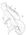
Fig. 7 A and 7B show the impeller blade with winglet;
Fig. 8 A-8C shows feasible winglet configurations;
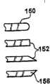
Fig. 8 D shows feasible winglet edge geometries;
Fig. 9 A-9D shows the end elevation of impeller blade, further shows winglet configurations;
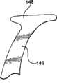
Figure 10 A and 10B show the blade that has groove around the blade near-end;
Figure 11 is the photo of molded polymer impeller;
Figure 12 has shown the load-deformation curve of impeller blade material; With
Figure 13 and 14 has shown the function relation between standard average flow fluid shear stress and tip clearance size.
Embodiment
Impeller according to one embodiment of the invention comprises wheel hub and the blade that at least one is supported by wheel hub.Embodiments of the invention comprise impeller, and described impeller has at least one flexible blade, and described impeller has deployment configuration that blade extends away from wheel hub and impeller by the storage construct of radial compression.For example, blade can be folded up towards wheel hub, and is remained there by the storage sleeve such as metal tube or sleeve pipe.In storage construct, more close wheel hub when blade far-end ratio is in deployment configuration, radius can obviously reduce, for example less than half of the radius of deployed condition.But sleeve can comprise non-expansion and expansion, and impeller is stored in non-expansion, and impeller can move to deployable part in order to launch.But impeller is in the inner expansion of the expansion of sleeve.
Can comprise according to impeller of the present invention a plurality of blades that are arranged to blade row.Blade row is spaced apart along wheel hub, and each blade row comprises one or more blades.For example, each blade row can comprise two or three blades.By a plurality of blade rows are set, rather than the single linear leaf around the wheel hub bending for example is set, more is conducive to realize storage construct.Single linear leaf is difficult to towards wheel hub folding more.
Embodiments of the invention can also comprise sleeve, and at least a portion of impeller is positioned at sleeve inner, and when vane rotary, flow is crossed sleeve.Sleeve can be extendible, and sleeve has extended architecture and the impeller storage construct when storage construct of impeller when deployment configuration.Sleeve can play the effect that impeller is constrained in storage construct.As selection, independent storage sleeve also can be set, when releasing the storage sleeve, impeller and can expand sleeve and both expand.Can expand sleeve and can comprise metal framework, for example comprise marmem.Elastic thin polymer film can be arranged on metal framework.Impeller blade has winglet at the blade far-end, and winglet and sleeve provide the fluid bearing to vane rotary.For example, sleeve can have drum type inner surface, and impeller rotates in described drum type inner surface, flow is crossed sleeve, when vane rotary, the motion of the winglet of each blade next-door neighbour drum type inner surface, the fluid between winglet and drum type inner surface forms the fluid bearing to vane rotary.
Impeller can be stored in the storage sleeve, launches in fluid hose, and when vane rotary, flow is crossed this fluid hose.The diameter of storage sleeve is approximately equal to or less than half of fluid hose diameter.The storage sleeve can be metal tube, and before launching, impeller is stored in this metal tube.Fluid hose can be the part of public pipe (water, gas, sewage etc.), bodily conduit (for example blood vessel), the propulsion unit that is used for the traffic tool or other structure that fluid can flow through.Impeller in storage construct can be transported to desired locations, then self-deploys to expansion, deployed condition.Storage construct is conducive to impeller is transported to desired locations, can pass through the opening less than deployed condition diameter.
Fluid hose can be the extend type of storage sleeve, and the expansion of storage sleeve allows impeller to launch.In this case, need not impeller is released sleeve to realize deployment configuration.For example, the impeller according to an example of the present invention can have in larger-diameter pipe by the little hole insertion that enters under storage construct.By utilizing live axle that impeller is shifted out, can launch impeller from the storage sleeve.Then the strain energy that is stored in blade material of impeller utilization extends to deployed condition.
The rotation of impeller can also make blade structure change to the operation structure.Impeller can have flexible blade, and when rotation under the design load operating mode and operation, described flexible blade is deformed into best fluid dynamic shape.
Embodiments of the invention comprise the impeller with at least one blade, and blade has winglet.Under running state, winglet can improve the hydrodynamic performance of impeller, reduces the shearing stress that is present in internal fluid.Impeller can comprise a plurality of blades of being convenient to be folded to store status.Blade can be arranged to a plurality of blade rows, compares with folding individual blade along one section similar distance of wheel hub extension, and this is convenient to make leaf folding to store status.Blade and (optional) wheel hub can be made of low-modulus material, for example polymer.Impeller can be unitary structure, and blade and impeller are formed by same material, for example form by molded polymer.
Also help fluid head or the pressure rising of input bigger numerical with the impeller of a plurality of blade rows.Ratio speed according to aial flow impeller of the present invention can be equal to mutually with the ratio speed of mixed flow pump.
Impeller can at the folded state Inserting Tube, launch subsequently.When impeller launched in fluid flow pipe, impeller can further be deformed into the operation structure, and at this moment, fluid is pumped under the drive of vane rotary.When the impeller end of run, impeller can be for example returned storage construct by folded flexible blade again by radial compression, and takes out less than the hole that enters of fluid hose or deployment configuration by diameter.For example, can again fold blade, by means of the rotary drive shaft of adhering to or checkrow wire, impeller be put to cylindrical storage cavity.
Can move in low reynolds number pipe flow according to impeller of the present invention, wherein pipe boundary layer comprises that the major part in pipe flows.Compare with pump with conventional impellers, the reynolds' number that relatively flows on blade is low.
Can optimize impeller, to move in non-Newtonian fluid.Can optimize impeller, with operation (for example emulsion drop, cell etc.) in comprising the fluid of fine granular, these fine granulars can be destroyed because of the excessive shearing stress that is subject in fluid.Impeller can be designed so that operation structure reaches best, and is not necessarily identical with deployment configuration under zero load.
When in storage construct, the impeller with impression has the internal mechanical stresses that has reduced in blade interior around root of blade in wheel hub.Impression can also be used to further reduce the fluid shear stress of being induced by the impeller of running state.
Blade can by polymer material for example polyurethane form.Can use the polymer with 10,000psi modulus, for example polyurethane.In some example, blade can have the hardness that is approximately equal to thick rubber ring.Therefore, impeller has certain hardness, but can distortion under performance load.For example, can selection material so that have allow predictable deformation under load to the linear modulus of operation stress and be used for the nonlinear modulus to higher stress of leaf folding to storage construct.
Figure 1A has shown the impeller that is in deployment configuration, and impeller compriseswheel hub 10 and such as the blade of blade 12.Impeller has the radius R of measuring to outmost vane tip from the central long axis of wheel hub1Also shown fluid flow sleeve 14 in figure, fluid-phase flows through this fluid flow sleeve 14 for impeller.Impeller can be used as axial-flow pump, fluid is passed the sleeve pumping.As selection, impeller can also be with the power supplying apparatus that acts on the traffic tool.For example, impeller can provide power for ship or other water craft such as jet boat, and sleeve is the pipe that is immersed in traffic tool water on every side.In this structure, blade launches.
Figure 1B has shown the impeller that is in storage construct, andblade 12 is folding or carry out other distortion towards wheel hub 10.Radius R2Less than the radius R shown in Figure 1A1
Impeller according to one embodiment of the invention has flexible blade, and described flexible blade can be folded into, and impeller is approximately equal to or less than half at the diameter of running state of impeller at the maximum diameter of folded state.With reference to Figure 1A and 1B, this is equivalent to R2≈≤(R1/ 2).
Fig. 2 shows the sketch of the expansion of impeller.Impeller haswheel hub 20 and blade (for example 22), and impeller is kept bystorage sleeve 24 with storage construct.Turningaxle 30 is used for drives impeller.This figure also shown at the checkrow wire of turning axle inside (guide wire) 28, and described checkrow wire 28 can be used for the location impeller, also can help to release impeller from the storage sleeve.The storage sleeve can be metal tube for example.The rotation of axle is the auxiliary impeller that launches also, for example, if the internal surface of storage sleeve has worm structure, impeller is reversed out the storage sleeve.On the left side has shownfluid hose 26, and when impeller launched and rotate, flow was crossed thisfluid hose 26.
The impeller that is in storage construct can be stored in the cylindrical cavity that is approximately equal to or is formed less thanhalf storage sleeve 24 offluid hose 26 diameters by diameter.
The storage sleeve can be metal tube, and before launching, impeller is stored in wherein.Fluid hose 26 is any structure that fluid can be flowed through with respect to impeller, for example flexible pipe or bodily conduit.Impeller in storage construct can in the fluid hose internal transmission to desired locations, then self-deploy to expansion, deployed condition.Storage construct allows the area of impeller process when being plunderred out by blade rotary less than the opening of deployed condition area.
As selection,fluid hose 26 can be the extend type ofstorage sleeve 24, and the expansion of constraint sleeve allows impeller to launch.In this case, impeller does not need to release sleeve to realize deployment configuration.For example, impeller can pass through to insert in fluid hose than aperture, for example the hole in smaller branch pipe or tube wall.Then by utilizing live axle that impeller is shifted out, can launch impeller from the storage sleeve.The strain energy that utilizes blade to store when storage construct can be in the situation that launch without any the external energy input.
Fig. 3 A further shows the impeller that is in storage construct, has shown blade andwheel hub 30 such as blade 34.Blade is kept leaning against on wheel hub foldedly by storage sleeve 36.Fig. 3 B has shown the impeller of releasing and self-deploying from the storage sleeve.As what more clearly can see in deployed condition, impeller has two row's blades, and first row comprisesblade 34, and second row comprises blade 32.
The impeller that Fig. 4 shows compriseswheel hub 60 and a plurality of blade, and blade has shown deployment configuration and operation structure.Deployment configuration is unloaded lower blade structure, and the operation structure is the structure of impeller when rotating with the operation rotational speed.The blade that shows deployment configuration with 62A, 64A and 66A.When under load, when for example rotating in fluid, deformable blade to blade is the operation structure of 62B, 64B and 66B.The rotation of impeller makes blade structure change to the operation structure from deployment configuration (zero load).When rotation under the design load operating mode and operation, flexible blade can be deformed into best fluid dynamic shape.
Fig. 4 has compared the blade shape of expansion and the blade shape of operation.Concerning the wheel hub and blade that are formed by identical polymer, simulation shows, when root rotated with respect to the first blade row, wheel hub is the mode deflection a little to rotate also when the second blade row.Generally speaking, blade is deflection forward, and the rising of blade makes their generation thrust, namely points to the power in the left side of this figure, and this power makes blade move towards the right side of this figure.The leading edge of the second blade row has been blocked.Have two blade rows, each is with two identical blades.
Can utilize criterion calculation hydrodynamic analysis (CFD), make blade shape optimization.But traditionally, non-rotating, unloaded structure is best.(if impeller can not be expanded, and expansion shape is the shape of impeller when not rotating, and does not have storage construct).Improved impeller has best operation structure, and improving one's methods of design impeller comprises optimization operation structure.Structure Calculation is determined under load from the EE Error Excepted of deployed condition distortion.
Fig. 5 shows the blade wheel structure with low reynolds number.Impeller comprises wheel hub 80 and two row's blades, and every row has two blades.First row comprises blade 82 and 84, and second row comprises blade 86 and 88.
This legend has shown the design element of low reynolds number impeller, and wherein the boundary layer thickness on fluid pipe walls is the same with caliber thick.Impeller has highly crooked costa and trailing edge line, on these lines, according to the local value of relative flow angle, adjusts blade pitch angle.The second row blade has groove shape structure, and this structure has the spiral path from the leading edge to the trailing edge.This is the cause due to leaf exhibition load change, and permission is used the axial-flow pump of this impeller to reach and is similar to mixed flow pump head rising (head rise).Load in the middle of the blade and blade exhibition is higher, causes producing this structure.The second row blade can further be divided into two blade rows that separate, and is although this structure can occur, so unobvious.
Fig. 6 A and 6B show respectively end elevation and the side view of impeller.Impeller comprises:wheel hub 100; The first row blade that comprisesblade blade blade
For the mixed-flow impeller of similar performance, hub diameter is usually very large, therefore, can not be folded into half storage diameter of deployed diameter.
Fig. 7 A and 7B have shown side view and the end elevation ofblade 120, andblade 120 haswinglet 122 at far-end.Fig. 7 A has shown the distal cross section of blade with dashed line.Fig. 7 B has shown the winglet that next-door neighbour's fluid flow sleeve internal surface moves, and this structure can be used as the fluid bearing of impeller.
Impeller can have at least one blade with winglet.In some embodiments, all blades of blade row inside all comprise winglet; Other blade can have or not have winglet.Winglet can improve the hydrodynamic performance of impeller.Winglet can also reduce the shearing stress that exists in fluid, for example lowers the degraded of biological structure (for example may reside in the cell of internal fluid).
Fig. 8 A-8C has shown feasible winglet configurations.Impeller blade has a pair of relative face usually: when blade rotates in fluid, inducing fluid passes the pressure side of pressure relative movement; With the suction surface by the motion of suction effect inducing fluid.Blade also has leading edge, trailing edge and the outer rim (this outer rim also can be called as vane tip or blade remote edge) of cutting fluid when blade rotary.Winglet is supported by outer rim or vane tip, has air foil shape.As shown in the figure, the suction side of blade on the right, on the left side on the pressure side.
Fig. 8 A has shown suction side winglet, andwinglet 142 extends from the suction side ofblade 140 outer rims.This is that like this, blade rotates towards observed direction from the viewgraph of cross-section of leading edge observation.Fig. 8 B has shownpressure side winglet 146, and its pressure side from blade 144 extends.Parameter can be similar to suction side winglet.The function of pressure side winglet is to reduce flowing by this gap.Have the effect of less formation hydrodynamic bearing, but pressure side winglet prevents that from fluid hose internal surface " scraping " low-momentum fluid this fluid from entering this gap and then being used for the core in tip whirlpool.This can reduce the shearing stress in the Fluid Flow in A main body.
Fig. 8 C shows combined winglet, and it is from pressure and the suction both sides extension of outer rim.Embodiments of the invention comprise the structure shown in Fig. 8 A-8C.Useful numerical method designs winglet configurations.In the place that length is long and blade has obvious helicity of chord of foil, it is complicated that the geometrical construction of vane tip and winglet and shape can become.
Fig. 8 D has shown operable possible winglet edge geometries.The figure illustrates roundededges 150,edge 152 and chisel edge 154,156 that profile is distinct.
Fig. 9 A-9D further shows winglet configurations, and the blade that supports winglet keeps identical shape in these examples.Fig. 9 A shows the outer rim of theblade 160 that there is no winglet.
Fig. 9 B has shown the pressure side winglet on the pressure side of extending the outer leafs edge, and it extends on part 164.Thepart 162 of winglet is equivalent to the blade original outer edge area shown in Fig. 9 A.
Fig. 9 C has shown suction side winglet, andpart 166 is extended from the suction side of blade outer rim, andpart 168 is equivalent to the original outer edge from blade.In an embodiment of the present invention, the radius on the pressure side of blade is approximately 1/3 to 1/2 of vane thickness or width.The scope of winglet can be 1/2 to 3 times of vane thickness.The thickness that shows is approximately equal to vane thickness.Winglet mainly be positioned at as shown in the figure the blade downstream half.Purpose is that the place that nestles up the fluid hose internal surface of blade operation outside winglet forms hydrodynamic bearing.Flow strength in the gap reduces, and seldom forms tip whirlpool.This has reduced the shearing stress in the fluid.This gap can for the base blade maximum ga(u)ge approximately 10% to approximately between 25%.The gap is the surface that is in substantially parallel relationship to the housing pipe.It can be cylindrical shape, taper shape or curved side cylinder, and wherein radius is the function of the axial position of blade element.Be used on the pressure side and the parameter of combination (as described below) winglet can be similar.
Thepart 170 that Fig. 9 D shown the combination pressure side of extending from the pressure side of blade and suction surface and suction side winglet, extend from pressure side, thepart 174 of extending from suction surface and thepart 172 that is equivalent to the original outer edge of blade.
Winglet is preferably the level and smooth shape of aerodynamics.Winglet has the leading edge of impact flow winglet edge and the trailing edge that flows and discharge from winglet surfaces.Usually in the direction of average flow, winglet preferably has level and smooth aerodynamic cross sections, and the direction of this average flow is parallel to the flow direction along blade tip surfaces.
Figure 10 A and 10B show the impression device of next-door neighbour's blade base, are groove at this.Figure 10 A shown bygroove 182 around blade 180.Groove is formed inwheel hub 184, and is arranged essentially parallel to blade proximal edge and next-door neighbour's blade proximal edge, and the proximal edge of blade is extended on every side in the blade base that blade connects wheel hub.Figure 10 B is sectional view, has showngroove 182 and blade 180.Impression also can be called as " dillet ".
Near the impression of root of blade, the groove around some or all of roots of blade for example, can help to reduce blade in storage construct, when for example folding leans against on wheel hub the internal mechanical stresses on blade.Impression can also be used to reduce the fluid shear stress in running state.
Figure 11 is the photo of impeller, and it is molded as the structure according to the embodiment of the present invention.This impeller is the polyurethane impeller that takes out from mould, and impeller has each with two blade rows of three blades.
Figure 12 is the strain-stress relation figure of nonlinear material, and this nonlinear material can be used for forming according to impeller of the present invention.The left side (low stress) and the right (heavily stressed) round dot correspond respectively to impeller operating point and storage condition.Stress/strain relation on the impeller operating point is roughly linearity.Impeller folding leans against storage condition on wheel hub within the high strain non-linear partial of material property curve.This allows in the situation that do not realize storage construct to tension fracture point.In the example of impeller, the maximum material rate elongation in storage construct is approximately 75%.
Preferably, nonlinear material is used for blade.Blade material can be harder under performance load, and same material for example may be soft in storage condition at leaf folding under high strain.For example, strain may be 10% under performance load, and is 75% when folding; Stress/strain curves has high-modulus (for example 10000) in performance load, to folding relevant high loading under have low modulus (for example 1000).Load-deformation curve can have the zone of two substantial linear, and break is between operating point and folding point strain.
Figure 13 and 14 shows the optimization to the fluid shear stress of example impeller.The internal surface of the far-end next-door neighbour cylindrical sleeve of impeller blade moves, and the tip clearance between blade far-end and sleeve diameter is approximately the 10-50% of the maximum ga(u)ge of blade far-end.
These curves are by double normalized, and design point values is both 1.0, and scale is regarded the percentage of design discharge and the factor multiple of design point stress value as.For example, Figure 13 demonstration, at 70% place of design discharge, shearing stress is 1.3 times of design conditions numerical value.Figure 14 shows, with the less factor, tip clearance is less, and shearing stress is higher, and this gap is larger, and stress is less.So, in the situation that have no significant effect pumping efficiency, can reduce fluid shear stress.
Can be compressed and packaged in the storage sleeve according to embodiment's impeller, for example metal tube, conduit, or be used for inserting other structure of object.For the object such as live subject, the storage sleeve diameter can be approximately three to four millimeters or less.After inserting this equipment, impeller can be expanded to geometrical construction in the original place, and the diameter of this geometrical construction is approximately six to seven millimeters.The flexible drive shaft that then can utilize the external drive motor with the object outside to be coupled, rotary blade.Can insert with store status according to impeller of the present invention, then be expanded to extended architecture (with respect to store status), and can be as 4 liters of for example medical assist pumpings per minute.In the representative example of this equipment, impeller is with about 30, the rotation of 000RPM rotating speed.Impeller can comprise the blade of the two or more one-tenth air foil shapes that form axial-flow pump.Impeller can utilize checkrow wire to locate, and utilizes the flexible shaft rotation.Checkrow wire can extend the hollow centre of flexible shaft is inner, and hollow centre can also be carried salt solution or is used for other fluid of dipping, cooling and/or lubrication applications.If necessary, can remove checkrow wire.The intubate that utilization has a 3-4mm diameter can realize implanting does not need operation in live subject.Implant for medical science, can use the live axle that comprises metal braid or polymer or composite material braided fabric, the live axle diameter can be about 11/2To 2 millimeters, live axle can be hollow, passes through to allow checkrow wire.
In a further embodiment, but sleeve has expansion and non-expansion.Impeller is stored in non-expansion, in order to insert.When impeller is positioned at or during near desired locations, impeller is pushed into expansion from the non-expansion of sleeve.The interior elastic energy inducer impeller inducer of flexible blade that is stored in impeller self-deploys, but and induces the sleeve expansion to expand.Then the sleeve of expansion can be played the part of the role of fluid flow pipe, and when vane rotary, flow is crossed this fluid flow pipe.Can expand sleeve and can comprise metal or polymer mesh thing or textile fibre and level and smooth sheath, so that flexible, extendible pipe to be provided.
Sleeve can be expanded and the reticulated work that is formed by flexible materials such as polymer, metal or other material can be comprised.In an example, reticulated work is made by nitinol, memory alloy.Utilize laser beam cutting thickness to be about thin plate or the metal cylinder barrel of mil-inch, in order to stay reticular structure.As selection, reticulated work can be formed by polymer.Other suitable material that is used for reticulated work comprises other metal (alloy that for example comprises memory alloy), polymer etc.Then coating, for example elastic coating are set on reticulated work.For example, can use elastomeric polymer, for example EstaneTM(EstaneTM), perhaps other polyurethane.
Therefore, can expand sleeve and can comprise reticulated work, matrix of woven wires for example, perhaps with the machine-processed metal cylinder barrel in the laser beam cutting space of the spacing between the expression line, other material that perhaps extends in vertical direction when a Direction distortion.Reticulated work can be covered by elasticity (elastane) film, the fluid flow pipe of crossing to form flow.Reticulated work can form cylinder barrel, and the inlet opening of flowing is at far-end, and the tap hole that flows is at near-end, and near-end is near the insertion point of object (for example pipe or live subject).When length sleeve shortens, for example utilize checkrow wire, cylinder barrel extends to larger diameter, allows larger flow velocity.Sexangle crystal cell base structure or other structure can be used for reticulated work.For example coating (for example biocompatible, corrosion resistant or improvement is flowed) can be coated on sleeve by solution film casting method.
Can select the reticulated work of sleeve or the direction of textile fibre, to allow to realize two kinds of stable structures, i.e. storage construct and deployment configuration.Be designed in an example of store status implantation object, the sleeve expanded that is in deployment configuration is approximately 20-30cm length, diameter is approximately 6-7mm.This diameter allows higher rate of flow of fluid and reduces friction pressure loss.In storage construct, but expansion with respect to the aboutprolongation 30% of deployment configuration, diameter is approximately 3mm.The decline of this assembly (far-end) comprises second group of opening and plate, to form entrance or to be used for the opening that the fluid of pumping is wanted in injection.Sleeve can also be provided for the guide wire attachment openings of fluid expulsion.Short (for example 1cm) of sleeve part can comprise the linear element (fin) that is arranged in around the sleeve central axis line, and fluid is discharged by sleeve.Fin can serve as stationary stator blades, removes vortex velocity from the impeller discharge currents.Fin can manufacture airfoil cross-section.Comprise the collapsible fire hose with the integral type suction booster, collapsible propulsion device in the impeller purposes that can expand the sleeve inner expansion, be used for biomedical pump of biofluid etc.
Can design impeller blade design, in order to minimize the destruction (for example emulsion drop, suspended matter, such as biological structure of cell etc.) of the fine granular of convection cell inside.Simulate with the CFD model shearing stress that particle stands through simulated impeller the time.The time integral of the middle shearing stress that particle stands is used to provide the estimated probability of cytoclasis in biomedical applications.Have a plurality of blade rows as above the splitterr vanes structure decrease cell stay in the middle of waiting time in the shearing stress zone, compare with the conventional impellers design, allow advantageously to reduce the destruction of cell or other particle.
When impeller during in store status, impeller blade can occupy 95% of impeller compression volume for example.Blade can form by have material that enough restoring forces are expanded, resilient, that springy or other is with resilience when ejecting sleeve.In other example, but blade can be by other flexible polymer, compressible or deformablely comprise that the material of metal forms with the expandable foam of skin or other alternatively.
Except long, continuous helical blade, also can have the blade that multicomponent is opened according to the impeller of the embodiment of the present invention.The typical impeller of prior art has continuous, long helical blade, and this blade is difficult to lean against on wheel hub to be folded up.By a linear leaf is divided into two or three shorter parts, blade can be folded in cylindrical volume or space more easily, easily launches when suitably locating subsequently.The quantity of blade row can be one, two, three, four, five or more.The torsion angle of pitch is variable.
A kind of method of Impeller Design provides two blade impellers, and it is with present the blade of the coiling of obvious degree around center hub.But the 3D shape of blade has limited blade can be in the situation that degree indeformable or that fracture is folding.Present minimum two rows that reel, three row's (or may be more) blades by individual blade row is divided into around wheel hub, make blade have the above shape of two dimension, allow during storing process crooked more easily.The combination of three or two blade rows can produce flow and the pressure identical with single blade row.Axial-flow pump is designed with two blade rows, and CFD (computation fluid dynamics) the analysis showed that, this pump structure is applicable to the medical science secondary purpose.Model is made of the flexible polyurethane material, and it can successfully be folded in metal sleeve.
Impeller can be used for having flowing very much of low reynolds number, for example, and with low speed or the sticking fluid of low flow velocity pumping.The minimum wing pump that diameter is approximately 6mm can by polymers manufacturing, take out from precision die.This permission can be with unusual low-cost production impeller.The use of polymer blades allows in the situation that the mould locking is taken out pump impeller from mould, and allows to replace many parts mould or flatten die with the single-piece mould.This is very favorable concerning a small amount of biofluid of pumping.Impeller also can be used for having flowing of typical reynolds' number.Impeller diameter also can be in the scope of several inches to several feet.
The purposes of described improvement Impeller Design comprises the pump for chemical engineering, the propulsion device that is used for aviation or marine vessel, water pump etc.It is all useful that improved Impeller Design will be stored in compactly designed any purposes to impeller.Impeller can be formed by tinsel, plastics and non-elastic material, for example in collapsible constructions.Expansion can comprise that use motor or other mechanical device launch blade, Automatic-expanding etc. under the inducing of centrifugal force.Example of the present invention comprises can be positioned at subject so that the device of pumping fluid, this installs to be in has in the insertion structure insertion objects that inserts cross section, this installs to have the operation that moves cross section and is configured in the object internal operation, wherein moves cross section greater than inserting cross section.Operation diameter (the inswept maximum diameter of a circle of its outer rim during the impeller blade rotation) can be larger more than 50% than the insertion diameter of impeller, can be larger more than 100% than inserting diameter.
The present invention is not limited to illustrative example as above.These examples are not as limitation of the scope of the invention.Method described herein, equipment, composition etc. are all exemplary, not as limitation of the scope of the invention.It may occur to persons skilled in the art that change or other use to this.Scope of the present invention is by the circumscription of claims.
The patent of mentioning in this specification, patent application or publication are hereby incorporated by, thus just as each file particularly with show seriatim to be incorporated herein by reference the same.The totality of the U.S. Provisional PatentApplication sequence number 60/610,938 of particularly, submitting on September 17th, 2004 is incorporated herein.
Claims (26)
1. induce equipment for one kind, be used for inducing fluid with respect to this equipment moving, this equipment has impeller, and this impeller comprises:
Wheel hub; With
By a plurality of blades that wheel hub supports, each described blade has near-end and the far-end that is attached to wheel hub,
Described blade is arranged to blade row along wheel hub, and each blade row comprises at least one blade;
Described impeller has deployment configuration and storage construct, and each blade that is in the deployment configuration of impeller extends away from wheel hub, and each blade of storage construct that is in impeller is compressed in order to move the far-end of each blade towards wheel hub;
Described impeller can operate to self-deploy to deployment configuration from storage construct, and the strain energy of being stored by each blade of storage construct that self-deploys of impeller drives.
2. the equipment of inducing as claimed in claim 1, wherein, each blade row comprises two blades.
3. the equipment of inducing as claimed in claim 1, wherein, impeller comprises two blade rows, each blade row comprises two blades.
4. the equipment of inducing as claimed in claim 1, also comprise sleeve, and at least a portion of impeller is positioned at sleeve inner, and when vane rotary, flow is crossed sleeve.
5. the equipment of inducing as claimed in claim 4, wherein, sleeve is extendible, sleeve has the extended architecture when impeller is in deployment configuration.
6. the equipment of inducing as claimed in claim 4, wherein, sleeve has: non-expansion, wherein impeller is in storage construct; But with expansion, wherein impeller is in deployment configuration.
7. the equipment of inducing as claimed in claim 1, wherein, each blade has winglet at the blade far-end.
8. the equipment of inducing as claimed in claim 1, wherein, impeller comprises unitary impeller body, described unitary impeller body comprises described wheel hub and described a plurality of blade.
9. the equipment of inducing as claimed in claim 1, wherein impeller also has the operation structure that blade is obtained from the deployment configuration distortion when being in the vane rotary of deployment configuration.
10. induce equipment for one kind, be used for inducing fluid with respect to this equipment moving, this equipment has impeller, and this impeller comprises:
Wheel hub; With
By the blade that wheel hub supports, described blade is made by polymer and is had near-end and a far-end that is attached to wheel hub,
Described impeller has deployment configuration and storage construct, and the blade that is in the deployment configuration of impeller extends away from wheel hub, and the blade of storage construct that is in impeller is compressed so that towards the far-end of wheel hub moving blade,
Described impeller can operate to self-deploy to deployment configuration from storage construct, and the strain energy of being stored by each blade of storage construct that self-deploys of impeller drives,
Polymer has for being in deployment configuration when impeller and in the first modulus of performance load lower blade distortion be used for compression blade so that impeller is in the second modulus of storage construct, the first modulus is about ten times of the second modulus.
11. the equipment of inducing as claimed in claim 10, wherein, polymer is the polyurethane of low flexural modulus.
12. induce equipment for one kind, be used for inducing fluid with respect to this equipment moving, this equipment has impeller, and this impeller comprises:
Wheel hub; With
By the blade that wheel hub supports, described blade has near-end and the far-end that is attached to wheel hub,
Flexible shaft with first end and second end is coupled the first end of flexible shaft and turbomachine,
Described impeller has deployment configuration and storage construct, and the blade that is in the deployment configuration of impeller extends away from wheel hub, and the blade of storage construct that is in impeller is compressed so that towards the far-end of wheel hub moving blade,
Described impeller can operate to self-deploy to deployment configuration from storage construct, and the strain energy of being stored by each blade of storage construct that self-deploys of impeller drives,
Impeller rotates under the effect of the torque of the second end that puts on flexible shaft.
13. induce equipment for one kind, be used for inducing fluid with respect to this equipment moving, this equipment has impeller, and this impeller comprises:
Wheel hub; With
By the blade that wheel hub supports, described blade has near-end and the far-end that is attached to wheel hub,
Described impeller has deployment configuration and storage construct, and the blade that is in the deployment configuration of impeller extends away from wheel hub, and the blade of storage construct that is in impeller is compressed so that towards the far-end of wheel hub moving blade,
Impeller can operate to self-deploy to deployment configuration from storage construct, and the strain energy of being stored by the blade of storage construct that self-deploys of impeller drives.
14. the equipment of inducing as claimed in claim 13, wherein, this equipment is the axial-flow pump for liquid.
15. the equipment of inducing as claimed in claim 13, wherein, impeller has the monomer-type polymer body that comprises wheel hub and blade.
16. induce equipment for one kind, be used for inducing fluid with respect to this equipment moving, this equipment has impeller, and this impeller comprises:
Wheel hub with outer surface;
Blade, described blade have the near-end, first surface of the outer surface that is attached to wheel hub and second;
Be formed in the outer surface of wheel hub, parallel to and adjacent in the first groove of the near-end of blade first surface;
Be formed in the outer surface of wheel hub, parallel to and adjacent in the second groove of the near-end of second, blade;
Described impeller has deployment configuration and storage construct, and the blade that is in the deployment configuration of impeller extends away from wheel hub, and the blade of storage construct that is in impeller is compressed so that towards the far-end of wheel hub moving blade,
Described impeller can operate to self-deploy to deployment configuration from storage construct, and the strain energy of being stored by each blade of storage construct that self-deploys of impeller drives.
17. the equipment of inducing as claimed in claim 16, wherein,
Blade is flexible,
Described the first groove and described the second groove are conducive to make the blade far-end to move towards wheel hub, in order to obtain storage construct.
18. induce equipment for one kind, be used for inducing fluid with respect to this equipment moving, this equipment has impeller, and this impeller comprises:
Wheel hub with outer surface;
With described wheel hub all-in-one-piece blade, described blade has air foil shape and is attached to the near-end of the outer surface of wheel hub,
Be formed in the outer surface of wheel hub, parallel to and adjacent in the groove of the bending of blade near-end,
Described impeller has deployment configuration and storage construct, and the blade that is in the deployment configuration of impeller extends away from wheel hub, and the blade of storage construct that is in impeller is compressed so that towards the far-end of wheel hub moving blade,
Described impeller can operate to self-deploy to deployment configuration from storage construct, and the strain energy of being stored by each blade of storage construct that self-deploys of impeller drives.
19. induce equipment for one kind, be used for inducing fluid with respect to this equipment moving, this equipment has impeller, and this impeller comprises:
Wheel hub; With
By the flexible blade that wheel hub supports, described blade has the near-end that is attached to wheel hub, far-end, first surface and second, and the far-end of described blade has the winglet that extends from described first surface;
Described impeller has deployment configuration and storage construct, and the blade that is in the deployment configuration of impeller extends away from wheel hub, and the blade of storage construct that is in impeller is compressed so that towards the far-end of wheel hub moving blade,
Described impeller can operate to self-deploy to deployment configuration from storage construct, and the strain energy of being stored by the blade of storage construct that self-deploys of impeller drives.
20. the equipment of inducing as claimed in claim 19, wherein, this equipment is the axial-flow pump for liquid.
21. the equipment of inducing as claimed in claim 19, wherein, this equipment provides power for the traffic tool.
22. the equipment of inducing as claimed in claim 19, wherein, described impeller comprises:
A plurality of blades, each described blade have the near-end that is attached to wheel hub, first surface and second;
Parallel to and adjacent in the first groove of the near-end of each blade first surface,
Parallel to and adjacent in the second groove of the near-end of second, each blade.
23. the equipment of inducing as claimed in claim 19, wherein, impeller rotates in sleeve inner, and winglet and sleeve interior surface form fluid bearing.
24. the equipment of inducing as claimed in claim 19, wherein, first surface is the pressure side of blade.
25. the equipment of inducing as claimed in claim 19, wherein, first surface is the suction surface of blade.
26. the equipment of inducing as claimed in claim 19, wherein, winglet is also from second extension of blade.
Applications Claiming Priority (5)
| Application Number | Priority Date | Filing Date | Title |
|---|---|---|---|
| US61093804P | 2004-09-17 | 2004-09-17 | |
| US60/610,938 | 2004-09-17 | ||
| US11/227,277 | 2005-09-15 | ||
| US11/227,277US7393181B2 (en) | 2004-09-17 | 2005-09-15 | Expandable impeller pump |
| PCT/US2005/033416WO2006034158A2 (en) | 2004-09-17 | 2005-09-16 | Expandable impeller pump |
Publications (2)
| Publication Number | Publication Date |
|---|---|
| CN101278127A CN101278127A (en) | 2008-10-01 |
| CN101278127Btrue CN101278127B (en) | 2013-05-08 |
Family
ID=36074197
Family Applications (1)
| Application Number | Title | Priority Date | Filing Date |
|---|---|---|---|
| CN2005800312271AExpired - LifetimeCN101278127B (en) | 2004-09-17 | 2005-09-16 | Expandable impeller pump |
Country Status (6)
| Country | Link |
|---|---|
| US (9) | US7393181B2 (en) |
| EP (5) | EP3792499B1 (en) |
| JP (2) | JP4814244B2 (en) |
| CN (1) | CN101278127B (en) |
| AU (2) | AU2005286914B2 (en) |
| WO (1) | WO2006034158A2 (en) |
Cited By (1)
| Publication number | Priority date | Publication date | Assignee | Title |
|---|---|---|---|---|
| US9404505B2 (en) | 2008-12-05 | 2016-08-02 | Ecp Entwicklungsgesellschaft Mbh | Fluid pump with a rotor |
Families Citing this family (223)
| Publication number | Priority date | Publication date | Assignee | Title |
|---|---|---|---|---|
| US6889082B2 (en) | 1997-10-09 | 2005-05-03 | Orqis Medical Corporation | Implantable heart assist system and method of applying same |
| DE10336902C5 (en) | 2003-08-08 | 2019-04-25 | Abiomed Europe Gmbh | Intracardiac pumping device |
| US7416525B2 (en) | 2003-09-18 | 2008-08-26 | Myrakelle, Llc | Rotary blood pump |
| EP2151257B1 (en) | 2004-08-13 | 2013-04-17 | Delgado, Reynolds M., III | Apparatus for long-term assisting a left ventricle to pump blood |
| US7393181B2 (en) | 2004-09-17 | 2008-07-01 | The Penn State Research Foundation | Expandable impeller pump |
| CN102380135A (en) | 2006-03-23 | 2012-03-21 | 宾州研究基金会 | Heart assist device with expandable impeller pump |
| KR20090074110A (en) | 2006-03-31 | 2009-07-06 | 오퀴스 메디컬 코포레이션 | Rotary Blood Pump |
| US9028392B2 (en)* | 2006-12-01 | 2015-05-12 | NuCardia, Inc. | Medical device |
| GB2449218B (en)* | 2007-05-18 | 2009-04-15 | Jessal Murarji | Gas sampler for vapour detectors |
| US7828710B2 (en)* | 2007-06-05 | 2010-11-09 | Medical Value Partners, Llc | Apparatus comprising a drive cable for a medical device |
| US8079948B2 (en)* | 2007-08-29 | 2011-12-20 | NuCardia, Inc. | Article comprising an impeller |
| ATE480274T1 (en)* | 2007-10-08 | 2010-09-15 | Ais Gmbh Aachen Innovative Sol | CATHETER DEVICE |
| EP2047873B1 (en) | 2007-10-08 | 2010-12-15 | Ais Gmbh Aachen Innovative Solutions | Catheter device |
| US8489190B2 (en) | 2007-10-08 | 2013-07-16 | Ais Gmbh Aachen Innovative Solutions | Catheter device |
| US8439859B2 (en) | 2007-10-08 | 2013-05-14 | Ais Gmbh Aachen Innovative Solutions | Catheter device |
| JP5171953B2 (en) | 2008-06-23 | 2013-03-27 | テルモ株式会社 | Blood pump device |
| EP2341956B1 (en) | 2008-10-06 | 2015-12-23 | Indiana University Research and Technology Corporation | Methods and apparatus for active or passive assistance in the circulatory system |
| EP2372160B1 (en) | 2008-12-08 | 2014-07-30 | Thoratec Corporation | Centrifugal pump device |
| EP2216059A1 (en) | 2009-02-04 | 2010-08-11 | ECP Entwicklungsgesellschaft mbH | Catheter device with a catheter and an actuation device |
| JP5378010B2 (en) | 2009-03-05 | 2013-12-25 | ソラテック コーポレーション | Centrifugal pump device |
| CN102341600B (en) | 2009-03-06 | 2014-12-10 | 胸腔科技有限公司 | Centrifugal pump device |
| EP2229965A1 (en) | 2009-03-18 | 2010-09-22 | ECP Entwicklungsgesellschaft mbH | Fluid pump with particular form of a rotor blade |
| EP2246078A1 (en) | 2009-04-29 | 2010-11-03 | ECP Entwicklungsgesellschaft mbH | Shaft assembly with a shaft which moves within a fluid-filled casing |
| EP2248544A1 (en) | 2009-05-05 | 2010-11-10 | ECP Entwicklungsgesellschaft mbH | Fluid pump with variable circumference, particularly for medical use |
| EP2266640A1 (en)* | 2009-06-25 | 2010-12-29 | ECP Entwicklungsgesellschaft mbH | Compressible and expandable turbine blade for a fluid pump |
| CN102481398A (en) | 2009-07-01 | 2012-05-30 | 宾夕法尼亚州研究基金会 | Blood pump with expandable cannula |
| US8821365B2 (en) | 2009-07-29 | 2014-09-02 | Thoratec Corporation | Rotation drive device and centrifugal pump apparatus using the same |
| EP2282070B1 (en) | 2009-08-06 | 2012-10-17 | ECP Entwicklungsgesellschaft mbH | Catheter device with a coupling device for a drive device |
| EP2298371A1 (en) | 2009-09-22 | 2011-03-23 | ECP Entwicklungsgesellschaft mbH | Function element, in particular fluid pump with a housing and a transport element |
| EP2298373A1 (en) | 2009-09-22 | 2011-03-23 | ECP Entwicklungsgesellschaft mbH | Fluid pump with at least one turbine blade and a seating device |
| EP2298372A1 (en) | 2009-09-22 | 2011-03-23 | ECP Entwicklungsgesellschaft mbH | Rotor for an axial pump for transporting a fluid |
| EP2299119B1 (en)* | 2009-09-22 | 2018-11-07 | ECP Entwicklungsgesellschaft mbH | Inflatable rotor for a fluid pump |
| EP2314330A1 (en) | 2009-10-23 | 2011-04-27 | ECP Entwicklungsgesellschaft mbH | Flexible shaft arrangement |
| EP2314331B1 (en) | 2009-10-23 | 2013-12-11 | ECP Entwicklungsgesellschaft mbH | Catheter pump arrangement and flexible shaft arrangement with a cable core |
| US8690749B1 (en) | 2009-11-02 | 2014-04-08 | Anthony Nunez | Wireless compressible heart pump |
| EP2338540A1 (en) | 2009-12-23 | 2011-06-29 | ECP Entwicklungsgesellschaft mbH | Delivery blade for a compressible rotor |
| EP2338541A1 (en) | 2009-12-23 | 2011-06-29 | ECP Entwicklungsgesellschaft mbH | Radial compressible and expandable rotor for a fluid pump |
| EP2338539A1 (en)* | 2009-12-23 | 2011-06-29 | ECP Entwicklungsgesellschaft mbH | Pump device with a detection device |
| EP2347778A1 (en) | 2010-01-25 | 2011-07-27 | ECP Entwicklungsgesellschaft mbH | Fluid pump with a radially compressible rotor |
| EP2353626A1 (en) | 2010-01-27 | 2011-08-10 | ECP Entwicklungsgesellschaft mbH | Supply device for a fluid |
| JP5443197B2 (en) | 2010-02-16 | 2014-03-19 | ソラテック コーポレーション | Centrifugal pump device |
| KR101845213B1 (en) | 2010-02-17 | 2018-05-18 | 플로우 포워드 메디컬, 인크. | System and method to increase the overall diameter of veins |
| US9555174B2 (en) | 2010-02-17 | 2017-01-31 | Flow Forward Medical, Inc. | Blood pump systems and methods |
| US9662431B2 (en) | 2010-02-17 | 2017-05-30 | Flow Forward Medical, Inc. | Blood pump systems and methods |
| DE102010009581A1 (en)* | 2010-02-26 | 2011-09-01 | Danfoss A/S | Reverse osmosis device |
| EP2363157A1 (en)* | 2010-03-05 | 2011-09-07 | ECP Entwicklungsgesellschaft mbH | Device for exerting mechanical force on a medium, in particular fluid pump |
| JP5572832B2 (en) | 2010-03-26 | 2014-08-20 | ソーラテック コーポレイション | Centrifugal blood pump device |
| EP2388029A1 (en) | 2010-05-17 | 2011-11-23 | ECP Entwicklungsgesellschaft mbH | Pump array |
| EP2399639A1 (en) | 2010-06-25 | 2011-12-28 | ECP Entwicklungsgesellschaft mbH | System for introducing a pump |
| JP5681403B2 (en) | 2010-07-12 | 2015-03-11 | ソーラテック コーポレイション | Centrifugal pump device |
| EP2407186A1 (en)* | 2010-07-15 | 2012-01-18 | ECP Entwicklungsgesellschaft mbH | Rotor for a pump, produced with an initial elastic material |
| EP2407185A1 (en)* | 2010-07-15 | 2012-01-18 | ECP Entwicklungsgesellschaft mbH | Radial compressible and expandable rotor for a pump with a turbine blade |
| EP2407187A3 (en) | 2010-07-15 | 2012-06-20 | ECP Entwicklungsgesellschaft mbH | Blood pump for invasive application within the body of a patient |
| EP2422735A1 (en) | 2010-08-27 | 2012-02-29 | ECP Entwicklungsgesellschaft mbH | Implantable blood transportation device, manipulation device and coupling device |
| JP5577506B2 (en) | 2010-09-14 | 2014-08-27 | ソーラテック コーポレイション | Centrifugal pump device |
| WO2012051454A2 (en) | 2010-10-13 | 2012-04-19 | Thoratec Corporation | Pumping blood |
| US8597170B2 (en) | 2011-01-05 | 2013-12-03 | Thoratec Corporation | Catheter pump |
| US8485961B2 (en) | 2011-01-05 | 2013-07-16 | Thoratec Corporation | Impeller housing for percutaneous heart pump |
| WO2012094535A2 (en) | 2011-01-06 | 2012-07-12 | Thoratec Corporation | Percutaneous heart pump |
| WO2012094641A2 (en) | 2011-01-06 | 2012-07-12 | Thoratec Corporation | Percutaneous heart pump |
| EP2497521A1 (en) | 2011-03-10 | 2012-09-12 | ECP Entwicklungsgesellschaft mbH | Push device for axial insertion of a string-shaped, flexible body |
| EP2693609B1 (en) | 2011-03-28 | 2017-05-03 | Thoratec Corporation | Rotation and drive device and centrifugal pump device using same |
| EP2744539B1 (en) | 2011-08-17 | 2022-11-02 | Artio Medical, Inc. | System to increase the overall diameter of a peripheral artery |
| KR102062132B1 (en) | 2011-08-17 | 2020-01-03 | 플로우 포워드 메디컬, 인크. | Blood pump systems and methods |
| EP2564771A1 (en) | 2011-09-05 | 2013-03-06 | ECP Entwicklungsgesellschaft mbH | Medicinal product with a functional element for invasive use in the body of a patient |
| CA2849436A1 (en)* | 2011-09-20 | 2013-03-28 | Stephen E. Crane | Compressed gas energy storage system using turbine |
| US8926492B2 (en) | 2011-10-11 | 2015-01-06 | Ecp Entwicklungsgesellschaft Mbh | Housing for a functional element |
| US8864643B2 (en) | 2011-10-13 | 2014-10-21 | Thoratec Corporation | Pump and method for mixed flow blood pumping |
| EP2606920A1 (en) | 2011-12-22 | 2013-06-26 | ECP Entwicklungsgesellschaft mbH | Sluice device for inserting a catheter |
| EP2606919A1 (en) | 2011-12-22 | 2013-06-26 | ECP Entwicklungsgesellschaft mbH | Sluice device for inserting a catheter |
| EP2607712B1 (en) | 2011-12-22 | 2016-07-13 | ECP Entwicklungsgesellschaft mbH | Pump housing with an interior for holding a pump rotor |
| JP6083929B2 (en) | 2012-01-18 | 2017-02-22 | ソーラテック コーポレイション | Centrifugal pump device |
| JP2015505515A (en) | 2012-02-07 | 2015-02-23 | フリダヤ インコーポレーテッドHridaya, Inc. | Blood circulation assist device |
| US11389638B2 (en)* | 2012-02-07 | 2022-07-19 | Hridaya, Inc. | Hemodynamic assist device |
| JP6034889B2 (en) | 2012-03-05 | 2016-11-30 | ソーラテック コーポレイション | Modular implantable medical pump |
| US9446179B2 (en) | 2012-05-14 | 2016-09-20 | Thoratec Corporation | Distal bearing support |
| US9327067B2 (en) | 2012-05-14 | 2016-05-03 | Thoratec Corporation | Impeller for catheter pump |
| DE102013008158A1 (en) | 2012-05-14 | 2013-11-14 | Thoratec Corporation | Distal bearing carrier |
| GB2504177B (en) | 2012-05-14 | 2014-12-10 | Thoratec Corp | Sheath system for catheter pump |
| US9872947B2 (en) | 2012-05-14 | 2018-01-23 | Tc1 Llc | Sheath system for catheter pump |
| US8721517B2 (en)* | 2012-05-14 | 2014-05-13 | Thoratec Corporation | Impeller for catheter pump |
| EP4218887A1 (en)* | 2012-05-14 | 2023-08-02 | Tc1 Llc | Mechanical circulatory support device for stabilizing a patient after cardiogenic shock |
| CN108742951B (en) | 2012-06-06 | 2021-05-25 | 洋红医疗有限公司 | Artificial kidney valve |
| CN102748300A (en)* | 2012-06-29 | 2012-10-24 | 江苏国泉泵业制造有限公司 | Spiral axial-flow pump |
| CN102748322A (en)* | 2012-06-29 | 2012-10-24 | 江苏国泉泵业制造有限公司 | Double-vane axial flow pump |
| US9358329B2 (en) | 2012-07-03 | 2016-06-07 | Thoratec Corporation | Catheter pump |
| US9421311B2 (en) | 2012-07-03 | 2016-08-23 | Thoratec Corporation | Motor assembly for catheter pump |
| EP4186557A1 (en) | 2012-07-03 | 2023-05-31 | Tc1 Llc | Motor assembly for catheter pump |
| EP2692369B1 (en)* | 2012-07-31 | 2015-04-15 | Rheinisch-Westfälische Technische Hochschule Aachen | Axial flow blood pump device |
| US10258730B2 (en) | 2012-08-17 | 2019-04-16 | Flow Forward Medical, Inc. | Blood pump systems and methods |
| US10857274B2 (en) | 2012-11-06 | 2020-12-08 | Queen Mary University Of London | Mechanical circulatory support device with centrifugal impeller designed for implantation in the descending aorta |
| US12151092B2 (en) | 2012-11-06 | 2024-11-26 | Procardia Llc | Mechanical circulatory support device with centrifugal impeller designed for implantation in the descending aorta |
| EP2745869A1 (en) | 2012-12-21 | 2014-06-25 | ECP Entwicklungsgesellschaft mbH | Sluice assembly for the introduction of a cord-like body, in particular of a catheter, into a patient |
| US9371826B2 (en) | 2013-01-24 | 2016-06-21 | Thoratec Corporation | Impeller position compensation using field oriented control |
| US9556873B2 (en) | 2013-02-27 | 2017-01-31 | Tc1 Llc | Startup sequence for centrifugal pump with levitated impeller |
| CN103149149A (en)* | 2013-03-11 | 2013-06-12 | 北京矿冶研究总院 | High-temperature high-speed titanium fire-proof material characteristic test machine and test method |
| WO2014164136A1 (en) | 2013-03-13 | 2014-10-09 | Thoratec Corporation | Fluid handling system |
| EP4233702A3 (en) | 2013-03-13 | 2023-12-20 | Magenta Medical Ltd. | Manufacture of an impeller |
| US10583231B2 (en) | 2013-03-13 | 2020-03-10 | Magenta Medical Ltd. | Blood pump |
| US11077294B2 (en) | 2013-03-13 | 2021-08-03 | Tc1 Llc | Sheath assembly for catheter pump |
| US11033728B2 (en) | 2013-03-13 | 2021-06-15 | Tc1 Llc | Fluid handling system |
| US9144638B2 (en) | 2013-03-14 | 2015-09-29 | Thoratec Corporation | Blood pump rotor bearings |
| EP4190376A1 (en) | 2013-03-15 | 2023-06-07 | Tc1 Llc | Catheter pump assembly including a stator |
| US9308302B2 (en) | 2013-03-15 | 2016-04-12 | Thoratec Corporation | Catheter pump assembly including a stator |
| US10052420B2 (en) | 2013-04-30 | 2018-08-21 | Tc1 Llc | Heart beat identification and pump speed synchronization |
| US9713663B2 (en) | 2013-04-30 | 2017-07-25 | Tc1 Llc | Cardiac pump with speed adapted for ventricle unloading |
| EP2860849B1 (en) | 2013-10-11 | 2016-09-14 | ECP Entwicklungsgesellschaft mbH | Compressible motor, implanting assembly and method for positioning the motor |
| US9764113B2 (en) | 2013-12-11 | 2017-09-19 | Magenta Medical Ltd | Curved catheter |
| NL2012503C2 (en)* | 2013-12-24 | 2015-06-26 | Flowserve B V | RANGE FOR A PUMP OR TURBINE AND PUMP OR TURBINE WITH RANGE. |
| WO2015160980A1 (en)* | 2014-04-15 | 2015-10-22 | Thoratec Corporation | Heart pump providing adjustable out flow |
| EP3131599B1 (en) | 2014-04-15 | 2019-02-20 | Tc1 Llc | Catheter pump with access ports |
| WO2015160943A1 (en) | 2014-04-15 | 2015-10-22 | Thoratec Corporation | Sensors for catheter pumps |
| US10583232B2 (en) | 2014-04-15 | 2020-03-10 | Tc1 Llc | Catheter pump with off-set motor position |
| EP3131597B1 (en) | 2014-04-15 | 2020-12-02 | Tc1 Llc | Catheter pump introducer systems |
| US10293090B2 (en) | 2014-04-25 | 2019-05-21 | Yale University | Percutaneous device and method for promoting movement of a bodily fluid |
| EP3583973A1 (en) | 2014-08-18 | 2019-12-25 | Tc1 Llc | Guide features for percutaneous catheter pump |
| US9623161B2 (en) | 2014-08-26 | 2017-04-18 | Tc1 Llc | Blood pump and method of suction detection |
| WO2016086137A1 (en) | 2014-11-26 | 2016-06-02 | Thoratec Corporation | Pump and method for mixed flow blood pumping |
| WO2016118781A2 (en) | 2015-01-22 | 2016-07-28 | Thoratec Corporation | Motor assembly with heat exchanger for catheter pump |
| US9675738B2 (en) | 2015-01-22 | 2017-06-13 | Tc1 Llc | Attachment mechanisms for motor of catheter pump |
| US9770543B2 (en) | 2015-01-22 | 2017-09-26 | Tc1 Llc | Reduced rotational mass motor assembly for catheter pump |
| EP3256183B1 (en) | 2015-02-11 | 2025-08-13 | Tc1 Llc | Heart beat identification and pump speed synchronization |
| EP3256185B1 (en) | 2015-02-12 | 2019-10-30 | Tc1 Llc | System and method for controlling the position of a levitated rotor |
| US10371152B2 (en) | 2015-02-12 | 2019-08-06 | Tc1 Llc | Alternating pump gaps |
| EP3256184B1 (en) | 2015-02-13 | 2020-04-08 | Tc1 Llc | Impeller suspension mechanism for heart pump |
| US10350341B2 (en) | 2015-03-20 | 2019-07-16 | Drexel University | Impellers, blood pumps, and methods of treating a subject |
| US9907890B2 (en) | 2015-04-16 | 2018-03-06 | Tc1 Llc | Catheter pump with positioning brace |
| DK3288609T3 (en)* | 2015-04-30 | 2023-05-01 | Ecp Entw Mbh | ROTOR FOR A FLUID PUMP |
| US9616991B2 (en) | 2015-05-01 | 2017-04-11 | Peter Daniel WIRASNIK | Mechanically self-regulated propeller |
| WO2016185473A1 (en) | 2015-05-18 | 2016-11-24 | Magenta Medical Ltd. | Blood pump |
| EP3848089A1 (en) | 2015-09-14 | 2021-07-14 | Tc1 Llc | Fluid handling system |
| EP4290081A3 (en) | 2015-09-25 | 2024-02-21 | Procyrion, Inc. | Non-occluding intravascular blood pump providing reduced hemolysis |
| US10117983B2 (en) | 2015-11-16 | 2018-11-06 | Tc1 Llc | Pressure/flow characteristic modification of a centrifugal pump in a ventricular assist device |
| AU2017257508B2 (en) | 2016-04-29 | 2021-10-14 | Artio Medical, Inc. | Conduit tips and systems and methods for use |
| WO2018017716A1 (en) | 2016-07-21 | 2018-01-25 | Tc1 Llc | Rotary seal for cantilevered rotor pump and methods for axial flow blood pumping |
| US11160970B2 (en) | 2016-07-21 | 2021-11-02 | Tc1 Llc | Fluid seals for catheter pump motor assembly |
| EP3808401A1 (en) | 2016-07-21 | 2021-04-21 | Tc1 Llc | Gas-filled chamber for catheter pump motor assembly |
| US10660998B2 (en) | 2016-08-12 | 2020-05-26 | Tci Llc | Devices and methods for monitoring bearing and seal performance |
| EP3518825B1 (en) | 2016-09-29 | 2020-05-27 | Magenta Medical Ltd. | Blood vessel tube |
| US11524153B2 (en) | 2016-10-03 | 2022-12-13 | Queen Mary University Of London | Mechanical circulatory support device with axial flow turbomachine optimized for heart failure and cardio-renal syndrome by implantation in the descending aorta |
| US12090310B2 (en) | 2016-10-03 | 2024-09-17 | Procardia Llc | Mechanical circulatory support device with axial flow turbomachine optimized for heart failure and cardio-renal syndrome by implantation in the descending aorta |
| EP3519008A4 (en) | 2016-10-03 | 2020-08-26 | Queen Mary University of London | MECHANICAL CIRCULATORY SUPPORT DEVICE WITH AXIAL FLOW TURBO MACHINE WITH OPTIMIZATION FOR HEART FAILURE AND HEART-KIDNEY SYNDROME |
| CA3039285A1 (en) | 2016-10-25 | 2018-05-03 | Magenta Medical Ltd. | Ventricular assist device |
| EP3884992B1 (en) | 2016-11-14 | 2025-08-13 | Tc1 Llc | Sheath assembly for catheter pump |
| JP7094279B2 (en) | 2016-11-23 | 2022-07-01 | マジェンタ・メディカル・リミテッド | Blood pump |
| JP7150615B2 (en)* | 2017-01-18 | 2022-10-11 | テルモ株式会社 | blood pump |
| RU2650457C1 (en)* | 2017-01-18 | 2018-04-13 | ООО "Научно-производственное объединение Челнинский насосный завод" | Impeller and compressor stage guide of the submerged centrifugal pump |
| WO2018139508A1 (en)* | 2017-01-27 | 2018-08-02 | テルモ株式会社 | Impeller and blood pump |
| KR101843145B1 (en)* | 2017-02-20 | 2018-03-28 | 서울대학교산학협력단 | Suction tip for medical use |
| CA3066361A1 (en) | 2017-06-07 | 2018-12-13 | Shifamed Holdings, Llc | Intravascular fluid movement devices, systems, and methods of use |
| RU178531U1 (en)* | 2017-07-17 | 2018-04-06 | Федеральное государственное бюджетное образовательное учреждение высшего образования "Астраханский государственный технический университет", ФГБОУ ВО "АГТУ" | DRIVING WHEEL WHEEL |
| CN107269577B (en)* | 2017-07-31 | 2023-04-07 | 重庆水泵厂有限责任公司 | Semi-open type centrifugal pump impeller with L-shaped blades and centrifugal pump using impeller |
| EP3446731A1 (en)* | 2017-08-23 | 2019-02-27 | ECP Entwicklungsgesellschaft mbH | Device for compressing a compressible part of a catheter pump |
| WO2019094963A1 (en) | 2017-11-13 | 2019-05-16 | Shifamed Holdings, Llc | Intravascular fluid movement devices, systems, and methods of use |
| US10905808B2 (en) | 2018-01-10 | 2021-02-02 | Magenta Medical Ltd. | Drive cable for use with a blood pump |
| EP3638336B1 (en) | 2018-01-10 | 2022-04-06 | Magenta Medical Ltd. | Ventricular assist device |
| DE102018201030B4 (en) | 2018-01-24 | 2025-10-16 | Kardion Gmbh | Magnetic dome element with magnetic bearing function |
| CN112004563B (en) | 2018-02-01 | 2024-08-06 | 施菲姆德控股有限责任公司 | Intravascular blood pump and methods of use and manufacture |
| US10893927B2 (en) | 2018-03-29 | 2021-01-19 | Magenta Medical Ltd. | Inferior vena cava blood-flow implant |
| JP7566724B2 (en) | 2018-04-04 | 2024-10-15 | セオドシオス・アレクサンダー | Removable mechanical circulatory support units for short-term use |
| US11020582B2 (en) | 2018-04-20 | 2021-06-01 | Cardiovascular Systems, Inc. | Intravascular pump with expandable region |
| US11110264B2 (en) | 2018-04-20 | 2021-09-07 | Cardiovascular Systems, Inc. | Intravascular pump with expandable distal region |
| US11167121B2 (en) | 2018-05-15 | 2021-11-09 | Cardiovascular Systems, Inc. | Intravascular pump with integrated isolated conductor(s) and methods thereof |
| DE102018207611A1 (en) | 2018-05-16 | 2019-11-21 | Kardion Gmbh | Rotor bearing system |
| DE102018207575A1 (en) | 2018-05-16 | 2019-11-21 | Kardion Gmbh | Magnetic face turning coupling for the transmission of torques |
| CN108723525B (en)* | 2018-05-25 | 2020-04-14 | 西安工业大学 | An Electrolytic Machining Cathode for Inner Wall Ring Groove |
| DE102018208538A1 (en) | 2018-05-30 | 2019-12-05 | Kardion Gmbh | Intravascular blood pump and process for the production of electrical conductors |
| DE102018208541A1 (en) | 2018-05-30 | 2019-12-05 | Kardion Gmbh | Axial pump for a cardiac assist system and method of making an axial pump for a cardiac assist system |
| DE102018208539A1 (en) | 2018-05-30 | 2019-12-05 | Kardion Gmbh | A motor housing module for sealing an engine compartment of a motor of a cardiac assist system and cardiac assistance system and method for mounting a cardiac assist system |
| DE102018208550A1 (en) | 2018-05-30 | 2019-12-05 | Kardion Gmbh | A lead device for directing blood flow to a cardiac assist system, cardiac assist system, and method of making a lead device |
| DE102018210076A1 (en) | 2018-06-21 | 2019-12-24 | Kardion Gmbh | Method and device for detecting a state of wear of a cardiac support system, method and device for operating a cardiac support system and cardiac support system |
| DE102018210058A1 (en) | 2018-06-21 | 2019-12-24 | Kardion Gmbh | Stator blade device for guiding the flow of a fluid flowing out of an outlet opening of a heart support system, heart support system with stator blade device, method for operating a stator blade device and manufacturing method |
| DE102018211327A1 (en) | 2018-07-10 | 2020-01-16 | Kardion Gmbh | Impeller for an implantable vascular support system |
| DE102018212153A1 (en) | 2018-07-20 | 2020-01-23 | Kardion Gmbh | Inlet line for a pump unit of a cardiac support system, cardiac support system and method for producing an inlet line for a pump unit of a cardiac support system |
| US11541224B2 (en) | 2018-07-30 | 2023-01-03 | Cardiovascular Systems, Inc. | Intravascular pump without inducer and centrifugal force-driven expansion of impeller blades and/or expandable and collapsible impeller housing |
| US11013904B2 (en) | 2018-07-30 | 2021-05-25 | Cardiovascular Systems, Inc. | Intravascular pump with proximal and distal pressure or flow sensors and distal sensor tracking |
| US11202900B2 (en) | 2018-07-31 | 2021-12-21 | Cardiovascular Systems, Inc. | Intravascular pump with controls and display screen on handle |
| US12161857B2 (en) | 2018-07-31 | 2024-12-10 | Shifamed Holdings, Llc | Intravascular blood pumps and methods of use |
| CN112654389A (en) | 2018-08-07 | 2021-04-13 | 开迪恩有限公司 | Bearing device for a cardiac support system and method for flushing an intermediate space in a bearing device for a cardiac support system |
| CN109083862B (en)* | 2018-08-09 | 2020-08-14 | 浙江创美机电有限公司 | Novel magnetorheological water pump |
| WO2020073047A1 (en) | 2018-10-05 | 2020-04-09 | Shifamed Holdings, Llc | Intravascular blood pumps and methods of use |
| US11218048B2 (en) | 2018-12-14 | 2022-01-04 | Nidec Motor Corporation | Shaft-mounted slinger for electric motor |
| AU2020211431B2 (en) | 2019-01-24 | 2024-10-24 | Magenta Medical Ltd | Ventricular assist device |
| JP7729779B2 (en) | 2019-03-26 | 2025-08-26 | パズル メディカル デバイシズ インコーポレイテッド | Modular mammalian body implantable fluid flow affecting device and related methods |
| US11690606B2 (en) | 2019-05-01 | 2023-07-04 | Tc1 Llc | Introducer sheath assembly for catheter systems and methods of using same |
| EP3972661B1 (en) | 2019-05-23 | 2024-09-11 | Magenta Medical Ltd. | Blood pumps |
| EP3990095A4 (en) | 2019-06-28 | 2023-07-12 | Theodosios Alexander | DETACHABLE MECHANICAL CIRCULATION SUPPORT FOR SHORT-TERM USE |
| WO2021011473A1 (en) | 2019-07-12 | 2021-01-21 | Shifamed Holdings, Llc | Intravascular blood pumps and methods of manufacture and use |
| US11654275B2 (en) | 2019-07-22 | 2023-05-23 | Shifamed Holdings, Llc | Intravascular blood pumps with struts and methods of use and manufacture |
| WO2021026473A1 (en) | 2019-08-07 | 2021-02-11 | Calomeni Michael | Catheter blood pumps and collapsible pump housings |
| US12171994B2 (en) | 2019-09-11 | 2024-12-24 | Boston Scientific Scimed, Inc. | Reduced thrombosis blood pump with washout bearing |
| WO2021062265A1 (en) | 2019-09-25 | 2021-04-01 | Shifamed Holdings, Llc | Intravascular blood pump systems and methods of use and control thereof |
| US12121713B2 (en) | 2019-09-25 | 2024-10-22 | Shifamed Holdings, Llc | Catheter blood pumps and collapsible blood conduits |
| EP4501393A3 (en) | 2019-09-25 | 2025-04-09 | Shifamed Holdings, LLC | Catheter blood pumps and collapsible pump housings |
| US12383723B2 (en) | 2019-10-05 | 2025-08-12 | Puzzle Medical Devices Inc. | Mammalian body implantable fluid flow influencing device |
| IL293625A (en) | 2019-12-03 | 2022-08-01 | Procyrion Inc | blood pumps |
| EP4072650A4 (en) | 2019-12-11 | 2024-01-10 | Shifamed Holdings, LLC | Descending aorta and vena cava blood pumps |
| WO2021119413A1 (en) | 2019-12-13 | 2021-06-17 | Procyrion, Inc. | Support structures for intravascular blood pumps |
| EP4077947A4 (en) | 2019-12-19 | 2024-01-10 | Shifamed Holdings, LLC | INTRAVASCULAR BLOOD PUMPS, MOTORS AND FLUID CONTROL |
| DE102020102474A1 (en) | 2020-01-31 | 2021-08-05 | Kardion Gmbh | Pump for conveying a fluid and method for manufacturing a pump |
| EP4126186A4 (en) | 2020-03-27 | 2024-01-24 | Shifamed Holdings, LLC | Intravascular blood pumps |
| EP3984589B1 (en) | 2020-04-07 | 2023-08-23 | Magenta Medical Ltd. | Magnetic phase sensing |
| WO2021231995A1 (en) | 2020-05-15 | 2021-11-18 | Shifamed Holdings, Llc | Catheter blood pumps and collapsible pump housings |
| WO2021243263A1 (en) | 2020-05-29 | 2021-12-02 | Shifamed Holdings, Llc | Intravascular blood pumps |
| CN111637091B (en)* | 2020-06-30 | 2025-08-22 | 浙江迪远医疗器械有限公司 | Pump rotor |
| US11963671B2 (en) | 2020-07-09 | 2024-04-23 | Tc1 Llc | Catheter system for introducing expandable medical device and methods of using same |
| WO2022173970A1 (en) | 2021-02-10 | 2022-08-18 | Shifamed Holdings, Llc | Catheter blood pumps with collapsible pump housing and sensor system |
| JP2024509185A (en) | 2021-03-05 | 2024-02-29 | シファメド・ホールディングス・エルエルシー | Intravascular blood pumps and pumps with expandable scaffolds |
| WO2022204400A1 (en) | 2021-03-24 | 2022-09-29 | Shifamed Holdings, Llc | Catheter blood pumps |
| EP4291287A1 (en) | 2021-04-14 | 2023-12-20 | Boston Scientific Scimed Inc. | Flexible tip for transvalvular circulatory support device |
| EP4366817A1 (en)* | 2021-07-07 | 2024-05-15 | FBR Medical, Inc. | Partially-deformable impeller and catheter blood pump incorporating same |
| CN113648533A (en)* | 2021-08-26 | 2021-11-16 | 复旦大学 | Transcatheter implantable flexible dual-lumen assist device to provide circulatory power to Fontan patients |
| EP4419183A1 (en)* | 2021-11-16 | 2024-08-28 | Theodosios Alexander | Collapsing mechanical circulatory support device for temporary use |
| AU2022390146B2 (en) | 2021-11-17 | 2025-04-03 | Boston Scientific Scimed Inc. | Device housing features to facilitate damage free guidewire translations |
| WO2023096892A1 (en) | 2021-11-23 | 2023-06-01 | Boston Scientific Scimed Inc. | Percutaneous circulatory support device facilitating reduced hemolysis |
| JP2025514812A (en) | 2022-04-20 | 2025-05-09 | ベンストラメディカル プロプライエタリー リミテッド | Foldable impeller wire frame for blood pump |
| USD1029235S1 (en) | 2022-08-12 | 2024-05-28 | Luminoah, Inc. | Fluid delivery system |
| USD1029236S1 (en) | 2022-08-12 | 2024-05-28 | Luminoah, Inc. | Fluid pouch assembly |
| EP4568636A2 (en) | 2022-08-12 | 2025-06-18 | Luminoah, Inc. | Wearable fluid delivery system |
| USD1033628S1 (en) | 2022-08-12 | 2024-07-02 | Luminoah, Inc. | Fluid delivery module |
| WO2024092349A1 (en) | 2022-11-01 | 2024-05-10 | Puzzle Medical Devices Inc. | Implantable medical devices and related methods thereof |
| US12257426B2 (en)* | 2022-12-02 | 2025-03-25 | Abiomed Europe Gmbh | Compressible rotor |
| CN119568383B (en)* | 2024-09-29 | 2025-09-16 | 中国船舶集团有限公司第七一九研究所 | A deployable annular propeller and cross-domain navigation vehicle |
Citations (6)
| Publication number | Priority date | Publication date | Assignee | Title |
|---|---|---|---|---|
| US3510229A (en)* | 1968-07-23 | 1970-05-05 | Maytag Co | One-way pump |
| US5437541A (en)* | 1993-12-30 | 1995-08-01 | Vainrub; John | Blade for axial fan |
| US6517315B2 (en)* | 2001-05-29 | 2003-02-11 | Hewlett-Packard Company | Enhanced performance fan with the use of winglets |
| US6547519B2 (en)* | 2001-04-13 | 2003-04-15 | Hewlett Packard Development Company, L.P. | Blower impeller apparatus with pivotable blades |
| CN1414248A (en)* | 2002-07-12 | 2003-04-30 | 四川工业学院 | Axial flow pump impeller vane |
| US20040101406A1 (en)* | 2002-11-27 | 2004-05-27 | John Hoover | Fan with collapsible blades, redundant fan system, and related method |
Family Cites Families (456)
| Publication number | Priority date | Publication date | Assignee | Title |
|---|---|---|---|---|
| US1902418A (en) | 1931-11-02 | 1933-03-21 | Jensen Salsbery Lab Inc | Surgical instrument |
| US2356659A (en) | 1941-11-24 | 1944-08-22 | Aguiar Clovis De Paiva | Nozzle for duodenal pump tubes |
| US2649052A (en)* | 1947-04-17 | 1953-08-18 | Marine Products Company | Rotary pump or motor |
| US2684035A (en)* | 1947-10-02 | 1954-07-20 | Philip G Kemp | Fluid pump |
| US2664050A (en)* | 1949-03-02 | 1953-12-29 | Gen Motors Corp | Domestic appliance |
| US2789511A (en)* | 1953-05-25 | 1957-04-23 | Jabsco Pump Co | Flexible vane pump impeller |
| US2935068A (en) | 1955-08-04 | 1960-05-03 | Donaldson John Shearman | Surgical procedure and apparatus for use in carrying out the same |
| US2896926A (en)* | 1956-01-10 | 1959-07-28 | Chapman Harold Eric | Device for mixing or treating fluids or free-flowing powders |
| US2855853A (en)* | 1956-03-14 | 1958-10-14 | Jabsco Pump Co | Pump with slotted cam |
| US2933046A (en)* | 1956-12-26 | 1960-04-19 | Jabsco Pump Co | Pump with flexible impeller and flexible annular cam |
| US3080824A (en)* | 1961-02-27 | 1963-03-12 | James A Boyd | Fluid moving device |
| FR1310620A (en)* | 1961-10-17 | 1962-11-30 | Tripette & Renaud | Deformable worm conveyor that can have a winding path |
| US3303791A (en)* | 1964-08-13 | 1967-02-14 | Itt | Flexible-vaned centrifugal pump |
| JPS4823295B1 (en) | 1966-01-29 | 1973-07-12 | ||
| US3455540A (en)* | 1968-01-04 | 1969-07-15 | Emil G Marcmann | Stirring device |
| JPS4823295Y1 (en) | 1968-03-09 | 1973-07-06 | ||
| US3860968A (en) | 1969-11-20 | 1975-01-21 | Max Shapiro | Compact, implantable apparatus for pumping blood to sustain blood circulation in a living body |
| JPS4823295U (en) | 1971-07-23 | 1973-03-16 | ||
| US3995617A (en) | 1972-05-31 | 1976-12-07 | Watkins David H | Heart assist method and catheter |
| CH591178A5 (en) | 1972-11-03 | 1977-09-15 | Anvar | |
| US3812812A (en)* | 1973-06-25 | 1974-05-28 | M Hurwitz | Trolling propeller with self adjusting hydrodynamic spoilers |
| FR2267800A1 (en) | 1974-04-17 | 1975-11-14 | Anvar | Catheter insertion system - uses auxiliary fluid injected in catheter and forming propulsion jets |
| US4458366C1 (en) | 1975-05-09 | 2001-02-20 | David C Macgregor | Artificial implantable blood pump |
| LU77252A1 (en) | 1976-05-06 | 1977-08-22 | ||
| DE2624058C2 (en) | 1976-05-28 | 1984-11-15 | Franz Klaus-Union, 4630 Bochum | Permanent magnet pump |
| US4135253A (en) | 1976-11-30 | 1979-01-23 | Medtronic, Inc. | Centrifugal blood pump for cardiac assist |
| US4129129A (en) | 1977-03-18 | 1978-12-12 | Sarns, Inc. | Venous return catheter and a method of using the same |
| US4143425A (en) | 1977-10-27 | 1979-03-13 | Runge Thomas M | Left atrial to descending thoracic aorta left ventricular assist device |
| GB2058231B (en)* | 1979-09-07 | 1982-01-20 | Woodcoxon Eng International Lt | Variable pitch marine propellers |
| JPH0247496Y2 (en) | 1980-05-21 | 1990-12-13 | ||
| US4382199A (en) | 1980-11-06 | 1983-05-03 | Nu-Tech Industries, Inc. | Hydrodynamic bearing system for a brushless DC motor |
| DE3214397C2 (en) | 1982-04-20 | 1984-07-26 | Karl Dr. 6301 Pohlheim Aigner | Double lumen perfusion catheter |
| JPS58190448U (en) | 1982-06-11 | 1983-12-17 | ジヤツク・ケネス・イボツト | Electrostatic air cleaner |
| US4560375A (en) | 1983-06-30 | 1985-12-24 | Pudenz-Schulte Medical Research Corp. | Flow control valve |
| US4704121A (en) | 1983-09-28 | 1987-11-03 | Nimbus, Inc. | Anti-thrombogenic blood pump |
| US4625712A (en)* | 1983-09-28 | 1986-12-02 | Nimbus, Inc. | High-capacity intravascular blood pump utilizing percutaneous access |
| US4589822A (en) | 1984-07-09 | 1986-05-20 | Mici Limited Partnership Iv | Centrifugal blood pump with impeller |
| US4686982A (en) | 1985-06-19 | 1987-08-18 | John Nash | Spiral wire bearing for rotating wire drive catheter |
| US4769006A (en) | 1985-05-13 | 1988-09-06 | Kos Medical Technologies, Ltd. | Hydrodynamically propelled pacing catheter |
| US4655745A (en)* | 1985-07-29 | 1987-04-07 | Corbett Joseph E | Ventricular catheter |
| US4696667A (en) | 1986-03-20 | 1987-09-29 | Helmut Masch | Intravascular catheter and method |
| US4728319A (en) | 1986-03-20 | 1988-03-01 | Helmut Masch | Intravascular catheter |
| US4755221A (en)* | 1986-03-24 | 1988-07-05 | Gte Products Corporation | Aluminum based composite powders and process for producing same |
| US4753221A (en)* | 1986-10-22 | 1988-06-28 | Intravascular Surgical Instruments, Inc. | Blood pumping catheter and method of use |
| US4902272A (en) | 1987-06-17 | 1990-02-20 | Abiomed Cardiovascular, Inc. | Intra-arterial cardiac support system |
| US4817586A (en) | 1987-11-24 | 1989-04-04 | Nimbus Medical, Inc. | Percutaneous bloom pump with mixed-flow output |
| US4846152A (en)* | 1987-11-24 | 1989-07-11 | Nimbus Medical, Inc. | Single-stage axial flow blood pump |
| US5061256A (en) | 1987-12-07 | 1991-10-29 | Johnson & Johnson | Inflow cannula for intravascular blood pumps |
| AU2807389A (en) | 1987-12-07 | 1989-07-05 | Nimbus Medical, Inc. | Inflow cannula for intravascular blood pumps |
| US4895557A (en) | 1987-12-07 | 1990-01-23 | Nimbus Medical, Inc. | Drive mechanism for powering intravascular blood pumps |
| US4906229A (en)* | 1988-05-03 | 1990-03-06 | Nimbus Medical, Inc. | High-frequency transvalvular axisymmetric blood pump |
| FR2632686B1 (en)* | 1988-06-14 | 1993-07-16 | Thomson Brandt Armements | |
| US4908012A (en)* | 1988-08-08 | 1990-03-13 | Nimbus Medical, Inc. | Chronic ventricular assist system |
| US4964864A (en) | 1988-09-27 | 1990-10-23 | American Biomed, Inc. | Heart assist pump |
| JPH0653161B2 (en) | 1988-09-28 | 1994-07-20 | 東洋紡績株式会社 | Circulator |
| US4919647A (en) | 1988-10-13 | 1990-04-24 | Kensey Nash Corporation | Aortically located blood pumping catheter and method of use |
| US4957504A (en) | 1988-12-02 | 1990-09-18 | Chardack William M | Implantable blood pump |
| US5112292A (en) | 1989-01-09 | 1992-05-12 | American Biomed, Inc. | Helifoil pump |
| US4969865A (en)* | 1989-01-09 | 1990-11-13 | American Biomed, Inc. | Helifoil pump |
| US4944722A (en) | 1989-02-23 | 1990-07-31 | Nimbus Medical, Inc. | Percutaneous axial flow blood pump |
| US4976270A (en) | 1989-03-28 | 1990-12-11 | Vanderbilt University | Apparatus for continuously sampling plasma |
| US4995857A (en)* | 1989-04-07 | 1991-02-26 | Arnold John R | Left ventricular assist device and method for temporary and permanent procedures |
| US5049134A (en) | 1989-05-08 | 1991-09-17 | The Cleveland Clinic Foundation | Sealless heart pump |
| US5045072A (en) | 1989-06-13 | 1991-09-03 | Cordis Corporation | Catheter having highly radiopaque, flexible tip |
| US5089016A (en) | 1989-06-15 | 1992-02-18 | Abiomed Cardiovascular, Inc. | Blood pump |
| US4955856A (en) | 1989-06-30 | 1990-09-11 | Phillips Steven J | Method and apparatus for installing a ventricular assist device cannulae |
| US4985014A (en) | 1989-07-11 | 1991-01-15 | Orejola Wilmo C | Ventricular venting loop |
| US5147186A (en) | 1989-08-04 | 1992-09-15 | Bio Medicus, Inc. | Blood pump drive system |
| US5021048A (en) | 1989-08-04 | 1991-06-04 | Medtronic, Inc. | Blood pump drive system |
| US5098256A (en) | 1989-11-21 | 1992-03-24 | The Cleveland Clinic Foundation | Viscous seal blood pump |
| GB2239675A (en) | 1989-12-05 | 1991-07-10 | Man Fai Shiu | Pump for pumping liquid |
| US5000177A (en) | 1990-01-29 | 1991-03-19 | Cardiac Pacemakers, Inc. | Bipolar lead adapter with resilient housing and rigid retainers for plug seals |
| US5163910A (en) | 1990-04-10 | 1992-11-17 | Mayo Foundation For Medical Education And Research | Intracatheter perfusion pump apparatus and method |
| US5092844A (en) | 1990-04-10 | 1992-03-03 | Mayo Foundation For Medical Education And Research | Intracatheter perfusion pump apparatus and method |
| US5106368A (en)* | 1990-04-20 | 1992-04-21 | Cook Incorporated | Collapsible lumen catheter for extracorporeal treatment |
| US5112200A (en) | 1990-05-29 | 1992-05-12 | Nu-Tech Industries, Inc. | Hydrodynamically suspended rotor axial flow blood pump |
| US5211546A (en) | 1990-05-29 | 1993-05-18 | Nu-Tech Industries, Inc. | Axial flow blood pump with hydrodynamically suspended rotor |
| DE4020120A1 (en) | 1990-06-25 | 1991-01-31 | Klaus Prof Dr Ing Affeld | MEDICAL DEVICE FOR GENERATING AN ALTERNATING VOLUME FLOW FOR DRIVING IMPLANTABLE BLOOD PUMPS |
| ES2020787A6 (en) | 1990-07-20 | 1991-09-16 | Figuera Aymerich Diego | Intra-ventricular expansible assist pump |
| CA2022019C (en) | 1990-07-26 | 1992-12-29 | Michael Black | Catheter |
| US5190528A (en)* | 1990-10-19 | 1993-03-02 | Boston University | Percutaneous transseptal left atrial cannulation system |
| US5171212A (en) | 1991-02-08 | 1992-12-15 | Minnesota Mining And Manufacturing Company | Blood pumping system with backflow warning |
| US5234407A (en) | 1991-03-06 | 1993-08-10 | Baxter International Inc. | Method and device for exchanging cardiovascular guide catheter while a previously inserted angioplasty guide wire remains in place |
| US5142155A (en) | 1991-03-11 | 1992-08-25 | Hewlett-Packard Company | Catheter tip fluorescence-quenching fiber optic pressure sensor |
| US5167628A (en)* | 1991-05-02 | 1992-12-01 | Boyles Paul W | Aortic balloon catheter assembly for indirect infusion of the coronary arteries |
| US5234416A (en) | 1991-06-06 | 1993-08-10 | Advanced Cardiovascular Systems, Inc. | Intravascular catheter with a nontraumatic distal tip |
| FR2678171B1 (en)* | 1991-06-27 | 1994-11-10 | Nippon Zeon Co | BALLOON CATHETER FOR PUMPING IN AORTA. |
| US5221270A (en) | 1991-06-28 | 1993-06-22 | Cook Incorporated | Soft tip guiding catheter |
| US5584803A (en)* | 1991-07-16 | 1996-12-17 | Heartport, Inc. | System for cardiac procedures |
| US5741429A (en) | 1991-09-05 | 1998-04-21 | Cardia Catheter Company | Flexible tubular device for use in medical applications |
| US6027863A (en) | 1991-09-05 | 2000-02-22 | Intratherapeutics, Inc. | Method for manufacturing a tubular medical device |
| JP2713515B2 (en) | 1991-09-17 | 1998-02-16 | 禎祐 山内 | Catheter device |
| US5449342A (en) | 1991-09-30 | 1995-09-12 | Nippon Zeon Co., Ltd. | Apparatus for assisting blood circulation |
| US5201679A (en)* | 1991-12-13 | 1993-04-13 | Attwood Corporation | Marine propeller with breakaway hub |
| EP0633798B1 (en)* | 1992-03-31 | 2003-05-07 | Boston Scientific Corporation | Vascular filter |
| DE4222380A1 (en)* | 1992-07-08 | 1994-01-13 | Ernst Peter Prof Dr M Strecker | Endoprosthesis implantable percutaneously in a patient's body |
| US5300112A (en) | 1992-07-14 | 1994-04-05 | Aai Corporation | Articulated heart pump |
| EP0653022B1 (en) | 1992-07-30 | 2001-12-05 | Cobe Cardiovascular, Inc. | Centrifugal blood pump |
| US5458459A (en) | 1992-07-30 | 1995-10-17 | Haemonetics Corporation | Centrifugal blood pump with impeller blades forming a spin inducer |
| US5676651A (en) | 1992-08-06 | 1997-10-14 | Electric Boat Corporation | Surgically implantable pump arrangement and method for pumping body fluids |
| US5290227A (en) | 1992-08-06 | 1994-03-01 | Pasque Michael K | Method of implanting blood pump in ascending aorta or main pulmonary artery |
| US5312341A (en) | 1992-08-14 | 1994-05-17 | Wayne State University | Retaining apparatus and procedure for transseptal catheterization |
| SE501215C2 (en) | 1992-09-02 | 1994-12-12 | Oeyvind Reitan | catheter Pump |
| US5344443A (en) | 1992-09-17 | 1994-09-06 | Rem Technologies, Inc. | Heart pump |
| JP3265650B2 (en) | 1992-09-30 | 2002-03-11 | 日本ゼオン株式会社 | Blood circulation assist device |
| US5376114A (en) | 1992-10-30 | 1994-12-27 | Jarvik; Robert | Cannula pumps for temporary cardiac support and methods of their application and use |
| US5336178A (en) | 1992-11-02 | 1994-08-09 | Localmed, Inc. | Intravascular catheter with infusion array |
| US5393207A (en) | 1993-01-21 | 1995-02-28 | Nimbus, Inc. | Blood pump with disposable rotor assembly |
| US5643226A (en) | 1993-02-24 | 1997-07-01 | Minnesota Mining And Manufacturing | Low velocity aortic cannula |
| US5415637A (en) | 1993-04-14 | 1995-05-16 | Advanced Cardiovascular Systems, Inc. | Temporary stenting catheter with drug delivery capabilities |
| DE69317548T2 (en)* | 1993-04-23 | 1998-08-13 | Schneider (Europe) Gmbh, Buelach | Stent with a coating of elastic material and method for applying the coating on the stent |
| US5752932A (en) | 1993-04-29 | 1998-05-19 | Scimed Life Systems, Inc. | Intravascular catheter with a recoverable guide wire lumen and method of use |
| US5405341A (en) | 1993-06-03 | 1995-04-11 | Med-Pro Design, Inc. | Catheter with multiple lumens |
| WO1995010989A1 (en) | 1993-10-19 | 1995-04-27 | Scimed Life Systems, Inc. | Intravascular stent pump |
| US5393197A (en) | 1993-11-09 | 1995-02-28 | Lemont Aircraft Corporation | Propulsive thrust ring system |
| US5527159A (en) | 1993-11-10 | 1996-06-18 | The United States Of America As Represented By The Administrator Of The National Aeronautics And Space Administration | Rotary blood pump |
| ES2077519B1 (en) | 1993-11-22 | 1996-07-01 | Fernandez De Lomana Euge Anaya | INTRAAORTIC CATHETER FOR RENAL PERFUSION AND CONSERVATION. |
| CA2157575C (en) | 1994-04-01 | 2000-03-07 | Lilip Lau | Self-expandable stent and stent-graft and method of using them |
| US5597377A (en) | 1994-05-06 | 1997-01-28 | Trustees Of Boston University | Coronary sinus reperfusion catheter |
| US5403292A (en) | 1994-05-18 | 1995-04-04 | Schneider (Usa) Inc. | Thin wall catheter having enhanced torqueability characteristics |
| US5490763A (en) | 1994-09-15 | 1996-02-13 | Abrams; Andrew L. | Pump for shear sensitive fluids |
| US5554114A (en) | 1994-10-20 | 1996-09-10 | Micro Therapeutics, Inc. | Infusion device with preformed shape |
| AU4242996A (en) | 1994-11-23 | 1996-06-17 | Navarre Biomedical, Ltd. | Flexible catheter |
| US5613935A (en) | 1994-12-16 | 1997-03-25 | Jarvik; Robert | High reliability cardiac assist system |
| US5707218A (en) | 1995-04-19 | 1998-01-13 | Nimbus, Inc. | Implantable electric axial-flow blood pump with blood cooled bearing |
| US5588812A (en) | 1995-04-19 | 1996-12-31 | Nimbus, Inc. | Implantable electric axial-flow blood pump |
| US5793974A (en) | 1995-06-30 | 1998-08-11 | Sun Microsystems, Inc. | Network navigation and viewing system for network management system |
| US6007479A (en)* | 1996-07-08 | 1999-12-28 | H.D.S. Systems Ltd. | Heart assist system and method |
| US5702418A (en) | 1995-09-12 | 1997-12-30 | Boston Scientific Corporation | Stent delivery system |
| DE19535781C2 (en) | 1995-09-26 | 1999-11-11 | Fraunhofer Ges Forschung | Device for active flow support of body fluids |
| US5776161A (en) | 1995-10-16 | 1998-07-07 | Instent, Inc. | Medical stents, apparatus and method for making same |
| US6287336B1 (en) | 1995-10-16 | 2001-09-11 | Medtronic, Inc. | Variable flexibility stent |
| AU7431396A (en) | 1995-10-26 | 1997-05-15 | Medisystems Technology Corporation | Pressure measurement in blood treatment |
| US5824070A (en) | 1995-10-30 | 1998-10-20 | Jarvik; Robert | Hybrid flow blood pump |
| US5911685A (en) | 1996-04-03 | 1999-06-15 | Guidant Corporation | Method and apparatus for cardiac blood flow assistance |
| DE19613564C1 (en) | 1996-04-04 | 1998-01-08 | Guenter Prof Dr Rau | Intravascular blood pump |
| DE19613565C1 (en) | 1996-04-04 | 1997-07-24 | Guenter Prof Dr Rau | Intravasal blood pump with drive motor |
| US5868703A (en) | 1996-04-10 | 1999-02-09 | Endoscopic Technologies, Inc. | Multichannel catheter |
| US5738649A (en) | 1996-04-16 | 1998-04-14 | Cardeon Corporation | Peripheral entry biventricular catheter system for providing access to the heart for cardiopulmonary surgery or for prolonged circulatory support of the heart |
| US5814011A (en) | 1996-04-25 | 1998-09-29 | Medtronic, Inc. | Active intravascular lung |
| US5746709A (en) | 1996-04-25 | 1998-05-05 | Medtronic, Inc. | Intravascular pump and bypass assembly and method for using the same |
| US6254359B1 (en)* | 1996-05-10 | 2001-07-03 | The United States Of America As Represented By The Administrator Of The National Aeronautics And Space Administration | Method for providing a jewel bearing for supporting a pump rotor shaft |
| DE19622335C2 (en) | 1996-06-04 | 1999-03-18 | Voelker Wolfram Priv Doz Dr Me | Balloon catheter |
| CA2206729A1 (en) | 1996-06-13 | 1997-12-13 | Nitinol Devices & Components, Inc. | A stent |
| US6015272A (en)* | 1996-06-26 | 2000-01-18 | University Of Pittsburgh | Magnetically suspended miniature fluid pump and method of designing the same |
| US5741234A (en)* | 1996-07-16 | 1998-04-21 | Aboul-Hosn; Walid Nagib | Anatomical cavity access sealing condit |
| DE19629614A1 (en) | 1996-07-23 | 1998-01-29 | Cardiotools Herzchirurgietechn | Left-heart assist pump for post-operative period |
| US5779721A (en) | 1996-07-26 | 1998-07-14 | Kensey Nash Corporation | System and method of use for revascularizing stenotic bypass grafts and other blood vessels |
| JP2807786B2 (en) | 1996-07-26 | 1998-10-08 | 工業技術院長 | Artificial heart pump |
| US6245026B1 (en) | 1996-07-29 | 2001-06-12 | Farallon Medsystems, Inc. | Thermography catheter |
| US6053705A (en) | 1996-09-10 | 2000-04-25 | Sulzer Electronics Ag | Rotary pump and process to operate it |
| US5851174A (en)* | 1996-09-17 | 1998-12-22 | Robert Jarvik | Cardiac support device |
| US5730628A (en) | 1996-09-25 | 1998-03-24 | Pacesetter, Inc. | Multi-contact connector for an implantable medical device |
| US5957941A (en) | 1996-09-27 | 1999-09-28 | Boston Scientific Corporation | Catheter system and drive assembly thereof |
| US6783328B2 (en) | 1996-09-30 | 2004-08-31 | Terumo Cardiovascular Systems Corporation | Method and apparatus for controlling fluid pumps |
| ES2227718T3 (en) | 1996-10-04 | 2005-04-01 | United States Surgical Corporation | CIRCULATORY SUPPORT SYSTEM. |
| US6071093A (en) | 1996-10-18 | 2000-06-06 | Abiomed, Inc. | Bearingless blood pump and electronic drive system |
| US5888242A (en) | 1996-11-01 | 1999-03-30 | Nimbus, Inc. | Speed control system for implanted blood pumps |
| US5776111A (en) | 1996-11-07 | 1998-07-07 | Medical Components, Inc. | Multiple catheter assembly |
| US5807311A (en) | 1996-11-29 | 1998-09-15 | Palestrant; Aubrey M. | Dialysis catheter having rigid and collapsible lumens and related method |
| US5859482A (en) | 1997-02-14 | 1999-01-12 | General Electric Company | Liquid cooled electric motor frame |
| US5964694A (en) | 1997-04-02 | 1999-10-12 | Guidant Corporation | Method and apparatus for cardiac blood flow assistance |
| AUPO902797A0 (en) | 1997-09-05 | 1997-10-02 | Cortronix Pty Ltd | A rotary blood pump with hydrodynamically suspended impeller |
| US6129704A (en) | 1997-06-12 | 2000-10-10 | Schneider (Usa) Inc. | Perfusion balloon catheter having a magnetically driven impeller |
| WO1999000368A1 (en) | 1997-06-27 | 1999-01-07 | Merck Sharp & Dohme Limited | Substituted 3-(benzylamino)piperidine derivatives and their use as therapeutic agents |
| US6395026B1 (en)* | 1998-05-15 | 2002-05-28 | A-Med Systems, Inc. | Apparatus and methods for beating heart bypass surgery |
| US6532964B2 (en) | 1997-07-11 | 2003-03-18 | A-Med Systems, Inc. | Pulmonary and circulatory blood flow support devices and methods for heart surgery procedures |
| US6709418B1 (en) | 1997-07-11 | 2004-03-23 | A-Med Systems, Inc. | Apparatus and methods for entering cavities of the body |
| US6123725A (en) | 1997-07-11 | 2000-09-26 | A-Med Systems, Inc. | Single port cardiac support apparatus |
| WO1999065546A1 (en) | 1998-06-19 | 1999-12-23 | A-Med Systems, Inc. | Apparatus and methods for entering cavities of the body |
| US5921263A (en)* | 1997-07-23 | 1999-07-13 | Dresser Industries, Inc. | Fuel dispensing system using a common meter and octane sensing |
| US6059760A (en) | 1997-08-14 | 2000-05-09 | Medtronic, Inc. | Cannula having reverse flow tip |
| US6250880B1 (en) | 1997-09-05 | 2001-06-26 | Ventrassist Pty. Ltd | Rotary pump with exclusively hydrodynamically suspended impeller |
| US6371935B1 (en) | 1999-01-22 | 2002-04-16 | Cardeon Corporation | Aortic catheter with flow divider and methods for preventing cerebral embolization |
| US6042606A (en) | 1997-09-29 | 2000-03-28 | Cook Incorporated | Radially expandable non-axially contracting surgical stent |
| JP2003521260A (en) | 1997-09-30 | 2003-07-15 | エル.ヴァド テクノロジー,インコーポレイテッド | Cardiovascular support control system |
| US6610004B2 (en) | 1997-10-09 | 2003-08-26 | Orqis Medical Corporation | Implantable heart assist system and method of applying same |
| UA56262C2 (en) | 1997-10-09 | 2003-05-15 | Орквіс Медікел Корпорейшн | Extracardiac pumping system for supplementing blood circulation |
| US6387037B1 (en) | 1997-10-09 | 2002-05-14 | Orqis Medical Corporation | Implantable heart assist system and method of applying same |
| US6889082B2 (en)* | 1997-10-09 | 2005-05-03 | Orqis Medical Corporation | Implantable heart assist system and method of applying same |
| US6007478A (en) | 1997-11-13 | 1999-12-28 | Impella Cardiotechnik Aktiengesellschaft | Cannula having constant wall thickness with increasing distal flexibility and method of making |
| US6234995B1 (en) | 1998-11-12 | 2001-05-22 | Advanced Interventional Technologies, Inc. | Apparatus and method for selectively isolating a proximal anastomosis site from blood in an aorta |
| US6422990B1 (en) | 1997-11-26 | 2002-07-23 | Vascor, Inc. | Blood pump flow rate control method and apparatus utilizing multiple sensors |
| US6056719A (en) | 1998-03-04 | 2000-05-02 | Scimed Life Systems, Inc. | Convertible catheter incorporating a collapsible lumen |
| DE29804046U1 (en)* | 1998-03-07 | 1998-04-30 | Günther, Rolf W., Prof. Dr.med., 52074 Aachen | Percutaneously implantable, self-expanding axial pump for temporary heart support |
| US6176822B1 (en) | 1998-03-31 | 2001-01-23 | Impella Cardiotechnik Gmbh | Intracardiac blood pump |
| US6086527A (en) | 1998-04-02 | 2000-07-11 | Scimed Life Systems, Inc. | System for treating congestive heart failure |
| US6190357B1 (en) | 1998-04-21 | 2001-02-20 | Cardiothoracic Systems, Inc. | Expandable cannula for performing cardiopulmonary bypass and method for using same |
| US6511492B1 (en) | 1998-05-01 | 2003-01-28 | Microvention, Inc. | Embolectomy catheters and methods for treating stroke and other small vessel thromboembolic disorders |
| US6508777B1 (en) | 1998-05-08 | 2003-01-21 | Cardeon Corporation | Circulatory support system and method of use for isolated segmental perfusion |
| DE19821307C1 (en) | 1998-05-13 | 1999-10-21 | Impella Cardiotech Gmbh | Intra-cardiac blood pump |
| US6162194A (en) | 1998-05-20 | 2000-12-19 | Apollo Camera, Llc | Surgical irrigation apparatus and methods for use |
| US6135943A (en) | 1998-08-07 | 2000-10-24 | Cardiac Assist Technologies, Inc. | Non-invasive flow indicator for a rotary blood pump |
| US6634364B2 (en) | 2000-12-15 | 2003-10-21 | Cardiac Pacemakers, Inc. | Method of deploying a ventricular lead containing a hemostasis mechanism |
| US6554798B1 (en) | 1998-08-18 | 2003-04-29 | Medtronic Minimed, Inc. | External infusion device with remote programming, bolus estimator and/or vibration alarm capabilities |
| JP2002525138A (en) | 1998-08-27 | 2002-08-13 | エイ−メド システムズ, インコーポレイテッド | Intravascular cannula insertion device and method of use |
| US6254564B1 (en) | 1998-09-10 | 2001-07-03 | Percardia, Inc. | Left ventricular conduit with blood vessel graft |
| US6086570A (en) | 1998-09-29 | 2000-07-11 | A-Med Systems, Inc. | Hemostasis valve with membranes having offset apertures |
| US6113536A (en) | 1998-09-30 | 2000-09-05 | A-Med Systems, Inc. | Device and method of attaching a blood pump and tubes to a surgical retractor |
| US6210133B1 (en)* | 1998-09-30 | 2001-04-03 | A-Med Systems, Inc. | Blood pump with sterile motor housing |
| US6152704A (en) | 1998-09-30 | 2000-11-28 | A-Med Systems, Inc. | Blood pump with turbine drive |
| US6234960B1 (en)* | 1998-09-30 | 2001-05-22 | A-Med Systems, Inc. | Heart stabilizer apparatus |
| US6641558B1 (en) | 1998-09-30 | 2003-11-04 | A-Med Systems, Inc. | Method and apparatus for preventing air embolisms |
| WO2000019097A1 (en) | 1998-09-30 | 2000-04-06 | A-Med Systems, Inc. | Blood pump system with magnetic cable drive |
| DE29821565U1 (en) | 1998-12-02 | 2000-06-15 | Impella Cardiotechnik AG, 52074 Aachen | Bearingless blood pump |
| AU2485100A (en) | 1998-12-23 | 2000-07-12 | A-Med Systems, Inc. | Left and right side heart support |
| GB9828696D0 (en) | 1998-12-29 | 1999-02-17 | Houston J G | Blood-flow tubing |
| US6217541B1 (en) | 1999-01-19 | 2001-04-17 | Kriton Medical, Inc. | Blood pump using cross-flow principles |
| US7329236B2 (en) | 1999-01-11 | 2008-02-12 | Flowmedica, Inc. | Intra-aortic renal drug delivery catheter |
| US7122019B1 (en) | 2000-11-28 | 2006-10-17 | Flowmedica Inc. | Intra-aortic renal drug delivery catheter |
| US7780628B1 (en) | 1999-01-11 | 2010-08-24 | Angiodynamics, Inc. | Apparatus and methods for treating congestive heart disease |
| US6749598B1 (en) | 1999-01-11 | 2004-06-15 | Flowmedica, Inc. | Apparatus and methods for treating congestive heart disease |
| US6210397B1 (en)* | 1999-01-13 | 2001-04-03 | A-Med Systems, Inc. | Sealing cannula device |
| US6018208A (en) | 1999-01-26 | 2000-01-25 | Nimbus, Inc. | Articulated motor stator assembly for a pump |
| US6123659A (en) | 1999-01-26 | 2000-09-26 | Nimbus Inc. | Blood pump with profiled outflow region |
| US6186665B1 (en) | 1999-01-26 | 2001-02-13 | Nimbus, Inc. | Motor rotor bearing assembly for a blood pump |
| US6245007B1 (en)* | 1999-01-28 | 2001-06-12 | Terumo Cardiovascular Systems Corporation | Blood pump |
| DE19904975A1 (en)* | 1999-02-06 | 2000-09-14 | Impella Cardiotech Ag | Device for intravascular heart valve surgery |
| US6305962B1 (en) | 1999-02-16 | 2001-10-23 | Nimbus, Incorporated | Inline cable connector |
| US6210318B1 (en) | 1999-03-09 | 2001-04-03 | Abiomed, Inc. | Stented balloon pump system and method for using same |
| EP1034808A1 (en)* | 1999-03-09 | 2000-09-13 | Paul Frederik Gründeman | A device for transventricular mechanical circulatory support |
| US6106494A (en) | 1999-03-19 | 2000-08-22 | Stryker Corporation | Self-contained fluid management pump system for surgical procedures |
| US6295877B1 (en) | 1999-03-30 | 2001-10-02 | A-Med Systems, Inc. | Pressure sensing cannula |
| US6287319B1 (en) | 1999-03-30 | 2001-09-11 | Amed Systems, Inc. | Cannula with balloon tip |
| AUPP995999A0 (en) | 1999-04-23 | 1999-05-20 | University Of Technology, Sydney | Non-contact estimation and control system |
| AU5151700A (en) | 1999-05-18 | 2000-12-05 | A-Med Systems, Inc. | Supplemental port for catheter perfusion of surgical site |
| US20050165269A9 (en) | 1999-06-18 | 2005-07-28 | Aboul-Hosn Walid N. | Cannulation system and related methods |
| US6190304B1 (en) | 1999-07-13 | 2001-02-20 | University Of North Texas Health Science Center At Fort Worth | Enhanced intra-aortic balloon assist device |
| US6247892B1 (en)* | 1999-07-26 | 2001-06-19 | Impsa International Inc. | Continuous flow rotary pump |
| US6136025A (en) | 1999-07-27 | 2000-10-24 | Barbut; Denise R. | Endoscopic arterial pumps for treatment of cardiac insufficiency and venous pumps for right-sided cardiac support |
| US7022100B1 (en) | 1999-09-03 | 2006-04-04 | A-Med Systems, Inc. | Guidable intravascular blood pump and related methods |
| AU7354400A (en) | 1999-09-03 | 2001-04-10 | A-Med Systems, Inc. | Guidable intravascular blood pump and related methods |
| US6454775B1 (en) | 1999-12-06 | 2002-09-24 | Bacchus Vascular Inc. | Systems and methods for clot disruption and retrieval |
| US7655016B2 (en) | 1999-09-17 | 2010-02-02 | Covidien | Mechanical pump for removal of fragmented matter and methods of manufacture and use |
| DE19947907A1 (en) | 1999-10-06 | 2001-04-19 | Thomas Wolffgram | Catheter for the combined examination of the left ventricle and the right and left coronary arteries |
| DE19951607A1 (en) | 1999-10-26 | 2001-05-10 | Biotronik Mess & Therapieg | Stent with a closed structure |
| US7758521B2 (en) | 1999-10-29 | 2010-07-20 | Medtronic, Inc. | Methods and systems for accessing the pericardial space |
| US20030205233A1 (en) | 1999-12-02 | 2003-11-06 | A-Med Systems, Inc. | Surgical drape and panel assembly |
| DE29921352U1 (en) | 1999-12-04 | 2001-04-12 | Impella Cardiotechnik AG, 52074 Aachen | Intravascular blood pump |
| MXPA02009410A (en) | 2000-03-27 | 2004-05-17 | Cleveland Clinic Foundation | Chronic performance control system for rotodynamic blood pumps. |
| US20010031981A1 (en) | 2000-03-31 | 2001-10-18 | Evans Michael A. | Method and device for locating guidewire and treating chronic total occlusions |
| DE10016422B4 (en) | 2000-04-01 | 2013-10-31 | Impella Cardiosystems Ag | Paracardiac blood pump |
| AU5317301A (en) | 2000-04-05 | 2001-10-23 | Stx Medical Inc | Intralumenal material removal systems and methods |
| US6413222B1 (en) | 2000-04-13 | 2002-07-02 | Boston Scientific Corporation | Catheter drive shaft clutch |
| US6517528B1 (en) | 2000-04-13 | 2003-02-11 | Scimed Life Systems, Inc. | Magnetic catheter drive shaft clutch |
| JP4363746B2 (en) | 2000-05-25 | 2009-11-11 | 株式会社東芝 | Permanent magnet type reluctance type rotating electrical machine |
| US6527699B1 (en) | 2000-06-02 | 2003-03-04 | Michael P. Goldowsky | Magnetic suspension blood pump |
| US6613008B2 (en) | 2000-06-13 | 2003-09-02 | A-Med Systems, Inc. | Integrated system for cardiopulmonary bypass and related methods |
| US20030018380A1 (en) | 2000-07-07 | 2003-01-23 | Craig Charles H. | Platinum enhanced alloy and intravascular or implantable medical devices manufactured therefrom |
| DE10040403A1 (en) | 2000-08-18 | 2002-02-28 | Impella Cardiotech Ag | Intracardiac blood pump |
| DE10043151A1 (en) | 2000-08-31 | 2002-03-28 | Peter Steinruecke | Bone cement with antimicrobial effectiveness |
| GB0024304D0 (en)* | 2000-10-04 | 2000-11-15 | Mcgill Shane R | Food blending apparatus |
| CN1157545C (en) | 2000-10-25 | 2004-07-14 | 李国坤 | Magnetic suspension bearing |
| DE10058528A1 (en) | 2000-11-24 | 2002-05-29 | Emhart Inc | Clip arrangement for releasably attaching an object to at least one line |
| DE10058669B4 (en) | 2000-11-25 | 2004-05-06 | Impella Cardiotechnik Ag | micromotor |
| DE10059714C1 (en) | 2000-12-01 | 2002-05-08 | Impella Cardiotech Ag | Intravasal pump has pump stage fitted with flexible expandible sleeve contricted during insertion through blood vessel |
| DE10060275A1 (en) | 2000-12-05 | 2002-06-13 | Impella Cardiotech Ag | Method for calibrating a pressure sensor or a flow sensor on a rotary pump |
| US6468298B1 (en) | 2000-12-28 | 2002-10-22 | Advanced Cardiovascular Systems, Inc. | Gripping delivery system for self-expanding stents and method of using the same |
| US6901289B2 (en) | 2000-12-29 | 2005-05-31 | Medtronic, Inc. | System for providing electrical stimulation to a left chamber of a heart |
| US6858019B2 (en) | 2001-01-09 | 2005-02-22 | Rex Medical, L.P. | Dialysis catheter and methods of insertion |
| WO2002070039A2 (en) | 2001-03-01 | 2002-09-12 | Three Arch Partners | Intravascular device for treatment of hypertension |
| US6673105B1 (en) | 2001-04-02 | 2004-01-06 | Advanced Cardiovascular Systems, Inc. | Metal prosthesis coated with expandable ePTFE |
| US6814713B2 (en) | 2001-04-25 | 2004-11-09 | A-Med Systems, Inc. | Systems for performing minimally invasive cardiac medical procedures |
| DE10164898B4 (en) | 2001-04-30 | 2010-09-23 | Berlin Heart Gmbh | Method for controlling a support pump for pulsatile pressure fluid delivery systems |
| US6887215B2 (en)* | 2001-06-01 | 2005-05-03 | Boston Scientific Scimed, Inc. | Compressible ureteral stent for comfort |
| US20020188167A1 (en) | 2001-06-06 | 2002-12-12 | Anthony Viole | Multilumen catheter for minimizing limb ischemia |
| US6939373B2 (en) | 2003-08-20 | 2005-09-06 | Advanced Cardiovascular Systems, Inc. | Intravascular stent |
| AU2002331563A1 (en) | 2001-08-16 | 2003-03-03 | Apex Medical, Inc. | Physiological heart pump control |
| US6692318B2 (en)* | 2001-10-26 | 2004-02-17 | The Penn State Research Foundation | Mixed flow pump |
| TW500877B (en) | 2001-11-09 | 2002-09-01 | Ind Tech Res Inst | Thermolysis reaction actuating pump system |
| US6981942B2 (en) | 2001-11-19 | 2006-01-03 | University Of Medicine And Dentristy Of New Jersey | Temporary blood circulation assist device |
| US6776794B1 (en) | 2001-11-28 | 2004-08-17 | Advanced Cardiovascular Systems, Inc. | Stent pattern with mirror image |
| US20030100819A1 (en) | 2001-11-28 | 2003-05-29 | Welch Allyn, Inc. | Hand-held chemical sensing instrument |
| DE10158146A1 (en)* | 2001-11-28 | 2003-06-18 | Horn Gmbh & Co Kg | Self-priming hybrid pump |
| US6866805B2 (en) | 2001-12-27 | 2005-03-15 | Advanced Cardiovascular Systems, Inc. | Hybrid intravascular stent |
| US7396327B2 (en)* | 2002-01-07 | 2008-07-08 | Micromed Technology, Inc. | Blood pump system and method of operation |
| ATE485850T1 (en) | 2002-01-08 | 2010-11-15 | Micromed Technology Inc | SYSTEM FOR DETECTING VENTRICULAR COLLAPSE |
| US8364278B2 (en) | 2002-01-29 | 2013-01-29 | Boston Scientific Neuromodulation Corporation | Lead assembly for implantable microstimulator |
| US6994523B2 (en)* | 2002-02-28 | 2006-02-07 | Daikin Industries Ltd. | Air blower apparatus having blades with outer peripheral bends |
| US7288111B1 (en) | 2002-03-26 | 2007-10-30 | Thoratec Corporation | Flexible stent and method of making the same |
| WO2003103534A2 (en) | 2002-06-01 | 2003-12-18 | Walid Aboul-Hosn | Percutaneously introduced blood pump and related methods |
| AU2003236497A1 (en) | 2002-06-11 | 2003-12-22 | Walid Aboul-Hosn | Expandable blood pump and related methods |
| US20030231959A1 (en) | 2002-06-12 | 2003-12-18 | William Hackett | Impeller assembly for centrifugal pumps |
| US7998190B2 (en) | 2002-06-17 | 2011-08-16 | California Institute Of Technology | Intravascular miniature stent pump |
| US7241257B1 (en) | 2002-06-28 | 2007-07-10 | Abbott Cardiovascular Systems, Inc. | Devices and methods to perform minimally invasive surgeries |
| US7267667B2 (en) | 2002-07-11 | 2007-09-11 | Boston Scientific Scimed, Inc. | Fluid management system for coronary intervention |
| US6949066B2 (en) | 2002-08-21 | 2005-09-27 | World Heart Corporation | Rotary blood pump diagnostics and cardiac output controller |
| ITMI20021895A1 (en) | 2002-09-06 | 2004-03-07 | Gambro Lundia Ab | FLOW INTERCEPTION BODY. |
| AU2003244171B2 (en) | 2002-09-09 | 2007-11-15 | Fisher & Paykel Healthcare Limited | Limb for Breathing Circuit |
| US6817836B2 (en) | 2002-09-10 | 2004-11-16 | Miwatec Incorporated | Methods and apparatus for controlling a continuous flow rotary blood pump |
| US7284956B2 (en) | 2002-09-10 | 2007-10-23 | Miwatec Co., Ltd. | Methods and apparatus for controlling a continuous flow rotary blood pump |
| US7039001B2 (en) | 2002-10-29 | 2006-05-02 | Qualcomm, Incorporated | Channel estimation for OFDM communication systems |
| US6972956B2 (en)* | 2003-01-16 | 2005-12-06 | Hewlett-Packard Development Company, L.P. | Collapsible fan and system and method incorporating same |
| US20040249442A1 (en) | 2003-02-26 | 2004-12-09 | Fleming James A. | Locking stent having multiple locking points |
| US20070255167A1 (en) | 2004-03-01 | 2007-11-01 | Wolfe Tory Medical, Inc. | Apparatus for monitoring intra-abdominal pressure |
| US20080269846A1 (en) | 2003-03-14 | 2008-10-30 | Light Sciences Oncology, Inc. | Device for treatment of blood vessels using light |
| DE20304533U1 (en) | 2003-03-21 | 2004-08-05 | Impella Cardiosystems Ag | An insertion device for inserting an object into a body vessel |
| CA2428741A1 (en) | 2003-05-13 | 2004-11-13 | Cardianove Inc. | Dual inlet mixed-flow blood pump |
| WO2005007223A2 (en) | 2003-07-16 | 2005-01-27 | Sasha John | Programmable medical drug delivery systems and methods for delivery of multiple fluids and concentrations |
| DE10336902C5 (en) | 2003-08-08 | 2019-04-25 | Abiomed Europe Gmbh | Intracardiac pumping device |
| US7229258B2 (en) | 2003-09-25 | 2007-06-12 | Medforte Research Foundation | Streamlined unobstructed one-pass axial-flow pump |
| US20050085683A1 (en)* | 2003-10-15 | 2005-04-21 | Bolling Steven F. | Implantable heart assist system and method of applying same |
| US7037069B2 (en) | 2003-10-31 | 2006-05-02 | The Gorman-Rupp Co. | Impeller and wear plate |
| US20050113631A1 (en) | 2003-11-12 | 2005-05-26 | Bolling Steven F. | Cannulae having a redirecting tip |
| US7918828B2 (en) | 2003-11-28 | 2011-04-05 | Health Equipment Denmark Aps | Medical securing device |
| US7763011B2 (en) | 2003-12-22 | 2010-07-27 | Boston Scientific Scimed, Inc. | Variable density braid stent |
| DE102004001594B4 (en) | 2004-01-09 | 2006-09-21 | Bio-Gate Ag | Wound dressing and process for its preparation |
| US7290929B2 (en) | 2004-02-09 | 2007-11-06 | Varian Medical Systems Technologies, Inc. | Mounting system for an X-ray tube |
| JP2007529273A (en) | 2004-03-15 | 2007-10-25 | メドトロニック ヴァスキュラー インコーポレイテッド | Stent resistant to radial crush |
| US7160243B2 (en) | 2004-03-25 | 2007-01-09 | Terumo Corporation | Method and system for controlling blood pump flow |
| US7172551B2 (en) | 2004-04-12 | 2007-02-06 | Scimed Life Systems, Inc. | Cyclical pressure coronary assist pump |
| US7942804B2 (en) | 2004-05-20 | 2011-05-17 | Cor-Med Vascular, Inc. | Replaceable expandable transmyocardial ventricular assist device |
| WO2005123158A1 (en) | 2004-06-10 | 2005-12-29 | Orqis Medical Corporation | Cannulae and system having reduced flow resistance |
| EP2151257B1 (en) | 2004-08-13 | 2013-04-17 | Delgado, Reynolds M., III | Apparatus for long-term assisting a left ventricle to pump blood |
| US20060058869A1 (en) | 2004-09-14 | 2006-03-16 | Vascular Architects, Inc., A Delaware Corporation | Coiled ladder stent |
| US7393181B2 (en) | 2004-09-17 | 2008-07-01 | The Penn State Research Foundation | Expandable impeller pump |
| KR101327660B1 (en) | 2004-10-05 | 2013-11-12 | 아이노벡스 가부시키가이샤 | Composition and method for therapy or prevention of mental symptom |
| DE102004049986A1 (en) | 2004-10-14 | 2006-04-20 | Impella Cardiosystems Gmbh | Intracardiac blood pump |
| US20060089521A1 (en) | 2004-10-21 | 2006-04-27 | Chang Sheldon S L | Rotor driven linear flow blood pump |
| KR101223820B1 (en) | 2004-10-29 | 2013-01-17 | 제리아 신야쿠 고교 가부시키 가이샤 | Carbazole derivative, solvate thereof, or pharmaceutically acceptable salt thereof |
| DE102004054714A1 (en) | 2004-11-12 | 2006-05-24 | Impella Cardiosystems Gmbh | Foldable intravascular insertable blood pump |
| US8419609B2 (en) | 2005-10-05 | 2013-04-16 | Heartware Inc. | Impeller for a rotary ventricular assist device |
| DE102005017546A1 (en) | 2005-04-16 | 2006-10-19 | Impella Cardiosystems Gmbh | Method for controlling a blood pump |
| AU2006255059A1 (en) | 2005-06-06 | 2006-12-14 | Foster-Miller, Inc. | Blood pump |
| WO2006131886A2 (en) | 2005-06-08 | 2006-12-14 | Nxp B.V. | Gps processing arrangement |
| US20130209292A1 (en) | 2005-07-01 | 2013-08-15 | Doan Baykut | Axial flow blood pump with hollow rotor |
| US7878967B1 (en) | 2005-10-06 | 2011-02-01 | Sanjaya Khanal | Heart failure/hemodynamic device |
| JP4844760B2 (en)* | 2005-11-29 | 2011-12-28 | 日本電気株式会社 | Automatic adjustment circuit, filter circuit, and frequency characteristic automatic adjustment method |
| CN102380135A (en) | 2006-03-23 | 2012-03-21 | 宾州研究基金会 | Heart assist device with expandable impeller pump |
| US8348991B2 (en) | 2006-03-29 | 2013-01-08 | Boston Scientific Scimed, Inc. | Stent with overlap and high expansion |
| US7955365B2 (en) | 2006-04-07 | 2011-06-07 | Medtronic Vascular, Inc. | Closed loop catheter photopolymerization system and method of treating a vascular condition |
| US7942844B2 (en) | 2006-04-28 | 2011-05-17 | Medtronic Minimed, Inc. | Remote monitoring for networked fluid infusion systems |
| US7914436B1 (en) | 2006-06-12 | 2011-03-29 | Abiomed, Inc. | Method and apparatus for pumping blood |
| US7981128B2 (en) | 2006-06-30 | 2011-07-19 | Atheromed, Inc. | Atherectomy devices and methods |
| US9492192B2 (en) | 2006-06-30 | 2016-11-15 | Atheromed, Inc. | Atherectomy devices, systems, and methods |
| US9314263B2 (en) | 2006-06-30 | 2016-04-19 | Atheromed, Inc. | Atherectomy devices, systems, and methods |
| US20090018566A1 (en) | 2006-06-30 | 2009-01-15 | Artheromed, Inc. | Atherectomy devices, systems, and methods |
| EP2043567B1 (en) | 2006-06-30 | 2011-07-13 | Boston Scientific Limited | Stent design with variable expansion columns along circumference |
| EP2650029B1 (en) | 2006-08-30 | 2015-01-14 | CircuLite, Inc. | Devices and systems for establishing supplemental blood flow in the circulatory system |
| EP2061531B1 (en) | 2006-09-14 | 2016-04-13 | CircuLite, Inc. | Intravascular blood pump and catheter |
| EP2462882B1 (en) | 2006-10-04 | 2016-12-28 | Boston Scientific Limited | Interventional catheters |
| US9622888B2 (en) | 2006-11-16 | 2017-04-18 | W. L. Gore & Associates, Inc. | Stent having flexibly connected adjacent stent elements |
| US20100286791A1 (en) | 2006-11-21 | 2010-11-11 | Goldsmith David S | Integrated system for the ballistic and nonballistic infixion and retrieval of implants |
| US20140163664A1 (en) | 2006-11-21 | 2014-06-12 | David S. Goldsmith | Integrated system for the ballistic and nonballistic infixion and retrieval of implants with or without drug targeting |
| US20080132748A1 (en) | 2006-12-01 | 2008-06-05 | Medical Value Partners, Llc | Method for Deployment of a Medical Device |
| US20080167679A1 (en) | 2007-01-06 | 2008-07-10 | Papp John E | Cage and Sleeve Assembly for a Filtering Device |
| US7633193B2 (en) | 2007-01-17 | 2009-12-15 | Honeywell International Inc. | Thermal and secondary flow management of electrically driven compressors |
| US7722568B2 (en) | 2007-01-29 | 2010-05-25 | Onset Medical Corporation | Expandable intra-aortic balloon pump sheath |
| AU2008219653B2 (en) | 2007-02-26 | 2014-01-16 | Heartware, Inc. | Intravascular ventricular assist device |
| AT504990B1 (en) | 2007-02-27 | 2008-12-15 | Miracor Medizintechnik Handels | CATHETER FOR SUPPORTING THE PERFORMANCE OF A HEART |
| DE102007012817A1 (en) | 2007-03-16 | 2008-09-18 | Mwf Consult Ltd. | Device for supporting the heart and the circulation |
| DE102007014224A1 (en) | 2007-03-24 | 2008-09-25 | Abiomed Europe Gmbh | Blood pump with micromotor |
| US7828710B2 (en) | 2007-06-05 | 2010-11-09 | Medical Value Partners, Llc | Apparatus comprising a drive cable for a medical device |
| DE602007004842D1 (en) | 2007-07-18 | 2010-04-01 | Surgery In Motion Ltd | Device for assisting in cardiac treatment |
| WO2009011993A1 (en)* | 2007-07-19 | 2009-01-22 | Circulite, Inc. | Cannula for heart chamber implantation and related systems and methods |
| US8079948B2 (en)* | 2007-08-29 | 2011-12-20 | NuCardia, Inc. | Article comprising an impeller |
| US8439859B2 (en) | 2007-10-08 | 2013-05-14 | Ais Gmbh Aachen Innovative Solutions | Catheter device |
| US8489190B2 (en) | 2007-10-08 | 2013-07-16 | Ais Gmbh Aachen Innovative Solutions | Catheter device |
| EP2047873B1 (en) | 2007-10-08 | 2010-12-15 | Ais Gmbh Aachen Innovative Solutions | Catheter device |
| ATE480274T1 (en) | 2007-10-08 | 2010-09-15 | Ais Gmbh Aachen Innovative Sol | CATHETER DEVICE |
| WO2009048600A2 (en) | 2007-10-09 | 2009-04-16 | Glenn Bradley J | Enhanced stability implantable medical device |
| US20090099638A1 (en) | 2007-10-11 | 2009-04-16 | Med Institute, Inc. | Motorized deployment system |
| US8070762B2 (en) | 2007-10-22 | 2011-12-06 | Atheromed Inc. | Atherectomy devices and methods |
| US8343029B2 (en) | 2007-10-24 | 2013-01-01 | Circulite, Inc. | Transseptal cannula, tip, delivery system, and method |
| US9199020B2 (en) | 2007-11-01 | 2015-12-01 | Abiomed, Inc. | Purge-free miniature rotary pump |
| AU2007362036B2 (en) | 2007-12-07 | 2012-01-19 | NuCardia, Inc. | Medical device |
| US20110054592A1 (en) | 2007-12-12 | 2011-03-03 | Cornova, Inc. | Flexible expandable stent and methods of deployment |
| US7935102B2 (en) | 2007-12-21 | 2011-05-03 | Indian Wells Medical, Inc | Method and apparatus for prevention of catheter air intake |
| US8235943B2 (en) | 2007-12-21 | 2012-08-07 | Indian Wells Medical, Inc. | Method and apparatus for prevention of catheter air intake |
| JP4681625B2 (en) | 2008-02-22 | 2011-05-11 | 三菱重工業株式会社 | Blood pump and pump unit |
| US8236040B2 (en) | 2008-04-11 | 2012-08-07 | Endologix, Inc. | Bifurcated graft deployment systems and methods |
| US7624606B1 (en) | 2008-05-07 | 2009-12-01 | Taiwan Fu Hsing Industrial Co., Ltd. | Rekeyable lock cylinder, plug assembly of the same and method for rekeying the same |
| EP2127864A1 (en)* | 2008-05-30 | 2009-12-02 | Jacob Zeilon AB | Multi-layered structure, product comprising said structure and a method for producing said structure |
| JP5473085B2 (en) | 2008-06-23 | 2014-04-16 | カーディオブリッジ ゲーエムベーハー | Catheter pump for circulatory assistance |
| US8257312B2 (en) | 2008-07-30 | 2012-09-04 | Medtronic, Inc. | Integrated slitter for medical instrument inserter |
| US8465456B2 (en) | 2008-07-31 | 2013-06-18 | Boston Scientific Scimed, Inc. | Extendable aspiration catheter |
| CA2738638A1 (en) | 2008-09-26 | 2010-04-01 | Carnegie Mellon University | Magnetically-levitated blood pump with optimization method enabling miniaturization |
| EP2341956B1 (en) | 2008-10-06 | 2015-12-23 | Indiana University Research and Technology Corporation | Methods and apparatus for active or passive assistance in the circulatory system |
| US8343498B2 (en) | 2008-10-12 | 2013-01-01 | Massachusetts Institute Of Technology | Adjuvant incorporation in immunonanotherapeutics |
| US20100127871A1 (en) | 2008-11-26 | 2010-05-27 | Pontin Srl | System and method for verification of shipped products using rfid tags |
| EP2194278A1 (en) | 2008-12-05 | 2010-06-09 | ECP Entwicklungsgesellschaft mbH | Fluid pump with a rotor |
| US7993259B2 (en) | 2009-01-23 | 2011-08-09 | Wei-Chang Kang | Percutaneous intra-aortic ventricular assist device |
| EP2216059A1 (en) | 2009-02-04 | 2010-08-11 | ECP Entwicklungsgesellschaft mbH | Catheter device with a catheter and an actuation device |
| CA2721282C (en) | 2009-03-17 | 2011-10-11 | Opsens Inc. | Eccentric pressure catheter with guidewire compatibility |
| EP2248544A1 (en) | 2009-05-05 | 2010-11-10 | ECP Entwicklungsgesellschaft mbH | Fluid pump with variable circumference, particularly for medical use |
| US8617239B2 (en) | 2009-05-18 | 2013-12-31 | Cardiobridge Gmbh | Catheter pump |
| JP2011000620A (en) | 2009-06-19 | 2011-01-06 | Showa Denko Kk | Method of joining pipe and member to be joined |
| EP2266640A1 (en) | 2009-06-25 | 2010-12-29 | ECP Entwicklungsgesellschaft mbH | Compressible and expandable turbine blade for a fluid pump |
| CN102481398A (en) | 2009-07-01 | 2012-05-30 | 宾夕法尼亚州研究基金会 | Blood pump with expandable cannula |
| US8382818B2 (en) | 2009-07-02 | 2013-02-26 | Tryton Medical, Inc. | Ostium support for treating vascular bifurcations |
| EP2282070B1 (en) | 2009-08-06 | 2012-10-17 | ECP Entwicklungsgesellschaft mbH | Catheter device with a coupling device for a drive device |
| EP2470119B1 (en) | 2009-08-27 | 2017-05-10 | Medtronic Inc. | Transcatheter valve delivery systems |
| AU2010292247B2 (en) | 2009-09-09 | 2015-05-14 | Abiomed, Inc. | Method for simultaneously delivering fluid to a dual lumen catheter with a single fluid source |
| EP2299119B1 (en) | 2009-09-22 | 2018-11-07 | ECP Entwicklungsgesellschaft mbH | Inflatable rotor for a fluid pump |
| EP2298372A1 (en) | 2009-09-22 | 2011-03-23 | ECP Entwicklungsgesellschaft mbH | Rotor for an axial pump for transporting a fluid |
| EP2298373A1 (en) | 2009-09-22 | 2011-03-23 | ECP Entwicklungsgesellschaft mbH | Fluid pump with at least one turbine blade and a seating device |
| EP2298371A1 (en) | 2009-09-22 | 2011-03-23 | ECP Entwicklungsgesellschaft mbH | Function element, in particular fluid pump with a housing and a transport element |
| DE102009047845A1 (en) | 2009-09-30 | 2011-03-31 | Abiomed Europe Gmbh | Ventricular Assist Device |
| EP2314331B1 (en) | 2009-10-23 | 2013-12-11 | ECP Entwicklungsgesellschaft mbH | Catheter pump arrangement and flexible shaft arrangement with a cable core |
| US8690749B1 (en) | 2009-11-02 | 2014-04-08 | Anthony Nunez | Wireless compressible heart pump |
| EP2338541A1 (en) | 2009-12-23 | 2011-06-29 | ECP Entwicklungsgesellschaft mbH | Radial compressible and expandable rotor for a fluid pump |
| EP2338540A1 (en) | 2009-12-23 | 2011-06-29 | ECP Entwicklungsgesellschaft mbH | Delivery blade for a compressible rotor |
| EP2338539A1 (en) | 2009-12-23 | 2011-06-29 | ECP Entwicklungsgesellschaft mbH | Pump device with a detection device |
| EP2347778A1 (en) | 2010-01-25 | 2011-07-27 | ECP Entwicklungsgesellschaft mbH | Fluid pump with a radially compressible rotor |
| US9662431B2 (en) | 2010-02-17 | 2017-05-30 | Flow Forward Medical, Inc. | Blood pump systems and methods |
| EP2363157A1 (en) | 2010-03-05 | 2011-09-07 | ECP Entwicklungsgesellschaft mbH | Device for exerting mechanical force on a medium, in particular fluid pump |
| EP2388029A1 (en) | 2010-05-17 | 2011-11-23 | ECP Entwicklungsgesellschaft mbH | Pump array |
| WO2011150116A1 (en) | 2010-05-26 | 2011-12-01 | Corbett Scott C | Anatomic fit of a percutaneous vad for right heart support |
| EP2399639A1 (en) | 2010-06-25 | 2011-12-28 | ECP Entwicklungsgesellschaft mbH | System for introducing a pump |
| EP2407186A1 (en) | 2010-07-15 | 2012-01-18 | ECP Entwicklungsgesellschaft mbH | Rotor for a pump, produced with an initial elastic material |
| EP2407185A1 (en) | 2010-07-15 | 2012-01-18 | ECP Entwicklungsgesellschaft mbH | Radial compressible and expandable rotor for a pump with a turbine blade |
| EP2407187A3 (en) | 2010-07-15 | 2012-06-20 | ECP Entwicklungsgesellschaft mbH | Blood pump for invasive application within the body of a patient |
| EP2422735A1 (en) | 2010-08-27 | 2012-02-29 | ECP Entwicklungsgesellschaft mbH | Implantable blood transportation device, manipulation device and coupling device |
| WO2012033847A1 (en) | 2010-09-07 | 2012-03-15 | Spence Paul A | Cannula systems and methods |
| US8262619B2 (en) | 2010-09-30 | 2012-09-11 | Tyco Healthcare Group Lp | Introducer sheath for catheters |
| EP2646099B1 (en) | 2010-12-01 | 2015-04-08 | Abiomed, Inc. | Radiopaque cannula marker |
| ES2786754T3 (en) | 2010-12-01 | 2020-10-13 | Abiomed Inc | Loading guide lumen |
| US8562509B2 (en) | 2010-12-30 | 2013-10-22 | Cook Medical Technologies Llc | Ventricular assist device |
| US8597170B2 (en) | 2011-01-05 | 2013-12-03 | Thoratec Corporation | Catheter pump |
| US8485961B2 (en) | 2011-01-05 | 2013-07-16 | Thoratec Corporation | Impeller housing for percutaneous heart pump |
| WO2012094641A2 (en) | 2011-01-06 | 2012-07-12 | Thoratec Corporation | Percutaneous heart pump |
| WO2012094535A2 (en) | 2011-01-06 | 2012-07-12 | Thoratec Corporation | Percutaneous heart pump |
| EP2497521A1 (en) | 2011-03-10 | 2012-09-12 | ECP Entwicklungsgesellschaft mbH | Push device for axial insertion of a string-shaped, flexible body |
| US8734331B2 (en) | 2011-08-29 | 2014-05-27 | Minnetronix, Inc. | Expandable blood pumps and methods of their deployment and use |
| US9162017B2 (en) | 2011-08-29 | 2015-10-20 | Minnetronix, Inc. | Expandable vascular pump |
| US8849398B2 (en) | 2011-08-29 | 2014-09-30 | Minnetronix, Inc. | Expandable blood pump for cardiac support |
| US8864643B2 (en) | 2011-10-13 | 2014-10-21 | Thoratec Corporation | Pump and method for mixed flow blood pumping |
| JP5926532B2 (en) | 2011-10-27 | 2016-05-25 | コベルコ建機株式会社 | Electric motor |
| JP6139550B2 (en) | 2011-11-28 | 2017-05-31 | ミ‐ヴァド インコーポレイテッド | Auxiliary circulation apparatus and method |
| EP2606919A1 (en) | 2011-12-22 | 2013-06-26 | ECP Entwicklungsgesellschaft mbH | Sluice device for inserting a catheter |
| EP2606920A1 (en) | 2011-12-22 | 2013-06-26 | ECP Entwicklungsgesellschaft mbH | Sluice device for inserting a catheter |
| EP2607712B1 (en) | 2011-12-22 | 2016-07-13 | ECP Entwicklungsgesellschaft mbH | Pump housing with an interior for holding a pump rotor |
| DE102012202411B4 (en) | 2012-02-16 | 2018-07-05 | Abiomed Europe Gmbh | INTRAVASAL BLOOD PUMP |
| DE102012207056B4 (en) | 2012-04-27 | 2021-11-11 | Abiomed Europe Gmbh | CATHETHER SYSTEM AND INTRAVASAL BLOOD PUMP WITH THIS CATHETER SYSTEM |
| DE102012207053A1 (en) | 2012-04-27 | 2013-10-31 | Abiomed Europe Gmbh | INTRAVASAL ROTATION BLOOD PUMP |
| DE102012207049A1 (en) | 2012-04-27 | 2015-08-13 | Abiomed Europe Gmbh | INTRAVASAL ROTATION BLOOD PUMP |
| EP2662099B1 (en) | 2012-05-09 | 2014-09-10 | Abiomed Europe GmbH | Intravascular blood pump |
| US9446179B2 (en) | 2012-05-14 | 2016-09-20 | Thoratec Corporation | Distal bearing support |
| US9327067B2 (en) | 2012-05-14 | 2016-05-03 | Thoratec Corporation | Impeller for catheter pump |
| US8721517B2 (en) | 2012-05-14 | 2014-05-13 | Thoratec Corporation | Impeller for catheter pump |
| US9872947B2 (en) | 2012-05-14 | 2018-01-23 | Tc1 Llc | Sheath system for catheter pump |
| WO2013184932A1 (en) | 2012-06-06 | 2013-12-12 | Heartware, Inc. | Speed change algorithm for a continuous flow blood pump |
| US9358329B2 (en) | 2012-07-03 | 2016-06-07 | Thoratec Corporation | Catheter pump |
| US9421311B2 (en) | 2012-07-03 | 2016-08-23 | Thoratec Corporation | Motor assembly for catheter pump |
| EP2692369B1 (en) | 2012-07-31 | 2015-04-15 | Rheinisch-Westfälische Technische Hochschule Aachen | Axial flow blood pump device |
| CN103191476B (en) | 2012-08-03 | 2015-03-11 | 上海交通大学医学院附属上海儿童医学中心 | Single-fulcrum magnetomotive centrifugal blood pump |
| EP2745869A1 (en) | 2012-12-21 | 2014-06-25 | ECP Entwicklungsgesellschaft mbH | Sluice assembly for the introduction of a cord-like body, in particular of a catheter, into a patient |
| WO2014164136A1 (en) | 2013-03-13 | 2014-10-09 | Thoratec Corporation | Fluid handling system |
| US9308302B2 (en) | 2013-03-15 | 2016-04-12 | Thoratec Corporation | Catheter pump assembly including a stator |
| EP2860849B1 (en) | 2013-10-11 | 2016-09-14 | ECP Entwicklungsgesellschaft mbH | Compressible motor, implanting assembly and method for positioning the motor |
| EP2860399A1 (en) | 2013-10-14 | 2015-04-15 | ECP Entwicklungsgesellschaft mbH | Method for operating a supply device that supplies a channel with a liquid, and supply device |
| EP2868289A1 (en) | 2013-11-01 | 2015-05-06 | ECP Entwicklungsgesellschaft mbH | Flexible catheter with a drive shaft |
| EP2868331B1 (en) | 2013-11-01 | 2016-07-13 | ECP Entwicklungsgesellschaft mbH | Pump, in particular blood pump |
| US9616159B2 (en) | 2014-03-05 | 2017-04-11 | Medtronic Vascular Galway | Modular implantable ventricular assist device |
| WO2015160943A1 (en) | 2014-04-15 | 2015-10-22 | Thoratec Corporation | Sensors for catheter pumps |
| JP3208454U (en) | 2016-10-31 | 2017-01-12 | 一起 垣内 | Slippers and covers |
- 2005
- 2005-09-15USUS11/227,277patent/US7393181B2/ennot_activeExpired - Lifetime
- 2005-09-16EPEP20205036.5Apatent/EP3792499B1/ennot_activeExpired - Lifetime
- 2005-09-16JPJP2007532569Apatent/JP4814244B2/ennot_activeExpired - Fee Related
- 2005-09-16WOPCT/US2005/033416patent/WO2006034158A2/enactiveApplication Filing
- 2005-09-16EPEP05799883.3Apatent/EP1789314B1/ennot_activeExpired - Lifetime
- 2005-09-16CNCN2005800312271Apatent/CN101278127B/ennot_activeExpired - Lifetime
- 2005-09-16EPEP13167651.2Apatent/EP2628493B1/ennot_activeExpired - Lifetime
- 2005-09-16EPEP23155172.2Apatent/EP4194702A1/enactivePending
- 2005-09-16EPEP20205038.1Apatent/EP3792500B1/ennot_activeExpired - Lifetime
- 2005-09-16AUAU2005286914Apatent/AU2005286914B2/ennot_activeCeased
- 2008
- 2008-06-09USUS12/157,267patent/US7927068B2/enactiveActive
- 2011
- 2011-01-05JPJP2011000620Apatent/JP5139545B2/ennot_activeExpired - Fee Related
- 2011-03-25USUS13/072,624patent/US8376707B2/ennot_activeExpired - Lifetime
- 2012
- 2012-05-29AUAU2012203159Apatent/AU2012203159B2/ennot_activeCeased
- 2013
- 2013-01-11USUS13/740,042patent/US8992163B2/ennot_activeExpired - Lifetime
- 2015
- 2015-02-13USUS14/622,339patent/US10215187B2/enactiveActive
- 2019
- 2019-01-22USUS16/254,184patent/US10865801B2/enactiveActive
- 2020
- 2020-10-30USUS17/084,771patent/US11434921B2/ennot_activeExpired - Lifetime
- 2020-10-30USUS17/084,774patent/US11428236B2/ennot_activeExpired - Lifetime
- 2022
- 2022-07-21USUS17/870,171patent/US20220372989A1/enactivePending
Patent Citations (6)
| Publication number | Priority date | Publication date | Assignee | Title |
|---|---|---|---|---|
| US3510229A (en)* | 1968-07-23 | 1970-05-05 | Maytag Co | One-way pump |
| US5437541A (en)* | 1993-12-30 | 1995-08-01 | Vainrub; John | Blade for axial fan |
| US6547519B2 (en)* | 2001-04-13 | 2003-04-15 | Hewlett Packard Development Company, L.P. | Blower impeller apparatus with pivotable blades |
| US6517315B2 (en)* | 2001-05-29 | 2003-02-11 | Hewlett-Packard Company | Enhanced performance fan with the use of winglets |
| CN1414248A (en)* | 2002-07-12 | 2003-04-30 | 四川工业学院 | Axial flow pump impeller vane |
| US20040101406A1 (en)* | 2002-11-27 | 2004-05-27 | John Hoover | Fan with collapsible blades, redundant fan system, and related method |
Cited By (1)
| Publication number | Priority date | Publication date | Assignee | Title |
|---|---|---|---|---|
| US9404505B2 (en) | 2008-12-05 | 2016-08-02 | Ecp Entwicklungsgesellschaft Mbh | Fluid pump with a rotor |
Also Published As
Similar Documents
| Publication | Publication Date | Title |
|---|---|---|
| CN101278127B (en) | Expandable impeller pump | |
| US10149932B2 (en) | Heart assist device with expandable impeller pump | |
| CA2580452C (en) | Expandable impeller pump |
Legal Events
| Date | Code | Title | Description |
|---|---|---|---|
| C06 | Publication | ||
| PB01 | Publication | ||
| C10 | Entry into substantive examination | ||
| SE01 | Entry into force of request for substantive examination | ||
| ASS | Succession or assignment of patent right | Owner name:DATA DISPLAY INVESTMENT CO., LTD. Owner name:SOLATEC CORPORATION Free format text:FORMER OWNER: DATA DISPLAY INVESTMENT CO., LTD. | |
| C41 | Transfer of patent application or patent right or utility model | ||
| TA01 | Transfer of patent application right | Effective date of registration:20110324 Address after:American Pennsylvania Applicant after:THE PENN STATE RESEARCH FOUNDATION Co-applicant after:THORATEC Corp. Address before:American Pennsylvania Applicant before:The Penn State Research Foundation Co-applicant before:Data display Investments Ltd. Effective date of registration:20110324 Address after:American Pennsylvania Applicant after:THE PENN STATE RESEARCH FOUNDATION Co-applicant after:Data display Investments Ltd. Address before:American Pennsylvania Applicant before:The Penn State Research Foundation | |
| C14 | Grant of patent or utility model | ||
| GR01 | Patent grant | ||
| CX01 | Expiry of patent term | Granted publication date:20130508 |