CN101277654B - Electrosurgical instrument - Google Patents
Electrosurgical instrumentDownload PDFInfo
- Publication number
- CN101277654B CN101277654BCN2006800367495ACN200680036749ACN101277654BCN 101277654 BCN101277654 BCN 101277654BCN 2006800367495 ACN2006800367495 ACN 2006800367495ACN 200680036749 ACN200680036749 ACN 200680036749ACN 101277654 BCN101277654 BCN 101277654B
- Authority
- CN
- China
- Prior art keywords
- clamping device
- branch
- elastically deformable
- switching device
- instrument
- Prior art date
- Legal status (The legal status is an assumption and is not a legal conclusion. Google has not performed a legal analysis and makes no representation as to the accuracy of the status listed.)
- Active
Links
Images


Classifications
- A—HUMAN NECESSITIES
- A61—MEDICAL OR VETERINARY SCIENCE; HYGIENE
- A61B—DIAGNOSIS; SURGERY; IDENTIFICATION
- A61B18/00—Surgical instruments, devices or methods for transferring non-mechanical forms of energy to or from the body
- A61B18/04—Surgical instruments, devices or methods for transferring non-mechanical forms of energy to or from the body by heating
- A61B18/12—Surgical instruments, devices or methods for transferring non-mechanical forms of energy to or from the body by heating by passing a current through the tissue to be heated, e.g. high-frequency current
- A61B18/14—Probes or electrodes therefor
- A61B18/1442—Probes having pivoting end effectors, e.g. forceps
- A—HUMAN NECESSITIES
- A61—MEDICAL OR VETERINARY SCIENCE; HYGIENE
- A61B—DIAGNOSIS; SURGERY; IDENTIFICATION
- A61B17/00—Surgical instruments, devices or methods
- A61B17/28—Surgical forceps
- A61B17/2812—Surgical forceps with a single pivotal connection
- A61B17/2841—Handles
- A—HUMAN NECESSITIES
- A61—MEDICAL OR VETERINARY SCIENCE; HYGIENE
- A61B—DIAGNOSIS; SURGERY; IDENTIFICATION
- A61B17/00—Surgical instruments, devices or methods
- A61B17/28—Surgical forceps
- A61B17/29—Forceps for use in minimally invasive surgery
- A61B17/2909—Handles
- A—HUMAN NECESSITIES
- A61—MEDICAL OR VETERINARY SCIENCE; HYGIENE
- A61B—DIAGNOSIS; SURGERY; IDENTIFICATION
- A61B18/00—Surgical instruments, devices or methods for transferring non-mechanical forms of energy to or from the body
- A61B18/04—Surgical instruments, devices or methods for transferring non-mechanical forms of energy to or from the body by heating
- A61B18/12—Surgical instruments, devices or methods for transferring non-mechanical forms of energy to or from the body by heating by passing a current through the tissue to be heated, e.g. high-frequency current
- A61B18/14—Probes or electrodes therefor
- A61B18/1442—Probes having pivoting end effectors, e.g. forceps
- A61B18/1445—Probes having pivoting end effectors, e.g. forceps at the distal end of a shaft, e.g. forceps or scissors at the end of a rigid rod
- A—HUMAN NECESSITIES
- A61—MEDICAL OR VETERINARY SCIENCE; HYGIENE
- A61B—DIAGNOSIS; SURGERY; IDENTIFICATION
- A61B18/00—Surgical instruments, devices or methods for transferring non-mechanical forms of energy to or from the body
- A61B2018/00571—Surgical instruments, devices or methods for transferring non-mechanical forms of energy to or from the body for achieving a particular surgical effect
- A61B2018/00589—Coagulation
- A—HUMAN NECESSITIES
- A61—MEDICAL OR VETERINARY SCIENCE; HYGIENE
- A61B—DIAGNOSIS; SURGERY; IDENTIFICATION
- A61B18/00—Surgical instruments, devices or methods for transferring non-mechanical forms of energy to or from the body
- A61B2018/00571—Surgical instruments, devices or methods for transferring non-mechanical forms of energy to or from the body for achieving a particular surgical effect
- A61B2018/00601—Cutting
- A—HUMAN NECESSITIES
- A61—MEDICAL OR VETERINARY SCIENCE; HYGIENE
- A61B—DIAGNOSIS; SURGERY; IDENTIFICATION
- A61B90/00—Instruments, implements or accessories specially adapted for surgery or diagnosis and not covered by any of the groups A61B1/00 - A61B50/00, e.g. for luxation treatment or for protecting wound edges
- A61B90/03—Automatic limiting or abutting means, e.g. for safety
- A61B2090/033—Abutting means, stops, e.g. abutting on tissue or skin
- A61B2090/034—Abutting means, stops, e.g. abutting on tissue or skin abutting on parts of the device itself
Landscapes
- Health & Medical Sciences (AREA)
- Surgery (AREA)
- Life Sciences & Earth Sciences (AREA)
- Engineering & Computer Science (AREA)
- Biomedical Technology (AREA)
- Public Health (AREA)
- Nuclear Medicine, Radiotherapy & Molecular Imaging (AREA)
- Veterinary Medicine (AREA)
- General Health & Medical Sciences (AREA)
- Heart & Thoracic Surgery (AREA)
- Medical Informatics (AREA)
- Molecular Biology (AREA)
- Animal Behavior & Ethology (AREA)
- Ophthalmology & Optometry (AREA)
- Physics & Mathematics (AREA)
- Otolaryngology (AREA)
- Plasma & Fusion (AREA)
- Surgical Instruments (AREA)
Abstract
Description
Translated fromChinese技术领域technical field
本发明涉及根据权利要求1和权利要求10的电外科器械。The invention relates to an electrosurgical instrument according to claim 1 and claim 10 .
背景技术Background technique
电外科器械在高频外科领域中用于凝固或切割生物组织已有许多年历史。对凝固而言,高频电流经过受治疗组织,使得组织因蛋白凝固和脱水而改变。组织收缩,使得血管闭合,出血停止。凝固后,可以使用高频电流或通过机械手段不出血地完全分离组织。Electrosurgical instruments have been used for many years in the field of high frequency surgery to coagulate or cut biological tissue. For coagulation, high-frequency electrical current is passed through the treated tissue, causing the tissue to be altered by coagulation of proteins and dehydration. The tissue contracts, allowing the blood vessels to close and the bleeding to stop. After coagulation, the tissue can be completely separated without bleeding using high-frequency currents or by mechanical means.
可以使用单极或双极技术执行电外科过程。利用单极技术,电流路径的导向通常是:从电外科器械开始,通过受治疗组织到中性电极,从那里返回到高频发生器。然而,双极器械的重要性正不断增大,双极器械被构造有两个彼此电绝缘的部分。可以计算电极部件之间的电流路径,该电流路径不行进长的距离而经过患者身体。这减小了例如对在工作期间附着到患者的心脏起搏器和其它装置的影响。Electrosurgical procedures can be performed using monopolar or bipolar techniques. With the monopolar technique, the current path is usually directed from the electrosurgical instrument, through the treated tissue to the neutral electrode, and from there back to the high frequency generator. However, bipolar instruments, which are constructed with two parts that are electrically insulated from each other, are gaining in importance. It is possible to calculate the current path between the electrode components, which does not travel long distances through the patient's body. This reduces effects on eg pacemakers and other devices attached to the patient during work.
双极器械的两个分支通常以彼此铰接的方式联接,在分支近端,提供夹紧装置用于操纵分支。用于抓持组织并传导高频电流经过组织的电极部件位于分支远端。高频发生器所供给的电流通过电流供给线传导到双极器械的电极部件。The two branches of a bipolar instrument are usually articulated to each other, at the proximal end of the branches, a gripping device is provided for manipulating the branches. Electrode components for grasping tissue and conducting high-frequency current through the tissue are located at the distal ends of the branches. The current supplied by the high-frequency generator is conducted via the current supply line to the electrode parts of the bipolar device.
腹腔镜检查器械,即管轴器械被类似构造,其中分支的运动通过布置于管轴内部的偏转机构被传送到布置于管轴远端的电极部件。分支由此借助于偏转机构伸展,使得可以将电极部件通过管轴引入体腔(例如腹腔)并从“外界”起动电极部件。这意味着分支近端或分支近区通过偏转机构被转移到具有电极部件的分支远端或远区。Laparoscopic instruments, ie tubular shaft instruments, are similarly constructed, wherein the movement of the branches is transmitted to an electrode part arranged at the distal end of the tubular shaft by a deflection mechanism arranged inside the tubular shaft. The branches are thus stretched by means of the deflection means, so that the electrode part can be introduced through the tube shaft into the body cavity (eg the abdominal cavity) and activated from the "outside". This means that the branch proximal end or branch proximal region is diverted by the deflection mechanism to the branch distal end or distal region with the electrode part.
单极器械可被提供用于开放外科以及用于微创介入(minimallyinvasive intervention)(通常是内窥镜检查)。Unipolar instruments can be provided for open surgery as well as for minimally invasive interventions (usually endoscopy).
为了实现生物组织的可靠热熔,必须服从多种条件。必须有可能将组织(例如血管)可靠地保持在电极部件之间以防止其滑离。因此要求通过电极部件在组织上施加一定压力。此外,必须确保电极部件可以仅以最小间隔聚拢,以避免电极部件之间的非期望短路。In order to achieve reliable thermofusion of biological tissue, various conditions must be obeyed. It must be possible to reliably hold tissue (eg blood vessels) between the electrode parts against slipping away. It is therefore required that a certain pressure be exerted on the tissue by means of the electrode parts. Furthermore, it must be ensured that the electrode parts can only be brought together at a minimum distance in order to avoid undesired short circuits between the electrode parts.
为了能够执行凝固或切割过程,公知器械与开关(例如手控或脚控开关)连接。利用它们,可以激活被馈送至受治疗组织的高频电流。In order to be able to carry out the coagulation or cutting process, known instruments are connected to switches, for example hand or foot switches. With them, it is possible to activate a high-frequency current that is fed to the treated tissue.
对于上述器械,开关的非有意起动可能在非适宜的时间点触发凝固和/或切割操作。尽管电流已经被馈送至组织,但分支常常未完全闭合,且组织未合适地保持在分支之间。这例如导致不完全热熔,这可能导致非期望部位的危险的后出血或凝固。对于单极器械,非适宜时间点的电流供给同样可能造成受治疗组织的损伤。With the aforementioned instruments, unintentional actuation of the switch may trigger coagulation and/or cutting operations at inappropriate points in time. Although current has been fed to the tissue, often the branches are not completely closed and the tissue is not properly retained between the branches. This leads, for example, to incomplete thermal fusion, which can lead to dangerous post-bleeding or coagulation of undesired sites. For monopolar devices, current supply at an inappropriate time point may also cause damage to the treated tissue.
此外,脚控或手控开关需要额外空间,并且造成器械和整个工作区域变得更加杂乱。Additionally, foot or hand controls require additional space and add to the clutter of the instrument and the overall work area.
发明内容Contents of the invention
因此,本发明的一个目的是提供一种上述类型的电外科器械,使得可以容易和经济地制造该器械,并且使得可以用该器械容易和可靠地执行外科介入。It is therefore an object of the present invention to provide an electrosurgical instrument of the above-mentioned type such that it can be manufactured easily and economically and with which surgical interventions can be performed easily and reliably.
利用根据权利要求1的电外科器械实现了此目的。This object is achieved with an electrosurgical instrument according to claim 1 .
具体而言,利用一种用于凝固和/或切割生物组织的电外科器械实现了此目的,该器械包括:In particular, this is achieved with an electrosurgical instrument for coagulating and/or cutting biological tissue comprising:
-两个链接分支,其可以朝着彼此移动,- two link branches, which can move towards each other,
-夹紧装置,处于该器械的或分支的近区,用于聚拢分支,- a clamping device, in the proximal region of the device or of the branches, for gathering the branches together,
-电极部件,处于该器械的或分支的远区,用于抓持组织和用于传导高频电流经过组织,- electrode parts, in the distal region of the device or branches, for grasping tissue and for conducting high-frequency current through tissue,
-电流馈送装置,用于将高频电流从高频发生器馈送至电极部件,- current feeding means for feeding high-frequency current from the high-frequency generator to the electrode part,
-开关装置,用于在分支聚拢时激活高频电流,- switching means for activating a high-frequency current when the branches are brought together,
-至少一个间隔元件,用以形成电极部件之间的限定最小间隔,- at least one spacing element to form a defined minimum spacing between the electrode parts,
-至少一个可弹性变形元件,其被布置于分支或夹紧装置之一,使得在闭合分支并达到最小间隔时,夹紧装置的至少一个区可以在近区中进一步移动以便起动开关装置。- At least one elastically deformable element arranged at one of the branch or the clamping device, so that when the branch is closed and the minimum spacing is reached, at least one zone of the clamping device can be moved further in the proximal zone in order to activate the switching device.
本发明的一个要点在于:间隔元件、可弹性变形元件和开关装置相对于彼此设计和布置成使得与开关装置位置相对的分支或夹紧装置可以与开关装置接触以便激活开关装置。这里,在它们聚拢期间,近区中的夹紧装置的该至少一个区经过各个“行进区”。经过第一行进区的路径用于移动电极部件以便抓持并保持组织,其中由于提供于该器械上的间隔元件,电极部件之间的特定最小间隔不能被经过。通过此手段,避免了电极部件之间的短路。一旦夹紧装置或分支被聚拢成使得达到最小间隔且受治疗组织被牢固保持,由于可弹性变形元件,近区中的夹紧装置的至少一个区以及亦可能至少一个分支可以被进一步移动,从而实现开关装置(其亦被布置于近区中、这个或相对分支或夹紧装置处)的起动。这里,至少该可以被进一步移动的夹紧装置或分支移动经过第二“行进区”,以便使开关装置与相对分支如上所述那样彼此接触。这意味着分支或夹紧装置可以在它们的近区中移动得更靠拢,尽管这里不提供电极部件的进一步移动。这里,重要的是,可弹性变形元件被整合到力传送路径中,并因此两个行进区均可以被经过。从高频发生器到电极部件的电流馈送可以通过开关装置激活。为此,电流馈送装置具有该器械上的至少一个电流连接元件以及例如行进经过该器械一直到电极部件的线,以便确保通过电极部件进入组织的电流馈送。分支或夹紧装置的聚拢原则上从休息位置(钳夹开启)到工作位置(钳夹基本上闭合)地转移电极部件,以抓持组织。An essential aspect of the invention is that the spacer element, the elastically deformable element and the switching device are designed and arranged relative to each other such that a branch or clamping device located opposite the switching device can come into contact with the switching device in order to activate the switching device. Here, during their convergence, the at least one zone of the gripping device in the near zone passes through the respective "travel zones". The path through the first zone of travel is used to move the electrode parts for grasping and holding tissue, wherein a certain minimum spacing between the electrode parts cannot be traversed due to spacer elements provided on the instrument. By this means, short circuits between the electrode parts are avoided. Once the clamping device or the branches are brought together such that a minimum spacing is reached and the treated tissue is firmly held, at least one region of the clamping device in the proximal region and possibly also at least one branch can be moved further due to the elastically deformable element, thereby Actuation of the switching device (which is also arranged in the immediate area, at this or the opposite branch or clamping device) is effected. Here, at least the clamping device or branch, which can be moved further, is moved through a second "travel zone" in order to bring the switching device and the opposite branch into contact with each other as described above. This means that the branches or clamping means can be moved closer together in their proximity, although no further movement of the electrode parts is provided here. Here it is important that the elastically deformable element is integrated into the force transmission path and thus both travel areas can be passed through. The current feed from the radio-frequency generator to the electrode part can be activated via the switching device. For this purpose, the current feed device has at least one current connection element on the device and, for example, a wire which runs through the device as far as the electrode part in order to ensure the current feed through the electrode part into the tissue. The convergence of the branches or clamping means in principle transfers the electrode parts from the rest position (jaws open) to the working position (jaws substantially closed) for grasping the tissue.
利用此布置,可以省去用于激活高频电流的复杂手控或脚控开关,使得整个工作区域保持较不杂乱。该器械易于操作,这是因为在组织被保持后,用户只须继续聚拢夹紧装置直到完全闭合分支,以便通过开关装置启动电流供给。因此,可以与受治疗组织的定位相结合地精密调整凝固和/或切割过程的开始。高频电流的去激活或电流供给的中断可例如由于开关装置被再次“释放”而发生。这意味着,电流馈送仅在开关装置被“压迫”(即,被起动)且限定的力通过夹紧装置传送期间维持。亦可能通过开关装置的重新起动或可能通过附加开关装置来去激活电流馈送。With this arrangement, complex hand or foot switches for activating the high frequency current can be omitted, so that the entire work area remains less cluttered. The instrument is easy to handle, since after the tissue is retained, the user only has to continue to squeeze the clamping device until the branch is fully closed in order to activate the current supply via the switching device. Thus, the initiation of the coagulation and/or cutting process can be fine-tuned in conjunction with the positioning of the treated tissue. The deactivation of the high-frequency current or the interruption of the current supply can take place, for example, because the switching device is "released" again. This means that the current feed is only maintained while the switching device is "pressed", ie activated, and a defined force is transmitted through the clamping device. It is also possible to deactivate the current feed by a restart of the switching device or possibly by an additional switching device.
优选地,钳夹部件并因此电极部件可以原则上仅在通过夹紧装置在电极部件上施加力期间保持闭合以便抓持组织。这首先对迅速工作有利。只要夹紧装置未被起动,电极部件就可能可以由返回机构例如弹簧推回至其开启位置。亦有可能的是,闩锁机构固定闭合的电极部件,或者该器械被设计成无需附加装置就使一个或多个电极部件保持在期望位置。Preferably, the jaw part and thus the electrode part can in principle remain closed in order to grasp the tissue only during the exertion of force on the electrode part by the clamping device. This is advantageous above all for working quickly. As long as the clamping device is not activated, the electrode part may possibly be pushed back into its open position by a return mechanism, eg a spring. It is also possible that a latch mechanism secures the closed electrode parts, or that the device is designed to hold one or more electrode parts in the desired position without additional means.
可以优选地在例如设计为开放外科剪刀型器械的电外科器械中提供上述高频电流的激活。内窥镜检查器械例如腹腔镜检查器械亦可以如上所述那样无困难地构造,使得使用它们是容易和可靠的。腹腔镜检查器械亦具有分支,正如例如双极剪刀,其可以以类似剪刀的方式起动并且可以通过电极部件移动。实践上,近区中的分支通常配置成使得仅一个分支是可移动的,而另一分支例如配置成与外壳整合并因此是固定的。为了起动分支并因此起动电极部件,在分支近区提供夹紧装置,而在远区形成电极部件以便抓持组织并传导高频电流经过组织。为了能够执行微创介入,分支通过偏转机构伸展,使得分支的移动可以通过夹紧装置经过偏转机构传送到电极部件。偏转机构例如布置在形成于分支的近区和远区之间的管轴内。管轴使得有可能将电极部件引入体腔例如腹腔,其中电极部件的起动可以借助于夹紧装置通过近区中的分支从“外界”执行。在此类型腹腔镜检查器械中,间隔元件、可弹性变形元件和开关装置亦如开放外科剪刀型器械中那样布置。Activation of the high-frequency currents described above may preferably be provided in an electrosurgical instrument, for example designed as an open surgical scissors-type instrument. Endoscopic instruments, for example laparoscopic instruments, can also be constructed as described above without difficulty, so that their use is easy and reliable. Laparoscopic instruments also have branches, as for example bipolar scissors, which can be actuated in a scissors-like manner and can be moved by electrode parts. In practice, the branches in the near zone are usually configured such that only one branch is movable, while the other branch is for example configured to be integrated with the housing and thus fixed. In order to actuate the branch and thus the electrode part, clamping means are provided in the proximal region of the branch, while the electrode part is formed in the distal region for grasping the tissue and conducting high-frequency current through the tissue. In order to be able to perform minimally invasive interventions, the branches are stretched by means of a deflection mechanism, so that a movement of the branches can be transmitted via the deflection mechanism to the electrode part by the clamping device. The deflection mechanism is arranged, for example, within the tube shaft formed between the proximal and distal regions of the branches. The tube shaft makes it possible to introduce the electrode part into a body cavity, for example the abdominal cavity, wherein actuation of the electrode part can be performed from the "outside" by means of a clamping device through a branch in the proximal region. In this type of laparoscopic instrument, the spacer element, the elastically deformable element and the switching means are also arranged as in an open surgical scissors type instrument.
在第一优选实施例中,可弹性变形元件被布置于分支近区中、间隔元件和开关装置之间,使得可以无困难地执行相应夹紧装置用于起动开关装置的进一步移动。这里,间隔元件可以布置于分支近区中或布置于远区中(即,接近电极部件或甚至在电极部件上)。In a first preferred embodiment, the elastically deformable element is arranged in the proximal region of the branch, between the spacer element and the switching device, so that a further movement of the respective clamping device for actuating the switching device can be performed without difficulty. Here, the spacer element can be arranged in the proximal region of the branch or in the distal region (ie close to or even on the electrode part).
然而,间隔元件必须配置成使得电极部件之间的期望最小间隔被限定,其中在达到最小间隔时,必须有可能在电极部件的位置不被更改的情况下实现近区中的夹紧装置的进一步移动。However, the spacer elements must be configured such that a desired minimum spacing between the electrode parts is defined, wherein when the minimum spacing is reached it must be possible to achieve a further adjustment of the clamping device in the proximal area without the position of the electrode parts being altered. move.
在又一优选实施例中,可弹性变形元件被布置于分支或布置于夹紧装置中的至少一个并被插入其内,并且被配置成使得由可弹性变形元件在分支或夹紧装置上提供预定的弯曲或折叠部位。该预定的弯曲或折叠部位允许至少相关夹紧装置或者亦至少一个分支在期望部位的弯曲或折叠而无需例如通过弯曲向剩余区过度施加负荷。因此,可以通过简单手段进一步移动夹紧装置的至少一个区以起动开关装置。In yet another preferred embodiment, the elastically deformable element is arranged at and inserted into at least one of the branch or the clamping device, and is configured such that provided by the elastically deformable element on the branch or on the clamping device A predetermined bend or fold. This predetermined bending or folding point allows bending or folding of at least the associated clamping device or also of at least one branch at the desired point without excessive loading of the remaining region, for example by bending. Thus, at least one region of the clamping device can be moved further by simple means to actuate the switching device.
优选实施例规定:可弹性变形元件被提供为相对于周围分支区或夹紧装置变窄配置的分支部分或夹紧装置部分。通过此手段,无需大的努力就可以在至少一个分支或夹紧装置中的至少一个上执行预定的弯曲或折叠部位。由于分支和可弹性变形元件可以被配置成彼此整合,所以该器械可以容易地制造并且可以在工作后容易地清洁。A preferred embodiment provides that the elastically deformable element is provided as a branch or grip part in a narrowed configuration relative to the surrounding branch region or grip. By this means, a predetermined bending or folding point can be carried out on at least one of the at least one branch or the clamping device without great effort. Since the branches and elastically deformable elements can be configured to be integrated with each other, the instrument can be easily manufactured and cleaned after work.
从根本上说,两个分支或夹紧装置(或可替选地,分支或夹紧装置中的仅一个)可以被配置有可弹性变形元件,特定而言是具有开关装置的分支或夹紧装置或与开关装置相对的分支或夹紧装置。在任何情况下,由于可弹性变形元件,夹紧装置以及亦可能分支朝着彼此移动以便起动开关装置。除了弯曲元件以外,亦可以提供可伸展或可拉伸元件或类似装置。可弹性变形元件应总是被整合在力传送路径中,使得两个“行进区”都可以由该至少一个夹紧装置经过。Fundamentally, both branches or clamps (or alternatively only one of the branches or clamps) can be configured with elastically deformable elements, in particular branches or clamps with switching means device or branching or clamping device as opposed to switching device. In any case, thanks to the elastically deformable element, the clamping device and possibly also the branches move towards each other in order to actuate the switching device. In addition to bending elements, stretchable or stretchable elements or similar means may also be provided. The elastically deformable element should always be integrated in the force transmission path, so that both "travel areas" can be traversed by the at least one clamping device.
根据本发明的一种方案规定:间隔元件被设计为至少一个分支处的限制元件。该限制元件被布置为一个或两个分支处的突起,使得防止了超过最小间隔地聚拢两个分支。由此,通过最简单的手段避免了电极部件之间的短路,而同时第一“行进区”由间隔元件限定,使得确保了甚至在通过第二“行进区”达到电极部件之间的最小间隔时对应夹紧装置的进一步移动。According to one configuration of the invention it is provided that the spacer element is designed as a limiting element on at least one branch. The restricting element is arranged as a protrusion at one or both branches, such that the two branches are prevented from being brought together beyond a minimum spacing. Thereby, a short circuit between the electrode parts is avoided by the simplest means, while at the same time the first "running area" is defined by the spacer elements, so that a minimum spacing between the electrode parts is ensured even after passing through the second "running area" corresponding to further movement of the clamping device.
有利实施例规定:开关装置和相对分支或夹紧装置被配置成使得开关装置可以通过与相对分支或夹紧装置接触来起动。因此,这意味着开关装置仅通过与相对分支或夹紧装置接触来起动。这是用于激活高频电流的特别简单和经济的布置。An advantageous embodiment provides that the switching device and the opposing branch or clamping device are configured such that the switching device can be actuated by contact with the opposing branch or clamping device. Thus, this means that the switching device is only actuated by contact with the opposite branch or clamping device. This is a particularly simple and economical arrangement for activating high-frequency currents.
有利地,在与开关装置相对的分支或夹紧装置提供起动元件例如起动栓,其被布置成在例如通过弯曲或折叠至少一个分支或夹紧装置进一步移动夹紧装置的至少一个区时起动开关装置。这特别是当开关装置例如布置于相对分支或夹紧装置内以避免不经意的起动时是有利的。开关装置于是可触及,并因此仅可通过栓起动。Advantageously, an actuating element, such as a trigger pin, is provided at the branch or clamping device opposite the switching device, which is arranged to activate the switch when at least one zone of the clamping device is moved further, for example by bending or folding at least one branch or clamping device device. This is advantageous in particular when the switching device is arranged, for example, in an opposing branch or clamping device to prevent inadvertent activation. The switching device is then accessible and can therefore only be actuated via the bolt.
优选地,提供围绕开关装置的遮盖元件,其具有朝起动元件方向的开口区。起动元件或起动栓于是通过开口区起动开关装置。因此,如上述实施例中那样,可以避免在分支未聚拢时不经意地起动开关装置,因为最终仅专门设计的起动元件可接近开关装置。这增大了介入期间患者的安全性,因为不能发生进入受治疗组织的非期望电流馈送。Preferably, a covering element is provided surrounding the switching device, which has an opening region in the direction of the actuating element. The actuating element or the actuating bolt then actuates the switching device through the opening area. Thus, as in the embodiments described above, inadvertent activation of the switching device when the branches are not brought together can be avoided, since in the end only specially designed actuating elements are accessible to the switching device. This increases the safety of the patient during the intervention, since undesired current feeding into the treated tissue cannot occur.
在有利实施例中,开关装置被配置为开关、按钮或类似元件。因此,该布置可以利用常规部件通过简单手段实现。In an advantageous embodiment, the switching device is configured as a switch, a button or similar. Thus, the arrangement can be realized by simple means using conventional components.
在优选实施例中,开关装置被设计为簧片接触件,其例如布置于对应分支或夹紧装置内。为了起动簧片接触件,在与簧片接触件位置相对的分支或夹紧装置提供磁体元件。通过在达到最小间隔后进一步移动夹紧装置的至少一个区或者弯曲或折叠相关分支,无需物理接触就可以激活开关(即簧片接触件)并因此激活电流馈送。这代表了特别用户友好的实施例,特别是因为:由于开关被布置于器械内部,可以容易地执行器械的清洁。将开关布置于器械内部亦避免了提供器械上和器械中液体和其它污物的渗流路线。In a preferred embodiment, the switching device is designed as a reed contact, which is arranged, for example, in a corresponding branch or clamping device. In order to actuate the reed contact, a magnet element is provided at the branch or clamping device opposite the location of the reed contact. By further moving at least one region of the clamping device after reaching the minimum spacing or bending or folding the relevant branch, the switch (ie the reed contact) and thus the current feed can be activated without physical contact. This represents a particularly user-friendly embodiment, in particular because cleaning of the instrument can be easily performed due to the switch being arranged inside the instrument. Arranging the switch inside the device also avoids providing a seepage route for liquid and other contaminants on and in the device.
亦利用根据权利要求10的电外科器械实现了上述目的。This object is also achieved with an electrosurgical instrument according to
具体而言,利用一种用于凝固和/或切割生物组织的电外科器械实现了该目的,该器械包括:In particular, this object is achieved with an electrosurgical instrument for coagulating and/or cutting biological tissue comprising:
-轴,-axis,
-至少一个第一夹紧装置和一个第二夹紧装置,处于该器械的近区,用于其工作,其中夹紧装置可朝着彼此移动,- at least one first clamping device and one second clamping device in the proximal region of the instrument for its work, wherein the clamping devices are movable towards each other,
-至少一个电极部件,处于该器械的远区,用于传导高频电流经过组织,其中可以借助于夹紧装置将电极部件从休息位置带到工作位置,- at least one electrode part, in the distal region of the device, for conducting high-frequency current through the tissue, wherein the electrode part can be brought from the rest position to the working position by means of the clamping device,
-电流馈送装置,用于将高频电流从高频发生器馈送至该至少一个电极部件,- current feeding means for feeding high frequency current from the high frequency generator to the at least one electrode part,
-开关装置,用于在夹紧装置聚拢时激活高频电流,- switching means for activating the high-frequency current when the clamping means are brought together,
-至少一个可弹性变形元件,其被布置于该器械上和/或该器械中,使得当电极部件处于工作位置时,夹紧装置的至少一个区可以进一步移动以便起动开关装置。- At least one elastically deformable element arranged on and/or in the device such that when the electrode part is in the operative position at least one region of the clamping device can be moved further for actuating the switching device.
因此,本发明的又一要点亦在于:可弹性变形元件和开关装置相对于彼此配置和布置成使得开关装置可以在夹紧装置的至少一个区进一步移动时被起动。如上面以类似方式解释的那样,夹紧装置的该区亦经过不同“行进区”。经过第一“行进区”(在朝着彼此移动夹紧装置时)用于移动该至少一个电极部件以便将其带到工作位置。一旦到达工作位置,至少由于可弹性变形元件,夹紧装置的对应区可以被进一步移动,使得有可能起动开关装置。对应夹紧装置经过第二“行进区”,以便实现开关装置的起动以激活高频电流(通过夹紧装置自身或附加部件)。原则上,在此类型器械中与上述分支器械类似地构造电流馈送装置。这里,同样,开关装置包括电流馈送装置的一部分,并且根据本发明可以通过最简单手段起动开关装置。A further gist of the invention is therefore also that the elastically deformable element and the switching device are configured and arranged relative to each other such that the switching device can be activated when at least one zone of the clamping device is moved further. As explained above in a similar manner, this zone of the clamping device also passes through different "travel zones". Passage of the first "travel zone" (while moving the clamping devices towards each other) is used to move the at least one electrode part in order to bring it to the working position. Once the working position has been reached, at least thanks to the elastically deformable element, the corresponding region of the clamping device can be moved further, making it possible to actuate the switching device. The corresponding clamping device passes through a second "travel zone" in order to enable the actuation of the switching device to activate the high-frequency current (either through the clamping device itself or an additional component). In principle, in instruments of this type, the current feed is designed analogously to the branch instruments described above. Here too, the switching device comprises a part of the current feeding device, and according to the invention the switching device can be actuated by the simplest means.
利用此布置,同样可以省去复杂手控或脚控开关,使得整个工作区域保持较不杂乱。另外,可以与电极在受治疗组织上的定位相结合地精密确定凝固和/或切割过程的开始。With this arrangement, complex hand or foot switches can also be dispensed with, keeping the entire work area less cluttered. In addition, the initiation of the coagulation and/or cutting process can be precisely determined in conjunction with the positioning of the electrodes on the treated tissue.
此外,在此类型器械中,可以如上所述那样执行电流馈送的去激活。亦可以如上述器械中所提供的那样确保电极保持在工作位置且钳夹部件保持在闭合位置。例如,闩锁机构可用于维持工作位置或者用户可能必须施加主动力来维持工作位置。Furthermore, in this type of instrument deactivation of the current feed can be performed as described above. It is also possible to ensure that the electrodes remain in the active position and the jaw members remain in the closed position as provided in the above instruments. For example, a latch mechanism may be used to maintain the working position or the user may have to apply active force to maintain the working position.
上述高频电流的激活可以被提供用于开放外科器械和用于内窥镜检查器械例如腹腔镜检查器械。内窥镜检查器械例如腹腔镜检查器械亦可以如上所述那样无困难地设计,从而确保了使用它们是容易和可靠的。腹腔镜检查器械具有分支,正如例如双极剪刀那样,其可以以类似剪刀的方式起动并且电极部件通过其移动。Activation of the high frequency current described above may be provided for open surgical instruments and for endoscopic instruments such as laparoscopic instruments. Endoscopic instruments, such as laparoscopic instruments, can also be designed without difficulty as described above, ensuring that their use is easy and reliable. The laparoscopic instrument has branches, like for example bipolar scissors, which can be activated in a scissors-like manner and through which the electrode parts are moved.
在优选实施例中,支撑元件被布置于轴内,其可通过夹紧装置移动,用于支撑该至少一个电极部件和用于将电极部件从休息位置移动到工作位置。支撑元件被例如配置为一种推杆,并且通过夹紧装置实现电极部件在受治疗组织上的定位。电极部件的休息位置优选地应理解为这样的位置:其中电极部件置于轴内并且基本上不可从外界接近。支撑元件在轴的伸展方向上的移动实现了电极部件从轴“移出”使得其可以在受治疗组织上定位。In a preferred embodiment, a support element is arranged inside the shaft, which is movable by the clamping means, for supporting the at least one electrode part and for moving the electrode part from the rest position to the working position. The support element is configured, for example, as a push rod, and the positioning of the electrode part on the tissue to be treated is effected by means of a clamping device. The rest position of the electrode part is preferably to be understood as the position in which the electrode part is placed inside the shaft and is essentially inaccessible from the outside. Movement of the support element in the direction of extension of the shaft enables "moving out" of the electrode part from the shaft so that it can be positioned on the treated tissue.
如果器械具有例如包括作为钳夹部件的双极布置的两个电极,则这些电极亦可以借助于支撑元件从休息位置转移到工作位置。这里,休息位置可以例如由开启的钳夹部件限定,而工作位置由闭合的钳夹部件限定。为了实现钳夹部件的闭合,钳夹部件在轴的伸展方向上移动到器械近端,其中电极部件内移至轴中导致钳夹部件闭合。If the instrument has, for example, two electrodes comprising a bipolar arrangement as jaw parts, these electrodes can also be transferred from the rest position into the working position by means of the support element. Here, the rest position can be defined, for example, by the open jaw part, while the working position is defined by the closed jaw part. To achieve closure of the jaws, the jaws are moved in the direction of extension of the shaft to the proximal end of the instrument, wherein inward movement of the electrode members into the shaft causes the jaws to close.
优选地,在器械中或器械上提供在聚拢夹紧装置时变得有效的间隔元件,使得其可以确定该至少一个电极部件的工作位置。因此,夹紧装置的第一行进区亦由间隔元件限定。为此,支撑元件包括例如作为间隔元件的至少一个限制装置,其例如从支撑元件突起并且与至少一个第一轴突起合作,使得电极部件的工作位置可以由该合作确定。限制装置被布置于支撑元件,使得其可通过夹紧装置与支撑元件一起移动。轴突起可以例如布置于轴内并且可以从其突入轴内部。因此,一旦限制装置到达了轴突起,轴突起就充当停止元件。Preferably, a spacing element is provided in or on the instrument which becomes effective when the clamping device is brought together so that it can determine the working position of the at least one electrode part. Thus, the first travel zone of the clamping device is also defined by the spacer element. To this end, the support element comprises at least one limiting means, eg as a spacing element, which eg protrudes from the support element and cooperates with the at least one first shaft protrusion, so that the working position of the electrode part can be determined by this cooperation. The limiting means is arranged on the support element such that it is movable together with the support element by means of the clamping means. The shaft protrusion may for example be arranged in the shaft and may protrude therefrom into the interior of the shaft. Thus, the axon protrusion acts as a stop element once the restraining means has reached the axon protrusion.
在优选实施例中,可弹性变形元件以如下方式布置于支撑元件,且支撑元件包括至少一个第二限制装置,该至少一个第二限制装置以如下方式与包括开关装置的至少一个第二轴突起合作,该方式使得可以在至少通过可弹性变形元件的变形使夹紧装置的至少一个区在轴的伸展方向上进一步移动时、借助于第二限制装置来起动开关装置。优选地,可弹性变形元件被配置成可压缩。在此实施例中,支撑元件可以包括通过可弹性变形元件彼此连接的两个部分。远部分包括第一限制装置,其在电极部件“移出”时与第一轴突起合作,使得电极部件的工作位置被限定。近部分包括第二限制装置,其中相关夹紧部件的进一步移动导致近部分的进一步移动,原因是至少可弹性变形元件变形。优选地,因此,近部分朝远部分方向移动,其中第二限制装置起动被布置于第二轴突起的开关装置。这里,第一限制装置防止远部分的进一步移动,也就是说,近部分甚至当远部分处于静态时也是可移动的。然而,可弹性变形元件应被配置成使得:即使支撑元件的两个部分通过可弹性变形元件耦合,这两个部分当同步移动时(当经过相关夹紧装置的第一行进区时)也是可移置的,并因此从电极部件的休息位置到工作位置的转移是可能的。仅当足够大的力施加在可弹性变形元件上以实现变形时,夹紧装置的至少一个区所移动经过的第二行进区才可以被经过。这尤其由于支撑元件的远部分已经倚靠停止件而得以确保。这意味着尽管远部分不再移动,但通过近部分发生开关装置的起动;近部分推压远部分。为了确保电极部件“内移”至轴中(即,电极部件从工作位置再次转移到休息位置),例如,提供在内移期间将两个部分保持在一起的抑制机构。这防止了可弹性变形元件的过度拉伸。In a preferred embodiment, the elastically deformable element is arranged on the support element in such a way that the support element comprises at least one second limiting means protruding from at least one second shaft comprising the switching means in such a way that Cooperating, this approach makes it possible to actuate the switching device by means of the second limiting means when at least one region of the clamping device is moved further in the direction of extension of the shaft, at least by deformation of the elastically deformable element. Preferably, the elastically deformable element is configured to be compressible. In this embodiment, the support element may comprise two parts connected to each other by an elastically deformable element. The distal portion comprises first limiting means cooperating with the first shaft protrusion when the electrode part is "out" such that the working position of the electrode part is defined. The proximal part comprises second limiting means, wherein a further movement of the associated clamping part results in a further movement of the proximal part due to deformation of at least the elastically deformable element. Preferably, therefore, the proximal part is moved in the direction of the distal part, wherein the second limiting means activates the switching means arranged on the second shaft protrusion. Here, the first limiting means prevent further movement of the distal part, that is to say the proximal part is movable even when the distal part is at rest. However, the elastically deformable element should be configured in such a way that even if the two parts of the support element are coupled via the elastically deformable element, the two parts can move synchronously (when passing the first travel zone of the associated clamping device). Displacement, and thus transfer from the rest position of the electrode part to the working position, is possible. The second travel zone, through which at least one zone of the clamping device is moved, can only be passed if a sufficient force is exerted on the elastically deformable element to effect the deformation. This is ensured in particular since the distal part of the support element already rests against the stop. This means that the actuation of the switching device occurs through the near part although the far part is no longer moving; the near part pushes against the far part. To ensure that the electrode part "moves in" into the shaft (ie the electrode part is transferred from the working position to the rest position again), for example, a restraint mechanism is provided which holds the two parts together during the inward movement. This prevents excessive stretching of the elastically deformable element.
这里描述的与第一轴突起合作的第一限制装置原则上与上述间隔元件相对应。为了规定两个行进区并因此甚至无需至少一个电极部件的进一步移动就实现夹紧装置的至少一个区的进一步移动,一种间隔元件、限制装置或类似装置在这里所述类型的管轴器械中亦是有利的。The first limiting means described here cooperating with the first axon protrusion correspond in principle to the aforementioned spacing element. In order to define two travel areas and thus realize a further movement of at least one area of the clamping device even without further movement of at least one electrode part, a spacer element, a limiting device or the like in a tubular shaft instrument of the type described here It is also beneficial.
有利地,支撑元件和可弹性变形元件可借助于与支撑元件连接并且沿着轴行进的推元件来移动,其中第一夹紧装置被提供用于保持该器械,而第二夹紧装置被提供用于起动推元件。由此,推元件将相应夹紧装置的移动传送到支撑元件,以便将电极部件从休息位置转移到工作位置和从工作位置转移到休息位置,并且还以便实现开关装置的起动。如果可以沿着轴从外部引导推元件,则优选地提供使用户能够通过简单手段移动支撑元件的机构。推元件优选地包括与其连接的作为第二夹紧装置的拇指元件,使得用户可以通过简单的拇指移动将夹紧装置移动经过两个行进区。用户借助于第一夹紧装置(例如布置于轴上的柄)来保持该器械。亦有可能借助于作为第二夹紧装置的分支元件来移动推元件,其中分支元件在第一端铰接于轴柄,而在第二端通过杠杆元件(52c)与推元件连接,杠杆元件(52c)与所述推元件并与分支元件(52b)铰接。于是用户如同操作一对剪刀那样执行推元件的移动。两个移动机构实现支撑元件以及开关装置的精密起动。Advantageously, the support element and the elastically deformable element are movable by means of a push element connected to the support element and running along the shaft, wherein first clamping means are provided for holding the instrument and second clamping means are provided For actuating push elements. Thereby, the push element transmits the movement of the corresponding clamping device to the support element in order to transfer the electrode part from the rest position to the working position and vice versa, and also to enable actuation of the switching device. If the push element can be guided from the outside along the shaft, it is preferable to provide a mechanism enabling the user to move the support element by simple means. The push element preferably includes a thumb element connected thereto as a second gripping means so that the user can move the gripping means through both travel zones with a simple movement of the thumb. The user holds the instrument by means of first clamping means, such as a handle arranged on the shaft. It is also possible to move the push element by means of a branch element as the second clamping means, wherein the branch element is hinged to the arbor at a first end and is connected to the push element at a second end by means of a lever element (52c), the lever element ( 52c) is hinged to said push element and to the branch element (52b). The user then performs the movement of the push element as if operating a pair of scissors. Two movement mechanisms enable precise actuation of the support element as well as the switching device.
优选地,可弹性变形元件被配置为螺旋弹簧元件。如果螺旋弹簧元件适当设计,则可确保在电极部件要从休息位置转移到工作位置的情况下可以无困难地同步移动支撑元件的两个部分。此外,螺旋弹簧允许通过简单手段进一步移动夹紧装置以起动开关装置。亦可以使用其它类型的弹簧例如板簧。Preferably, the elastically deformable element is configured as a helical spring element. If the helical spring element is properly designed, it is ensured that the two parts of the support element can be moved synchronously without difficulty in the event that the electrode part is to be transferred from the rest position to the working position. Furthermore, the helical spring allows further movement of the clamping device to actuate the switching device by simple means. Other types of springs such as leaf springs may also be used.
在此类型轴器械的情形下,相关夹紧装置的进一步移动亦可以通过例如包括预定的弯曲或折叠部位的可弹性变形元件来执行。由此,可弹性变形元件可以被布置于至少一个夹紧装置并被插入其内,并且被配置成使得由可弹性变形元件在夹紧装置提供预定的弯曲或折叠。优选地,可弹性变形元件亦可以被提供为相对于周围夹紧装置区变窄配置的夹紧装置部分,使得由夹紧装置部分在夹紧装置提供预定的弯曲或折叠部位。该预定的弯曲或折叠部位允许通过简单手段实现夹紧装置在期望部位的弯曲或折叠而无需例如通过弯曲向其它区过度施加负荷。变窄的弯曲和折叠区通常与相关夹紧装置整合地形成,使得该器械易于制造并且在介入后可以容易地清洁。间隔元件于是被布置成使得相关夹紧装置的第一行进区被由此限定,即,在聚拢夹紧装置并到达间隔元件时,电极部件的工作位置亦被到达。此后,仅可以通过起动开关装置来进一步移动夹紧装置之一。In the case of shaft instruments of this type, further movement of the associated gripping device can also be performed by elastically deformable elements, for example comprising predetermined bending or folding locations. Thereby, the elastically deformable element may be arranged at and inserted into at least one clamping device and configured such that a predetermined bending or folding is provided by the elastically deformable element at the clamping device. Preferably, the elastically deformable element can also be provided as a clamping device part that is narrowly configured relative to the surrounding clamping device region, so that a predetermined bending or folding point is provided at the clamping device by the clamping device part. This predetermined bending or folding point allows the clamping device to be bent or folded at the desired point by simple means without excessive loading of other regions, for example by bending. The narrowed bending and folding areas are generally formed integrally with the associated clamping means, so that the instrument is easy to manufacture and can be easily cleaned after intervention. The spacer element is then arranged such that the first travel region of the associated clamping device is defined such that when the clamping device is brought together and the spacer element is reached, the working position of the electrode part is also reached. Thereafter, one of the clamping devices can only be moved further by activating the switching device.
用于夹紧装置(或分支,见上述分支器械)和可弹性变形元件的不同材料和/或不同横截面允许规定夹紧装置的至少一个区的被限定进一步移动。仅将可弹性变形元件配置为变窄区(但其包含分支或夹紧装置材料)亦允许本发明主题的简易且易于操作的实施例。Different materials and/or different cross-sections for the gripping device (or branch, see above branching device) and the elastically deformable element allow a defined further movement of at least one region of the gripping device. Configuring only elastically deformable elements as narrowings, but which comprise branches or gripper material, also allows a simple and easy-to-handle embodiment of the inventive subject matter.
可弹性变形元件亦可以被配置为相应夹紧装置处的可压缩元件,使得开关装置的起动通过夹紧装置的压缩来实现。The elastically deformable element can also be configured as a compressible element at the corresponding clamping device, so that actuation of the switching device is effected by compression of the clamping device.
根据本发明,如上面更详细描述的那样,开关装置可以被配置为开关、按钮或类似元件。此类型的市售部件允许本发明器械的简易制造。According to the invention, as described in more detail above, the switching device may be configured as a switch, push button or similar element. Commercially available components of this type allow easy manufacture of the device of the invention.
开关装置亦可以优选地配置为簧片接触件,其中磁体元件被布置于至少一个夹紧装置或布置于第二限制装置,以便起动簧片接触件。通过夹紧装置以及亦可能限制装置的进一步移动,可以无物理接触地开关簧片接触件。如上面更详细描述的那样,此实施例的优点特别体现在该器械的制造方面。因此,利用无接触开关可能性,可以提供开关装置的完全遮盖。这允许避免液体和其它污物的渗流路线。The switching device can also preferably be configured as a reed contact, wherein a magnet element is arranged at the at least one clamping device or at the second limiting device in order to actuate the reed contact. By clamping the device and possibly also limiting further movement of the device, the reed contact can be switched without physical contact. The advantages of this embodiment are particularly evident in the manufacture of the device, as described in more detail above. Thus, with the possibility of contactless switching, a complete covering of the switching device can be provided. This allows avoiding seepage routes for liquids and other dirt.
如上所述,根据本发明的器械可以被配置用于开放外科和用于内窥镜检查以及用于单极或双极技术。As mentioned above, the instrument according to the invention can be configured for open surgery and for endoscopy as well as for monopolar or bipolar techniques.
优选地,可弹性变形元件由除了具有弹性之外还具有高度耐磨性的材料制成。为此,例如可以考虑聚醚醚酮(polyetheretherketone)(PEEK)或类似材料。聚醚酮(polyetherketone)(PEK)抗高温并且对大多数有机和无机化学品有抵抗力。可弹性变形元件亦可以由弹簧钢制成。此类型的市售弹簧元件实现了该器械的简单和经济的制造。Preferably, the elastically deformable element is made of a material which, in addition to being elastic, is also highly wear-resistant. For this purpose, polyetheretherketone (PEEK) or similar materials are conceivable, for example. Polyetherketone (PEK) is high temperature resistant and resistant to most organic and inorganic chemicals. The elastically deformable element can also be made of spring steel. Commercially available spring elements of this type enable simple and economical manufacture of the device.
本发明的其它实施例在从属权利要求中公开。Further embodiments of the invention are disclosed in the dependent claims.
附图说明Description of drawings
现在将参照附图更详细地描述本发明,在附图中:The invention will now be described in more detail with reference to the accompanying drawings, in which:
图1示出了侧视图中的根据本发明的电外科器械的优选实施例;Figure 1 shows a preferred embodiment of an electrosurgical instrument according to the invention in side view;
图2示出了侧视图中的根据本发明的电外科器械的又一优选实施例;Figure 2 shows a further preferred embodiment of an electrosurgical instrument according to the invention in side view;
图3示出了侧视图中的根据本发明的电外科器械的又一优选实施例的简化表示图;Figure 3 shows a simplified representation of a further preferred embodiment of an electrosurgical instrument according to the invention in side view;
图4示出了侧视图中的根据本发明的电外科器械的又一优选实施例的简化表示图;Figure 4 shows a simplified representation of yet another preferred embodiment of an electrosurgical instrument according to the invention in side view;
图5示出了根据本发明的电外科器械的又一优选实施例的一部分,具体为具有起动可能性的开关装置;Figure 5 shows a part of yet another preferred embodiment of an electrosurgical instrument according to the invention, in particular a switching device with actuation possibility;
图6示出了根据本发明的电外科器械的又一优选实施例的一部分,具体为具有起动可能性的又一开关装置;Figure 6 shows a part of a further preferred embodiment of an electrosurgical instrument according to the invention, in particular a further switching device with actuation possibility;
图7示出了侧视图中的根据本发明的电外科器械的又一优选实施例;Figure 7 shows a further preferred embodiment of an electrosurgical instrument according to the invention in side view;
图8示出了侧视图中的根据本发明的电外科器械的又一优选实施例的简化表示图;Figure 8 shows a simplified representation of yet another preferred embodiment of an electrosurgical instrument according to the invention in side view;
图9示出了透视图中的根据本发明的电外科器械的又一优选实施例;Figure 9 shows a further preferred embodiment of an electrosurgical instrument according to the invention in a perspective view;
图10示出了根据本发明的电外科器械的一部分,具体为可以与图9、11、12和13中的器械一起使用的侧视图中的具有可弹性变形元件的支撑元件的一部分。FIG. 10 shows a part of an electrosurgical instrument according to the invention, in particular a part of a support element with elastically deformable elements in side view that can be used with the instruments of FIGS. 9 , 11 , 12 and 13 .
图11示出了根据本发明的电外科器械的又一优选实施例的一部分,具体为透视图中的器械的近区;Figure 11 shows a part of yet another preferred embodiment of an electrosurgical instrument according to the invention, in particular the proximal region of the instrument in a perspective view;
图12示出了根据本发明的电外科器械的又一优选实施例的一部分,具体为透视图中的器械的近区;Figure 12 shows a part of yet another preferred embodiment of an electrosurgical instrument according to the invention, in particular the proximal region of the instrument in a perspective view;
图13示出了侧视图中的根据本发明的电外科器械的又一优选实施例;Figure 13 shows a further preferred embodiment of an electrosurgical instrument according to the invention in side view;
图14示出了简化表示图中的根据本发明的电外科器械的又一优选实施例的一部分,具体为侧视图中的具有开关装置的器械的近区;Figure 14 shows a part of a further preferred embodiment of an electrosurgical instrument according to the invention in simplified representation, in particular the proximal region of the instrument with switching means in side view;
图15示出了钳夹部件开启时的根据优选实施例的管轴的远端;Figure 15 shows the distal end of the tubular shaft according to a preferred embodiment with the jaw members open;
图16示出了钳夹部件闭合时的图15中的管轴的远端。Figure 16 shows the distal end of the tube shaft of Figure 15 with the jaw members closed.
具体实施方式Detailed ways
在以下描述中,相同的标号用于相同的部件和用于起类似作用的部件。In the following description, the same reference numerals are used for the same components and for similarly functioning components.
图1示出了具有用于激活高频电流的布置、用于开放外科的根据本发明的电外科器械10的一个优选实施例。在侧视图中示出了该器械。电外科器械10的两个分支在图中用标号20和21表示。两个分支20、21通过铰接连接22彼此连接并且可移动,例如可绕着此连接22朝着彼此旋转。铰接连接22将器械10或分支20、21原则上分成近区11和远区12。在近区11中,相邻于分支20、21而提供用于操作器械10的夹紧装置51、52。互相相对的电极部件30、31被布置于分支20、21、远区12中,借助于电极部件30、31,例如可以抓持血管或组织,并可以通过馈送入高频电流来凝固或可能切割血管或组织。电流的馈送入通过用于将电外科器械10连接到高频发生器(未示出)的、在分支21之一形成的电流连接元件或电流馈送装置40来发生。高频电流例如经过在器械10中行进的电线(未示出)馈送到电极部件30、31。FIG. 1 shows a preferred embodiment of an
间隔元件80被布置于器械10的近区11中,间隔元件80包括两个互相相对的限制元件。限制元件与分支20、21整合地、优选地用同一材料制成。间隔元件80使得间隔不会低于电极30、31之间的最小间隔,从而避免了分支20、21聚拢时电极部件30、31之间的短路。间隔元件80亦防止甚至在近区11中分支20、21的完全聚拢。A
分支21之一包括开关装置110,例如作为电流馈送装置的一部分的按钮110a,其被布置成可以通过接触相对分支20来起动。起动激活电流馈送(来自高频发生器)使得电极部件可以用来治疗组织。由于间隔元件80现在防止甚至在近区11中、在达到电极部件30、31之间的最小间隔时分支20、21的进一步聚拢,所以在与开关装置110相对的分支20提供可弹性变形元件100。可弹性变形元件100实现了甚至在分支20、21聚拢并且间隔元件80的限制装置聚拢时分支20用于起动按钮110a的弯曲或折叠。因此,甚至在达到最小间隔后,分支20、21或夹紧装置51、52也可以进一步聚拢,也就是说,具有可弹性变形元件100的分支20以及夹紧装置51可以进一步移动或者在此情形下朝开关装置110的方向弯曲。One of the
由此,在聚拢时,夹紧装置51连同分支一起移动经过第一“行进区”直到达到由间隔元件80限定的最小间隔。由于间隔元件80防止甚至在近区11中分支20、21的完全聚拢,所以夹紧装置51的第二“行进区”仅可以由于可弹性变形元件100而被经过,其中由此实现开关装置110的起动。间隔元件80、可弹性变形元件100和开关装置110应相对于彼此配置和布置成使得与开关装置110位置相对的分支可以与开关装置110接触。由此,可以起动开关装置110并激活用于治疗组织的高频电流。Thus, when coming together, the clamping
可弹性变形元件100因此布置于间隔元件80和开关装置110之间,其中在器械10的近区11中提供间隔元件80。可弹性变形元件110例如由聚醚醚酮制成并且被插入分支20内。由此,可弹性变形元件100可以形成预定的弯曲或折叠部位,使得限定弯曲或折叠可以被规定。其它分支区因此不经受任何弯曲负荷。The elastically
图2示出了根据又一优选实施例的电外科器械10。器械10的设计基本上对应于图1中所示器械10。然而,这里间隔元件80被布置于分支20、21的远区12中。可弹性变形元件100亦与图1中的可弹性变形元件100不同。在此示例实施例中,可弹性变形元件100被提供为相对于分支20变窄形成的部分。这具有如下优点:可弹性变形元件100可以与分支20整合地、优选地用同一材料形成。由此,器械10可以通过简易手段制造。另外,器械10在介入后容易清洁,因为未在分支20提供联接边或类似中断并且无需考虑不同材料的耐磨性。Fig. 2 shows an
图3示出了根据本发明的器械的又一优选实施例。简化图示示出了与关于图1描述的器械基本上相对应的器械。只不过可弹性变形元件100被布置于提供开关装置110的分支21。由此,由于对应夹紧装置52被进一步移动,开关装置110可以被带到相对分支20以便起动。Figure 3 shows a further preferred embodiment of the instrument according to the invention. The simplified illustration shows an instrument substantially corresponding to that described with respect to FIG. 1 . Only the elastically
根据又一优选实施例的图4中所示器械与图1中所示器械不同之处仅在于具有又一可弹性变形元件101,使得可弹性变形元件被布置于分支20、21中的每一个。两个分支20、21和夹紧装置51、52可以一起移动(即弯曲或折叠)以起动开关装置110。The instrument shown in FIG. 4 according to a further preferred embodiment differs from the instrument shown in FIG. 1 only by having a further elastically deformable element 101 , so that the elastically deformable element is arranged in each of the
图5和图6每个都示出了根据本发明的电外科器械10的部分,其中示出了具有适当开关装置110的分支的区。根据图5,开关装置110被配置为按钮110a。例如与分支20整合地形成的栓形式的起动元件113被布置于相对分支20。起动元件113实现按钮110a的特定起动。与之相比,根据图1至图4的实施例中的开关装置110的起动通过相应相对分支自身发生,因为开关装置110和相对分支通过一个或多个对应夹紧装置的进一步移动而互相接触。如图5中所示,开关装置110包括围绕它的遮盖元件111,其中在朝着起动元件113的方向上形成开口区112。起动元件113通过开口区112起动开关装置110。遮盖元件111或护罩防止开关装置110的意外起动,因为按钮110a仅可由起动元件113接近。这增大了介入期间患者的安全性,因为不会发生至受治疗组织的非有意电流馈送。FIGS. 5 and 6 each show a portion of an
图6示出了作为开关装置110被布置于分支21之一中的簧片接触件110b,其可以由作为起动元件113被布置于相对分支20的磁体元件起动。借助于对应夹紧装置在达到最小距离后的进一步移动,可以无物理接触地激活开关即簧片接触件110b并因此激活电流馈送。提供于分支21内的簧片接触件110b使得能够在介入后容易地清洁器械10,因为未在器械10上和器械10中且特别是未在开关的区中提供液体和其它污物的渗流路线。亦没有造成清洁困难的边缘或类似不平坦区域。FIG. 6 shows a reed contact 110 b arranged in one of the
然而,为了便于清洁,可以在形成于分支外部的开关装置110处提供例如由塑料制成的盖,使得避免渗流路线并且特别是避免开关装置110自身的污染。However, to facilitate cleaning, a cover, for example made of plastic, may be provided at the
图7和图8示出了根据本发明的器械的另外实施例,其中所示器械被提供用于内窥镜检查。图7示出了腹腔镜检查器械10,腹腔镜检查器械10具有分支20、21,其可以用处于近区11的夹紧元件50、类似于上述器械以类似剪刀的方式起动。实践上,分支20、21通常形成于近区11中,使得仅一个分支20可移动而另一分支21例如与夹紧元件50整合地形成并因此是固定的。这里常常使用手枪形柄。用于抓持组织和用于使高频电流经过组织的电极部件30、31被布置于器械10的远区12。分支20、21通过构造于管轴23中的偏转机构(未示出)伸展,使得近区11中分支20、21的移动可以被传送到电极部件30、31。为了起动分支20、21并由此起动电极部件30、31,在分支20、21的近区11提供夹紧装置51、52。管轴23被构造于分支20、21的近区11和远区12之间并且允许将电极部件30、31引入体腔,其中可以通过夹紧装置51、52从“外界”执行电极部件30、31的起动。在此实施例中,在分支的近区11中、原则上在夹紧装置布置间隔元件80、可弹性变形元件100和开关装置110,使得可以如开放外科剪刀型器械一样执行起动。对此,参考关于图1的描述。电流馈送装置40实现该器械与电外科装置的连接。闩锁装置102(这里例如棘齿)实现了如有必要则将电极部件30、31保持在它们的工作(闭合)位置,其中克服闩锁装置102、即夹紧装置52超出闩锁装置继续移动允许了开关装置110的起动。从根本上说,器械亦可以设计成使得甚至无需附加装置就可以维持工作和休息位置。Figures 7 and 8 show further embodiments of instruments according to the invention, wherein the instruments shown are provided for endoscopy. FIG. 7 shows a
图8示出了腹腔镜检查器械10的简化表示图。该图表明了用于起动电极部件30、31的分支20、21通过布置于器械10内部的机构(未示出)伸展,使得可以执行微创介入。通过间隔元件80、可弹性变形元件100和开关元件110激活高频电流基于与关于图1描述的原理相同的原理发生。FIG. 8 shows a simplified representation of the
应当提到,腹腔镜检查器械可以被配置以开关装置、间隔元件和可弹性变形元件的其它组合。由此,例如,间隔元件80亦可以被布置于器械10的远区12中且甚至可能布置于电极表面上或电极表面处。间隔元件例如于是可以被同时提供为用于电外科切割的切割部分。电极的最小间隔并因此近区中分支之间的间隔亦可以被设置成使得可移动分支或夹紧装置仅可以朝着固定分支移动至限定的间距。于是不会提供分支或夹紧装置超出第一行进区的进一步偏转,使得在此情形下可以省去尤其是布置于器械外部的实际间隔元件。该间隔元件于是将被实施为限制该分支的行进。亦参照关于图1至图6的描述。It should be mentioned that the laparoscopic instrument may be configured with other combinations of switching means, spacer elements and elastically deformable elements. Thus, for example, the
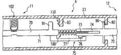
图9示出了根据本发明的器械10的又一实施例。该器械被设计为优选地用于单极技术的管轴器械并且可以例如与针电极32一起使用。器械10包括处于器械10的远端12的轴23以及处于近端11的布置于其上的夹紧装置51、52。用于支撑电极部件32和用于将电极部件32在轴的伸展方向E上(即线性地)从休息位置移动到工作位置的支撑元件(这里未示出)被布置于轴23内。支撑元件70的细节图在图10中作为细节图A示出。在休息位置,电极部件32撤回到轴23中并由此被容纳使之免于外部影响。为了治疗组织,电极部件32从轴23“移出”并因此可以被放置于组织上。支撑元件70的移动通过可沿着轴23移动的推元件60发生。柄形式的第一夹紧元件51被提拱用于保持器械10,而第二夹紧装置52连接到推元件60并且被设计用于放置手指,优选为拇指。推元件60因此可以通过拇指元件52a来移置以便由此移动支撑元件70。通过此手段,电极部件32可以极为容易地从休息位置移置到工作位置,其中推元件60与拇指元件52a一起经过第一行进区。Figure 9 shows a further embodiment of an
图10以细节图A示出了侧视图中的支撑元件70的一部分,如上面根据图9所述,其可以被布置于轴23中。根据图10,支撑元件70由远部分72和近部分71这两部分构成。电极部件32(未示出)被布置于支撑元件70的远部分72,以便通过推元件60与支撑元件70一起移动。支撑元件70在它的远部分72包括第一限制装置90,该装置从支撑元件70突起并且与第一轴突起92合作使得通过该合作可以设置电极部件32的工作位置。这意味着由于支撑元件70朝器械10的远端12的方向的移动,第一限制装置90与第一轴突起92接触并因此防止支撑元件70的进一步移动。限制装置90和轴突起92相对于彼此布置成使得一旦电极部件32到达它的工作位置就发生接触。FIG. 10 shows in detail A a part of a
支撑元件70被构造成使得借助于它的移动可以通过第二夹紧装置52起动开关装置110。如图10所示,支撑元件70的远部分72和近部分71通过可弹性变形元件100(在此情形下为螺旋弹簧)彼此链接。在此实施例中,杆元件73被布置于近部分71作为近部分71的延伸并且啮合于远部分72的相对凹陷72中。杆元件73承载可弹性变形元件100并且与之一起形成远和近部分72、71的连接。远部分72的凹陷74被配置成使得:甚至当处于远部分72的第一限制装置90已经与第一轴突起92接触并由此防止远部分72的进一步移动时,杆元件73并由此近部分71可以朝着远部分72进一步移动。然而,仅当足够大的力作用在可弹性变形元件100上使得它的变形(例如压缩)允许近部分71的进一步移动时,才有可能使杆元件73推入凹陷74。为了实现近部分71在伸展方向E上的进一步移动,用户仅须朝器械10的远端12的方向进一步移动推元件60,也就是说,继续进行将电极部件32从休息位置转移到工作位置的移动,其中推元件60与拇指元件52a一起经过第二行进区。由于第一限制装置90与第一轴突起92合作且同时推元件60被进一步移动从而超出第二行进区,力的施加得以实现。可弹性变形元件100用于提供远和近部分72、71之间的硬度,使得两个部分在电极部件32从休息位置转移到工作位置期间的移动可以同步发生,直到第一限制装置90与第一轴突起92合作为止。如果借助于推元件60来移动支撑元件70,则可弹性变形元件100由此沿着器械10的远端12的方向推远部分72。The
近部分71包括与第二轴突起93合作的第二限制装置91,其中第二限制装置91和第二轴突起93被布置成使得仅当第一限制装置90与第一轴突起92接触时才发生合作。在此示例实施例中,第二轴突起93包括可以通过第二限制装置91与第二轴突起93的合作来起动的开关装置110。这意味着,通过将处于支撑元件70的近部分71的杆元件73推入远部分72的凹陷74中并且通过可弹性变形元件100的压缩,可以起动开关装置110并激活电流馈送。The
为了将钳夹部件的电极部件30、31或电极部件32保持在它的工作位置,如果需要,可以提供闩锁装置102(其原则上具有与根据图7的闩锁装置相同的效果)。这里,通过弹簧与管轴耦合的制动钮(detent knob)啮合于支撑元件70上的环形槽中。在制动钮引导件中引导制动钮(闩锁装置的部件不更详细说明)。当在轴的伸展方向E上推动支撑元件70时,制动钮闩锁入环形槽中并将电极固定在它的对应位置。克服闩锁(增大作用在支撑元件上的力)实现如上所述开关装置110的起动。如果要中断电流供给,则可弹性变形元件100的恢复力将再次造成闩锁装置102的闩锁入。用户将可能不得不再次施加力以便将一个或多个电极部件转移到其最终休息位置。然而,可弹性变形元件100亦可以被配置成使得它的恢复效应至少额外地促进至休息位置的转移。开关装置110优选地配置为按钮110a,其中电流馈送的去激活可以通过“释放”(即,将第二限制装置91与开关装置110分离)来发生。这意味着用户在推元件上施加的力被减小或甚至被完全释放。如果可弹性变形元件100不配置成促进至休息位置的转移,则一个或多个电极部件保持在它们的工作位置。可能可以提供又一开关装置用于去激活电流馈送,或者该器械被配置成使得开关装置的重新起动导致去激活。In order to hold the
从根本上说,亦可以在支撑元件70的部分72、71之间仅布置有可弹性变形元件100而无杆元件73的情况下实现上述用于起动开关装置110的机构。这里,杆元件73用于在两个部分72、71之间稳定支撑元件70并且确保装置的可靠工作。此外,凹陷74的长度确定弹簧元件的可压缩程度。Fundamentally, the above-described mechanism for activating the
轴突起92、93可以可能与轴23整合地例如在轴23内布置,并且从轴23突起到轴23内部。由此,一旦限制装置90、91已到达了轴突起92、93,突起92、93就充当停止元件。同时,第二轴突起93承载开关装置110。突起92、93可以被提供为包括相应停止元件的单个元件或多个元件。突起92、93亦可以被提供为完整外围元件(例如盘元件)并由此形成轴23的一种变窄。这原则上同样适用于布置于支撑元件70的限制装置90、91。限制装置可以包括单个元件或多个这样的元件。The shaft protrusions 92 , 93 may be arranged possibly integrally with the
为了确保电极部件32“内移”至轴23中(即,电极部件32从工作位置转移回到休息位置),例如提供在内移期间将支撑元件70的两个部分71、72保持在一起的抑制装置75。在根据图10的示例实施例中,布置于支撑元件70的近部分71的杠杆77啮合于布置于远部分72的突起76后,使得在电极部件32内移时,近部分71携带着远部分72。在没有抑制装置75的情况下,可弹性变形元件100只要被紧固到两个部分71、72就将在返回电极部件32时拉伸,使得电极部件32从工作位置到休息位置的转移将可能以不协调的方式发生。In order to ensure that the electrode part 32 "moves in" into the shaft 23 (i.e. the electrode part 32 is transferred from the working position back to the rest position), for example means are provided which hold the two
图9中器械10的轴23上的椭圆形虚线表明:上述用于移动支撑元件70以便起动开关装置110的机构根据图10可以布置在那里、轴23内。图10示出了对应细节图A。The dotted oval line on the
支撑元件70通过推元件60的移动采用了支撑元件70与推元件60的连接60。推元件60可以例如通过轴23中的狭缝与支撑元件70连接并由此确保它的移动。The movement of the
图11示出了根据本发明的电外科器械10的一部分,具体为透视图中的器械10的近区11。这里亦提供用于起动支撑元件(未示出)的推元件60。椭圆形虚线同样指示根据图10的细节图A并且表明根据图10在轴23内提供用于移动支撑元件70以便起动开关装置110的机构。推元件60可在这里通过作为第二夹紧装置52的分支元件52b移动,分支元件52b在第一端可移动地布置(即铰接)于第一夹紧装置51(即轴23的柄),而在第二端通过可移动杠杆元件52c与推元件60连接。这意味着可移动杠杆元件52c与推元件60并与分支元件52b铰接。此外,环51b被安置于柄51a以便能够类似于一对剪刀地移动分支元件52b。一旦分支元件52b朝轴32的方向移动,推元件60就可以沿着轴移动并且在其中起动支撑元件70,如上面所述那样。移动经过分支元件52b即第二夹紧装置的第一行进区,电极部件行进到工作位置,而经过相邻的第二行进区导致开关装置110的起动和电流的激活。Fig. 11 shows a part of an
图12示出了根据本发明的电外科器械10的一部分,具体为透视图中的器械10的近区11。这里,椭圆形虚线同样指示根据图10的细节图A,也就是说,根据图10在轴23内提供用于移动支撑元件70以便起动开关装置110的机构。推元件60通过弹性元件52d(原则上是柄)与包括电流馈送装置40的腹板61链接,使得一旦弹性元件52d被压拢,推元件60就可以朝着腹板61移动。引导元件62a和62b稳定了支撑元件的推动。Fig. 12 shows a part of an
根据图12的柄被特别设计用于起动双极布置。例如,包括两个电极部件的钳夹部件(未示出)开启(图15),而推元件60和弹性元件52d位于休息位置。通过柄的起动,也就是说使推元件60朝着腹板移动,钳夹部件闭合(图16),其中该移动亦可以起动开关装置,如关于图11所述那样。如图15中所示,钳夹部件开启,也就是说电极部件30、31开启(休息位置)。柄的起动将电极部件30、31拉回到管轴23中,其中钳夹部件闭合,也就是说电极部件30、31朝着彼此移动。电极部件30、31的闭合如图16所示由两个弓形区33a和33b支撑,紧接在电极部件后布置弓形区33a和33b,使得它们与管轴内部的接触造成钳夹部件闭合。弓形区33a和33b通常通过电流馈送装置的弯曲来形成。由于通过电极的内移来达到工作位置,所以根据图10的布置优选地在这里反转,也就是说与例如图9中提供的方向相反的方向安装。由此,通过朝着腹板61进一步推进推元件60,亦可以根据本发明起动开关装置。The handle according to Fig. 12 is specially designed for starting bipolar arrangements. For example, the jaw member (not shown) comprising the two electrode members is opened ( FIG. 15 ), while the
优选地,钳夹部件即电极部件可以原则上仅在通过夹紧装置在电极部件上施加力期间保持闭合以抓持组织。这首先对迅速工作有利。弹性元件52d必须保持在它的压缩位置以便使电极部件30、31保持闭合。在“释放”时,钳夹部件开启并且电流馈送的去激活发生在推元件60的相关定位时。Preferably, the jaw part, ie the electrode part, can in principle remain closed for grasping tissue only during the exertion of force on the electrode part by the clamping device. This is advantageous above all for working quickly. The
在没有弹性元件(其不应与可弹性变形元件混淆)的夹紧装置的情形下,如果作用在夹紧装置上的力减小,则返回机构例如弹簧有可能迫使电极部件到它们的开启位置。此外,闩锁装置可以固定闭合的电极部件。这同样适用于其它实施例和单极布置。有效力施加或闩锁机构可以实现电流馈送和/或工作位置的维持。In the case of clamping means without elastic elements (which should not be confused with elastically deformable elements), it is possible for return mechanisms such as springs to force the electrode parts to their open position if the force acting on the clamping means decreases . Furthermore, the latching means can secure the closed pole parts. The same applies to other embodiments and single pole arrangements. Active force application or latching mechanisms can enable current feeding and/or maintenance of the working position.
本质上亦有可能将一个或多个电极部件(具有单极和双极布置)带到它们的工作位置,其中闩锁实现了工作位置的维持。尽管有闩锁机构,仍有可能如上所述起动开关装置。通过夹紧装置的“释放”或力减小于是可中断电流馈送,虽然工作位置仍将被维持。亦有可能设计该器械使得在去激活电流馈送时一个或多个电极部件转移到它们的休息位置或转移到开启位置。然而,器械可以不设计有任何闩锁机构,使得通过夹紧装置的有效起动来到达对应休息和工作位置。It is also inherently possible to bring one or more pole parts (with unipolar and bipolar arrangements) to their working position, wherein the latch enables maintenance of the working position. Despite the latch mechanism, it is still possible to actuate the switching device as described above. The current feed can then be interrupted by a "release" or force reduction of the clamping device, although the working position will still be maintained. It is also possible to design the device such that one or more electrode parts are shifted to their rest position or to an on position when the current feed is deactivated. However, the instrument may not be designed with any latching mechanism, so that the corresponding rest and working positions are reached by active actuation of the clamping device.
图13示出了根据本发明的电外科器械10的又一实施例。这里的椭圆形虚线同样指示根据图10的细节图A,也就是说,根据图10在轴23内提供用于移动支撑元件70以便起动开关装置110的机构。夹紧装置51、52朝着彼此的移动与注射器的起动类似地发生,其中环形第二夹紧装置52与第一夹紧装置51相反移动以便由此将电极部件32移动到工作位置并随后激活开关装置110。对于电极32,例如可以考虑用于单极凝固和/或切割的针电极32,所述电极借助于管轴23内部的支撑元件70来移动。夹紧装置的渐进相反移动实现如上所述开关装置的起动。Fig. 13 shows yet another embodiment of an
图14中所示电外科器械10基本上对应于图13中所示电外科器械10。简化表示图示出了侧视图中的器械10的近区11,虽然这里开关装置110被布置于器械10之外并且可以在夹紧装置已经聚拢后通过例如第一夹紧装置51的弯曲或折叠来起动。为此,可弹性变形元件100例如是弯曲元件,如上面具体所述(例如见图1),其被布置于夹紧装置51以便在与夹紧装置52一起移动的状态下使它朝开关装置110的方向进一步移动。由此可以起动开关装置。间隔元件80(停止件)在夹紧装置聚拢时限定第一行进区,而可弹性变形元件使得能够经过第二行进区。The
利用常常与腹腔镜检查器械一起提供的手枪型柄,例如可以朝着手枪握把移动可线性移动夹紧装置以起动支撑元件并且在其中移动经过第一行进区。耦合到可移动夹紧装置的例如可预张紧弹簧元件亦允许在此实施例中经过第二行进区以便起动开关装置。Using a pistol-type handle, which is often provided with laparoscopic instruments, the linearly movable gripping device can be moved, for example, towards the pistol grip to actuate the support element and move therein through the first zone of travel. For example a pretensionable spring element coupled to the movable clamping device also allows in this embodiment to pass through the second travel area in order to actuate the switching device.
这里应当指出,所有上述部分且特别是附图中所示细节,无论是单独的还是组合的,对于本发明都是必需的。对其进行修改是本领域技术人员的普通实践。It should be pointed out here that all the aforementioned parts and especially the details shown in the drawings are essential to the invention, both individually and in combination. Modifications thereto are common practice for those skilled in the art.
附图标记reference sign
10 电外科器械10 Electrosurgical Instruments
11 近区,近端11 near area, near end
12 远区,远端12 far zone, far end
20 分支20 branches
21 分支21 branches
22 联接点22 connection points
23 管轴,轴23 tube shaft, shaft
30 电极部件30 electrode parts
31 电极部件31 electrode parts
32 电极部件32 electrode parts
33a 弓形区33a Arcuate area
33b 弓形区33b Arcuate area
40 电流馈送装置40 current feeder
50 夹紧元件50 clamping elements
51 (第一)夹紧装置51 (first) clamping device
52 (第二)夹紧装置52 (second) clamping device
51a 柄51a handle
51b 环51b ring
52a 拇指元件52a Thumb element
52b 分支元件52b branch element
52c 杠杆元件52c lever element
52d 弹性元件52d elastic element
60 推元件60 push elements
61 腹板61 web
62a 引导元件62a Guide element
62b 引导元件62b Guide element
70 支撑元件70 Support elements
71 近部分71 close part
72 远部分72 far part
73 杆元件73 Rod elements
74 凹陷74 sunken
75 抑制装置75 suppression device
76 突起76 protrusions
77 杠杆77 leverage
80 间隔元件80 spacer elements
90 第一限制装置90 First restraint device
91 第二限制装置91 Second restraint device
92 第一轴突起92 first axis protrusion
93 第二轴突起93 second axis protrusion
100 可弹性变形元件100 Elastically deformable elements
101 可弹性变形元件101 Elastically deformable element
102 闩锁装置102 Latch device
110 开关装置110 switchgear
110a 按钮110a button
110b 簧片接触件110b Reed contact
111 遮盖元件111 cover element
112 开口区112 opening area
113 起动元件:起动栓,磁体元件113 Starting element: starting bolt, magnet element
A 根据图10的细节图A According to the detailed diagram in Figure 10
E 伸展方向E stretching direction
Claims (19)
Applications Claiming Priority (5)
| Application Number | Priority Date | Filing Date | Title |
|---|---|---|---|
| DE102005047405.5 | 2005-10-04 | ||
| DE102005047405 | 2005-10-04 | ||
| DE102006042985ADE102006042985A1 (en) | 2005-10-04 | 2006-09-13 | Electrosurgical instrument for coagulating tissue, has deformable unit arranged on branch or gripping device such that area of gripping device can be moved to actuate switching device when branches are closed and minimum distance is reached |
| DE102006042985.0 | 2006-09-13 | ||
| PCT/EP2006/009325WO2007039185A2 (en) | 2005-10-04 | 2006-09-26 | Electrosurgical instrument |
Related Child Applications (1)
| Application Number | Title | Priority Date | Filing Date |
|---|---|---|---|
| CN2010105225766ADivisionCN102048578B (en) | 2005-10-04 | 2006-09-26 | Electrosurgical instrument |
Publications (2)
| Publication Number | Publication Date |
|---|---|
| CN101277654A CN101277654A (en) | 2008-10-01 |
| CN101277654Btrue CN101277654B (en) | 2012-03-21 |
Family
ID=37896594
Family Applications (2)
| Application Number | Title | Priority Date | Filing Date |
|---|---|---|---|
| CN2010105225766AActiveCN102048578B (en) | 2005-10-04 | 2006-09-26 | Electrosurgical instrument |
| CN2006800367495AActiveCN101277654B (en) | 2005-10-04 | 2006-09-26 | Electrosurgical instrument |
Family Applications Before (1)
| Application Number | Title | Priority Date | Filing Date |
|---|---|---|---|
| CN2010105225766AActiveCN102048578B (en) | 2005-10-04 | 2006-09-26 | Electrosurgical instrument |
Country Status (6)
| Country | Link |
|---|---|
| US (1) | US8926610B2 (en) |
| EP (1) | EP1937174B1 (en) |
| JP (1) | JP5074406B2 (en) |
| CN (2) | CN102048578B (en) |
| DE (1) | DE102006042985A1 (en) |
| WO (1) | WO2007039185A2 (en) |
Families Citing this family (65)
| Publication number | Priority date | Publication date | Assignee | Title |
|---|---|---|---|---|
| GB0718268D0 (en) | 2007-09-19 | 2008-10-08 | Ayrshire And Arran Health Board | Retractor with integrated light source |
| DE102008032511B4 (en) | 2008-06-11 | 2012-08-30 | Erbe Elektromedizin Gmbh | Electrosurgical device with safety device |
| SG186344A1 (en)* | 2010-06-23 | 2013-01-30 | Univ Singapore | An articulating ablation and division device with blood flow sensing capability |
| US9005200B2 (en) | 2010-09-30 | 2015-04-14 | Covidien Lp | Vessel sealing instrument |
| AU2016201424B2 (en)* | 2010-09-30 | 2017-09-14 | Covidien Lp | Vessel sealing instrument |
| US9017372B2 (en)* | 2010-10-01 | 2015-04-28 | Covidien Lp | Blade deployment mechanisms for surgical forceps |
| AU2016231557B2 (en)* | 2010-10-04 | 2018-03-22 | Covidien Lp | Vessel sealing instrument |
| US9655672B2 (en) | 2010-10-04 | 2017-05-23 | Covidien Lp | Vessel sealing instrument |
| US9345534B2 (en)* | 2010-10-04 | 2016-05-24 | Covidien Lp | Vessel sealing instrument |
| US9039704B2 (en)* | 2011-06-22 | 2015-05-26 | Covidien Lp | Forceps |
| US20120330308A1 (en)* | 2011-06-22 | 2012-12-27 | Tyco Healthcare Group Lp | Forceps |
| DE102012100040A1 (en)* | 2012-01-04 | 2013-07-04 | Aesculap Ag | Electrosurgical instrument and jaw part for this |
| DE102012101257A1 (en) | 2012-02-16 | 2013-08-22 | Aesculap Ag | Electrosurgical instrument |
| AU2013230575B2 (en)* | 2012-03-08 | 2017-01-19 | Covidien Lp | Vessel sealing instrument |
| US8920461B2 (en) | 2012-05-01 | 2014-12-30 | Covidien Lp | Surgical forceps with bifurcated flanged jaw components |
| CN105007850B (en)* | 2012-05-02 | 2018-04-24 | 伊西康内外科公司 | For the electro-surgical device for cutting and solidifying |
| DE102012105263A1 (en) | 2012-06-18 | 2013-12-19 | Aesculap Ag | RF sealing instrument |
| DE102012210763A1 (en)* | 2012-06-25 | 2014-01-02 | Olympus Winter & Ibe Gmbh | gripping instrument |
| US9039691B2 (en) | 2012-06-29 | 2015-05-26 | Covidien Lp | Surgical forceps |
| US10070916B2 (en) | 2013-03-11 | 2018-09-11 | Covidien Lp | Surgical instrument with system and method for springing open jaw members |
| US9655673B2 (en) | 2013-03-11 | 2017-05-23 | Covidien Lp | Surgical instrument |
| US9456863B2 (en)* | 2013-03-11 | 2016-10-04 | Covidien Lp | Surgical instrument with switch activation control |
| US9622810B2 (en)* | 2013-05-10 | 2017-04-18 | Covidien Lp | Surgical forceps |
| AU2013375909B2 (en) | 2013-08-07 | 2015-07-30 | Covidien Lp | Bipolar surgical instrument |
| DE102013110595A1 (en)* | 2013-09-25 | 2015-04-09 | Aesculap Ag | HF surgical instrument |
| JP5855684B2 (en) | 2014-01-16 | 2016-02-09 | オリンパス株式会社 | Energy treatment tool |
| US10231776B2 (en) | 2014-01-29 | 2019-03-19 | Covidien Lp | Tissue sealing instrument with tissue-dissecting electrode |
| CN106535801B (en)* | 2014-04-02 | 2020-09-04 | 美国奥林匹斯外科技术吉鲁斯阿克米公司 | Surgical device with replaceable elements |
| US9433460B2 (en)* | 2014-05-30 | 2016-09-06 | Bipad, Llc | Electrosurgery actuator |
| US10660694B2 (en) | 2014-08-27 | 2020-05-26 | Covidien Lp | Vessel sealing instrument and switch assemblies thereof |
| US9877777B2 (en)* | 2014-09-17 | 2018-01-30 | Covidien Lp | Surgical instrument having a bipolar end effector assembly and a deployable monopolar assembly |
| US10136938B2 (en) | 2014-10-29 | 2018-11-27 | Ethicon Llc | Electrosurgical instrument with sensor |
| GB2532239A (en) | 2014-11-12 | 2016-05-18 | Clear Surgical Ltd | Retractor with improved light source, and light source for an improved retractor |
| KR102545505B1 (en)* | 2014-12-23 | 2023-06-20 | 어플라이드 메디컬 리소시스 코포레이션 | Bipolar Electrosurgical Sealers and Dividers |
| USD844139S1 (en) | 2015-07-17 | 2019-03-26 | Covidien Lp | Monopolar assembly of a multi-function surgical instrument |
| USD844138S1 (en) | 2015-07-17 | 2019-03-26 | Covidien Lp | Handle assembly of a multi-function surgical instrument |
| US9987078B2 (en) | 2015-07-22 | 2018-06-05 | Covidien Lp | Surgical forceps |
| US20170172614A1 (en)* | 2015-12-17 | 2017-06-22 | Ethicon Endo-Surgery, Llc | Surgical instrument with multi-functioning trigger |
| US10426543B2 (en) | 2016-01-23 | 2019-10-01 | Covidien Lp | Knife trigger for vessel sealer |
| CN106226116B (en)* | 2016-06-29 | 2019-04-19 | 靳琦 | For the utensil in biological organization sample slice preparation process |
| US10631887B2 (en) | 2016-08-15 | 2020-04-28 | Covidien Lp | Electrosurgical forceps for video assisted thoracoscopic surgery and other surgical procedures |
| US11602364B2 (en)* | 2016-11-16 | 2023-03-14 | Cilag Gmbh International | Surgical instrument with removable end effector components |
| US11172980B2 (en) | 2017-05-12 | 2021-11-16 | Covidien Lp | Electrosurgical forceps for grasping, treating, and/or dividing tissue |
| US10973567B2 (en) | 2017-05-12 | 2021-04-13 | Covidien Lp | Electrosurgical forceps for grasping, treating, and/or dividing tissue |
| USD854149S1 (en) | 2017-06-08 | 2019-07-16 | Covidien Lp | End effector for open vessel sealer |
| USD843574S1 (en) | 2017-06-08 | 2019-03-19 | Covidien Lp | Knife for open vessel sealer |
| USD854684S1 (en) | 2017-06-08 | 2019-07-23 | Covidien Lp | Open vessel sealer with mechanical cutter |
| US11896291B2 (en) | 2018-07-02 | 2024-02-13 | Covidien Lp | Electrically-insulative shafts, methods of manufacturing electrically-insulative shafts, and energy-based surgical instruments incorporating electrically-insulative shafts |
| CN109822626B (en)* | 2018-09-13 | 2021-01-26 | 阳江市港富实业有限公司 | Scissors |
| US11471211B2 (en) | 2018-10-12 | 2022-10-18 | Covidien Lp | Electrosurgical forceps |
| US11376062B2 (en) | 2018-10-12 | 2022-07-05 | Covidien Lp | Electrosurgical forceps |
| US11350982B2 (en) | 2018-12-05 | 2022-06-07 | Covidien Lp | Electrosurgical forceps |
| US11523861B2 (en) | 2019-03-22 | 2022-12-13 | Covidien Lp | Methods for manufacturing a jaw assembly for an electrosurgical forceps |
| US11712287B2 (en)* | 2019-04-18 | 2023-08-01 | Biosense Webster (Israel) Ltd. | Grasper tool with coagulation |
| EP3744278B1 (en)* | 2019-05-27 | 2024-08-14 | Erbe Elektromedizin GmbH | Electric surgical instrument and method for its manufacture |
| US11607267B2 (en)* | 2019-06-10 | 2023-03-21 | Covidien Lp | Electrosurgical forceps |
| US11298181B2 (en)* | 2019-06-27 | 2022-04-12 | Covidien Lp | Electrosurgical forceps |
| US12402934B2 (en) | 2019-09-15 | 2025-09-02 | Covidien Lp | Electrosurgical instrument for grasping, treating, and/or dividing tissue incorporating thermal management feature |
| US11622804B2 (en) | 2020-03-16 | 2023-04-11 | Covidien Lp | Forceps with linear trigger mechanism |
| US12295641B2 (en) | 2020-07-01 | 2025-05-13 | Covidien Lp | Electrosurgical forceps with swivel action nerve probe |
| US11660109B2 (en) | 2020-09-08 | 2023-05-30 | Covidien Lp | Cutting elements for surgical instruments such as for use in robotic surgical systems |
| US12343065B2 (en) | 2020-12-15 | 2025-07-01 | Covidien Lp | Energy-based surgical instrument for grasping, treating, and/or dividing tissue |
| US11806068B2 (en) | 2020-12-15 | 2023-11-07 | Covidien Lp | Energy-based surgical instrument for grasping, treating, and/or dividing tissue |
| US12059196B2 (en) | 2020-12-15 | 2024-08-13 | Covidien Lp | Energy-based surgical instrument for grasping, treating, and/or dividing tissue |
| DE102022116377B4 (en)* | 2022-06-30 | 2024-06-27 | Karl Storz Se & Co. Kg | FORCE LIMITED HANDLE, SURGICAL INSTRUMENT AND MODULAR INSTRUMENT SYSTEM |
Citations (5)
| Publication number | Priority date | Publication date | Assignee | Title |
|---|---|---|---|---|
| US3911241A (en)* | 1972-12-15 | 1975-10-07 | Neomed Inc | Switching device for electro-surgical instruments |
| US4274413A (en)* | 1978-10-06 | 1981-06-23 | Hahn Robert H | Depilatory tweezer |
| GB2156222A (en)* | 1984-03-17 | 1985-10-09 | Winter & Ibe Olympus | High frequency resection endoscope |
| DE4416499A1 (en)* | 1994-05-10 | 1995-11-30 | Buehler Instr Medizintechnik G | Bipolar coagulation tongs with automatic current switch |
| CN1102845C (en)* | 1994-12-21 | 2003-03-12 | 盖拉斯医疗有限公司 | Electrosurgical instrument |
Family Cites Families (14)
| Publication number | Priority date | Publication date | Assignee | Title |
|---|---|---|---|---|
| DE1901084U (en) | 1964-06-23 | 1964-09-24 | Delma Elektro Med App | ELECTRO-ARTERY CLAMP. |
| NL123580C (en) | 1968-01-11 | |||
| DE1919485A1 (en)* | 1969-04-17 | 1970-10-29 | Feinmechanik Ag F | Surgical cutting instrument |
| US4076028A (en)* | 1976-10-07 | 1978-02-28 | Concept Inc. | Forceps spacing device |
| US4311145A (en)* | 1979-07-16 | 1982-01-19 | Neomed, Inc. | Disposable electrosurgical instrument |
| CA1192465A (en)* | 1981-03-11 | 1985-08-27 | Edward A. Lottick | Removable switch electrocautery instruments |
| US4492231A (en)* | 1982-09-17 | 1985-01-08 | Auth David C | Non-sticking electrocautery system and forceps |
| DE3937700C2 (en)* | 1989-11-13 | 1998-02-19 | Sutter Hermann Select Med Tech | Bipolar coagulation forceps with switch |
| DE4113075C1 (en) | 1991-04-22 | 1992-07-02 | Kohler, Bruno | Surgical endoscope universal ring grip - has two cast arms with joint flaps formed by use of external casting cores |
| US6050996A (en)* | 1997-11-12 | 2000-04-18 | Sherwood Services Ag | Bipolar electrosurgical instrument with replaceable electrodes |
| JP4225624B2 (en)* | 1998-08-27 | 2009-02-18 | オリンパス株式会社 | High frequency treatment device |
| US6585735B1 (en)* | 1998-10-23 | 2003-07-01 | Sherwood Services Ag | Endoscopic bipolar electrosurgical forceps |
| US6110171A (en)* | 1999-03-09 | 2000-08-29 | Everest Medical Corporation | Electrosurgical cutting and coagulating instrument for open surgery |
| US7799026B2 (en)* | 2002-11-14 | 2010-09-21 | Covidien Ag | Compressible jaw configuration with bipolar RF output electrodes for soft tissue fusion |
- 2006
- 2006-09-13DEDE102006042985Apatent/DE102006042985A1/ennot_activeWithdrawn
- 2006-09-26EPEP06805862Apatent/EP1937174B1/enactiveActive
- 2006-09-26USUS12/089,369patent/US8926610B2/enactiveActive
- 2006-09-26JPJP2008533908Apatent/JP5074406B2/enactiveActive
- 2006-09-26CNCN2010105225766Apatent/CN102048578B/enactiveActive
- 2006-09-26WOPCT/EP2006/009325patent/WO2007039185A2/enactiveApplication Filing
- 2006-09-26CNCN2006800367495Apatent/CN101277654B/enactiveActive
Patent Citations (5)
| Publication number | Priority date | Publication date | Assignee | Title |
|---|---|---|---|---|
| US3911241A (en)* | 1972-12-15 | 1975-10-07 | Neomed Inc | Switching device for electro-surgical instruments |
| US4274413A (en)* | 1978-10-06 | 1981-06-23 | Hahn Robert H | Depilatory tweezer |
| GB2156222A (en)* | 1984-03-17 | 1985-10-09 | Winter & Ibe Olympus | High frequency resection endoscope |
| DE4416499A1 (en)* | 1994-05-10 | 1995-11-30 | Buehler Instr Medizintechnik G | Bipolar coagulation tongs with automatic current switch |
| CN1102845C (en)* | 1994-12-21 | 2003-03-12 | 盖拉斯医疗有限公司 | Electrosurgical instrument |
Also Published As
| Publication number | Publication date |
|---|---|
| EP1937174B1 (en) | 2012-09-19 |
| US20080215048A1 (en) | 2008-09-04 |
| US8926610B2 (en) | 2015-01-06 |
| CN102048578B (en) | 2012-08-29 |
| JP5074406B2 (en) | 2012-11-14 |
| WO2007039185A2 (en) | 2007-04-12 |
| EP1937174A2 (en) | 2008-07-02 |
| DE102006042985A1 (en) | 2007-04-19 |
| JP2009509706A (en) | 2009-03-12 |
| CN101277654A (en) | 2008-10-01 |
| WO2007039185A3 (en) | 2007-10-11 |
| CN102048578A (en) | 2011-05-11 |
Similar Documents
| Publication | Publication Date | Title |
|---|---|---|
| CN101277654B (en) | Electrosurgical instrument | |
| US11350983B2 (en) | Tissue sealing instrument with tissue-dissecting electrode | |
| US10117709B2 (en) | Modular surgical instruments with contained electrical or mechanical systems | |
| EP3030176B1 (en) | Bipolar surgical instrument with tissue stop | |
| US5433725A (en) | Hand-held surgical device and tools for use therewith, assembly and method | |
| US11382686B2 (en) | Surgical forceps | |
| US20220257310A1 (en) | Monopolar and bipolar functionality | |
| EP3030179B1 (en) | Bipolar surgical instrument | |
| US20180271587A1 (en) | Energy treatment instrument | |
| US10426543B2 (en) | Knife trigger for vessel sealer | |
| US20200222109A1 (en) | Electrosurgical instruments | |
| US10660694B2 (en) | Vessel sealing instrument and switch assemblies thereof | |
| WO2014108668A1 (en) | Surgical tool |
Legal Events
| Date | Code | Title | Description |
|---|---|---|---|
| C06 | Publication | ||
| PB01 | Publication | ||
| C10 | Entry into substantive examination | ||
| SE01 | Entry into force of request for substantive examination | ||
| C14 | Grant of patent or utility model | ||
| GR01 | Patent grant |