CN101273601A - Method and apparatus for carrier allocation and management in a multi-carrier communication system - Google Patents
Method and apparatus for carrier allocation and management in a multi-carrier communication systemDownload PDFInfo
- Publication number
- CN101273601A CN101273601ACNA2006800354048ACN200680035404ACN101273601ACN 101273601 ACN101273601 ACN 101273601ACN A2006800354048 ACNA2006800354048 ACN A2006800354048ACN 200680035404 ACN200680035404 ACN 200680035404ACN 101273601 ACN101273601 ACN 101273601A
- Authority
- CN
- China
- Prior art keywords
- reverse link
- carriers
- terminal
- link carriers
- accesses terminal
- Prior art date
- Legal status (The legal status is an assumption and is not a legal conclusion. Google has not performed a legal analysis and makes no representation as to the accuracy of the status listed.)
- Pending
Links
Images


Classifications
- H—ELECTRICITY
- H04—ELECTRIC COMMUNICATION TECHNIQUE
- H04L—TRANSMISSION OF DIGITAL INFORMATION, e.g. TELEGRAPHIC COMMUNICATION
- H04L5/00—Arrangements affording multiple use of the transmission path
- H04L5/0001—Arrangements for dividing the transmission path
- H04L5/0003—Two-dimensional division
- H04L5/0005—Time-frequency
- H04L5/0007—Time-frequency the frequencies being orthogonal, e.g. OFDM(A) or DMT
- H—ELECTRICITY
- H04—ELECTRIC COMMUNICATION TECHNIQUE
- H04L—TRANSMISSION OF DIGITAL INFORMATION, e.g. TELEGRAPHIC COMMUNICATION
- H04L5/00—Arrangements affording multiple use of the transmission path
- H04L5/003—Arrangements for allocating sub-channels of the transmission path
- H04L5/0044—Allocation of payload; Allocation of data channels, e.g. PDSCH or PUSCH
- H04L5/0046—Determination of the number of bits transmitted on different sub-channels
- H—ELECTRICITY
- H04—ELECTRIC COMMUNICATION TECHNIQUE
- H04L—TRANSMISSION OF DIGITAL INFORMATION, e.g. TELEGRAPHIC COMMUNICATION
- H04L5/00—Arrangements affording multiple use of the transmission path
- H04L5/003—Arrangements for allocating sub-channels of the transmission path
- H04L5/0058—Allocation criteria
- H04L5/006—Quality of the received signal, e.g. BER, SNR, water filling
- H—ELECTRICITY
- H04—ELECTRIC COMMUNICATION TECHNIQUE
- H04L—TRANSMISSION OF DIGITAL INFORMATION, e.g. TELEGRAPHIC COMMUNICATION
- H04L5/00—Arrangements affording multiple use of the transmission path
- H04L5/0091—Signalling for the administration of the divided path, e.g. signalling of configuration information
- H04L5/0094—Indication of how sub-channels of the path are allocated
- H—ELECTRICITY
- H04—ELECTRIC COMMUNICATION TECHNIQUE
- H04W—WIRELESS COMMUNICATION NETWORKS
- H04W28/00—Network traffic management; Network resource management
- H04W28/16—Central resource management; Negotiation of resources or communication parameters, e.g. negotiating bandwidth or QoS [Quality of Service]
- H04W28/18—Negotiating wireless communication parameters
- H—ELECTRICITY
- H04—ELECTRIC COMMUNICATION TECHNIQUE
- H04W—WIRELESS COMMUNICATION NETWORKS
- H04W52/00—Power management, e.g. Transmission Power Control [TPC] or power classes
- H04W52/04—Transmission power control [TPC]
- H04W52/30—Transmission power control [TPC] using constraints in the total amount of available transmission power
- H04W52/34—TPC management, i.e. sharing limited amount of power among users or channels or data types, e.g. cell loading
- H—ELECTRICITY
- H04—ELECTRIC COMMUNICATION TECHNIQUE
- H04L—TRANSMISSION OF DIGITAL INFORMATION, e.g. TELEGRAPHIC COMMUNICATION
- H04L5/00—Arrangements affording multiple use of the transmission path
- H04L5/0001—Arrangements for dividing the transmission path
- H04L5/0003—Two-dimensional division
- H04L5/0005—Time-frequency
Landscapes
- Engineering & Computer Science (AREA)
- Signal Processing (AREA)
- Computer Networks & Wireless Communication (AREA)
- Quality & Reliability (AREA)
- Mobile Radio Communication Systems (AREA)
Abstract
Translated fromChinese
Description
Translated fromChinese在35 U.S.C.§下的优先权要求Priority claims under 35 U.S.C.§
本专利申请要求2005年9月27日提交的题为“Location-based CarrierAllocation in a Multi-carrier Wireless Communication System(多载波无线通信系统中基于位置的载波分配)”的临时专利申请No.60/721,343的优先权,其已被转让给本申请的受让人并因而被明确援引纳入于此。This patent application claims Provisional Patent Application No. 60/721,343, filed September 27, 2005, entitled "Location-based Carrier Allocation in a Multi-carrier Wireless Communication System" , which has been assigned to the assignee of the present application and is hereby expressly incorporated by reference.
相关申请的交叉引用Cross References to Related Applications
本专利申请涉及2006年3月7日提交的题为“Multi-carrier,Multi-flow,ReverseLink Medium Access Control For a Communication System(通信系统用多载波多流反向链路媒体接入控制)”的美国专利申请No.11/371,274,其在35 U.S.C.§119下要求2005年3月8日提交的题为“Multi-carrier,Multi-flow Reverse Link MediumAccess Control For a Communication System(通信系统用多载波多流反向链路媒体接入控制)”的临时专利申请No.60/659,989的优先权。This patent application relates to the patent titled "Multi-carrier, Multi-flow, ReverseLink Medium Access Control For a Communication System (multi-carrier multi-flow reverse link media access control for communication system)" submitted on March 7, 2006 U.S. Patent Application No. 11/371,274, which claims under 35 U.S.C. §119 entitled "Multi-carrier, Multi-flow Reverse Link Medium Access Control For a Communication System" filed March 8, 2005 Priority to Provisional Patent Application No. 60/659,989 for Stream Reverse Link Media Access Control).
背景background
领域field
本公开一般涉及无线通信系统。更具体地,本文中公开的实施例涉及多载波通信系统中的载波分配和管理。The present disclosure generally relates to wireless communication systems. More specifically, embodiments disclosed herein relate to carrier allocation and management in multi-carrier communication systems.
背景background
通信系统已被发展成允许从始发站向物理上相异的目的站传送信息信号。在一通信信道上传送来自始发站的信息信号时,该信息信号首先被转换成适合在该通信信道上高效率传输的形式。该信息信号的转换即调制涉及根据该信息信号变化载波的参数以使得结果所得的已调制载波的频谱被限制在该通信信道的带宽内。在目的站处,从在该通信信道上接收到的已调制载波复制出原始信息信号。这样的一种复制一般是通过使用始发站所采用的调制过程的逆转来达成的。Communication systems have been developed to allow information signals to be transmitted from an originating station to a physically distinct destination station. When transmitting an information signal from an originating station over a communication channel, the information signal is first converted into a form suitable for efficient transmission over the communication channel. Conversion or modulation of the information signal involves varying parameters of the carrier in accordance with the information signal such that the spectrum of the resulting modulated carrier is limited within the bandwidth of the communication channel. At the destination station, the original information signal is copied from the modulated carrier wave received on the communication channel. Such a duplication is generally achieved by using an inversion of the modulation process employed by the originating station.
调制还便于实现数个信号在一公共通信信道上的多址——例如同时传送和/或接收。例如,多址通信系统可包括请求间歇服务而不是连续接入此公共通信信道的多个远程订户单元(或接入终端)。多址技术可包括码分多址(CDMA)、时分多址(TDMA)、频分多址(FDMA)、正交频分多址(OFDMA)、以及其他多址技术。Modulation also facilitates multiple access - eg simultaneous transmission and/or reception - of several signals on a common communication channel. For example, a multiple-access communication system may include multiple remote subscriber units (or access terminals) that request intermittent service rather than continuous access to the common communication channel. Multiple-access techniques may include Code Division Multiple Access (CDMA), Time Division Multiple Access (TDMA), Frequency Division Multiple Access (FDMA), Orthogonal Frequency Division Multiple Access (OFDMA), and other multiple access techniques.
多址通信系统可以是无线的和/或有线的,并且可以承载语音、数据等。通信系统可被设计成实现一种或多种标准。Multiple-access communication systems can be wireless and/or wireline and can carry voice, data, and so on. Communication systems may be designed to implement one or more standards.
随着对多媒体业务和高速率数据的需求急速增长,在无线通信系统中已经提出了多载波调制。存在着要提供高效率且强健的多载波通信系统的挑战。With the rapid increase in the demand for multimedia services and high-rate data, multi-carrier modulation has been proposed in wireless communication systems. There is a challenge to provide an efficient and robust multi-carrier communication system.
附图简要说明Brief description of the drawings
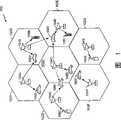
图1图解了支持数个用户并能够实现本文中讨论的诸实施例的至少一些方面的通信系统的一个示例;Figure 1 illustrates one example of a communication system that supports a number of users and is capable of implementing at least some aspects of the embodiments discussed herein;
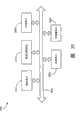
图2是图解了高数据率通信系统中的接入网络和接入终端的框图;Figure 2 is a block diagram illustrating an access network and access terminals in a high data rate communication system;
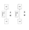
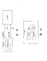
图3是图解了接入终端上层的堆栈的框图;Figure 3 is a block diagram illustrating a stack at the upper layers of an access terminal;
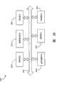
图4是图解了接入终端上的高层、媒体接入控制层、和物理层之间的示例性交互的框图;4 is a block diagram illustrating exemplary interactions between upper layers on an access terminal, a media access control layer, and a physical layer;
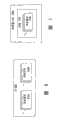
图5A是图解了正向该接入网络传送高容量分组的框图;Figure 5A is a block diagram illustrating the forwarding of high capacity packets to the access network;
图5B是图解了正向该接入网络传送低延迟(latency)分组的框图;Figure 5B is a block diagram illustrating forwarding low-latency (latency) packets to the access network;
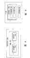
图6是图解了接入网络上可能存在的不同类型的流的框图;Figure 6 is a block diagram illustrating different types of flows that may exist on an access network;
图7是图解了高容量分组的示例性流集的框图;Figure 7 is a block diagram illustrating an exemplary flow set of high capacity packets;
图8是图解了低延迟分组的示例性流集的框图;FIG. 8 is a block diagram illustrating an exemplary flow set of low-latency packets;
图9是图解了可在接入终端处维护以确定是否有高容量流被包括在低延迟分组的流集中的信息的框图;9 is a block diagram illustrating information that may be maintained at an access terminal to determine whether a high capacity flow is included in a flow set of low delay packets;
图10是图解了接入网络和一个扇区内的多个接入终端的框图;10 is a block diagram illustrating an access network and multiple access terminals within a sector;
图11图解了可用来确定接入终端的总共可用功率的示例性机制;11 illustrates an example mechanism that may be used to determine total available power for an access terminal;
图12是图解了一扇区内中至少有一些接入终端包括多个流的一个实施例的框图;Figure 12 is a block diagram illustrating an embodiment in which at least some access terminals within a sector include multiple flows;
图13是图解了接入终端可藉以获得对该接入终端上诸流的当前功率分配的一种方式的框图;13 is a block diagram illustrating one manner in which an access terminal may obtain current power allocations for flows on the access terminal;
图14是图解了正从接入网络向一扇区内各接入终端传送反向活跃性比特的框图;14 is a block diagram illustrating reverse activity bits being transmitted from an access network to access terminals within a sector;
图15是图解了可在接入终端处维护以确定对该接入终端上的一个或多个流的当前功率分配的信息的框图;15 is a block diagram illustrating information that may be maintained at an access terminal to determine current power allocations for one or more streams on the access terminal;
图16是图解了接入终端中可用来确定反向活跃性比特的估计和扇区的当前负载程度的估计的示例性功能组件的功能框图;16 is a functional block diagram illustrating example functional components in an access terminal that may be used to determine an estimate of reverse activity bits and an estimate of a sector's current load level;
图17是图解了一种用于确定对接入终端上的流的当前功率分配的示例性方法的流程图;17 is a flow diagram illustrating an example method for determining current power allocations to streams on an access terminal;
图18是图解了接入终端向接入网络上的调度器发送请求消息的框图;18 is a block diagram illustrating an access terminal sending a request message to a scheduler on an access network;
图19是图解了可在接入终端处维护以供接入终端确定何时向接入网络发送请求消息的信息的框图。19 is a block diagram illustrating information that may be maintained at an access terminal for the access terminal to determine when to send a request message to the access network.
图20是图解了在接入网络上运行的调度器与扇区内各接入终端之间的一种示例性交互的框图。20 is a block diagram illustrating an example interaction between a scheduler operating on an access network and access terminals within a sector.
图21是图解了在接入网络上运行的调度器与接入终端之间的另一种示例性交互的框图。21 is a block diagram illustrating another example interaction between a scheduler operating on an access network and an access terminal.
图22是图解了从接入网络上的调度器向接入终端传送的准予消息的另一个实施例的框图;Figure 22 is a block diagram illustrating another embodiment of a grant message transmitted from a scheduler on an access network to an access terminal;
图23是图解了可存储在接入终端处的功率概况的框图;23 is a block diagram illustrating a power profile that may be stored at an access terminal;
图24是图解了可存储在接入终端处的多个传输条件的框图;24 is a block diagram illustrating a number of transmission conditions that may be stored at an access terminal;
图25是图解了一种可由接入终端执行以确定分组的有效载荷大小和功率能级的示例性方法的流程图;25 is a flow diagram illustrating an example method that may be performed by an access terminal to determine the payload size and power level of a packet;
图26是图解了接入终端的一个实施例的功能框图;Figure 26 is a functional block diagram illustrating one embodiment of an access terminal;
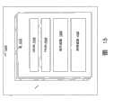
图27图解了在接入终端处通过为每一MAC层流分别使用两组令牌桶来将流接入控制与流数据管制去耦的一个示例;Figure 27 illustrates an example of decoupling flow access control from flow data policing at the access terminal by using two separate sets of token buckets for each MAC layer flow;
图28是图解了当在RTC MAC层中管制流数据时执行的步骤的流程图;Figure 28 is a flowchart illustrating the steps performed when policing flow data in the RTC MAC layer;
图29是图解了接入终端向接入网络上的调度器发送载波请求消息并接收载波准予消息的框图;29 is a block diagram illustrating an access terminal sending a carrier request message and receiving a carrier grant message to a scheduler on an access network;
图30示出了图解多载波通信中载波分配和管理的一个示例的呼叫流向图;Figure 30 shows a call flow diagram illustrating an example of carrier allocation and management in multi-carrier communication;
图31示出了图解多载波通信中载波分配和管理的一个示例的呼叫流向图;Figure 31 shows a call flow diagram illustrating an example of carrier allocation and management in multi-carrier communication;
图32示出了图解多载波通信中载波分配和管理的一个示例的呼叫流向图;Figure 32 shows a call flow diagram illustrating an example of carrier allocation and management in multi-carrier communication;
图33示出了图解多载波通信中载波分配和管理的一个示例的呼叫流向图;Figure 33 shows a call flow diagram illustrating an example of carrier allocation and management in multi-carrier communication;
图34示出了图解多载波通信中载波分配和管理的一个示例的呼叫流向图;Figure 34 shows a call flow diagram illustrating an example of carrier allocation and management in multi-carrier communication;
图35图解了可用于实现一些公开的实施例的框图;以及Figure 35 illustrates a block diagram that may be used to implement some disclosed embodiments; and
图36图解了可用于实现一些公开的实施例的框图。Figure 36 illustrates a block diagram that may be used to implement some disclosed embodiments.
具体说明Specific instructions
本文中公开的实施例涉及用于在通信系统中进行载波分配和管理的方法和装置。Embodiments disclosed herein relate to methods and apparatus for carrier allocation and management in a communication system.
本文中公开的接入点(AP)可包括和/或实现基站收发机系统(BTS)、接入网络收发机(ANT)、调制解调器群收发机(MPT)、或B节点(例如,在W-CDMA类型的系统中)等的功能。蜂窝小区可指由一AP服务的覆盖区域。蜂窝小区可进一步包括一个或多个扇区。为简单和清楚起见,本文中可使用术语“扇区”来表示由一AP服务的蜂窝小区、或蜂窝小区的一个区段。此外,接入网络控制器(ANC)可指通信系统中配置成与核心网络(例如,分组数据网络)接口并在接入终端(AT)与该核心网络之间路由数据分组、执行各种无线电接入和链路维护功能(诸如软换手)、控制无线电发射机和接收机等的部分。ANC可包括和/或实现基站控制器(BSC)的功能,诸如在第2代、第3代、或第4代无线网络中可见到的那样。NC与一个或多个AP可构成接入网络(AN)的一部分。An Access Point (AP) disclosed herein may include and/or implement a Base Transceiver System (BTS), an Access Network Transceiver (ANT), a Modem Pool Transceiver (MPT), or a Node B (e.g., in W- CDMA type system) and so on. A cell may refer to a coverage area served by an AP. A cell may further include one or more sectors. For simplicity and clarity, the term "sector" may be used herein to refer to a cell, or a section of a cell, served by an AP. Additionally, an access network controller (ANC) may refer to a communication system configured to interface with a core network (e.g., a packet data network) and route data packets between an access terminal (AT) and the core network, perform various radio Part of the access and link maintenance functions (such as soft handover), control of radio transmitters and receivers, etc. The ANC may include and/or implement the functionality of a base station controller (BSC), such as may be found in 2nd, 3rd, or 4th generation wireless networks. The NC and one or more APs may form part of an Access Network (AN).
本文中描述的接入终端(AP)可指各种类型的设备,包括(但不限于)无线电话、蜂窝电话、膝上型计算机、多媒体无线设备、无线通信个人计算机(PC)卡、个人数字助理(PDA)、外置或内置调制解调器等。AT可以是通过无线信道和/或通过有线信道(例如,借助于光纤或同轴电缆)通信的任何数据设备。AT可具有各种名称,诸如接入单元、接入节点、订户单元、移动站、移动设备、移动单元、移动电话、移动台、远程站、远程终端、远程单元、用户设备、用户装备、手持式设备等等。不同的AT可被纳入到系统中。AT可以是移动的或静止的,并可散布遍及通信系统各处。在给定时刻,AT可在前向链路和/或反向链路上与一个或多个AP通信。前向链路(或下行链路)是指从AP向AT的传输。反向链路(或上行链路)是指从AT向AP的传输。An access terminal (AP) as described herein may refer to various types of devices including, but not limited to, wireless telephones, cellular telephones, laptop computers, multimedia wireless devices, wireless communication personal computer (PC) cards, personal digital Assistant (PDA), external or internal modem, etc. An AT may be any data device that communicates through a wireless channel and/or through a wired channel (eg, by means of fiber optic or coaxial cables). ATs may have various names such as access unit, access node, subscriber unit, mobile station, mobile device, mobile unit, mobile phone, mobile station, remote station, remote terminal, remote unit, user equipment, user equipment, handheld equipment, etc. Different ATs can be incorporated into the system. ATs can be mobile or stationary and can be dispersed throughout the communication system. At a given moment, an AT may communicate with one or more APs on the forward and/or reverse links. The forward link (or downlink) refers to transmissions from the AP to the AT. The reverse link (or uplink) refers to the transmission from the AT to the AP.
图1图解了配置成支持数个用户的、在其中如在下面进一步描述地可实现各个公开的实施例和方面的无线通信系统100。举例而言,系统100为包括蜂窝小区120A-102G在内的数个蜂窝小区102提供通信,其中每一蜂窝小区由一相应的AP 104(诸如AP 104A-104G)服务。每一蜂窝小区可被进一步分成一个或多个扇区。包括AT 106A-106K在内的各个AT 106分布遍及该系统各处。在给定时刻,取决于例如AT是否活跃以及其是否处于软换手中,每一AT 106可在前向链路和/或反向链路上与一个或多个AP 104通信。1 illustrates a
在图1中举例而言,带箭头的实线可指示从AP向AT的信息(例如,数据)传输。带箭头的虚线可指示AT正在接收来自AP的导频以及其他信令/参考信号(但非数据传输)。为清楚和简单,在图1中没有显性地示出反向链路通信。In FIG. 1, for example, a solid line with an arrow may indicate information (eg, data) transmission from an AP to an AT. A dashed line with an arrow may indicate that the AT is receiving pilot and other signaling/reference signals (but not data transmissions) from the AP. For clarity and simplicity, reverse link communication is not shown explicitly in FIG. 1 .
AP 104可各自装备有一个或多个接收天线、以及一个或多个发射天线。AP104处可以有发射天线和接收天线的任意组合。类似地,每一AT 106可装备有一个或多个接收及发射天线、或其组合。APs 104 may each be equipped with one or more receive antennas, and one or more transmit antennas. There may be any combination of transmit and receive antennas at the AP 104. Similarly, each AT 106 may be equipped with one or more receive and transmit antennas, or a combination thereof.
系统100可被配置成支持一种或多种标准,例如IS-95、cdma2000、IS-856、W-CDMA、TD-SCDMA、IEEE 802.11a、802.11g、802.11n、802.16e、802.20、其他标准、或其组合。在一个实施例中,例如,系统100可以是高速率分组数据(HRPD)系统,诸如在“cdma2000高速率分组数据空中接口规范”3GPP2 C.S0024-B,版本1,2006年5月中规定的系统(也称作“1xEV-DO”或“IS-856”类型系统)。此外,可使用各种算法及方法在系统100中调度传输和促进通信。在1xEV-DO系统中使用的这些算法及方法的详情在下面进一步描述。
图2图解了通信系统中的AN 204和AT 206的一个实施例。举例而言,AT 206可正处于与AN 204的无线通信中,例如在包括反向话务信道208的反向链路上无线通信。反向话务信道208是反向信道中承载从AT 206去往AN 204的信息的部分。除了反向话务信道208以外,反向信道还可包括其他信道。此外,AT 206可处于在包括多个信道(例如,导频、话务、及其他信道)的前向链路上与AN 204的无线通信中,这在图2中没有显性地示出。FIG. 2 illustrates one embodiment of an
由AT 206执行的功能集可被组织成层的堆栈。图3图解了AT 306上的层的堆栈。在这些层当中有媒体接入控制(MAC)层308。高层310位于MAC 308之上。MAC层308向高层310提供某些服务,包括涉及反向话务信道208的操作的服务。MAC层308包括反向话务信道(RTC)MAC协议314的实现。RTC MAC协议314提供由AT 306循其以传送/由AN 204循其以接收反向话务信道208的过程。The set of functions performed by the
物理层312位于MAC层308之下。MAC层308向物理层312请求某些服务。这些服务涉及向AN 204进行分组的物理传输。Physical layer 312 is located below MAC layer 308 . The MAC layer 308 requests certain services from the physical layer 312 . These services involve the physical transmission of packets to the
图4图解了AT 406上的高层410、MAC层408、和物理层412之间的示例性交互。如图所示,MAC层408从高层410接收一个或多个流416。流416是来自用户源的具有预定传输要求(例如,与特定应用相关联)的一股数据。例如,流416对应于一具体的应用,诸如IP电话(VoIP)、视频电话、文件传输协议(FTP)、游戏等。FIG. 4 illustrates exemplary interactions between the
来自AT 406上诸流416的数据以分组形式传送给AN 204。根据RTC MAC协议414,MAC层确定每一分组的流集418。有时AT 406上的多个流416有要同时传送的数据。一个分组可包括来自一个以上的流416的数据。但是,有时AT 406上有一个或多个流416有数据要传送,但这些数据并非被包括在一个分组中。分组的流集418指示AT 406上要被包括在该分组中的那些流416。用于确定分组的流集418的示例性方法将在下面描述。Data from
MAC层408还确定每一分组的有效载荷大小420。分组的有效载荷大小420指示有多少来自流集418的数据被包括在该分组中。The
MAC层408还确定分组的功率能级422。在一些实施例中,分组的功率能级422是相对于反向导频信道的功率能级来确定的。The
对于向AN 204传送的每一分组,MAC层408向物理层412通报要被包括在该分组中的流集418、该分组的有效载荷大小420、以及该分组的功率能级422。物理层412然后根据MAC层408所提供的信息来向AN 204实行该分组的传输。For each packet transmitted to AN 204,
图5A和5B图解了正从AT 506向AN 504传送分组524。分组524可在数种可能的传输模式(TM)下传送。例如,在一些实施例中有两种可能的传输模式,即高容量传输模式和低延迟传输模式。图5A图解了正在向AN 504传送高容量分组524a(即,在高容量模式下传送的分组524a)。图5B图解了正在向AN 504传送低延迟分组524b(即,在低延迟模式下传送的分组524b)。5A and 5B illustrate that the packet 524 is being transmitted from the
来自延迟敏感性流(LoLat流)的数据可使用低延迟(LoLat)传输模式来发送。来自延迟耐受性流(HiCap流)的数据可使用高容量(HiCap)传输模式来发送。低延迟分组524b是在高于分组大小相同的高容量分组524a的功率能级422下传送的。因此,低延迟分组524b很可能比高容量分组524a更快地到达AN 504处。但是,低延迟分组分组524b相比高容量分组524a造成系统100上更大的负载。Data from delay-sensitive streams (LoLat streams) may be sent using a low-latency (LoLat) transport mode. Data from a delay tolerant stream (HiCap stream) may be sent using a high capacity (HiCap) transfer mode.
图6图解了AT 606上可能存在的不同类型的流616。在一些实施例中,AT 606上的每一个流616与一特定传输模式相关联。在可能的传输模式是高容量传输模式和低延迟传输模式的场合,AT 606可包括一个或多个高容量流616a和/或一个或多个低延迟流616b。高容量流616a优选以高容量分组524a的形式来传送。低延迟流616b优选以低延迟分组524b的形式来传送。Figure 6 illustrates the different types of streams 616 that may exist on the
图7图解了高容量分组724a的流集718的一个示例。在一些实施例中,仅当有数据要传送的所有流716皆为高容量流716a时才在高容量模式下传送分组724a。相应地,在这样的实施例中,高容量分组724a中的流集718仅包括高容量流716a。替换地,低延迟流616b可被包括在高容量分组724a中,这由AT 606自行斟酌。低延迟流616b达不到足够的吞吐是这样做的一个示例性原因。例如,可能检测到低延迟流616b的队列正在逐渐堆积。此流可通过代之以使用高容量模式来改善其吞吐,其代价是延迟延长。Figure 7 illustrates one example of a flow set 718 of high capacity packets 724a. In some embodiments, packet 724a is transmitted in high capacity mode only if all flows 716 that have data to transmit are high capacity flows 716a. Accordingly, in such an embodiment, flow set 718 in high capacity packet 724a includes only high capacity flow 716a. Alternatively, the low-latency stream 616b may be included in the high-capacity packet 724a, at the discretion of the
图8图解了低延迟分组824b的示例性流集818。在一些实施例中,如果至少有一个低延迟流816b有数据要传送,则分组824b在低延迟模式下被传送。低延迟分组824b中的流集818包括有数据要传送的每一低延迟流816b。有数据要传送的诸高容量流816a中有一个或多个也可被包括在流集818中。但是,有数据要传送的诸高容量流816a中有一个或多个可不被包括在流集818中。FIG. 8 illustrates an exemplary flow set 818 of low-latency packets 824b. In some embodiments, the packet 824b is transmitted in low-latency mode if at least one low-
将并发的低延迟流和高容量流归并在每一反向链路载波中的物理层分组中Combines concurrent low-latency and high-capacity flows in physical layer packets on each reverse link carrier
当AT 906包含不同终端目标的多个流时发生归并。因为每一物理分组可具有一个终端目标,因此可使用规则来确定何时诸流可被归并到同一分组中。用于将并发的低延迟流和高容量流归并到一分组中的规则依赖于流优先级和扇区负载。图9图解了可在AT 906处维护以确定是否有高容量流916a被包括在低延迟分组824b的流集818中的信息。AT 906上的每一高容量流916a有一定量的可供传输的数据926。还可为AT 906上的每一高容量流916a定义一归并阈值928。另外,可整体上为AT 906定义一归并阈值930。最终,当扇区的负载程度的估计低于阈值时可发生高容量流的归并。(如何确定扇区的负载程度的估计将在下面讨论。)亦即,当扇区的负载足够轻时,归并的效率损失就不再重要并且进取式使用被允许。Merging occurs when the
在一些实施例中,如果下面两个条件中有任意一个满足,则高容量流916a被包括在低延迟分组524b中。第一个条件是AT 906上所有高容量流916a的可传送数据926之和超过为该AT 906定义的归并阈值930。第二个条件是高容量流916a的可传送数据926超过为该高容量流916a定义的归并阈值928。In some embodiments, the high capacity flow 916a is included in the
第一个条件涉及从低延迟分组824b向高容量分组724a的功率转移。如果不将高容量流916a包括在低延迟分组824b中,则只要有来自至少一个低延迟流816b的数据可供传送,来自高容量流916a的数据就逐渐堆积。如果允许过多来自高容量流916a的数据积聚,则下一次传送高容量分组724a时,就可能会有从上一低延迟分组824b到该高容量分组724a的急剧到不可接受的功率转移。因此,根据此第一个条件,一旦来自AT 906上的高容量流916a的可传送数据926的量超过某一值(由归并阈值930定义),就允许将来自高容量流916a的数据“归并”到低延迟分组824b中。The first condition involves power transfer from low-latency packets 824b to high-capacity packets 724a. If the high-capacity stream 916a is not included in the low-latency packet 824b, data from the high-capacity stream 916a will gradually accumulate as long as there is data from at least one low-
第二个条件涉及对AT 906上的高容量流916a的服务质量(QoS)要求。如果一高容量流916a的归并阈值928被设为一很大的值,则这意味着该高容量流916a即便有的话也是极少被包括在低延迟分组824b中。由此推知这样的高容量流816a会经历传输延迟,因为无论何时只要有至少一个低延迟流816b有数据要传送,该高容量流就不被传送。反之,如果一高容量流916a的归并阈值928被设为一很小的值,则这意味着该高容量流916a几乎总是被包括在低延迟分组824b中。由此推知这样的高容量流916a会经历非常小的传输延迟。但是这样的高容量流916a用掉更多的扇区资源来传送其数据。The second condition concerns the quality of service (QoS) requirements for the high volume flow 916a on the
在一些实施例中,AT 906上其中一些高容量流916a的归并阈值928可被设为一很大的值,而AT 906上其他一些高容量流916a的归并阈值928可被设为一很小的归并阈值928。这样一种设计是有利的,因为一些类型的高容量流916a可能有严格的QoS要求,而其他的可能没有。有严格QoS要求并且可在高容量模式下传送的流916的一个示例是实时视频。实时视频有高带宽要求,这会使得其在低延迟模式下传送效率低下。但是,对于实时视频而言,任意性的传输延迟是不可取的。不具有严格QoS延迟要求并可在高容量模式下传送的流916的一个示例是尽力型流916。In some embodiments, the merge threshold 928 for some of the high-volume flows 916a on the
设置给定反向链路载波中分组的功率能级Sets the power level for packets in a given reverse link carrier
图10图解了AN 1004和扇区1032内的多个AT 1006。扇区1032是在其中来自AN 1004的信号可被AT 1006接收到且反之亦然的地理区域。FIG. 10 illustrates an AN 1004 and a plurality of
诸如CDM系统等的一些无线通信系统的一个性质在于诸传输彼此干扰。因此,为确保在同一扇区1032内的诸AT 1006之间没有过多的干扰,在AN 1004处接收的诸AT 1006可共同使用的功率的量是有限的。为确保诸AT 1006处于此限度内,对扇区1032内每一AT 1006有一定量的功率1034可供在反向话务信道208上作传输。每一AT 1006将其在反向话务信道208上传送的分组524的功率能级422设置成不超过其总共可用功率1034。It is a property of some wireless communication systems, such as CDM systems, that transmissions interfere with each other. Therefore, to ensure that there is not too much interference between
分配给一AT 1006的功率能级1034可能并非恰好等于该AT 1006在反向话务信道208上传送分组524所用的功率能级422。例如,在一些实施例中,AT 1006在确定分组524的功率能级422时有可从中选择的一组离散的功率能级。一AT1006总共可用的功率1034可能并非恰好等于这些离散功率能级中的任何一个。The power level 1034 assigned to an
在任意给定时间未使用的总共可用功率1034被允许积累起来,从而可在后续时间使用。由此,在此类实施例中,AT 1006总共可用的功率1034等于当前功率分配1034a加上积累的功率分配1034b的至少某一部分。AT 1006确定分组524的功率能级422以使之不超过该AT 1006总共可用的功率1034。The total available power 1034 that is not used at any given time is allowed to accumulate so that it can be used at a subsequent time. Thus, in such embodiments, the total power 1034 available to the
AT 1006总共可用的功率1034可能并非总是等于该AT 1006的当前功率分配1034a加上该AT 1006积累的功率分配1034b。在一些实施例中,AT 1006总共可用的功率1034可能受峰值分配1034c所限。一AT 1006的峰值分配1034c可等于该AT 1006的当前功率分配1034a乘以某一限制因子。例如,如果此限制因子为2,则该AT 1006的峰值分配1034c等于其当前功率分配1034a的两倍。在一些实施例中,此限制因子是AT 1006的当前功率分配1034a的函数。The total available power 1034 of the
对AT设置峰值分配1034c可限制允许该AT 1006的传输“猝发”到何种程度。例如,可能会发生AT 1006在某一段时间里没有数据要传送的情况。在这段时间里,可能会继续向该AT 1006分配功率。因为没有数据要传送,所分配的功率积累起来。在某一时刻,该AT 1006可能突然有相对大量的数据要传送。在此时刻,积累的功率分配1034b可能相对较大。若是允许AT 1006使用全部积累的功率分配1034b,那么该AT 1006的发射功率422可能会经历突然的急速的增长。但是,如果AT 1006的发射功率422增长得过急,这可能会影响系统100的稳定性。由此,可对AT 1006设置峰值分配1034c以限制如此境况下AT 1006总共可用的功率1034。注意积累的功率分配1034b仍是可用的,但在峰值分配1034c受限时,其使用被铺展到更多分组上。Setting a peak allocation 1034c for an AT may limit how "burst" the AT's 1006 transmissions are allowed. For example, it may happen that the
管制单个反向链路载波中的数据流Policing data flow on a single return link carrier
图11图解了可用来确定AT 206总共可用的功率1034的示例性机制。此机制涉及使用一种虚拟的“桶”1136。对每一数据流使用此RLMAC桶来管制数据流以及控制流接入。应用流所生成的数据首先在数据域中被规整。此管制功能确保流所使用的平均和峰值资源小于或等于一限度。管制数据流是使用以下方法来工作的。在周期性的间隔上,向桶1136添加新的当前功率分配1034a。仍是在周期性间隔上,AT 206传送了的分组524的功率能级422从桶1136流出。当前功率分配1034a超过这些分组的功率能级422的量即为积累的功率分配1034b。积累的功率分配1034b留在桶1136中直至其被用掉。FIG. 11 illustrates an exemplary mechanism that may be used to determine the total power 1034 available to the
总共可用功率1034减去当前功率分配1034a即为桶1136总共的潜在排放。AT 1006确保其所传送的分组524的功率能级422不超过该AT 1006总共可用的功率1034。如前面指出的,在一些境况下,总共可用功率1034小于当前功率分配1034a与积累的功率分配1034b之和。例如,总共可用功率1034可能受峰值功率分配1034c所限。The total available power 1034 minus the
积累的功率分配1034b可受饱和水位1134所限。在一些实施例中,饱和水位1135是允许该AT 1006使用其峰值功率分配1034c的时间量的函数。超出了饱和水位1135的桶1136可指示因以下三种原因而产生的过分配:i)PA净空或数据限制,ii)T2PInflow(T2P流入)1035衰减成受AN 1004控制的最小值,或是iii)T2Pflow(T2P流)1035在流不再过分配时开始增大。T2PInflow 1035被定义为网络中当前指派给该流的资源能级。由此,T2PInflow 1035=新的资源流入(基于AN 1004指派的流优先级的长期T2P资源)。
通过在每一反向链路载波中在与AT 1206相关联的多个流间分配资源来进行的流Flow by allocating resources among multiple flows associated with
图12图解了在其中一扇区1323内有至少一些AT 1206包括多个流1216的一个实施例。在与At 1026相关联的这多个流间,资源是以维持质量保证(QoS)的方式来分配的。在这样一个实施例中,可为AT 1206上的每一个流1216单独确定可用功率1238的量。可供AT 1206上的一个流1216使用的功率1238可根据先前结合图10-11描述的方法来确定。每一个流维护一用于存储未使用的T2P资源直至某一最大水位的桶。随着流数据到达,使用桶资源来分配分组,其受基于峰均接入控制的最大桶排放率的影响。以此方式,平均资源使用率由T2PInflow 1035界定,但可为受益于猝发式分配的数据源进行局部猝发分配。称作BucketFactor×桶因子)的峰均控制限制AN 1004自每一个流接收的功率能猝发到何种程度。FIG. 12 illustrates an embodiment in which at least some
例如,一个流1216的总共可用功率1238可包括该流1216的当前功率分配1238a加上该流1216的积累功率分配1238b的至少某一部分。另外,一个流1216的总共可用功率1238可受该流1216的峰值分配1238c所限。可为每一个流1216单独维护一诸如图11中所示的桶机制(其利用下面描述的参数——BucketLevel(桶水位)和T2PInflow 1235)以确定每一个流1216总共可用的功率1238。AT 1206总共可用的功率1234可通过取该AT 1206上各不同流1216的总共可用功率1238之和来确定。For example, the total available power 1238 for a stream 1216 may include the current power allocation 1238a for the stream 1216 plus at least some portion of the accumulated power allocation 1238b for the stream 1216 . Additionally, the total available power 1238 of a stream 1216 may be limited by the peak allocation 1238c of that stream 1216 . A bucket mechanism such as that shown in FIG. 11 (using the parameters described below—BucketLevel (Bucket Level) and T2PInflow 1235) may be maintained separately for each flow 1216 to determine the total available power 1238 for each flow 1216. The total available power 1234 for the
以下提供在为AT 1206上的一个流1216确定总共可用功率1238时可使用的各种公式和算法的数学描述。在下面描述的各式中,AT 1206上每一个流i的总共可用的功率1238是每一子帧确定一次。(在一些实施例中,一个子帧等于四个时隙,并且一个时隙等于5/3毫秒。)一个流总共可用的功率1238在下面各式中引述为PotentialT2POutflow(潜在T2P流出)。A mathematical description of various formulas and algorithms that may be used in determining the total available power 1238 for one stream 1216 on the
在高容量分组524a中传送的流i的总共可用的功率1238可被表达为:The total available power 1238 for flow i transmitted in the
在低延迟分组524b中传送的流i的总共可用的功率1238可被表达为:The total available power 1238 for flow i transmitted in the low-
BucketLeveli,n是流i在子帧n的积累功率分配1238b。T2PInflowi,n是流i在子帧n的当前功率分配1238a。表达式BucketFactor(T2PInflowi,n,FRABi,n)×T2PInflowi,n是流i在子帧n的峰值功率分配1238c。BucketFactor(T2PInflowi,n,FRABi,n)是用于确定总共可用功率1238的限制因子——即允许流i在子帧n的总共可用功率1238超过流i在子帧n的当前功率分配1238a的因数——的函数。流i在子帧n的经滤波反向活跃性比特(FRABi,n)是扇区1232的负载程度的估计,并将在下面更加详细地讨论。AllocationStagger是抖动分配能级以避免同步问题的随机项的幅值,而rn是实值的均匀分布在范围[-1,1]中的随机数。BucketLeveli,n is the accumulated power allocation 1238b for flow i in subframe n. T2PInflowi,n is the current power allocation 1238a for flow i in subframe n. The expression BucketFactor(T2PInflowi,n , FRABi,n )×T2PInflowi,n is the peak power allocation 1238c for flow i in subframe n. BucketFactor(T2PInflowi,n , FRABi,n ) is the limiting factor for determining the total available power 1238 - i.e. the total available power 1238 for flow i in subframe n is allowed to exceed the current power allocation 1238a for flow i in subframe n Factors of - a function of. The filtered reverse activity bits (FRABi,n ) for stream i at subframe n is an estimate of how loaded the sector 1232 is, and will be discussed in more detail below. AllocationStagger is the magnitude of a random term that jitters allocation levels to avoid synchronization problems, and rn is a real-valued uniformly distributed random number in the range [-1, 1].
流i在子帧n+1的积累功率分配1238b可表达为:The accumulated power allocation 1238b for stream i at subframe n+1 can be expressed as:
BucketLeveli,n+1=BucketLeveli, n+1 =
min((BucketLeveli,n+T2PInflowi,n-T2POutflowi,n),BucketLevelSati,n+1) (3)。min((BucketLeveli, n + T2PInflowi, n - T2POutflowi, n ), BucketLevelSati, n+1 ) (3).
T2POutflowi,n425是发射功率422中在子帧n摊派给流i的部分。T2POutflowi,n的示例性公式在下面提供。BucketLevelSati,n+1是流i在子帧n+1的积累功率分配1238b的饱和水位1135。BucketLevelSati,n+1的示例性公式在下面提供。T2POutflowi,n 425 is the portion of transmit
T2POutflowi,n425可被表达为:T2POutflowi,n 425 can be expressed as:
在上面的式(4)中,di,n是来自流i的被包括在子帧n期间传送的子分组中的数据的量。(子分组是分组中在一子帧期间传送的部分。)SumPayloadn是di,n之和。TxT2P代表发射话务-导频信道功率比,并且TxT2Pn是在子帧n期间传送的子分组的功率能级422。In equation (4) above, di,n is the amount of data from stream i included in a subpacket transmitted during subframe n. (A subpacket is the portion of a packet transmitted during a subframe.) SumPayloadn is the sum of di,n . TxT2P stands for transmit traffic-to-pilot channel power ratio, and TxT2Pn is the
BucketLevelSati,n+1可被表达为:BucketLevelSati, n+1 can be expressed as:
BucketLevelSati,n+1=BucketLevelSati, n+1 =
BurstDurationFactori×BucketFactor(T2PInflowi,n,FRABi,n)×T2PInflowi,n (5)。BurstDurationFactori ×BucketFactor(T2PInflowi,n , FRABi,n )×T2PInflowi,n (5).
BurstDurationFactori是对允许流i在峰值功率分配1238c上发射的时间长度的限制。BurstDurationFactori is a limit on the length of time stream i is allowed to transmit on peak power allocation 1238c.
对于给定反向链路载波从AN 1304获得对AT 1306上诸流1316的当前功率分配The current power allocation to the streams 1316 on the
在一些实施例中,获得当前功率分配1338a可以是一个两步的过程。流资源或可由每一AT 1306以分布式方式来分配(自治模式),或可从位于AN 1304中的中央控制器或调度器1340使用准予1374来分配。图13图解了采用由AN 1304对网络资源分配进行某一形式的集中控制使得AT 1306可藉以获得对AT 1306上诸流1316的当前功率分配1338a的一种方式。如图所示,AT 1306可接收来自在AN 1304上运行的调度器1340的准予消息1342。准予消息1342可包括对AT 1306上一些或全部流1316的当前功率分配准予1374。准予1374可以是资源分配(且并非是每分组的分配),其允许AN 1304提供资源分配更新和改变。其还可容许详细QoS信息的带内信令。对于所接收到的每一当前功率分配准予1374,AT 1306将对相应流1316的当前功率分配1338a设为等于当前功率分配准予1374。准予1374分配和冻结某一时间间隔上的功率分配。由此,AN 1304控制此时间间隔里的流资源分配。In some embodiments, obtaining the current power allocation 1338a may be a two-step process. Flow resources can either be allocated in a distributed fashion by each AT 1306 (autonomous mode), or can be allocated from a central controller or scheduler 1340 located in the
如上所述,流资源或可由每一AT 1306以分布式方式来分配(自治模式)或可从位于AN 1304中的中央控制器或调度器1340使用准予1374来分配。由此,第一步涉及确定是否已从AN 1304接收到对流1316的当前功率分配准予1374。如果没有,则AT 1306自治地确定对该流1216的当前功率分配1338a。换言之,AT1306在没有来自调度器1340的干预的状态下确定对流1216的当前功率分配1338a。这可被称作自治模式。接下来的讨论涉及使AT 1306自治地确定对AT 1306上一个或多个流1316的当前功率分配1338a的示例性方法。As noted above, flow resources may be allocated either in a distributed fashion by each AT 1306 (autonomous mode) or from a central controller or scheduler 1340 located in the
对于每一反向链路载波自治地确定对一个或多个流1216的当前功率分配1238aAutonomously determine the current power allocation 1238a to one or more streams 1216 for each reverse link carrier
图14图解了正从AN 1404向扇区1432内诸AT 1406传送反向活跃性比特(RAB)1444。接入节点1404利用RAB来通知其覆盖区域内诸AT 1406关于反向链路上当前话务活跃性的量的情况。由此,RAB 1444是过载指示。诸AT在决定是因反向链路上有高话务负载而降低其话务率还是因反向链路上有低话务负载而提高其话务率时纳入此信息。RAB 1444可以是两个值之一,即指示扇区1432目前繁忙的第一个值(例如,+1),或是指示扇区1432目前空载的第二个值(例如,-1)。如将在下面解释的,RAB 1444可被用来确定对AT 1206上诸流1216的当前功率分配1238a。注意,在每一扇区中,各个流1216看到相同的RAB 1444,无论其是分享同一个AT 1406还是横跨多个AT 1406。这可以是一种设计简化,其在多流情景中能很好地规模缩放。FIG. 14 illustrates a reverse activity bit (RAB) 1444 being transmitted from the AN 1404 to the ATs 1406 in the sector 1432. The access node 1404 uses the RAB to inform the ATs 1406 in its coverage area about the current amount of traffic activity on the reverse link. Thus, RAB 1444 is an overload indicator. ATs take this information into account when deciding whether to reduce their traffic rate due to high traffic load on the reverse link or increase their traffic rate due to low traffic load on the reverse link. RAB 1444 may be one of two values, a first value indicating that sector 1432 is currently busy (eg, +1), or a second value indicating that sector 1432 is currently idle (eg, -1). As will be explained below, the RAB 1444 may be used to determine the current power allocation 1238a for the streams 1216 on the
对每一反向链路载波使用短RAB估计和长RAB估计来自治地确定当前功率分配Autonomous determination of current power allocation using short and long RAB estimates for each reverse link carrier1238a1238a
图15图解了可在AT 1506处维护以确定对AT 1506上一个或多个流1516的当前功率分配1238a的信息。在所图解的实施例中,每一个流1516与RAB的一“快速”或“短期”估计相关联。此快速估计在本文中将被称作QRAB 1546。一种用于确定QRAB 1546的示例性方法将在下面描述。15 illustrates information that may be maintained at the
每一个流1516还与扇区1232的一较长期的负载程度的估计相关联,此估计在本文中称作FRAB 1548(其表示“经滤波的”RAB 1444)。FRAB是与QRAB 1546相似的、但有长得多的时间常数τ的对扇区负载的度量。由此,QRAB是相对瞬时的,而FRAB 1548给出较长期的扇区负载信息。FRAB 1548是落在RAB 1444的两个可能的值——例如+1和-1——之间某处的实数。但是,RAB 1444的值也可使用其他数值。FRAB 1548越接近指示扇区1432繁忙的RAB 1444的值,该扇区1432的负载沉重程度就越高。反之,FRAB 1548越接进指示扇区1432空载的RAB 1444的值,该扇区1432的负载沉重程度就越低。确定FRAB 1548的一个示例在下面描述。Each stream 1516 is also associated with a longer-term estimate of the load level of the sector 1232, referred to herein as a FRAB 1548 (which stands for "filtered" RAB 1444). FRAB is a measure of sector load similar to
每一个流1516还与一斜升函数1550和一斜降函数1552相关联。与特定的流1516相关联的斜升函数1550和斜降函数1552是对该流1516的当前功率分配1238a的函数。与流1516相关联的斜升函数1550用来确定对该流1516的当前功率分配1238a的增加。反之,与流1516相关联的斜降函数1552用来确定对该流1516的当前功率分配1238a的减少。在一些实施例中,斜升函数1550和斜降函数1552两者皆依赖于FRAB 1548的值以及对流1516的当前功率分配1238a。因为斜升函数1550和斜降函数1552依赖于FRAB的值,所以它们是负载相关的斜变函数。由此推知,FRAB允许将无载的T2P斜变动能与有载稳态T2P动能去耦。当扇区无载时,希望有较快的斜变以便快速和平滑地填注扇区容量。当扇区有载时,希望有较慢的斜变以减小热噪声增量(RoT)波动。扇区处的RoT定义为总共收到的功率与热噪声功率之比。此量值是可测量和自校准的,并提供对每一AT 1506所见的干扰的估计。在其他方法中,使用的是固定斜变,结果得到这些冲突的要求之间的折衷。Each stream 1516 is also associated with a ramp up function 1550 and a ramp down function 1552 . The ramp up function 1550 and the ramp down function 1552 associated with a particular stream 1516 are functions of the current power allocation 1238a for that stream 1516 . A ramp-up function 1550 associated with a stream 1516 is used to determine an increase in the current power allocation 1238a for that stream 1516 . Conversely, the ramp-down function 1552 associated with the stream 1516 is used to determine a reduction in the current power allocation 1238a for the stream 1516 . In some embodiments, both ramp-up function 1550 and ramp-down function 1552 are dependent on the value of
斜升函数1550和斜降函数1552是为网络中的每一个流1516定义的,并且可从控制该流的AT 1506的AN 1404下载。斜升函数和斜降函数取该流的当前功率分配1238a作为其自变量。斜升函数1550有时在本文中将被称作gu,而斜降函数1552有时在本文中将被称作gd。我们称gu/gd之比(也是当前功率分配1238a的函数)为需求或优先级函数。可论证,受数据和接入终端功率可用性支配,反向链路MAC(RLMac)方法对每一个流1516收敛到使得所有流需求函数值在其流的分配上取值时皆相等的当前功率分配1238a。利用这一事实并明智地设计流需求函数,就有可能达成与集中调度器所能达成的相同的从流布局和要求到资源分配的一般化映射。但是需求函数方法是用最少的控制信令并以分散方式达成这种一般化调度能力。斜升和斜降函数允许轻负载扇区中话务-导频信道功率(T2P)迅速提高,扇区容量平滑注入,随着扇区负载增大斜变放缓,以及使有载和无载扇区之间的T2P动能去耦。在此,T2P被用作扇区资源。对于固定的终端目标,T2P大致随流传输率线性增长。A ramp up function 1550 and a ramp down function 1552 are defined for each flow 1516 in the network and can be downloaded from the AN 1404 of the
AT 1506中用于为每一反向链路载波确定QRAB 1646和FRAB 1648的组件Components in
图16是图解了AT 1606中可用来确定QRAB 1646和FRAB 1648的示例性功能组件的框图。如图所示,AT 1606可包括RAB解调组件1654,映射器1656,第一和第二单极点IIR滤波器1658、1660,以及限幅器件1662。FIG. 16 is a block diagram illustrating exemplary functional components in the AT 1606 that may be used to determine QRAB 1646 and FRAB 1648. As shown, the AT 1606 may include a RAB demodulation component 1654, a mapper 1656, first and second single-pole IIR filters 1658, 1660, and a clipping device 1662.
RAB 1644是从AN 1604跨通信信道1664向AT 1606传送的。RAB解调组件1654采用本领域中技术人员所知的标准技术来解调接收到的信号。RAB解调组件1654输出对数似然比(LLR)1666。映射器1656取LLR 1666作为输入,并将LLR1666映射到RAB 1644可能的值(例如,+1和-1)之间的值,其即为对该时隙上传送的RAB的估计。RAB 1644 is transmitted from AN 1604 to AT 1606 across communication channel 1664. RAB demodulation component 1654 demodulates the received signal using standard techniques known to those skilled in the art. RAB demodulation component 1654 outputs log-likelihood ratios (LLRs) 1666 . Mapper 1656 takes LLR 1666 as input and maps LLR 1666 to a value between possible values (e.g., +1 and -1) of RAB 1644, which is an estimate of the RAB transmitted on that slot.
映射器1656的输出被提供给第个单极点IIR滤波器1658。第一IIR滤波器1658有时间常数τs。第一IIR滤波器1658的输出被提供给限幅器件1662。限幅器件1662将第一IIR滤波器1658的输出转换成与RAB 1644的两个可能的值相对应的两个可能的值之一。例如,如果RAB 1644或为-1或为+1,则限幅设备1662将第一IIR滤波器1658的输出转换成或-1或+1。限幅器件1662的输出即为QRAB 1646。选取时间常数τs使得QRAB 1646代表对从AN 1604传送的RAB 1644的当前值为何的估计。举例而言,用作时间常数τs的值可以是4个时隙。QRAB可靠性藉由IIR滤波器1658的滤波得到改善。在一个示例中,QRAB可每时隙被更新一次。The output of mapper 1656 is provided to a first single-pole IIR filter 1658. The first IIR filter 1658 has a time constant τs . The output of the first IIR filter 1658 is provided to a clipping device 1662 . Clipping device 1662 converts the output of first IIR filter 1658 to one of two possible values corresponding to the two possible values of RAB 1644 . For example, if RAB 1644 is either -1 or +1, clipping device 1662 converts the output of first IIR filter 1658 to either -1 or +1. The output of clipping device 1662 is QRAB 1646. The time constant τs is chosen such that QRAB 1646 represents an estimate of what the current value of RAB 1644 communicated from AN 1604 is. As an example, the value used for the time constant τs may be 4 time slots. QRAB reliability is improved by IIR filter 1658 filtering. In one example, QRAB may be updated every slot.
映射器1656的输出还被提供给具有时间常数τl的第二单极点IIR滤波器1660。第二IIR滤波器1660的输出即为FRAB 1648。时间常数τl比时间常数τs长得多。用作时间常数τl的一个示例性值是384个时隙。The output of mapper 1656 is also provided to a second single-pole IIR filter 1660 with time constantτl . The output of the second IIR filter 1660 is FRAB 1648 . The time constant τl is much longer than the time constant τs . An exemplary value for the time constantτl is 384 time slots.
第二IIR滤波器1660的输出不被提供给限幅器件。由此推知,如上所述,FRAB1648是落在指示扇区1432繁忙的RAB 1644的第一个值与指示扇区1432空载的RAB 1644的第二个值之间某处的一个实数。The output of the second IIR filter 1660 is not provided to a clipping device. It follows that, as described above, FRAB 1648 is a real number that falls somewhere between the first value of RAB 1644 indicating that sector 1432 is busy and the second value of RAB 1644 indicating that sector 1432 is empty.
图17图解了用于确定对AT 1206上的流1216的当前功率分配1238a的示例性方法1700。方法1700的步骤1702涉及确定与流1216相关联的QRAB 1546的值。在步骤1704,确定QRAB 1546是否等于繁忙值(即,指示扇区1432目前繁忙的值)。如果QRAB 1546等于繁忙值,则在步骤1706当前功率分配1238a被减少,即在时间n对流1216的当前功率分配1238a小于在时间n-1对流1216的当前功率分配1238a。减少的幅度可使用为该流1216定义的斜降函数1552来计算出。17 illustrates an example method 1700 for determining a current power allocation 1238a for a stream 1216 on an
如果QRAB 1546等于空载值,则在步骤1708当前功率分配1238a被增加,即在当前时间间隔里对流1216的当前功率分配1238a大于在最近一个时间间隔里对流1216的当前功率分配1238a。增加的幅度可使用为该流1216定义的斜升函数1550来计算出。If
斜升函数1550和斜降函数1552是当前功率分配1238a的函数,并且潜在可能对每一个流1516(可由AN 1404下载)是不同的。由此,每一个流的斜升1550和斜降1552函数用来达成自治分配下每流的QoS区分。The ramp up function 1550 and ramp down function 1552 are functions of the current power allocation 1238a, and potentially different for each stream 1516 (downloadable by the AN 1404). Thus, the ramp-up 1550 and ramp-down 1552 functions of each flow are used to achieve per-flow QoS differentiation under autonomous allocation.
斜变函数的值也可随FRAB 1548而变化,这意味着斜变的动能可随负载而变化,这允许在负载较少的状况下更快速地收敛到固定点——例如一组T2PInflow分配。收敛时间可能与斜变函数的幅值相关。其还可用明确定义的对TxT2P猝发的限制来提供对猝发源(高峰均吞吐)的更好的应对。The value of the ramp function can also be varied with
在当前功率分配1238a被增加的场合,增加的幅度可被表达为:Where the current power allocation 1238a is increased, the magnitude of the increase can be expressed as:
ΔT2PInflowi,n=ΔT2PInflowi,n =
+1×T2PUpi(10×log10(T2PInflowi,n-1)+PilotStrengthi(PilotStrengthn,s),FRABn)(6)。+1×T2PUpi (10×log10 (T2PInflowi, n−1 )+PilotStrengthi (PilotStrengthn,s ), FRABn ) (6).
在当前功率分配1238a被减少的场合,减少的幅度可被表达为:Where the current power allocation 1238a is reduced, the magnitude of the reduction can be expressed as:
ΔT2PInflowi,n=ΔT2PInflowi,n =
-1×T2PDni(10×log10(T2PInflowi,n-1)+PilotStrengthi(PilotStrengthn,s),FRABn)(7)。-1×T2PDni (10×log10 (T2PInflowi,n−1 )+PilotStrengthi (PilotStrengthn,s ), FRABn ) (7).
T2PUpi是流i的斜升函数1550。T2PDni是流i的斜降函数1552。如上所述,每一个流可具有一优先级或需求函数,即T2PInflow的函数,其为T2Pup与T2Pdn函数之比。PilotStrengthn,s是对进行服务的扇区的导频功率相比于其他扇区的导频功率的度量。在一些实施例中,其为进行服务的扇区的FL导频功率与其他扇区的导频功率之比。PilotStrengthi是将导频强度映射成斜变函数的T2P自变量中的偏移的函数,并且可从AN下载。T2P代表话务-导频功率比。此偏移是指话务信道相对于导频的增益。以此方式,一AT处诸流的优先级可基于如由PilotStrengthn,s变量测得的该AT在网络中的位置来调整。T2PUpi is the ramp up function 1550 for flow i. T2PDni is the ramp-down function 1552 for flow i. As mentioned above, each flow may have a priority or demand function, ie a function of T2PInflow, which is the ratio of T2Pup to T2Pdn functions. PilotStrengthn,s is a measure of the pilot power of the serving sector compared to the pilot power of other sectors. In some embodiments, it is the ratio of the FL pilot power of the serving sector to the pilot power of other sectors. PilotStrengthi is a function that maps pilot strength to an offset in the T2P argument of the ramp function and is available for download from the AN. T2P stands for Traffic-to-Pilot Power Ratio. This offset refers to the gain of the traffic channel relative to the pilot. In this way, the priority of flows at an AT can be adjusted based on the AT's position in the network as measured by the PilotStrengthn,s variable.
当前功率分配1238a可被表达为:The current power allocation 1238a can be expressed as:
如在前面各式中所说明地,当达到了饱和水位1135且斜变被设为零时,当前功率分配1238a指数式衰减。这允许对猝发话务源——其持久时间应比典型的分组到达间隔时间要长——的当前功率分配1238a的值持久化。As explained in the previous equations, when the saturation water level 1135 is reached and the ramp is set to zero, the current power allocation 1238a decays exponentially. This allows the value of the current power allocation 1238a to persist for bursty traffic sources that should last longer than typical packet inter-arrival times.
在一些实施例中,为AT 1206在活跃集中的每一扇区估计一QRAB值1546。如果对于在该AT的活跃集中的任何扇区其QRAB为繁忙,则当前功率分配1238a被减小。如果对于该AT的活跃集中的所有扇区其QRAB皆为空载,则当前功率分配1238a被增加。在替换实施例中,可定义另一参数QRABps。对于QRABps,测得的导频强度被纳入考虑。(此导频强度是进行服务的扇区的导频功率相比于其他扇区的导频功率的度量。在一些实施例中,其为进行服务的扇区的FL导频功率与其他扇区的导频功率之比。)QRABps可在根据AT 1206对AT 1206的活跃集中的诸扇区中的反向链路干扰的贡献来诠释短期扇区负载时使用。如果对于满足以下条件中的一个或多个的扇区s其QRAB为繁忙,则QRABps被设为繁忙值:(1)扇区s是该接入终端的前向链路服务扇区;(2)来自扇区s的DRCLock比特失锁并且扇区s的PilotStrengthn,s大于阈值;(3)来自扇区s的DRCLock比特合锁并且扇区s的PilotStrengthn,s大于阈值。否则,QRABps被设为空载值。(AN 1204可使用DRCLock信道来通知AT 1206关于AN 1204是否正成功接收AT 1206发送的DRC信息的情况。例如,DRCLock比特(例如,其指示“是”或“否”)在DRCLock信道上发送。)在QRABps被确定的实施例中,当前功率分配1238a在QRABps空载时可被增加,而在QRABps繁忙时可被减少。In some embodiments, a
对每一反向链路载波的集中控制Centralized control of each reverse link carrier
图18图解了涉及在其中AT 1806向AN 1804上的调度器1840发送请求消息1866的集中控制的一个实施例。图18还图解了调度器1804正向AT 1806发送准予消息1842。在一些实施例中,调度器1840可自主地向AT 1806发送准予消息1842。替换地,调度器1840可响应于AT 1806所发送的请求消息1866而向AT 1806发送准予消息1842。请求消息1866包含AT功率净空信息以及每流的队列长度信息。FIG. 18 illustrates one embodiment involving centralized control in which the
图19图解了可在AT 1906处维护以供AT 1906确定何时向AN 1804发送请求消息1866的信息。如图所示,AT 1906可与一请求比1968相关联。此请求比1968指示在反向话务信道208上发送的请求消息的大小1866与在反向话务信道208上发送的数据之比。在一些实施例中,当请求比1968降低到某一阈值以下时,AT 1906就向调度器1840发送请求消息1866。FIG. 19 illustrates information that may be maintained at the
AT 1906还可与请求间隔1970相关联。请求间隔1970指示自上一请求消息1866被发送给调度器1840起的一段时间。在一些实施例中,当请求间隔1970增大到某一阈值以上时,AT 1906就向调度器1840发送请求消息1866。这两种用于触发请求消息1866的方法也可一起使用(即,当有其中任一方法引发时请求消息1866可被发送)。AT 1906 may also be associated with request interval 1970. Request interval 1970 indicates a period of time since the
图20图解了在AN 2004上运行的调度器2040与扇区2032内诸AT 2006之间的一种示例性交互。如图20中所示,调度器2040可确定对扇区2032内诸AT 2006的一个子集2072的当前功率分配准予1374。可为每一AT 2006单独确定一当前功率分配准予1374。在子集2072中诸AT 2006包括一个以上的流1216的场合,调度器2040可为每一AT 2006上的一些或所有流1216单独确定当前功率分配准予1374。调度器2040周期性地向子集2072中诸AT 2006发送准予消息2042。在一个实施例中,调度器2040可以不为扇区2032内不构成子集2072的一部分的那些AT 2006确定当前功率分配准予1374。代之以由扇区2032内其余这些AT 2006自治地确定其自己的当前功率分配1038a。对于诸当前功率分配准予1374中的一些或所有,准予消息2042可包括一保持期。一当前功率分配准予1374的保持期指示AT 2006把对相应流1216的当前功率分配1238a保持在当前功率分配准予1374所规定的能级上多久。FIG. 20 illustrates an exemplary interaction between the
根据图20中图解的方式,调度器2040可以被设计成并不填注掉扇区2032中的所有容量。调度器2040代之以确定对子集2072内诸AT 2006的当前功率分配1038a,然后扇区2032的其余容量在没有来自调度器2040的干预的状态下由其余诸AT 2006高效率地使用。子集2072可随时间推移而改变,并且甚至可随每一准予消息2042而改变。向诸AT 2006的某一子集2072发送准予消息2042的决策也可由任意数目的外部事件来触发,包括检测到有一些流1216没有满足某些QoS要求等。In the manner illustrated in FIG. 20 , the
图21图解了在AN 2104上运行的调度器2140与AT 2106之间的另一种示例性交互。在一些实施例中,如果允许AT 2106确定对该AT 2106上诸流2116的当前功率分配2138a,则其中每一当前功率分配2138a将随时间推移收敛到一稳态值。例如,如果有一个AT 2106在有一个流2116有数据要传送的状态下进入无载扇区2132,则对该流2116的当前功率分配2138a将斜升直至该流2116占用掉扇区2132的全部吞吐。但是,发生这种情况可能要花一些时间。FIG. 21 illustrates another exemplary interaction between the scheduler 2140 running on the
一种替换方式是由调度器2140来确定对每一AT 2106中诸流最终将到达的稳态值的估计。调度器2140然后可向所有AT 2106发送准予消息2142。在准予消息2142中,对一个流2116的当前功率分配准予2174被设为等于如调度器2140所确定的对该流2116的稳态值的估计。一旦接收到准予消息2142,AT 2106就把对该AT 2106上诸流2116的当前功率分配2138a设为等于此准予消息2142中诸稳态估计2174。一旦完成,后续即可允许AT 2106跟踪系统状况的任何改变并在没有来自调度器2140的进一步干预的状态下自治地确定对诸流2116的当前功率分配2138a。An alternative is for the scheduler 2140 to determine an estimate of the steady state value that the flows in each AT 2106 will eventually reach. The scheduler 2140 may then send a grant message 2142 to all
图22图解了从AN 2204上的调度器2240向AT 2206传送的准予消息2242的另一个实施例。如前,准予消息2242包括对AT 2206上诸流2216中的一个或多个的当前功率分配准予2274。另外,对于这些当前功率分配准予2274中的一些或全部,此准予消息包括一保持期2276。FIG. 22 illustrates another embodiment of a grant message 2242 transmitted from the scheduler 2240 on the
对于AT 2206上诸流2216中的一些或全部,准予消息2242还包括积累功率分配准予2278。一旦接收到准予消息2242,AT 2206就把对该AT 2206上诸流2216的积累功率分配2238b设为等于该准予消息2242中对相应流2216的积累功率分配准予2278。Grant message 2242 also includes cumulative power allocation grant 2278 for some or all of streams 2216 on
图23图解了在一些实施例中的可存储在AT 2306处的功率概况2380。功率概况2380可用来确定AT 2306向AN 204传送的分组的有效载荷大小420和功率能级422。Figure 23 illustrates a power profile 2380 that may be stored at the
功率概况2380包括多个有效载荷大小2320。功率概况2380中包括的这些有效载荷大小2320是AT 2306传送的分组524可能的有效载荷大小2320。Power profile 2380 includes number of payload sizes 2320 . These payload sizes 2320 included in the power profile 2380 are the possible payload sizes 2320 of the packets 524 transmitted by the
功率概况2380中的每一种有效载荷大小2320与每一种可能的传输模式所用的功率能级2322相关联。在所图解的实施例中,每一种有效载荷大小2320与高容量功率能级2322a和低延迟功率能级2322b相关联。高容量功率能级2322a是具有相应有效载荷大小2320的高容量分组524a所用的功率能级。低延迟功率能级2322b是具有相应有效载荷大小2320的低延迟分组524b所用的功率能级。Each payload size 2320 in power profile 2380 is associated with a power level 2322 used for each possible transmission mode. In the illustrated embodiment, each payload size 2320 is associated with a high capacity power level 2322a and a low latency power level 2322b. High capacity power level 2322a is the power level used by
图24图解了可存储在AT 2406处的多个传输条件2482。在一些实施例中,传输条件2482影响对分组524的有效载荷大小420和功率能级422的选择。FIG. 24 illustrates a number of transmission conditions 2482 that may be stored at the
传输条件2482包括分配功率条件2484。分配功率条件2484一般涉及确保AT2406使用的功率不会比分配给其的多。更具体地,分配功率条件2484是分组524的功率能级422不超过AT 2406总共可用的功率1034。用于确定AT 2406总共可用的功率1034的各种示例性方法已在上面讨论过。Transmission conditions 2482 include allocated
传输条件2482还包括最大功率条件2486。最大功率条件2486是分组524的功率能级422不超过对AT 2406规定的最大功率能级。Transmission conditions 2482 also include maximum power conditions 2486 . The maximum power condition 2486 is that the
传输条件2482还包括数据条件2488。数据条件2488一般涉及确保分组524的有效载荷大小420从AT 2406总共可用的功率1034以及AT 2046目前可供传送的数据量的角度来看不会过大。更具体地,数据条件2488是功率概况2380中没有对应于分组524的传输模式所用的较低功率能级2322且能够携带以下两者中较少的一者的有效载荷大小2320:(1)当前可供传送的数据量,以及(2)AT 2406总共可用的功率1034所对应的数据量。Transfer conditions 2482 also include data conditions 2488 . The data condition 2488 generally involves ensuring that the
接下来提供这些传输条件2482的数学描述。分配功率条件2484可被表达为:A mathematical description of these transfer conditions 2482 is provided next. The allocated
TxT2PNominalPS,TM≤∑i∈F(PotentialT2POutflowi,TM) (9)。TxT2PNominalPS, TM ≤∑ i ∈ F (PotentialT2POutflowi, TM ) (9).
TxT2PNominalPS,TM是对有效载荷大小PS和传输模式TM所用的功率能级2322。F是流集418。TxT2PNominalPS,TM is the power level 2322 used for the payload size PS and transmission mode TM. F is the flow set 418 .
最大功率条件2486可被表达为:The maximum power condition 2486 can be expressed as:
max(TxT2PPreTransitionPS,TM,TxT2PPostTransitionPS,TM)≤TxT2Pmax (10)。max(TxT2PPreTransitionPS, TM , TxT2PPostTransitionPS, TM ) ≤ TxT2Pmax (10).
在一些实施例中,允许分组524的功率能级422在分组524传输期间的某一点上从第一值转移到第二值。在此类实施例中,在功率概况2380中规定的功率能级2322包括转移前值和转移后值。TxT2PPreTransitionPS,TM即为对有效载荷大小PS和传输模式TM所用的转移前值。TxT2PPostTransitionPS,TM即为对有效载荷大小和传输模式TM所用的转移后值。TxT2Pmax是为AT 206定义的最大功率能级,并且可以是由AT 206测得的PilotStrength的函数。PilotStrength是进行服务的扇区的导频功率相比于其他扇区的导频功率的度量。在一些实施例中,其为进行服务的扇区的FL导频功率与其他扇区的导频功率之比。其还可用来控制由AT 206自治地执行的斜升和斜降。其还可用来控制TxT2Pmax以使得位于不良几何位置(例如,在扇区边沿上)的AT 206可限制其最大发射功率以避免在其他扇区里产生不想要的干扰。在一个实施例中,这可通过基于前向链路导频强度调整gu/gd斜变来达成。In some embodiments, the
在一些实施例中,数据条件2488是功率概况2380中没有对应于分组524的传输模式所用的较低功率能级2322且能够携带由下式给出的大小的有效载荷的有效载荷大小2320:In some embodiments, the data condition 2488 is a payload size 2320 that does not have a lower power energy level 2322 in the power profile 2380 corresponding to the transmission mode of the packet 524 and is capable of carrying a payload of a size given by:
∑i∈Fmin(di,n,T2PConversionFactorTM×PotentialT2POutflowi,TM) (11)。∑i∈F min(di, n , T2PConversionFactorTM × PotentialT2POutflowi, TM ) (11).
在式(11)中,di,n是来自流i(2616)的被包括在子帧n期间传送的子分组中的数据的量。表达式T2PConversionFactorTM×PotentialT2POutflowi,TM是流i的可传送数据,即AT 2406总共可用的功率1034所对应的数据量。T2PConversionFactorTM是用于将流i(2616)总共可用的功率1238转换成数据量级的转换因子。In equation (11), di,n is the amount of data from stream i (2616) included in a subpacket transmitted during subframe n. The expression T2PConversionFactorTM ×PotentialT2POutflowi, TM is the transferable data of flow i, that is, the amount of data corresponding to the total available power 1034 of
图25图解了可由AT 206执行以确定分组的有效载荷大小420和功率能级422的示例性方法2500。步骤2502涉及从功率概况2380中选择一有效载荷大小2320。步骤2504涉及为分组524的传输模式标识出与所选有效载荷大小2320相关联的功率能级2322。例如,如果分组524将要在高容量模式下传送,则步骤2504涉及标识出与所选有效载荷大小2320相关联的高容量功率能级2322a。反之,如果分组将要在低延迟模式下传送,则步骤2504涉及标识出与所选有效载荷大小2320相关联的低延迟功率能级2322b。25 illustrates an
步骤2506涉及确定如果用所选有效载荷大小2320和相应功率能级2322来传送分组524是否满足传输条件2482。如果在步骤2506确定满足传输条件2482,则在步骤2508将所选有效载荷大小2320和相应功率能级2322通报给物理层312。
如果在步骤2506确定不满足传输条件2482,则在步骤2510,从功率概况2380中选择一不同的有效载荷大小2320。方法2500然后回到步骤2504并如上所述地继续前行。If at
与多流分配相关联的底层设计机制是总共可用功率等于接入终端2606中每一个流可用的功率之和。如此可适用直至接入点2606自己或因硬件限制(PA净空有限)或因TxT2Pmax限制之故用光了发射功率的那一点。当发射功率受限时,接入终端2606中对流功率分配的进一步仲裁是必要的。如上面所讨论地,当没有功率限度时,gu/gd需求函数通过RAB和流斜变的正常函数来确定每一个流的当前功率分配。The underlying design mechanism associated with multi-stream allocation is that the total available power is equal to the sum of the power available in the access terminal 2606 for each stream. This applies up to the point where the access point 2606 itself runs out of transmit power either due to hardware limitations (limited PA headroom) or due to TxT2Pmax limitations. Further arbitration in the access terminal 2606 for flow power allocation is necessary when transmit power is limited. As discussed above, when there is no power limit, the gu/gd demand function determines the current power allocation per stream by a normal function of RAB and stream ramp.
在AT 2606的功率受限的境况下,一种设置流2616的分配的方法是将AT 2606的功率限度视为严格拟似扇区功率限度。一般而言,扇区有用来设置RAB的最大接收功率准则,其随后导出每一个流的功率分配。想法是当AT 2606功率受限时,该AT 2606中的每一个流被设为在该AT 2606的功率限度实际上是扇区接收功率的相应限度的情况下其将接收的功率分配。这种流功率分配可或通过在AT 2606内部流转一虚拟RAB或通过其他等效算法来从gu/gd需求函数直接确定。以此方式,AT 2606内流优先级得以维持并且与AT 2606间流优先级相容。此外,不需要超出现有的gu和gd以外的任何信息。In situations where the AT 2606 is power limited, one way to set the allocation of streams 2616 is to treat the AT 2606 power limit as a strict approximation of the sector power limit. In general, the sector has a maximum received power criterion to set the RAB, which then derives the power allocation for each stream. The idea is that when an AT 2606 is power limited, each stream in that AT 2606 is set to the power allocation it would receive if the AT 2606's power limit was actually the corresponding limit of the sector's receive power. This streaming power allocation can be determined directly from the gu/gd demand function either by streaming a virtual RAB inside the AT 2606 or by other equivalent algorithms. In this way, AT 2606 Intra-flow priorities are maintained and compatible with AT 2606 Inter-flow priorities. Also, no information beyond the existing gu and gd is required.
现在将提供本文中描述的一些或全部实施例的各个特征的概述。此系统允许将均值资源分配(T2PInflow 2635)与如何将此资源用于分组分配(包括对峰值速率和峰值猝发历时的控制)去耦。An overview of various features of some or all of the embodiments described herein will now be provided. This system allows decoupling of mean resource allocation (T2PInflow 2635) from how this resource is used for packet allocation, including control of peak rate and peak burst duration.
在任何情形中,分组524的分配皆可保持自治。对于均值资源分配,或调度的或自治的分配皆是可能的。这允许调度的和自治的分配无缝集成,因为分组524分配的过程在两种情形中行为是一样的,并且均值资源可以根据需要常常被更新。In any case, the allocation of packets 524 can remain autonomous. Both are possible for mean resource allocation, or scheduled or autonomous allocation. This allows for seamless integration of scheduled and autonomous allocation, as the process of group 524 allocation behaves the same in both cases, and the mean resource can be updated as often as necessary.
准予消息中对保持时间的控制允许用最少信令开销来准确地控制资源分配定时。Control of the hold time in the grant message allows accurate control of resource allocation timing with minimal signaling overhead.
准予消息中的BucketLevel控制允许将资源快速注射到流中而不影响其随时间的均值分配。这是一种‘一次性使用’的资源注射。The BucketLevel control in the grant message allows rapid injection of resources into a stream without affecting its mean allocation over time. This is a 'single-use' resource injection.
调度器2640可作出对每一个流2616的‘定点’或即恰适的资源分配的估计,然后将这些值下载到每一个流2616。这减少了网络接近其恰适分配(‘粗略’分配)所用的时间,然后自治模式迅速达成终极分配(‘精细’分配)。The scheduler 2640 may make estimates of 'fixed-point' or just-in-place resource allocations for each flow 2616 and then download these values to each flow 2616. This reduces the time it takes for the network to get close to its proper allocation ('coarse' allocation) before the autonomous mode quickly reaches the final allocation ('fine' allocation).
调度器2640可向诸流2616的子集发送准予,并允许其他流运行自治分配。以此方式,可对某些关键流作出资源担保,然后其余流则恰当地自治‘注入’剩余容量。The scheduler 2640 may send grants to a subset of the flows 2616 and allow other flows to run autonomous assignments. In this way, resource guarantees can be made for certain critical flows, and the remaining flows then autonomously 'inject' the remaining capacity appropriately.
调度器2640可实现‘放牧’功能,在其中准予消息的传送仅在有流不满足QoS要求时才发生。否则允许流自治地设置其自己的功率分配。以此方式,可用最少的信令和开销来作出QoS担保。注意到为了实现流的QoS目标,放牧调度器2640可准予与自治分配的定点方案不同的功率分配。The scheduler 2640 may implement a 'grazing' function, where the delivery of grant messages only occurs when there are flows that do not meet the QoS requirements. Otherwise the stream is allowed to set its own power allocation autonomously. In this way, QoS guarantees can be made with minimal signaling and overhead. Note that the grazing scheduler 2640 may grant different power allocations than the fixed-point scheme of autonomous allocation in order to achieve the QoS goals of the flows.
AN 2604可规定斜变函数——即斜升和斜降——每流的设计。对这些斜变函数恰适的选取允许使用每扇区中1比特的控制信息仅以纯自治操作来准确指定任意每流2616的均值资源分配。AN 2604 may specify the ramp function—that is, ramp up and ramp down—per flow design. An appropriate choice of these ramping functions allows exact specification of arbitrary per-flow 2616 mean resource allocations with only purely autonomous operation using 1 bit of control information per sector.
QRAB设计中蕴含的这种非常迅速的定时(每时隙地更新并且在每一AT 2606处以很短的时间常数来滤波)允许非常严格地控制每一个流的功率分配,并且在维持稳定性和覆盖的同时使扇区总容量最大化。The very fast timing inherent in the QRAB design (updated every slot and filtered with a very short time constant at each AT 2606) allows very tight control over the power allocation of each stream while maintaining stability and coverage while maximizing the total sector capacity.
对峰值功率的每流2616控制是因变于均值功率分配和扇区负载(FRAB)来允许的。这允许牺牲猝发话务的及时性换取对整个扇区1432的负载和稳定性的作用。Per-flow 2616 control of peak power is allowed as a function of average power allocation and sector load (FRAB). This allows the trade-off of timeliness of bursty traffic for load and stability effects on the entire sector 1432 .
对在峰值功率比上传输的最大历时的每流2616控制是通过使用BurstDurationFactor(猝发历时因子)来允许的。其与峰值速率控制联合可允许在对自治流分配没有中央协调的状态下控制扇区1432的稳定性和峰值负载,并允许将要求调谐到具体的源类型。Per-stream 2616 control over the maximum duration transmitted at the peak power ratio is allowed by using the BurstDurationFactor. This in conjunction with peak rate control may allow control of sector 1432 stability and peak load without central coordination of autonomous flow allocation and allow tuning of requirements to specific source types.
对猝发源的分配是由桶机制和T2PInflow 2635的持久化来应对的,后者允许在维持对均值功率的控制的同时将均值功率分配映射到猝发源到达。T2PInflow2635滤波器时间常数控制在其上允许偶发分组524到达且在其外T2PInflow 2635衰减到最小分配的持久时间。Allocation to burst sources is handled by the bucket mechanism and persistence of
T2PInflow 2635斜变对FRAB 1548的依赖性允许在负载较少的扇区1432中有较高的斜变动能而又不影响最终的均值功率分配。以此方式,当扇区负载较少时可实现进取式斜变,而在高负载程度下通过降低斜变进取性来维持良好的稳定性。The dependence of
经由自治操作,T2PInflow 2635基于流优先级、数据要求、以及可用功率来自调谐到对给定流2616恰当的分配。当流2616过分配时,BucketLevel到达BucketLevelSat值或能级2635,斜升即告停止,并且T2PInflow 2635的值将衰减到使BucketLevel小于BucketLevelSat 2635的能级。从而这就是对T2PInflow 2635恰适的分配。Operating autonomously, T2PInflow 2635 self-tunes to the appropriate allocation for a given flow 2616 based on flow priority, data requirements, and available power. When the flow 2616 goes through the allocation, the BucketLevel reaches the BucketLevelSat value or
除了在自治分配中可用的基于斜升/降函数设计的每流QoS区分以外,还可经由QRAB或QRABps以及斜变对PilotStrength的依赖性基于信道状况来控制流2216的功率分配。以此方式,处于不良信道状况下的诸流2616可获得较少的分配以减少干扰并提高系统的总容量,或可得到与信道状况不相关的全分配,从而以系统容量为代价维持均一的行为。这允许控制公平性/公共福利折衷。In addition to per-flow QoS differentiation based on ramp-up/down function design available in autonomous allocation, power allocation of streams 2216 can also be controlled based on channel conditions via QRAB or QRABps and dependence of ramp on PilotStrength. In this way, streams 2616 in poor channel conditions can get less allocations to reduce interference and increase the overall capacity of the system, or can get full allocations independent of channel conditions, thereby maintaining a uniform distribution at the expense of system capacity. Behavior. This allows controlling for the fairness/public welfare tradeoff.
尽可能地,对每一个流2216的AT 2606间和AT 2606内功率分配两者皆尽可能地与位置无关。这意味着其他流2616是在同一AT 2606处还是其他AT 2606处是无关紧要的,流2216的分配仅依赖于扇区总负载。一些物理现实限制了可达到此目标到何种程度,尤其是最大AT 2606发射功率、以及关于归并高容量(HiCap)和低延迟(LoLat)流2616的议题。As much as possible, both the inter-AT 2606 and intra-AT 2606 power allocations for each stream 2216 are as location-independent as possible. This means that it does not matter whether the other streams 2616 are at the same AT 2606 or other ATs 2606, the allocation of the streams 2216 depends only on the total sector load. Some physical realities limit how far this goal can be achieved, notably the maximum AT 2606 transmit power, and the issue of merging high capacity (HiCap) and low latency (LoLat) streams 2616.
与此方式一致地,AT 2606分组分配可用的总功率是该AT 2606中每一个流可用的功率之和,其受AT 2606发射功率限制的制约。Consistent with this approach, the total power available to an AT 2606 packet allocation is the sum of the power available to each stream in that AT 2606, subject to the AT 2606 transmit power limit.
无论使用什么规则来确定从分组分配中所包括的每一个流2216的数据分配,均以桶排放的形式维护该流2216的资源使用的准确记帐。以此方式,对任何数据分配规则皆担保了流2216间公平性。Regardless of the rules used to determine the allocation of data from each flow 2216 included in the packet allocation, an accurate accounting of resource usage for that flow 2216 is maintained in the form of bucket discharges. In this way, inter-flow 2216 fairness is guaranteed for any data distribution rule.
当AT 2606功率受限且不能容纳对其所有流2616可用的积聚功率时,从每一个流使用与该AT 2606内较少的可用功率相称的功率。亦即,AT 2606内诸流维持相对于彼此恰当的优先级,就好像它们只是与那些AT 2606和以那个最大功率能级来共享一扇区(AT 2606的功率限度整体上拟似该扇区的功率限度)。扇区中未被此功率受限AT 2606用光的其余功率然后照常可供该扇区中其他的流2616使用。When an AT 2606 is power limited and cannot accommodate the aggregated power available to all of its streams 2616, power is used from each stream commensurate with the less available power within that AT 2606. That is, the streams within the AT 2606 maintain proper priority relative to each other as if they were simply sharing a sector with those AT 2606 and at that maximum power level (the power limit of the AT 2606 as a whole mimics the sector power limit). The remaining power in the sector not used up by this power limited AT 2606 is then available to other streams 2616 in the sector as usual.
当一个AT 2606中高容量潜在数据使用之和高到足以使得不归并会导致跨多个分组524有很大的功率差分时,高容量流2216可被归并到低延迟传输中。这使得发射功率的平滑度与自干扰系统相称。当特定高容量流2216a有延迟要求致使其不能等待同一AT 2606中的所有低延迟流2216b传送时,高容量流2216a可被归并到低延迟传输中,此后一旦到达潜在数据使用的阈值,此流就可将其数据归并到低延迟传输中。由此,高容量流2216a在与持久性低延迟流2216b共享一AT 2606时其延迟要求可被满足。当扇区负载很轻时,高容量流可被归并到低延迟传输中,将高容量流2216a作为低延迟流来发送的效率损失是不重要的,因此归并总可被允许。High capacity streams 2216 may be merged into low latency transmissions when the sum of high capacity potential data usage in an AT 2606 is high enough that non-merging would result in a large power differential across multiple packets 524. This makes the smoothness of the transmit power commensurate with a self-jamming system. When a particular high-volume flow 2216a has latency requirements such that it cannot wait for all low-latency flows 2216b in the same AT 2606 to be delivered, the high-volume flow 2216a can be merged into a low-latency transfer, and thereafter once a threshold of potential data usage is reached, the flow Its data can then be merged into a low-latency transfer. Thus, the latency requirements of the high-capacity flow 2216a may be met while sharing an AT 2606 with the persistent low-latency flow 2216b. When the sector load is light, high volume streams can be aggregated into low latency transmissions, the efficiency penalty of sending high volume stream 2216a as a low latency stream is insignificant, so pooling can always be allowed.
当高容量模式所用的分组大小将至少是PayloadThresh的大小时,一组高容量流2216a可在低延迟模式下被传送——即便没有活跃的低延迟流2216b亦是如此。这允许高容量模式流在其功率分配足够高时能达成最高吞吐,因为AT 2606的最高吞吐发生在最大分组524大小和低延迟传输模式下。换言之,高容量传输的峰值速率比低延迟传输的低得多,因而允许高容量模式流2216a在其适合达成最高吞吐时使用低延迟传输。When the packet size used for high capacity mode will be at least the size of PayloadThresh, a set of high capacity flows 2216a may be transmitted in low latency mode even if there are no active low latency flows 2216b. This allows high-capacity mode flows to achieve the highest throughput when their power allocation is high enough, as the highest throughput of the AT 2606 occurs at the maximum packet size of 524 and in low-latency transfer mode. In other words, the peak rate of the high-capacity transfer is much lower than that of the low-latency transfer, thus allowing the high-volume mode flow 2216a to use the low-latency transfer when it is suitable for achieving the highest throughput.
每一个流216具有限制其最大功率分配的T2Pmax参数。限制AT 2606的积聚发射功率——或许依赖于其在网络中的位置来作限制(例如,当在两个扇区的边界处时AT 2606会产生额外的干扰并影响稳定性)——也将是可取的。参数TxT2Pmax可被设计成是PilotStrength的函数,并限制AT 2606的最大发射功率。Each stream 216 has a T2Pmax parameter that limits its maximum power allocation. Limiting the accumulated transmit power of the AT 2606—perhaps depending on its location in the network (e.g., the AT 2606 would create additional interference and affect stability when at the border of two sectors)—would also is desirable. The parameter TxT2Pmax can be designed to be a function of PilotStrength and limit the maximum transmit power of the AT 2606.
图26是图解了AT 2606的一个实施例的功能框图。AT 2606包括控制AT 2606的操作的处理器2602。处理器2602也可被称作CPU。可包括只读存储器(ROM)和随机存取存储器(RAM)两者的存储器2605向处理器2606提供指令和数据。存储器2605的一部分还可包括非易失性随机存取存储器(NVRAM)。Figure 26 is a functional block diagram illustrating one embodiment of the AT 2606. The AT 2606 includes a processor 2602 that controls the operation of the AT 2606. Processor 2602 may also be referred to as a CPU. Memory 2605 , which may include both read only memory (ROM) and random access memory (RAM), provides instructions and data to processor 2606 . A portion of memory 2605 may also include non-volatile random access memory (NVRAM).
可体现在诸如蜂窝电话等的无线通信设备中的AT 2606还可包括包含发射机2608和接收机2610以允许在AT 2606与诸如AN 2604等的远程位置之间进行诸如音频通信等的数据的传送和接收的机架2607。发射机2608和接收机2610可被组合成收发机2612。天线2614被附在机架2607上并电耦合到收发机2612。还可使用另加的天线(未示出)。发射机2608、接收机2610、和天线2614的操作在本领域中是公知的并且无需在本文中作说明。The AT 2606, which may be embodied in a wireless communication device such as a cellular telephone, may also include a transmitter 2608 and a receiver 2610 to allow the transfer of data, such as audio communications, between the AT 2606 and a remote location such as the AN 2604 and receiving rack 2607. Transmitter 2608 and receiver 2610 may be combined into transceiver 2612. Antenna 2614 is attached to chassis 2607 and is electrically coupled to transceiver 2612. Additional antennas (not shown) may also be used. The operation of transmitter 2608, receiver 2610, and antenna 2614 are well known in the art and need not be explained herein.
AT 2606还包括用来检测和量化收发机2612所接收到的信号的电平的信号检测器2616。信号检测器2616检测诸如总能量、每伪噪声(PN)码片的导频能量、功率谱密度、以及其他信号等的信号,如本领域中所知的。The AT 2606 also includes a signal detector 2616 for detecting and quantifying the level of signals received by the transceiver 2612. A signal detector 2616 detects signals such as total energy, pilot energy per pseudonoise (PN) chip, power spectral density, and other signals, as known in the art.
AT 2606的状态改变机2626基于当前状态以及接收机2612接收到并被信号检测器2616检出的附加信号来控制无线通信设备的状态。此无线通信设备能够在数种状态中的任意一种下操作。The state change machine 2626 of the AT 2606 controls the state of the wireless communication device based on the current state and additional signals received by the receiver 2612 and detected by the signal detector 2616. The wireless communication device is capable of operating in any of several states.
AT 2606还包括用来控制无线通信设备并在当前服务供应商系统不能胜任时确定无线通信设备应迁移到哪个服务供应商系统的系统确定器2628。The AT 2606 also includes a system determiner 2628 for controlling the wireless communication device and determining which service provider system the wireless communication device should migrate to if the current service provider system is not adequate.
AT 2606的各个组件由总线系统2630耦合在一起,除了数据总线以外,总线系统2630还可包括功率总线、控制信号总线、以及状态信号总线。但是,为清楚起见,这些不同的总线在图26中被图解为总线系统2630。AT 2606还可包括可供在处理信号时使用的数字信号处理器(DSP)2609。本领域技术人员将领会图6中图解的AT 2606是功能框图而非具体组件的罗列。The various components of the AT 2606 are coupled together by the bus system 2630. In addition to the data bus, the bus system 2630 may also include a power bus, a control signal bus, and a status signal bus. However, these different buses are illustrated in FIG. 26 as bus system 2630 for clarity. The AT 2606 may also include a digital signal processor (DSP) 2609 for use in processing signals. Those skilled in the art will appreciate that the AT 2606 illustrated in FIG. 6 is a functional block diagram rather than a listing of specific components.
多载波多流反向链路媒体接入控制Multi-carrier multi-stream reverse link media access control
上面描述的实施例可能涉及单载波系统,在此系统中可对每一个流2216使用一RLMAC桶在T2P域中管制和控制接入。本文中描述的各种设备和过程也可在多载波多流系统中实现,在此系统中每一接入终端可在多个载波(例如,频带)上单独或一起传送导频、开销、及话务信号。例如,如果一个载波有1.25MHz(兆赫)的频带,则5MHz频带可包括3或4个载波。The embodiments described above may relate to a single carrier system where access can be policed and controlled in the T2P domain using one RLMAC bucket per flow 2216 . The various devices and processes described herein can also be implemented in a multi-carrier multi-flow system where each access terminal can transmit pilot, overhead, and traffic signal. For example, if one carrier has a frequency band of 1.25 MHz (megahertz), then a frequency band of 5 MHz may include 3 or 4 carriers.
在一个多载波实施例中,AT 2606可具有并发运行的多个应用流2216。这些应用流可映射到该AT 2606中诸MAC层流,在此该映射可由AN 2604来控制(例如,在集中控制之下)。AT 2606可跨所有指派的载波有一最大功率总量可供发射。AT 2606处的MAC确定要向每一指派的载波上的每一个流2616分配以供发射用的功率量,以使其满足各种约束,诸如流2216的QoS约束(例如,延迟、抖动、差错率等)、网络的负载约束(例如,RoT、每一扇区中的负载等)、诸如此类。In a multi-carrier embodiment, the AT 2606 may have multiple application streams 2216 running concurrently. These application flows may be mapped to MAC layer flows in the AT 2606, where the mapping may be controlled by the AN 2604 (e.g., under centralized control). The AT 2606 may have a maximum amount of power available for transmission across all assigned carriers. The MAC at the AT 2606 determines the amount of power to allocate for transmission to each flow 2616 on each assigned carrier such that it satisfies various constraints, such as QoS constraints (e.g., delay, jitter, error, etc.) of the flow 2216. rate, etc.), load constraints of the network (eg, RoT, load in each sector, etc.), and the like.
MAC可被设计成使得AN 2604确定集中的一组参数——其中一些是流相关的而其他是载波相关的,而AT 2606确定对每一载波中的每一个流2216的每物理层分组功率分配。取决于各种设计目的,AN 2604可选择通过确定一组恰当的集中参数来控制对驻留在同一AT 2606中的流以及对驻留在网络中跨不同载波的不同AT2606上的流2216的流2216分配。The MAC can be designed such that the AN 2604 determines a centralized set of parameters - some of which are flow-dependent and others are carrier-dependent, while the AT 2606 determines the per-physical layer packet power allocation for each flow 2216 in each carrier . Depending on various design goals, the AN 2604 may choose to control the flow for flows residing in the same AT 2606 and for flows 2216 residing on different ATs 2606 across different carriers in the network by determining an appropriate set of centralized parameters 2216 allocations.
在多载波系统中管制数据流Policing Data Flow in Multicarrier Systems
当AT 2606被指派了多个RL载波时,通过诸如图27中所示地对每一MAC层流2216分别使用两组令牌桶来将指派给该AT 2606的每一RL载波中的数据流2216接入控制与AT 2606处的流2216数据管制去耦。(这可能与单载波实施例不同,在单载波实施例中,流2216接入控制和流2216数据管制是由单桶机制耦合的。)应用流2216所生成的数据首先由在数据域中定义的(用于管制数据流2216的)管制令牌桶2636a来规整。在一个实施例中,每流有单个管制函数。此管制函数确保流2216所使用的平均和峰值资源小于或等于限度。在一个实施例中,流2216(或AT 2606)不可滥用多载波系统中的额外分配,并且管制是在数据域中执行的。When an AT 2606 is assigned multiple RL carriers, the data flows in each RL carrier assigned to the AT 2606 are allocated by using two sets of token buckets for each MAC layer flow 2216, such as shown in FIG. 2216 Access control is decoupled from flow 2216 data policing at AT 2606. (This may differ from the single-carrier embodiment, where flow 2216 access control and flow 2216 data policing are coupled by a single-bucket mechanism.) The data generated by the application flow 2216 is first defined by the
图28中示出的以下步骤是在RTC MAC层中管制流2216数据时执行的。首先,AN 2604配置以下数据令牌桶属性(步骤3010):The following steps shown in Figure 28 are performed when policing Flow 2216 data in the RTC MAC layer. First, AN 2604 configures the following data token bucket properties (step 3010):
DataBucketLevelMaxi=MAC流i(2216)所用数据令牌桶2636a最大的大小(以八位字节计)。DataBucketLevelMaxi = maximum size (in octets) of the data
DataTokenInflowi=MAC流i(2216)每子帧进入管制桶2636a的数据令牌流入(以八位字节计)。DataTokenInflowi = Data Token Inflow (in octets) of MAC flow i (2216) into
DataTokenOutflowi=MAC流i(2216)每子帧离开管制桶2636a的数据令牌流出(以八位字节计)。DataTokenOutflowi = Data TokenOutflow (in octets) of MAC flow i (2216) leaving
接下来,在激活之际通过将数据令牌桶(或管制桶2636a)水位DataTokenBucketleveli设为最大桶水位DataBucketLevelMaxi来为MAC流i初始化数据令牌桶水位(步骤3020),这可表达为:Next, initialize the data token bucket water level (step 3020) for the MAC flow i by setting the data token bucket (or
DataTokenBucketleveli=DataBucketLevelMaxi (12)。DataTokenBucketleveli =DataBucketLevelMaxi (12).
接着,在每一子帧n开头为每一活跃的MAC流i(2216)计算允许的从数据令牌桶(或管制桶)2636a的最大流出,并将管制桶2636a的总共可用功率设为或等于此最大值或在此最大值为负的情况下为零(步骤3030)。管制桶2636a可用于数据流出的总共功率可被表达为:Then, at the beginning of each subframe n, calculate the allowed maximum outflow from the data token bucket (or control bucket) 2636a for each active MAC flow i (2216), and set the total available power of the
PotentialDataTokenBucketOutflowi,n=PotentialDataTokenBucketOutflowi, n =
max(DataTokenInflowi+DataTokenBucketLeveli,n,0) (13),max(DataTokenInflowi +DataTokenBucketLeveli, n , 0) (13),
其中i代表MAC流2216,n代表子帧,DataTokenInflowi代表对流i的当前数据分配2639a,而DataTokenBucketLeveli,n是在子帧n对数据流i(2216)的积累数据分配2639b。Where i represents a MAC flow 2216, n represents a subframe, DataTokenInflowi represents the
接下来,确定这是否是新分组分配(步骤3040)。如果对步骤3040的回答为否,则转到步骤3060。如果步骤3040的产出为是,则在新分组分配期间在子帧n上于每一指派的载波j中执行以下步骤3050——子帧n流i的管制桶2639a总共可用的数据PotentialDataTokenBucketOutflowi,n是否等于零(步骤3050),这可表达为:Next, it is determined whether this is a new packet allocation (step 3040). If the answer to step 3040 is no, go to
PotentialDataTokenBucketOutflowi,n=0 (14)。PotentialDataTokenBucketOutflowi,n = 0 (14).
接着,将第j载波上第i个流中总共可用于高容量分组524a的功率1238PotentialT2POutflowi,j,HC设为等于零,并将第j个载波上第i个流(2216)中总共可用于低延迟分组524a的功率1238 PotentialT2POutflowi,j,LL设为等于零(步骤3055)。这些等式可表达为:Next, the total power 1238 PotentialT2POutflowi,j,HC available in the i-th flow on the j-th carrier for the high-capacity packet 524a is set equal to zero, and the total available power 1238 PotentialT2POutflow i,j,HC in the i-th flow (2216) on the j-th carrier is set for the low The power 1238 PotentialT2POutflowi,j,LL of the delayed
PotentialT2POutflowi,j,HC=0 (15)PotentialT2POutflowi, j, HC = 0 (15)
PotentialT2POutflowi,j,LL=0 (16),PotentialT2POutflowi, j, LL = 0 (16),
其中i代表MAC流2216,j代表第j个载波,n代表子帧,HC代表高容量,而LL代表低延迟。Where i represents the MAC flow 2216, j represents the jth carrier, n represents a subframe, HC represents high capacity, and LL represents low latency.
如果步骤3050的产出为否,则转到步骤3060。这确保在AT处分配给每一指派的RL载波中的流在超过数据桶分配时其功率被设为零。If the output of
接下来,确定这是否为子帧n的末尾(步骤3060)。如果对步骤3060的回答为否,则返回步骤3030。如果对步骤3060的回答为是,则在每一子帧n的末尾,通过将帧n+1的数据令牌桶水位设为等于流i(2216)的当前数据分配2639aDataTokenInflowi加上在子帧n数据流i(2216)的积累数据分配2639bDataTokenBucketLeveli,n减去在子帧n所有载波j中的有效载荷里包含的来自MAC流i(2216)的八位字节数目∑j∈Cdi,j,n、与流i(2216)的数据令牌桶2636a最大的大小DataBucketLeveMaxi这两者当中的最小者来更新每个活跃MAC流i(2216)的数据令牌桶水位(步骤3070)。这可表达为:Next, it is determined whether this is the end of subframe n (step 3060). If the answer to step 3060 is no, then return to
DataTokenBucketLeveli,n+1=DataTokenBucketLeveli, n+1 =
min(DataTokenInflowi+DataTokenBucketLeveli,n-∑j∈Cdi,j,n,DataBucketLeveMaxi)(17)min(DataTokenInflowi +DataTokenBucketLeveli, n -∑j∈C di, j, n , DataBucketLeveMaxi )(17)
其中di,j,n=在子帧n载波j中的有效载荷里包含的来自MAC流i(2216)的八位字节数目,C=指派给AT 2606的所有载波的集合,∑j∈Cdi,j,n为在子帧n所有载波j中的有效载荷里所包含的来自MAC流i(2216)的八位字节数目,DataTokenInflowi是对流i(2216)的当前数据分配2639a,DataTokenBucketLeveli,n是在子帧n对数据流i(2216)的积累数据分配2639b,而DataBucketLeveMaxi是流i(2216)的数据令牌桶2636a最大的大小。返回步骤3030。where di,j,n = number of octets from MAC flow i (2216) contained in the payload in subframe n carrier j, C = set of all carriers assigned to AT 2606, ∑j∈ C di,j,n is the number of octets from MAC flow i (2216) contained in the payload in all carriers j of subframe n, DataTokenInflowi is the
此数据域令牌桶2636a的输出然后由在T2P或功率域中定义的第二组令牌桶2636b来规整。这些第二组的桶或即流接入桶2636b确定每一指派的载波中对每一MAC流2216潜在允许的发射功率。由此,第二组的桶2636b中的每一个代表一个指派的载波以及位于该载波上的流2216。由此,在多载波下,流2216接入是在每载波的基础上控制的,在其中指派的RLMAC桶的数目可被设为等于指派给每一个流2216的载波的数目。The output of this data domain
图27图解了将流管制与接入控制去耦的一个示例,在其中数据首先被放置到该流2616的流管制(或源控制)桶2636a中,然后在峰值流出约束的支配下使用一组载波选择规则2639c来分配给不同的载波,这一组载波选择规则2639c在一个实施例中可作为可由处理器或处理器装置执行的指令存储在存储器中。这N个载波中的每一个有其自己的接入控制桶2636b,标为1到N以对应于1到N载波。由此,桶2636b的数目可被设为等于为每一个流2216指派的载波的数目。Figure 27 illustrates an example of decoupling flow policing from admission control, where data is first placed into a flow policing (or source control)
在每一载波中对每一个流2216最终的功率分配然后通过使用第二组基于T2P域的令牌桶2636b的输出、以及如下定义的一组规则来确定。The final power allocation for each flow 2216 in each carrier is then determined by using the output of the second set of T2P domain-based
AT 2606处的载波选择策略Carrier selection strategy at AT 2606
AT 2606基于某一量度来对所有指派的载波排行。在一个实施例中,AT 2606的导频信号的平均发射功率(TxPilotPower)可被用作载波排行量度。如果具有最低平均TxPilotPower的载波在给定子帧上不可用于新分组分配,则使用其他排行较低的载波。用于将TxPilotPower平均的滤波器时间常数具有如下作用——AT2606通过使用很小的滤波器时间常数可获益于利用短期衰落波动。另一方面,较长的时间常数反映出AT 2606在每一指派的RL载波中所见的总干扰的长期波动。应注意平均FRAB 1548或者平均TxPilotPower和平均FRAB 1548的函数也是可能的量度。AT 2606在每一载波上基于其排行来分配分组直至AT 2606用光数据、PA净空、或载波。本方法和装置的多载波RTC MAC可在指派的载波上基于其排行来反复进行(添加或放弃)直至AT 2606用完数据或用完PA净空。The AT 2606 ranks all assigned carriers based on some metric. In one embodiment, the average transmit power (TxPilotPower) of the pilot signal of the AT 2606 may be used as a carrier ranking metric. If the carrier with the lowest average TxPilotPower is not available for new packet allocation on a given subframe, other lower ranked carriers are used. The filter time constant used to average TxPilotPower has the effect that the AT2606 can benefit from taking advantage of short-term fading fluctuations by using a small filter time constant. On the other hand, longer time constants reflect long-term fluctuations in the total interference seen by the AT 2606 in each assigned RL carrier. It should be noted that
也可使用信噪比(SNR)作为量度。AT 2606通过给予具有较低干扰的载波优先考虑来达成负载平衡。AT 2606在指派的载波的一个子集上进行传送以在Eb/N0效率更高的模式下工作以使得达成相同的数据率在所有指派的载波上总计的每发射一比特需要的能量最小化。Signal-to-noise ratio (SNR) can also be used as a measure. The AT 2606 achieves load balancing by giving priority to carriers with lower interference. The AT 2606 transmits on a subset of the assigned carriers to operate in a moreEb /N0 efficient mode such that the energy required per bit transmitted aggregated over all assigned carriers to achieve the same data rate is minimized change.
可使用的另一个量度是干扰。AT 2606在可能的情况下通过对小时间量程上测得干扰较低的载波优先给予功率分配来利用跨诸指派的载波的频率选择性衰落来得到多频率分集增益。AT 2606通过对大时间量程上测得干扰较低的载波优先给予功率分配(即首先向其分配功率)来试图使每单位功率传送的比特数最大化。替换地,AT 2606在可能的情况下通过适当选取载波来使给定分组524大小和终端目标的发射功率最小化以达成干扰高效的传送。Another metric that can be used is interference. The AT 2606 exploits frequency-selective fading across assigned carriers where possible to obtain multi-frequency diversity gain by giving priority to power allocation to carriers with lower measured interference over small timescales. The AT 2606 attempts to maximize the number of bits transmitted per unit of power by giving priority to power allocation (i.e., allocating power to it first) to carriers with lower measured interference over a large time scale. Alternatively, the AT 2606 minimizes the transmit power for a given packet 524 size and terminal target to achieve interference efficient delivery, where possible, by appropriately selecting the carrier.
AT 2606在每一所述指派的载波上所见的干扰可通过测量发射导频功率或反向活跃性比特来间接测量。这两个量度可在时间量程上平均。此时间量程决定因欠平均而对有噪量度起反应相对于因过度滤波而对过度平滑的量度起反应之间的权衡。The interference seen by the AT 2606 on each of said assigned carriers can be measured indirectly by measuring transmit pilot power or reverse activity bits. These two measures can be averaged over a time scale. This timescale determines the trade-off between reacting to noisy measurements due to underaveraging versus reacting to over-smoothed measurements due to over-filtering.
在另一个实施例中,AT 2606可使用包括但不限于上面讨论的量度在内的量度组合来排行所有指派的载波。In another embodiment, the AT 2606 may rank all assigned carriers using a combination of metrics including, but not limited to, the metrics discussed above.
AT 2606可基于PA净空以及可能还有数据考虑而决定放弃一载波。在一个实施例中,AT 2606选取放弃具有最高TxPilotPower(在某一段时间上平均)的载波。The AT 2606 may decide to drop a carrier based on PA headroom and possibly data considerations. In one embodiment, the AT 2606 chooses to drop the carrier with the highest TxPilotPower (averaged over some period of time).
在Eb/N0高效率模式下跨数个指派的载波进行传送包括使用以每比特所需能量落在线性区域中为优先的分组大小跨较多数目个载波进行传送以使接入终端实现相同的总数据率,这与使用每比特所需能量落在非线性(凸的)区域总的分组大小在较少数目个载波中进行传送正相反。Transmitting across several assigned carriers inEb /N0 high-efficiency mode includes transmitting across a greater number of carriers using a packet size that prioritizes the required energy per bit to fall in the linear region to enable the access terminal to The same overall data rate, as opposed to transmitting in a smaller number of carriers with a total packet size where the required energy per bit falls in the non-linear (convex) region.
MAC层以AN 2604-AT 2606协作来达成跨诸载波的负载平衡。负载平衡时间量程可被分解为两部分——短期负载平衡和长期平均负载平衡。诸AT 2606通过在指派的载波当中恰适地为在每分组基础上传送进行选取来以分布式方式达成短期负载平衡。短期负载平衡的示例包括:i)当RAB 1444或分组524在每一指派的载波中大小受限时,AT 2606跨所有指派的载波进行功率注水;以及ii)当功率(即,PA净空)受限时,AT 2606在指派的载波的一个子集上进行传送。The MAC layer cooperates with AN 2604-AT 2606 to achieve load balancing across carriers. The load balancing time quantum can be broken down into two parts - short-term load balancing and long-term average load balancing. The ATs 2606 achieve short-term load balancing in a distributed fashion by choosing appropriately among the assigned carriers for transmission on a per-packet basis. Examples of short-term load balancing include: i) AT 2606 power water filling across all assigned carriers when RAB 1444 or packet 524 is size limited in each assigned carrier; and ii) when power (i.e., PA headroom) is limited For a limited time, the AT 2606 transmits on a subset of the assigned carriers.
AN 2604通过恰适地为跨载波的流确定MAC参数、并在活跃集管理和新流到达的时间量程中恰适地向AT 2606分配载波来达成长期负载平衡。AN 2604通过如上面讨论地恰适地确定MAC流2216参数来跨每一指派的载波对网络中每一个流22 16控制公平性和长期功率分配。The AN 2604 achieves long-term load balancing by appropriately determining MAC parameters for flows across carriers, and appropriately assigning carriers to the AT 2606 in the timescale of active set management and new flow arrival. The AN 2604 controls fairness and long-term power allocation for each flow 2216 in the network across each assigned carrier by appropriately determining the MAC flow 2216 parameters as discussed above.
使用准予消息2642的载波分配Carrier allocation using grant message 2642
图29图解了涉及在其中AT 2606向AN 2604上的调度器2640发送载波请求消息2666的集中控制的一个实施例。图30还图解了调度器2640正在向AT 2606发送载波准予消息2642。AN 2604和AT 2606可使用消息驱动方案来协作以找到对网络最佳的载波分配。与在早前讨论的单载波实施例中使用的现有T2Pinflow请求准予机制相类似,AT 2606和AN 2604各自使用载波请求2666和载波准予2642。在AT 2606驱动模式下,AN 2604依赖于AT 2606在数据和PA净空证明合理时请求更多的载波。在AN 2604驱动模式下,AN 2604可令所有AT 2606周期性地传递在AN 2604向AT 2606分配载波时用到的数据、TxPilotPower、FL导频强度、和PA净空信息。载波请求2666和载波准予2642消息可以是异步的。AT 2606可向AN 2604发送载波请求消息2666以请求载波数目的增/减。AT 2606还可在自己的链路预算受限时自治地减少指派的载波的数目,但在放弃载波之后要通知AN2604。AT 2606发送载波请求消息2666以在数据和PA净空证明合理时增加指派的载波的数目并在AP净空或数据使得当前载波数目效率低下时减少指派的载波的数目。AT 2606载波请求消息2666可包含流QoS要求、平均队列长度、每一载波中的平均TxPilotPower、每一载波中的FL导频强度、以及PA净空相关信息。FIG. 29 illustrates one embodiment involving centralized control in which the AT 2606 sends a carrier request message 2666 to the scheduler 2640 on the AN 2604. 30 also illustrates that the scheduler 2640 is sending a carrier grant message 2642 to the AT 2606. The AN 2604 and AT 2606 can cooperate using a message-driven approach to find the best carrier allocation for the network. Similar to the existing T2Pinflow request grant mechanism used in the single carrier embodiment discussed earlier, AT 2606 and AN 2604 use carrier request 2666 and carrier grant 2642, respectively. In AT 2606 driven mode, the AN 2604 relies on the AT 2606 to request more carriers when data and PA headroom justify. In AN 2604 drive mode, AN 2604 can cause all AT 2606 to periodically transmit data, TxPilotPower, FL pilot strength, and PA headroom information used when AN 2604 assigns carriers to AT 2606. The carrier request 2666 and carrier grant 2642 messages may be asynchronous. The AT 2606 may send a Carrier Request message 2666 to the AN 2604 to request an increase/decrease in the number of carriers. The AT 2606 can also autonomously reduce the number of assigned carriers when its own link budget is limited, but notify the AN 2604 after giving up the carriers. The AT 2606 sends a Carrier Request message 2666 to increase the number of assigned carriers when data and PA headroom justify and to decrease the number of assigned carriers when AP headroom or data makes the current number of carriers inefficient. AT 2606 Carrier Request message 2666 may contain flow QoS requirements, average queue length, average TxPilotPower in each carrier, FL pilot strength in each carrier, and PA headroom related information.
AN 2604可基于AT 2606请求消息信息和负载平衡FL开销等准则使用载波准予消息2642来准予载波。AN 2604可选择不发送响应于载波请求消息2666的载波准予消息2642。AN 2604可使用载波准予消息2642在任意时间对指派给每一AT2606的载波作增加/减少/重新指派。AN 2604还可为确保负载平衡和效率或基于FL请求在任意时间对每一AT 2606重新指派载波。AN 2604可在任意时间减少给每一AT 2606的载波的数目。AN 2604可在任意时间对一给定AT 2606放弃一个载波并指派另一个载波——在此切换过程期间,当AT 2606处有其他载波被启用时,AT 2606的服务没有被中断。AT 2606遵循AN 2604载波准许2642。The AN 2604 may grant a carrier using a carrier grant message 2642 based on criteria such as AT 2606 request message information and load balancing FL overhead. AN 2604 may choose not to send a carrier grant message 2642 in response to a carrier request message 2666. The AN 2604 can use the carrier grant message 2642 to add/drop/reassign the carriers assigned to each AT 2606 at any time. The AN 2604 can also reassign carriers to each AT 2606 at any time to ensure load balancing and efficiency or based on FL request. The AN 2604 may reduce the number of carriers to each AT 2606 at any time. The AN 2604 may drop one carrier and assign another to a given AT 2606 at any time - during this handover process, the AT 2606's service is not interrupted while other carriers are enabled at the AT 2606. The AT 2606 follows AN 2604 Carrier Grant 2642.
在一个实施例中,每载波的流接入控制可使用优先级函数来执行。每载波分配与用于单载波系统的相类似,并且可以是跨所有载波相同的。不要求随着指派给一终端的载波的数目的改变而改变RTC MAC桶参数。In one embodiment, per-carrier flow access control may be performed using a priority function. The per-carrier allocation is similar to that for a single-carrier system and may be the same across all carriers. There is no requirement to change the RTC MAC bucket parameters as the number of carriers assigned to a terminal changes.
如单载波实施例中那样,每一载波上的斜变率受最大可允许干扰所限。As in the single carrier embodiment, the ramp rate on each carrier is limited by the maximum allowable interference.
载波分配和管理Carrier Allocation and Management
在多载波系统中,前向链路(FL)上分配给一AT的载波的数目可由AN决定,例如基于AN对与在FL上的该AT相关联的数据和QoS要求的信息来决定。反向链路(RL)上指派给该AT的载波的数目可基于该AT与AN之间的协作过程,例如基于AN对每一载波上的RL负载的信息、AT对其发射功率(或功率净空)的信息、其缓冲状态、对RL的数据和QoS要求等等。指派给AT的RL载波的数目也可由AN决定,例如像在下面进一步描述地由其相关于接收自AT的调度信息来决定。In a multi-carrier system, the number of carriers on the forward link (FL) allocated to an AT may be determined by the AN, eg, based on the AN's information about the data and QoS requirements associated with the AT on the FL. The number of carriers assigned to the AT on the reverse link (RL) may be based on a cooperative process between the AT and the AN, for example based on the AN's information on the RL load on each carrier, the AT's transmit power (or power Headroom), its buffer status, data and QoS requirements for RL, etc. The number of RL carriers assigned to the AT may also be determined by the AN, for example by its relation to scheduling information received from the AT as described further below.
例如,可能有多个FL载波和多个RL载波与一AT相关联。FL载波的数目可以与RL载波的数目相同(例如,在对称工作模式下),或与RL载波的数目不同(例如,在非对称工作模式下)。也可能有单个RL载波和多个FL载波与一AT相关联(例如,非对称工作模式的一特殊情况),或有单个RL载波和单个FL载波(例如,对称工作模式的一特殊情况)。FL及RL载波的分配和管理可动态实行,正如下面进一步说明的示例那样。For example, there may be multiple FL carriers and multiple RL carriers associated with an AT. The number of FL carriers may be the same as the number of RL carriers (eg, in symmetric mode of operation), or different from the number of RL carriers (eg, in asymmetric mode of operation). It is also possible to have a single RL carrier and multiple FL carriers associated with an AT (eg, a special case of asymmetric mode of operation), or a single RL carrier and single FL carrier (eg, a special case of symmetric mode of operation). Allocation and management of FL and RL carriers can be done dynamically, as in the examples explained further below.
在一个实施例中,AN可因变于一个或多个载波分配参数来确定要指派给AT的FL载波的数目,并基于此确定来向AT发送指派消息(例如,在IS-856类型系统中是话务信道指派(TCA)消息,或者在W-CDMA类型系统中是无线电定向器重新配置消息)。In one embodiment, the AN may determine the number of FL carriers to assign to the AT as a function of one or more carrier allocation parameters, and send an assignment message to the AT based on this determination (e.g., in an IS-856 type system is a Traffic Channel Assignment (TCA) message, or in W-CDMA type systems a Radio Director Reconfiguration message).
本文中公开的载波分配参数可包括与FL上的该AT相关联的数据要求(例如,基于AN处的数据队列长度)、关于与FL上该AT相关联的至少一个流的QoS要求(例如,基于与一个或多个流相关联的QoS类型或应用类型)、要在FL上传送的RL相关开销信息的量(例如,基于指派给AT的RL载波的数目)、AT的位置和FL上的扇区内干扰(其可由AN推断,例如由其基于AT报告的平均数据率控制(DRC)值或导频强度来推断)、FL上的扇区负载(或每载波的平均扇区负载)(其可通过例如在每载波基础上监视扇区中的FL使用来估计)、与AN相关联的硬件约束(例如,与AN传送、跟踪、和管理多个FL载波的能力有关)等之一。Carrier allocation parameters disclosed herein may include data requirements associated with the AT on the FL (e.g., based on data queue length at the AN), QoS requirements for at least one flow associated with the AT on the FL (e.g., Based on the QoS type or application type associated with one or more flows), the amount of RL-related overhead information to be transmitted on the FL (e.g., based on the number of RL carriers assigned to the AT), the location of the AT, and the Intra-sector interference (which may be inferred by the AN, e.g., from its average data rate control (DRC) value or pilot strength based on AT reports), sector load (or average sector load per carrier) on the FL ( It can be estimated by one of, eg, monitoring FL usage in a sector on a per-carrier basis), hardware constraints associated with the AN (eg, related to the AN's ability to transmit, track, and manage multiple FL carriers), and the like.
AN还可确定要指派给AT的RL载波的数目,例如像下面进一步描述的那样基于接收自该AT的调度信息、以及AN处可用的RL相关信息(例如,扇区负载或RoT)来确定。The AN may also determine the number of RL carriers to assign to the AT, eg, based on scheduling information received from the AT, as described further below, and RL-related information (eg, sector loading or RoT) available at the AN.
在一个实施例中,AT可向AN传送此调度信息,并接收指示相关于该调度信息指派给该AT的载波的数目的指派消息。In one embodiment, the AT may transmit this scheduling information to the AN and receive an assignment message indicating the number of carriers assigned to the AT with respect to the scheduling information.
本文中公开的调度信息可以包括例如与RL上该AT相关联的数据要求、关于与RL上该AT相关联的一个或多个流的QoS要求(例如,基于与一个或多个流相关联的QoS类型或应用类型)、AT处可用于RL传输的发射功率(或功率净空)(其例如可基于与指派给该AT的每一RL载波相关联的平均发射导频功率来确定)、与AT相关联的缓冲状态(例如,在W-CDMA类型系统中)、要在RL上传送的FL相关开销信息的量(例如,基于指派给该AT的FL载波的数目)、AT的位置和该AT在RL上所见的总(包括扇区内和扇区间)干扰、RL上的扇区负载(或每载波的平均扇区负载)(其可由AT通过在每载波基础上监视扇区中的RL使用来确定)、与AT相关联的硬件约束(例如,该AT传送、跟踪、和管理多个载波的能力)等中至少其中之一。Scheduling information disclosed herein may include, for example, data requirements associated with the AT on the RL, QoS requirements for one or more flows associated with the AT on the RL (e.g., based on QoS type or application type), the transmit power (or power headroom) available at the AT for RL transmissions (which may be determined, for example, based on the average transmit pilot power associated with each RL carrier assigned to the AT), and the AT Associated buffer status (e.g., in W-CDMA type systems), amount of FL-related overhead information to be transmitted on the RL (e.g., based on the number of FL carriers assigned to the AT), the AT's location, and the AT's Total (both intra-sector and inter-sector) interference seen on the RL, sector load on the RL (or average sector load per carrier) (which can be determined by an AT by monitoring the RL in a sector on a per-carrier basis At least one of: determined using ), hardware constraints associated with the AT (eg, the AT's ability to transmit, track, and manage multiple carriers), and the like.
调度信息还可包括AT希望要的更多RL载波的数目,或是先前指派的RL载波中AT意图放弃(或已经放弃)的一个自己。例如,AT可像下面进一步描述的那样根据需要因变于一个或多个载波确定参数来确定RL载波的数目。The scheduling information may also include the number of more RL carriers the AT wants, or one of the previously assigned RL carriers that the AT intends to relinquish (or has relinquished). For example, the AT may determine the number of RL carriers as needed as a function of one or more carrier determination parameters as described further below.
本文中公开的载波确定信息可以包括与RL上该AT相关联的数据要求、关于与RL上该AT相关联的一个或多个流的QoS要求(例如,基于与一个或多个流相关联的QoS类型或应用类型)、AT处可用于RL传输的发射功率(或功率净空)(其可例如基于与指派给该AT的每一RL载波相关联的平均发射导频功率来确定)、与AT相关联的缓冲状态(例如,在W-CDMA类型系统中)、要在RL上传送的FL相关开销信息的量(例如,基于指派给该AT的FL载波的数目)、AT的位置和该AT在RL上所见的总(包括扇区内和扇区间)干扰、RL上的扇区负载(或每载波的平均扇区负载)(其可由AT通过在每载波基础上监视扇区中的RL使用来确定)、与AT相关联的硬件约束(例如,关于该AT传送、跟踪、和管理多个载波的能力)等之一。The carrier determination information disclosed herein may include data requirements associated with the AT on the RL, QoS requirements for one or more flows associated with the AT on the RL (e.g., based on QoS type or application type), the transmit power (or power headroom) available at the AT for RL transmissions (which may be determined, for example, based on the average transmit pilot power associated with each RL carrier assigned to the AT), and the AT Associated buffer status (e.g., in W-CDMA type systems), amount of FL-related overhead information to be transmitted on the RL (e.g., based on the number of FL carriers assigned to the AT), the AT's location, and the AT's Total (both intra-sector and inter-sector) interference seen on the RL, sector load on the RL (or average sector load per carrier) (which can be determined by an AT by monitoring the RL in a sector on a per-carrier basis determined using ), hardware constraints associated with the AT (eg, with respect to the AT's ability to transmit, track, and manage multiple carriers), and the like.
本文中公开的与载波相关的术语“放弃”是指停止(或终止)该载波上的所有传输(例如,与导频、话务/数据、和开销信道相关联)。The term "abandon" disclosed herein in relation to a carrier refers to ceasing (or terminating) all transmissions (eg, associated with pilot, traffic/data, and overhead channels) on that carrier.
载波分配和管理的示例在下面进一步描述。Examples of carrier allocation and management are described further below.
在一个示例中,AT可首先在随机散列(例如,意图跨所有可用RL载波均匀分布由来自不同AT的接入试探产生的RL负载)的RL载波上发送多个接入试探。响应于此,AN可决定向该AT指派一个或多个载波,如在下面进一步说明地,其可与AT先前在其上发送这些接入试探的载波不同。In one example, an AT may first send multiple access probes on RL carriers that are randomly hashed (eg, intended to evenly distribute the RL load generated by access probes from different ATs across all available RL carriers). In response thereto, the AN may decide to assign the AT one or more carriers, which, as explained further below, may be different from the carriers on which the AT previously sent these access probes.
图30示出图解了多载波通信系统中载波分配和管理的一个示例的呼叫流图3000。在步骤3010,AT 3001在初始或预先确定的RL载波(例如,借助于散列函数)上向AN 3002发送接入试探。在步骤3020,AN 3002一旦解码出这些接入试探就向AT 3001发送接入信道确认(在此为缩略或简化示为“AC-ACK”)。在步骤3030,AN 3002确定(例如,通过执行载波管理算法)要向AT 3001分配的FL和RL载波的数目。AN 3002还可标识出与AT 3001起先在其上作试探的载波不同的要向AT指派的FL和RL载波。在步骤3040,AN 3002向AT 3001发送指派消息(在此为缩略或简化而示为“TCA”),其指示指派给AT 3001的FL和RL载波以及AT 3001可用来确定每一新指派的RL载波上的初始发射导频功率的参考值(本文中称作“TxInitAdjust”)。在步骤3050,AT 3001向AN 3002发送对TCA的ACK(在此为缩略和简化而示为“TCC”)。在步骤3060,AT 3001基于TxInitAdjust来确定每一新指派的RL载波上的初始发射导频功率。Figure 30 shows a call flow diagram 3000 illustrating one example of carrier allocation and management in a multi-carrier communication system. At
在图30中,举例而言,AT 3001可首先在第一RL载波上发送接入试探。除第一RL载波以外,AN 3002可接着向AT 3001指派第二RL载波(与第一RL载波不同)。AN 3002还可向AT 3001分配第二RL载波以代替第一RL载波。在这样的情形中,AN 3002可发送TxInitAdjust(例如,包括在TCA中)以供AT 3001确定第二RL载波上的初始发射功率。In FIG. 30, for example, AT 3001 may first send an access probe on the first RL carrier. The AN 3002 may then assign the AT 3001 a second RL carrier (different from the first RL carrier) in addition to the first RL carrier. The AN 3002 may also assign a second RL carrier to the
在一个示例中,AT可能初始在FL和RL上各自被指派了单个载波。接着,FL和/或RL上需要增加更多的载波。添加更多载波的触发可由AT发起,例如由其关于有带更多数据的新的活跃MAC流、和/或可用发射功率改善等来发起。添加更多载波的触发也可由AN发起,例如由其关于RL上的负载状况改变、和/或FL上有对该AT的新的活跃MAC流等来发起。In one example, the AT may initially be assigned a single carrier each on the FL and RL. Then, more carriers need to be added on FL and/or RL. The trigger to add more carriers may be initiated by the AT, eg, by it regarding new active MAC flows with more data, and/or available transmit power improvement, etc. The trigger to add more carriers may also be initiated by the AN, eg by it regarding changes in load conditions on the RL, and/or new active MAC flows for the AT on the FL, etc.
图31示出图解了向AT添加更多载波的一个示例的呼叫流图3100。在步骤3110,AT 3001根据需要确定(例如,通过执行载波管理算法)FL和RL载波的数目。如果其产出指示需要更多载波,则在步骤3120,AT向AN 3002发送请求消息。在步骤3130,AN 3002确定是否要向AT 3001分配更多载波。在步骤3140,AN 3002向AT 3001发送指示要向AT 3001指派更多载波的TCA以及与每一新指派的RL载波(若有)相关联的TxInitAdjust。在步骤3150,AT 3001向AN 3002发送TCC。在步骤3160,AT 3001基于TxInitAdjust来确定每一新指派的RL载波上的初始发射功率。FIG. 31 shows a call flow diagram 3100 illustrating one example of adding more carriers to an AT. In
在AN 3002可发起更多载波的添加的情况下,AN 3002可从接收自AT 3001的消息(例如,在IS-856类型系统中是路由更新消息)获得FL和RL相关信息。AN 3002接着可确定(例如,通过执行载波管理算法)要向AT 3001分配的新的一组FL和RL载波。AN 3002可像上面所描述那样进一步向AT 3001发送指示新载波指派的TCA(随针对每一新指派的RL载波的TxInitAdjust一起)。In case the AN 3002 can initiate the addition of more carriers, the AN 3002 can obtain FL and RL related information from messages received from the AT 3001 (e.g., routing update messages in IS-856 type systems). The AN 3002 may then determine (e.g., by executing a carrier management algorithm) a new set of FL and RL carriers to assign to the
在一个示例中,AT可初始(或预先)在FL和RL两者上皆被指派多个载波。AT接着可决定放弃先前指派的RL载波的一个子集。在AT处放弃载波的触发可缘于各种因素,包括(但不限于):In one example, an AT may be initially (or pre-) assigned multiple carriers on both FL and RL. The AT may then decide to drop a subset of the previously assigned RL carriers. The trigger for dropping the carrier at the AT may be due to various factors, including (but not limited to):
·该AT是链路预算受限的并且也许不能够在所有指派的RL载波上成功闭合RL(换言之,即在RL上成功维持预先确定的分组差错率)。例如,由于发射功率限制,AT也许不能在所有指派的RL载波上皆成功地与AN通信。这可提示AT放弃先前指派的RL载波的一个子集,并使用可用发射功率在其余RL载波上与AN成功通信。• The AT is link budget constrained and may not be able to successfully close the RL on all assigned RL carriers (in other words, successfully maintain a predetermined packet error rate on the RL). For example, the AT may not be able to successfully communicate with the AN on all assigned RL carriers due to transmit power limitations. This may prompt the AT to relinquish a subset of the previously assigned RL carriers and successfully communicate with the AN on the remaining RL carriers using the available transmit power.
·在RL上存在发射功率效率低下的情况。例如,AT可能有足够的功率来闭合该链路并与AN通信;但是,支持多个RL载波在AT的功率使用率意义上可能效率低下。在这样的情形中,AT不付出在多个RL载波上传送的RL开销信道的成本而代之以使用可用功率来传送所指派的RL载波的一个子集可能更好。• There is transmit power inefficiency on the RL. For example, the AT may have enough power to close the link and communicate with the AN; however, supporting multiple RL carriers may be inefficient in terms of the AT's power usage. In such a situation, it may be better for the AT not to pay the cost of the RL overhead channel transmitted on multiple RL carriers, but instead use the available power to transmit a subset of the assigned RL carriers.
·AT是数据受限的并且可能不想要付出传送与未使用的RL载波相关联的额外开销信道的成本。• ATs are data limited and may not want to incur the cost of transmitting overhead channels associated with unused RL carriers.
图32示出图解了在其中有限链路预算可发起放弃一些RL载波的触发的示例的呼叫流图3200。在步骤3210,AT 3001放弃先前指派的RL载波的一个子集,以使得可用发射功率足以在一个或多个其余RL载波上成功闭合链路。在步骤3220,AT 3001向AN 3002发送指示先前指派的RL载波的该子集被放弃以及根本的原因的请求消息。响应于此,在步骤3230,AN 3002向AT 3001发送指示指派给AT的FL载波的数目以及从FL相关开销信道到其余与AT 3001相关联的RL信道的映射的TCA。FIG. 32 shows a call flow diagram 3200 illustrating an example where a limited link budget may initiate a trigger to drop some RL carriers. In Step 3210, the
图33示出图解了在其中发射功率效率低下可发起放弃一些RL载波的触发的示例的呼叫流图3300。在步骤3310,AT 3001确定其需要放弃的先前指派的RL载波的数目。在步骤3320,AT 3001向AN 3002发送指示其意在放弃的先前指派的RL载波的数目以及根本的原因的请求消息。AT 3001可等待来自AN 3002的确认(或核实)再实际放弃任何RL载波。在步骤3330,AN 3002向AT 3001发送指示指派给AT 3001的FL和RL载波的数目以及FL相关开销信道到其余与AT3001相关联的RL信道的映射的TCA。一旦接收到TCA,在步骤3340,AT 3001就执行FL相关开销信道的映射。为提供平滑传输,在步骤3350,AT 3001在所有指派的RL载波上同时持续传送FL相关开销信道一段(例如,很短的)时间。此后,AT 3001如在步骤3360中图解的那样放弃先前指派的RL载波的该子集中所有的载波。33 shows a call flow diagram 3300 illustrating an example where transmit power inefficiency may initiate a trigger to drop some RL carriers. In
在数据限制可发起放弃一些RL载波的触发的情况下,AT 3001可决定仅放弃那些不承载FL相关开销信道的RL载波。例如,AT 3001可首先在请求消息中向AN 3002指示这一决定,并制止自己放弃任何RL载波直到从AN 3002得到确认(例如,TCA),就像上面所描述的那样。In cases where data limitation may initiate a trigger to drop some RL carriers, the
在一个示例中,AT可能初始在FL和RL上各自被指派了单个载波。AN可接着决定将先前指派的RL载波改为新的(即不同的)一个。举例而言,在AT使用基于位置的载波分配算法时,由AN改变RL载波指派的触发可缘于AT位置的改变。In one example, the AT may initially be assigned a single carrier each on the FL and RL. The AN may then decide to change the previously assigned RL carrier to a new (ie different) one. For example, when the AT uses a location-based carrier assignment algorithm, the trigger by the AN to change the RL carrier assignment may be due to a change in the AT's location.
图34示出了图解在其中AN可发起新RL载波指派的示例的呼叫流图3400。在步骤3410,AT 3001首先(或预先)在FL和RL上各自被指派了单个载波。在步骤3420,AN 3002获得FL和RL相关信息(例如,AT 3001处的发射功率可用性、基于AT的平均FL信噪干扰比(SINR)的AT位置等),这些信息是从例如接收自AT 3001的消息(例如,路由更新消息)获得的。基于此类消息,AN 3002决定改变AT的RL载波(例如,通过执行载波管理算法)。为确保平滑转移,在步骤3430,AN向AT 3001发送指示有两个(新的加上先前的)RL载波指派给AT3001以及FL相关开销信道到新指派的RL载波的映射的TCA,此发送持续例如很短的历时。在确保AN 3002能够高效率地解码新指派的RL载波上的所有FL相关开销信道之后,如在步骤3450中图解地,AN 3002发送请求AT 3001放弃先前指派的RL载波的TCA,正如在步骤3460中图解的那样。在步骤3470,AT 3001放弃先前指派的RL载波。FIG. 34 shows a call flow diagram 3400 illustrating an example in which an AN may initiate a new RL carrier assignment. At
上面描述的示例提供了多载波通信系统中的载波分配和管理的一些实施例。还有其他示例和实现。在一些实施例中,举例而言,FL和RL载波指派(伴随着添加或放弃一些载波)可由AN单方决定,例如由其相关于AT所提供的调度信息来决定(就像上面描述的那样)。The examples described above provide some embodiments of carrier allocation and management in a multi-carrier communication system. There are other examples and implementations as well. In some embodiments, for example, FL and RL carrier assignments (with adding or dropping some carriers) may be decided unilaterally by the AN, e.g. by its scheduling information in relation to the AT provided (as described above) .
图35图解了可用来实现本文中公开的一些实施例的装置3500的框图。举例而言,装置3500可包括配置成确定要向AT指派的载波的数目(例如,诸如像上面描述的那样因变于一个或多个载波分配参数)的载波分配单元3510;以及配置成基于载波分配单元3510的确定向该AT发送指派消息的传送单元3520。Figure 35 illustrates a block diagram of an
装置3500可进一步包括配置成接收来自AT的调度信息、接入试探、以及其他信息(诸如像上面描述的那些)的接收单元3530。载波分配单元3510可被进一步配置成决定要向AT指派的FL和/或RL载波的数目,例如相关于接收自AT的调度信息、接入试探、和/或其他信息来决定。
在装置3500中,载波分配单元3510、传送单元3520、和接收单元3530可耦合到通信总线3540。还可将处理单元3550和存储器单元3560耦合到通信总线3540。处理单元3550可被配置成控制和/或协调各个单元的操作。存储器单元3560可包含要由处理单元3550执行的指令。In
图36图解了可用来实现本文中公开的一些实施例的装置3600的框图。举例而言,设备3600可包括配置成确定AT所要求的RL载波的数目(例如,诸如像上面描述的那样因变于一个或多个载波确定参数)的载波确定单元3610;以及配置成基于载波确定单元3610的确定向AN发送指派消息的传送单元3620。Figure 36 illustrates a block diagram of an
装置3600可进一步包括配置成接收来自AN的指派消息以及针对任何新指派的RL载波的TxInitAdjust(诸如像上面描述的那样)的接收单元3630,指派消息可指示例如指派给该AT的载波的数目。装置3600还可包括配置成基于TxInitAdjust(以及其他发射功率调整)确定任何新指派的RL载波的初始发射功率的功率调整单元3640。发射单元3620可被进一步配置成从AT向AN传送调度信息、接入试探、以及其他信息。
在装置3600中,载波确定单元3610、传送单元3620、接收单元3630、和功率调整单元3640可耦合到通信总线3650。还可将处理单元3660和存储器单元3670耦合到通信总线3650。处理单元3660可被配置成控制和/或协调各个单元的操作。存储器单元3670可包含要由处理单元3660执行的指令。In
公开的各个实施例可在AN、AT、以及多载波通信系统中的其他单元中实现。The disclosed embodiments may be implemented in ANs, ATs, and other elements in a multi-carrier communication system.
图35-36中的各个单元/模块以及本文中公开的其他实施例可在硬件、软件、固件、或其组合中实现。在硬件实现中,各个单元可在一个或多个专用集成电路(ASIC)、数字信号处理器(DSP)、数字信号处理器件(DSPD)、现场可编程门阵列(FPGA)、处理器、微处理器、控制器、微控制器、可编程逻辑器件(PLD)、其他电子单元、或其任意组合内实现。在软件实现中,各个单元可用执行本文中描述的功能的模块(例如,过程、函数等等)来实现。软件代码可被存储在存储器单元中并由处理器(或处理单元)执行。存储器单元可在处理器内实现或外置于处理器,在后一种情形中其可经由本领域中所知的各种手段被通信地耦合到处理器。The various units/modules in Figures 35-36 and other embodiments disclosed herein may be implemented in hardware, software, firmware, or a combination thereof. In hardware implementation, each unit can be implemented in one or more application-specific integrated circuits (ASICs), digital signal processors (DSPs), digital signal processing devices (DSPDs), field programmable gate arrays (FPGAs), processors, microprocessors Controllers, controllers, microcontrollers, programmable logic devices (PLDs), other electronic units, or any combination thereof. In software implementation, each unit may be realized with modules (eg, procedures, functions, and so on) that perform the functions described herein. The software codes may be stored in a memory unit and executed by a processor (or processing unit). The memory unit can be implemented within the processor or external to the processor, in which case it can be communicatively coupled to the processor via various means as is known in the art.
所公开的各个实施例可在控制器、AT、以及用于提供广播/多播业务的其他装置中实现。本文中公开的实施例将可适用于数据处理系统、无线通信系统、单向广播系统、以及想要高效率的信息传输的任何其他系统。The various disclosed embodiments may be implemented in controllers, ATs, and other devices for providing broadcast/multicast services. Embodiments disclosed herein will be applicable to data processing systems, wireless communication systems, one-way broadcast systems, and any other system where efficient information transfer is desired.
本领域技术人员将可理解,信息和信号可使用各种不同技术和技艺中的任何一种来表示。例如,贯穿以上说明可能被引述的数据、指令、命令、信息、信号、比特、码元、以及码片可由电压、电流、电磁波、磁场或磁粒子、光场或光粒子、或其任意组合来表示。Those of skill in the art would understand that information and signals may be represented using any of a variety of different technologies and techniques. For example, data, instructions, commands, information, signals, bits, symbols, and chips that may be referenced throughout the above description may be composed of voltages, currents, electromagnetic waves, magnetic fields or particles, optical fields or particles, or any combination thereof. express.
本领域技术人员将进一步领会,结合本文中公开的实施例描述的逻辑框、模块、电路、和算法步骤可被实现为电子硬件、计算机软件、或其组合。为清楚地说明硬件与软件的这一可互换性,在上面各种说明性组件、框、模块、电路、和步骤一般是以其功能集的形式来描述的。这样的功能集是实现为硬件还是软件取决于具体应用以及强加在整个系统上的设计约束。本领域技术人员可针对每种特定应用以变化的方式来实现所描述的功能集,但此类实现决策不应被解释为致使脱离本发明的范围。Those of skill in the art would further appreciate that the logical blocks, modules, circuits, and algorithm steps described in connection with the embodiments disclosed herein may be implemented as electronic hardware, computer software, or combinations thereof. To clearly illustrate this interchangeability of hardware and software, various illustrative components, blocks, modules, circuits, and steps have been described above generally in terms of their functionality. Whether such a set of functionality is implemented as hardware or software depends upon the particular application and design constraints imposed on the overall system. Skilled artisans may implement the described set of functions in varying ways for each particular application, but such implementation decisions should not be interpreted as causing a departure from the scope of the present invention.
结合本文中公开的实施例描述的各个说明性逻辑框、模块、以及电路可用通用处理器、数字信号处理器(DSP)、专用集成电路(ASIC)、现场可编程门阵列(FPGA)或其他可编程逻辑器件、分立的门或晶体管逻辑、分立的硬件组件、或其设计成执行本文中描述的功能的任意组合来实现或执行。通用处理器可以是微处理器,但在替换方案中,处理器可以是任何常规的处理器、控制器、微控制器、或状态机。处理器也可被实现为计算设备的组合,例如DSP与微处理器的组合、多个微处理器、与DSP核心协作的一个或多个微处理器、或任何其他此类配置。The various illustrative logical blocks, modules, and circuits described in connection with the embodiments disclosed herein may be implemented with a general purpose processor, digital signal processor (DSP), application specific integrated circuit (ASIC), field programmable gate array (FPGA), or other Implemented or performed by programmed logic devices, discrete gate or transistor logic, discrete hardware components, or any combination thereof designed to perform the functions described herein. A general-purpose processor can be a microprocessor, but in the alternative, the processor can be any conventional processor, controller, microcontroller, or state machine. A processor may also be implemented as a combination of computing devices, e.g., a combination of a DSP and a microprocessor, multiple microprocessors, one or more microprocessors in cooperation with a DSP core, or any other such configuration.
结合本文中公开的实施例描述的方法或算法的步骤可直接在硬件中、在由处理器执行的软件模块中、或在这两者的组合中体现。软件模块可驻留在随机存取存储器(RAM)、闪存、只读存储器(ROM)、电可编程ROM(EPROM)、电可擦式可编程ROM(EEPROM)、寄存器、硬盘、可移动盘、CD-ROM)、或本领域中所知的任何其他形式的存储介质。示例性存储介质耦合到处理器以使得该处理器能从/向该存储介质读取和写入信息。在替换方案中,存储介质可被整合到处理器。处理器和存储介质可驻留在ASIC中。ASIC可驻留在AT中。在替换方案中,处理器和存储介质可作为分立组件驻留在AT中。The steps of a method or algorithm described in connection with the embodiments disclosed herein may be embodied directly in hardware, in a software module executed by a processor, or in a combination of both. Software modules can reside in random access memory (RAM), flash memory, read only memory (ROM), electrically programmable ROM (EPROM), electrically erasable programmable ROM (EEPROM), registers, hard disk, removable disk, CD-ROM), or any other form of storage medium known in the art. An exemplary storage medium is coupled to the processor such that the processor can read information from, and write information to, the storage medium. In the alternative, the storage medium may be integrated into the processor. The processor and storage medium can reside in an ASIC. The ASIC may reside in the AT. In the alternative, the processor and storage medium may reside in the AT as discrete components.
提供前面对所公开的实施例的描述是为了使本领域任何技术人员皆能制作或使用本发明。对这些实施例的各种修改对于本领域技术人员而言将是显而易见的,并且本文中定义的普适原理可被应用于其他实施例而不会脱离本发明的精神或范围。由此,本发明并非旨在被限定于本文中所示出的这些实施例,而是应被授予与本文中公开的原理和新颖性特征一致的最宽泛的范围。The foregoing description of the disclosed embodiments is provided to enable any person skilled in the art to make or use the invention. Various modifications to these embodiments will be readily apparent to those skilled in the art, and the generic principles defined herein may be applied to other embodiments without departing from the spirit or scope of the invention. Thus, the present invention is not intended to be limited to the embodiments shown herein but is to be accorded the widest scope consistent with the principles and novel features disclosed herein.
Claims (68)
Applications Claiming Priority (3)
| Application Number | Priority Date | Filing Date | Title |
|---|---|---|---|
| US72134305P | 2005-09-27 | 2005-09-27 | |
| US60/721,343 | 2005-09-27 | ||
| US11/371,274 | 2006-09-26 |
Related Child Applications (1)
| Application Number | Title | Priority Date | Filing Date |
|---|---|---|---|
| CN201410403504.8ADivisionCN104270233A (en) | 2005-09-27 | 2006-09-27 | Method And Apparatus For Carrier Allocation And Management In Multi-carrier Communication Systems |
Publications (1)
| Publication Number | Publication Date |
|---|---|
| CN101273601Atrue CN101273601A (en) | 2008-09-24 |
Family
ID=40006459
Family Applications (2)
| Application Number | Title | Priority Date | Filing Date |
|---|---|---|---|
| CNA2006800354048APendingCN101273601A (en) | 2005-09-27 | 2006-09-27 | Method and apparatus for carrier allocation and management in a multi-carrier communication system |
| CN201410403504.8APendingCN104270233A (en) | 2005-09-27 | 2006-09-27 | Method And Apparatus For Carrier Allocation And Management In Multi-carrier Communication Systems |
Family Applications After (1)
| Application Number | Title | Priority Date | Filing Date |
|---|---|---|---|
| CN201410403504.8APendingCN104270233A (en) | 2005-09-27 | 2006-09-27 | Method And Apparatus For Carrier Allocation And Management In Multi-carrier Communication Systems |
Country Status (1)
| Country | Link |
|---|---|
| CN (2) | CN101273601A (en) |
Cited By (10)
| Publication number | Priority date | Publication date | Assignee | Title |
|---|---|---|---|---|
| CN102461031A (en)* | 2009-06-12 | 2012-05-16 | Lg电子株式会社 | Method of managing carriers in a broadband wireless access system |
| CN102469524A (en)* | 2010-11-18 | 2012-05-23 | 华为技术有限公司 | Method, terminal, equipment and system for realizing carrier load balance |
| CN102474377A (en)* | 2009-07-28 | 2012-05-23 | Lg电子株式会社 | Method for performing carrier management procedure in a multi-carrier supported wideband wireless communication system and apparatus for the same |
| CN102577557A (en)* | 2009-08-06 | 2012-07-11 | 瑞典爱立信有限公司 | Management of Uplink Resources in Multi-Carrier CDMA Systems |
| CN102687439A (en)* | 2010-01-12 | 2012-09-19 | Lg电子株式会社 | Apparatus and method for supporting e-mbs service in multicarrier system |
| CN102769916A (en)* | 2012-07-16 | 2012-11-07 | 中兴通讯股份有限公司 | Carrier allocation method and device |
| CN103229545A (en)* | 2010-11-30 | 2013-07-31 | 夏普株式会社 | Communication system, mobile terminal and communication method |
| CN108702272A (en)* | 2016-03-09 | 2018-10-23 | 英特尔Ip公司 | Access point (AP), the station (STA) and the method for subcarrier scaling |
| CN110913489A (en)* | 2014-05-19 | 2020-03-24 | 高通股份有限公司 | Apparatus and method for inter-band pairing of carriers for time division duplex transmission and reception handover |
| CN115696464A (en)* | 2021-07-30 | 2023-02-03 | 华为技术有限公司 | Data transmission method and electronic equipment |
Families Citing this family (2)
| Publication number | Priority date | Publication date | Assignee | Title |
|---|---|---|---|---|
| US9906275B2 (en)* | 2015-09-15 | 2018-02-27 | Energous Corporation | Identifying receivers in a wireless charging transmission field |
| EP3456069B1 (en)* | 2016-05-12 | 2023-03-22 | Nokia Technologies Oy | Reporting of location information |
Family Cites Families (4)
| Publication number | Priority date | Publication date | Assignee | Title |
|---|---|---|---|---|
| US5726978A (en)* | 1995-06-22 | 1998-03-10 | Telefonaktiebolaget L M Ericsson Publ. | Adaptive channel allocation in a frequency division multiplexed system |
| US6804214B1 (en)* | 1999-04-19 | 2004-10-12 | Telefonaktiebolaget Lm Ericsson (Publ) | System and method for implementing multiple carriers in cellular networks |
| US6947748B2 (en)* | 2000-12-15 | 2005-09-20 | Adaptix, Inc. | OFDMA with adaptive subcarrier-cluster configuration and selective loading |
| US7260077B2 (en)* | 2001-06-18 | 2007-08-21 | Nortel Networks Limited | Adaptive scheduling for multi-carrier systems |
- 2006
- 2006-09-27CNCNA2006800354048Apatent/CN101273601A/enactivePending
- 2006-09-27CNCN201410403504.8Apatent/CN104270233A/enactivePending
Cited By (23)
| Publication number | Priority date | Publication date | Assignee | Title |
|---|---|---|---|---|
| USRE45134E1 (en) | 2009-06-12 | 2014-09-16 | Lg Electronics Inc. | Method of managing carriers in a broadband wireless access system |
| CN102461031A (en)* | 2009-06-12 | 2012-05-16 | Lg电子株式会社 | Method of managing carriers in a broadband wireless access system |
| CN102461031B (en)* | 2009-06-12 | 2015-02-04 | Lg电子株式会社 | Method of managing carriers in a broadband wireless access system |
| CN102474377A (en)* | 2009-07-28 | 2012-05-23 | Lg电子株式会社 | Method for performing carrier management procedure in a multi-carrier supported wideband wireless communication system and apparatus for the same |
| US9002392B2 (en) | 2009-07-28 | 2015-04-07 | Lg Electronics Inc. | Method for performing carrier management procedure in a multi-carrier supported wideband wireless communication system and apparatus for the same |
| CN102474377B (en)* | 2009-07-28 | 2015-02-04 | Lg电子株式会社 | Method for performing carrier management procedure in a multi-carrier supported wideband wireless communication system and apparatus for the same |
| US9253783B2 (en) | 2009-08-06 | 2016-02-02 | Telefonaktiebolaget L M Ericsson (Publ) | Management of uplink resources in multi-carrier CDMA system |
| CN102577557A (en)* | 2009-08-06 | 2012-07-11 | 瑞典爱立信有限公司 | Management of Uplink Resources in Multi-Carrier CDMA Systems |
| US9065613B2 (en) | 2010-01-12 | 2015-06-23 | Lg Electronics Inc. | Apparatus and method for supporting E-MBS service in multicarrier system |
| CN102687439B (en)* | 2010-01-12 | 2015-08-12 | Lg电子株式会社 | Apparatus and method for supporting E-MBS service in multi-carrier system |
| CN102687439A (en)* | 2010-01-12 | 2012-09-19 | Lg电子株式会社 | Apparatus and method for supporting e-mbs service in multicarrier system |
| CN102469524A (en)* | 2010-11-18 | 2012-05-23 | 华为技术有限公司 | Method, terminal, equipment and system for realizing carrier load balance |
| CN102469524B (en)* | 2010-11-18 | 2015-05-13 | 华为技术有限公司 | Method, terminal, equipment and system for realizing carrier load balance |
| WO2012065487A1 (en)* | 2010-11-18 | 2012-05-24 | 华为技术有限公司 | Method, terminal, device and system for achieving carrier load balancing |
| CN103229545A (en)* | 2010-11-30 | 2013-07-31 | 夏普株式会社 | Communication system, mobile terminal and communication method |
| CN103229545B (en)* | 2010-11-30 | 2016-04-20 | 夏普株式会社 | Communication system, mobile terminal and communication method |
| CN102769916A (en)* | 2012-07-16 | 2012-11-07 | 中兴通讯股份有限公司 | Carrier allocation method and device |
| CN102769916B (en)* | 2012-07-16 | 2018-10-23 | 南京中兴软件有限责任公司 | Carrier allocation method and device |
| CN110913489A (en)* | 2014-05-19 | 2020-03-24 | 高通股份有限公司 | Apparatus and method for inter-band pairing of carriers for time division duplex transmission and reception handover |
| CN110913489B (en)* | 2014-05-19 | 2023-12-08 | 高通股份有限公司 | Apparatus and method for inter-band pairing of time division duplex transmit and receive switched carriers |
| CN108702272A (en)* | 2016-03-09 | 2018-10-23 | 英特尔Ip公司 | Access point (AP), the station (STA) and the method for subcarrier scaling |
| CN108702272B (en)* | 2016-03-09 | 2021-11-09 | 英特尔公司 | Access Point (AP), Station (STA) and method for subcarrier scaling |
| CN115696464A (en)* | 2021-07-30 | 2023-02-03 | 华为技术有限公司 | Data transmission method and electronic equipment |
Also Published As
| Publication number | Publication date |
|---|---|
| CN104270233A (en) | 2015-01-07 |
Similar Documents
| Publication | Publication Date | Title |
|---|---|---|
| KR100944131B1 (en) | Multi-carrier, multi-flow, reverse link medium access control for a communication system | |
| US9955438B2 (en) | Method and apparatus for carrier allocation and management in multi-carrier communication systems | |
| AU2004301620B2 (en) | Method for transmission power control based on evaluation of a reverse activity bit and data flow specific upward/downward ramping functions, and corresponding wireless access terminal | |
| CA2790338C (en) | Cooperative autonomous and scheduled resource allocation for a distributed communication system | |
| CN101273601A (en) | Method and apparatus for carrier allocation and management in a multi-carrier communication system | |
| US7933235B2 (en) | Multiflow reverse link MAC for a communications system | |
| ZA200601023B (en) | Cooperative autonomous and scheduled resource allocation for a distributed communication system | |
| HK1125237A (en) | Method and apparatus for carrier allocation and management in multi-carrier communication systems | |
| HK1120176A (en) | Multi-carrier, multi-flow, reverse link medium access control for a communication system | |
| HK1114253A (en) | Method for transmission power control based on evaluation of a reverse activity bit and data flow specific upward/downward ramping functions, and corresponding wireless access terminal | |
| AU2008201260A1 (en) | Method for transmission power control based on evaluation of a reverse activity bit and data flow specific upward/downward ramping functions, and corressponding wireless access terminal |
Legal Events
| Date | Code | Title | Description |
|---|---|---|---|
| C06 | Publication | ||
| PB01 | Publication | ||
| C10 | Entry into substantive examination | ||
| SE01 | Entry into force of request for substantive examination | ||
| REG | Reference to a national code | Ref country code:HK Ref legal event code:DE Ref document number:1125237 Country of ref document:HK | |
| C12 | Rejection of a patent application after its publication | ||
| RJ01 | Rejection of invention patent application after publication | Application publication date:20080924 | |
| REG | Reference to a national code | Ref country code:HK Ref legal event code:WD Ref document number:1125237 Country of ref document:HK |