CN101261553A - Display device and method for driving the display device - Google Patents
Display device and method for driving the display deviceDownload PDFInfo
- Publication number
- CN101261553A CN101261553ACNA2007101953781ACN200710195378ACN101261553ACN 101261553 ACN101261553 ACN 101261553ACN A2007101953781 ACNA2007101953781 ACN A2007101953781ACN 200710195378 ACN200710195378 ACN 200710195378ACN 101261553 ACN101261553 ACN 101261553A
- Authority
- CN
- China
- Prior art keywords
- touch
- axis position
- position data
- sensing
- sensing signal
- Prior art date
- Legal status (The legal status is an assumption and is not a legal conclusion. Google has not performed a legal analysis and makes no representation as to the accuracy of the status listed.)
- Granted
Links
Images


Classifications
- G—PHYSICS
- G06—COMPUTING OR CALCULATING; COUNTING
- G06F—ELECTRIC DIGITAL DATA PROCESSING
- G06F3/00—Input arrangements for transferring data to be processed into a form capable of being handled by the computer; Output arrangements for transferring data from processing unit to output unit, e.g. interface arrangements
- G06F3/01—Input arrangements or combined input and output arrangements for interaction between user and computer
- G06F3/03—Arrangements for converting the position or the displacement of a member into a coded form
- G06F3/041—Digitisers, e.g. for touch screens or touch pads, characterised by the transducing means
- G06F3/044—Digitisers, e.g. for touch screens or touch pads, characterised by the transducing means by capacitive means
- G06F3/0447—Position sensing using the local deformation of sensor cells
- G—PHYSICS
- G06—COMPUTING OR CALCULATING; COUNTING
- G06F—ELECTRIC DIGITAL DATA PROCESSING
- G06F3/00—Input arrangements for transferring data to be processed into a form capable of being handled by the computer; Output arrangements for transferring data from processing unit to output unit, e.g. interface arrangements
- G06F3/01—Input arrangements or combined input and output arrangements for interaction between user and computer
- G06F3/03—Arrangements for converting the position or the displacement of a member into a coded form
- G06F3/041—Digitisers, e.g. for touch screens or touch pads, characterised by the transducing means
- G06F3/044—Digitisers, e.g. for touch screens or touch pads, characterised by the transducing means by capacitive means
- G06F3/0445—Digitisers, e.g. for touch screens or touch pads, characterised by the transducing means by capacitive means using two or more layers of sensing electrodes, e.g. using two layers of electrodes separated by a dielectric layer
- G—PHYSICS
- G06—COMPUTING OR CALCULATING; COUNTING
- G06F—ELECTRIC DIGITAL DATA PROCESSING
- G06F3/00—Input arrangements for transferring data to be processed into a form capable of being handled by the computer; Output arrangements for transferring data from processing unit to output unit, e.g. interface arrangements
- G06F3/01—Input arrangements or combined input and output arrangements for interaction between user and computer
- G06F3/03—Arrangements for converting the position or the displacement of a member into a coded form
- G06F3/041—Digitisers, e.g. for touch screens or touch pads, characterised by the transducing means
- G06F3/0416—Control or interface arrangements specially adapted for digitisers
- G06F3/04166—Details of scanning methods, e.g. sampling time, grouping of sub areas or time sharing with display driving
- G—PHYSICS
- G09—EDUCATION; CRYPTOGRAPHY; DISPLAY; ADVERTISING; SEALS
- G09G—ARRANGEMENTS OR CIRCUITS FOR CONTROL OF INDICATING DEVICES USING STATIC MEANS TO PRESENT VARIABLE INFORMATION
- G09G3/00—Control arrangements or circuits, of interest only in connection with visual indicators other than cathode-ray tubes
- G09G3/20—Control arrangements or circuits, of interest only in connection with visual indicators other than cathode-ray tubes for presentation of an assembly of a number of characters, e.g. a page, by composing the assembly by combination of individual elements arranged in a matrix no fixed position being assigned to or needed to be assigned to the individual characters or partial characters
- G09G3/34—Control arrangements or circuits, of interest only in connection with visual indicators other than cathode-ray tubes for presentation of an assembly of a number of characters, e.g. a page, by composing the assembly by combination of individual elements arranged in a matrix no fixed position being assigned to or needed to be assigned to the individual characters or partial characters by control of light from an independent source
- G09G3/36—Control arrangements or circuits, of interest only in connection with visual indicators other than cathode-ray tubes for presentation of an assembly of a number of characters, e.g. a page, by composing the assembly by combination of individual elements arranged in a matrix no fixed position being assigned to or needed to be assigned to the individual characters or partial characters by control of light from an independent source using liquid crystals
Landscapes
- Engineering & Computer Science (AREA)
- Theoretical Computer Science (AREA)
- General Engineering & Computer Science (AREA)
- Physics & Mathematics (AREA)
- General Physics & Mathematics (AREA)
- Human Computer Interaction (AREA)
- Chemical & Material Sciences (AREA)
- Crystallography & Structural Chemistry (AREA)
- Computer Hardware Design (AREA)
- Control Of Indicators Other Than Cathode Ray Tubes (AREA)
- Liquid Crystal (AREA)
- Position Input By Displaying (AREA)
- Liquid Crystal Display Device Control (AREA)
Abstract
Translated fromChinese
Description
Translated fromChinese相关申请的交叉参考Cross References to Related Applications
本发明要求于2007年3月7日在韩国知识产权局提交的韩国专利申请第10-2007-0022669号的优先权和利益,其全部内容结合于此作为参考。This application claims priority and the benefit of Korean Patent Application No. 10-2007-0022669 filed in the Korean Intellectual Property Office on Mar. 7, 2007, the entire contents of which are hereby incorporated by reference.
技术领域technical field
本发明涉及一种显示装置以及驱动该显示装置的方法。The invention relates to a display device and a method for driving the display device.
背景技术Background technique
目前,由包括液晶显示器(LCD)、场致发光显示器(FED)、有机发光装置(OLED)、和等离子显示面板(PDP)的平板显示器正在逐步代替阴极射线管。在有源矩阵型平板显示器中,以矩阵形式配置多个像素,并通过根据给定的亮度信息控制每个像素的光强度来显示图像。液晶显示器包括具有像素电极和共电极的一对显示面板以及介于其间的具有介电各向异性的液晶层。通过将可变电场施加到液晶层来控制穿过液晶层的光的透射率,从而显示期望的图像。Currently, cathode ray tubes are being gradually replaced by flat panel displays including liquid crystal displays (LCDs), field emission displays (FEDs), organic light emitting devices (OLEDs), and plasma display panels (PDPs). In an active matrix type flat panel display, a plurality of pixels are arranged in a matrix, and an image is displayed by controlling the light intensity of each pixel according to given luminance information. A liquid crystal display includes a pair of display panels having pixel electrodes and common electrodes and a liquid crystal layer having dielectric anisotropy interposed therebetween. Transmittance of light passing through the liquid crystal layer is controlled by applying a variable electric field to the liquid crystal layer, thereby displaying a desired image.
触摸屏面板是一种能够使诸如计算机等的机器通过使手指、触摸笔或触针触摸屏幕来写入字符、描绘图画或执行图标来执行期望的操作。具有触摸屏面板的液晶显示器确定用户的手指、触摸笔等是否接触屏幕以及接触屏幕的什么位置。然而,将触摸屏面板结合至液晶面板增机了成本,降低了液晶面板的亮度以及增加了产品厚度。The touch screen panel is a device that enables a machine such as a computer to perform a desired operation by touching a screen with a finger, a touch pen, or a stylus to write characters, draw pictures, or execute icons. A liquid crystal display having a touch screen panel determines whether and where a user's finger, stylus, etc. touches the screen. However, combining the touch screen panel with the liquid crystal panel increases the cost, reduces the brightness of the liquid crystal panel and increases the thickness of the product.
代替将触摸屏幕面板结合至LCD显示器,已经提出将多个感测单元集成到液晶显示器中,使得当接触屏幕时检测压力的变化,因此能够使液晶显示器确定触摸位置信息。Instead of incorporating a touch screen panel to an LCD display, it has been proposed to integrate a plurality of sensing units into the LCD so that changes in pressure are detected when the screen is touched, thus enabling the LCD to determine touch location information.
在行方向和列方向上配置感测单元,并且当发生触摸时,对应位置的感测单元输出感测信号。然而,需要很多的处理时间来确定是否同时触摸了一个以上的位置。The sensing units are arranged in a row direction and a column direction, and when a touch occurs, the sensing unit at a corresponding position outputs a sensing signal. However, a lot of processing time is required to determine whether more than one location is touched at the same time.
发明内容Contents of the invention
本发明的一个示例性实施例提供了一种驱动显示装置的方法,该显示装置包括多个像素、多个感测单元和连接至多个感测单元的多条感测数据线,该方法包括:通过感测数据线读取感测信号;根据感测信号确定显示器是否被触摸;根据感测信号确定触摸次数,并基于感测信号生成X轴和Y轴位置数据,当发生多于一次的触摸时,基于X轴和Y轴位置数据确定是否顺序发生多次触摸及其位置。An exemplary embodiment of the present invention provides a method of driving a display device including a plurality of pixels, a plurality of sensing units, and a plurality of sensing data lines connected to the plurality of sensing units, the method including: Read the sensing signal through the sensing data line; determine whether the display is touched according to the sensing signal; determine the number of touches according to the sensing signal, and generate X-axis and Y-axis position data based on the sensing signal, when more than one touch occurs , determine whether multiple touches occur sequentially and their positions based on the X-axis and Y-axis position data.
确定触摸位置可包括确定是否存在多个X轴位置数据;以及当不存在多个X轴位置数据且存在多个Y轴位置数据时,将紧前触摸的X轴位置数据设置为当前触摸的X轴位置数据,并将具有与先前触摸的Y轴位置数据不同的值的Y轴位置数据设置为当前触摸的Y轴位置数据。Determining the touch position may include determining whether there is a plurality of X-axis position data; and when there is not a plurality of X-axis position data and there is a plurality of Y-axis position data, setting the X-axis position data of the immediate previous touch as the X-axis position data of the current touch axis position data, and set the Y-axis position data having a different value from the Y-axis position data of the previous touch as the Y-axis position data of the current touch.
确定触摸位置还可以包括当存在多个X轴位置数据时,确定是否存在多个Y轴位置数据;以及当不存在多个Y轴位置数据时,将紧前触摸的Y轴位置数据设置为当前触摸的Y轴位置数据,并将具有与先前触摸的X轴位置数据不同的值的X轴位置数据设置为当前触摸的X轴位置数据。Determining the touch position may also include when there is a plurality of X-axis position data, determining whether there is a plurality of Y-axis position data; and when there is not a plurality of Y-axis position data, setting the Y-axis position data of the immediate previous touch as the current The Y-axis position data of the touch, and set the X-axis position data having a different value from the X-axis position data of the previous touch as the X-axis position data of the current touch.
确定触摸位置还可以包括当存在多个Y轴位置数据时,将具有与先前触摸的X轴和Y轴位置数据不同的值的X轴和Y轴位置数据设置为当前触摸的X轴和Y轴位置数据。Determining the touch position may also include setting X-axis and Y-axis position data having different values from previously touched X-axis and Y-axis position data as the currently touched X-axis and Y-axis position data when there is a plurality of Y-axis position data location data.
确定触摸位置还可以包括当触摸次数为“1”时,将X轴和Y轴位置数据设置为当前触摸的X轴和Y轴位置数据。Determining the touch position may also include setting the X-axis and Y-axis position data as the currently touched X-axis and Y-axis position data when the number of touches is "1".
确定触摸位置还可以包括当触摸次数为“1”时,改变标志值。Determining the touch position may also include changing a flag value when the number of touches is "1".
确定触摸位置还可以包括基于标志值确定是否顺序发生了多次触摸。Determining the touch location may also include determining whether multiple touches occurred sequentially based on the flag value.
该方法还可以包括在设置当前触摸的X轴和Y轴位置数据之后初始化标志值。The method may further include initializing a flag value after setting the X-axis and Y-axis position data of the current touch.
在每帧中可逐个发生多次触摸。触摸次数可以为“2”。Multiple touches can occur one by one in each frame. The number of touches can be "2".
本发明的另一实施例提供了一种显示装置,包括:显示面板,包括多个像素;多条第一感测信号线,在显示面板中沿第一方向延伸,并传送第一感测信号;多条第二感测信号线,在显示面板中沿第二方向延伸,并传送第二感测信号;多个第一感测单元,连接至第一感测信号线,并根据与显示面板的触摸生成第一感测信号;多个第二感测单元,连接至第二感测信号线,并根据与显示面板的触摸生成第二感测信号;以及触摸确定单元,用于确定是否发生触摸和触摸次数,基于通过第一感测信号线和第二感测信号线传送的第一感测信号和第二感测信号分别生成触摸的X轴和Y轴位置数据,以及当触摸次数为多次时,基于X轴和Y轴位置数据确定是否顺序发生了多个触摸以及触摸位置。Another embodiment of the present invention provides a display device, including: a display panel including a plurality of pixels; a plurality of first sensing signal lines extending along a first direction in the display panel and transmitting a first sensing signal ; A plurality of second sensing signal lines extending along a second direction in the display panel, and transmitting a second sensing signal; a plurality of first sensing units, connected to the first sensing signal lines, and according to the display panel A touch to generate a first sensing signal; a plurality of second sensing units, connected to the second sensing signal line, and generate a second sensing signal according to the touch with the display panel; and a touch determination unit for determining whether the touch occurs Touching and the number of touches, based on the first sensing signal and the second sensing signal transmitted through the first sensing signal line and the second sensing signal line, the X-axis and Y-axis position data of the touch are respectively generated, and when the number of touches is For multiple times, it is determined based on the X-axis and Y-axis position data whether multiple touches occur sequentially and the touch positions.
当顺序发生多个触摸时,触摸确定单元可确定是否存在多个X轴位置数据;以及当不存在多个X轴位置数据时,确定存在多个Y轴位置数据,将紧前触摸的X轴位置数据设置为当前触摸的X轴位置数据,并将第一和第二Y轴位置数据中具有与先前触摸的Y轴位置数据不同的值的Y轴位置数据设置为当前触摸的Y轴位置数据。When a plurality of touches occur sequentially, the touch determination unit may determine whether there is a plurality of X-axis position data; The position data is set as the X-axis position data of the current touch, and the Y-axis position data having a different value from the Y-axis position data of the previous touch among the first and second Y-axis position data is set as the Y-axis position data of the current touch .
当存在多个X轴位置数据时,触摸确定单元可确定是否存在多个Y轴位置数据,当不存在多个Y轴位置数据时,将紧前触摸的Y轴位置数据设置为当前触摸的Y轴位置数据,并将第一和第二X轴位置数据中具有与先前触摸的X轴位置数据不同的值的X轴位置数据设置为当前触摸的X轴位置数据。When there is a plurality of X-axis position data, the touch determination unit can determine whether there is a plurality of Y-axis position data, and when there is not a plurality of Y-axis position data, the Y-axis position data of the immediate previous touch is set as the Y-axis position data of the current touch. X-axis position data, and set the X-axis position data having a different value from the previously touched X-axis position data among the first and second X-axis position data as the currently touched X-axis position data.
当存在多个X轴位置数据时,触摸确定单元可确定是否存在多个Y轴位置数据,当存在多个Y轴位置数据时,将多个X轴和Y轴位置数据中具有与先前触摸的X轴和Y轴位置数据不同的值的X轴和Y轴位置数据设置为当前触摸的X轴和Y轴位置数据。When there is a plurality of X-axis position data, the touch determining unit may determine whether there is a plurality of Y-axis position data, and when there is a plurality of Y-axis position data, the touch determination unit will have the previous touch among the plurality of X-axis and Y-axis position data. The X-axis and Y-axis position data with different values of the X-axis and Y-axis position data are set as the currently touched X-axis and Y-axis position data.
当触摸次数为“1”时,触摸确定单元可将X轴和Y轴位置数据设置为当前触摸的X轴和Y轴位置数据。When the number of touches is "1", the touch determination unit may set the X-axis and Y-axis position data as the X-axis and Y-axis position data of the current touch.
触摸确定单元可包括其中存储有多个标志值的寄存器。The touch determination unit may include a register in which a plurality of flag values are stored.
标志可包括顺序触摸标志,并且当触摸次数为“1”时,触摸确定单元可激活该顺序触摸标志。The flag may include a sequential touch flag, and the touch determination unit may activate the sequential touch flag when the number of touches is '1'.
标志还可以包括第一和第二触摸标志,并且当发生触摸时,触摸确定单元可根据触摸次数设置第一触摸标志和第二触摸标志的值。The flags may further include first and second touch flags, and when a touch occurs, the touch determining unit may set values of the first touch flag and the second touch flag according to the number of touches.
标志还可以包括第一和第二位置信息标志,并且触摸确定单元可根据是否存在多个X轴位置数据或多个Y轴位置数据来设置第一位置信息标志和第二位置信息标志的值。The flags may further include first and second position information flags, and the touch determining unit may set values of the first position information flag and the second position information flag according to whether there is a plurality of X-axis position data or a plurality of Y-axis position data.
触摸确定单元还可以包括触摸状态确定单元,用于确定是否存在触摸以及触摸次数,并生成X轴位置数据和Y轴位置数据;以及控制器,用于确定触摸。The touch determination unit may further include a touch state determination unit for determining whether there is a touch and the number of touches, and generating X-axis position data and Y-axis position data; and a controller for determining the touch.
触摸确定单元还可以包括触摸生成信号发生器和触摸信息输出单元,触摸生成信号发生器可根据是否发生触摸来生成和输出对应状态的触摸生成信号,以及触摸信息输出单元可输出当前触摸的X轴和Y轴位置数据。感测单元可包括:可变电容器,具有作为电介质的液晶并具有根据压力而改变的电容;以及基准电容器,串联连接至可变电容器。The touch determination unit may also include a touch generation signal generator and a touch information output unit, the touch generation signal generator may generate and output a touch generation signal of a corresponding state according to whether a touch occurs, and the touch information output unit may output the X-axis of the current touch and Y-axis position data. The sensing unit may include: a variable capacitor having liquid crystal as a dielectric and having a capacitance varying according to pressure; and a reference capacitor connected in series to the variable capacitor.
附图说明Description of drawings
通过参照附图详细描述优选实施例,本发明将变得显而易见,其中:The present invention will become apparent by describing in detail the preferred embodiments with reference to the accompanying drawings, in which:
图1是根据本发明示例性实施例的示出像素的液晶显示器的框图;1 is a block diagram of a liquid crystal display showing pixels according to an exemplary embodiment of the present invention;
图2是根据本发明示例性实施例的液晶显示器的像素的等效电路图;2 is an equivalent circuit diagram of a pixel of a liquid crystal display according to an exemplary embodiment of the present invention;
图3是根据本发明示例性实施例的示出感测单元的液晶显示器的框图;3 is a block diagram of a liquid crystal display illustrating a sensing unit according to an exemplary embodiment of the present invention;
图4是根据本发明示例性实施例的液晶显示器的感测单元的等效电路图;4 is an equivalent circuit diagram of a sensing unit of a liquid crystal display according to an exemplary embodiment of the present invention;
图5是根据本发明示例性实施例的液晶显示器的示意图;5 is a schematic diagram of a liquid crystal display according to an exemplary embodiment of the present invention;
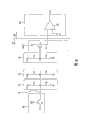
图6是根据本发明示例性实施例的连接至液晶显示器中的检测数据线的多个感测单元的等效电路图;6 is an equivalent circuit diagram of a plurality of sensing units connected to detection data lines in a liquid crystal display according to an exemplary embodiment of the present invention;
图7是根据本发明示例性实施例的触摸确定单元的框图;以及7 is a block diagram of a touch determination unit according to an exemplary embodiment of the present invention; and
图8是示出根据本发明示例性实施例的触摸确定单元的操作的流程图。FIG. 8 is a flowchart illustrating operations of a touch determination unit according to an exemplary embodiment of the present invention.
具体实施方式Detailed ways
下面,将参照附图更详细地描述本发明,其中,示出了本发明的示例性实施例。应当理解,当提到诸如层、膜、区域、或基板的元件“位于”另一个元件上时,其可以直接位于另一个元件上,或者也可能存在介于其间的元件。相反,当某个元件被提到“直接位于”另一个元件上时,意味着不存在介于其间的元件。In the following, the invention will be described in more detail with reference to the accompanying drawings, in which exemplary embodiments of the invention are shown. It will be understood that when an element such as a layer, film, region, or substrate is referred to as being "on" another element, it can be directly on the other element or intervening elements may also be present. In contrast, when an element is referred to as being "directly on" another element, there are no intervening elements present.
现在,将参照图1至图6详细描述根据本发明的显示装置的示例性实施例的液晶显示器。Now, a liquid crystal display according to an exemplary embodiment of a display device of the present invention will be described in detail with reference to FIGS. 1 to 6 .
图1是根据本发明示例性实施例的包括像素的液晶显示器的框图,图2是根据本发明示例性实施例的液晶显示器的像素的等效电路图,以及图3是根据本发明示例性实施例的示出感测单元的液晶显示器的框图。图4是根据本发明示例性实施例的液晶显示器的感测单元的等效电路图,以及图5是根据本发明示例性实施例的液晶显示器的示意图。图6是根据本发明示例性实施例的连接至液晶显示器中的感测数据线的多个感测单元的等效电路图。1 is a block diagram of a liquid crystal display including pixels according to an exemplary embodiment of the present invention, FIG. 2 is an equivalent circuit diagram of a pixel of a liquid crystal display according to an exemplary embodiment of the present invention, and FIG. 3 is an equivalent circuit diagram of a pixel according to an exemplary embodiment of the present invention. A block diagram of a liquid crystal display showing the sensing unit. 4 is an equivalent circuit diagram of a sensing unit of a liquid crystal display according to an exemplary embodiment of the present invention, and FIG. 5 is a schematic diagram of a liquid crystal display according to an exemplary embodiment of the present invention. FIG. 6 is an equivalent circuit diagram of a plurality of sensing units connected to sensing data lines in a liquid crystal display according to an exemplary embodiment of the present invention.
参照图1和图3,根据本发明示例性实施例的液晶显示器包括液晶面板组件300、连接至面板组件300的栅极驱动器400、数据驱动器500和感测信号处理器800、连接至数据驱动器500的灰度电压发生器550、连接至感测信号处理器800的触摸确定单元700、以及控制上述元件的信号控制器600。Referring to FIGS. 1 and 3 , a liquid crystal display according to an exemplary embodiment of the present invention includes a liquid
参照图1至图3,液晶面板组件300包括:多条显示信号线G1-Gn和D1-Dm以及与其连接并基本呈矩形配置的多个像素PX;多条感测信号线SY1-SYN和SX1-SXM以及与其连接并基本呈矩形配置的多个感测单元SU;多个复位信号输入单元IN1,分别连接至每条感测信号线SY1-SYN和SX1-SXM的一端;多个感测信号输出单元SOUT,分别连接至每条感测信号线SY1-SYN和SX1-SXM的另一端;以及多条输出数据线OY1-OYN和OX1-OXM,分别连接至每个感测信号输出单元SOUT。Referring to FIGS. 1 to 3 , the liquid
参照图2至图4,液晶面板组件300包括:彼此相对的薄膜晶体管阵列面板100和共电极面板200;介于其间的液晶层3;以及隔离件(未示出),在两个显示面板100和200之间形成间隙并在某种程度上可被压缩。2 to 4, the liquid
信号线G1-Gn和D1-Dm包括用于传送选通信号的多条栅极线G1-Gn和用于传送数据电压的多条数据线D1-Dm;感测信号线SY1-SYN、SX1-SXM和RL包括用于传送感测数据信号的多条行感测数据线SY1-SYN和多条列感测数据线SX1-SXM以及用于传送预定大小的基准电压的多条基准电压线RL。根据需要,可以省略基准电压线RL。The signal lines G1 -Gn and D1 -Dm include a plurality of gate lines G1 -Gn for transmitting gate signals and a plurality of data lines D1 -Dm for transmitting data voltages; The signal lines SY1 -SYN , SX1 -SXM and RL include a plurality of row sensing data lines SY1 -SYN and a plurality of column sensing data lines SX1 -SXM for transmitting sensing data signals, and A plurality of reference voltage lines RL for transmitting a reference voltage of a predetermined magnitude. The reference voltage line RL may be omitted as necessary.
栅极线G1-Gn和行感测数据线SY1-SYN近似在行方向上延伸,并且几乎彼此平行;以及数据线D1-Dm和列感测数据线SX1-SXM近似在列方向上延伸,并且几乎彼此平行。基准电压线RL在行方向或列方向上延伸。The gate lines G1 -Gn and the row sensing data lines SY1 -SYN approximately extend in the row direction and are almost parallel to each other; and the data lines D1 -Dm and the column sensing data lines SX1 -SXM approximately extend in the column direction and are almost parallel to each other. The reference voltage line RL extends in the row direction or the column direction.
如图2所示,每个像素PX(例如,连接至第i(i=1、2、...、n)条栅极线Gi和第j(j=1、2、...、m)条数据线Dj的像素PX)包括连接至信号线Gi和Dj的开关元件Q以及与其连接的液晶电容器Clc和存储电容器Cst。根据需要,可以省略存储电容器Cst。As shown in FIG. 2, each pixel PX (for example, connected to the i-th (i=1, 2, . . . , n) gate line Gi and the j-th (j=1, 2, . . . A pixel PX) of m) data linesDj includes a switching element Q connected to signal lines GiandDj , and a liquid crystal capacitor Clc and a storage capacitor Cst connected thereto. The storage capacitor Cst may be omitted as needed.
开关元件Q是诸如设置在薄膜晶体管阵列面板100中的薄膜晶体管的三端元件,其控制端连接至栅极线G1-Gn,其输入端连接至数据线D1-Dm,以及其输出端连接至液晶电容器Clc和存储电容器Cst。薄膜晶体管包括非晶硅和多晶硅。The switching element Q is a three-terminal element such as a thin film transistor provided in the thin film
液晶电容器Clc具有薄膜晶体管阵列面板100的像素电极191和共电极面板200的共电极270作为两端,并且两个电极191和270之间的液晶层3起电介质的功能。像素电极191连接至开关元件Q,共电极270形成在共电极面板200的整个表面上并接收共电压Vcom。与图2不同,共电极270可设置在薄膜晶体管阵列面板100上,在这种情况下,可以以线状或条状形成两个电极191和270中的至少一个。The liquid crystal capacitor Clc has the
存储电容器Cst为液晶电容器Clc的辅助电容器。通过单条信号线(未示出)和像素电极191的重叠形成存储电容器Cst,单条信号线和像素电极191设置在薄膜晶体管阵列面板100中并且其间具有绝缘体,并将诸如共电压Vcom的预定电压施加到单条信号线。然而,可通过像素电极191和经由绝缘体直接位于像素电极191上的先前栅极线的重叠形成存储电容器Cst。The storage capacitor Cst is an auxiliary capacitor for the liquid crystal capacitor Clc. The storage capacitor Cst is formed by overlapping a single signal line (not shown) and a
为了彩色显示,通过使每个像素PX固有地显示原色中的一个(空间分割)或者顺序交替地显示原色(时间分割),以原色的空间和时间组合识别期望的颜色。一组原色的实例包括红色、绿色、和蓝色。图2示出了每个像素PX均设置有用于在共电极面板200的对应于像素电极191的区域中显示原色中的一种的滤色片230作为空间分割的实例。与图2的情况不同,可在薄膜晶体管阵列面板100的像素电极191上或下形成滤色片230。For color display, a desired color is recognized in a spatial and temporal combination of primary colors by causing each pixel PX to inherently display one of the primary colors (spatial division) or sequentially and alternately display the primary colors (time division). An example of a set of primary colors includes red, green, and blue. FIG. 2 shows an example in which each pixel PX is provided with a
用于偏振光的至少一个偏光器(未示出)附着到液晶面板组件300的外表面。At least one polarizer (not shown) for polarizing light is attached to an outer surface of the liquid
图4示出了根据本发明示例性实施例的感测单元SU的实例,每个感测单元SU均包括:可变电容器Cv,连接至由参考标号SL表示的行或列感测数据线(下文中被称作“感测数据线”);或者基准电容器Cp,连接在感测数据线SL和基准电压线RL之间。4 shows an example of sensing units SU according to an exemplary embodiment of the present invention, each sensing unit SU includes: a variable capacitor Cv connected to a row or column sensing data line ( hereinafter referred to as "sensing data line"); or a reference capacitor Cp, connected between the sensing data line SL and the reference voltage line RL.
通过重叠薄膜晶体管阵列面板100的基准电压线RL和感测数据线SL(其间设置有电介质(未示出))形成基准电容器Cp。The reference capacitor Cp is formed by overlapping the reference voltage line RL and the sensing data line SL of the thin film
可变电容器Cv具有薄膜晶体管阵列面板100的感测数据线SL和共电极面板200的共电极270作为两端。液晶层3形成在薄膜晶体管阵列面板100和共电极面板200之间,并起到电介质的功能。可变电容器Cv的电容具有随着外部仿真(例如,施加到液晶面板组件300的用户触摸)而改变的值。作为外部仿真,以压力为例,如果压力被施加到共电极面板200,则隔离件被压缩变形,因此两端之间的距离改变,从而可变电容器Cv的电容改变。如果电容改变,则基准电容器Cp和可变电容器Cv之间的节点电压Vn的大小根据电容大小而改变。通过感测数据线SL传送作为感测数据信号的节点电压Vn,并且可基于节点电压Vn确定是否触摸。The variable capacitor Cv has the sensing data line SL of the thin film
参照图6,多个复位信号输入单元IN1中的每一个均具有相同的结构,并且均包括复位晶体管Qr。复位晶体管Qr是薄膜晶体管的三端元件,其控制端连接至复位控制信号RST,其输入端连接至复位电压Vr,以及其输出端连接至感测数据线(图3中的SX1-SXM或SY1-SYN)。根据复位控制信号RST,将复位电压Vr提供给感测数据线SL。Referring to FIG. 6, each of the plurality of reset signal input units IN1 has the same structure and includes a reset transistor Qr. The reset transistor Qr is a three-terminal element of a thin film transistor, its control terminal is connected to the reset control signal RST, its input terminal is connected to the reset voltage Vr, and its output terminal is connected to the sensing data line (SX1 -SXM in FIG. 3 or SY1 -SYN ). The reset voltage Vr is supplied to the sensing data line SL according to the reset control signal RST.
此外,多个感测信号输出单元SOUT中的每一个均具有相同的结构,并且均包括输出晶体管Qs。输出晶体管Qs是薄膜晶体管的三端元件,其控制端连接至感测信号线SL,其输入端连接至输入电压Vs,以及其输出端连接至输出数据线OL。基于流过感测数据线SL的感测数据信号生成输出信号。输出信号可以是输出电流。可选地,输出晶体管Qs可生成电压作为输出信号。In addition, each of the plurality of sensing signal output units SOUT has the same structure and includes an output transistor Qs. The output transistor Qs is a three-terminal element of a thin film transistor, its control terminal is connected to the sensing signal line SL, its input terminal is connected to the input voltage Vs, and its output terminal is connected to the output data line OL. The output signal is generated based on the sensing data signal flowing through the sensing data line SL. The output signal may be an output current. Alternatively, the output transistor Qs may generate a voltage as an output signal.
作为薄膜晶体管的复位晶体管Qr和输出晶体管Qs与开关元件Q一起形成。A reset transistor Qr and an output transistor Qs which are thin film transistors are formed together with the switching element Q. As shown in FIG.
输出数据线OY1-OYN和OX1-OXM包括多条行和列输出数据线OY1-OYN和OX1-OXM,其中的每一条都通过对应的感测信号输出单元SOUT分别连接至行和列感测数据线SY1-SYN和SX1-SXM。输出数据线OY1-OYN和OX1-OXM连接至感测信号处理器800,并将来自感测信号输出单元SOUT的输出信号传送至感测信号处理器800。行和列输出数据线OY1-OYN和OX1-OXM基本在行和列方向上延伸,并且基本彼此平行。The output data lines OY1 -OYN and OX1 -OXM include a plurality of row and column output data lines OY1 -OYN and OX1 -OXM , each of which is passed through the corresponding sensing signal output unit SOUT respectively Connect to row and column sense data lines SY1 -SYN and SX1 -SXM . The output data lines OY1 -OYN and OX1 -OXM are connected to the
再次参照图1,灰度电压发生器550生成所有灰度电压或预定量的灰度电压(下文中称作“基准灰度电压”),该灰度电压与像素PX的透光率相关。(基准)灰度电压可具有相对于共电压Vcom的正值或负值。Referring again to FIG. 1 , the
栅极驱动器400连接至液晶面板组件300的栅极线G1-Gn,并合成(synthesize)栅极导通电压Von和栅极截止电压Voff,以生成施加到栅极线G1-Gn的选通信号。The
数据驱动器500连接至液晶面板组件300的数据线D1-Dm,其选择来自灰度电压发生器550的灰度电压,并将选取的灰度电压作为数据电压施加到数据线D1-Dm。然而,当灰度电压发生器550仅生成一些基准灰度电压而不是全部灰度电压时,数据驱动器500可以划分基准灰度电压,以从基准灰度电压中生成数据电压。The
感测信号处理器800包括多个放大单元810,其连接至液晶面板组件300的输出数据线OY1-OYN和OX1-OXM。The
如图6所示,多个放大单元810中的每一个均具有相同的结构,并且每个放大单元810均包括放大器AP。放大器AP具有反相端(-)、非反相端(+)和输出端,反相端(-)连接至输出数据线OL,以及非反相端(+)连接至基准电压Va。每个放大单元810均使用放大器AP放大来自输出晶体管Qs的输出电流,从而生成感测信号Vo。As shown in FIG. 6, each of the plurality of amplifying
因此,感测信号处理器800使用模/数转换器(未示出)将来自放大单元810的模拟感测信号Vo转换为数字信号,并生成数字感测信号DSN。Accordingly, the
触摸确定单元700接收来自感测信号处理器800的数字感测信号DSN,以执行预定操作,来确定显示器是否被触摸以及触摸位置,然后将触摸信息INF发送到外部装置。触摸确定单元700基于数字感测信号DSN监控感测单元SU的状态。稍后将详细描述触摸确定单元700。The
信号控制器600控制栅极驱动器400、数据驱动器500、灰度电压发生器550和感测信号处理器800的操作。The
驱动装置400、500、550、600、700和800中的每一个都可以以至少一个集成电路(IC)芯片的形式直接安装在液晶面板组件300上,可以以带载封装(TCP)的形式安装在将附着至液晶面板组件300的柔性印刷电路膜(未示出)上,或者可安装在单独的印刷电路板(PCB)(未示出)上。可选地,驱动装置400、500、550、600、700和800可以与信号线G1-Gn、D1-Dm、SY1-SYN、SX1-SXM、OY1-OYN、OX1-OXM和RL以及薄膜晶体管Q一起集成到液晶面板组件300中。Each of the driving
参照图5,液晶面板组件300被分为显示区P1、边缘区P2和露出区P3。像素PX、感测单元SU、以及信号线G1-Gn、D1-Dm、SY1-SYN、SX1-SXM、OY1-OYN、OX1-OXM和RL中的大多数均位于显示区P1中。共电极面板200包括诸如黑矩阵的遮光构件(未示出),并且遮光构件覆盖了大部分边缘区P2,从而遮挡来自外部的光。像素PX不设置在边缘区P2中,但复位晶体管Qr和输出晶体管Qs位于其中。Referring to FIG. 5, the liquid
因为共电极面板200小于薄膜晶体管阵列面板100,所以薄膜晶体管阵列面板100的一部分形成露出区P3,将单个芯片610和柔性印刷电路板(FPC板)620一起安装在露出区P3中。Since the
单个芯片610包括用于驱动液晶显示器的驱动装置,即,栅极驱动器400、数据驱动器500、灰度电压发生器550、信号控制器600、触摸确定单元700和感测信号处理器800。通过将驱动装置400、500、550、600、700和800集成到信号芯片610中可减小安装区以及可降低功耗。根据需要,它们中的至少一个或者用于组成它们的至少一个电路元件可被设置在单个芯片610的外部。The
信号线G1-Gn和D1-Dm以及感测数据线SY1-SYN和SX1-SXM均被延伸到露出区P3,以连接至对应的驱动装置400、500和800。The signal lines G1 -Gn and D1 -Dm and the sensing data lines SY1 -SYN and SX1 -SXM are all extended to the exposed area P3 to be connected to the
FPC板620接收来自外部装置的信号,以将信号传送到单个芯片610或液晶面板组件300,FPC板620的边缘被形成为利于连接至外部装置的连接器(未示出)。The
现在,将详细描述液晶显示器的显示操作和感测操作。Now, the display operation and sensing operation of the liquid crystal display will be described in detail.
信号控制器600接收来自外部图形控制器(未示出)的输入图像信号R、G和B以及用于控制输入图像信号R、G和B的输入控制信号。输入图像信号R、G和B包括每个像素PX的亮度信息,并且亮度具有预定量的灰度,例如,1024(=210)、256(=28)、或64(=26)。例如,输入控制信号包括垂直同步信号Vsync、水平同步信号Hsync、主时钟信号MCLK以及数据使能信号DE。The
信号控制器600根据液晶面板组件300的操作条件基于输入图像信号R、G和B以及输入控制信号来适当地处理输入图像信号R、G和B,并生成栅极控制信号CONT1和数据控制信号CONT2,然后将栅极控制信号CONT1发送到栅极驱动器400,以及将数据控制信号CONT2和处理的图像信号DAT发送到数据驱动器500。The
栅极控制信号CONT1包括用于指示扫描开始的扫描开始信号STV以及用于控制栅极导通电压Von的输出周期的至少一个时钟信号。栅控控制信号CONT1还可以包括用于限制栅极导通电压Von的持续时间的输出使能信号OE。The gate control signal CONT1 includes a scan start signal STV for indicating scan start and at least one clock signal for controlling an output period of the gate-on voltage Von. The gate control signal CONT1 may further include an output enable signal OE for limiting the duration of the gate-on voltage Von.
数据控制信号CONT2包括用于通知开始传送像素PX的一行的数字图像信号DAT的水平同步开始信号STH、负载信号LOAD、以及用于将模拟数据电压施加到数据线D1-Dm的数据时钟信号HCLK。数据时钟信号CONT2还可以包括用于反转相对于共电压Vcom的数据电压的极性(下文中,“相对于共电压的数据电压的极性”被称作“数据电压极性”)的反转信号RVS。The data control signal CONT2 includes a horizontal synchronization start signal STH for notifying start of transfer of a digital image signal DAT of one row of pixels PX, a load signal LOAD, and a data clock signal for applying analog data voltages to the data linesD1 -Dm HCLK. The data clock signal CONT2 may further include an inversion for inverting the polarity of the data voltage with respect to the common voltage Vcom (hereinafter, “the polarity of the data voltage with respect to the common voltage” is referred to as “data voltage polarity”). Turn signal RVS.
数据驱动器500根据来自信号控制单元600的数据控制信号CONT2接收像素PX的一行的数字图像信号DAT,通过选择对应于每个数字图像信号DAT的灰度电压将数字图像信号DAT转换为模拟数据电压,然后将模拟数据电压施加到对应的数据线D1-Dm。The
栅极驱动器400根据来自信号控制单元600的栅极控制信号CONT1将栅极导通电压Von施加到栅极线G1-Gn,以使连接至栅极线G1-Gn的开关元件Q导通。因此,通过导通的开关元件Q将施加到数据线D1-Dm的数据电压施加到对应的像素PX。The
共电压Vcom和施加到像素PX的数据电压之间的差被表示为充电电压,即,液晶电容器Clc的像素电压。液晶分子根据像素电压的大小而具有不同的配置,使得穿过液晶层3的光的偏振改变。通过由偏振器实现的光透射率的改变来表示偏振的改变,从而像素PX显示以图像信号DAT的灰度所表示的亮度。A difference between the common voltage Vcom and the data voltage applied to the pixel PX is represented as a charging voltage, ie, a pixel voltage of the liquid crystal capacitor Clc. The liquid crystal molecules have different configurations according to the magnitude of the pixel voltage, so that the polarization of light passing through the
通过以一个水平周期单位(被称作“1H”,与水平同步信号Hsync和数据使能信号DE的一个周期相同)重复处理,栅极导通电压Von被顺序施加到所有栅极线G1-Gn,以及将数据电压施加到所有像素PX,从而显示一帧图像。The gate-on voltage Von is sequentially applied to all the gate lines G1 - Gn , and applying the data voltage to all the pixels PX, thereby displaying one frame of image.
控制施加到数据驱动器500的反转信号RVS状态,使得当一个帧结束时下一帧开始,并且施加到每个像素PX的数据电压的极性与前一帧的极性相反(“帧反转”)。还可以控制反转信号RVS,使得可以在一帧期间内周期性地反转流过一条数据线的数据电压的极性(例如,行反转和点反转),或者可以反转施加一个像素行的一个封装中的数据电压的极性(例如,列反转和点反转)。The state of the inversion signal RVS applied to the
感测信号处理器800根据复位信号RST通过将复位电压Vr施加到感测信号线SL来初始化感测信号线SL,然后根据共电压Vcom的状态从输出感测线OL中读取放大的感测数据信号。感测信号处理器800再次放大所读取放大的感测数据信号,然后将信号转换为数字感测信号并将该信号传送到触摸确定单元700。The
感测信号处理器800通过感测数据控制信号CONT3读取在预定周期内(例如,每帧一次)在帧之间通过输出数据线OY1-OYN和OX1-OXM施加的感测数据信号。然而,不必在每帧中都执行这种读取操作,根据需要可在多个帧中逐个执行读取操作。此外,可以在预定周期中执行至少两个读取操作。The
参照图6,详细描述感测数据信号的读取操作。Referring to FIG. 6 , the read operation of the sensing data signal is described in detail.
当通过复位信号RST来使复位晶体管Qr导通时,施加具有对应大小的复位电压Vr来初始化感测线SL。当在预定时间之后通过复位信号RST来使复位晶体管Qr截止时,感测线SL与复位电压Vr电断开。根据感测单元SU的“触摸或不触摸”状态,基于共电压Vcom的改变和可变电容器Cv的电容改变来改变施加到输出晶体管Qs的控制端的电压。根据电压改变,改变流向输出晶体管Qs的感测数据信号的电流大小。When the reset transistor Qr is turned on by the reset signal RST, a reset voltage Vr having a corresponding magnitude is applied to initialize the sensing line SL. When the reset transistor Qr is turned off by the reset signal RST after a predetermined time, the sensing line SL is electrically disconnected from the reset voltage Vr. The voltage applied to the control terminal of the output transistor Qs is changed based on the change of the common voltage Vcom and the capacitance change of the variable capacitor Cv according to the "touch or no touch" state of the sensing unit SU. According to the voltage change, the magnitude of the current of the sensing data signal flowing to the output transistor Qs is changed.
此外,感测信号处理器800读取感测信号Vo。In addition, the
因为基于复位电压Vr来改变感测数据信号,所以感测信号通通常将具有使得可容易地确定“触摸或不触摸”状态以及触摸位置的恒定范围内的电压电平。Because the sense data signal is changed based on the reset voltage Vr, the sense signal will generally have a voltage level within a constant range such that the "touch or no touch" state and touch location can be easily determined.
在使用每个放大单元810读取模拟感测数据信号之后,感测信号处理器800将感测信号Vo转换为数字感测信号DSN,并将转换的数字信号发送到触摸确定单元700。After reading the analog sensing data signal using each
触摸确定单元700接收数字感测信号DSN,以确定触摸发生和触摸位置,并将其结果发送到外部装置。外部装置基于结果将图像信号R、G和B传送到液晶显示器,因此显示由用户选择的屏幕、菜单等。The
下文中,将参照图7和图8详细描述根据本发明示例性实施例的触摸确定单元700的操作。Hereinafter, the operation of the
图7是根据本发明示例性实施例的触摸确定单元700的框图,以及图8是示出根据本发明示例性实施例的触摸确定单元700的操作的流程图。FIG. 7 is a block diagram of a
参照图7,触摸确定单元700包括缓冲器单元710、信号处理器720、触摸状态确定单元730、控制器740、寄存器单元750、触摸生成信号发生器760和触摸信息输出单元770。Referring to FIG. 7 , the
如下操作触摸确定单元700。The
当触摸确定单元700的操作开始(S10)时,触摸确定单元700的缓冲器单元710读取并存储由感测信号处理器800施加的多个感测信号DSN(步骤S11和S12)。When the operation of the
此后,信号处理器720将读取感测信号DSN处理为可用信号,并将处理的感测信号存储在缓冲器单元710中(步骤S12)。接下来,触摸状态确定单元730确定是否发生了触摸以及使用存储在缓冲器单元710中的感测信号确定触摸次数,并生成触摸位置的X轴和Y轴位置数据(步骤S13)。Thereafter, the signal processor 720 processes the read sensing signal DSN into an available signal, and stores the processed sensing signal in the buffer unit 710 (step S12). Next, the touch
表示触摸发生的感测信号的值为“1”,以及表示触摸未发生的感测信号的值为“0”。触摸状态确定单元730确定是否存在具有值“1”的感测信号,并基于具有值“1”的感测信号的位置确定触摸次数,并生成位置数据。A value of the sensing signal indicating that a touch occurs has a value of "1", and a value of a sensing signal indicating that a touch has not occurred is "0". The touch
当在X轴或Y轴方向附近的所有预定数目的感测信号都具有值“1”(即,表现为触摸状态)时,触摸状态确定单元730识别为单个触摸。When all of the predetermined number of sensing signals near the X-axis or Y-axis direction have a value of '1' (ie, represent a touch state), the touch
此外,当多个感测信号顺序具有值“1”时,触摸状态确定单元730可基于多个感测信号中的一个来生成位置数据。Also, when the plurality of sensing signals sequentially have a value of '1', the touch
接下来,控制器740基于来自触摸状态确定单元730的数据和存储在寄存器单元750中的几个标志值来确定触摸位置。Next, the
即,控制器确定是否发生触摸(步骤S14)。That is, the controller determines whether a touch occurs (step S14).
当没有发生触摸时,控制器740将两个触摸标志touch1和touch2(用于表示是否发生触摸的标志)的值设置为“0”(非激活状态);将顺序触摸标志SeqTouch的值设置为“0”(非激活状态);以及将标志touch1、touch2和SeqTouch的值存储在寄存器单元750中(步骤S15和S16)。When no touch occurs, the
此后,控制器740进行到步骤S17。Thereafter, the
因为没有发生触摸,所以控制器740将通过触摸生成信号发生器760输出的触摸生成信号TE的状态设置为非触摸状态,以通知没有发生触摸,并且不通过触摸信息输出单元770输出诸如触摸位置和触摸次数的触摸信息INF。例如,表示非触摸状态的触摸生成信号TE的状态可以是低电平,并且表示触摸状态的触摸生成信号TE的状态可以是高电平;然而,表示非触摸状态的触摸生成信号TE的状态可以是高电平,并且表示触摸状态的触摸生成信号TE的状态可以是低电平。Because no touch occurs, the
当在步骤S14处发生了触摸时,控制器740确定触摸次数是否为“1”(步骤S18)。When a touch has occurred at step S14, the
当触摸次数为“1”时,控制器740将触摸标志touch1的值设置为“1”(激活状态);将触摸标志touch2的值设置为“0”(非激活状态);以及将标志touch1和touch2的值存储在寄存器单元750中(步骤S19)。When the number of touches is "1", the
在该实施例中,当只有触摸标志touch1具有值“1”时,表示发生了一次触摸,以及当两个触摸标志touch1和touch2均具有值“1”时,表示发生了两次触摸。In this embodiment, when only the touch flag touch1 has a value of "1", it indicates that one touch has occurred, and when both touch flags touch1 and touch2 have a value of "1", it indicates that two touches have occurred.
在该实施例中,因为最大将同时触摸的触摸点数设置为2,所以触摸标志touch1和touch2的数为“2”;然而,可以改变同时触摸的触摸点数,并且也可以改变触摸标志的数。In this embodiment, since the maximum number of simultaneously touched touch points is set to 2, the number of touch marks touch1 and touch2 is "2"; however, the number of simultaneously touched touch points may be changed, and the number of touch marks may also be changed.
此后,控制器740将顺序触摸标志SeqTouch的值改变为“1”,并将该值存储在寄存器单元750中(步骤S20)。当基于顺序触摸标志SeqTouch的值同时检测到两个或多个触摸点时,控制器740可以确定是否顺序发生触摸,即,在每帧中逐个进行。此外,控制器740将X轴和Y轴位置信息标志XPosFix和YPosFix的值设置为“0”(非激活状态),并将值存储在寄存器单元750中(步骤S20)。Thereafter, the
此后,在步骤S17中,控制器740分别通过触摸生成信号发生器760和触摸信息输出单元770输出对应状态的触摸生成信号TE和触摸信息INF。即,因为发生了一次触摸,所以控制器740将触摸生成信号TE的状态设置为触摸状态,通过触摸生成信号发生器760输出该状态,并通过触摸信息输出单元770输出当前触摸的位置数据和触摸次数“1”。在这种情况下,触摸生成信号TE和触摸信息INF可通过诸如串行接口(SPI)和I2C的接口来传送。Thereafter, in step S17, the
如果在步骤S18处的触摸次数不为“1”,则控制器760确定触摸次数为“2”(步骤S21)。If the number of touches at step S18 is not "1", the
接下来,控制器740确定存储在寄存器单元750中的顺序触摸标志SeqTouch的值是否为“1”(步骤S22)。Next, the
当顺序触摸标志SeqTouch的值为“0”而不是“1”时,控制器740确定在一帧中发生了两次触摸,而不是在两帧中一个接一个地顺序发生两次触摸。在这种情况下,因为不能确定精确的触摸位置,因此控制器740不确定触摸位置。When the value of the sequential touch flag SeqTouch is '0' instead of '1', the
因此,控制器740将所有触摸标志touch1和touch2的值都设置为“0”,并将值保存在寄存器单元750中(步骤S23),并通过触摸生成信号发生器760输出非触摸状态的触摸生成信号TE(步骤S30)。在这种情况下,不输出触摸位置和触摸次数的数据。此后,控制器740初始化诸如顺序触摸标志SeqTouch的变量的值(步骤S31)。Therefore, the
当顺序触摸标志SeqTouch的值为“1”时,由于在先前帧中发生的一次触摸(下文中称作“先前触摸”)被保持并且在当前帧中发生了一次触摸(下文中称作“当前触摸”),所以控制器740确定发生了两次触摸。When the value of the sequential touch flag SeqTouch is "1", since a touch (hereinafter referred to as "previous touch") that occurred in the previous frame is held and a touch occurs in the current frame (hereinafter referred to as "current touch") touch"), so the
因此,控制器740确定是否存在两个X轴位置数据(步骤S24)。Therefore, the
当不存在两个X轴位置数据时(即,当仅存在一个X轴位置数据时),控制器740确定存在两个Y轴位置数据(步骤S25)。即,控制器740确定两个触摸的X轴位置数据的值相等,而两次触摸的Y轴位置数据的值不同,因为在相同的列中发生了两次触摸。When there are no two X-axis position data (ie, when there is only one X-axis position data), the
因此,控制器740将两次触摸标志touch1和touch2的值设置为“1”,将X轴位置信息标志XPosFix的值设置为“1”,并将值存储在寄存器单元750中(步骤S26)。此外,控制器740读取存储在诸如存储器的存储装置(未示出)中的先前触摸的位置数据,将先前触摸的X轴位置数据设置为当前触摸的X轴位置数据,将与先前触摸的Y轴位置数据不同的新值设置为当前触摸的Y轴位置数据,并将值存储在存储装置中(步骤S26)。Therefore, the
可选地,控制器740可使用缓冲器单元710、寄存器单元750、或单个存储装置存储先前触摸的位置数据。Alternatively, the
此后,控制器740进行到步骤S30,以将触摸生成信号TE的状态设置为触摸状态,并通过触摸生成信号发生器760输出信号TE。此外,控制器740分别通过触摸信息输出单元770输出先前触摸的读取X轴和Y轴位置数据和当前触摸的设置X轴和Y轴位置数据以及输出“2”作为两个触摸数据和触摸次数(步骤S17)。在这种情况下,还输出X轴位置信息标志XPosFix的值,使得可以通知当前触摸发生在与先前触摸相同的列中。此后,在步骤S31中,控制器740将变量Touch1、Touch2、XPosFix和SeqTouch的值初始化为“0”。Thereafter, the
当在步骤S24处存在两个X轴位置数据时,控制器740确定是否存在两个Y轴位置数据(步骤S27)。When there are two X-axis position data at step S24, the
当不存在两个Y轴位置数据时,X轴位置数据的次数为“2”,而Y轴位置数据的次数为“1”。When there are no two Y-axis position data, the number of X-axis position data is "2", and the number of Y-axis position data is "1".
因此,控制器740确定在相同的行中发生了两次触摸,即,Y轴位置数据的值相等,而X轴位置数据的值不同。因此,控制器740将两个触摸标志touch1和touch2的值设置为“1”,将Y轴位置信息标志YPosFix的值设置为“1”,并将值存储在寄存器单元750中(步骤S28)。此外,控制器740读取存储在存储装置中的先前触摸的位置数据,将先前触摸的Y轴位置数据设置为当前触摸的Y轴位置数据,将与先前触摸的X轴位置数据不同的新值设置为当前触摸的X轴位置数据,并将值存储在存储装置中(步骤S28)。Therefore, the
此后,在步骤S30处,控制器740将触摸生成信号TE的状态设置为触摸状态,通过触摸生成信号发生器760输出信号TE,并通过触摸信息输出单元770分别输出先前触摸的读取X轴和Y轴位置数据和当前触摸的设置X轴和Y轴位置数据以及输出“2”作为两次触摸数据和触摸次数。在这种情况下,还输出Y轴位置信息标志YPosFix的值,使得可以通知当前触摸发生在与先前触摸相同的行中,并且在步骤S31处,将变量Touch1、Touch2、YPosFix和SeqTouch的值初始化为“0”。Thereafter, at step S30, the
如果在步骤S27处存在两个Y轴位置数据,则存在两个不同的X轴和Y轴位置数据。因此,控制器740将两个触摸标志touch1和touch2的值设置为“1”,并将值存储在寄存器单元750中,将与存储在存储装置中的先前触摸的X轴和Y轴位置数据不同的值设置为当前触摸的X轴和Y轴位置数据,并存储值(步骤S29)。If there are two Y-axis position data at step S27, there are two different X-axis and Y-axis position data. Therefore, the
此后,在步骤S30处,控制器740将触摸生成信号TE的状态设置为触摸状态,通过触摸生成信号发生器760输出信号TE,并通过触摸信息输出单元770分别输出先前触摸的X轴和Y轴位置数据和当前触摸的X轴和Y轴位置数据以及输出“2”作为两次触摸数据和触摸次数,以及在步骤S31处,将变量Touch1、Touch2、XPosFix、YPosFix和SeqTouch的值初始化为“0”。Thereafter, at step S30, the
在该实施例中,最大将同时检测的触摸次数设置为2,然而,触摸次数不限于此,而是可将同时检测的触摸次数设置为3以上。In this embodiment, the maximum number of simultaneously detected touches is set to 2, however, the number of touches is not limited thereto, and the number of simultaneously detected touches may be set to 3 or more.
为了通过上述方式确定触摸位置,只需要列感测信号线SX1-SXM和行感测信号线SY1-SYN的位置数据。In order to determine the touch position in the above manner, only the position data of the column sensing signal lines SX1 -SXM and the row sensing signal lines SY1 -SYN are needed.
然而,在现有技术中,各个列或行感测信号线SX1-SXM或SY1-SYN的位置数据和对应于该位置数据的所有列或行感测信号线SY1-SYN或SX1-SXM的位置数据均被顺序地单独进行处理,由此确定是否触摸和触摸位置。因此,在现有技术中,为了确定触摸位置,需要比该实施例的情况更多的数据,从而需要更多的数据处理时间。However, in the prior art, the position data of each column or row sensing signal line SX1 -SXM or SY1 -SYN and all column or row sensing signal lines SY1 -SYN corresponding to the position data Or the position data of SX1 -SXM are sequentially and individually processed, thereby determining whether to touch or not and the touch position. Therefore, in the prior art, in order to determine the touch position, more data is required than in the case of this embodiment, thus requiring more data processing time.
在该实施例中,作为感测单元,以使用可变电容器和基准电容器的感测单元为例,然而,感测单元不限于此并且可以使用不同类型的感测单元。例如,可以使用压敏单元,该压敏单元使用共电极面板的共电极和薄膜晶体管阵列面板的感测数据线作为其两端,其至少一端被设计为突出,并且当通过用户触摸来使两端物理或电连接时输出共电压作为输出信号。此外,可以使用根据光的强度输出不同信号的光学传感器。此外,本发明可应用于包括两种或多种感测单元的显示装置。In this embodiment, as the sensing unit, a sensing unit using a variable capacitor and a reference capacitor is exemplified, however, the sensing unit is not limited thereto and a different type of sensing unit may be used. For example, a pressure-sensitive unit can be used, which uses the common electrode of the common electrode panel and the sensing data line of the thin film transistor array panel as its two ends, at least one end of which is designed to protrude, and when touched by the user to make the two When the terminals are physically or electrically connected, a common voltage is output as an output signal. In addition, an optical sensor that outputs a different signal according to the intensity of light may be used. In addition, the present invention is applicable to a display device including two or more kinds of sensing units.
此外,在该实施例中,作为显示装置,以液晶显示器为例,然而,显示装置不限于此,而是可以等效地用在诸如等离子显示装置或有机发光装置的平板显示器中。Also, in this embodiment, as the display device, a liquid crystal display is exemplified, however, the display device is not limited thereto but may be equivalently used in a flat panel display such as a plasma display device or an organic light emitting device.
根据本发明,仅使用通过多条行感测信号线和多条列感测信号线输出的感测信号就可精确确定是否触摸了感测单元以及触摸位置。According to the present invention, whether a sensing unit is touched and a touched position can be accurately determined using only sensing signals output through a plurality of row sensing signal lines and a plurality of column sensing signal lines.
此外,代替使用对应于每条行或列感测信号线的所有列或行感测信号线的感测信号,仅使用行和列感测信号线的感测信号来确定是否触摸以及触摸位置,使得减小了数据处理量并且还减小了数据处理时间。Furthermore, instead of using the sensing signals of all the column or row sensing signal lines corresponding to each row or column sensing signal line, only the sensing signals of the row and column sensing signal lines are used to determine whether to touch and the touched position, This results in a reduction in the amount of data processing and also reduces the data processing time.
虽然连同当前被认为是实践示例性实施例描述了本发明,但应当理解,本发明不限于公开的实施例,相反地,覆盖包括在所附权利要求的精神和范围内的各种更改和等效配置。While the invention has been described in connection with what is presently considered to be practical exemplary embodiments, it is to be understood that the invention is not limited to the disclosed embodiments, but on the contrary covers various modifications and equivalents included within the spirit and scope of the appended claims. effective configuration.
Claims (22)
Applications Claiming Priority (3)
| Application Number | Priority Date | Filing Date | Title |
|---|---|---|---|
| KR1020070022669AKR101383709B1 (en) | 2007-03-07 | 2007-03-07 | Display device and driving method thereof |
| KR1020070022669 | 2007-03-07 | ||
| KR10-2007-0022669 | 2007-03-07 |
Publications (2)
| Publication Number | Publication Date |
|---|---|
| CN101261553Atrue CN101261553A (en) | 2008-09-10 |
| CN101261553B CN101261553B (en) | 2013-04-24 |
Family
ID=39741158
Family Applications (1)
| Application Number | Title | Priority Date | Filing Date |
|---|---|---|---|
| CN2007101953781AActiveCN101261553B (en) | 2007-03-07 | 2007-12-13 | Display device and method of driving the same |
Country Status (4)
| Country | Link |
|---|---|
| US (1) | US8736556B2 (en) |
| JP (1) | JP5485512B2 (en) |
| KR (1) | KR101383709B1 (en) |
| CN (1) | CN101261553B (en) |
Cited By (14)
| Publication number | Priority date | Publication date | Assignee | Title |
|---|---|---|---|---|
| CN101996012A (en)* | 2009-08-25 | 2011-03-30 | 安华高科技Ecbuip(新加坡)私人有限公司 | Firmware method and apparatus for mutual capacitive touch sensing device |
| WO2011041948A1 (en)* | 2009-10-09 | 2011-04-14 | 禾瑞亚科技股份有限公司 | Method and apparatus for analyzing location |
| CN102455808A (en)* | 2010-10-22 | 2012-05-16 | 瑞鼎科技股份有限公司 | Detection method and detection device for detecting multiple touch points on touch panel |
| CN102467305A (en)* | 2010-11-19 | 2012-05-23 | 矽统科技股份有限公司 | Electronic device with capacitive sensing circuit carrying phase information and method thereof |
| CN102467275A (en)* | 2010-11-10 | 2012-05-23 | 瑞鼎科技股份有限公司 | Detection method and detection device for detecting a plurality of touch points on touch panel |
| US8471826B2 (en) | 2009-10-09 | 2013-06-25 | Egalax—Empia Technology Inc. | Method and device for position detection |
| US8583401B2 (en) | 2009-10-09 | 2013-11-12 | Egalax—Empia Technology Inc. | Method and device for analyzing positions |
| US8816979B2 (en) | 2009-10-09 | 2014-08-26 | Egalax—Empia Technology Inc. | Method and device for determining a touch or touches |
| US8872776B2 (en) | 2009-10-09 | 2014-10-28 | Egalax—Empia Technology Inc. | Method and device for analyzing two-dimension sensing information |
| US8890821B2 (en) | 2009-10-09 | 2014-11-18 | Egalax—Empia Technology Inc. | Method and device for dual-differential sensing |
| CN104835415A (en)* | 2014-02-12 | 2015-08-12 | 三星显示有限公司 | Display device |
| US9734769B2 (en) | 2014-07-04 | 2017-08-15 | Japan Display Inc. | Display apparatus and method of driving the same |
| US9864471B2 (en) | 2009-10-09 | 2018-01-09 | Egalax_Empia Technology Inc. | Method and processor for analyzing two-dimension information |
| CN109725779A (en)* | 2017-09-29 | 2019-05-07 | 三星电子株式会社 | Touch detection device and method of detecting touch |
Families Citing this family (30)
| Publication number | Priority date | Publication date | Assignee | Title |
|---|---|---|---|---|
| US20080168402A1 (en) | 2007-01-07 | 2008-07-10 | Christopher Blumenberg | Application Programming Interfaces for Gesture Operations |
| US20080168478A1 (en) | 2007-01-07 | 2008-07-10 | Andrew Platzer | Application Programming Interfaces for Scrolling |
| US7844915B2 (en) | 2007-01-07 | 2010-11-30 | Apple Inc. | Application programming interfaces for scrolling operations |
| KR101383715B1 (en)* | 2007-06-21 | 2014-04-09 | 삼성디스플레이 주식회사 | Touch sensible display device, and driving method thereof |
| KR101542397B1 (en)* | 2007-12-10 | 2015-08-06 | 삼성디스플레이 주식회사 | Display device having contact detection function and driving method thereof |
| US8717305B2 (en) | 2008-03-04 | 2014-05-06 | Apple Inc. | Touch event model for web pages |
| US8645827B2 (en) | 2008-03-04 | 2014-02-04 | Apple Inc. | Touch event model |
| US8174502B2 (en) | 2008-03-04 | 2012-05-08 | Apple Inc. | Touch event processing for web pages |
| US8416196B2 (en) | 2008-03-04 | 2013-04-09 | Apple Inc. | Touch event model programming interface |
| KR100976527B1 (en)* | 2008-10-14 | 2010-08-17 | 하이디스 테크놀로지 주식회사 | LCD with touch screen function using photoconductor |
| KR101513440B1 (en)* | 2008-12-01 | 2015-04-22 | 삼성디스플레이 주식회사 | Touch screen display device and manufacturing method thereof |
| US8285499B2 (en) | 2009-03-16 | 2012-10-09 | Apple Inc. | Event recognition |
| US8566044B2 (en)* | 2009-03-16 | 2013-10-22 | Apple Inc. | Event recognition |
| US8566045B2 (en) | 2009-03-16 | 2013-10-22 | Apple Inc. | Event recognition |
| US9311112B2 (en) | 2009-03-16 | 2016-04-12 | Apple Inc. | Event recognition |
| US9684521B2 (en) | 2010-01-26 | 2017-06-20 | Apple Inc. | Systems having discrete and continuous gesture recognizers |
| TWI419034B (en)* | 2009-04-03 | 2013-12-11 | Novatek Microelectronics Corp | A control method of detecting a touch event for a touch panel and related device |
| KR101048447B1 (en)* | 2009-10-30 | 2011-07-11 | 화영시스템즈주식회사 | Gesture registration device and method for NVI |
| JP5271240B2 (en)* | 2009-11-25 | 2013-08-21 | 株式会社デジタル | Touch panel device |
| JP4727753B1 (en) | 2010-03-04 | 2011-07-20 | Smk株式会社 | Capacitive touch panel |
| US10216408B2 (en) | 2010-06-14 | 2019-02-26 | Apple Inc. | Devices and methods for identifying user interface objects based on view hierarchy |
| US9298363B2 (en) | 2011-04-11 | 2016-03-29 | Apple Inc. | Region activation for touch sensitive surface |
| US20130082936A1 (en)* | 2011-09-29 | 2013-04-04 | Sharp Kabushiki Kaisha | Sensor array with high linearity |
| US9733716B2 (en) | 2013-06-09 | 2017-08-15 | Apple Inc. | Proxy gesture recognizer |
| KR102082936B1 (en)* | 2013-10-21 | 2020-04-14 | 엘지디스플레이 주식회사 | Touch sensing system and driving method thereof |
| KR102114488B1 (en)* | 2013-11-05 | 2020-05-25 | 엘지디스플레이 주식회사 | Touch sensing system and display device |
| JP6472196B2 (en)* | 2014-09-17 | 2019-02-20 | 株式会社ワコム | Sensor signal processing circuit and sensor signal processing method |
| TWI588699B (en)* | 2015-10-13 | 2017-06-21 | 友達光電股份有限公司 | Touch display apparatus and shift register thereof |
| TWI588810B (en)* | 2015-11-27 | 2017-06-21 | 友達光電股份有限公司 | Display driving method and mobile apparatus thereof |
| CN114442847B (en)* | 2022-01-18 | 2024-01-30 | Tcl华星光电技术有限公司 | Screen touch point positioning method, device, computer-readable medium and electronic equipment |
Family Cites Families (13)
| Publication number | Priority date | Publication date | Assignee | Title |
|---|---|---|---|---|
| JPS61118826A (en) | 1984-11-14 | 1986-06-06 | Omron Tateisi Electronics Co | Touch panel device |
| JP3469912B2 (en) | 1992-11-18 | 2003-11-25 | 株式会社デジタル | Touch panel input device and input method capable of multiple simultaneous inputs |
| JP3349223B2 (en) | 1993-10-13 | 2002-11-20 | 株式会社デジタル | Pointed coordinate detection method and device |
| JP2002055781A (en)* | 2000-08-14 | 2002-02-20 | Canon Inc | INFORMATION PROCESSING APPARATUS AND CONTROL METHOD THEREOF, COMPUTER READABLE MEMORY |
| JP2002259035A (en)* | 2001-02-28 | 2002-09-13 | Sony Corp | Graphical user interface, operation method for information processor, the information processor, recording medium, and program |
| JP2003099205A (en) | 2001-09-21 | 2003-04-04 | Ricoh Co Ltd | Display integrated type coordinate input device |
| US20050052427A1 (en)* | 2003-09-10 | 2005-03-10 | Wu Michael Chi Hung | Hand gesture interaction with touch surface |
| US7864161B2 (en)* | 2004-06-17 | 2011-01-04 | Adrea, LLC | Use of a two finger input on touch screens |
| KR20060012200A (en)* | 2004-08-02 | 2006-02-07 | 삼성전자주식회사 | Display device and driving method thereof |
| KR101085447B1 (en) | 2004-12-31 | 2011-11-21 | 삼성전자주식회사 | Touch position detection device and touch position detection method thereof, and touch screen display device having the same |
| KR20070048393A (en)* | 2005-11-04 | 2007-05-09 | 삼성전자주식회사 | Display and liquid crystal display |
| JP4628178B2 (en)* | 2005-05-16 | 2011-02-09 | 任天堂株式会社 | Information processing apparatus and item selection processing program |
| US7907125B2 (en)* | 2007-01-05 | 2011-03-15 | Microsoft Corporation | Recognizing multiple input point gestures |
- 2007
- 2007-03-07KRKR1020070022669Apatent/KR101383709B1/enactiveActive
- 2007-10-30USUS11/928,753patent/US8736556B2/enactiveActive
- 2007-12-13CNCN2007101953781Apatent/CN101261553B/enactiveActive
- 2008
- 2008-02-14JPJP2008032906Apatent/JP5485512B2/enactiveActive
Cited By (37)
| Publication number | Priority date | Publication date | Assignee | Title |
|---|---|---|---|---|
| CN101996012A (en)* | 2009-08-25 | 2011-03-30 | 安华高科技Ecbuip(新加坡)私人有限公司 | Firmware method and apparatus for mutual capacitive touch sensing device |
| CN107831956B (en)* | 2009-08-25 | 2020-09-01 | 原相科技股份有限公司 | Method for improving noise robustness and navigation performance in mutual capacitance sensing device |
| CN107831956A (en)* | 2009-08-25 | 2018-03-23 | 原相科技股份有限公司 | The method of noise robustness and navigation performance in improvement mutual capacitance measuring device |
| CN101996012B (en)* | 2009-08-25 | 2015-04-22 | 原相科技股份有限公司 | Firmware method and apparatus for mutual capacitive touch sensing device |
| US8600698B2 (en) | 2009-10-09 | 2013-12-03 | Egalax—Empia Technology Inc. | Method and device for analyzing positions |
| US10101372B2 (en) | 2009-10-09 | 2018-10-16 | Egalax_Empia Technology Inc. | Method and device for analyzing positions |
| US8564564B2 (en) | 2009-10-09 | 2013-10-22 | Egalax—Empia Technology Inc. | Method and device for position detection |
| US8570289B2 (en) | 2009-10-09 | 2013-10-29 | Egalax—Empia Technology Inc. | Method and device for position detection |
| US8583401B2 (en) | 2009-10-09 | 2013-11-12 | Egalax—Empia Technology Inc. | Method and device for analyzing positions |
| WO2011041948A1 (en)* | 2009-10-09 | 2011-04-14 | 禾瑞亚科技股份有限公司 | Method and apparatus for analyzing location |
| US8816979B2 (en) | 2009-10-09 | 2014-08-26 | Egalax—Empia Technology Inc. | Method and device for determining a touch or touches |
| US8842079B2 (en) | 2009-10-09 | 2014-09-23 | Egalax—Empia Technology Inc. | Method and device for determining a touch or touches |
| US8872776B2 (en) | 2009-10-09 | 2014-10-28 | Egalax—Empia Technology Inc. | Method and device for analyzing two-dimension sensing information |
| US8890821B2 (en) | 2009-10-09 | 2014-11-18 | Egalax—Empia Technology Inc. | Method and device for dual-differential sensing |
| US8941597B2 (en) | 2009-10-09 | 2015-01-27 | Egalax—Empia Technology Inc. | Method and device for analyzing two-dimension sensing information |
| US8970552B2 (en) | 2009-10-09 | 2015-03-03 | Egalax—Empia Technology Inc. | Method and device for position detection |
| US8970551B2 (en) | 2009-10-09 | 2015-03-03 | Egalax—Empia Technology Inc. | Method and device for position detection |
| US10310693B2 (en) | 2009-10-09 | 2019-06-04 | Egalax_Empia Technology Inc. | Controller for position detection |
| US8471826B2 (en) | 2009-10-09 | 2013-06-25 | Egalax—Empia Technology Inc. | Method and device for position detection |
| US9069410B2 (en) | 2009-10-09 | 2015-06-30 | Egalax—Empia Technology Inc. | Method and device for analyzing two-dimension sensing information |
| US9081441B2 (en) | 2009-10-09 | 2015-07-14 | Egalax—Empia Technology Inc. | Method and device for analyzing two-dimension sensing information |
| US9977556B2 (en) | 2009-10-09 | 2018-05-22 | Egalax_Empia Technology Inc. | Controller for position detection |
| US9285940B2 (en) | 2009-10-09 | 2016-03-15 | Egalax—Empia Technology Inc. | Method and device for position detection |
| US9606692B2 (en) | 2009-10-09 | 2017-03-28 | Egalax_Empia Technology Inc. | Controller for position detection |
| US9864471B2 (en) | 2009-10-09 | 2018-01-09 | Egalax_Empia Technology Inc. | Method and processor for analyzing two-dimension information |
| US9798427B2 (en) | 2009-10-09 | 2017-10-24 | Egalax_Empia Technology Inc. | Method and device for dual-differential sensing |
| CN102455808A (en)* | 2010-10-22 | 2012-05-16 | 瑞鼎科技股份有限公司 | Detection method and detection device for detecting multiple touch points on touch panel |
| CN102467275A (en)* | 2010-11-10 | 2012-05-23 | 瑞鼎科技股份有限公司 | Detection method and detection device for detecting a plurality of touch points on touch panel |
| CN102467305B (en)* | 2010-11-19 | 2015-04-29 | 矽统科技股份有限公司 | Electronic device with capacitive sensing circuit carrying phase information and method thereof |
| CN102467305A (en)* | 2010-11-19 | 2012-05-23 | 矽统科技股份有限公司 | Electronic device with capacitive sensing circuit carrying phase information and method thereof |
| CN104835415A (en)* | 2014-02-12 | 2015-08-12 | 三星显示有限公司 | Display device |
| US10678304B2 (en) | 2014-02-12 | 2020-06-09 | Samsung Display Co., Ltd. | Display device and method of manufacturing a display device |
| CN104835415B (en)* | 2014-02-12 | 2020-07-14 | 三星显示有限公司 | display device |
| US11209868B2 (en) | 2014-02-12 | 2021-12-28 | Samsung Display Co., Ltd. | Display device and method of manufacturing a display device |
| US9734769B2 (en) | 2014-07-04 | 2017-08-15 | Japan Display Inc. | Display apparatus and method of driving the same |
| CN109725779A (en)* | 2017-09-29 | 2019-05-07 | 三星电子株式会社 | Touch detection device and method of detecting touch |
| CN109725779B (en)* | 2017-09-29 | 2023-12-12 | 三星电子株式会社 | Touch detection device and method for detecting touch |
Also Published As
| Publication number | Publication date |
|---|---|
| JP5485512B2 (en) | 2014-05-07 |
| KR101383709B1 (en) | 2014-04-09 |
| KR20080082177A (en) | 2008-09-11 |
| JP2008217781A (en) | 2008-09-18 |
| CN101261553B (en) | 2013-04-24 |
| US20080218489A1 (en) | 2008-09-11 |
| US8736556B2 (en) | 2014-05-27 |
Similar Documents
| Publication | Publication Date | Title |
|---|---|---|
| CN101261553B (en) | Display device and method of driving the same | |
| JP5138406B2 (en) | Display device and driving method thereof | |
| US7952565B2 (en) | Display device and method of controlling touch detection unit | |
| KR101152136B1 (en) | Touch sensible display device | |
| JP5281783B2 (en) | Display device and driving method thereof | |
| US8471827B2 (en) | Display device and method of driving the same for alternately applying a reset voltage to row and column sensor data lines | |
| CN101008729B (en) | Display device, liquid crystal display, and method for reducing power consumption and method for promoting SNR | |
| CN101025496B (en) | Touch sensitive display device | |
| KR101481701B1 (en) | Timing control apparatus and display device having the same | |
| JP2007128514A (en) | Display device and liquid crystal display device | |
| CN101089687A (en) | Liquid crystal display device and driving method thereof | |
| CN101256293A (en) | Display device including integrated touch sensor | |
| US20110193798A1 (en) | Apparatus for touch sensing, display device, and operating method for the same | |
| US8547338B2 (en) | Display device and driving method thereof | |
| CN104699369B (en) | Display device and its driving method | |
| KR20070064769A (en) | Liquid crystal display | |
| KR20080054546A (en) | Display device | |
| KR20070044557A (en) | Display device | |
| KR20070044554A (en) | Display device | |
| KR20070044160A (en) | Display with touch sensing |
Legal Events
| Date | Code | Title | Description |
|---|---|---|---|
| C06 | Publication | ||
| PB01 | Publication | ||
| C10 | Entry into substantive examination | ||
| SE01 | Entry into force of request for substantive examination | ||
| ASS | Succession or assignment of patent right | Owner name:SAMSUNG DISPLAY CO., LTD. Free format text:FORMER OWNER: SAMSUNG ELECTRONICS CO., LTD. Effective date:20121226 | |
| C41 | Transfer of patent application or patent right or utility model | ||
| TA01 | Transfer of patent application right | Effective date of registration:20121226 Address after:Gyeonggi Do, South Korea Applicant after:Samsung Display Co., Ltd. Address before:Gyeonggi Do, South Korea Applicant before:Samsung Electronics Co., Ltd. | |
| C14 | Grant of patent or utility model | ||
| GR01 | Patent grant |